

Page 1
TOSHIBA SYSTEM PRACTICES
ELECTRONIC KEY TELEPHONE SYSTEM
STRATA Vie
iOVEM9E’R 1986
-.’
,
TC$SS-IO-09 5Mlssile 4.1
;.
Page 2
STRATA VI,
GENERAL DESCRIPTION
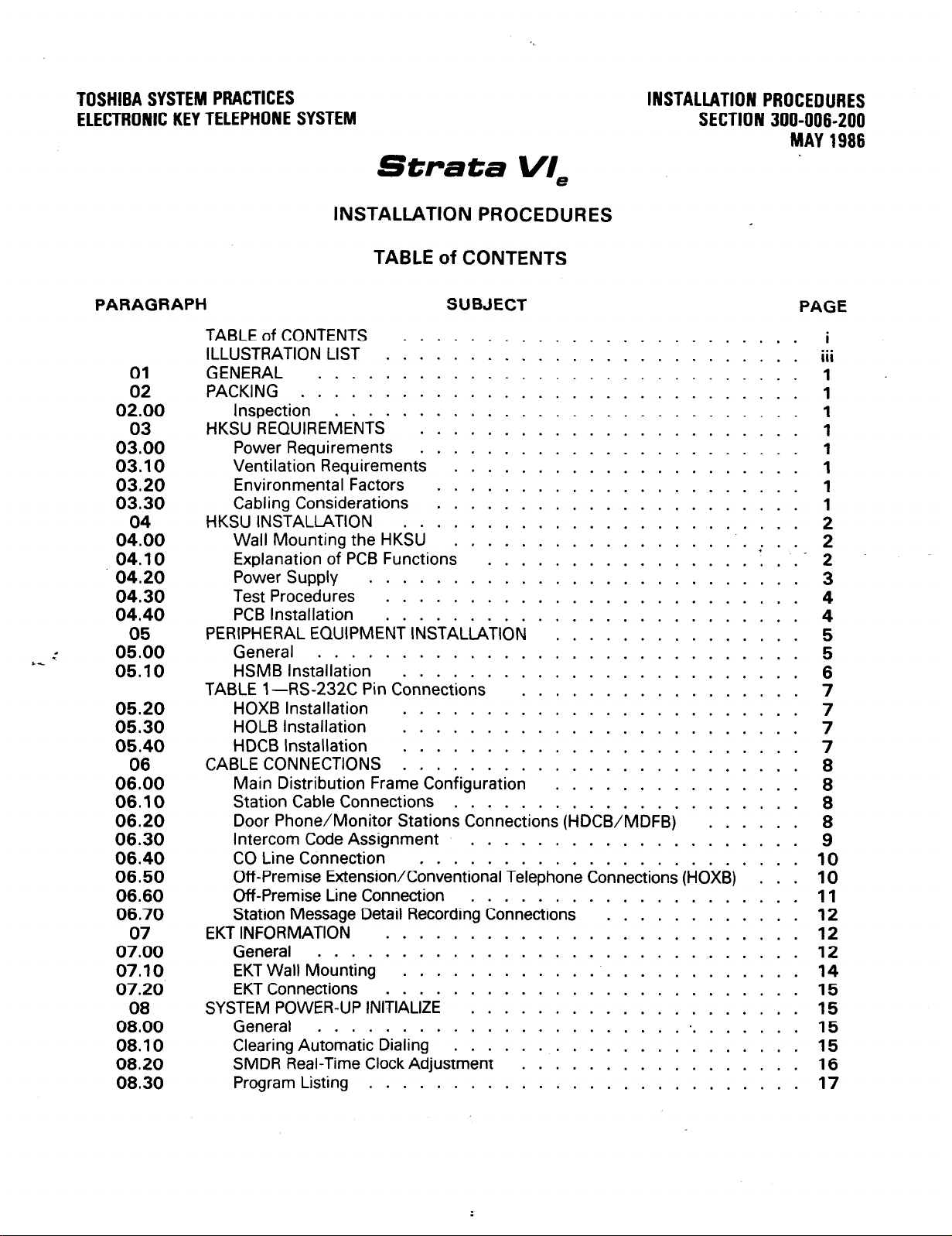
TABLE of CONTENTS
STRATA Vie
GENERAL DESCRIPTIGN
NOV_EMBER 1986
PARAGRAPH
01
02
03
04
05
06
07
SUBJECT
TABLE of CONTENTS
GENERAL
Summary Description
PHYSICAL DESCRIPTIONS
Key Service Unit
Peripheral Equipment
Electronic Key Telephones
ELECTRICALCHARACTERISTICS ’ : : : : : : : : : : : : : : : : : : : 3
General
FEATURESanbSEkVldES ’ 1 : : : : : : : : : : : : : : : : : 1 : : : 4
TABLE A-Summary of Electrical Characteristics
TABLE B-Standard Features
TABLE C-Optional Features
SYSTEM OPERATION
General
SYSTEM CONFIGURhTldN’ ’ : : : : : : : : : : : : : : : : : -: ; : :. 7
Key Service Unit
Option Modules
Station Equipment
Installation
Maintenance ...........................
FEATURES and OPERATION
General .............................
Standard Features
System .............................
Station ..............................
Optional Features
.....
............................
: : : : : : : : : : : : : : : : : : : : : : : : 1
.......................
......................
...............
.......
.............
........................
..........................
..........................
....................
.....................
........................
.........................
, ...............
....................
, .........
............
, .......
,
PAGE
... 9
10
10
10
10
10
10
12
13
i
1
1
1
2
2
3
4
5
5
6
6
7
8
FIGURE NO.
1
2
3
4
5
6
7
8
9
10
11
12
13
ILLUSTRATION LIST
TITLE
HKSU (Dimensions)
HKSU CABINET
HKSU (Internal View)
EXTERNAL MODULES
1 O-key ELECTRONIC
SINGLE-LINE EKT
lo-key BLF EKT
20-key EKT
20-key LCD EKT
SYSTEM DIAGRAM * : : : : : : : : : : : : : : : : : : : : : : : : :
FUNCTIONAL BLOCK DIAGRAM ...................
HKSU (with PCBs)
DOORPHONE
.............................
.........................
...........................
........................
........................
KEY TELEPHONE .................
..........................
...........................
..........................
...........................
PAGE
1
1
1
2
2
3
3
3
3
6
7
8
9
Page 3
STRATA We
GENERAL DESCRIPTION
NOVEMBER
1986
01 GENERAL
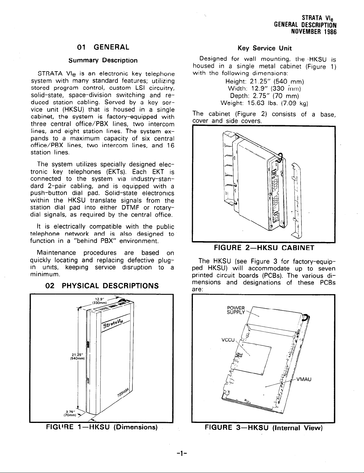
Summary Description
STRATA Vle is an electronic key telephone
system with many standard features; utilizing
stored program control, custom LSI circuitry,
solid-state, space-division switching and reduced station cabling. Served by a key service unit (HKSU) that is housed in a single
cabinet, the system is factory-equipped with
three central office/PBX lines, two intercom
lines, and eight station lines. The system ex-
pands to a maximum capacity of six central
office/PBX lines, two intercom lines, and 16
station lines.
The system utilizes specially designed electronic key telephones (EKTs). Each EKT is
connected to the system via industry-standard 2-pair cabling, and is equipped with a
push-button dial pad. Solid-state electronics
within the HKSU translate signals from the
station dial pad into either DTMF or rotarydial signals, as required by the central office.
Key Service Unit
Designed for wall mounting, the .HKSU
housed in a single metal cabinet (Figure 1)
with the following dimensions:
Height: 21.25” (540 mm)
Width: 12.9” (330 mm)
Depth: 2.75” (70 mm)
Weight: 15.63 Ibs. (7.09 kg)
The cabinet (Figure 2) consists of a base,
cover and side covers.
is
It is electrically compatible with the public
telephone network and is also designed to
function in a “behind PBX” environment.
Maintenance procedures are based on
quickly locating and replacing defective plugin units,
minimum.
keeping service
disruption to a
02 PHYSICAL DESCRIPTIONS
FIGURE 2-HKSU CA~INEI
The HKSU (see Figure 3 for factory-equipped HKSU) will accommodate up to seven
printed circuit boards (PCBs). The various dimensions and designations of these PCBs
are:
FIGtIRE 1 -HKSU (Dimensions)
FIGURE 3-HKSU (Internal View)
-l-
Page 4
STRATA Vie
GENERAL DESCRIPTION
NOVEMBER
VMAU: 9.75 x 15.37”
(248 x 390 mm)
VCOU: 5.75 x 10.60”
(146 x 269 mm)
VCCU: 6.00 x 6.50”
(152 x 165 mm)
SSTU: 4.13 x 4.60”
(105 x 117 mm)
SEFU: 4.25 x 3.00”
(108 x 76 mm)
SMOU: 2.25 x 1.13”
(57 x 29 mm)
The VMAU PC6 is secured directly to the base
of the cabinet; the remaining PCBs attach to
the VMAU.
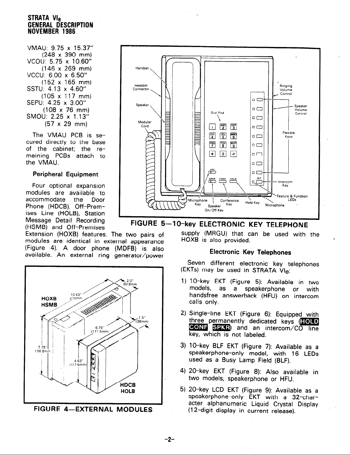
Peripheral Equipment
Four optional expansion
modules are available to
accommodate
Phone (HDCB), Off-Premises Line (HOLB), Station
Message Detail Recording
(HSMB) and Off-Premises
Extension (HOXB) features. The two pairs of
modules are identical in external appearance
(Figure 4). A door phone (MDFB) is also
available. An external ring generator/power
1986
the Door
Handset
\
Headset
COflneCtOr
\
FIGURE 5-lo-key ELECTRONIC KEY TELEPHONE
Rlnglng
Volume
~ Control
.oi
00
00
00
00
00
00
00
DO--
INT
- \ q
Microphone
Key
(
Speaker
On/Off Key
Conference
Key
\
Hold Key
supply (MRGU) that can be used with the
HOXB is also provided.
Electronic Key Telephones
Seven different electronic key telephones
(EKTs) may be used in STRATA Vle:
3 Speaker
- Intercom
Kev
‘Feature & Function
\
MIcrophone
r^
Volume
COlWOl
.
FIGURE 4-EXTERNAL
MODULES
1) lo-key EKT (Figure 5): Available in two
models, as a
speakerphone or
handsfree answerback (HFU) on intercom
calls only.
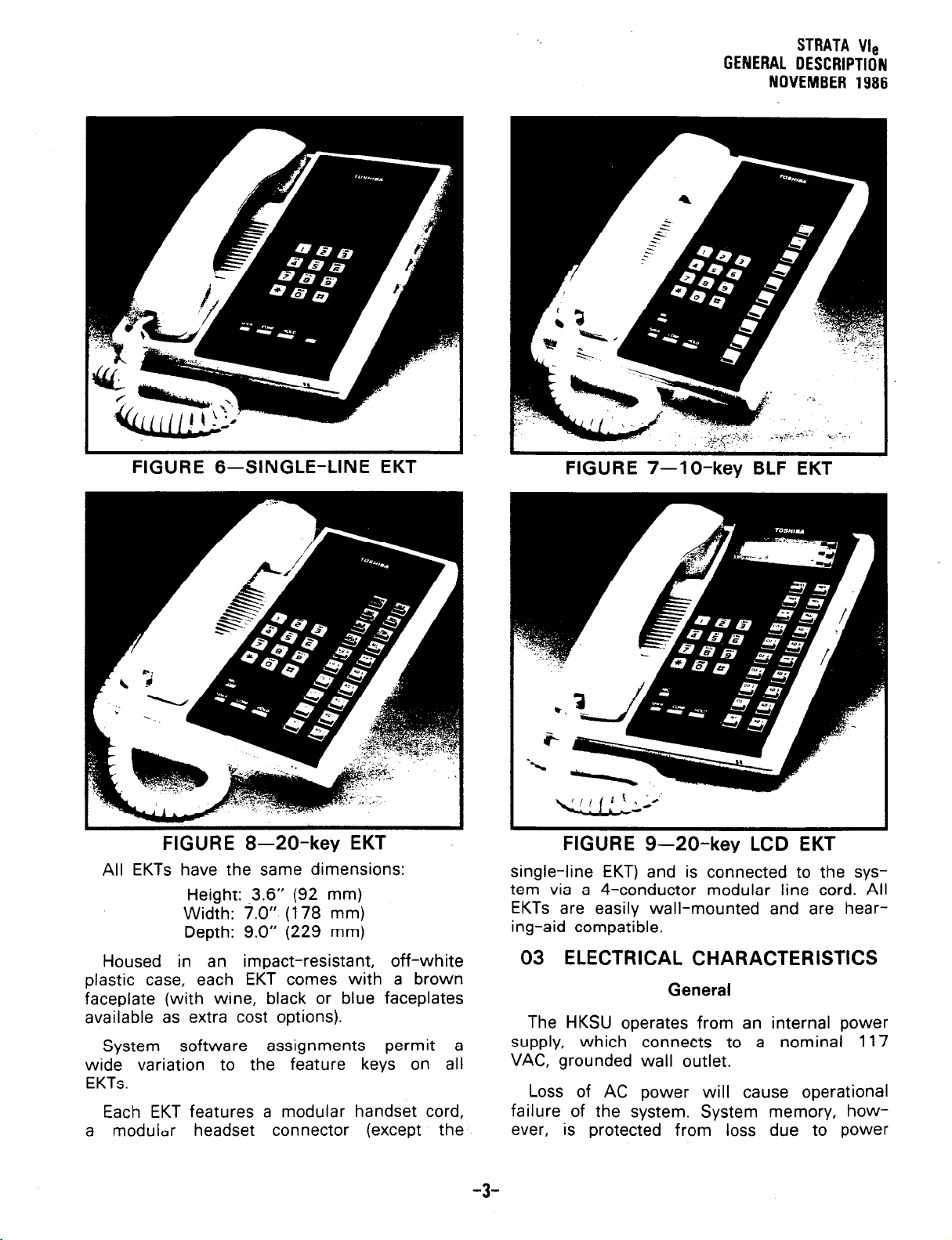
2) Single-line EKT (Figure 6): Equipped with
three permanently dedicated keys (m
=QzzI
and an intercom/CO line
key, which is not labeled.
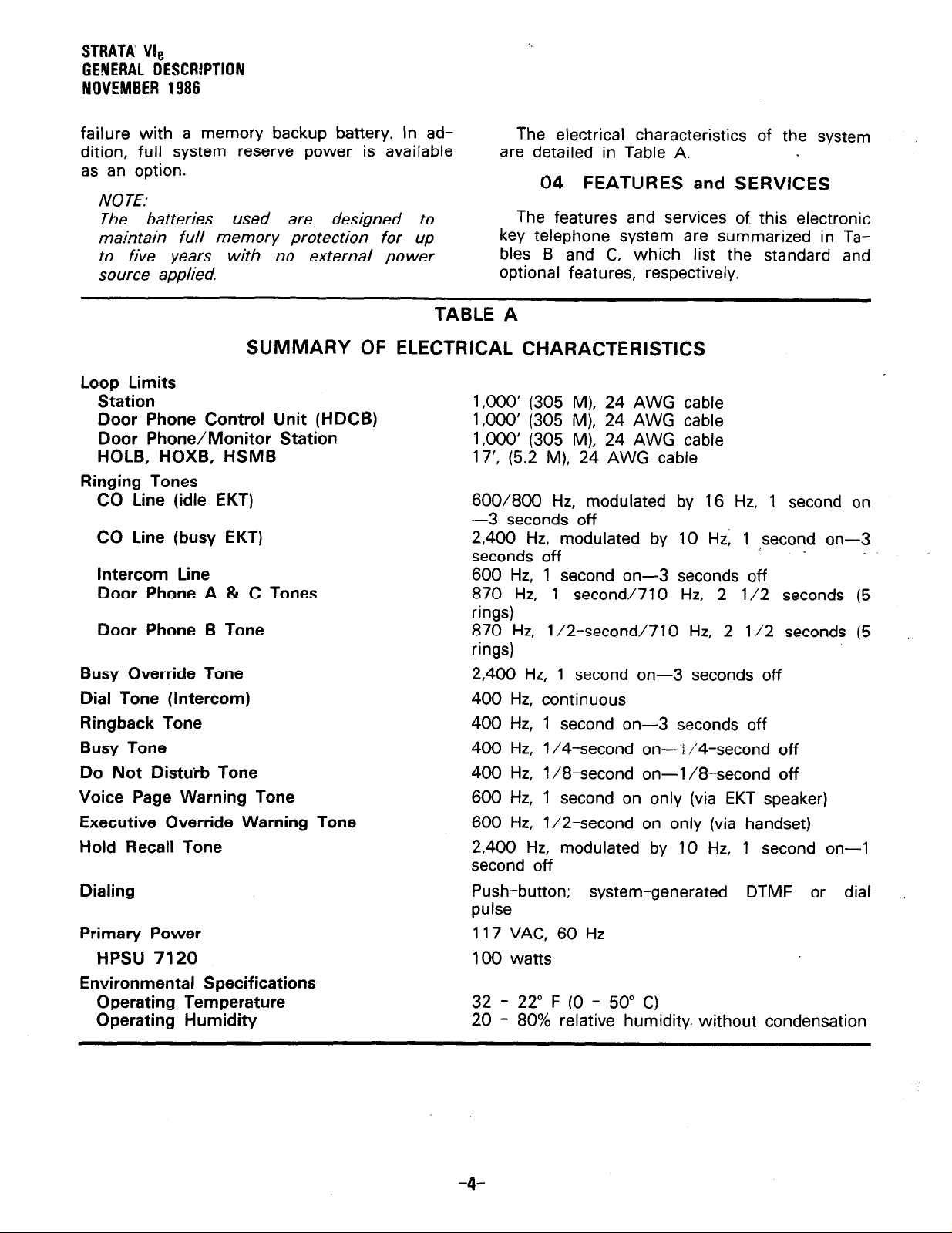
3) lo-key BLF EKT (Figure 7): Available as a
speakerphone-only model, with 16 LEDs
used as a Busy Lamp Field (BLF).
4) 20-key EKT (Figure 8): Also available in
two models, speakerphone or HFU.
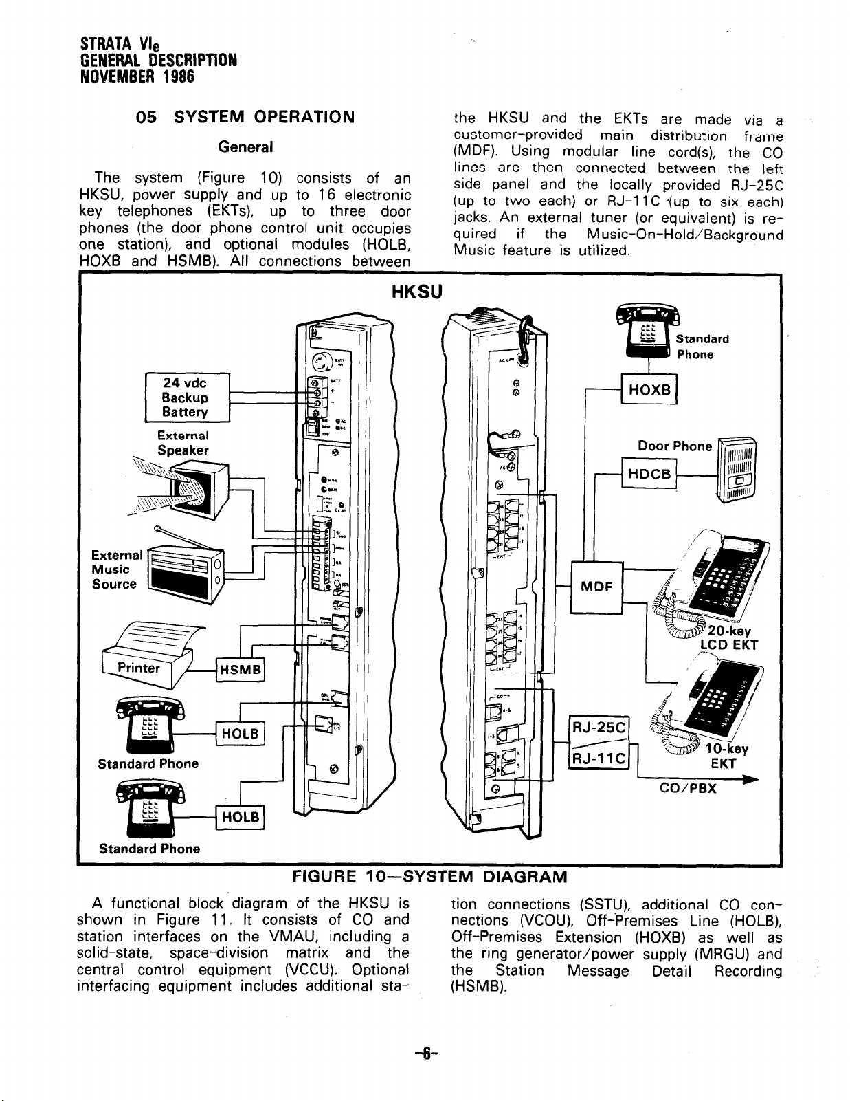
5) 20-key LCD EKT (Figure 9): Available as a
speakerphone-only EKT with a 32-character alphanumeric Liquid Crystal Display
(12-digit display in current release).
-2-
with
Page 5
STRATA We
GENERAL DESCRIPTION
NOVEMBER
1986
FIGURE 6-SINGLE-LINE EKT
FIGURE 8-20-key EKT
All EKTs have the same dimensions:
Height: .3.6” (92 mm)
Width: 7.0” (178 mm)
Depth: 9.0” (229 mm)
Housed in an impact-resistant, off-white
plastic case, each EKT comes with a brown
faceplate (with wine, black or blue faceplates
available as extra cost options).
System
wide variation to the feature keys on all
EKTs.
Each EKT features a modular handset cord,
a modulur headset connector (except the
software assignments permit a
FIGURE 7-lo-key BLF EKT
FIGURE 9-20-key LCD EKT
single-line EKT) and is connected to the system via a 4-conductor modular line cord. All
EKTs are easily wall-mounted and are hearing-aid compatible.
03 ELECTRICAL CHARACTERISTICS
General
The HKSU operates from an internal power
supply, which connects to a nominal 117
VAC, grounded wall outlet.
Loss of AC power will cause operational
failure of the system. System memory, however,
is protected from loss due to power
-3-
Page 6
STRATA Vls
GENERAL DESCRlPTlON
NOVEMBER 1986
failure with a memory backup battery. In addition, full system reserve power is available
as an option.
NOTE.
The batteries used are designed to
maintain full memory protection for up
to five years with no external power
source applied.
TABLE A
SUMMARY OF ELECTRICAL CHARACTERISTICS
Loop Limits
Station
Door Phone Control Unit (HDCB)
Door Phone/Monitor Station
HOLB, HOXB, HSMB
Ringing Tones
CO Line (idle EKT)
CO Line (busy EKT)
Intercom Line
Door Phone A & C Tones
Door Phone B Tone
Busy
Dial Tone (Intercom)
Ringback Tone
Busy
Do Not Distuib Tone
Voice Page Warning Tone
Executive Override Warning Tone
Hold Recall Tone
Dialing
Primary Power
Environmental Specifications
Override Tone
Tone
HPSU 7120
Operating Temperature
Operating Humidity
The electrical characteristics of the system
are detailed in Table A.
04 FEATURES
The features and services of this electronic
key telephone system are summarized in Tables B and C, which list the standard and
optional features, respectively.
1,000’ (305 M).
1,000’ (305 M)] 24
1,000’ (305 M), 24 AWG cable
17’, (5.2 M), 24 AWG cable
600/800 Hz,
-3 seconds off
2,400 Hz, modulated by 10 Hz; 1 second on-3
seconds off
600 Hz, 1 second on-3 seconds off
870 Hz, 1 second1710 Hz,
rings)
870 Hz, l/2-second/710 Hz, 2 l/2 seconds (5
rings)
2,400 Hz, 1 second on-3 seconds off
400
Hz, continuous
400 Hz, 1
400
Hz, l/4-second on-‘! /4-second off
400 Hz,
600
600
2,400
second off
Push-button; system-generated DTMF or dial
pulse
117 VAC, 60 Hz
100 watts
32 - 22” F (0 - 50” C)
20 - 80% relative humidity. without condensation
l/8-second on-l/8-second off
Hz, 1 second on only (via EKT speaker)
Hz, l/2-second on only (via handset)
Hz, modulated by 10 Hz, 1 second on-l
24 AWG cable
AWG cable
modulated by 16 Hz, 1 second on
second on-3 seconds off
and SERVICES
4
2 l/2 seconds (5
-4-
Page 7
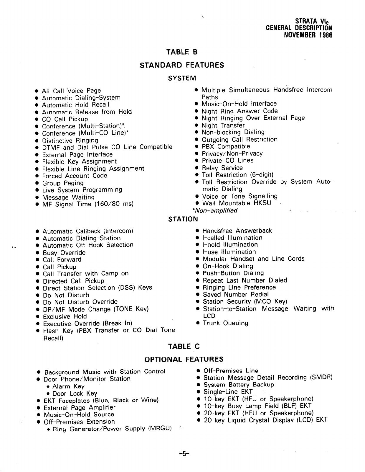
TABLE B
STANDARD FEATURES
SYSTEM
STRATA We
GENERAL DESCRIPTION
NO\IEMBER 1986
c-
l
All Call Voice Page
l
Automatic Dialing-System Paths
l
Automatic Hold Recall
l
Automatic Release from Hold
l
CO Call Pickup
l
Conference (Multi-Station)“.
l
Conference (Multi-CO Line)*
l
Distinctive Ringing
l
DTMF and Dial Pulse CO Line Compatible
o External Page Interface
l
Flexible Key Assignment
0 Flexible Line Ringing Assignment
l
Forced Account Code
l
Group Paging
* Live System Programming
l
Message Waiting
l
MF Signal Time (160/80 ms)
0 Multiple Simultaneous Handsfree Intercom
l
Music-On-Hold Interface
l
Night Ring Answer Code
l
Night Ringing Over External Page
l
Night Transfer
l
Non-blocking Dialing
l
Outgoing Call Restriction
0 PBX Compatible
l
Privacy/Non-Privacy
l
Private CO Lines
0 Relay Service
l
Toll Restriction (6-digit)
l
Toll Restriction Override by System Auto-
matic Dialing
l
Voice or Tone Signalling
l
Wall Mountable HKSU
*Non-amplified
STATION
0
Automatic Callback (Intercom)
0 Automatic Dialing-Station
l
Automatic Off-Hook Selection 0 l-hold Illumination
l
Busy Override
l
Call Forward
l
Call Pickup
l
Call Transfer with Camp-on
l
Directed Call Pickup
l
Direct Station Selection (DSS) Keys
0 Do Not Disturb
0 Do Not Disturb Override
l
DP/MF Mode Change (TONE Key)
l
Exclusive Hold
l
Executive Override (Break-In)
l
Flash Key (PBX Transfer or CO Dial Tone
l
Handsfree Answerback
l
l-called Illumination
0 l-use Illumination
l
Modular Handset and Line Cords
l
On-Hook Dialing
0 Push-Button Dialing
l
Repeat Last Number Dialed
l
Ringing Line Preference
l
Saved Number Redial
l
Station Security (MC0 Key)
l
Station-to-Station Message Waiting with
LCD
l
Trunk Queuing
Recall)
TABLE C
1
0
Background Music with Station Control
0 Door Phone/Monitor Station
l
Alarm Key
l
Door Lock Key
l
EKT Faceplates (Blue, Black or Wine)
l
External Page Amplifier
0 Music-On-Hold Source
l
Off-Premises Extension
l
Ring Generator/Power Supply (MRGU)
OPTIONAL FEATURES
0 Off-Premises Line
l
Station Message Detail Recording (SMDR)
l
System Battery Backup
l
Single-Line EKT
l
lo-key EKT (HFU or Speakerphone)
0 lo-key Busy Lamp Field (BLF) EKT
l
20-key EKT (HFU or Speakerphone)
l
20-key Liquid Crystal Display (LCD) EKT
-5-
.
Page 8
STRATA We
GENERAL
DESCRIPTION
NOVEMBER 1986
05 SYSTEM OPERATION
General
The system (Figure 10)
HKSU, power supply and up
key telephones (EKTs), up
phones (the door phone control unit occupies
one station), and optional modules (HOLB,
HC)XB and HSMB). All
._.. -
-..- ._... -,_
consrsts 01 an
to 16 electronic
to three door
connections
-- . ..-_-. -.--
r
between
--_____..
HK
the HKSU and the EKTs are made via a
customer-provided main distribution frame
(MDF). Using modular line cord(s), the CO
lines are then connected between the left
side panel and the locally provided
(up to two each) or RJ-11C (up to six each)
jacks. An external tuner (or equivalent) is re-
quired if the
Music feature is utilized.
Music-On-Hold/Background
:su
tandard
hone
/lHOXBl
RJ-25C
t-Printer
Standard Phone
Standard Phone
] HHSl
FIGURE lo--SYSTEM DIAGRAM
A functional block-diagram of the HKSU is
shown in Figure
station interfaces on the VMAU, including a
solid-state,
central control equipment (VCCU). Optional
interfacing equipment includes additional sta-
space-division
It consists of CO and
11.
matrix and the
RJ-25C
RJ-11C
i--h
tion connections (SSTU), additional CO connections (VCOU), Off-Premises Line (HOLB),
Off-Premises Extension (HOXB) as well as
the ring generator/power supply (MRGU) and
the
(HSMB).
-6-
Station Message
1
CO/PBX
Detail
EKT
*
Recording
Page 9
VMAU
SSTU #2 #22 - 25
STRATA Vie
GENEaAL DESCRIPTION
NOVEMBER
’ HOLB 1
__-
-
1986
Door Phone/
Monitor Station
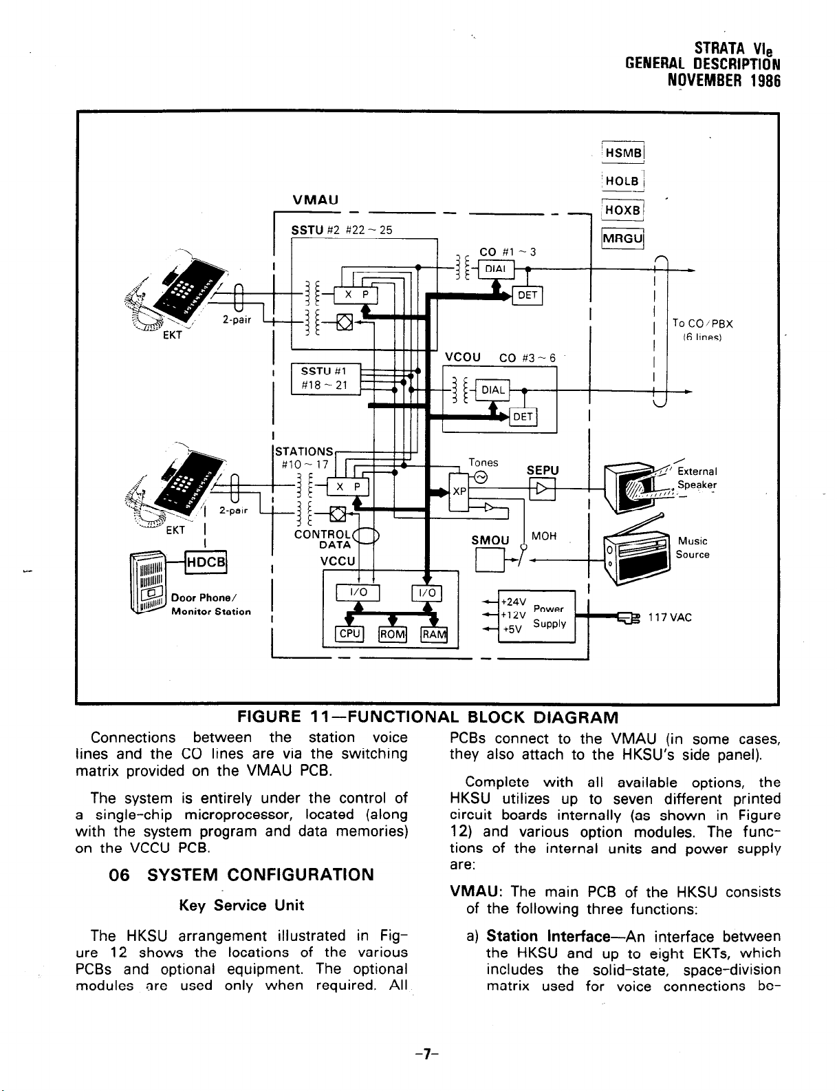
FIGURE 11 -FUNCTIONAL BLOCK DIAGRAM
Connections between the station voice
lines and the CO lines are via the switching
matrix provided on the VMAU PCB
The system is entirely under the control of
a single-chip microprocessor, located (along
with the system program and data memories)
on the VCCU PCB.
06 SYSTEM CONFIGURATION
Key
Service
The HKSU arrangement illustrated in Figure 12 shows the
PCBs and optional
modules are used
locations of the various
equipment. The optional
only when required. All
Unit
PCBs connect to the VMAU (in some cases,
they also attach to the HKSU’s side panel).
Complete with all available options, the
HKSU utilizes up to seven different printed
circuit boards internally (as shown in Figure
12) and various option modules. The functions of the internal units and power supply
are:
VMAU: The main PCB of the HKSU consists
of the following three functions:
a)
Station Interface-An
interface between
the HKSU and up to eight EKTs, which
includes the solid-state, space-division
matrix used for voice connections be-
-7-
Page 10
STRATA Vls
GENERAL DESCRIPTION
NOVEMBER d 986
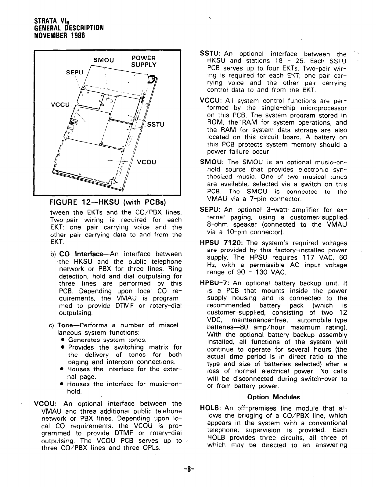
FIGURE 12-HKSU (with PCBs)
tween the EKTs and the CO/PBX lines.
Two-pair wiring
EKT: one pair carrying voice and the
other pair carrying data to and from the
EKT.
b) CO
c) Tone-Performs a number of miscel-
VCOU: An optional interface between the
VMAU and three additional public telehone
network or PBX lines. Depending upon local CO requirements, the VCOU is programmed to provide DTMF or rotary-dial
outpulsirg. The VCOU PCB serves up to
three CO/PBX lines and three OPLs.
Interface-An
the HKSU and the public telephone
network or PBX for three lines. Ring
detection, hold and dial outpulsing for
three lines are performed by this
PCB. Depending upon local CO requirements, the VMAU is programmed to provide DTMF or rotary-dial
outpulsing.
laneous system functions:
0
Generates system tones.
9
Provides the switching matrix for
the delivery
paging and intercom connections.
0
Houses the interface for the exter-
nal page.
0
Houses the interface for music-onhold.
is required for each
interface between
of tones for both
SSTU:
VCCU: All system control functions are per-
SMOU:
SEPU: An optional 3-watt amplifier for ex-
HPSU 7120:
HPBU-7:
An optional
HKSU and stations 18 - 25. Each SSTU
PCB serves up to four EKTs. Two-pair wiring is required for each EKT; one pair carrying voice and the other pair carrying
control data to and from the EKT.
formed by the single-chip microprocessor
on this PCB. The system program stored in
ROM, the--RAM for system operations, and
the RAM for system data storage are also
located on this circuit board. A battery on
this PCB protects system memory should a
power failure occur.
The SMOU is an optional music-on-
hold source that provides electronic syn-
thesized music. One of two musical tunes
are available, selected via a switch on this
PCB. The SMOU is connected to the
VMAU via a 7-pin connector.
ternal paging, using a customer--supplied
8-ohm speaker (connected to the VMAU
via a IO-pin connector).
The system’s required voltages
are provided by this factory-installed power
supply. The HPSU requires 117 VAC, 60
Hz, with a permissible AC input voltage
range of 90 - 130 VAC.
An optional battery backup unit. It
is a PCB that mounts inside the power
supply housing and is connected to the
recommended battery pack (which is
customer-supplied,
VDC, maintenance-free, automobile-type
batteries-80 amp/hour maximum rating).
With the optional battery backup assembly
installed, all functions of the system will
continue to operate for several hours (the
actual time period is in direct ratio to the
type and size of batteries selected) after a
loss of normal electrical power. No calls
will be disconnected during switch-over to
or from battery power.
interface between the ...
consisting of two 12
Option Modules
HOLB:
An off-premises line module that allows the bridging of a CO/PBX line, which
appears in the system with a conventional
telephone;
HOLB provides three circuits, all three of
which may be directed to an answering
supervision is provided. Each
.
-8-
Page 11
STRATA Vie
GENERAL DESCRWTION
NQVEMBER 1986
machine (or similar device) attached to the
HUNT connector.
HOXB: An external module that serves as
an interface between the HKSU and conventional, single-line telephones or offpremises
HOXB PC8 serves two extensions; one
HOXB per system. An HOXB will operate
with either DTMF or rotary-dial telephones.
An auxiliary ring generator/power supply
(MRGU) is required for the HOXB.
HSMB: Serves as an interface between the
HKSU and a printer or storage device used
for the SMDR feature. The module is
equipped with an RS-232C interface and
connects to the left side panel via two
supplied 8-wire modular connectors (one
HSMB per system).
HDCB: An optional module connected to the
HKSU at EKT 13 or 14 that allows up to
three door phone/monitor stations (MDFBs)
to ring pre-selected EKTs. The HDCB has
three outputs (A, B, C), which are modular
connectors for the three MDFBs. (Outputs
B and C may be used for the Door Lock
and Alarm features, respectively.)
The principal components of the lo-key
electronic key telephone (Figure 5) are: handset, dial pad, handsfree answerback (HFU)
nicrophone,
speaker and m key, two volume controls,
an m key, and nine CO/PBX line or fea-
extension
Station Equipment
microphone control key (m;
(OPX) lines. Each
two paragraphs, and has 10 additional feature keys.
A 20-key Liquid Crystal Display (LCD) EKT
(Figure 9), incorporating the same features as
those listed above for the 2O-key, may be
located at any or all of the stations. The 32character alphanumeric Liquid Crystal Display
(12-digit display in current release) provides
station-to-station message waiting capabili-
ties. Other features include an accurate
clock/calendar in its idle state; and elapsed
time, dialed number, calling station and CO
line are displayed
acters only.
All EKTs are
mounting, feature
equipped with a
for headset connection (except the single-line
EKT), and are connected to the system via
2-pair modular line cords.
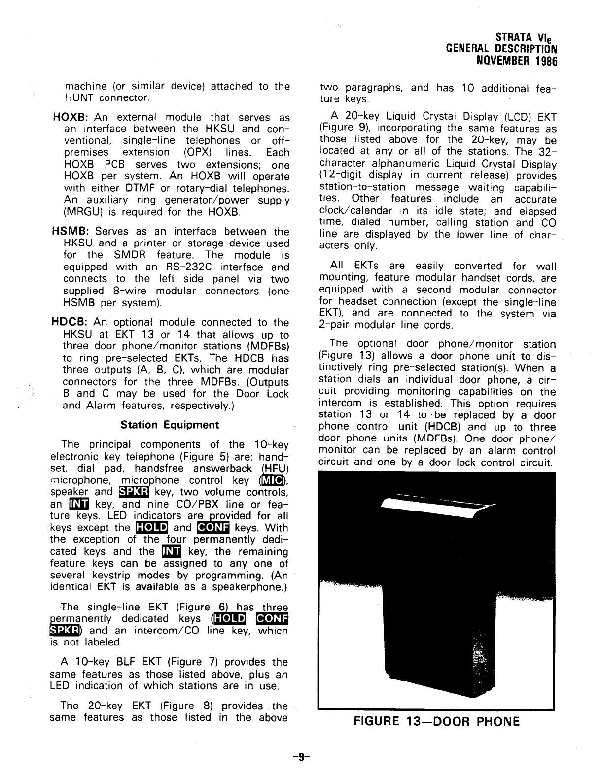
The optional door phone/monitor station
(Figure 13) allows a door phone unit to distinctively ring pre-selected station(s). When a
station dials an individual door phone, a circuit providing monitoring capabilities on the
intercom is established. This option requires
station 13 or 14 to be replaced by a door
phone control unit (HDCB) and up to three
door phone units (MDFBs). One door phone/
monitor can be replaced by an alarm control
circuit and one by a door lock control circuit.
by the lower line of char-
easily converted for wall
modular handset cords, are
second modular connector
the exception of the four permanently dedicated keys and the m key, the remaining
feature keys can be. assigned to any one of
several keystrip modes by programming. (An
identical EKT is available as a speakerphone.)
The single-line EKT (Figure
dedicated keys
and an intercom/CO line key, which
is not labeled.
A lo-key BLF EKT (Figure 7) provides the
same features as those listed above, plus an
LED indication of which stations are in use.
The 20-key EKT (Figure 8)
same features as those listed in the above
(
provides the
FIGURE 13-DOOR PHONE
-9-
Page 12
GENEBAL DESCRIPTION
NOVEMBER 1986
Installation
The HKSU is configured for wall mounting
only.
All external devices are connected to the
HKSU via connectors and terminals on the
side panels, as follows:
CO/PBX lines are connected‘to the HKSU
4
right side panel via two 3-pair or six
single-pair modular cords.
The station connection points are extended
b)
from the HKSU to the MDF using 2-pair
modular line cords. The individual EKTs
are connected to the MDF using 2-pair
station cables.
A screw-terminal barrier strip is mounted
d
on the left-hand side of the HKSU to pro-
vide attachment points for the music-onhold source input, relay service and external page output.
Two modular connectors are also provided
4
on the left side panel for two optional offpremises line modules (HOLBs).
The power supply is mounted inside the
HKSU (an optional battery backup PCB is
available for the power supply).
Maintenance
Automatic Dialing-System:
bers to be stored in the system’ memory.
After selecting an outgoing line, any sta-
tion user can cause one of the stored
numbers to be outpulsed 1 by dialing the
proper access code.
Automatic Hold Recall:
hold by any station will recall that station
after a programmable period of time. A
different time period can be selected for
each station.
Automatic Release from Hold:
automatically releases held CO lines if a
disconnect signal is received from the central off ice.
CO
Call Pickup:
CO call pickup from another station.
Conference (Multi-Station): Non-amplified
conferencing is permitted. to a maximum of
four stations and one CO
ing is not amplified.)
Conference (Multi-CO Line):
will conference two CO lines and up to
three stations. (Conferencing is not amplified.)
Distinctive Ringing: CO
are distinguished by different ringing tones.
Using a dial code, allows
Allows 40 num-
A CO line placed on
The system
line. (Conferenc-
The system
and intercom calls
.
Faults in the system are repaired by replacing any faulty component (PCB, subassembly, telephone, etc.) and returning it to
the manufacturer for repair.
07 FEATURES and OPERATION
General
This section contains brief descriptions of
the features listed earlier in Tables B and C
and some associated operating instructions.
Detailed operating instructions can be found
in the EKT
All Call Voice Page:
code permits a station user to page via all
idle EKT speakers simultaneously. The system can also be programmed to include
the Ext,rnal Page feature in an All Call
Page.
USER GUIDE.
Standard Features
System
Dialing a 2-digit access
DTMF and Dial Pulse CO Line Compatible:
The system will interface
DTMF or rotary-dial pulse CO lines on a
line-by-line basis as determined by system
programming.
External Page Interface:
nection point is provided for a customerprovided external amplifier/speaker. The
SEPU (see External Page Amplifier) can be
mounted in the HKSU when only a customer-provided external speaker is used;
the output impedance will be 8 ohms. This
page circuit can be accessed as part of
the All Call Voice Page feature.
Flexible Key Assignment:
to be programmed for optimum use of its
CO/PBX or feature keys.
Flexible Line Ringing Assignment:
grammable ring or no ring option is provided for each line selectively by each sta-
A 600-ohm con-
with either
Allows each EKT
A pro-
-lO-
Page 13
STRATA Vls
GENERAL DESCRIPTION
NOVEMBER 1986
tion. Each
a maximum of
Forced Account Code:
station(s) to dial an account code prior to
dialing a number. The account code is recorded with call details on the SMDR report.
Group Paging:
(81, 82, 83 or 84) permit voice paging to
one of four zones. Zone assignment is via
software and is totally flexible. Paging is
via the speakers of idle EKTs.
Live System Programming:
gramming is accomplished without service
interruption to other station users by plac-
ing the system in the special programming
mode and inputting data via station 17.
Station 17 is the only station that is
“down” during programming.
Message Waiting:
designated Message Center) can set a
Message Waiting LED at any station with
the Message Waiting LED of that station.
The called station cancels the LED by lift-
in the handset and depressing the
*
EKT). Also see Flash key.
MF Signal Time (160180 ms):
MF dial signal time is 80 milliseconds, but
it may be extended to 160 milliseconds, if
required by the CO or to activate remote
equipment.
Multiple Simultaneous Handsfree Intercom
Paths:
the system. Both intercom lines are able
to carry handsfree conversation simultane-
ously.
Music-On-Hold Interface:
included for a customer-provided music
source. CO lines placed on hold will be
connected to this source. In addition, this
music may also be broadcast from EKT
speakers and external page when the
background music programming options are
selected.
Night Ring Answer Code:
call may be answered from any station via
a dial code.
line may be programmed to ring
eight stations.
Requires selected
Special 2-digit access codes
Live system pro-
Any station (including the
key (not available on single-line
The standard
Two intercom paths are available in
An interface is
A night ringing
Night Ringing Over External Page:
programmable option, while the night
mode is active,
tone will be transmitted via the external
speaker whenever any line rings.
Night Transfer:
basis, the system can function with two or
three ringing patterns. If three patterns are
selected, they are designated DAY, DAY 2,
and NITE. If the two-pattern mode is selected, DAY and NITE designations are
used. In both cases, the ringing
selected with the
Non-blocking Dialing:
on intercom and all CO lines simultaneously.
Outgoing Call Restriction:
be selectively restricted from originating
calls on any or all CO lines. However, the
station may still receive calls on the restricted line(s).
PBX Compatible:
tures, such as Toll Restriction and Auto-
matic Dialing, are compatible with PBX op-
eration.
Privacy/Non-Privacy:
vents other stations from accessing the intercom or CO lines that are already in
use. A non-private system provides conferenting on the CO and intercom lines.
Private CO Lines:
grammed into the system so that selected
CO line(s) will appear only on selected
station(s).
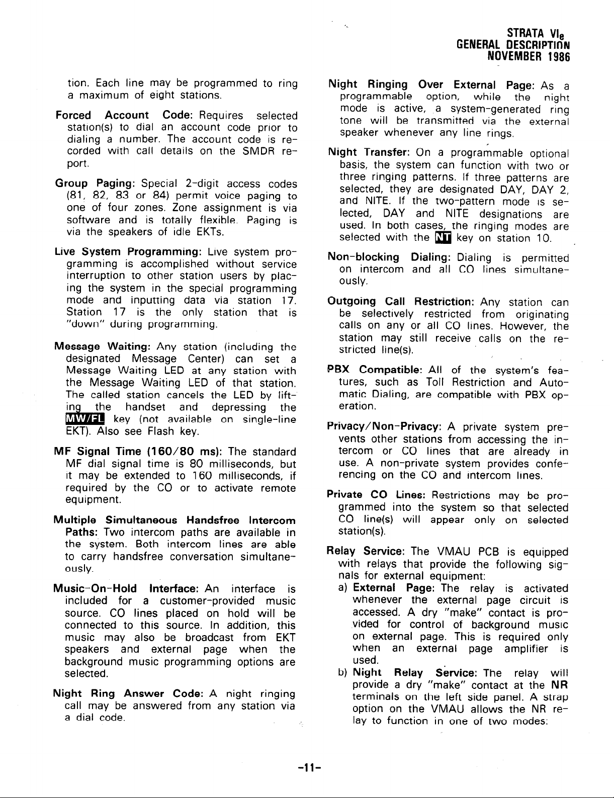
Relay Service:
with relays that provide the fotlowing signals for external equipment:
External Page:
4
whenever the external page circuit is
accessed. A dry “make” contact is provided for control of background music
on external page. This is required only
when an external page amplifier
used.
Night Relay S&vice:
t-4
provide a dry “make” contact at the
terminals on the left side panel. A strap
option on the VMAU allows the NR relay to function in one of two modes:
a system-generated ring
On a programmable optional
modes are
q
key on station 10.
Dialing is permitted
Any station can
All of the system’s fea-
A private system pre-
Restrictions may be pro-
The VMAU PCB is equipped
‘The relay is activated
The relay will
As a
_
is
NR
-ll-
Page 14
STRATA Vie
GENERAL DESCRIPTION
NOVEMBER
1986
1) Answering Machine Control:
strap remains intact, the relay is operated continuously when the system
is in night service. This mode is intended for indirect control of an answering machine.
2)
Night Bell Control:
cut, the relay pulses at a l-second
on/3-seconds off rate whenever the
system is in Night Transfer mode
and an incoming call is ringing the
system. This mode is intended to be
used for indirect control of an external night bell.
Toll Restriction (6-digit):
grammed on a station class of service basis. The system performs toll restriction by
analyzing the first 6 or 3 digits (area/
office code) dialed. Simple restriction by
rejecting the numbers 0 and
programmed on a per-station basis, if desired.
Toll Restriction Override by System Auto-
matic
feature that permits numbers stored by the
Automatic Dialing-System feature to be
called by toll-restricted stations.
Dialing:
A programmable system
If the strap is
Selectively pro-
1
can be
If the
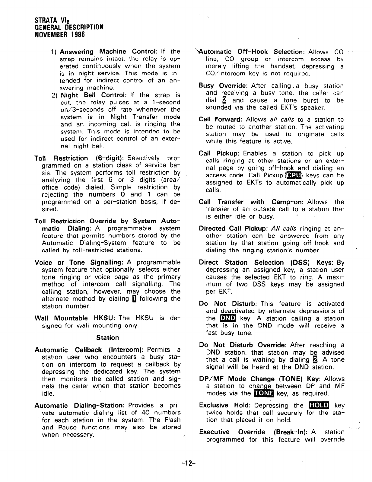
%utomatic Off-Hook Selection:
line, CO group or intercom access by
merely lifting the handset; depressing a
CO/intercom key is not required.
Busy Override:
and receiving a busy tone, the caller can
dial l and
sounded via the called EKT’s speaker.
Call Forward:
be routed to another station. The activating
station may be used to originate calls
while this feature is active.
Call Pickup:
calls ringing at other stations or an exter-
nal page by going off-hook and dialing an
access code. Call Pickup(m keys can be
assigned to EKTs to automatically pick up
calls.
Call Transfer with Camp-on:
transfer of an outside call to a station that
is either idle or busy.
Directed Call Pickup:
other station can be answered from any
station by that station going off-hook and
dialing the ringing station’s number.
After calling, a busy station
cause a tone burst to be
Allows all calls to a station to
Enables a station to pick up
All calls ringing at an-
Allows CO
Allows the
/ -
Voice or Tone Signalling:
system feature that optionally selects either
tone ringing or voice page as the primary
method of intercom call signalling. The
calling station,
alternate method by dialing 0 following the
station number.
Wall Mountable
signed for wall
Automatic Callback (Intercom):
station user who encounters a busy sta-
tion on intercom to request a callback by
depressing the dedicated key. The system
then monitors the called station and sig-
nals the caller when that station becomes
idle.
Automatic Dialing-Station:
vate automatic dialing list of 40 numbers
for each station in the system. The Flash
and Pause functions may also be stored
when necessary.
however, may choose the
HKSU:
mounting only.
Station
A programmable
The HKSU is de-
Permits a
Provides a pri-
Direct Station Selection
depressing an assigned key, a station user
causes the selected EKT to ring. A maxi-
mum of two DSS keys may be assigned
per EKT.
Do Not Disturb:
and deactivated by alternate depressions of
the m key. A station calling a station
that is in the DND mode will receive a
fast busy tone.
Do Not Disturb Override:
DND station, that station may be advised
that a call is waiting by dialing 1. A tone
signal will be heard at the DND station.
DP/MF
a station to than e between DP and MF
modes via the
Exclusive Hold: Depressing the m key
twice holds that call securely for the sta-
tion that placed it on hold.
Executive Override (Break-In): A station
programmed for this feature will override
Mode Change (TONE) Key:
This feature is activated
l
i&
(DSS) Keys: By
After reaching a
Allows
key, as required.
-12-
Page 15

STRATA We
GENERAL DESCRIPTION
NI)VEMBER
1986
the automatic privacy feature and enter
any existing conversation within the sys-
tem. A warning tone, however, is inserted
before the overriding station is actually
connected. After reaching a busy station,
dial a 1 to override.
Flash Key (PBX Transfer or CO Dial Tone
Recall):
Message
which, when operated while connected to
a CO/PBX line, causes a timed “flash” to
be transmitted to the CO or PBX. The timing of the flash can be programmed to
signal a PBX for feature operation or can
be long enough to cause a disconnect and
dial -tone recall on a CO line (not available
on single-line
Waiting.
Handsfree Answerback:
single-line EKT) are equipped for handsfree
answerback on voice-announced intercom
calls as a standard feature.
l-called Illumination:
pears on the intercom LED at the EKT
that is actually being called.
l-hold Illumination:
a distinctive LED flash to indicate a line
placed on hold at the EKT. Other stations
see a normal on-hold flash.
l-use Illumination:
shows the line presently in use at a given
EKT. Other stations see a steadily illumi-
nated LED for that line.
Modular Handset and Line Cords:
are equipped with modular handset and
line cords, and (except for the single-line
EKT) are also equipped with an additional
modular headset jack.
On-Hook Dialing:
dial your calls with the handset still onhook. Call progress can be heard via the
telephone speaker;. no need to pick up the
handset until your party answers.
Push-Button Dialing:
with push-button dial pads.
Repeat Last
numbet dialed by each station is always
EKTs can be equi
Waiting/Flash
EKT). Also see Message
All EKTs (except the
A distinctive flash ap-
The EKT user is shown
A distinctive flash rate
The system allows you to
All EKTs are equipped
Number Dialed:
ed with a
(b key
All EKTs
The
last
stored by the system and will .be dialed
automatically whenever the station user
accesses a CO line and depresses the B
or m key.
Ringing Line Preference:
station can be answered b
handset or depressing the
ringing line will be automatically selected.
Saved Number Redial:
that saves a dialed number for redial at a
later time. May be used at any time and
is exclusive of the Repeat Last Number.
Dialed feature.
Station Security (MC0 Key):
station to individually enable or disable the
Handsfree Answerback feature.
Station-to-Station Message Waiting with
LCD:
sent to another station, indicating that the
displayed station has called. See 20-key
Liquid Crystal Display EKT.
Trunk Queuing:
users to be “stacked” in a waiting queue
for a .busy outgoing trunk group by using
the Automatic Callback feature. The station
will then be signalled when a trunk in the
group becomes available. As a programmable option, the system may be equipped
with one trunk group (dial 9) or four trunk
groups (dial 91, 92, 93, 94).
Background Music with Station Control:
Music from the music-on-hold source can
(at the station user’s option) be heard via
the EKT speaker.
also be broadcast via the external page
interface if an external speaker is installed.
Door Phone/Monitor Station:
tional door phone unit(s) to distinctively
ring pre-selected EKTs. EKT dialing to an
individual door phone unit provides moni-
toring capabilities on the intercom.
An EKT’s station number may be
Provides a means for station
Optional Features
The same music may
l
Alarm Key:
set in the system by a customer-supplied alarm system. The alarm signal is
activated by a closure at the HDCB
door phone C output from a customersupplied alarm system. The alarm signal
Turns off the alarm signal
A line ringing a
lifting the
’ .
&I
A programmable key
key. The
Allows each
Allows op-
-13-
Page 16
STRATA
Vie
GENERAL DESCRIPTION
NOVEMBER 1986
will be heard from all idle EKTs until
the alarm key is depressed (station 10
only).
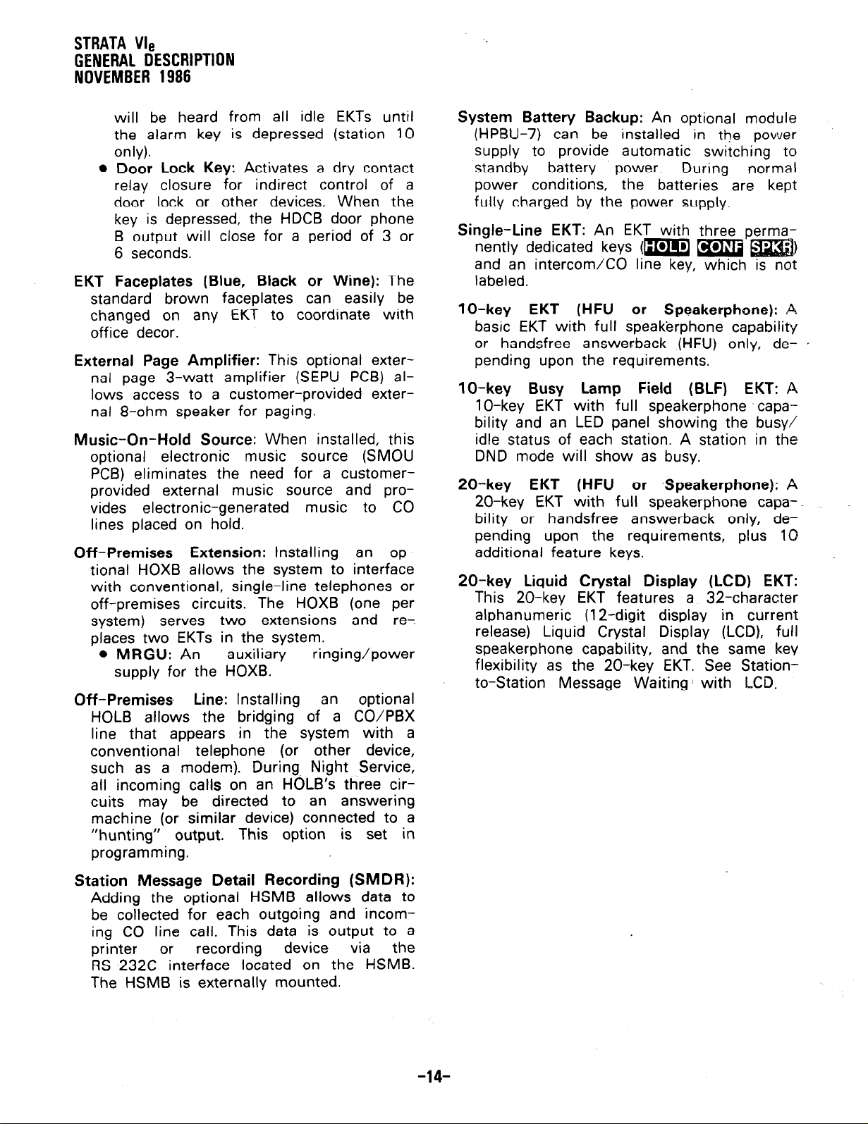
l
Door Lock
relay
closure for indirect control of a
Key:
Activates a dry contact
door lock or other devices. When the
key is depressed, the HDCB door phone
B output will close for a period of 3 or
6 seconds.
EKT Faceplates (Blue, Black or Wine):
standard brown faceplates can easily be
changed on any EKT to coordinate with
office decor.
External Page Amplifier:
This optional external page 3-watt amplifier (SEPU PCB) allows access to a customer-provided external 8-ohm speaker for paging.
Music-On-Hold Source:
optional electronic
When installed, this
music source (SMOU
PCB) eliminates the need for a customer-
provided external music source and provides electronic-generated music to CO
lines placed on hold.
Off-Premises Extension:
Installing an optional HOXB allows the system to interface
with conventional, single-line telephones or
off-premises circuits.
system) serves
The HOXB (one per
two extensions and re-
places two EKTs in the system.
l
MRGU:
An
auxiliary
ringing/power
supply for the HOXB.
Off-Premises Line:
Installing an optional
HOLB allows the bridging of a CO/PBX
line that appears in the system with a
conventional telephone (or other device,
such as a modem). During Night Service,
all incoming calls on an HOLB’s three circuits may be directed to an answering
machine (or similar device) connected to a
“hunting” output. This option is set in
programming.
The
System Battery Backup:
An optional module
(HPBU-7) can be installed in the power
supply to provide automatic switching to
standby battery power. During normal
power conditions, the batteries are kept
fully charged by the power supply.
Single-Line EKT:
An EKT with three
nently dedicated keys (m a
and an intercom/CO line key, which is not
labeled.
lo-key EKT (HFU or Speakerphone): A
basic EKT with full speakerphone capability
or handsfree answerback (HFU) only, depending upon the requirements.
1
O-key Busy Lamp Field (BLF) EKT:
A
1 O-key EKT with full speakerphone capa-
bility and an LED panel showing the busy/
idle status of each station. A station in the
DND mode will show as busy.
20-key EKT (HFU or -Speakerphone):
A
20-key EKT with full speakerphone capa-.
bility or handsfree answerback only, depending upon the requirements, plus 10
additional feature keys.
20-key Liquid Crystal Display (LCD) EKT:
This 20-key EKT features a 32-character
alphanumeric (12-digit display in current
release) Liquid Crystal Display (LCD), full
speakerphone capability, and the same key
flexibility as the 20-key EKT. See Stationto-Station Message Waiting: with LCD,
.
Station Message Detail Recording (SMDR):
Adding the optional HSMB allows data to
be collected for each outgoing and incoming CO line call. This data is output to a
printer or
recording
device
via the
RS-232C interface located on the HSMB.
The HSMB is externally mounted.
-14-
Page 17
TOSHIBA SYSTEM PRACTICES
ELECTRONIC KEY TELEPHONE SYSTEM
INSTALLATION PROCEDURES
SECTION 300-006-200
MAY 1986
Strata@ Vi/,
,-
INSTALLATION PROCEDURES
Page 18
TOSHIBA
SYSTEM PRACTICES
ELECTRONIC KEYTELEPHONE SYSTEM
INSTALLATION PROCEDURES
INSTALLATION PROCEDURES
SECTION 300-006-200
MAY 1986
Strata VI,
TABLE of CONTENTS
PARAGRAPH
01
02
02.00
03
03.00
03.10
03.20
03.30
04
04.00
04.10
04.20
04.30
04.40
05
05.00
05.10
05.20
05.30
05.40
06
06.00
06.10
06.20
06.30
06.40
06.50
06.60
06.70
079’00
07.10
07.20
08
08.00
08.10
08.20
08.30
SUBJECT
TABLE of CONTENTS
ILLUSTRATION LIST . : : : : : : : : : : : : : : : : : : : : : : : :
GENERAL
PACKING . : : : : : : : : : : : : : : : : : : : : : : : : : : : : :
Inspection
HKSU REQUIREMENTS’ ’ : : : : : : : : : : : : : : : : : : : : : : :
Power Requirements
Ventilation Requirements
Environmental Factors
Cabling Considerations
. . . . . . . . . . . . . . . . . . . . . . .
. . . . . . . . . . . . . . . . . . . . .
. . . . . . . . , . . . . . . . . . . . . .
. . . . . . . . . . . . . . . . . . . . . .
HKSU INSTALLATION
Wall Mounting the HKSU
Explanation of PC6 Functions
Power Supply
Test Procedures
. . . . . . . . . . . . . . . . . . . . . . . . . .
. . . . . . . . . . . . . . . . . . . . . . . . .
’ : : : : : : : : : : : : : : : : : : : : :
. . . . . . . . . . . . . . . . : . .
PCB Installation
PERlPHERALEQUlPMENiINS’TALtiTIQN
General
HSMB Installation
. . . . . . . . . . .
. . . . . .
TABLE 1 -RS-232C Pin Connections
HOXB Installation
HOLB Installation
HDCB Installation
CABLE CONNECTIONS
. . . . . .
. . . . . .
. . . . . .
. , . . . .
Main Distribution Frame Configuration
’ : : : : : : : : : : : : : : :
..................
..................
.................
..................
..................
..................
..................
. . . . . . . . . . . . . . .
Station Cable Connections
Door Phone/Monitor Stations Connections (H&B/‘MDFB)
Intercom Code Assignment
. . . . . . . . . . . . . . . . . . . .
’ : : : : : :
CO Line Connection
Off-Premise Extension/Conventional Telephone Connections (HOXB)
Off-Premise Line Connection
Station Message Detail Recording Connections
. . . . . . . . . . . . . . . . . . . .
. . . . . . . . . . . .
’ : : :
EKT INFORMATION
General
EKT Wall Mounting
. . . . : : : : : : : : : : : : : : : : : : : : : : : : :
. . . . . . . . . . . . . . . . . . . . . . . .
EKT Connections
SYSTEM POWER-UP INlilALiZE
General
. . . . . . . . . . . . . . . . . . . . . . . . . . . . . .
Clearing Automatic Dialing
SMDR Real-Time Clock Adjustment
Program Listing
. . . . . . . . . . . . . . . . . . . . . . . . . .
’ : : : : : : : : : : : : : : : : : : : :
. . . . . . . . . . . . . . . . . . . . .
. . . . . . . . . . . . . . . . .
PAGE
. . .
III
1
1
1
1
1
1
1
1
2
2
2
3
4
4
5
5
6
7
7
7
7
8
8
8
8
9
10
10
11
12
12
12
14
15
15
15
15
16
17
i
Page 19
INSTAUATION PROCEDURES
SECTION 300-006-200
MAY 1986
ELECTRONIC KEY TELEPHONE SYSTEM
Strata
VI,
INSTALLATION PROCEDURES
TABLE of CONTENTS (continued)
TOSHIBA SYSTEM PRACTICES
PARAGRAPH
09
09.00
09.10
09.20
09.30
09.40
10
10.00
10.10
10.20
10.30
10.40
10.50
10.60
10.70
10.80
10.90
SUBJECT
SYSTEM TEST PROCEDURES
EKT Functional Check
Off-Premise Extension/Conventional Telephone Functional Check
OPL Circuit Functional Check 19
SMDR Functional Check
Feature Check
MISCELLANEOUS
Wiring Connections
MOH/BGM Source
Music-On-Hold Volume Control
External Paging Connections
Direct External Speaker Connection
External Amplifier Connection
Talkback Amplifier
Background Music
Volume Setting Sequence
Night Relay Service
E&i&&f C&JN~C~I~NS’
........................
........................
........................
........................
.....................
.......................
...
. . : : : : : : : : : : : : : : : : : : :
1 1 1 1 1 1 1 1 1 1 1 1 1
.......................
..................
...................
................
...................
.....................
PAGE
17
17
18
20
20
20
20
20
20
20
21
21
;
21
22
22
23
A
-ii-
Page 20
TOSHIBA SYSTEM PRACTICES
ELECTRONIC KEY TELEPHONE SYSTEM
INSTALLATION PROCEDURES
Strata VI,
ILLUSTRATION LIST
INSTALlATlON PROCEDURES
SECTION 300-006-200
MAY
1986
NUMBER
1
2
3
4
5
6
7
8
9
10
11
12
13
14
15
16
17
18
::
21
22
23
24
25
26
27
28
29
30
31
32
33
ZZ’
36
37
38
39
TITLE
VCCU
Battery
HKSUSideCovers
HKSUWallMounting
HKSU(withPCBs)
HPBU Installation
HKSUCoverRemoval
SSTU Location(s)
SEPULocation .........................................................
VCOULocation
External Module Wall Mounting
HSMB Connection Straps
HOXB Connection Straps
HDCB Connection Straps
SystemDiagram
EKTWiring ...........................................................
RJ-11 C/RJ-25C Color Code
HDCB/MDFB Connection
HKSU Right Side Panel
HOXBWiring ..........................................................
HOLBWiring ..........................................................
HSMB/Printer Cabling
lo-keyEKT ...........................................................
lo-keyBLFEKT
20-key EKT ...........................................................
20-key LCD EKT
Removing EKT Base
EKTWireAccess
EKTWireRouting
HandsetHanger
VCCU Battery Strap
Initialize Switch
HSMBSwitchesandLEDs
SMDR Printout Example (Outgoing Call Record)
SMDR Printout Example (Incoming Call Record)
TerminalStrip ..........................................................
ImpedanceSwitch
External Amplifier Hook-up
Volume Setting Controls
Relay
Contacts
Strap
.....................................................
.....................................................
...................................................
......................................................
......................................................
...................................................
.......................................................
........................................................
...........................................
................................................
................................................
................................................
.......................................................
...............................................
...........................................
..................................................
..................................................
........................................................
.......................................................
....................................................
.......................................................
......................................................
.......................................................
.....................................................
........................................................
...............................................
......................................................
...............................................
.................................................
........................................................
..............................
..............................
PAGE
:
2
2
3
4
5
5
5
6
7
7
8
9
8
10
....
.
10
10
11
11
12
12
13
13
13
14
14
14
15
15
15
16
20
20
21
21
22
22
23
-Ill-
. . .
Page 21
01 GENERAL
INSTALLATION PROCEDURES
SECTION 300-006-200
MAY 1986
01 .Ol
procedures necessary to ensure proper operation of the
This section describes the installation
Strata V/e
system.
02 PACKING
02.00
02.01 When a
received, examine all packages and carefully
note any visible damage. If any damage is
found, bring it to the attention of the delivery
carrier and make the proper claims.
02.02
contents of the
against the purchase order and packing slip. If
it is determined that any cartons are missing,
contact your delivery carrier immediately. If it
is determined that any equipment within a car-
ton is missing, contact your Toshiba supplier
immediately.
02.03 After unpacking (prior to beginning
the installation), inspect all equipment for
damage. If any damage is detected, contact
your delivery carrier immediately. If possible,
retain all the original packing material.
When handling (installing, removing,
examining, etc.) a printed circuit board,
do not touch the back (soldered) side or
the pin connector. Always hold a PCB
by its edge.
02.04
ensure the following:
Inspection
Strata V/e
Check the number of cartons and the
Strata We
CAUTION!
When packing or storing a VCCU,
system is
shipment
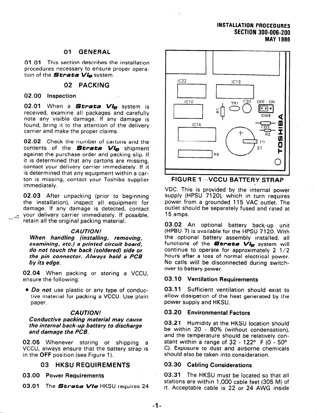
FIGURE 1
VDC. This is provided by the internal power
supply (HPSU 7120), which in turn requires
power from a grounded 115 VAC outlet. The
outlet should be separately fused and rated at
15 amps.
03.02 An optional battery back-up unit
(HPBU-7) is available for the HPSU 7120. With
the optional battery assembly installed, all
functions of the
continue to operate for approximately 2 l/2
hours after a loss of normal electrical power.
No calls will be disconnected during switch-
over to battery power.
03.10 Ventilation Requirements
-VCCU BATTERY STRAP
Strata V/e
e
system will
l
Do not
tive material for packing a VCCU. Use plain
paper.
Conductive packing material may cause
the internal back-up battery to discharge
and damage the PCB.
02.05
VCCU, always ensure that the battery strap is
in the
03.00
03.01
use plastic or any type of conduc-
CAUTION!
Whenever storing or shipping a
OFF
position (see Figure 1).
03
HKSU REQUIREMENTS
Power Requirements
The
Strata V/e
HKSU requires 24
03.11
allow dissipation of the heat generated by the
power supply and HKSU.
03.20
03.21
be within 20 - 80% (without condensation),
and the temperature should be relatively constant within a range of 32 - 122O F (0 - 50°
C). Exposure to dust and airborne chemicals
should also be taken into consideration.
03.30
03.31
stations are within 1,000 cable feet (305 M) of
it. Acceptable cable is 22 or 24 AWG inside
Sufficient ventilation should exist to
Environmental Factors
Humidity at the HKSU location should
Cabling Considerations
The HKSU must be located so that all
-l-
Page 22

INSTALLATION PROCEDURES
SECTION 300-006-200
MAY 1986
telephone station
cable (jacketed but not
shielded), having two or more twisted wire
pairs.
04 HKSU INSTALLATION
04.00 Wall Mounting the HKSU
04.01
form the following steps:
1) Remove both side covers from the HKSU
(refer to Figure 2) by pressing in on the two
small ribbed sections on each side cover to
free the holders.
To mount the HKSU on the wall, per-
7) A completed installation should appear as
hown in Figure 3.
Strata We
FOUR WALL
MOUNTING HOLES
TOSHIBA
FIGURE 2-HKSU SIDE COVERS
2) Hold the HKSU against the wall in its
planned location and mark the screw locations
through the centers of the two keyholes on the
upper sides of the HKSU.
3) Lay the HKSU aside for the moment and
start two screws into the wall at the marked
locations. Use 1 l/4” panhead wood screws
and stop when they have penetrated to half
their depth.
4) Hang the HKSU on the two screws and
start two additional screws in the lower two
holes. Tighten all four screws.
5) Knockouts are provided on the top and bot-
tom of the side covers to permit cables to enter
the HKSU. Kemove the appropriate knockouts.
FIGURE 3-HKSU WALL MOUNTING
04.10 Explanation of PCB Functions
04.11 A maximum of seven PC&s can be
installed in the
shown in Figure 4. The functions of these
CBS are:
Strata We
HKSU, as
A
6) Reinstall the side covers.
FIGURE 4-HKSU (with PCBs)
-2-
Page 23
INSTALLATION PROCEDURES
SECTION 300-006-200
MAY 1986
VMAU: The main PC6 of the HKSU provides
the following three functions:
a)
Station Interface-An
interface between
the HKSU and up to eight EKTs, which
includes the solid-state space
division
matrix used for voice connections between
the EKTs and the CO/PBX lines. Two-pair
wiring is required for each EKT; one pair
carrying voice and the other pair carrying
control data to and from the EKT.
b) CO Interface-An interface between the
HKSU and the public telephone network or
PBX for three lines. Ring detection, hold and
dial outpulsing for the three lines are performed by this PCB. Depending upon local
CO requirements, the VMAU is programmed
to provide DTMF or rotary dial outpulsing.
c) Tone-Performs a number of miscellaneous system functions:
l
Generates system tones.
l
Provides switching matrix for tone deliv-
ery of paging and intercom connections.
l
Houses interface for the external page.
04.20 Power
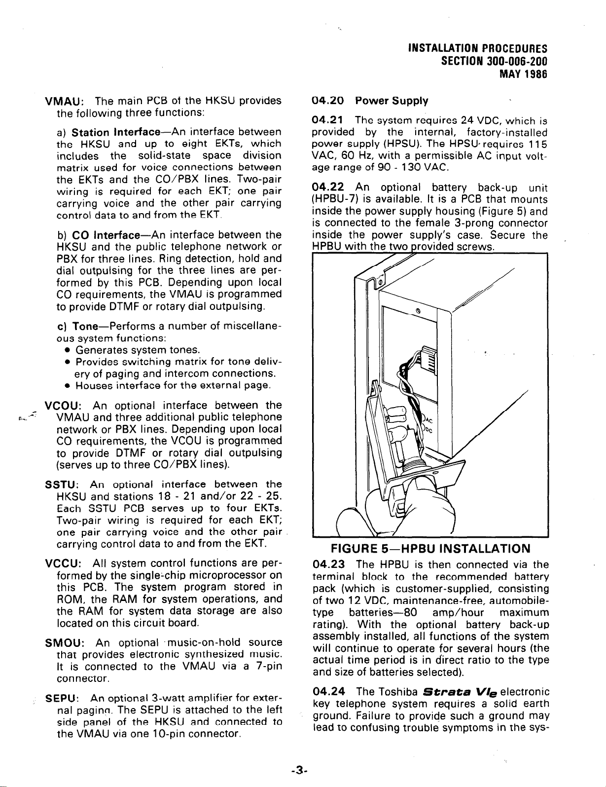
04.21
The system requires 24 VDC, which is
Supply
provided by the internal, factory-installed
power supply (HPSU). The HPSU requires 115
VAC, 60 Hz, with a permissible AC input volt-
age range of 90 - 130 VAC.
04.22 An optional battery back-up unit
(HPBU-7) is available. It is a PCB that mounts
inside the power supply housing (Figure 5) and
is connected to the female 3-prong connector
inside the power SUPP~Y’S case. Secure the
/
/
,
6,. -47
VCOU:
VMAU and three additional public telephone
An optional interface between the
network or PBX lines. Depending upon local
CO requirements, the VCOU is programmed
to provide DTMF or rotary dial outpulsing
(serves up to three CO/PBX lines).
SSTU:
An optional interface between the
HKSU and stations 18 - 21 and/or 22 - 25.
Each SSTU PCB serves up to four EKTs.
Two-pair wiring is required for each EKT;
one pair carrying voice and the other pair
carrying control data to and from the EKT.
VCCU: All system control functions are per-
formed by the singlechip microprocessor on
this PCB. The system program stored in
ROM, the RAM for system operations, and
the RAM for system data storage are also
located on this circuit board.
SMOU: An optional .music-on-hold source
that provides electronic synthesized music.
It is connected to the VMAU via a 7-pin
connector.
SEPU: An optional 3-watt amplifier for exter-
nal paging. The SEPU is attached to the left
side panel of the HKSU and connected to
the VMAU via one 1 O-pin connector.
i
/
FIGURE 5-HPBU INSTALLATION
04.23 The HPBU is then connected via the
terminal block to the recommended battery
pack (which is customer-supplied, consisting
of two 12 VDC, maintenance-free, automobiletype batteries-80 amp/hour
rating). With the optional battery back-up
assembly installed, all functions of the system
will continue to operate for several hours (the
actual time period is in direct ratio to the type
and size of batteries selected).
04.24 The Toshiba
Strata V/e
key telephone system requires a solid earth
ground. Failure to provide such a ground may
lead to confusing trouble symptoms in the sys-
maximum
electronic
-3-
Page 24
INSTALLATION PROCEDURES
SECTION 300-006-200
MAY 1966
tern and, in extreme cases, circuit board fail-
ure. In most installations (within the continen-
tal United States), the ground provided by the
“third wire ground” at the commercial power
outlet will be satisfactory for all
Strata V/=
requirements. However, in a small percentage
of installations, this ground may be installed
incorrectly. Therefore, prior to installing a system, the third wire ground must be tested for
continuity by either measuring the resistance
between the third prong terminal (earth
ground) and a metal cold water pipe, or by
king a commercially available
indicator. If neither procedure is
the test procedures outlined
earth ground
possible, then
in Paragraph
04.30 should be performed.
WARNING!
Hazardous voltage is exposed during the
following test. Use great care when
working with AC voltage.
04.30 Test
Procedures
1) Obtain a suitable voltmeter and set it for a
possible reading of up to 250 VAC.
2) Connect the meter probes between the two
main AC voltage points on the wall outlet. The
reading obtained should be 90 - 130 VAC.
should be obtained. If a reading of more than 1
ohm is obtained, the outlet is
not
adequately
grounded.
8) If the above tests show the outlet is improperly grounded, that condition should be corrected by a qualified electrician (per Article
250 of the National Electrical Code) before the
Strata
system is connected.
04.31 Ensure that the power switch on the
HPSU is OFF, then plug the power supply into
the 1 15 VAC outlet.
04.40 PCB
Installation
04.41 The VMAU and VCCU are factory-in-
stalled in the HKSU.
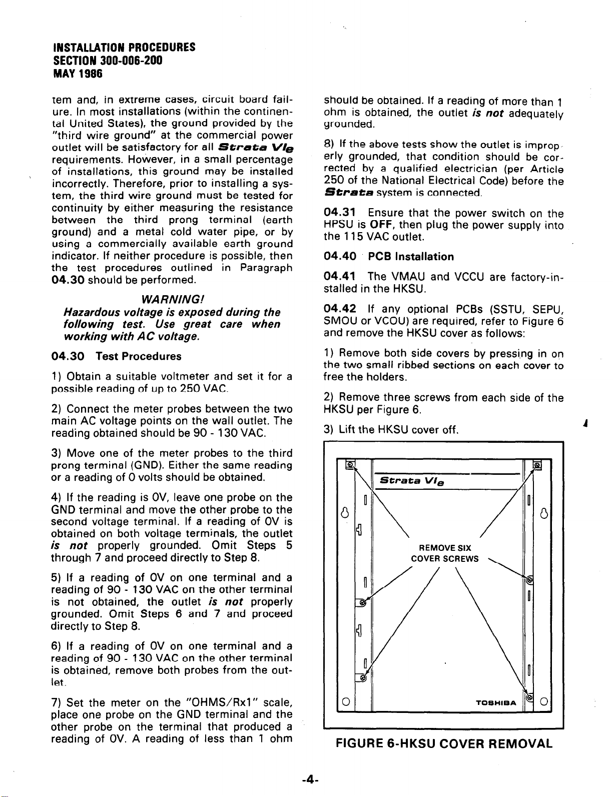
04.42 If any optional PCBs (SSTU, SEPU,
SMOU or VCOU) are required, refer to Figure 6
and remove the HKSU cover as follows:
1) Remove both side covers by pressi.ng in on
the two small ribbed sections on each cover to
free the holders.
2) Remove three screws from each side of the
HKSU per Figure 6.
3) Lift the HKSU cover off.
A
3) Move one of the meter probes to the third
prong terminal (GND). Either the same reading
or a reading of 0 volts should be obtained.
4) If the reading is OV, leave one probe on the
GND terminal and move the other probe to the
second voltage terminal. If a reading of OV is
obtained on both voltage terminals, the outlet
is
not
properly grounded. Omit Steps 5
through 7 and proceed directly to Step 8.
5) If a reading of OV on one terminal and a
reading of 90 - 130 VAC on the other terminal
is not obtained, the outlet is
not
properly
grounded. Omit Steps 6 and 7 and proceed
directly to Step 8.
6) If a reading of OV on one terminal and a
reading of 90 - 130 VAC on the other terminal
is obtained, remove both probes from the out-
let.
7) Set the meter on the “OHMWRxl” scale,
place one probe on the GND terminal and the
other probe on the terminal that produced a
reading of OV. A reading of less than 1 ohm
REMOVE SIX
COVER SCREWS
0
TOSHlEA
FIGURE 6-HKSU COVER REMOVAL
Page 25
INSTALLATION PROCEDURES
SECTION 300-006-200
MAY 1986
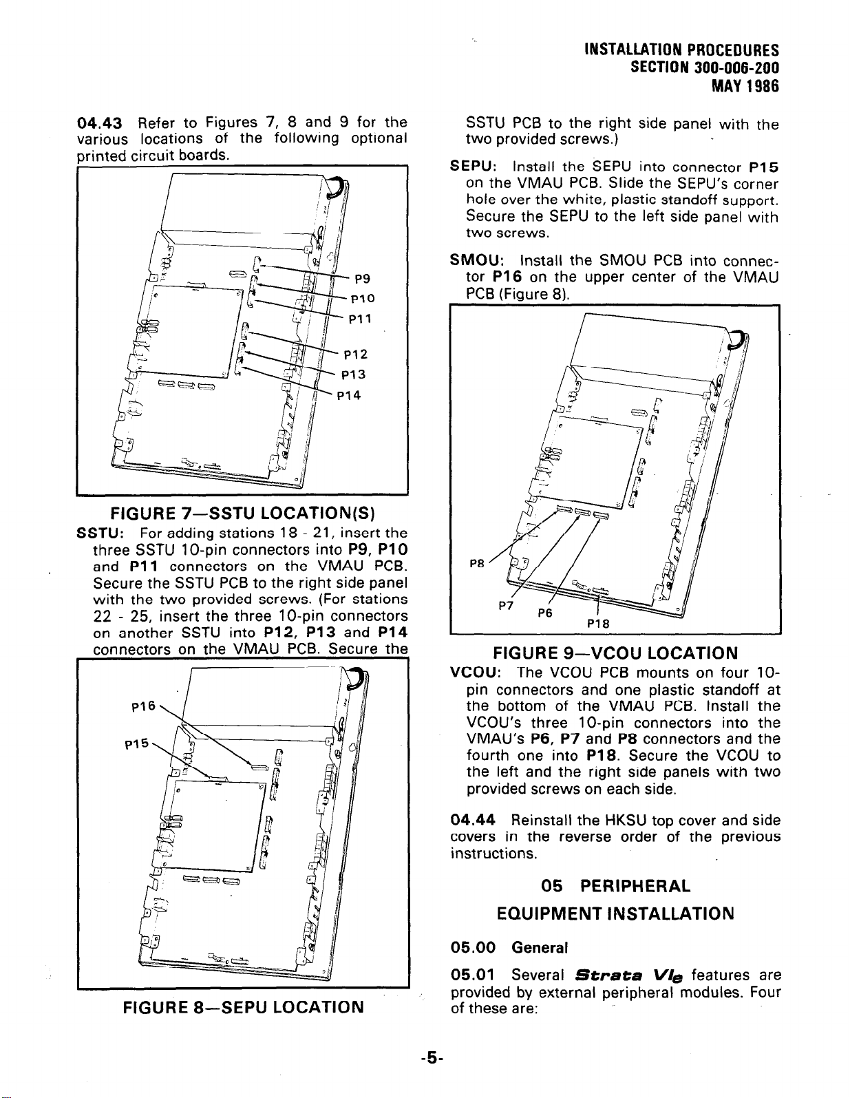
04.43 Refer to Figures 7, 8 and 9 for the
various locations of the following optional
rinted circuit boards.
FIGURE 7-SSTU LOCATION(S)
SSTU:
three SSTU lo-pin connectors into P9, PlO
and Pll connectors on the VMAU PCB.
Secure the SSTU PCB to the right side panel
with the two provided screws. (For stations
22 - 25, insert the three lo-pin connectors
on another SSTU into P12, P13 and P14
connectors on the VMAU PCB. Secure the
For adding stations 18 - 21, insert the
SSTU PCB to the right side panel with the
two provided screws.)
SEPU: Install the SEPU into connector P15
on the VMAU PCB. Slide the SEPU’s corner
hole over the white, plastic standoff support.
Secure the SEPU to the left side panel with
two screws.
SMOU: Install the SMOU PCB into connec-
tor
P16
on the upper center of the VMAU
PCB (Fiaure 81.
P8
P18
FIGURE
VCOU:
pin connectors and one plastic standoff at
the bottom of the VMAU PCB. Install the
VCOU’s three lo-pin connectors into the
VMAU’s P6, P7 and P8 connectors and the
fourth one into
the left and the right side panels with two
provided screws on each side.
The VCOU PCB mounts on four lo-
9-VCOU LOCATION
P18.
Secure the VCOU to
FIGURE 8-SEPU LOCATION
04.44 Reinstall the HKSU top cover and side
covers in the reverse order of the previous
instructions.
05 PERIPHERAL
EQUIPMENT INSTALLATION
05.00
05.01 Several
provided by external
of these are:
-5-
General
Strata V/e
peripheral modules. Four
features are
Page 26
INSTALLATION PROCEDURES
SECTION 300-006-200
MAY 1966
HOXB
and
HSMB
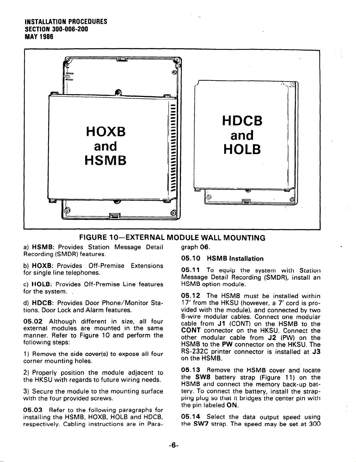
FIGURE lo--EXTERNAL MODULE WALL MOUNTING
a) HSMB: Provides Station Message Detail
Recording (SMDR) features.
b) HOXB: Provides Off-Premise Extensions
for single line telephones.
c) HOLB: Provides Off-Premise Line features
for the system.
d) HDCB: Provides Door Phone/Monitor Stations, Door Lock and Alarm features.
05.02 Although different in size, all four
external modules are mounted in the same
manner. Refer to Figure 10 and perform the
following steps:
1) Remove the side cover(s) to expose all four
corner mounting holes.
2) Properly position the module adjacent to
the HKSU with regards to future wiring needs.
3) Secure the module to the mounting surface
with the four provided screws.
05.03 Refer to the
installing the HSMB,
respectively. Cabling
following paragraphs for
HOXB, HOLB and HDCB,
instructions are in Para-
graph 06.
05.10
05.11
Message Detail Recording (SMDR), install an
HSMB option module.
05.12 The HSMB must be installed within
17’ from the HKSU (however, a 7’ cord is pro-
vided with the module), and connected by two
B-wire modular cables. Connect one modular
cable from
CONT connector on the HKSU. Connect the
other modular cable from J2 (PW) on the
HSMB to the PW connector on the HKSU. The
RS-232C printer connector is installed at J3
on the HSMB.
05.13 Remove the HSMB cover and locate
the SW8 battery strap (Figure 11) on the
HSMB and connect the memory back-up battery. To connect the battery, install the strapping plug so that it bridges the center pin with
the pin labeled ON.
05.14 Select the data output speed using
the SW7 strap. The speed may be set at 300
HSMB
To equip the system with Station
Installation
Jl
(CONT) on the HSMB to the
-6-
Page 27
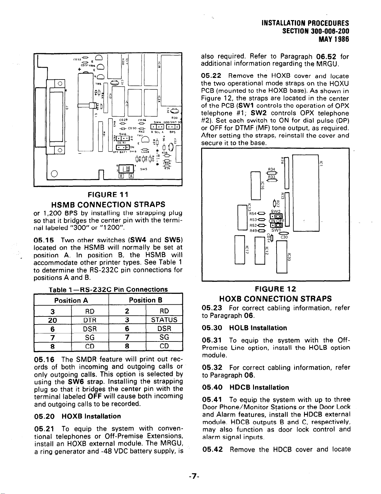
FIGURE 11
HSMB CONNECTION STRAPS
or 1,200 BPS by installing the strapping plug
so that it bridges the center pin with the termi-
nal labeled “300” or “1200”.
INSTALLATION PROCEDURES
SECTION 300-006-200
MAY 1986
also required. Refer to Paragraph 06.52 for
additional information regarding the MRGU.
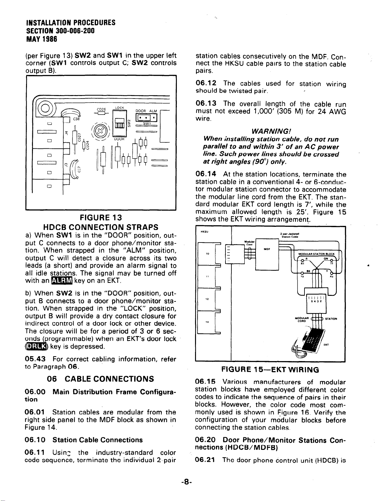
05.22 Remove the HOXB cover and locate
the two operational mode straps on the HOXU
PCB (mounted to the HOXB base). As shown in
Figure 12, the straps are located in the center
of the PCB
telephone #l; SW2 controls OPX telephone
#2). Set each switch to ON for dial pulse (DP)
or OFF for DTMF (MF) tone output, as required.
After setting the straps, reinstall the cover and
secure it to the base.
(SW1
controls the operation of OPX
05.15
located on the HSMB will normally be set at
position A. In position B, the HSMB will
accommodate other printer types. See Table 1
to determine the RS-232C pin connections for
positions A and B.
05.16
ords of both incoming and outgoing calls or
only outgoing calls. This option is selected by
using the SW6 strap. Installing the strapping
plug so that it bridges the center pin with the
terminal labeled
and outgoing calls to be recorded.
05.20 HOXB
05.21
tional telephones or Off-Premise Extensions,
install an HOXB external module. The MRGU,
a ring generator and -48 VDC battery supply, is
Two other switches (SW4 and SW5)
Table 1 -RS-232C
The SMDR feature will print out rec-
OFF
Installation
To equip the system with conven-
Pin Connections
will cause both incoming
FIGURE 12
HOXB CONNECTION STRAPS
05.23 For correct cabling information, refer
to Paragraph 06.
05.30 HOLB
05.31
Premise Line option, install the HOLB option
module.
05.32 For correct cabling
to Paragraph 06.
05.40
05.41
Door Phone/Monitor Stations or the Door Lock
and Alarm features, install the HDCB external
module. HDCB outputs B and C, respectively,
may also function as door lock control and
alarm signal inputs.
05.42 Remove the HDCB cover and locate
To equip the system with the Off-
HdCB Installation
To equip the system with up to three
installation
information, refer
-7-
Page 28
INSTALLATION PROCEDURES
SECTION 300-006-200
MAY 1986
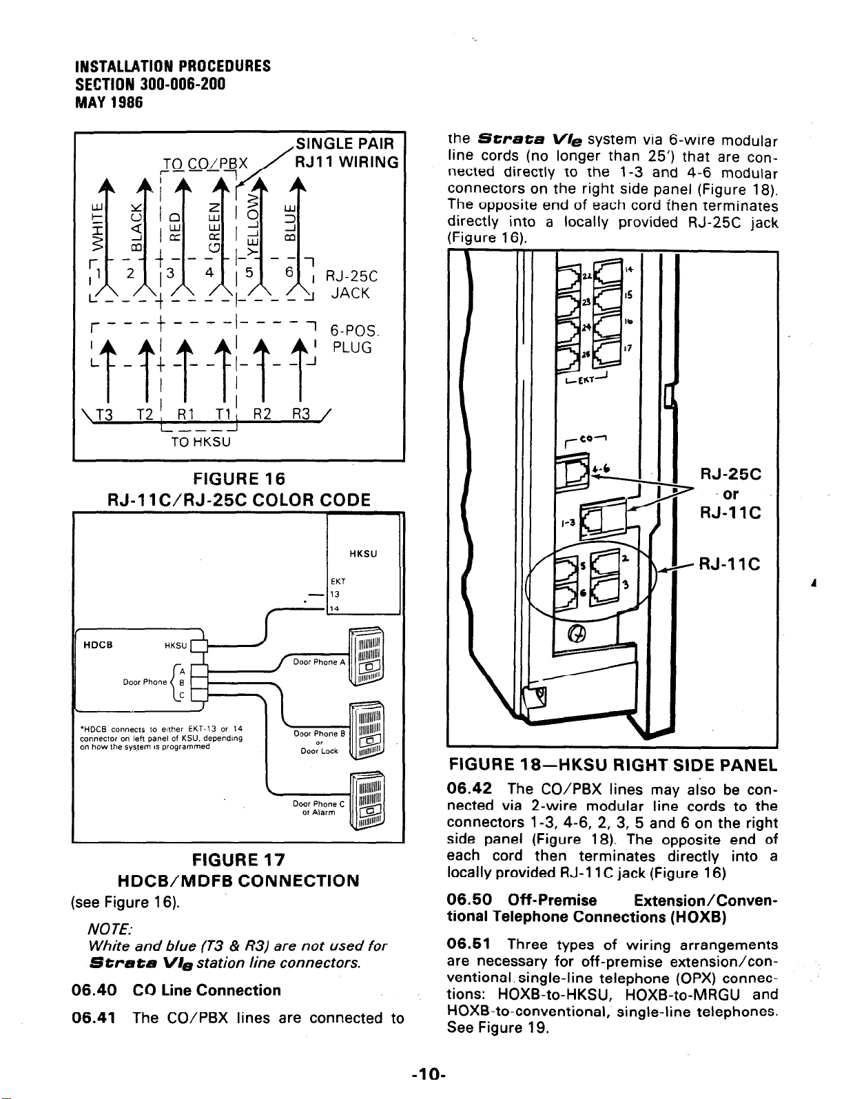
(per Figure
corner
nlltnrrt I31
(SW1
13) SW2
controls output C;
and
SW1
in the upper left
SW2
controls
FIGURE 13
HlXB CONNECTION STRAPS
a) When
put C connects to a door phone/monitor station. When strapped in the “ALM” position,
output C will detect a closure across its two
leads (a short) and provide an alarm signal to
all idle stations. The signal may be turned off
with an m key on an EKT.
SW1
is in the “DOOR” position, out-
station cables consecutively on the MDF. Connect the HKSU cable pairs to the station cable
pairs.
06.12 The cables used for station wiring
should be twisted pair.
06.13 The overall length of the cable run
must not exceed 1,000’ (305 M) for 24 AWG
wire.
WARNING!
When installing station cable, do not run
parallel to and within 3’ of an AC power
line. Such power lines should be crossed
at right angles (90”) only.
06.14
station cable in a conventional 4- or 6-conductor modular station connector to accommodate
the modular line cord from the EKT. The standard modular EKT cord length is 7’, while the
maximum allowed length is -25’. Figure 15
shows the EKT wiring arrangement.
“IO”
At the station locations, terminate the
b) When SW2 is in the “DOOR” position, output 6 connects to a door phone/monitor station. When strapped in the “LOCK” position,
output 6 will provide a dry contact closure for
indirect control of a door lock or other device.
The closure will be for a period of 3 or 6 seconds ( rogrammable) when an EKT’s door lock
(m$, key is depressed.
05.43 For correct cabling information, refer
to Paragraph 06.
06 CABLE CONNECTIONS
06.00
tion
06.01
right side panel to the MDF block as shown in
Figure 14.’
06. I 0
06.1 I
code sequence, terminate the individual
Main Distribution Frame Configura-
Station cables are modular from the
Station Cable Connections
Usin:
the industry-standard
color
2-pair
FIGURE 15-EKT WIRING
06.15
station blocks have employed different color
codes to indicate the sequence of pairs in their
blocks. However, the color code most commonly used is shown in Figure 16. Verify the
configuration of your modular blocks before
connecting the station cables.
06.20
nections (HDCB/MDFB)
06.21
Various manufacturers of modular
Door Phone/Monitor Stations Con-
The door phone dontrol unit (HDCB) is
-B-
Page 29

External
Music
Source
_
lNSTALiATlON PROCEDURES
SECTION 300-006-200
MAY 1986
HKSU
---+ HOXB 1
External
Speaker
r
Standard Phone
Standard Phone
FIGURE 14-SYSTEM DIAGRAM
connected to the HKSU, via a standard EKT
modular connector, at the EKT #13 or #14
modular connector (program-controlled).
06.22
C),
door phone units (MDFBs). Outputs B and C
can also be used for Door Lock and Alarm features, respectively.
06.23
(MDFB) is connected to the HDCB via a Z-wire
modular connector at the- HDCB and a split
ring connector at the MDFB using screw terminals 1 and 2 (Ll and L2 are not used).
The HDCB has three outputs (A, B and
which are modular connectors for three
Each door Dhone/monitor station
I
I
NOTE:
When using outputs B and C for Door
Lock and Alarm features, respectively, an
appropriate modular connector must be
used to interface the HDCB to the door
lock and alarm system devices.
06.24 Figure 17 shows the HDCB and MDFB
wiring arrangement.
06.30 Intercom Code Assignment
06.31 Intercom codes (station numbers) are
assigned permanently to specific cable appearantes in
.’
cables are connected to the proper terminals
Strata V/ez
.
Make sure the station
_EKT
EKT
CO/PBX
*
-9-
Page 30
INSTALLATION PROCEDURES
SECTION 300-006-200
MAY 1986
---
TO HKSU
SINGLE PAIR
RJll WIRING
the
Strata V/e
system via 6-wire modular
line cords (no longer than 25’) that are connected directly to the 1-3 and 4-6 modular
connectors on the right side panel (Figure 18).
The opposite end of each cord Ehen terminates
directly into a locally provided RJ-25C iack
Jre 1
I.
61
FIGURE 16
RJ-11 C/RJ-25C COLOR CODE
HKSU
EKT
- 13
.
‘HDCB connects to either EKT-13 or 14
connector on left panel of KSU. dependmg
on how the syswm 15 programmed
FIGURE 17
HDCB/MDFB CONNECTION
(see
Figure 16).
NOTE:
White and blue (T3 & R3) are not used for
Strata
06.40 Cc)
06.41 The CO/PBX lines are connected to
VI9
station line connectors.
Line Connection
RJ-25C
*
-or
RJ-11C
e RJ-11C
FIGURE 18-HKSU RIGHT SIDE PANEL
06.42
nected via 2-wire modular line cords to the
connectors l-3, 4-6, 2, 3, 5 and 6 on the right
side panel (Figure 18). The opposite end of
each cord then terminates directly into a
locally provided RJ-11 C jack (Figure 16)
06.60
The CO/PBX lines may also be con-
Off-Premise
ExtensionIConven-
tional Telephone Connections (HOXB)
06.51
are necessary for off-premise extension/conventional. single-line telephone (OPX) connections: HOXB-to-HKSU, HOXB-to-MRGU and
HOXB-to-conventional, single-line telephones.
See Figure 19.
Three types of wiring arrangements
A
-lO-
Page 31

1
TBZ
- -
A
HOXB
FIGURE 19-HOXB WIRING
1) HOXB-to-HKSU connections are made via a
4-wire modular cord from station 20 (on the
Lr
’
HKSU) to the HOXB terminal strip (TB3) voice
and control data terminals. A station 21 voiceonly connection is re-
quired if a second OPX
circuit is desired.
TB3
_ _ _ _ _ -
J
NOTE. For OPX operafion. the control data
crrcuircommecrion for EKT21 isnotrequired.
L-l
06.60
06.61 When using the HOLB unit, CO lines
INSTALLATION PROCEDURES
SECTION 300-006-200
are
FCC registered
with a facility interface code of OL 13A.
. _
lf an alternate DC
supply/ritig
ator is to be used,
con tact your Toshiba
supplier for details.
3)
HOXB-to-conventional single-line telephone
connections are made
from the telephone to
the HOXB terminal strip
I
(TB2) with industry-
standard 2-, 4- or 6-wire
cable.
NOTE:
The HOXB requires a
negative DC voltage;
therefore, the main
HKSU power cannot
be used (it is +24
volts).
Off-Premise Line Connection
MAY 1986
gener-
2) HOXB-to-MRGU connections are made from
the MRGU output termi-
nal strip to the HOXB
terminal strip (TBl).
a) Connect 80 VAC,
25
Hz, output on the
MRGU to the “BELL”
input on the HOXB.
b) Connect the -48
VDC and 0 V battery
terminals on
units,
observing the
both
correct polarity.
c) Connect FG to FG
on both units.
IMPORTANT FCC
INFOhMA TION:
HOXB and MRGU
Standerd
Phone
ul
I
CO/PBX
c
FIGURE 20-HOLB WIRING
-ll-
Page 32

INSTALLATION PROCEDURES
SECTION 300-006-200
MAY 1986
1, 2 and 3 (RJ-25C) or 1, 2
connected to the CO 1,
or
3
2, 3 (or CO
(RJ-1
1C)
1, CO 2 or
are
CO 3) in connectors on the HOLB unit. Then,
connect a g-wire cable from the HOLB to the
CO l-3 connector on the right side panel of
the HKSU. An 8-wire factory-provided cable is
connected from the HOLB l-3 connector (on
the HKSU left side panel) to the HOLB unit.
Connect up to three conventional, single-line
telephones to the modular connectors (TEL 1,
2, 3) on the HOLB (Figure 20).
06.62 A similar procedure is followed if a
second HOLB unit is to be connected to the
HOLB 4-6 connector.
06.63 A single answering machine connected to OPL circuit #l will also serve OPL
circuit #2 and/or #3. An HOLB is equipped
with a chain of relay contacts (Figure 20) that,
operating under software control via
0#9, can
switch incoming calls on CO circuits
Program
#2 and/or #3 to the OPL #l output circuit.
This hunting operates only during NITE service
and can occur only with the three circuits
appearing on the PCB; and it always occurs
from #3 and/or #2 to #l. (It is not possible to
chain two HOLB PCBs together.)
06.70
Station Message Detail Recording
Connections
06.71
If the system is to be equipped with
Station Message Detail Recording (SMDR), an
HSMB option module must be connected to
the system (via two factory-provided 8-wire
cables) from the HSMB’s
CONT
and
PW
con-
nectors. Printer types known to be compatible
with this system are:
Texas Instruments Model 743/745
OKI Data Model 82A
Texas Instruments 743./745 .
FG 1
RD 3 3 RD
HSMB ‘z=$ ;
CD 8 - 8CD
DTR 20
FG 1 1 FG
RD 3
HSMB OS* 6
SG 7 7 SG
CD 8
DTR 20
“Supewsory
- p
OKI Data 82A
Send Data-cable modlflcatlon required.
1
FG
_ 6 DSR
7 SG Printer
20 DTR
.
3RD
6 DSR
8 CD
11 SSD’
Printer
FIGURE 21
HSMB/PRINTER CABLING
07.01
phones (EKTs) may be used in the
V/e
available as a speakerphone or with handsfree
answerback (HFU) only. The two models, identical in appearance, are equipped with four
permanently dedicated keys and 10 line/feature keys.
handsfree on intercom calls only. The lo-key
BLF EKT with speakerphone (Figure 23) is similar in appearance to the lo-key, but with a
Busy Lamp Field (BLF).
Six different Electronic Key Tele-
Strata
system. The lo-key EKT (Figure 22) is
The HFU model may be answered
1
06.72 The data output is in 7-bit ASCII code
with one start bit,
one
parity bit (even parity)
and one stop bit. Figure 21 shows the detailed
connections for the printers listed above.
06.73 Verify that the RS-232C output cable
is connected to the PCB with the proper pin-
out connections (A or B), the battery strap is
ON, and the data speed and incoming/outgoing call options are selected per Paragraph
06.50.
07 EKT INFORMATION
07.00
General
-12-
FIGURE
22-IO-key
EKT
Page 33

INSTALLATION PROCEDURES
SECTION 300-006-200
MAY 1986
FIGURE 23-IO-key BLF EKT
07.02 Three additional EKTs that are very
similar to the lo-key, but with 10 additional
keys, are also available. The 20-key EKT (Figure 24) is available as a speakerphone or with
handsfree answerback only. The two models,
identical in appearance, are equipped with
four permanently dedicated keys and 20 line/
feature keys. The HFU model may be answered
handsfree on intercom calls only. A 20-key
Liquid Crystal Display (LCD) EKT (Figure 25),
which has a 32-character alphanumeric dis-
play, is also available.
07.03 All EKTs share the same dimensions:
Height: 3.87” (98.5 mm)
Width: 7.0” (178 mm)
Depth:
9.0” (229 mm)
FIGURE 25-20-key LCD EKT
07.04
line/feature keys in addition to a push-button
dial pad. Up to six of the keys are utilized for
CO/PBX lines: one for intercom access and
the remaining keys are used for feature opera-
tion. System software assignments permit
wide variation to the feature keys on all six
EKTs.
07.05 The principal components of the lokey electronic key telephone are: handset, dial
pad, handsfree answerback HFU) microphone,
a microphone control key
m key, two ringing/speaker volume con-
trols, one intercom key, nine CO/PBX line or
feature keys. LED indicators are rovided for
all keys except the m and
With the exception of the four permanently
dedicated keys, the feature keys can be
assigned to any one of several keystrip modes
by programming. The identical EKT is also
available as a speakerphone.
07.06 The lo-key BLF EKT provides the
same features as those listed in Paragraph
07.05, plus an LED indication showing which
stations are in use.
Each is equipped with either 14 or 24
hn.
speaker and
l
b
keys.
FIGURE 24-20-key EKT
07.07 The 20-key EKT provides the same
features as those listed in the above two para-
graphs, plus 10 additional feature keys.
07.08 A 20-key Liquid Crystal Display (LCD)
EKT, incorporating the same features as those
listed for the above EKTs, may be located at
any or all of the stations. The 32character
alphanumeric display provides an accurate
-13-
Page 34

INSTALLATION PROCEDURES
SEETION 300-006-200
MAY 1986
clock/calendar in its idle state. In use, the display provides elapsed time of call (incoming or
outgoing), dialed number, calling station or CO
line.
07.09 All EKTs feature modular handset
cords and are connected to the system via 4conductor modular line cords. In addition, each
EKT model may be used at any or all stations.
07.10
07.11
manner, and they may be mounted on a wall
or any other flat, vertical surface to which the
base can be secured. When selecting the
mounting site, consider the EKT’s weight and
the additional stresses to which the mounting
will be subjected.
07.12 Mounting screws or mollies, appropriate for the surface on which the telephone is
to be secured, must be provided by the
installer.
07.13 Locking tabs secure the EKT’s base.
The direction in which the base is attached to
the EKT determines whether it will be used as
a desk unit or wall unit (it is factory-configured
as a desk unit). Disengage the locking tabs by
pushing downward on the base (Figure 26)
and then rotate the base 180” and insert it into
the lower four locking tabs.
EKT Wall Mounting
All EKTs are mounted in the same
I
FIGURE 27-EKT WIRE
07.15 Secure the unit to the desired wall
site. (Use dimensions shown in l%guro 27 to
position the unit.)
07.16 Route the tail cord through the holes
in the base and secure the EKT (Figure 28).
ACCESS
A
FIGURE 26-REMOVING EKT BASE
07.14
the knockouts are appropriate for the tail cord
route, and then cut them out.
Refer to Figure 27, choose which of
FIGURE 28-EKT WIRE ROUTING
07.17
able from your Toshiba supplier, and it is suggested that this cord be used when wall
mounting an EKT.
07.18 Remove the handset hanger and ininsert it in the upper hole as shown in Figure
29. Note that the hanger fits in the notch in
the handset.
An optional 13’ handset cord is avail-
-14-
Page 35

INSTALLATION
PROCEDURES
SECTION 300-006-200
MAY 1966
NOTE.
Do not initialize if using a preprogrammed, battery-protected VCCU.
FIGURE 29-HANDSET HANGER
07.20 EKT Connections
07.21
Connect the appropriate length line
cord to the modular connector, route the cord
to the EKT and connect to the EKT modular
jack. Test the EKT per Paragraph 09.
08 SYSTEM POWER-UP INITIALIZE
08.00
08.01
_-
system data assignments stored in ROM that
can be entered at any time by performing the
initialize sequence outlined below. The system
must be initialized when it is first installed or
whenever the VCCU PCB is changed. This will
allow the system to be tested and any faults to
be corrected before time is spent on program-
ming.
General
Stasta V/e
has a list of standard
08.02
Refer to Figure 30 and verify that the
battery on the VCCU is connected to ensure
that data changes entered after initialization
will not be lost due to power failure.
NOTE:
The SET LED will not function if the VCCU
battery is not connected.
08.03
To initialize the system data memory,
refer to Figure 31 and perform the following:
POWER
FIGURE 31 -INITIALIZE SWITCH
1) Place the system power switch
the ON position.
2)
Depress the
INT
switch on the left side
panel, and hold it in.
(POW)
in
IC22 IC13
FIGURE 30-VCCU BAlTERY STRAP
3)
Depress the SET switch and allow it to lock.
l
SET LED goes on.
l
Station 17: All LEDs except SPKR and
MIC flash continuously.
4) Depress and release the
l
SET LED goes off.
l
Station 17: All LEDs go off.
SET
switch again.
5) Release the INT switch.
6) Cycle the power sw.itch OFF and ON.
08.10
08.11
Clearing Automatic Dialing
The Automatic Dialing memory will
contain random numbers when the system is
powered up initially. _The memory; therefore,
Page 36

INSTALLATION PROCEDURES
SECTION 300-006-200
MAY
1986
must be cleared to prevent meaningless numbers from being dialed.
IMPORTANT!
Station 17 may be equipped with either
a
1
O-key
or a 20-key EKT. Prior to per-
forming the procedure that follows,
refer to Paragraph OZ.ZO/Figure I, Programming Procedures, Section 300-006-
300, for instructions on using a I O-key
EK T for programming.
08.12
To clear the Automatic Dialing (-Sys-
tern and -Station) memory (up to 40 numbers),
proceed as follows:
1) Lock in the
l
Station 17: All LEDs except SPKR and
SET
switch on the HKSU.
MIC flash continuously.
2)
Depress the m key on station 17.
l
SPKR LED lights steadily.
3) Dial ~~~ on the dial pad.
l
SPKR LED flashes continuously.
4) Depress the mm m m keys,
respectively.
l
The corresponding LEDs light.
Depress the m key.
5)
l
All station 17 LEDs (except REP) go off.
l
The SET LED and REP LED on station 17
go off.
08.20
08.21
SMDR Real-Time Clock Adjustment
One of the functions of the HSMB is
to provide a calendar and clock for showing
time, date and duration of recorded calls. This
clock and calendar must be set when the system is first placed into service.
08.22 The HSMB is equipped with a battery
to protect the clock and calendar settings in
event of a power failure. Ensure that the
HSMB battery
(6AlT)
strap is in the ON posi-
tion (see Figure 1 1).
08.23 The HSMB will automatically adjust
for 30- and 28-day months and leap year.
08.24 The HSMB is equipped with three
switches and two LEDs (Figure 32). Looking
from top to bottom,
the functions of the
switches are as follows:
STR:
Writes data into memory once it is
properly displayed.
MOD:
depressions of the
Selects items to be adjusted. Multiple
MOD
switch will cause
item numbers to be displayed sequentially
by LED #l. The possible displays are:
1
6) Release the
HSM3 SWITCHES and LEDs
SET
switch on the HKSU:
IN MC0
0 R45
FIGURE 32
R49 -
RSO e
RSI 0
Off
1 = year
2 = month
3 = day
4 = hour
5 = minute
6 = start
INC: Selects the data (hour, minute, day,
etc.) for the item number selected by the
MOD
#2 displays data selected by the
switch and displayed by LED #l. LED
INC
l
Depressing the
INC
switch once incre-
switch.
ments data by 1.
l
Depressing and holding the INC switch
causes data to increase continuously
until the
INC
switch is released.
08.25 To set clock and calendar:
1) Verify that the battery is connected on the
HSMB (Figure 32).
2) Depress the MOD switch once.
l
LED #l displays 1 (year).
-16-
Page 37

INSTALLATION PROCEDURES
SECTION 300-006-200
MAY
1986
--_
l
LED #2 displays current data.
3) Use the INC switch to correct data in LED
#2 display.
4) Depress the
l
LED #l displays 2 (month).
l
LED #2 displays current data.
5) Use the
MOD
INC
switch once.
switch to correct data in LED
#2 display.
6) Depress the
l
LED #l displays 3 (day).
l
LED #2 displays current data.
7) Use the
MOD
INC
switch once.
switch to correct data in LED
#2 display.
8) Depress the
l
LED #l displays 4 (hour).
l
LED #2 displays current data
MOD
switch once.
9) Use the INC switch to correct data in LED
#2 display.
10) Depress the
l
LED #l displays 5 (minute).
l
LED #2 displays current data.
a-
11) Use the INC switch to correct data in LED
#2 displav.
.
12) Depress the
l
LED #l displays 6 (start).
l
LED #2 has no display.
13) Slide the
to
OFF.
MOD
MOD
STR
switch once.
switch once.
switch to ON and then back
. LEDs go off.
l
Data is transferred to working memory
and time keeping starts.
09 SYSTEM TEST PROCEDURES
09.00
09.01
tions, and confirm the proper functioning of
the EKT itself, perform the following test
procedures at each station. Begin with the
lowest numbered station and continue through
all stations.
09.02 With handset on-hook:
a) Depress the m key.
b) Adjust speaker volume with the volume
control on the right-hand side of the EKT.
c) Depress the m key.
d) Dial any digit (I- D
tone will stop.
e) Depress the m key.
f) Continue to depress each m key in order
on every EKT; the following should occur:
EKT Functional Check
In order to verify basic system func-
l
INT LED: l-use flash.
l
SPKR LED: on steady.
l
MIC LED: on steady.
l
Listen for intercom dial tone via the EKT
speaker.
l
CO 1 LED: l-use flash.
l
SPKR & MIC LEDs: on steady.
l
Listen for CO/PBX dial tone via the EKT
speaker.
on the dial pad and dial
l
Listen for circuit break followed by dial
tone after approximately 2 seconds.
l
CO LED: l-use flash.
l
SPKR & MIC LEDs: on steady.
l
Listen for CO/PBX dial tone via the EKT
speaker.
’
NOTE.
If LED #1 is changed to OFF before STR
is operated, existing data will not be
changed regardless of adjustments made
in previous steps.
08.30
Program Listing
08.31 The HSMB has the capability to retrieve current customer data from memory and
output it to the SMDR printer.
08.32 See Section 200-006-300,
ming Procedures
for printout method and for-
Program-
mat.
-17-
NOTE:
If no CO/PBX facility is connected to a
m key, dial tone will not be heard but the
LED is still functional.
g)
When CO testing is complete on each EKT,
continue EKT test by depressing them key.
l
SPKR & MIC LEDs: off.
l
EKT speaker off.
.
h) Depress the m key.
l
DND LED: on.
i) Depress the m key.
. DND LED: off.
-
Page 38

INSTALIATIDN PROCEDURES
SECTION 300-006-200
MAY1986
j) Depress the m key.
l
CO 1 LED: l-use flash.
l
SPKR & MIC LEDs: on steady.
l
Listen for CO/PBX dial tone via the EKT
speaker.
k) Depress the m key.
l
CO 1 LED: i-hold flash.
l
Speaker off (no dial tone).
. SPKR & MlC LEDs: off.
I) Depress the m key.
l
CO 1 LED: l-use flash.
l
SPKR & MIC LEDs: on steady.
l
Listen for CO/PBX dial tone via the EKT
speaker.
m) Depress the m key.
l
CO 1 LED: Conference call fiash rate.
l
Dial tone continues.
n) Depress the m and m keys.
. CO 1 LED: off.
. SPKR & MIC LEDs: off.
l
Dial tone: off.
o) Call the EKT that is being tested from
another station.
l
Listen for caller’s voice via called EKT’s
speaker after the single tone signal.
l
Called station’s INT LED: l-called flash.
Dial 4 at calling station.
P)
l
Tone signalling heard via the called sta-
tion’s speaker.
Adjust tone signalling volume with volume
4)
control on the rear left-hand side of the EKT
being tested.
e INT LED: l-use flash.
l
SPKR & MIC LEDs: on steady.
v) Tap the EKT microphone and verify that the
sound can be heard via the called EKT’s
speaker.
w) Depress the m key while tapping the
microphone and verify that the sound cannot
be heard via called EKT’s speaker.
l
MIC LED: off while the m key is de-
pressed.
x) Depress the w key.
. INT LED: off.
. SPKR & MIC LEDs: off.
y) Depress the m key.
l
INT LED: l-use flash rate.
l
SPKR & MIC LEDs: on steady.
l
Listen for intercom dial tone via the EKT
speaker.
z) Call a busy station.
l
Listen for busy tone.
aa) Depress the m key.
l
Dial tone should be heard for 2 seconds
followed by busy tone again.
bb) Depress the m key.
. SPKR & MIC LEDs: off.
. INT LED: off.
cc) Depress the m key.
l
INT LED: l-use flash rate.
l
SPKR & MIC LEDs: on steady.
l
Listen for intercom dial tone via the EKT
speaker.
r) Depress the m key.
l
INT LED: l-use flash.
l
SPKR & MIC LEDs: on steady.
l
Listen for intercom dial tone via the EKT
’
speaker.
s) Lift handset.
. SPKR & MIC LEDs: off.
l
Speaker off.
l
Listen for dial tone via handset receiver.
t) Call another station and talk into the handset transmitter.
l
Verify that your voice can be heard via
the called EKT’s speaker.
u) Hold down them key, and set the handset back on-hook.
-1s
dd) Dial 00 to cancel the ACB feature.
l
Dial tone should be heard for 2 seconds
followed by busy tone.
ee) Depress the m key.
. SPKR &
MIC LEDs:
off.
. INT LED: off
09.03 This completes the station functional
check for the EKTs; repeat the procedure for all
EKTs in the system.
09.10
Off-Premise
.
Extension/Conven-
tional Telephone Functional Check
09.11
Perform the following test procedures
at each Off-Premise Extension/Convent$nal
Telephone (OPX) location:
Page 39

INSTALLATION PROCEDURES
SECTION 300-006-200
MAY1986
a) Lift the OPX handset and listen for intercom
dial tone.
b) Dial the number of another station.
l
Dial tone will stop when the first digit is
dialed.
l
Ringing or voice paging will be heard at
the called station.
c) Lift the handset at the called station.
l
Ringing stops.
d) Verify that a 2-way voice connection exists
between the OPX and the called station.
e) Go on-hook at both stations.
f) Lift the OPX handset and listen for intercom
dial tone.
g) Dial a.
l
An idle line, from the group defined by
Program 09,
l
Listen for CO dial tone.
will be seized.
h) Dial a test call.
l
Verify that a 2-way voice connection is
established.
i) Flash the hookswitch on the OPX and listen
,’
for intercom dial tone.
j) Dial the number of another station.
l
Dial tone will stop when the first digit is
dialed.
l
Ringing or voice page will be heard at
the called station.
k) Lift the handset at the called station.
0 Ringing stops.
a) Lift the OPL telephone handset and listen
for CO dial tone.
b) Verify that the corresponding CO line LED
lights on the system EKTs.
c)
Dial a test call from the OPL telephone.
l
Verify that a 2-way voice connection is
-
established.
d) Depress the corresponding line key on an
EKT.
l
Verify that the privacy feature prevents
access.
e) Go on-hook at OPL telephone.
f) Depress the OPL CO line key on an EKT and
listen for CO dial tone.
g) Dial a test call from the EKT.
l
Verify that a 2-way voice connection is
established.
h) Lift the OPL telephone handset:
l
Verify that a 3-way voice connection is
established.
i) Go on-hook at both stations.
j) Make an incoming call to the OPL CO line.
l
Ringing will be heard at the OPL tele-
phone.*
l
Appropriate EKT(s) will ring.
l
Appropriate EKT LED(s) will flash.
*NOTE:
if OPL. hunting is programmed for the line
being tested, the call will always ring OPL
station # 1 if it is idle.
I) Verify that a 2-way voice connection exists
between the OPX and the called station.
m) Flash the hookswitch on the OPX.
n) Verify that a 3-way conference is
estab-
lished.
o) Go on-hook at the OPX.
p) Verify that the CO line and called station
are connected.
q) Go on-hook at the called station.
09.20 OPL Circuit Functional Check
09.21
Peritirm the following test procedures
on each OPL/CO line pair:
k) Lift the OPL telephone handset to answer
the call.
l
Ringing stops.
l
EKT LED(s) light steadily.
l
Verify that a 2-way voice connection is
established.
I) Depress OPL a key on an EKT.
l
Verify that the privacy feature
access.
m) Go on-hook at the OPL telephone.
n) Make another incoming call to the OPL CO
line.
o) Answer the call using-an EKT.
l
Verify that a 2-way voice connection is
-19-
prevents
Page 40

INSTAUATION PROCEDURES
SECTION 300-006-200
MAY 1986
established. i) Put the printer “on-line” (DTR signal on).
p) Lift the OPL telephone handset.
l
Verify that a 3-way voice connection is
established.
l
Call record will be output.
j) Make an incoming call to the system and
delay answering it for several rings.
q) Go on-hook at both stations.
09.30
09.31
SMDR Functional Check
Perform the following test to verify
the proper functioning of the SMDR feature.
k) Answer the call.
I) Enter an account code as in Step d.
m) Hang up.
l
Call record will be output to the printer
in the format shown in Figure 34.
a) Connect the printer to the HSMB.
09.40
Feature Check
b) Set data speed and select type of calls to be
recorded per Paragraph 05.14.
09.41
Verify that all system features func-
tion properly per Section 200-006-400, Oper-
c) Make an outgoing call from any EKT.
d) Enter an account code as follows:
l
Dial the access code (ail).
ating Procedures.
10
MISCELLANEOUS
CONNECTIONS
* Dial the account code (6 digits).
10.00 Wiring Connections
e) Hang up after the call has been active for at
least 10 seconds (calls of less than 10 seconds
duration will not be recorded).
l
The call record will be output to the
orinter in the format shown in Fiaure 33.
r --
Mrl/DD/YY
01 10
02 14 HH:MM
04 18 HH:MM
03 15 HH:MM
07 19 HH:MM
HH:MM 00:30:51
00:02;39
00:01:37
00:04;51
00:02;25
10.01
equipment are made via the barrier strio
mounted on the left side panel as shown in
Fiaure 35.
CI--- ---
a531212
12135551212
la002436161
2731750
All connections to ’ miscellaneous
7305000
123456
654321
FIGURE 33-SMDR PRINTOUT EXAMPLE (Outgoing Call Record)
MM/DD/YY
01 10
02 14
03 11
HH:MM 00:01:13
HH:MM 00:02;30
HH:MM 00:03:36
00;02
00;04
00;10
654321
EQUIPMENT
10.10 MOH/
BGM Source
10.11
the customer-provided
program
(tuner, tape deck or
commercial source)
via the two MOH
terminals on the
barrier strip. Input
impedance is 600
ohms.
10.20 Music-On-
Hold Volume Con-
trol
Connect
MOH/BGM
source
r
_
FIGURE 34-SMDR PRINTOUT EXAMPLE (Incoming Call Record)
f) Take the printer “off-line” (DTR signal off).
g) Make an outgoing call.
h) Hang up after the call has been active for at
least 10 seconds.
l
Call record will not be output.
control on the left side oanel. Maximum vol-
ume is limited by internal circuits in order to
comply with FCC regulations. See Paragraph
IO.86 for the Correct volume setting
sequence.
10.30 External Paging Connections
-2o-
10.21
Adjust the
MOH volume with
the
MOH
volume
Page 41

MPEDANCE
SWITCH
INSTALLATION PROCEDURES
SECTION 300-006-200
MAY 1986
-.-_.-_
l-IGUHt 35-I tHMlNAL S I HIP
10.31
Strata WE
a-
-_-__._.a. a__._
provides access to an
external paging system by dialing two digits
(89). The single output connection is made via
the 8/600 terminals on the left side panel, and
can be used in one of three ways:
a) To operate
directly
via an internal 3-watt amplifier
customer-provided speaker
located on the SEPU PCB.
b) If more than 3 watts are required, an exter-
nal customer-provided amplifier can be con-
nected to operate the external speaker.
c) If talkback capability is required, a custom-
er-provided talkback amplifier/speaker can be
connected.
NOTE:
See Paragraph 10.80 for the correct vol-
ume setting sequence.
10.40 Direct Exthnal Speaker Connection
10.41 The exact number of speakers that
may be connected to the 8-ohm, 3-watt output
will depend on type of speaker used, conductor
resistance and desired volume.
10.42 The 8-ohm output impedance must be
selected with the SW2 switch on the left side
panel (Figure 36). The switch must be on the
side labeled “8”.
FIGURE 36-IMPEDANCE SWITCH
two 8/600 terminals on the left side panel
connector block.
10.44 Adjust the speaker volume with the
EX.SP volume control on the left side panel.
10.50 External Amplifier Connection
10.51 If more power is required than the
SEPU amplifier can deliver, a customer-provided external amplifier may be connected to
the 8/600 terminals on the left side panel
(connect external speakers to the external
amplifier).
10.52 Determine which output impedance is
most suitable for the amplifier being used, and
make the selection with the SW2 switch on
the left side panel.
10.53 If 8-ohm impedance is chosen, the
EXSP volume control may be used to the control input level to the external amplifier. If
600-ohm impedance is chosen, the level is
fixed and input must be controlled by the
external amplifier. See Paragraph 10.80 for
the correct volume setting sequence.
10.60 Talkback Amplifier
10.61 A customer-provided talkback amplifier/speaker may be connected to the external
page(81600) terminals on the left side panel.
*
10.43
connect the external speaker to the.
10.62 For talkback operation, the SW2
-21-
Page 42

INSTALLATION PROCEDURES
SECTION 300-006-200
MAY 1906
1
Mute 2
4)
,, Input 2
.
-J
output
Volume
Input 1
7
Level
1 input 2
Leve!
VOLUME
SETTING -
ZONTROLS
FIGURE 37
EXTERNAL AMPLIFIER HOOK-UP
switch must be set at “600”. The SMQU amplifier is not used for the 600-ohm mode in
order to permit a 2-way voice path.
10.63 The EX.SP volume control on the left
side panel will not function when the 600-ohm
mode is selected.
10.70
10.71
source that is connected to the MOH input terminals on the left side panel or the internal
MOH source (SMOU). It is broadcast through
all EKT speakers (under the individual control
of each station user) and will be heard if the
m key is operated with the handset on-
hook-and no line selected.
10.72
the MOH source can be heard via the external
speaker (see Section 200-006-300, Program-
ming Procedures).
Background Music
BGM uses the music-on-hold program
As a programmable option, BGM from
FIGURE 38
VOLUME SETTING CoNTRO&S
control on the right-hand side of the EKTs.
10.75 If a separate BGM source is connected via an external amplifier on the external page, it can be heard from the external
amplifier/speaker only. If required,
V/e
can provide a dry contact control signal
for muting the external BGM when a page is in
progress.
IO.76 To provide external BGM control, con-
nect the BR terminals on the left side panel of
the HKSU to the control terminals (mute, MIC
switch, etc.) on the amplifier (see Figure 37).
10.80 Volume Setting Sequence
10.81 Refer to Figure 38 and adjust the volume for MOH, BGM and External Page in the
sequence outlined in Paragraph 10.82.
10.82
Adjust the MOH level first according
to the following procedures:
Strata
1
10.73 BGM is automatically pre-empted
when a page or ringing signal must be output
from an EKT speaker or the external speaker.
10.74 Overall system BGM volume is set
with the BGM volume control on the left side
panel of the HKSU (see Paragraph 10.80 for
the correct volume setting sequence). The vol-
ume at individual stations is set with volume
1) Set the
MOH
volume control to its lowest
level (counterclockwise).
2)
Lift the handset on one station and call
another station using two CO/PBX lines.
3) At the called station, put the incoming call
on hold, and listen on the handset (not the
speaker) of the calling EKT.
-22-
Page 43

INSTALLATION
SECTION
PROCEDURES
300-006-200
MAY
1986
4) Using the volume control on the MOH
source, adjust MOH to the most comfortable
level without distortion.
5) If a higher level is needed than can be provided by the MOH source, turn the MOH volume control slowly clockwise to achieve the
most comfortable level without distortion.
6) Release the connection between the two
CO lines.
7) No further changes should be made using
the MOH control or the MOH source
control.
10.83
If an external speaker is to be used in
the system; adjust the external page and BGM
levels as follows:
1) Adjustments should be made while an
actual external page test is in progress. Adjust
the voice volume to a comfortable level. The
procedure varies depending on the paging system configuration and the setting of the
8/600-ohm switch (SW2):
a) 8 ohms with no external amplifier-adjust output level using the EX.SP volume
control on the left side panel.
,-
b) 8 ohms with external amplifier-adjust
output level using the EX.SP volume control
along with the controls on the external
amplifier.
c) 600 ohms-the volume level through
Strata V/e
is fixed in this mode; adjustments must be made using the external
amplifier controls.
2) If background music is to be heard over the
external speaker:
a) Adjust voice page level per above procedures.
b) With music playing over the speaker,
adjust the volume to a comfortable level
using only the BGM control on the left side
panel of the HKSU. Do not tamper with the
EX.SP
control, external amplifier or MOH
adjustments.
c) If background music is connected directly
to the external amplifier instead of through
the system, all adjustments must be made
on the external amplifier.
10.84 If no external speaker is to be used in
the system, adjust the BGM level as follows:
1) Using an EKT in speakerphone mode, make
volume
a
call on a CO line, and adjust the EKT speaker
volume to a comfortable level.
.
NOTE,
This should be done in an area that has
background noise that is about average
for that particular installation.
2) Using the m key, disconnect the CO call
and activate BGM at the EKT.
3) Using only the
BGM
volume control, adjust
the BGM to a comfortable level. Do not use the
EKT volume control.
10.90
10.91
Night Relay Service
As an option,
Strata V/e
can pro-
vide a dry contact for the purpose of control-
ling an external loud ringing bell (or similar
device) or an answering machine when the
system is in the “NITE” mode.
10.92
To provide this service, connect the
external device to the NR contacts on the left
side panel (see Figure 39).
I
RELAY
:ONTACTS
C
FIGURE i9-RELAY CONTACTS
IMPORTANT!
The NR and BR relay contacts are rated
at 24 VDC/I amp’and are not intended
to operate high power devices directly.
If the power required for the device
being controlled exceeds the contact
ratings, an external slave relay must be
used.
-23-
Page 44

INSTALLATION PROCEDURES
SECTION 300-006-200
MAY1966
10.93 The W3 strap option on the VMAU
allows the NR relay to function in one of two
modes:
a) Answering Machine Control-if the W3
strap remains intact, the relay is operated continuously when the-system is in Night Service.
This mode is intended for indirect control of an
answering machine.
b) Night Bell Control-if the W3 strap is cut,
the relay pulses at a 1 -second on, 3-second off
rate when the system is in Night Service and
an incoming call is ringing the system. The
mode is intended to be used for indirect con-
trol of an external night bell.
A
-24-
Page 45

TOSHIBASYSTEM PRACTICES
ELECTRONIC KEYTELEPHONE SYSTEM
PROGBAMMING PROCEDURES
SECTION 300-006-300
MAY1986
Strata V;I,
PROGRAMMING PROCEDURES
Page 46

TOSHIBA
TB 026-8605
November 1,
1986
DSS Feature Key Programming
Strata”=
TECHNICAL BULLETIN
Page
1
of
1
1
On the STRATA We, Xlle & XXe ‘systems, a maximum of two
be programmed as DSSl and DSS2 on each station. The m and @
keys function as both Direct Station Selection (DSS) and Busy Lamp Field
(BLF) feature keys.
It is recommended that a maximum of four DSS keys be directed-to+ one
station (Program 4#XX). Example: Stations 13, 22, 15 and 12 all have DSS
keys directed to station 16. All DSS and BLF features operate.
However, if more than four DSS keys are directed to the same station,
the fifth and all succeeding keys will not function as a BLF when the
target station is busy. This does not affect the Direct Station Selection
feature (the station will still be selected when the appropriate DSS key is
depressed). Example: Stations 13, 22, 15, 12 and 19 all have DSS keys
directed to station 16. The DSS and BLF features operate for ‘stations 13,
22, 15 and 12, but station 19 only has the DSS feature, not the BLF
feature.
keys ma
d
_
Torhiba America, Ino.
_
.
-
Page 47

TOSHIBASYSTEM PRACTICES
ELECTRONIC
KEY TELEPHONE SYSTEM
Strata VI,
PROGRAMMING PROCEDURES
TABLE of CONTENTS
PROGFIAMMlNG PROCEDURES
SECTION 300-006-300
MAY
1986
PARAGRAPH
01
02
02.00
02.10
02120
02.30
02.40
02.50
02.60
02.70
02.80
TABLE of CONTENTS
ILLUSTRATION LIST
. : : : : : : :
TABLE LIST
INTRODUCTION
’ : : : : : : : : : :
PROGRAMMING PROCEDURES
General
. . . . . . . . . . . .
Multiple Station Programming.
Using 1 O-key EKT for Programming
Preparation
System Options
CO Line Options
Station Options
Initialization
System Data Entry
. . . . . . . . . .
. . . . . . . .
. . . . . , . .
. . . . . . . .
. . . . . . . . . .
. . . . . . .
SUBJECT PAGE
i
i
ii
1
1
1
2
2
3
3
5
8
11
12
. .
. .
.................
.................
.................
.................
.................
.................
.................
.................
.................
.................
..................
.................
.................
.................
FIGURE
1
2
1 O-key EKT Key Format
Feature Key Assignments
ILLUSTRATION LIST
TITLE PAGE
. . . . . . . . . . . . . . . . . . . . . . .
. . . . . . . . . . . . . . . . . . . . . . 9
_i_
2
Page 48

TOSHIBA SYSTEM PRACTICES
ELECTRONIC KEY TELEPHONE SYSTEM
PROGRAMMING PROCEDURES
SECTION 300-006-300
MAY 1986 ~
Strata VI,
PROGRAMMING PROCEDURES
TABLE LIST
TABLE
1
2
3
4
5
6
7
B
9
10
11
12
13
14
15
16
17
18
19
20
21
22
23
24
25
26
27
28
29
30
31
32
33
34
35
36
37
38
39
TITLE
Hold Recall Time Code
initialized Data
...........................
Program 01 -System Assignments (Basic)
Program 02-System Assignments (Options)
Program 0#2-Account Code Digit Length
Program 03-System Assignments (Options)
Program 04-VCOlJ R/IF/DP Outpulsing Selection
Program 05-Automatic Recall From Hold Timing
Program 0#5-Camp-on Timeout
Program 06-AROH Enable
Program 07-AROH Timing
Program 0#8-Night Ring Over External Page
Program 09-Single CO Line (Dial 9) Group Selection
Program 09X-Four CO Line Group Selection
Program 0#9-OPL Line Hunting
Program 1 OO-Toll Restriction System Parameters
Program 101 -Toll Restriction Disable
Program 102-Forced Account Code Check
........................
...............
..............
...............
..............
...........
............
...................
.....................
......................
............
..........
.............
...................
...........
.................
..............
Program 103-Equal Access or Other Common Carrier (OCC) #l
Program 104-OCC Authorization Code #l
Program 105-Equal Access or Other Common Carrier #2
Program 106-OCC Authorization Code #2
Program 1 X0-Toll Restriction Class Parameters
Program 1 XY-Toll Restriction Class-Area Code
Program 1 X2-Toll Restriction Class-Off ice Code
..............
........
..............
............
............
...........
Program 1X1-Toll Rest. Class (AOC) Exception Table Selection
Program 2XY-Area/Off ice Code Exception
Program 190-PBX Back-up
Program
1 9X-PBX
Access Codes
.....................
..................
Program BXX-Station CO Line Access
Program 4XX-Station Type Assignment
Program 4#XX-Station Flexible Key Assignment
Program SXX-Station Class of Service #l
Program 5#XX-Station Class of Service #2
Program GXX-Toll Restriction Classification
Program 7XX-Station Outgoing Call Restriction
Program 8xX-CO Ringing Assignments-DAY
Program 8#XX-CO Ringing Assignments-DAY 2
Program 9xX-CO Ringing Assignments-NITE
..............
................
...............
..
..............
..............
............
.............
....
............
...........
............
.’
.......
.....
.....
PAGE
_
25
26
27
28
29
30
31
32
33
34
35
36
37
38
39
40
41
42
43
44
45
46
47
48
49
50
51
52
10
12
16
17
18
19
20
21
22
23
24
.
1
-ii_
Page 49

01
INTRODUCTION
01 .Ol
operation and feature execution for the
Strata We
memory (ROM) and cannot be altered in the
field. However, the data controlling operation
of the various options, both system and station,
(RAM) and can easily be changed according to
individual installation requirements.
The data governing overall system
system is stored in read-only-
is stored in random-access-memory
PROGRAMMING PROCEDURES
SECTION 300-006-300
MAY
1986
procedures that follow, a single key-designation is given.
In the majority of programs (Type l), the
various keys are used to change “bits” of
system data. The LEDs associated with the
keys show the status of that “bit” before
and after key depression. A particular key
and LED will have a different meaning,
depending upon the program number being
used.
01.02
selections made in the system data tables. An
initialization process is provided for verifying
predetermined system assignments. The installer can then proceed with any necessary
changes.
01.03
station 17 (as the input-output device), which
may be equipped with either a lo-key or a
20-key EKT. Whenever the system is placed in
the programming mode, the keys on station 17
are used to enter data while its LEDs display
the current data. While station 17 is in the
programming mode, the remainder of the sys-
tem may still be used in the usual fashion.
01.04
prevent loss of system data memory in the
event of a power failure.
NOTE:
Whenever a system is installed for the
first time or the VCCU is changed, the
system must be initialized. See Paragraph
02.70.
All
Strata
All system data changes are made via
Internal battery power is provided to
options are controlled by
In Type 2 programs, the dial pad is used to
enter data. In this case, the system, using
the INT and selected CO and AD LEDs, verifies the entered data by displaying it in
binary format. An LCD EKT also displays the
data, if equipped.
02.03 The programming mode is activated
by locking in the SET switch on the left side
anel of the HKSU and then -depressing the
. .
&azI
been activated, a program number is dialed on
the station dial pad, and the system will
respond as follows:
Type 1 programs:
Type 2 programs:
02.04 Data can be altered while it is being
displayed. To input new data via station 17,
perform the following:
key on station 17. After the station has
Station 17 LEDs will dis-
play the existing data in these categories.
AD 1 LED on station 17
will flash continuously. Actual data can be
reviewed without alteration by multiple
depressions of the 1 key.
02 PROGRAMMING PROCEDURES
02.00 General
02.01
programming mode before system data can be
verified or altered. With the exception of
station 17, normal system functions are not
suspended while in the programming mode.
02.02 When the system is in the programming mode, station 17 is used to enter the
system data in one of two ways:
Station 17 may be equipped with either
a 1 O-key \;r a 20-key EKT (a 20-key LCD
EKT is recommended). In all tables and
The
Strata-system
IMPORTANT!
must be in the
Type 1 program:
tered by depressing its associated key.
Depressing the key while the LED is “on”
will turn it off and vice versa.
Type 2 program:
pad. The LEDs will display the data in binary
format. An LCD EKT also displays the data, if
equipped.
02.05 Once the desired data is entered and
displayed,
depressing the m key on station 17.
l
System and CO line options are written into
temporary storage when the m key is
depressed. After
gories have been ma-de, transfer the data
it is written into memory by
The state of an LED is al-
Data is entered via the dial
all
changes in these cate-
l-
Page 50

PROGRAMMING PWOCEDURES
SECTION 300-006-300
MAY
1986
into working memory per Paragraph 02.06.
Station option data (with the exception of
CO line access assignments) are written
into the main data memory; therefore, all
chanaes are effective immediatelv after the
key is depressed. However, it is recommended that the data transfer procedures per Paragraph 02.06 be utilized for
added programming protection.
02.06 Data may be secured in working
memory in one of two ways:
1) If the system is not in service, release the
SET
switch on the left,side panel of the HKSU,
and cycle (rock) the system power switch off
and on to transfer all data into the main data
memory. Note: all calls are dropped when this
occurs.
2) If the svstem is in service and no calls
should be dropped, depress the f
re the data in
working memory without cancelling any calls.
Release the
02.10 Multiple Station Programming
02.11 Programs 3XX through 9Xx are used
to select options for individual stations (where
XX represents the station number of the sta-
tion being programmed). To save time, it is
possible to program all stations or groups of
stations simultaneously.
02.12 Multiple station programming is accomplished by substituting a special group
code for the station number part of the program number (XX). The codes are:
ai: All stations
a 0:
mi: Stations 18 - 25
02.13 When the multiple station group code
is entered, the LEDs_ will display existing data
as follows:
Steady
in dialed group.
Flashing LED:
one, but not all stations in that group.
SET
switch.
Stations 10 - 17
LED:
Data is the same for all stations
Data is selected for at least
pressing its associated key. LEDs. that are
flashing can be cycled through three states
(flashing, on, off) by multiple key depressions.
Other LEDs will cycle between on and off
states only. Select data as follows:
LED ON:
the group.
LED OFF:
in the group.
LED
flash:
group.
02.15 Once the proper data is selected, depress the m key in the usual manner to
write it into memory.
02.20 Using 1 O-key EKT
02.21
EKT, the system must be so informed by setting the ACB LED to “ON” in Program 01. This
than e d is effective immediately after the
l
B key is depressed, making it easy to
switch between EKT types.
02.22 Once the system recognizes a lo-key
EKT, the handset hookswitch can be used as a
shift signal to make the lo-key LEDs compat-
ible with the 20-key programming format.
02.23 As shown in Figure 1, the key/LEDs
on a lo-key EKT represent INT, CO1 - C06,
ACB, DND and MW/FL when the handset is
on-hook and AD1 - AD7, PAU, RDL and REP
when the handset is off-hook. It is possible to
switch back and forth an unlimited number of
times without disturbing the data.
Selects LED “ON” for all stations in
Selects LED “OFF” for all stations
No
change to any station in the
for Programming
If station 17 is equipped with a lo-key
PROGRAMMING MODE
NORMAL
MODE
I m
I
OND
I
I
I
AC6
CO6
H
co5
co4
H
HANDSET
ON-HOOK
DND
AC6
H
t
CO6 t
co5
co4
l-4
HPINDSET
OFF-HOOK
i-G-1
RDL
H
I PAU I
AD 7
AD6
H
AD 2
I I
J
02.14 The state of an LED is altered by de-
FIGURE l-l O-key EKT
-2-
KEY FORMAT
Page 51

PROGRAMMING
SECTION 300-006-300
PROCEDURES
MAY
1986
c\ .
NOTE:
This procedure is for programming pur-
poses only! For normal operation, the
station 17 EKT type must be set using
Program 4XX.
02.24
key designation is given if it is the same for
both EKT types. If a difference exists, the
matching lo- and 20-key designations are
given first and the upper lo-key designations
(off-hook) are then indicated inside brackets.
02.30
02.31
programmed, option selections must be made
and then indicated on the System Record
Sheet (shown in Appendix 1). The Record
Sheet, one of which accompanies each HKSU,
will then serve as a programming guide and
installation record.
02.32 Programming options are grouped
according to the three categories listed below,
with several program numbers associated with
each category. A different program number is
used for each option or group of options being
- selected. %.
A)
B)
In all procedures that follow, a single
Preparation
Before
System Options
01:
System Assignments (Basic)
02: System Assignments (Options)
0#2: Account Code Digit Length
03: System Assignments (Options)
04: VCOU Outpulsing Selection
05: Automatic Recall From Hold Timing
0#5: Camp-on Timeout
CO
Line Options
Automatic Release On Hold (AROH)
06:
07: Automatic Release On Hold Timing
0#8:
09x: Four CO Line (Dial 91, 92, 93, 94)
0#9:
100:
101:
102:
103:
104:
105:
Night Ring Over External Page
Single CO (Dial 9) Group Selection
09:
OPL Line Hunting
Toll Restriction System Parameters
Toll Restriction Disable
Forced Account Code Check
Other Common Carrier (OCC) or
OCC Authorization Code Length #l
Cther Common Carrier or Equal
Strata
Enable
Groups Selection
Equal Access #l
Access #2
system data can be
OCC
106:
1x0:
1 XY:
1x2:
1x1:
2XY: Area/Office Code Exception
190:
19x:
Station Options
Cl
3XX:
4XX: Station Type Assignment
4#XX: Station Flexible Key Assignment
5XX: Station Class of Service #1
5#XX: Station Class of Service #2
6XX: Station Toll Restriction Class
7XX: Station Outgoing Call Restriction
8XX: CO Ringing Assignment-DAY
8#XX: CO Ringing Assignment-DAY 2
9Xx: CO Ringing Assignment-NITE
02.33 The System Record Sheet is_ used to
record the assignment of each key/LED for
any given program number. For Type 1 programs, an “X” placed in the record indicates
that the associated LED should be turned on
(lit) during the programming process. For Type
2 programs, the actual data is recorded.
02.34 After making the system option selec-
tions per the following instructions, record the
various choices in the System Record Sheet.
c
Use tables 4 through 40 for detailed programming instructions.
02.40
01 Program-System Assignments (Basic)
Fourteen options are selected with this program, using the various keys to change the
status of their respective LEDs. For the options
selected, mark an X as indicated.
1) Transfer Privacy- mark an X next to PAU if
privacy is to be in effect on a transferred call.
Leave blank if Alternate Point Answer of a
transferred call is to be permitted.
2) Automatic Dial Override Toll Restrictionmark an X next to AD7 if addresses 60 - 99 of
the System Automatic Dialing are to be
allowed to override Toll Restriction. Leave
blank if Toll Restriction is to remain in effect.
3) CO Line Groups-mark an X next to AD6
Authorization Code Length #2
Toll Restriction Class Parameters
Toll Restriction Class-Area Code
Toll Restriction Class-Office Code
Toll Restriction Exception Codes
PBX Backup
PBX Access Codes
Station CO Line. Access
System Options:
if
-3-
Page 52

PROGRAMIWING PROCEDURES
SECTION 300-006-300
MAY1986
four CO line groups (dial 91, 92, 93, and 94)
are required. Leave blank if one group (dial 9)
is sufficient.
4) Two CO Line Conference-mark an X next
to AD5 to inhibit two CO line conference.
Leave blank if two CO line conferencing is to
be permitted.
5) DP Make Ratio-mark an X next to AD3 if a
33% make/break timing ratio is required.
Leave blank if 40% is sufficient.
02
Program-System Assignments (Options)
Five options are selected with this rogram,
using the m m m m dkeys to
change the status of their respective LEDs. For
the options selected, mark an X as indicated.
1) Station 21 OPX Busy Out-mark an X next
to DND if the system is to “Busy Out” station
21 (not installed). Leave blank if the station is
not to present a busy signal. (Has no meaning
if an HOXB is not installed.)
6) MF Signal Time160 ms MF signal time is required. Leave
blank if signal time is to remain 80 ms.
7) Non-Privacy/Privacy-mark an X next to
MW/FL -if the system is to be non-private.
Leave blank if the system is to be private.
8) Station 17 1 O/20-key EKT-mark an X next
to ACB if station 17 is equipped with a 1 O-key
EKT for programming purposes. Leave blank if
a 20-key EKT is used.
9) Incoming Call Abandon Timeout-mark an
X next to CO6 if the system should wait for 8
seconds after the last ring to consider an
incoming call abandoned. Leave blank if 6 seconds is sufficient.
10) Pause Timing (After Flash)-mark an X
next to CO5 if a 3-second pause (for dial tone
delay) is required after a FLASH, Leave blank if
a 1 l/2-second pause is sufficient.
11)
Pause After Flash-mark an X next to CO4
if the system is to insert a pause (defined by
C05, this program) between a flash and an
automatically dialed number.
12) Pause Timing (m or m key)-mark
an X next to CO3 if a 3-second pause (for dial
tone delay) is required after a PBX/CO access
code is dialed by the Automatic Dialing feature. Leave blank if a 1 l/2-second pause is
sufficient.
13) Flash Time-mark an X next to CO2 if the
line-open interval produced by the m key
is to be l/2-second for behind PBX operation.
Leave blank if the 2-second pause for dial tone
recall is required.
14) Tone First-
First intercom signalling is required. Leave
blank if Voice First signalling is required.
mark an X next to AD2 if
mark an X next to INT if Tone
2) LCD Timer-mark an X next to CO4 if the
Dialed Number display on each LCD EKT is
indicated for 1 minute before changing to
Elapsed Time. Leave blank if 15 seconds are
sufficient.
3) Nite Ring Over External Page-mark an X
next to CO2 if Nite Ringing Over External Page
is required.
4) Background Music Over External Page-
mark an X next to CO1 if BGM is to be-heard
over the External Page circuit.
5) External Page with All Call-mark an X next
;c !NT if the External Page circuit is to be
included in. an All Call Page.
0#2
Program-Account Code Length
Defines the number of digits required in an
account code (Forced Account Code feature).
Enter the number of digits to be used. See the
detailed programming chart for account code
entry procedures.
03
Program-System Assignment (Options)
Thirteen options are selected with this program using the various keys to change the status of their respective LEDs. For the options
selected, mark an X as indicated.
1) Door Lock Timeout-mark an X next to PAU
if the door lock is to operate for 6 seconds.
Leave blank if 3 seconds is sufficient.
2) Door Phone C Alarm-mark an X next to
AD7 if door phone C is to be a door alarm.
Leave blank if it is to be a door phone.
3) Door Phone B Lock-mark an X next to AD6
if door phone B is to be a door lock. Leave
blank if it is to be a door phone.
4) Door Phone C Busy-mark an X next to
A
-4-
Page 53

PROGRAMMING
SECTION 300-006-300
PROCEDURES
MAY1966
AD5 if the system is to busy out door phone C.
Leave blank if it is not to show busy.
5) Door Phone B Busy-mark an X next to
AD4 if the system is to busy out door phone B.
Leave blank if it is not to show busy.
6) Station 14 Door Phone/EKT-mark an X
next to AD3 if station 14 is to be a door phone
output. Leave blank if an EKT is to be used at
this station.
7) Station 13 Door Phone/EKT-mark an X
next to AD2 if station 13 is to be a door phone
output. Leave blank if an EKT is to be used at
this station.
8) Station 10 m Key-mark an X next to
AD1 if AD1 key on station 10 is to be an alarm
key. Leave blank if m key is required.
Key-mark an X next
station 10 is to be a
m key. Leave blank if
q
key is required.
10) Nite Ringing Modes-mark an X next to
DND if three ringing modes are used. Leave
blank if two ringing modes are required.
11) Message Center-Station 12-mark an X
next to CO4 if station 12 is to be the message
center.
from Hold feature. (Used only if AD3, AD1 and
AD2 LEDs are OFF in
Program 5#XX.)
1) If recall is desired, select a time period of
16 - 160 seconds and mark an X next to the
appropriate key/LED in the’ System Record
Sheet. The times
are not
accumulative-only
one key/LED can be selected.
+
2) If no recall is required, mark an X next to
INT.
0#5
Program-
Camp-on Timeout
Sets the timing for the originating station to,
be recalled by a CO line that was transferred
to a busy station and remains unanswered.
l
Select a period of time (16 - 64 seconds)
and mark an X next to the appropriate
key/LED on the System Record Sheet. The
times
are not
accumulative-only one key/
LED can be selected.
02.50 CO
Line Options:
i
06 Program-Automatic Release on Hold
Enable
Selects whether or not the Automatic
Release on Hold (AROH) feature is to function
on a given CO line; the CO line keys represent
themselves.
12) Message Center-Station 1 l-mark an X
next to CO3 if station 11 is to be the message
center.
13) Message Center-Station IO-mark an X
next to CO2 if station 10 is to be the message
center.
NOTE:
Only one message center is permitted; if
more than one station is chosen as a
message center,. the lowest numbered
station will have priority.
04 Program-VCOU Outpulsing Selection
Selects DTMF tone (MF) or rotary dial pulse
(DP) outpulsing.
l
Mark an X next to appropriate CO line if DP
is required. Leave blank if MF is required.
05
Program-
Automatic
Recall from Hold
Timing
Sets the timing for the Automatic Recall
l
Mark an X next to each CO line that re-
quires AROH.
07
Program-Automatic Release on Hold
Timing
Selects Cross Bar (XB) or ESS timing for the
AROH feature using each CO line key to repre-
sent itself. (Has no meaning if AROH was
rejected in
l
Mark an X next to each CO line that re-
Program 06.)
quires XB timing; leave blank if ESS timing
is required.
0#8
Program-
Night Ring Over External
Page
Selects whether or .not a CO line will ring
over external page. (Has no meaning if CO2
LED is not ON in
l
Mark an X next to the CO lines that
ring
over external page.
09
Program-Single CO (Dial 9)
Program 02.)
will
Group
-5-
Page 54

PROGRAMMINGPROCEOURES
SECTION 300-006-300
MAY1986
Selection (OPX, Trunk Queuing)
informs the system of the CO lines that
should be considered for selection when a station dials 1, Each CO key represents itself.
(Used only if the AD6 LED in
Program 01 is
OFF.)
l
Mark an X next to each CO key that is to be
included
09X
Program-Four CO Line (Dial 91, 92,
in the “Dial 9” group.
93, 94) Groups Selection (OPX, Trunk Queuing)
Informs the svstem of the CO lines that
I
should be considered for selection when a sta-
tion dials m @,
q
or
q
. Each CO key/LED
reoresents itself. (Used onlv if the AD6 LED in
Program 01 is ON.)
’
1) Mark an X next to each CO key/LED that is
to be
included
2)
Mark an X next to each CO key/LED that
to be included
in the 91 group.
in the 92 group.
is
INT:
NO/lx + NNX (long distance dialing
outside home area code)
1 t NNX (toll dialing within home
area code)
CO?:
1 + NO/lx + NNX (long distance dial-
ing outside home area code)
1 + NNX (toll dialing within home
area code)
CO2”:
1 t NO/lx f NXX (long distance dial-
ing outside home area code)
NXX (toll dialing within home area
code)
N=2-9
O/l = 0 or 1
x=0-9
*NOTE.
This dialing plan is required when the
dialing plan area code has interchangeable office codes (NXX). There are office
codes that follow the area .code format
due to the unavailability of office codes,
101 Program-
Toll Restriction Disable
.
3) Mark an X next to each CO key/LED that
to be included
in the 93 group.
is
4) Mark an X next to each CO key/LED that is
to be
included
0#9
Program-OPL Line Hunting
in the 94 group.
Selects which lines will hunt in crder to ring
the lowest station in a group of three stations
whenever an incoming call rings. The lines
must function in the same groups of three in
which they appear in the HOLE. Lines selected
will hunt to the lowest numbered line in their
groups (3 and 2 hunt to #l, 6 and 5 hunt to
#4).
l
Mark an X next to each CO key/LED that is
to be included in a hunt group. (The lowest
number in each group of three must be
selected.)
100 Program-
Toll Restriction System
Parameters (Dialing Plan)
An entry in this program is required only if
3- or 6-digit toll restriction is desired. Informs
the system of the dialing plan used. Three
types of dialing plans are available. Mark an X
next to the LED that describes the dialing plan
area of the installation location.
Selects whether or not the Toll Restriction
feature is to function on a given CO line; the
CO key,/LEDs represent themselves.
l
Mark an X next to each CO key/LED on
which Toll Restriction
102
Program-
Forced Account Code Check
will not
function.
This program will require an account code to
be dialed for each CO line checked, if a Forced
Account Code is required for each station in
Program 5#XX.
(Has no meaning if EKTs are
not selected for Forced Account Code in
Program 5#XX.)
l
Mark
checked
EKTs selected in
103 Program
an X next to the CO lines that
for a Forced Account Code for the
Program 5#XX.
-Equal Access (1 OXXX) or
will be
Other Common Carrier (OCC) #l
Informs
the system of the first 5-digit code
(Equal Access or OCC) that is ignored for Toll
Restriction purposes. Enter the actual Equal
Access or OCC digits to be recognized and
ignored.
104
Program- OCC Authorization Code #l
Informs the system of the number of digits
-6-
Page 55

PROGRAMMING
SECTION 300-006-306
PROCEDURES
MAY
1966
in the OCC Authorization Code. These digits
will also be ignored for Toll Restriction purposes when an OCC entry is made according
to the above instructions. Enter the number of
digits in the authorization code.
105
Program-Equal Access (10XxX) or
Other Common Carrier (OCC) #2
Informs the system of the second 5-digit
code (Equal Access or OCC) that is ignored for
Toll Restriction purposes. Enter the actual
Equal Access or OCC digits to be recognized
and ignored.
106
Program-OCC Authorization Code #2
Informs the system of the number of digits
in the OCC Authorization Code. These digits
will also be ignored for Toll Restriction pur-
poses when an OCC entry is made according
to the above instructions. Enter the number of
digits in the authorization code.
1 X0 Program-Toll Restriction Class
Parameters (X = 1 - 4)
There are four classes of toll restriction
available on a station-by-station basis. (See
Program 6XX
to select the station class of toll
restriction.) This program defines parameters
for each class of toll restriction (X = l-4). Entry
to this program is required only if 3- or 6-digit
toll restriction is desired.
l
Mark an X next to the LED for each
parameter of each toll restriction class
used.
INT:
Operator or operator-assisted calls are
to.be restricted (0).
CO1 : Overseas operator or unassisted over-
seas calls are to be restricted (Ol/
011).
C02: All restriced area codes plus the office
code of 555 are allowed (out-of-area
directory assistance calls, e.g., 213 +
555 + 1212).
1XY Program-Area Code Table (X = Class 1
- 4) [Y= allow (2), deny (3) or display (4)]
This program defines the area codes allowed
or denied for each toll restriction class. Entry
to this program is required only if 3- or 6-digit
toll restriction is desired. Each class area code
table can be defined as an allow (2) or deny (3)
table. Initialized data allows all area codes for
each class. All allowed area codes can be displayed (4) for each class. See the detailed
pro-
gramming chart for area code entry procedures.
1 X2 Program-
Office Code Table (X = Class
1 - 4) [Z= allow (6), deny (7) or display (8)]
This program defines the office codes al-
lowed or denied for each toll restriction class
within the home area code (HAC). Entry to this
program is required only if 3- or 6-digit toll
restriction is desired. Each class office code
table can be defined as an allow (6) or deny (7)
table. Initialized data allows all office codes in
the home area code for each class. All allowed
office codes can be displayed (8) for each
class. See the detailed programming chart for
office code entry procedures.
1
Xl Program-Toll Restriction Class Area/
Office Code Exception Table -Selection (X =
Class 1 - 4)
Entry to this program is required only if 6digit (area/office code) toll restriction is desired. There are eight area/office code exception tables available. These exception tables
are shared by all four classes of toll restriction.
Each class may use any one or all exception
code tables. When an exception code table is
selected for a toll restriction class, the dialed
area code and office code in that table will be
an exception to the normal restriction of that
area code. See the examples following
Pro-
gram 2XY.
l
Mark an X next to the LED of each area/office code exception table (l-8/INT-C07) to
be selected for each toll restriction class.
2XY
Program-Area/Office Code Exception
Tables
Entry to this program is required only if
6-digit (area/office code) toll restriction is
desired. There are eight area/office code exception tables available that are defined by X
(1 - 8). Each table may have one area code and
up to 800 office codes entered. The area code
is entered when Y = 1 for each table, while
office codes are added (Y = 2) or deleted (Y = 3)
for each table. All office codes currently in the
table are displayed when Y = 4. Each area/office exception table selected with
1X1
will be an exception (opposite) to the
Program
Page 56

PROGRAMMING PROCEOURES
SECTION 300-006-300
MAY 1986
allow
(Program 1 X2)
or deny
(Program 1 X3)
area code table for each toll restriction class.
See the detailed programming chart for area
code and off ice code entry procedures.
The examples below are provided for addi-
tional information.
1) Normal restriction (allow all office codes
within an area code) for stations in class 1.
l
Program 1XY
is programmed to allow
(112) area code 213. Class 1 stations are
allowed to dial all office codes in area code
213.
2) Area/office code exception (allow all office
codes within an area code except one) for sta-
tions in Class 1.
Program 1XY
Program 1X1
remains the same (112).
has area/office code excep-
tion Table 1 (INT) selected (1 11).
Program 2XY (211
and
212)
are programmed for area code 213 (211) and
office code 635 also (212). Class 1 stations
are allowed to dial all office codes in area
code 213 except 635.
1 SO Program-PBX Backup
informs the system if the CO line key is
actually connected to a PBX station line. The
system will recognize PBX access codes on
selected line(s).
l
Mark an X next to each CO key/LED that
to be
connected
to a PBX station line.
19X Program-PPBX Access Codes
Informs the system of the access codes used
by the PBX that is connected to the lines
selected in
Program 190.
Strafe V/e
will
recognize the access codes and react appropriately for Toll Restriction, Automatic Dialing
and Repeat Last Number Dialed.
l
Enter actual access codes (maximum: 8).
NOTE:
If the access code. is a single digit, enter
I’*” in the second column. If all combinations following a particular first digit are
to be considered access codes (e.g., 91,
92, 93, etc.), enter “0” (do not care) in the
second column.
02.60
Station Options:
is
3XX
Program-
Station CO Line Access
The ability of an individual station to access
any of the CO lines is determined by selections
made using this program. A-station denied
access to a CO line by this program will have
neither key nor LED functions for that CO line.
l
Selections must be repeated for all stations-mark an X next to each CO key/LED
that is to be
accessed
by the station in
question.
4XX
Program
-Station Type Assignment
Informs the system of the type EKT being
used at each station and the order of CO line
appearance.
1) Mark an X next to CO1 if a lo-key EKT is
equipped (see Figure 1 A).
2) Mark an X next to INT if a 20-key EKT is
equipped (see Figure 1 B).
3) Mark an X next to MW/FL if the CO lines
are to be numbered from top to bottom
(reverse).
4) Mark an X next to AD1 if you want the first ,
CO line number to be COl. (Location will
depend on the selection at MW/FL.)
5) Mark an X next to AD2 if you want the first
CO line number to be C04. (Location will
depend on the selection at MW/FL.)
4#XX
Program-Station Flexible Key As-
signment
Informs the system of what features are as-
signed to the flexible keys at each station.
Any key (except INT) may be assigned a fea-
ture code (Figure 2). All assigned feature codes
have priority over
Program 4XX
assignments.
For each key on every station, write in the
name or code for each feature to be assigned.
NOTE:
Except for m keys, .a feature will be re-
jected if you try to enter it at another key
once its code has been entered.
5XX Program-Station Class of Service #l
Sixteen options are selected with this pro-
gram, using the various keys to change the
Page 57

PROGRAMMING PROCEDURES
SECTION 300-006-300
MAY 1986
FIGURE 2-FEATURE KEY ASSIGNMENTS
status of their respective LEDs. The selections
listed below must be repeated for each station.
In all cases, mark an X where required.
1) Privacy Overridethe station is
feature.
NOTE:
A maximum of two stations are permitted
to use the Privacy Override feature. lf
more than two are programmed, only the
two lowest numbere.d stations will be
allowed to use this feature and the others
will be ignored.
2)
DND Override-mark an X next to AD7 if
the station is
ture.
3) Executive Override Allowed (Dial 3)-mark
allowed
allowed
mark an X next to PAU if
the Privacy Override
the DND Override fea-
an X next to AD6 for the station that
allowed
limit to the number of stations.)
4) Door Phone “C” Ring-mark an X next to
AD3 if the door phone unit connected to the
Door Phone Control Box output “C”
this EKT. Leave blank if this EKT is not to ring.
5) Door Phone “B” Ring-mark an X next to
AD2 if the door phone unit connected to the
Door Phone Control Box output “B”
this EKT. Leave blank if this EKT is not to ring.
6) Door Phone “A” Ring-mark an X next to
AD1 if the door phone unit connected to the
Door Phone Control Box output “A” is to
this EKT. Leave blank if this EKT is not to ring.
7) Group Page 4-mark an X next to MW/FL if
the station
the Executive Override feature. (No
is to ring
is to ring
is included
in Group Page 4.
is
ring
-9-
Page 58

PROGRAMMINGPROCEDURES
SECTION 300-006-300
MAY1986
8) Group Page 3-mark an X next to DND if
the station is
9) Group Page 2-mark an X next to ACB if
the station is
10) Group Page l-mark an X next to CO6 if
the station
11) All Call Page Allowed-mark an X next to
CO5 if the station
Page.
12) Room Monitor/Warning Tone-mark an X
next to CO4 if no warning tone will be heard
when dialing a room monitor from this EKT.
Leave blank if a warning tone will be heard at
the room monitor.
13) Handsfree Answerback Disable---mark an
X next to CO3 if Handsfree Answerback is to
be disabled. Leave blank if It is not to be
disabled (see MC0 key feature).
14) MIC LED ON-mark an X next to CO2 if
the microphone is to be ON in the idle mode.
Leave blank if the microphone on the EKT is to
be OFF in the idle mode.
15)
the
I@!
on/push off mode. Leave blank if momentary
operation is required.
16) Speakerphone Enable-mark an X next to
INT if the station is
erphone feature.
5#XX
are selected with this program using the var-
ious keys to change the status of their respec-
tive LEDs. The selections listed below must be
repeated for each station. In all cases mark an
X where required.
1) Station-to-Station Message Waiting with
LCD Display-mark an X next to AD7 if the
station
saging feature.
2) Forced Account Code-mark an X next to
AD5 if this station
account code.
Program-
Eleven additional Class of Service features
is allowed
included
included
is included
Key Lock-mark an X next to CO1 if
key is to be operated in the push
in Group Page 3.
in Group Page 2.
in Group Page 1.
is included
allowed
Station Class of Service #2
the Station-to-Station Mes-
is required
in an All Call
to used the Speak-
to use an
ADl, AD2 and AD3 that corresponds to the
recall time desired for each station. If all locations are left blank, the timing for that station
will be according to
Program 05.
TABLE1 '
HOLD RECALL TIME CODE
4) Automatic Off-Hook Selection-mark an X
next to ACB if automatic off-hook selection will
be CO line Group 94.
5) Mark an X next to CO6 if automatic offhook selection will be CO line Group 93.
6) Mark an X next to CO5 if automatic offhook selection will be CO line Group 92.
7) Mark an X next to CO4 if automatic offhook selection will be CO line Group 91.
8) Mark an X next to CO3 if automatic offhook selection will be the CO line assigned to
CO 1 position.
9) Mark an X next to CO2 if automatic offhook selection will be INT.
NOTE:
In Program 01, if AD6 is left blank, items
4, 5, 6 and 7 above will select Dial 9. The
lowest selection of automatic off-hook will
have priority.
10) Ringing Line Preference-mark an X next
to CO1 if the station is allowed the Ringing
Line Preference feature.
11) Automatic Dial Allowed-mark an X next
to INT if the station is allowed the Automatic
Dialing feature.
6XX
Program-Toll Restriction Classification
Defines the
be functional on individual stations. Selections
must be made for each station:
1) Mark an X next to CO6 if Toll Restriction
Class 4
is in effect
type
of Toll Restriction that will
at this station.
A
3) Hold Recall Time-referring to Table 1,
mark an X next to the combination of
2) Mark an X next to CO5 if Toll Restriction
Class 3
is in effect
at this station.
-lO-
Page 59

PROGRAMMINGPROCEDURES
SECTION 300-006-300
MAY1986
X next to CO4 if Toll Restriction Class 2
effect
at this station.
is in
4) Mark an X next to CO3 if Toll Restriction
Class 1
5) Mark an X next to CO2 if this station
restricted
is in effect
at this station.
from dialing 1 or 1 as the first or
will be
second digit. A toll restriction class cannot be
used with this entry.
6) Mark an X next to CO1 if the station
allowed
to dial p + 7-digit number. A toll re-
will be
striction class cannot be used with this entry.
7) Mark an X next to INT if this station will
be
restricted.
not
7XX Program-Station Outgoing Call Restriction
Restricts a station from outgoing access to
any number of CO lines while leaving it free to
answer these lines when they are ringing or
on hold. Selections must be made for each station.
l
Mark an X next to the CO line that
have
restricted
access by the station in
is
to
question.
8xX
Program-CO Ringing Assignments-
DAY
Selects which CO lines will ring at a given
station when system is in the “DAY” mode.
Selections must be made for each station.
l
Mark an X next to each CO line that
ring
at the station in question.
8#XX
Program
-CO
Ringing Assignments-
is to
DAY 2
Selects which CO Lines willls which CO lin
ring at a given station when the system is in
the “DAY 2” mode. This program is applicable
only when the Three Ring Mode option was
selected in
Program 03.
Selections must be
made for each station.
l
Mark an X next to each CO line that
ring
at the station in question.
9xX
Program-CO Ringing Assignments-
is
to
NITE
Selections must be made for each station.
l
Mark an X next to each CO line that
ring
at the station in question.
is to
NOTE:
Each line can ring on only eight stations.
If more than eight are programmed, only
the eight stations with the lowest station
numbers will ring.
02.70 Initialization
02.71 Strete
Vi&,
has a list of standard
system data assignments stored in ROM that
can be entered any time by initializing the system. The system must be initialized when it is
first installed or whenever the VCCU is
changed. This allows the system to be tested
and any faults corrected before time is spent
on programming. Standard data assignments
are listed in Table 2.
02.72 To initialize the
Stre-ta V/m sys-
tem:
a) Make sure the system power switch is in
the ON position.
b) Verify that the battery on the VCCU is connected to ensure that data entered after the
system initialization will not be lost due to
power failure. (The VCCU SET LED will not
function if the battery is not connected.)
c) Depress and hold in the
INT
switch on the
left side panel.
d) Depress the
l
The SET LED lights.
l
All LEDs on station 17 (except SPKR and
SET
switch and allow it to lock.
MIC) begin blinking.
e) Depress and release the
l
SET LED goes off.
l
Station 17 LEDs stop flashing.*
SET
switch again.
IMPORTANT!
Verify that ALL proper LEDs begin blinking and go off as indicated in steps d)
and ej before proceeding.
f) Release the
g) Cycle the power switch
INT
switch.
OFF
and ON.
Selects \-.-.‘hich CO lines will ring at a given
station when system is in the “NITE” mode.
02.73 The Automatic Dialing
contain random numbers when
memory will
the system is
Page 60

PROGRAMMINGPROCEDURES
SECTION 300-006-300
MAY 1986
powered up initially. Therefore, it is
necessary
to clear the memory to prevent meaningless
numbers from being dialed.
02.74 The Automatic Dialing-System memory is cleared as follows:
a) Depress the
l
The SET LED lights.
l
The REP LED on station 17 goes on.
SET
switch and allow it to lock.
b) Depress the m key on station 17.
l
SPKR LED lights steadily.
c) Dial fl [J p on the dial pad.
l
The SPKR LED flashes continuously.
d) Depress the mm m and m keys.
l
The corresponding LEDs light steadily.
Depress the m key.
d
l
All station 17 LEDs-except REP-go off.
f) Release the SET switch.
TABLE 2
l
The SET LED goes off.
l
The REP LED on station 17 goes oif.
02.80
02.81
System Data
Entry
System Data is entered via station 17
while the system is in the programming mode.
02.82 The system is placed in the programming mode by locking in the
SET
switch on
the left side panel. While the switch is in the
locked position, the SET LED and the REP LED
on station 17 will remain lit.
02.83 Once the system is in the programming mode, refer to the System Record Sheet
for the changes that must be made and select
the required program number. Refer to the
proper table for detailed instructions for using
each different program. Each program should
be accomplished sequentially until all necessary changes are made.
INITIALIZED DATA
SYSTEM OPTIONS
01 Program
System Assignments (Basic)
Alternate point answer of transferred CO line =
Allowed
System Speed Dial Override of Toll Restriction
= Not allowed
CO line groups = 1 (dial 9)
Two-CO line conference = Allowed
DP Make Ratio = 40%
MF Signal Time = 80 ms
Privacy/Non-Privacy = Privacy
Station 17 = 20-key EKT
Incoming Call Abandon = 6
seconds
Pause Timing After Flash = 1 l/2 seconds
Pause After Flash = None
Pause Timing After PBX Access Code = 1 l/2
seconds
Flash Key Timing = 2 seconds
Intercom Signalling = Voice first
Night Ringing = excluded from External Page
Background Music = excluded from External
Page
External Page = not included in All Call Page
0#2
Program
Account Code Digit Length
Number of digits = 6
03
Program
System Assignments (Options)
Station #14 door phone/EKT = EKT
Station #13 door phone/EKT = EKT
Station 10 DND/NT (night) key = NT key
Ringing Modes = 2
Message Center-station 12 = Not equipped
Message Center-station 11 = Not equipped
Message Center-station 10 = Equipped
Door Lock Time = 3
seconds
02
Program
System Assignments (Options)
OPU #1 /OPX #21 = Not busy
Display dialed number timeout = 15 seconds
DTMF = Equipped
-12-
04
Program
VCOU Outpulsing Selection
Page 61

TABLE 2
INITIALIZED DATA (continued)
PROGRAMMING PROCEDURES
SECTION 300-006-300
MAY 1986
05 Program
Automatic Recall From Hold Timing
Recall time = 32 seconds
06 Program
Automatic Release On Hold Enable
Disabled = All CO lines
07 Program
Automatic Release On Hold Timing
ESS Timing = All CO lines
09,09X Program
CO Line Group Selection
Dial 9 group = All CO lines
0#9 Program
OPL Line Hunting
Hunting = Not assigned
100 Program
Toll Restriction System Parameters
(Dialing Plan)
Plan selected = AC + NNX 1 + O/C
101 Program
Toll Restriction Disable
No restriction = All CO lines
102 Program
Forced Account Code Check
No check = All CO lines*
0#5 Program
Camp-on Timeout
Timeout = 32 seconds
CO LINE OPTIONS
106 Program
OCC Authorization Code #2
Blank
1 X0 Program
Toll Restriction Class Parameters
01 or 011 = Allowed
0 + = Allowed
AC f 555 = Not allowed
1 XY Program
Area Code Table
Blank
1 X2 Program
Office Code Table
Blank
1 Xl Program
Toll Restriction Class Area/Office Code
Exception Table Selection
Selected = None
2XY Program
Area/Office Code Exception Table
Blank
190 Program
PBX Backup
Blank
Blank
Blank
103 Program
Equal Access & OCC #I
104. Program
OCC Authorization Code #I
105 Program
Equal Access or OCC #2
CO Operation = All CO lines
19X Program
PBX Access Codes
Codes = None assigned
3XX Program
Station CO Line Access
Access allowed = All lines, all stations
-13-
Page 62

PROGRAMMING PROCEDURES
SECTION 300-006-300
MAY 1986
TABLE 2
INITIALIZED DATA (continued)
STATION OPTIONS
4XX Program
Station Type Assignments
1 O-key assigned = All stations
CO 1 Start = All stations
4#XX
Station Flexible Key Assignment
Assignment = Basic key strip
5XX
Station Class of Service #l
Privacy Override = Not allowed, all stations
DND Override = Not allowed, all stations
Executive Override= Not allowed, all stations
Door phone ring A, B, C = Not selected, all
stations
Group Page 84 = Not included
Group Page 83 = Not included
Group Page 82 = Not included
Group Page 81 = Not included
All Call Page = Allowed, all stations
Room Monitor = Warning tone, all stations
Handsfree Answerback = Not allowed, all sta-
tions
MIC ON/idle mode = OFF, all stations
MIC key lock = Momentary, all stations
Speakerphone = Allowed, all stations
5#XX
Station Class of Service #2
Program
Program
Program
lowed, all stations
Forced Account Code = Not required, all sta-
tions
Hold Recall Time = Per
Automatic off-hook selection = No selection, all
stations
Ringing line preference = Selected, all stations
Automatic dialing =‘Allowed, all stations
6XX
Station Toll Restriction Classification
No
Restrictions = All stations
7XX
Station Outgoing Call Restrictions
No
Restrictions = All stations
8XX
CO Ringing Assignments-Day
Assignrnent = All lines ring station 10
8#XX
CO Ringing Assignments-Day 2
Assignment = None
SXX
CO Ringing Assignments-Nite
Assignment = All lines ring station 11
Program 05
Program
Program
Program
Program
Program
Station-to-station message with LCD = Al-
02.84 The table and page numbers for the
various programs follow.
-14-
Page 63

PROGRAMMING PROCEDURES
SECTION 300-006-300
MAY
1986
..-
4’:
Table
3
4
:
7
8
9
10
11
12
13
14
15
16
17
18
19
20
21
22
23
24
25
26
27
28
29
30
31
z:
34
35
36
37
38
39
TABLE
Title
System Assignments (Basic)
System Assignments (Options)
Account Code Digit Length
System Assignments (Options)
VCOU MF/DP Outpulsing Selection
Automatic Recall From Hold Timing
Camp-on Timeout
AROH Enable
AROH Timing
Night Ring Over External Page
Single CO Line (Dial 9) Group Selection
Four CO Line Group Selection
OPL Line Hunting
Toll Restriction System Parameters
Toll Restriction Disable
Forced Account Code Check
Equal Access or Other Common Carrier (OCC) #l
OCC Authorization Code #l
Equal Access or Other Common Carrier #2
OCC Authorization Code #2
Toll Restriction Class Parameters
Toll Restriction Class-Area Code
Toll Restriction Class-Office Code
Toll Rest. Class (AOC) Exception Table Selection
Area/Office Code Exception
PBX Backup
PBX Access Codes
Station CO Line Access
Station Type Assignment
Station Flexible Key Assignment
Station Class of Service #l
Station Class of Service #2
Toll Restriction Classification
Station Outgoing Call Restriction
CO Ringing Assignments-DAY
CO Ringing Assignments-DAY 2
CO Ringing Assignments-NITE‘
LIST
Program
::
0#2
03
04
05
0#5
06
Ct&
09
09x
0#9
100
101
102
103
104
105
106
1x0
1XY
1xz
1x1
2XY
190
19x
3xX
4xX
4#xx
5xX
5#xx
6XX
7xX
8XX
8#XX
9xX
Page
16
17
18
19
20
21
22
23
24
25
26
27
28
29
30
31
<32
33
34
35
36
37
38
39
40
41
42
43
44
45
46
47
48
49
50
51
52
Page 64

PROGRAMMING PROCEDURES
SECTION 300-006-300
MAY 1986
SYSTEM ASSIGNMENTS (BASIC)
1) Lock in the
2) Depress the m key on station 17.
3) Dial 4 0 on the dial pad.
4) Refer to the System Record Sheet.
Using the various keys, turn the associated
LEDs on or off, as required. The detailed meaning of each key/LED is shown below.
NOTE.
SET
switch on the HKSU.
TABLE 3
PROGRAM 01
SET LED on.
Station 17 REP LED on.
System is in program mode.
Normal functions halt on station 17.
SPKR LED steady on.
SPKR LED flashes continuously.
The various LEDs (see below) will indicate pres-
ent data.
An X on the record sheet means the LED should
be on.
If the LED is already on, depressing the associated key will turn it off and vice versa. LEDs
may be turned off and on until the desired pattern is set.
. . .
or
. . .
66) Transfer data into working memory per
Paragraph 02.06.
“If the AD6 LED is off in this program, see Program 09;
if
AD6 LED is on, see Program 09X.
1
-16-
Page 65

TABLE 4
PROGRAM 02
SYSTEM ASSIGNMENTS (OPTIONS)
SET LED on.
1) Lock in the
SET
switch on the HKSU.
2) SPKR LED steady on.
3) Dial 0 1 on dial pad.
4) Refer to the System Record Sheet.
Using the various keys, turn the associated
LEDs on or off, as required. The detailed mean-
ing of each key/LED is shown below.
NOTE:
if any key/LED is not shown, it is not used
KEY/LED
DND
co4
CO2”
co1
INT
OPX#21 Eusy
Display dialed number (1 minute)
Night Ring over External Page Allowed Not Allowed
BGM over External Page Allowed Not Allowed
External Page Included with All Call Page
LED ON LED OFF
Station 17 REP LED on.
System is in program mode.
Normal functions halt on station 17.
SPKR LED flashes continuously.
The various LEDs (see below) will indicate pres-
ent data.
An X on the record sheet means the LED should
be on.
If the LED is already on, depressing the associated key will turn it off and vice versa. LEDs
may be turned off and on until the desired pat-
tern is set.
Not busy
15 seconds
Not Included
PROGRAMMING PROCEDURES
SECTION 300-006-300
MAY 1986
<
5) Depress them key to place
new data
in All station 17 LEDs (except REP) go off.
memory.
6A) Go
to
Step 2 in another program table
. ..or...
66) Transfer data into working memory per
Paragraph 02.06.
* If the CO.2 LED is turned on in this program, Program 0#8 must also be run.
SET LED goes off.
Station 17 REP LED goes off.
New data is stored, previous data is erased.
Page 66

PROGRAMMING
PROCEDURES
SECTION 300-006-300
MAY 1986
TABLE 5
PROGRAM 0#2
ACCOUNT CODE DIGIT LENGTH ASSIGNMENT
SET L.ED on.
1) Lock in the
2) Depress the m key on station 17.
3) Dial a fl 1
4) Refer to the System Record Sheet. Using
the various keys, turn the associated LEDs on
or off, as required. The detailed meaning of
each key/LED is shown below.
NOTE.
I. Depressing the 1 key displays the data without changing it.
2. To clear existing data without entering a new number, depress the 1 key-two times.
3.
fnitialized Data:
SET
switch on the HKSU.
on the dial pad.
6 digits.
Station 17 REP LED on.
System is in program mode.
Normal functions halt on station 17.
SPKR LED steady on.
SPKR LED flashes continuously.
The various LEDs (see below) will indicate present data.
If the LED is already on, depressing the asso-
ciated key will turn it off and vice versa. LEDs
may be turned off and on until the desired pattern is set. INT,
to display data in binary form.
CO1 ,
C02, CO3 & CO4 will light
.
*
All LEDs off = no data
5)
Depress them key to place new data in
memory.
6A) Go to Step 2 in another program table
or
. . .
66) Transfer data into working memory per
Paragraph
02.06.
. . .
! 1~ t 1x1 1x1 1x1 1x1 bd b’
All station 17 LEDs (except REP) go off.
New data is stored, previous data is erased.
SET LED goes off.
Station 17 REP LED goes off.
Page 67

PROGRAM 03
SYSTEM ASSIGNMENTS (OPTIONS)
1) Lock in the
2) Depress the
3) Dial m a on the dial pad.
4) Refer to the System Record Sheet.
Using the various keys, turn the associated.
LEDs on or off, as required. The detailed meaning of each key/LED is shown below.
SET
switch on the HSKU.
m key on station 17.
l
NOTE.
PROGRAMMING PROCEDURES
SECTION 300-006-300
MAY 1986
TABLE 6
SET LED on.
Station 17 REP LED on.
System is in program mode.
Normal functions halt on station 17.
SPKR LED flashes continuously.
CO, DND & MW/FL LEDs will be on according
to present data.
An X on the record sheet means the LED should
be on.
If the LED is already on, depressing the asso-
ciated key will turn it off and vice versa. LEDs
may be turned off and on until the desired pat-
tern is set.
or
. . .
. . .
6B) Transfer data into working memory per
Paragraph 02.06. SET LED goes off.
Station 17 REP LED goes off.
New data is stored,
-19-
previous data
is erased.
Page 68

PROGRAMMING PROCEDURES
SECTION 300-006-300
MAY 1986
VCOU MF/DP OUTPULSING SELECTION
1) Lock in the
2) Depress the w key on station 17.
3) Dial m a on the dial pad.
4) Refer to the System Record Sheet.
Each CO line represents itself:
l
LED OFF = DTMF
B LED ON = DP
5) Depress them key to place new data
in memory.
6A) Return to Step 2 in order to continue with
this program
SET
switch on the HKSU.
TABLE 7
PROGRAM 04
SET LED on.
Station 17 REP LED on.
System is in program mode.
Normal functions halt on station 17.
SPKR LED steady on.
SPKR LED flashes continuously.
CO LEDs go on according to present data.
An X on the record sheet means the LED should
be on.
If the LED is already on, depressing the associated key will turn it off and vice versa. LEDs
may be turned off and on until the desired pat-
tern is set.
All station 17 LEDs (except REP) go off.
*
66) Go to Step 2 in.&%& program table
. . ,
or
. . .
6C) Transfer data into working memory per
Paragraph 02.06.
SET LED goes off.
Station 17 REP LED goes off.
New data is stored, previous data is erased.
-2o-
Page 69

PROGRAMMING PROCEDURES
TABLE 8
PROGRAM 05
AUTOMATIC RECALL FROM HOLD TIMING
SECTION
300-006-300
MAY 1966
(This program is used only if
1) Lock in the SET switch on the HKSU
2)
Depress them key on station 17.
MW/FL, AD I
.
3) Dial g 1 on the dial pad.
4) Refer to the System Record Sheet.
Using the various keys, turn one associated
LED on or off, as required. The detailed meaning of each key/LED is shown below.
NOTE:
If any key/LED is not shown, if
is
not used.
,
KEY/LED LED ON
ACB
CO6 128 seconds
co 5 96 seconds
co4 64 seconds
co 3
co 2
co
1
INT
5) Depress the m key to place new data in
memory.
6A) Go to Step 2 in another program table
. . .
or
. . .
6B) Transfer data into working memory per
Paragraph 02.06.
and AD 2 LEDs are ALL off in Program 5Xx.)
SET LED on.
Station 17 REP LED on.
System is in program mode.
Normal functions halt on station 17.
SPKR LED steady on.
SPKR LED flashes continuously.
An INT, CO or ACB LED will be on according to
present data.
An X on the record sheet means the LED should
be on.
Only one LED is permitted to be on, depressing
another key will turn that LED on and turn off
the previous LED.
*
160 seconds
48 seconds
32 seconds
16 seconds
No Recall
All station 17 LEDs (except REP) go off.
SET LED goes off.
Station 17 REP LED goes off.
New data is stored, previous data is erased.
-2l-
Page 70

PROGRAMMING PROCEDURES
SECTION 300-006-300
MAY 1986
TABLE 9
PROGRAM 0#5
CAMP-ON TIMEOUT
1) Lock in the SET switch on the HKSU .
2) Depress the m key on station 17.
3) Dial 1 fi g
4) Refer to the System Record Sheet.
Using the various keys, turn one associated
LED on or off, as required. The detailed meaning of each key/LED is shown
NOTE.
on the dial pad.
below.
SET LED
Station 17 REP LED on.
System is in program mode.
Normal functions halt on station 17.
SPKR LED steady on.
SPKR LED flashes continuously.
The INT or a CO LED will go on according to
present data.
An X on the record sheet means the LED should
be on.
Only one LED is permitted to be on, depressing
another key will turn that LED on and turn off
the previous LED.
on.
lf any key/LED is not shown, it is not used.
KEY/LED
co3
co 2
co 1
INT
5) Depress the m key to place new data in All station 17 LEDs (except REP)go off.
memory.
6A) Go to Step 2 in another program table
. . .
or
. . .
66) Transfer data into working memory per
Paragraph 02.06.
LED ON
64 seconds
48 seconds
32
seconds
16 seconds
SET LED goes off.
Station 17 REP LED goes off.
New data is stored, previous data is erased.
4
Page 71

PROGRAM 06
AUTOMATIC RELEASE ON HOLD ENABLE
1) Lock in the
2) Depress them key on station 17.
3) Dial 1 tj] on the dial pad.
4) Refer to the System Record Sheet.
Using the m keys, turn the associated
LEDs on or off, as required. Each CO key/LED
represents itself-that is, if CO 1 LED is on,
CO 1 will have AROH during normal opera-
tion. If CO 1 LED is off, AROH will not function
on that line.
5) Depress the m key to place new data in
memory.
6A) Return to Step 2 in order to continue with
this program
6B) Go to Step 2 in another program table
6C) Transfer data into working memory per
Paragraph 02.06.
SET
switch on the HKSU
. ..or...
or
. . .
. . .
.
PROGRAMMING PROCEDURES
SECTION 300-006-300
MAY 1986
TABLE 10
SET LED on.
Station 17 REP LED on.
System is in program mode.
Normal functions halt on station 17.
SPKR LED steady on.
SPKR LED flashes continuously.
CO LEDs go on according to present data.
An X on the record sheet means the LED should
be on.
If the LED is already on, depressing the associated key will turn it off and vice versa. LEDs
may be turned off and on until the desired pattern is set.
All station 17 LEDs(except REP)gooff.
SET LED goes off.
Station 17 REP LED goes off.
New data is stored, previous data is erased.
-23-
Page 72

PROGRAMMING PROCEDURES
SECTION 300-006-300
MAY 1986
PROGRAM 07
AUTOMATIC RELEASE ON HOLD (AROH) TIMING
1) Lock in the
2) Depress the m key on station 17.
3) Dial D 0 on the dial pad.
4) Refer to the System Record Sheet.
Using the [r9 keys, turn the associated
LEDs on or off, as required. Each CO key/LED
represents itself-that is, if CO 1 LED is on,
CO -1 will have XB (crossbar) timing for
AROH. If CO 1 LED is off, ESS timing will be
used on that line.
5) Depress the m key to place new data
in memory.
6A) Return to Step 2 in order to continue
with this program
SET
switch on the
HKSU
TABLE 11
SET LED on.
Station 17 REP LED on.
System is in program mode.
Normal functions halt on station 17.
SPKR LED steady on.
SPKR LED flashes continuously.
CO LEDs go on according to present data.
An Xon the record sheet means the LED should
be on.
If the LED is already on, depressing the associated key will turn it off and vice versa. LEDs
may be turned off and on until the desired
pattern is set.
All station 17 LEDs (except REP) go off.
, ._
6B) Go to Step 2 in aonbther program table
. . .
or
.
6C) Transfer data into working memory per
Paragraph 02.06.
NOTE.
This program will have no meaning unless AROH is enabled via Program 06.
1
SET LED goes off.
Station 17 REP LED goes off.
New data is stored, previous data is erased.
-24-
Page 73

TABLE 12
PROGRAM 0#8
NIGHT RING OVER EXTERNAL PAGE
1) Lock in the SET switch on the HKSU.
key on station 17.
3) Dial B fl 1
4) Refer to the System Record Sheet.
This program assigns either Ring or No Rin
each CO line in night operation. Using the
keys, turn the associated LEDs on or off, as
required. Each CO key/LED represents itself-
that is, if CO1 LED is on, when the system is in
night operation, incoming calls over that CO
iine will ring over the external page; if CO1 LED
is off, incoming calls over that CO line will not
ring in night operation.
5) Depress them key to place new data in
memory.
6A) Return to Step 2 in order to continue
with this program
66) Go to Step 2 in another program table
6C) Transfer data into working memory per
Paragraph 02.06.
on the dial pad.
or
. . .
or
. .
. . .
for
b
l
PROGRAlUlUlING PROCEDURES
SECTION 300-006-300
MAY 1986
SET LED on.
Station 17 REP LED on.
System is in program mode.
Normal functions halt on station 17.
SPKR LED steady on.
SPKR LED flashes continuously.
CO LEDs go on according to present data.
An X on the record sheet means the LED should
be on.
If the LED is already on, depressing the as-
sociated key will turn it off and vice versa. LEDs
may be turned off and on until the desired pat-
tern is set.
Initialized Data: All LEDs on.
All station 17 LEDs (except REP) go off.
SET LED goes off.
Station 17 REP LED goes off.
New data is stored, previous data is erased.
.
NOTE.
Use this program only if
CO2
LED
is on in
Program 02.
-25-
Page 74

PROGRAMMING
PROCEDURES
SECTION 300-006-300
MAY 1966
TABLE 13
PROGRAM 09
SINGLE CO LINE (DIAL 9) GROUP SELECTION
SET LED on.
1) Lock in the
m SPKR LED steady on.
2) Depress the
SET
switch on the HKSU.
l
3) Dial fl g on the dial pad.
4) Refer to the System Record Sheet.
Using them keys, turn the associated LEDs be on.
on or off, as required. Each CO key/LED
represents itself-that is, if CO1 LED is on, CO
1 will be included in the “Dial 9” group for
random selection by a single line (OPX) extension or by any station using Trunk Queuing. If
CO1 LED is off, CO1 can be accessed onl b
dialing 0 1 0 at the OPX station or by the
&!I
l
key on an EKT.
5) Depress them key to place new data in All station 17 LEDs (except REP) go off.
memory.
6A) Return to Step 2 in order to continue
with this program
. .
66) Go to Step 2 in a%her program table
. .
or
. . .
6C) Transfer data into working memory per
Paragraph 02.06. SET LED goes off.
Station 17 REP LED on.
System is in program mode.
Normal functions halt on station 17.
SPKR LED flashes continuously.
CO LEDs go on according to present data.
An X on the record sheet means the LED should
If the LED is already on, depressing the asociated key will turn it off and vice versa. LEDs
may be turned off and on until the desired pattern is set.
I
Station 17 REP LED goes off.
New data is stored, previous data is erased.
NOTE:
Use this program only if the
A06
LED is turned off in
Program 0 1.
-26-
Page 75

TABLE 14
PROGRAM 09X
FOUR CO LINE (DIAL 91,92,93,94) GROUP SELECTION
1) Lock in the
2) Depress the m key on station 17.
3) Dial B u a on the dial pad. (X = 1, 2, 3 or 4
de ending upon the group bein
Al
group, etc.
4) Refer to the System Record Sheet.
Using the m keys, turn the associated LEDs
on or off, as required. Each CO key/LED
represents itself-that is, if CO1 LED is on, CO
1 will be included in the “Dial 9X” group for
random selection by a single line (OPX) extension or by any station using Trunk Queuing. If
CO1 LED is off, CO 1 can be accessed onl b
dialing 0 B i at the OPX station or by the
key on an EKT.
5) Depress them key to place new data in
memory.
6A) Return to Step 2 in order to continue
with this program
for “dial 91” group; 1 1
SET
switch on the HKSU.
b
defined). Dial
for “dial 92”
l
ti
PROGRAMMING PROCEDURES
SECTION 300-006-300
MAY 1986
SET LED on.
Station 17 REP LED on.
System is in program mode.
Normal functions halt on station 17.
SPKR LED steady on.
SPKR LED flashes continuously.
CO LEDs go on according to present data.
An X on the record sheet means the LED should
be on.
If the LED is already on, depressing the associated key will turn it off and vice versa. LEDs
may be turned off and on until the desired pattern is set.
-7.
All station 17 LEDs (except REP) go off.
6B) Go to Step 2 in aonbther program table
or
. . .
6C) Transfer data into working memory per
Paragraph 02.06.
. . .
SET LED goes off.
Station 17 REP LED goes off.
New data is stored, previous data is erased.
NOTE:
Use this program only if the AD6 LED is turned on in Program 07.
-27-
Page 76

PROGRAMMlNG PROCEDURES
SECTION 300-006-300
MAY 1986
OPL LINE HUNTING
1) Lock in the
2) Depress the m
3) Dial 1 4 a
4) Refer to the System Record Sheet.
Using the m keys, turn the associated LEDs
on or off, as required. Each CO key/LED
represents itself-that is, if COs 1 & 2 LEDs are
on, an incoming call at CO2 will ring the CO 1
OPL station if CO1 is idle. Lines must function
in groups of three as they appear on the HOLB,
and
the lowest numbered line sncrsa be
selected.
5) Depress the HOLD key to place new data in
memory.
6A) Return to Step 2 in order to continue
with this program
SET
switch on the HKSU.
- key on station 17.
on the dial pad.
TABLE 15
PROGRAM Q#9
SET LED on.
Station
System is in program mode.
Normal functions halt on station 17.
SPKR LED steady on.
SPKR LED flashes continuously.
CO LEDs qo on according to present data.
An X on the record sheet means the LED should
be on.
If the LED is already on, depressing the associated key will turn it off and vice versa. LEDs
may be turned off and on until the desired pattern is set.
All station 17 LEDs (except REP) go off.
17
REP LED on.
e
6B) Go to Step 2 in a$her program table
or
. . .
6C) Transfer data into working memory per
Paragraph 02.06.
. . .
SET LED goes off.
Station 17 REP LED goes off.
New data is stored, previous data is erased.
-28-
Page 77

PROGRAM 100
TOLL RESTRICTION SYSTEM PARAMETERS
(DIALING PLAN)
1) Lock in the
2) Depress the mkey on station 17.
3) Dial 0 1 m on the dial pad.
4) Refer to the System Record Sheet.
Turn the associated LED on for the display plan
to be used. Only one LED may be on at one
time.
5) Depress them key to place new data in
memory.
6A) Go to Step 2
66) Transfer data into working memory per
Paragraph 02.06.
SET
switch on the HKSU.
in another program table
. .
or
. . .
TABLE 16
1 SET LED on.
Station 17 REP LED on.
System is in program mode.
I
Normal functions halt on station 17.
SPKR LED steady on.
SPKR LED flashes continuously.
CO LEDs go on according to present data.
An X on the record sheet means the LED should
be on.
If the LED is already on, depressing the associated key will turn it off and vice versa. LEDs
may be turned off and on until the desired pattern is set.
All station 17 LEDs (except REP) go’off. New
data is stored, previous data is erased.
SET LED goes off.
Station 17, REP LED goes off.
New data IS stored, previous data is erased.
PROGRAMMING PROCEDURES
SECTION 300-006-300
MAY
1986
’
,
-29-
Page 78

PROGRAMMING PROCEDURES
SECTION 300-006-300
MAY
1986
TOLL RESTRICTION DISABLE
1)
Lock in the
2) Depress the m
3) Dial 0 fl 0
4) Refer to the System Record Sheet.
This program either enables or disables the toll
restriction for each CO line in the system. Each
CO key/LED represents itself--that is, if CO
LED is on, toll restriction is not applied to that
CO line; if CO1 LED is off, toll restriction is
applied to that CO line.
5)
Depress them key to place new data in
memory.
6A) Return to Step 2 in order to continue
with this program
SET
switch on the HKSU.
. key on station 17.
on the dial pad.
TABLE 17
PROGRAM 101
SET LED on.
Station 17 REP LED on.
System is in program mode.
Normal functions halt on station 17.
SPKR LED steady on.
SPKR LED flashes continuously.
CO LEDs go on according to present data.
An X on the record sheet means the LED should
be on.
If the LED is already on, depressing the as-
I
sociated key will turn it off and vice versa. LEDs
may be turned off and on until the desired pattern is set.
Initialized Data: All LEDs off.
All station 17 LEDs (except REP) got off.
_
6B) Go to Step 2 in aonbther program table
. . .
or
. . .
6C) Transfer data into working memory per
Paragraph 02.06.
A
SET LED goes off.
Station 17 REP LED goes off.
New data is stored, previous data is erased.
-3o-
Page 79

PROGRAM 102
FORCED ACCOUNT CODE CHECK
.
1) Lock in the
/ key on station 17.
2) Depress the
3) Dial 0 1 a
4) Refer to the System Record Sheet.
This program determines whether Forced
Account Codes will be checked on a CO-lineby-CO-line basis. Using themkeys, turn their
associated LEDs on or off, as required.
0 LED on = Forced Account Codes are checked.
l
Each CO key/LED represents itself-that is,
if the CO 1 LED is on, stations calling out
over CO1 will be forced to enter an account
code.
5) Depress them key to place new data in
memorv.
Return to Step 2 in order to continue with
64
this program
SET
switch on the HKSU.
l
on the dial pad.
TABLE 18
SET LED on.
Station 17 REP LED on.
System is in program mode.
Normal functions halt on station 17.
SPKR LED steadv on.
SPKR LED .flashes continuously.
CO LEDs go on according to present data.
An X on the record sheet means the LED should
be on.
If the LED is already on, depressing the associated key will turn it off and vice versa. LEDs
may be turned off and on until the desired pattern is set.
Initialized Data: All LEDs off.
All station 17 LEDs (except REP) go off.
PROGRAMMING PROCEDURES
SECTION 300-006-300
MAY 1986
.
Go to Step 2 i’n aE:ther program table
56)
Transfer data into working memory per
5C)
. .
.or..
.
Paragraph 02.06.
‘VOTE:
Program
0#2 defines account code digit length.
SET LED goes off.
Station 17 REP LED goes off.
New data is stored, previous data is erased.
-31-
Page 80

PROGRAMMING PROCEDURES
SECTION 300-006-300
MAY 1986
1) Lock in the
SET
switch on the HKSU.
TABLE 19
PROGRAM 103
EQUAL ACCESS #l
1 SET LED on.
Station 17 REP LED on.
System is in program
I
LEDs as shown below.
Initialized Data: Blank (AD4 flashing).
mode.
X = LED on
All LEDs off = no data
memory.
6A) Return to Step 2 in order to continue
with this program
6B) Go to Step 2 in azther program table
. .
or
. . .
6C) Transfer data into working memory per
Paragraph 02.06.
New data is stored, previous data
SET LED goes off.
Station 17 REP LED goes off.
is erased.
-32-
Page 81

PROGRAMMING PROCEDURES
TABLE 20
PROGRAM 104
OCC AUTHORIZATION CODE LENGTH #l
SECTION 300-006-300
MAY 1986
1) Lock in the
X = LED on
SET
switch on the HKSU.
the authorization
o-digit number is
LEDs as shown below.
Initialized Data: Blank (AD1 flashing).
66) Go to Step 2 in aziher program table
or
. . .
6C) Transfer data into working memory per
Paragraph 02.06.
. .
SET LED goes off.
Station 17 REP LED goes off.
-33-
Page 82

PROGRAMMING PROCEDURES
SECTION 300-006-300
MAY 1986
TABLE 21
PROGRAM 105
EQUAL
ACCESS #2
1) Lock in the
4) Refer to the System Record Sheet. This program registers the second equal access (OCC)
number used by the system. This five-digit
All LEDs off = no data
SET
X = LED on
switch on the HKSU.
As each digit is entered, the entry is verified by
LEDs as shown below.
Initialized Data: Blank (AD4 flashing).
with this program
6B) Go to Step 2 in a:ther program table
. .
or
. . .
6C) Transfer data into working memory per
Paragraph 02.06.
SET LED goes off.
Station 17 REP LED goes off.
Page 83

1) Lock in the
OCC AUTHORIZATION CODE LENGTH #2
SET
switch on the HKSU.
TABLE 22
PROGRAM 106
1 SET LED on.
Station 17 REP LED on.
System
I
PROGRAMMING PROCEDURES
SECTION 300-006-300
MAY 1986
_
is in program mode.
wo-digit number is
X = LED
All LEDs
with
6B) Go to Step 2 in another program table
6C) Transfer data into working memory per
Paragraph 02.06.
off = no data
this program
. . .
on
or
or
. . .
. . .
LEDs as shown
Initialized Data: Blank (AD1 flashing).
SET LED goes off.
Station 17 REP L.ED goes off.
below.
-35-
Page 84

PROGRAMMING PROCEDURES
SECTION 300-006-300
MAY1986
\
PROGRAM
TOLL RESTRICTION CLASS PARAMETERS
1) Lock
2) Depress the m key on station 17.
3) Dial 0 a 1 on the dial pad.
(X = Restriction class 1 - 4)
4) Refer to the System Record Sheet.
5) Depress them key to place new data in
memory.
6A) Go to Step 2 in another program table
66) Transfer data into working memory per
Paragraph 02.06.
in the
SET
switch on the HKSU
. . .
or
. . .
TABLE 23
1 SET LED on.
Station 17 REP LED on.
System is in program mode,
Normal functions halt on station 17.
SPKR LED steadv on.
SPKR LED flashes continuously.
The various LEDs (see below) will indicate pres-
I
An X on the record sheet means the LED should
be on.
Ail station 17 LEDs (except REP) go off.
SET LED goes off.
Station 17 REP LED goes off.
New
1X0
data
is
stored.
-
*
nrevious data is erased
A
-36-
Page 85

PROGRAMMING PROCEDURES
SECTION 300-006-300
TABLE 24
PROGRAM IXY
TOLL RESTRICTION CLASS AREA CODE ENTRY
(LCD TELEPHONE)
SET LED on.
1) Lock in the
2) Depress the m key.
3) Dialn 1 ~(Allow),~ a fl(Deny)orD a l(Display) as required. (X =Restriction class 1
4) Press 1 key.
5) Enter first area code in range sequence (start)
6) Depress p key.*
7) Enter final area code in range sequence (stop).*
8) Depress fl key.
9) Return to step 5 to enter additional area codes.
10) Depress the m key to place new data in All station 17 LEDs (except REP) go off.
memory.
11A) Go to Step 2 in another program table
116) Transfer data into working memory per
Paragraph 02.06
SET
switch on the HKSU.
or . . .
. . .
- 4). LCD displays dialed number.
Station 17 REP LED on.
System is in program mode.
Normal functions halt on station 17.
LCD is blank.
SPKR LED steady on.
LCD is blank.
SPKR LED flashes continuously.
1 X 2 = LCD is blank.
1 X 3 = LCD is blank.
1 X 4 = LCD displays all allowed codes.
LCD displays code entered.
LCD shifts left to provide space for net code.
LCD displays code entered.
LCD is blank.
SET LED goes off.
Station 17 REP LED goes off.
New data is stored, previous data is erased.
MAY 1986
“Skip steps 6 and 7 if only one area code
in sequence is being entered.
-37-
Page 86

PROGRAMMING PROCEDURES
SECTION 300-006-300
MAY 1986
TOLL RESTRICTION CLASS OFFICE CODE ENTRY
1)
Lock in the
SET
switch
TABLE 25
PROGRAM 1X2
(LCD TELEPHONE REQUIRED)
on the HKSU.
ns
halt on station
17.
!I)
Press 1 key.
Paragraph 02.06.
*Skip steps 6 and 7 if only one area code in sequence is being entered.
-3s
Page 87

PROGRAM 1 Xl
AREA/OFFICE CODE EXCEPTION TABLE SELECTION
1) Lock in the
2) Depress the m key on station 17.
SET
switch on th.e HKSU.
PROGRAMMING PROCEDURES
SECTION 300-006-300
MAY 1986
TABLE 26
SET LED on.
Station 17 REP LED on.
System is in program mode.
Normal functions halt on station 17.
SPKR LED steady on.
3) Dial 0 1 0 on the dial pad.
(X = Restriction class 1 - 4)
4) Refer to the System Record Sheet.
5) Depress them key to place new data in
memory.
6A) Go to Step 2 in another program table
or
. . .
66) Transfer data into working memory per
Paragraph 02.06.
. .
SPKR LED flashes continuously.
The various LEDs (see below) will indicate pres-
ent data.
An Xon the record sheet means the LED should
be on.
All station 17 LEDs (except REP) go off.
SET LED goes off.
Station 17 REP LED goes off.
New data is stored, previous data is erased.
-39-
Page 88

PROGRAMMING PROCEOlJRES
SECTION 300-006-300
MAY 1986
AREA/OFFICE CODE EXCEPTION TABLE
TABLE 27
PROGRAM 2XY
(LCD TELEPHONE REQUIRED)
1)
Lock in the SET switch on the HKSU.
2) Depress the m key.
3) Dial 1 a 0
X =Table
1 - 8
4) Enter area code.
_---
5) Depress- key.
6) Depress the m key.
7) Dial 1 a 1 (Allow), i u 8
(Delete) or 1 fl 1
(Display).
X = Table 1 - 8.
8) Depress 1 key.
-_
SET LED
on.
Station 17 REP LED on.
System is in program mode.
Normal functions halt on station 17.
LCD is
SPKR LED
blank.
steady on.
LCD is blank.
LCD
displays dialed number, then
shifts left to
provide space for next entry (or displays current
1
area code).
LCD clears and displays area code entered. Binary
data is shown on INT, COl, C02, CO3 keys/LEDs.
LCD is blank.
SPKR LED steady on.
LCD is blank.
SPKR LED flashes continuously. LCD displays
dialed number.
2 X 2 = LCD is blank.
2 X 3 = LCD is blank.
2 X 4 = LCD
displays all currently programmed
9) Enter first off ice code in range sequence (start). LCD displays code enter.
10) Depress p key.*
LCD shifts left to provide space for net code.
11) Enter final area code in range sequence LCD displays code entered.
[stop)?
12) Depress n key.
LCD is blank.
13) Return to step 9 to enter additional office
14) Depress the m key to place new data in
All station 17 LEDs (except REP) go off.
memory.
15A) Go to Step 2 in another program table
. . .
or
. . .
15B) Transfer data into working memory per
Paragraph 02.06
SET LED goes off.
Station 17 REP LED goes off.
New data is stored, previpus data is erased.
*Skip steps
10
and
11 if only one area code in sequence is being entered.
Page 89

PROGRAM 190
PBX BACK-UP
1) Lock in the
m
2) Depress the
3) Dial 0 1 1 on the dial pad.
4) Refer to the System Record Sheet.
Using
on
the m keys,
or off,
represents itself-that is, if CO 1 LED is on, the
system assumes that the CO 1 line is con-
netted to a PBX line and will cause features
such as Toll Restriction and Automatic Dialing
to function accordingly.
5) Depress them key to place new data in
memory.
6A) Return to Step 2 in order to continue
with this program
6B) Go to Step 2 in another program table
6C) Transfer data into working memory per
Paragraph 02.06.
SET
switch on the HKSU.
.
turn
the associated LEDs
as required. Each CO key/LED If the LED is already on, depressing the asso-
. . .
or
. . .
. .
or
. . .
PROGRAMMING PROCEDURES
SECTION 300-006-300
MAY 1986
TABLE 28
SET LED on.
Station 17 REP LED on.
System is in program mode.
Normal functions halt on station 17.
SPKR LED steady on.
SPKR LED flashes continuously.
CO LEDs go on according to present data.
An X on the record sheet means the LED should
be on.
ciated key will turn it off and vice versa. LEDs
may be turned off and on until the desired pattern is set.
All station 17 LEDs (except REP) go off.
SET LED goes off.
Station 17 REP LED goes off.
New data is stored, previous data is erased.
-4l-
Page 90

PROGfUUUlMING PROCEDURES
SECTION 300-006-300
MAY 1986
TABLE 29
PROGRAM 19X
PBX ACCESS CODES
1) Lock in the
l
If the access code is a single digit, enter 1
as the second digit.
0 If all combinations following a particular
SET
switch on the HKSU.
em IS In program
AD 1 LED will flash.
mode.
X = LED
All CEDs off =
5) Depress them key to place new data in
memory.
6A) Return to Step 2 in order to continue
with this program
6B) Go to Step 2 in aonbther program table
6C) Transfer data into working memory per
Paragraph 02.06.
on
no data
. .
or
. .
All station 17 LEDs (except REP) go off.
SET LED goes off.
Station 17 REP LED goes off,
New data is stored, previous data is erased.
-42-
Page 91

TABLE 30
PROGRAM 3XX
STATION CO LINE
1) Lock in the SET switch on the HKSU.
2) Depress the m key on station 17.
3) Dial 1 1 flon the dial pad. XX= the number
of the station(s) to be programmed.
NOTE:
For multiple station programming, refer to
Paragraph 02.12.
4)
Refer to the System Record Sheet.
Using them keys, turn their associated LEDs
on or off, as required.
0 LED on = Access allowed.
0 Each CO key/LED represents itself-that
is, if the CO 1 LED is on, then the station
being programmed (XX) is allowed access
to CO 1, etc.
5) Depress them key to place new data in
memory.
6A) Return to Step 2 in order to continue
with this program
or
. . .
6B) Go to Step 2 in another program table
. ..or...
6C) Transfer data into working memory per
Paragraph 02.06.
PROGRAMMING PROCEDURES
SECTION 300-006-300
MAY 1986
ACCESS
SET LED on.
Station 17 REP LED on.
System is in program mode.
Normal functions halt on station 17.
SPKR LED steady on.
SPKR LED flashes continuously.
CO LEDs go on according to present data.
An X on the record sheet means the LED should
be on.
If the LED is already on, depressing its asso-
ciated key will turn it off and vice versa. LEDs
may be turned off and on until the desired pat-
tern is set.
All station 17 LEDs (except REP) go off.
SET LED goes off.
Station 17 REP LED goes off.
New data is stored, previous data is erased.
-43-
Page 92

PROGRAMMING PROCEDURES
SECTION 300-006-300
MAY1986
TABLE
PROGRAM 4XX
STATION TYPE ASSIGNMENT
1)
Lock in the
2) Depress the w key on station 17.
3) Dial 0 D a
number of the station(s) to be programmed.
NOTE.
For niultiple station programming, refer to
Paragraph 02.12.
4) Refer to the System Record Sheet.
Using the m keys, turn their associated
LEDs on or off, as required.
SET
switch on the HKSU.
on the dial pad. XX = the
31
SET LED on.
Station 17 REP LED on.
System is in program mode.
Normal functions halt on station 17.
SPKR LED steady on.
SPKR LED flashes continuously.
CO LEDs go on according to present data.
An X on the record sheet means the LED
should be on.
If the LED is already on, depressing its
associated key will turn it off and vice
versa. LEDs may be turned off and on until
the desired pattern is set.
5) Depress the m key to place new data
in memory.
6A) Return to Step 2 in order to continue
with this program
66) Go to Step 2 in’ar%her program table
or
. . .
6C) Transfer data into working memory per
Paragraph 02.06.
. . .
All station 17 LEDs (except REP) go off.
SET LED goes off.
Station 17 REP LED goes off.
New data is stored, previous data is erased.
J
-44-
Page 93

TABLE 32
PROGRAM 4#XX
PROGRAIWING PROCEDURES
SECTION 300-006-300
MAY 1986
STATION FLEXIBE
1) Lock in the
2) Depress the m key on station 17.
3) Dial n 1 13 fl
number of the station(s) to be programmed.
NOTE:
For multiple station programming, refer
to Paragraph 02.12.
4)
Refer to the System Record Sheet.
Depress the key to be programmed.
A 20-key LCD EKT is highly recommended for this procedure.
5)
Dial in the new feature’s number. The
detailed meaning of each feature ‘code is
shown below.
SET
switch on the HKSU.
on the dial pad. XX = the
IMPORTANT!
KEY ASSIGNMENT
SET LED on.
Station 17 REP LED on.
System is in program mode.
Normal functions halt on station 17.
SPKR LED steady on.
SPKR LED flashes continuously.
The present feature’s code number for that
key will be displayed by the LCD.
The new feature’s number will be displayed
on the LCD.
6) Continue to return to Step 4 until all
desired features for chosen station(s) are
programmed.
7) Depress the m key to place new data
All station 17 LEDs (except REP) go off.
in memory.
8A) Return to Step 2 in order to continue
with this program for additional station(s)
SET LED goes off.
Station 17 REP LED goes off.
New data is stored, previous data is erased.
86) Go to Step 2 in*ar$her program table
. . .
or
. . .
8C) Transfer data into working memory per
Paragraph 02.06.
_.---
NU
JE:
All codes can only be assigned once per EKT. If assigned more than once, keys become AD keys.
Page 94

PROGRAMMING PROCEDURES
SECTION 300-006-300
MAY 1986
TABLE 33
PROGRAM 5XX
STATION CLASS
1) Lock in the
2) Depress them key on station 17.
3) Dial g u a
number of the station(s) to be programmed.
NOTE.
For multiple station programming, refer to
Paragraph 02.
4)
Refer to the System Record Sheet.
Using the a keys, turn their associated
LEDs on or off, as required.
5) Depress the m key to place new data
in memory.
SET
switch on the HKSU.
on the dial pad. XX = the
‘I
2.
OF SERVICE #l
SET LED on.
Station 17 REP LED on.
System is in program mode.
Normal functions halt on station 17.
SPKR LED steady on.
SPKR LED flashes continuously.
CO LEDs go on according to present data.
An X on the record sheet means the LED
should be on.
If the LED is already on, depressing its
associated key will turn it off and vice
versa. LEDs may be turned off and on until
the desired pattern is set.
All station 17 LEDs (except REP) go off.
A
6A) Return to Step 2 in order to continue
with this program
66) Go to Step 2 in’ar$her program table
or
. . .
6C) Transfer data into working memory per
Paragraph 02.06.
. . .
SET LED goes off.
Station 17 REP LED goes off.
New data is stored, previous data is erased.
-46-
Page 95

1) Lock in the
STATION CLASS OF SERVICE #2
SET
switch on the HKSU.
PROGfUUWllNG PROCEDURES
SECTION 300-006-300
MAY 1986
TABLE 34
PROGRAM 5#XX
SET LED on.
Station 17 REP LED on.
System is in program mode.
Normal functions halt on station 17.
2) Depress the m key on station 17.
3) Dial 1 a 1 a
number of the station(s) to be programmed.
NOTE:
For multiple station programming, refer to
Paragraph 02.12.
4) Refer to the System Record Sheet.
Using the m keys, turn their associated
LEDs on or off, as required.
5) Depress the m key to place new data
in memory.
6A) Return to Step 2 in order to continue
with this program
66) Go to Step 2 in’ar$her program table
6C) Transfer data into working memory per
Paragraph 02.06.
on the dial pad. XX = the
. . .
or
. . .
SPKR LED steady on.
SPKR LED flashes continuously.
CO LEDs go on according to present data.
An X on the record sheet means the LED
should be on.
If the LED is already on, depressing its
associated key will turn it off and vice
versa. LEDs may be turned off and on until
the desired pattern is set.
All station
SET LED goes off.
Station 17 REP LED goes off.
New data is stored, previous data is erased.
17
LEDs (except REP) go off.
<
-47-
Page 96

PROGRAMIWING PROCEDURES
SECTION 300-006-300
MAY 1986
1) Lock in the
SET
switch on the HKSU.
TABLE 35
PROGRAM 6XX
STATION TOLL RESTRICTION CLASS
SET LED on.
Station 17 REP LED on.
System is in program mode.
Normal functions halt on station 17.
2) Depress them key on station 17.
3) Dial 1 a B
number of the station(s) to be programmed.
NOTE.
For multiple station programming.. refer to
Paragraph 02.12.
4) Refer to the System Record Sheet.
Using the m keys, turn their associated
LEDs on or off, as required. The detailed
meaning of each key/LED is shown below.
on the dial pad. XX = the
SPKR LED steady on.
SPKR LED flashes continuously.
CO LEDs go on according to present data.
An X on the record sheet means the LED
should be on.
If the LED is already on, depressing its
associated key will turn it off and vice
versa. LEDs may be turned off and on until
the desired pattern is set.
A
with this program
66) Go to Step 2 in.a:Lther program table
. ..or...
6C) Transfer data. into working memory per
Paragraph 02.06.
* See Toll Restriction
Programs 100, 1 Xl, 1 XY. 1 XZ and 2XY.
-48-
Station 17
New data is stored, previous data is erased.
I
REP LED goes off.
Page 97

TABLE 36
PROGRAM 7XX
PROGRAMMING PROCEDURES
SECTION 300-006-300
MAY 1986
STATION
OUTGOING CALL RESTRICTION
1) Lock in the SET switch on the HKSU.
m
3) Dial 0 a m
l
on the dial pad.
XX = the number of the station(s) to be programmed.
NOTE:
For.
multiple station programming, refer to
Paragraph 02.12.
4) Refer to the System Record Sheet.
Using them keys, turn their associated LEDs
on or off, as required.
l
LED on = Restricted outgoing calls.,
0 Each CO key/LED represents itself-that is,
if CO1 LED is on, then the station being
programmed (XX) is restricted from outgo-
ing calls on COl, etc.
5) Depress them key to place new data
in memory.
6A) Return to Step 2 in order to continue
with this program
SET LED on.
Station 17 REP LED on.
System is in program mode.
Normal functions halt on station 17.
SPKR LED steady on. 2) Depress the
SPKR LED flashes continuously.
CO LEDs indicate present data.
An X on the record sheet means the LED should
be on.
If the LED is already on, depressing the associated key will turn it off and vice versa.-LEDs
may be turned off and on until the desired pat-
tern is set.
All station.1 7 LEDs (except REP) go off.
New data is stored, previous data is erased.
6B) Go to Step i ini;other program table
. . .
or
. . .
6C) Transfer data into working memory
per Paragraph 02.06.
SET LED goes off.
Station 17 REP LED goes off.
-49-
Page 98

CO RINGING~ASSIGNMENTS-DAY ’
4)
Lock in the SET switch on the HKSLJ.
TABLE 37
PROGRAM 8XX
on the dial pad. XX= the number
(s) to be programmed.
NOTES:
1. Any station(s) designated to ring must be allowed access via Program 3XX.
2. A maximum of eight stations may be assigned to ring for any given CO line. If more are
as required.
off,
@ LED on = Ring in DAY mode.
@ Each CO key/LED represents itself-that
lace new data
6A) Return to Step 2 in order to continue
with this program
6B) Go to Step 2 in a%& program table
in
SPKR LED flashes continuously.
CO LEDs indicate present data.
@et means the LED should
If the LED is already on, depressing its asso-
ciated key will turn it off and vice versa. LEDs
may be turned off and on until the desired pat-
previous data
is erased.
-5o-
Page 99

PROGRAhlMlNG PROCEDURES
SECTION 300-006-300
: -.
TABLE 38
PROGRAM 8#XX
CO
RINGING ASSIGNMENTS-DAY 2 ’
SET LED on.
Station 17 REP LED on.
1) Lock in the SET switch on the HKSU.
System is in program mode.
Normal functions halt on station 17.
2) Depress the m key on station 17.
3) Dial 1 fl Ef m
on the dial pad. XX = the
number of the station(s) to be programmed.
SPKR LED steady on.
SPKR LED flashes continuously.
CO LEDs indicate present data.
NOTE.
For multiple station programming, refer to
Paragraph 02.12.
NOTES.
1. Any station(s) designated to ring must be allowed access via
2.
A maximum of eight stations may be assigned to ring for any given CO line. If more are
assigned, the lowest eight station numbers will ring-the others will be ignored.
4)
Refer to the System Record Sheet. Using
An Xon the record sheet means the LED should
Program 3XX.
them keys, turn their associated LEDs on or be on.
off, as required.
l
. LED on = Ring in DAY 2 mode. ciated key will turn it off and vice versa. LEDs
e Each CO key/LED represents itself-that
is, if CO 1 LED is on, then the station being
If the LED is already on, depressing its asso-
may be turned off and on until the desired paf-
tern is set.
programmed (XX) will ring when a call
comes in on CO 1 in the DAY 2 mode, etc.
5) Depress them key to place new data in
memory.
6A)
Return to Step 2 in order to continue with
All station 17 LEDs (except REP) go off.
New data is stored, previous data is erased.
this program
-
MAY
1986
6B) Go to Step 2 in’ai%er program table
or
. . .
. . .
6C) Transfer data into working memory per
Paragraph 02.06.
SET LED goes off.
Station 17 REP LED goes off.
-5l-
Page 100

TABLE 39
PROGRAM ?XX
‘CO RINGING ASSIG-&FqlENTS-NITE
on programming, refer to
Station 17 REP LED+_wI.
System is in program mode.
Normal functions.:hait on
st@ion 17.
1. A& station(s)6 designated to ring must be allowed access via
2. A maxi@um of
&---
4)
assigned, the lowest eight station’ nc
f;efer to the-System
eight
.sZations may be assigned to ring ‘for any gien CO
Record Sheet. UV
the m keys, turn their.associated
off, as required.
-e LED on =
Ring in NITE mode. ciated key will turn it off and vice versa.
:
e Bach CO key/LED represents itself--that
.Es. if CO 1. LED ,is on, then. t.he’statior being
. .
6A) Return to Step 2 in
order
tc
with this program
6B) 60 to Step 2 in a”nbther program table
Paragraph--0246.
LEDs CI
e
LED is already
Program
3XX.
tina.
If more are
heet meansthe.LED~shou.Ld
on, depressing- its asso-. .::
:
LG$&Z-
-52-
 Loading...