

STRATAGY 4/6/24
INSTALLATION AND MAINTENANCE MANUAL
SEPTEMBER 1994
INSTALLATION AND MAINTENANCE MANUAL
SECTION 1 - GENERAL DESCRIPTION
SECTION 2 - INSTALLATION
Chapter 1 _ _ _ _ _ _ _ _ _ _ _ _ _ _ _ _ _ _ _
Chapter 2 _ _ _ _ _ _ _ _ _ _ _ _ _ _ _ _ _ _ _
Chapter 3 _ _ _ _ _ _ _ _ _ _ _ _ _ _ _ _ _ _ _
Chapter 4 _ _ _ _ _ _ _ _ _ _ _ _ _ _ _ _ _ _ _
Chapter 5 _ _ _ _ _ _ _ _ _ _ _ _ _ _ _ _ _ _ _
Appendix A _ _ _ _ - - - - - - _ _ - - - - _
Introduction
Before You Install
Installing the Hardware
Accessing Stratagy
Configuring and Backing Up Stratagy
Checklists and Forms
SECTION 3 - PROGRAMMING
Chapter 1 _ _ _ _ _ _ _ _ _ _ - _ _ _ _ _ _ _ _
Chapter 2 _ _ _ _ _ _ _ _ _ _ _ _ _ _ _ _ _ _ _
Chapter 3 _ _ _ _ _ _ _ _ _ _ _ _ _ _ _ _ _ _ _
Chapter 4 _ _ _ _ _ _ _ _ _ _ _ _ _ _ _ _ _ _ _
Chapter 5 _ _ _ _ _ _ _ _ _ _ _ _ _ _ _ _ _ _ _
Chapter 6 _ _ _ _ _ _ _ _ _ _ _ _ _ _ _ _ _ _ _
Chapter 7 _ _ _ _ _ _ _ _ _ _ _ _ _ _ _ _ _ _ _
Chapter 8 _ _ _ _ _ _ _ _ _ _ _ _ _ _ _ _ _ _ _
Chapter 9 _ _ _ _ _ _ _ _ _ _ - _ _ _ _ - _ _ _
Appendix A _ _ _ _ - - - - - - - - - - - - Appendix B _ _ _ _ - - - - - - - - - - - - -
SECTION 4 -FAULT FINDING
CHAPTER 1 - Fault Finding
SECTION 5 -MAINTENANCE AND UPGRADES
Chapter 1 _ _ _ _ _ _ - _ _ _ - - - - _ - - - Chapter 2 _ _ _ _ _ _ _ _ _ _ _ _ _ _ _ _ _ _ _
SECTION 6 - OPERATING PROCEDURES
SECTION 7 - TECHNICAL BULLETINS I
Introduction
How Stratagy Operates
Accessing and Using Stratagy
Customizing User ID Mailboxes
Special Greeting User ID Mailboxes
Token Programming Language
Generating Reports
Backup and Filecopy
System Administrator’s User ID
Customization Forms
Customization Examples
Maintaining the System
Upgrading the System
STRATAGY 4/6/24
AUGUST 1994
TOSHIBA SYSTEM PRACTICES
VOICE PROCESSING SYSTEMS
GENERAL DESCRIPTION
I AtoZ KELLATRONICS, INC,
0 COPYRIGHT 1994 TOSHIBA AMERICA INFORMATION SYSTEMS, INC.
All rights reserved. No pat-t of this manual, covered by the copyrights hereon, may be reproduced in any form or
by any means-graphic, electronic, or mechanical, including recording, taping, photocopying, or information
retrieval systems-without express written permission of the publisher of this material.
STRATAGY 4/6/24
AUGUST 1994
TOSHIBA SYSTEM PRACTICES
STRATACY 4,6,
and
24
GENERAL END USER INFORMATION
The STRATAGY Voice Processing Systems are registered in
accordance with the provisions of Part 68 of the Federal
Communications Commission’s Rules and Regulations.
FCC REQUIREMENTS
Means of Connection: The Federal Communications
Commission (FCC) has established rules which permit
STRATAGY systems to be connected directly to the
telephone network. Connection points are provided by the
telephone company-connections for this type of
customer-provided equipment will not be provided on coin
lines. Connections to party lines are subject to state
tariffs.
Incidence of Harm: If the system is malfunctioning, it may
also be disrupting the telephone network. The system
should be disconnected until the problem can be
determined and repaired. If this is not done, the telephone
company may temporarily disconnect service. If possible,
they will notify you in advance, but, if advance notice is
not practical, you will be notified as soon as possible. You
will be informed of your right to file a complaint with the
FCC.
Service or Repair: For service or repair, contact your local
Toshiba telecommunications distributor. To obtain the
nearest Toshiba telecommunications distributor in your
area, call Toshiba America Information Systems, Inc.,
Telecommunication Systems Division in Irvine, CA (714)
583-3700.
Telephone Network Compatibility: The telephone company
may make changes in its facilities, equipment, operations,
and procedures. If such changes affect the compatibility
or use of the STRATAGY system, the telephone company
will notify you in advance to give you an opportunity to
. maintain uninterrupted service.
Notification of Telephone Company: Before connecting a
STRATAGY system to the telephone network, the
telephone company may request the following:
1. Your telephone number.
2. FCC registration number:
1 A92PJ-10975-VM-E
VOICE PROCESSING SYSTEMS
3. Ringer equivalence number: 0.6B. The ringer equivalence
number (REN) is useful to determine the quantity of
devices which you may connect to your telephone line
and still have all of those devices ring when your number
is called. In most areas, but not all, the sum of the RENs
of all devices connected to one line should not exceed
five (5.08). To be certain of the number of devices you
may connect to your line, as determined by the REN, you
should contact your local telephone company to ascertain
the maximum REN for your calling area.
4. Network connection information USOC jack required:
RJ14C.
RADIO FREQUENCY INTERFERENCE
Warning: This equipment generates, uses, and can radiate
radio frequency energy and if not installed and used in
accordance with the manufacturer’s instruction manual, may
cause interference to radio communications. It has been tested
and found to comply with the limits for a Class A computing
device pursuant to Subpart J of Part 15 of FCC Rules, which
are designed to provide reasonable protection against such
interference when operated in a commercial environment.
Operation of this equipment in a residential area is likely to
cause interference, in which case, the user, at his own
expense, will be required to take whatever measures may be
required to correct the interference.
This system is listed with Underwriters Laboratory.
LISTED
El43709
STRATAGY 4/6/24
TABLE OF CONTENTS
AUGUST 1994
CHAPTER 1
CHAPTER 2
CHAPTER 3
SYSTEM OVERVIEW
General . . . . . . . . . . . . . . . . . . . . . . . . . . . . . . . . . . . . . . . . . . . . . . . . . . . . . . . . . . . . . . . . . . . . . . . . . . . . . . . . . . . . . . . . . . . . . . . . . . . . . . . . . . . . . . . . . . . . . . . . .......
System Capacities . . . . . . . . . . . . . . . . . . . . . . . . . . . . . . . . . . . . . . . . . . . . . . . . . . . . . . . . . . . . . . . . . . . . . . . . . . . . . . . . . . . . . . . . . . . . . . . . . . . . . . . . . . . . . .
System Technology . . . . . . . . . . . . . . . . . . . . . . . . . . . . . . . . . . . . . . . . . . . . . . . . . . . . . . . . . . . . . . . . . . . . . . . . . . . . . . . . . . . . . . . . . . . . . . . . . . . . . . . . . . . . .
SYSTEM ARCHITECTURE..
Hardware ............................................................................................................................
Internal Components
Software.. ............................................................................................................................
Call Processing Control ......................................................................................................
Administrative Menus
SYSTEM DEFINITIONS AND APPLICATIONS
System Definitions.. .........................................................................................................
Basic Applications.. .............................................................................................................
Advanced Applications .......................................................................................................
. . . . . . . . . . . . . . . . . . . . . . . . . . . . . . . . . . . . . . . . . . . . . . . . . . . . . . . . . . . . . . . . . . . . . . . . . . . . . . . . . . . . . . . . . . . . . . . . . . . . . . . . . . . . . . . . . .
........................................................................................................
..........................................................................................................
.........................................................................................................
...........................................................................
PAGE
l-l
l-1
l-l
l-l
2-l
2-l
2-l
2-l
2-2
2-2
3-l
.:. 3-l
3-l
3-2
CHAPTER 4
FEATURES.. .................................................................................................................................
CHAPTER 5
SYSTEM SPECIFICATIONS . . . . . . . . . . . . . . . . . . . . . . . . . . . . . . . . . . . . . . . . . . . . . . . . . . . . . . . . . . . . . . . . . . . . . . . . . . . . . . . . . . . . . . . . . . . . . . . . . . . . . . . .
FIGURE LIST
FIGURE TITLE
l-l
2-l
2-2
TABLE
TABLE
4-l
Stratagy Applications..
Stratagy 4 and Stratagy 6
Stratagy 24 System
LIST
TITLE
List of Features...
Overview.. ...........................................................................................................................
System Features..
Administration Features.. ....................................................................................................
User Features .....................................................................................................................
Stratagy 4 . . . . . . . . . . . . . . . . . . . . . . . . . . . . . . . . . . . . . . . . . . . . . . . . . . . . . . . . . . . . . . . . . . . . . . . . . . . . . . . . . . . . . . . . . . . . . . . . . . . . . . . . . . . . . . . . . . . . . . . . ..
Stratagy 6 . . . . . . . . . . . . . . . . . . . . . . . . . . . . . . . . . . . . . . . . . . . . . . . . . . . . . . . . . . . . . . . . . . . . . . . . . . . . . . . . . . . . . . . . . . . . . . . . . . . . . . . . . . . . . . . . . . . . . . . . ..
Stratagy 24
...............................................................................................................
. . . . . . . . . . . . . . . . . . . . . . . . . . . . . . . . . . . . . . . . . . . . . . . . . . . . . . . . . . . . . . . . . . . . . . . . . . . . . . . . . . . . . . . . . . . . . . . . . . . . . . . . . . . . . . . . . . . . . . . .
..................................................................................................................
System.. ..............................................................................................
......................................................................................................................
,
. . . . . . . . . . . . . . . . . . . . . . . . . . . . . . . . . . . . . . . . . . . . . . . . . . . . . . . . . . . . . . . . . . . . . . . . . . . . . . . . . . . . . . . . . . . . . . . . . . . . . . . . . . . . . . . . . . . . . . . . ..
4-1
4-l
4-l
4-5
4-8
5-1
5-l
5-1
5-1
PAGE
l-2
2-3
2-4
PAGE
4-12
i

STRATAGY 4/6/24
AUGUST 1994
CHAPTER 1
SYSTEM OVERVIEW
GENERAL
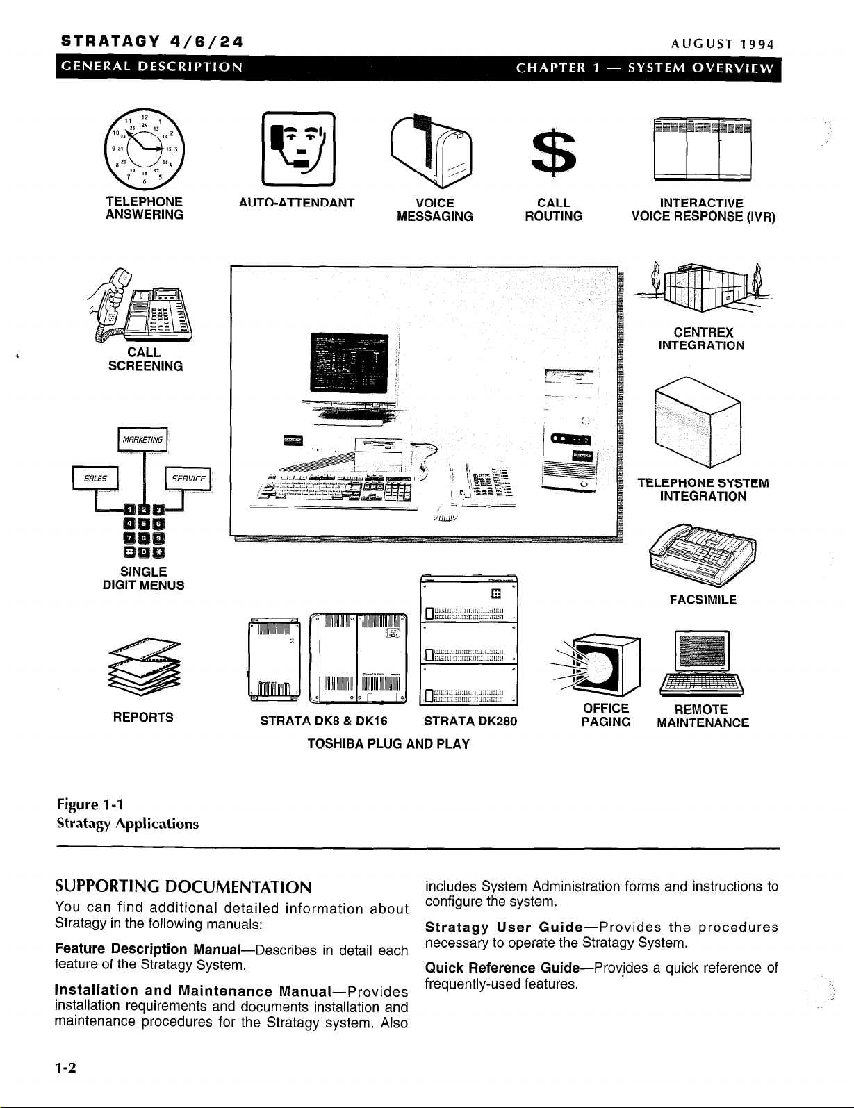
The Stratagy system is a multi-application voice
processing system, which is tailor-made for small- to
large-sized businesses. It has been designed to be
flexible and easy to use, while offering a full range of
features. (Refer to Figure l-1 .)
The Stratagy system easily integrates with most
telephone systems, providing call coverage and routing
for your entire organization. Stratagy also provides
enhanced integration with Toshiba telephone systems.
Chapter 4 includes general information on all Stratagy
features and integration capabilities with telephone
systems.
Stratagy provides basic applications such as Automated
Attendant to answer incoming calls, Call Routing to direct
calls, Telephone Answering to take messages when an
individual is unavailable or busy, and Voice Messaging to
create, send, receive, forward, and save voice
messages.
Additionally, Stratagy’s Token Programming Language
provides the flexibility to design custom individual
features and custom applications such as Fax
Integration, Interactive Voice Response, and more.
Stratagy is a turn-key voice processing system that runs
on a personal computer (PC) based platform. All service,
including installation and maintenance, is performed by
an authorized Toshiba dealer.
STRATAGY 6
The Stratagy 6, can be configured with 2,-4 or 6 ports,
with six hours of message capacity. It consists of a 486
computer with 2MB of RAM. The Stratagy 6 integrates
with most telephone systems. It does not have a monitor
or keyboard; it requires a lap-top computer for local and
remote access. An optional external 2400 baud modem
is available for remote maintenance.
STRATACY 24
The Stratagy 24, can be configured up to 24 ports, with a
storage capacity of 6, 20 or 33 hours. It consists of a 486
computer with 4MB of RAM. The Stratagy 24 integrates
with most telephone systems. It comes with a monitor
and keyboard for local access. An optional external 2400
baud modem is available for remote maintenance, which
also requires a lap-top computer. It has full fax
capabilities
SYSTEM TECHNOLOGY
The Stratagy system uses the following technology:
PC-based Architecture: The Stratagy system uses
standard PC-based architecture to form the basis of its
design. It uses a half and full length slot, PC bus form
factor motherboard. From two to four MB of RAM are
included, depending upon the configuration. DOS,
Stratagy’s operating system, and the Stratagy customer’s
configuration information, greetings and messages
(database) are’stored on an internal hard drive.
Microprocessor: A 486SX, 25 MHz CPU is the
microprocessor for all Stratagy systems.
Voice Board: Stratagy uses a PC-based voice board to
convert, compress and store analog voice signals on the
internal hard disk drive.
SYSTEM CAPACITIES
Stratagy can be configured in various ways using three
different platforms. The Stratagy 4 and Stratagy 6 are
designed for small- to medium-sized businesses, and the
Stratagy 24 is designed for larger businesses.
STRATAGY 4
The Stratagy 4 can be configured with 2 or 4 ports, with
six hours of message capacity. It consists of a 486
computer with 2MB of RAM. The Stratagy 4 integrates
with the Strata DK8 and DK16 telephone systems only. It
does not have a monitor or keyboard; it requires a lap-top
computer for local and remote access. An optional
external 2400 baud modem is available for remote
maintenance.
POWER REQUIREMENTS
The Stratagy system has an input power source which
can be switched to 110 VAC or 220 VAC at 50-60 Hz.
MAINTENANCE
Stratagy systems are easy to maintain by an authorized
Toshiba dealer. Additionally, procedures for backing up,
restoring and maintaining the system software and/or
database are efficient and easy to perform.
l-1
STRATAGY 4/6/24
AUGUST
1994
TELEPHONE
ANSWERING
CALL
SCREENING
SINGLE
DIGIT MENUS
AUTO-ATTENDANT VOICE CALL
MESSAGING
ROUTING
INTERACTIVE
VOICE RESPONSE (IVR)
CENTREX
INTEGRATION
TELEPHONE SYSTEM
INTEGRATION
FACSIMILE
---- _
_--- ,..--
/-
s
REPORTS
Figure l-1
Stratagy Applications
SUPPORTING DOCUMENTATION
You can find additional detailed information about
Stratagy in the following manuals:
Feature Description Manual-Describes in detail each
feature of the Stratagy System.
Installation and Maintenance Manual-Provides
installation requirements and documents installation and
maintenance procedures for the Stratagy system. Also
STRATA DK8 & DK16 STRATA DK280
TOSHIBA PLUG AND PLAY
PAGING
includes System Administration forms and instructions to
configure the system.
Stratagy User Guide- Provides the procedures
necessary to operate the Stratagy System.
Quick Reference Guide-Provjdes a quick reference of
frequently-used features.
REMOTE
MAINTENANCE
1-2
STRATAGY 4/6/24
AUGUST 1994
CHAPTER 2
SYSTEM ARCHITECTURE
This sections describes the main components of the
Stratagy System. It provides general descriptions of the
following:
n System Hardware
n System Software
n Call Processing Software
n System Administration
,
HARDWARE
The hardware for the Stratagy system varies depending
upon the configuration. All telephone system connectors
and wiring are customer-supplied.
STRATAGY 4
Hardware: The Stratagy 4 consists of a standard DOS-
compatible 486 PC housed in a mini tower. The PC
comes equipped with 2 MB of RAM, a 3.5” disk drive,
and a hard disk drive, allowing up to 6 hours of
message storage. It supports 2 or 4 ports that
connect to the telephone system. There is no
keyboard or monitor. An optional 2400 baud external
modem is available for remote operation. Because it
uses the same hardware, the Stratagy 4 can be
easily upgraded to a Stratagy 6.
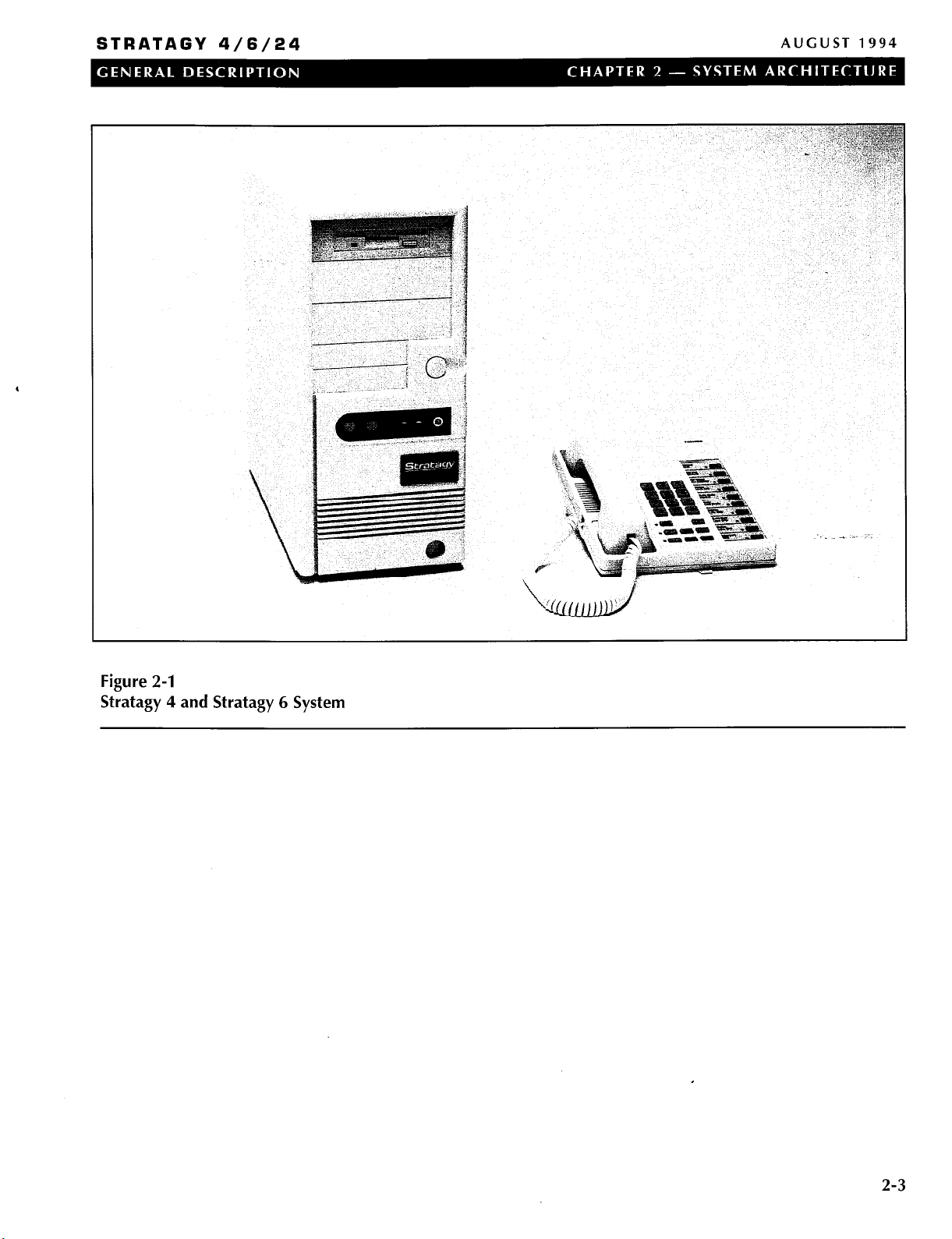
Refer to Figure 2-1 for an illustration of the Stratagy 4
system.
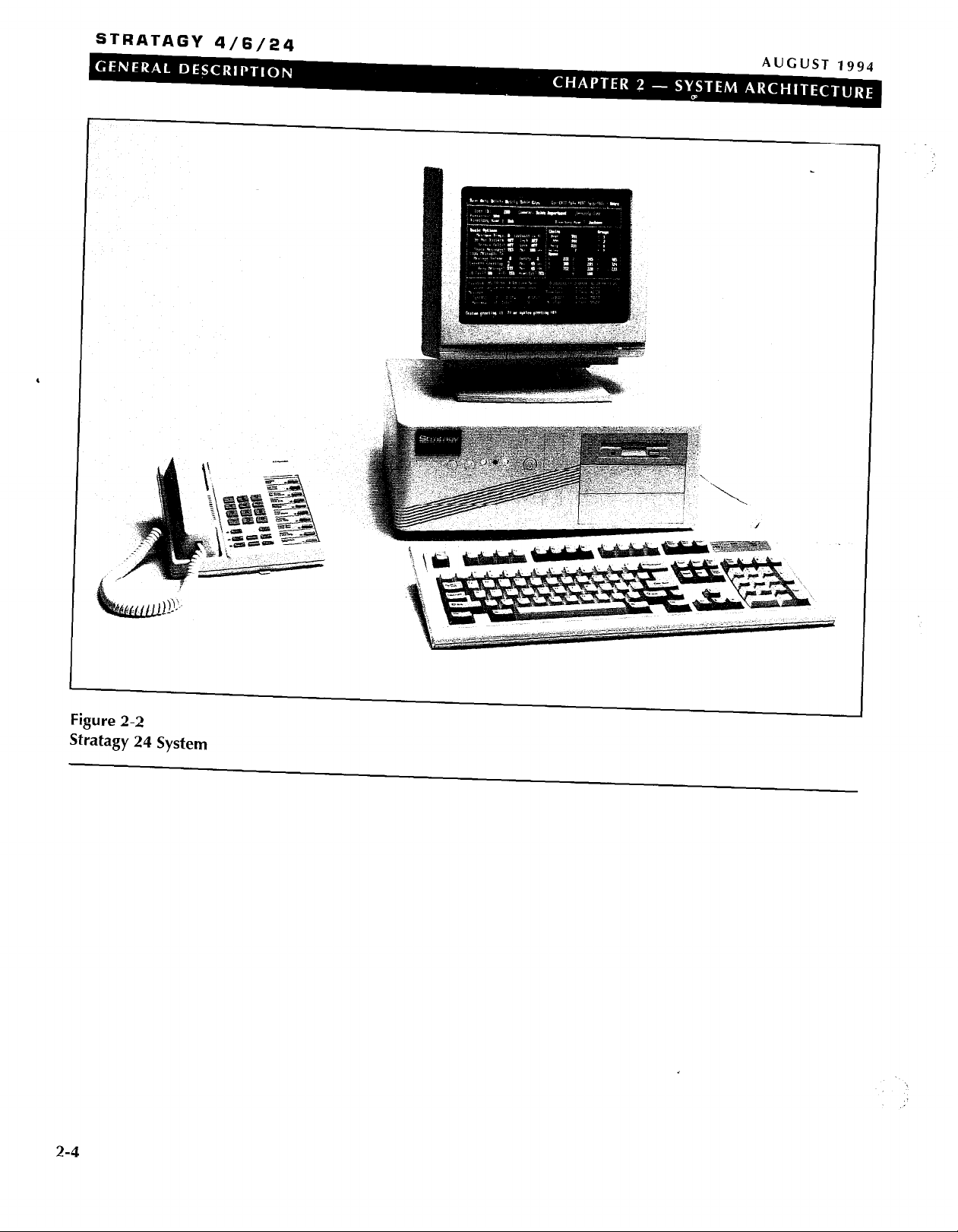
Monitor and Keyboard: The Stratagy 24 comes
equipped with a monochrome monitor used to
display Stratagy systems data. The accompanying
keyboard allows the System Administrator to input
commands and other information into the Stratagy
system.
Refer to Figure 2-2 for an illustration of the Stratagy 24
system.
INTERNAL COMPONENTS
The following provides a brief description of Stratagy’s
internal components.
MotherBoard: A 486SX, 25 MHz motherboard is
standard in all configurations of the Stratagy system.
Voice board: A voice board is used to convert, compress
and store analog voice signals on the internal hard
drive. The telephone system must be physically
connected to each voice board using the boards RJ-
14 type connectors. A voice board has one or two
connectors, and each connector supports two ports.
Power Supply: The power supply is a standard PC type
power supply, requiring a 110 VAC or 220 VAC input.
Hard Disk Drive: The Stratagy 4 and Stratagy 6 come
equipped with a 6 hour hard disk drive. The Stratagy
24 is equipped with either a 6, 20, or 33 hour hard
disk drive.
Floppy Disk Drive: The Stratagy system is equipped
with a 3.5” floppy disk drive.
STRATAGY 6
Hardware: The Stratagy 6 consists of a standard DOS-
compatible 486 PC housed in a mini tower. The PC
comes equipped with 2 MB of RAM, a 3.5” disk drive,
and a hard disk drive, allowing 6 hours of message
storage. It supports 2, 4, or 6 ports that connect to
the telephone system. There is no keyboard or
monitor. An optional 2400 baud external modem is
available for remote operation.
Refer to Figure 2-1 for an illustration of the Stratagy 6
system.
STRATAGY 24
Hardware: The Stratagy 24 consists of a standard DOS-
compatible desktop 486 PC. The PC comes
equipped with 4 MB of RAM, a 3.5” disk drive, a
choice of 3 different hard disk drives allowing 6, 20 or
33 hours of storage, and expansion slots for up to 24
ports that connect to the telephone system. An
optional 2400 baud external modem is available for
remote operation.
SOFTWARE
The Stratagy system’s flexibility is largely a result of its
software. The following provides a brief overview of the
Stratagy system software.
Operating System: Controls all real-time voice
processing functions through the use of simple
administrative menus as well as diagnostics, system
activity, and collection and reporting of data.
Installation Program: Used to create the database for
telephone system and specific customer information.
It is used when installing a new Stratagy system. A
SETUP Utility is also used during the installation
process for system configuration. Routine additions,
changes, and deletions of information are done
through this program.
Installation and Il/laintenance A&nua/ for more detail.
Diagnostic Programs: On-line diagnostic tests run
continuously to detect and report any errors in
operation. The tests run in the background and don’t
interfere with normal system operation. Other
Refer to the Stratagy
I
2-1
STRATAGY 4/6/24
AUGUST 1994
diagnostic tests may be run upon demand, either
from a directly-connected or remote terminal. Refer
to the Stratagy Installation and Maintenance Manual
for more detail.
CALL PROCESSING CONTROL
Call processing in Stratagy involves mailboxes (User
IDS), a Token Programming Language, and a series of
administrative menus.
MAILBOXES
Mailboxes, also called User IDS, are an important part of
the Stratagy system. Mailboxes, which are set up by the
System Administrator, determine what a caller hears and
call processing of Stratagy. For example, the initial
company greeting is defined by a mailbox. What a caller
hears is simply what you have recorded as the greeting
for this mailbox.
All of Stratagy’s mailboxes are uniquely numbered from 0
- 99,999,999. When a caller enters an extension, the
Stratagy system always accesses the same mailbox.
Thus, you cannot have two mailboxes with the same
number.
Mailboxes can be set up to fall into one of three general
categories:
User Mailbox - A typical mailbox is configured to
record messages from callers. A user periodically checks
the mailbox for messages, or a variety of automatic
notification methods may be employed. There is
generally one user for each mailbox, although several
mailboxes may share a single extension when the users
share a single phone line.
TOKEN PROGRAMMING LANGUAGE
Stratagy’s Token Programming Language allows
expansion of the standard capabilities of the Stratagy
System by using a series of tokens that tell the system
what actions to perform. Using this token language
allows Stratagy to perform the advanced applications
described in Chapter 3 of this General Description, and
more.
Tokens are used as field values in the administrative
menus. To program these fields, the installer or the
System Administrator enters a series of Programming
Language tokens which instruct Stratagy what actions to
perform.
ADMINISTRATIVE MENUS
A series of Stratagy menus allow an installer or the
System Administrator to customize system configuration
options and individual User IDS. These menus, along
with the call processing control structures discussed
above, are what provide voice processing capabilities for
telephone users and multiple application solutions for
customers. Refer to the Stratagy installation and
Maintenance Manual for more detail on Administrative
Menus.
Information Mailbox - An information mailbox is one
which does not accept messages from callers. Instead,
its greeting is played to callers to provide them with
information such as the company’s hours of business, its
location, etc. No real user or phone extension
corresponds to this type of mailbox.
Control Mailbox - This type of mailbox allows the
Stratagy to provide control over the flow of a call.
Typically, it interacts with the caller in some way, then
directs the call to one or more additional mailboxes for
processing using the Token Programming Language.
2-2
STRATAGY 4/6/24
AUGUST 1994
Figure 2-1
Stratagy 4 and Stratagy 6 System
,
2-3
STRATAGY 4/6/24
,
Figure 2-2
Stratagy 24 System
L..
/
2-4
STRATAGY 4/6/24
AUGUST 1994
CHAPTER 3
SYSTEM DEFINITIONS AND
APPLICATIONS
This chapter contains a list of terms that are commonly
used when discussing the Stratagy system. The second
part of the chapter describes some basic and advanced
applications which can be created using Stratagy.
Chapter 4 includes a brief description of all Stratagy
features. Refer to the Strategy Feature Description
,
AYanualfor feature details.
SYSTEM DEFINITIONS
PBIUPhone System - The Stratagy system integrates
with most business telephone systems: Private Branch
Exchange (PBX), Centrex (usually used to refer to a
Central Office located exchange), and hybrid key
systems. For convenience, the terms “phone system” or
“PBX” refer to the telephone systems to which the
Stratagy system connects.
Integration
made via RS-232 data connections dependent upon
the PBX capabilities. Data is passed in both
directions: the PBX informs the auto attendant/voice
mail system about each incoming call, and the voice
mail system can send instructions to the PBX to turn
message waiting lights on or off, as appropriate.
User and User ID - The subscriber of a mailbox. May
also be called subscriber and mailbox user. The User ID
indicates the number (0 to 99,999,999) for that user.
Mailbox - Mailboxes are a central element of the
Stratagy system. Messages, greetings, and other
information are recorded, stored, and activated in a
mailbox. Each extension receiving messages is assigned
a mailbox. The mailbox number represents the digits a
caller enters, usually the same as the extension number.
Not all mailboxes have associated extensions. Some
don’t even receive messages such as company greeting
mailboxes, and information mailboxes.
Extensions - Extensions are telephones connected to
the telephone system.
configuration, extension is also used to mean the digits
that the system dials. These digits are usually an
extension number, but they may be any sequence that
can be dialed on the PBX. This includes speed dial
numbers or access digits, such as 9, used to access
outgoing lines for calls.
In the Stratagy system’s
Dual Integration
Normally, all of a Stratagy system’s ports will be
attached to a single telephone system. But it is
possible to configure both the Stratagy 6 and the
Stratagy 24 systems on a per-port basis to work with
two different telephone systems simultaneously.
Because the system can operate with different
telephone systems simultaneously, it is appropriate
for use in offices where, possibly, two different
companies, with two different phone systems, would
like to share the costs and benefits of a single
Stratagy system.
lnband Integration
Many telephone systems (PBXs) can be configured
to provide information to the Stratagy system about
an incoming call by preceding it with one or more
DTMF digits. These DTMF strings are known as
lnband Integration or lnband Signaling. The Stratagy
system can be configured to receive and interpret
these DTMF strings. With this information, the
Stratagy system may answer the call with a company
greeting, direct the call to begin recording a message
for a user who is unavailable, etc.
SMDI/RS-232 Integration
SMDI integration is available on both Stratagy 6 and
Stratagy 24 systems. SMDI is an industry standard
method of integrating a PBX with Voice Mail and
other peripheral systems. This interconnection is
Ports - The Stratagy system is connected to the phone
system as a series of DTMF tone dialing single-line
extensions (2500-type sets). The number of ports
configured determines the maximum number of calls the
Stratagy system can handle simultaneously.
Company Greetings - The Company Greeting is the
announcement callers hear after the Stratagy system
answers. A simple version is provided with the system:
“Thank you for calling. Please stay on the line for
assistance, or if you know the extension you wish to
reach, please dial it now.” A new company greeting can
be recorded to replace the default greeting. The greeting
can be specific to a group of ports.
Different greetings can also be used during different
times of day, different days of the week, and for holidays.
BASIC APPLICATIONS
This section describes the three basic Stratagy
applications: Automated Attendant, Telephone
Answering, and Voice Messaging.
AUTOMATED ATTENDANT
Stratagy’s automated attehdant application can be set up
to solve various answering requirements.
n Answer company lines: Callers don’t have to wait
when the operator is busy with other calls. Company
3-l
STRATAGY 4/6/24
AUGUST 1994
lines are answered quickly and courteously by
customized, automated greetings. If callers have a
rotary phone or don’t know the extension, they are
directed to an operator for assistance.
Be available all of the time: Callers can reach
n
Stratagy from any tone dialing telephone 24-hours-aday, 36.5days-a-year.
n
Provides callers with information: Callers may
receive recorded information such as the company
address, directions, product specifications or service
offerings and price information (also described as an
Audiotext feature). Menus make it easy for callers to
get the information they need.
n
4
Call Routing
Once a call is answered by the Stratagy system,
callers are routed to the extension, department, etc.,
they enter. If the extension number is not known, a
company directory may be used by dialing a name.
Stratagy can also be set up to direct rotary callers to a
live assistant. Additionally, if the line is unanswered or
busy, the call can be routed to another extension, to
the company operator or to a personal operator set up
for that particular mailbox (see Personal Operator in
the Advanced Applications section.)
Users can play, edit, replay and discard messages. They
can also forward messages to additional users and
perform many other voice messaging capabilities. In
addition, Stratagy 24 users can perform many of the
same features for fax messages as an option.
ADVANCED APPLICATIONS
The following is a partial list of the advanced applications
supported by Stratagy. Refer to Chapter 4 of this General
Description and the Stratagy Feature Description Manual
for more information.
CALL QUEUING
When Stratagy tries a user’s extension and finds that it is
busy, it may offer the caller the option of either leaving a
message or holding until the called extension becomes
available. If the caller opts to hold, then Stratagy may
play one or more pieces of “on-hold music” (which may,
in fact, not be music at all, but instead it could consist of
company, product, or other information). If more than one
caller chooses to hold for the same extension, then
Stratagy will queue the callers in the order that their calls
were received. In addition to the “on-hold music,” callers
will be informed of their position in this queue.
If all extensions are unavailable, a caller can hold or
hang up. If they hold, they may be placed in a queue.
They are then periodically told of their position in the
queue and can be offered options to hold for the next
available assistant, leave a message or dial another
extension.
If a fax tone is detected, Stratagy, can automatically
transfer to a fax machine connected to a telephone
system extension.
TELEPHONE ANSWERING
Stratagy offers comprehensive message taking
capabilities which provide telephone answering when an
individual is busy or unavailable to answer the telephone.
Up to seven greetings per mailbox may be recorded and
scheduled to play at various times of the day. This
ensures coverage 24-hours-a-day, seven-days-a-week.
When extensions are busy or don’t answer, Stratagy
returns to the caller. Depending on how the mailbox is
configured, the system states that the extension is busy
or that the extension or person doesn’t answer. The
caller is offered the choices of leaving a private message,
calling another extension, or reaching assistance.
VOICE MESSAGING
Stratagy voice messaging features allow users to create,
send, receive and save voice messages. Users can
access their messages from any tone dialing phone.
FAX MESSAGING
A Stratagy 24 system may be optionally configured with
one or two external fax modems. These modems may be
used for a variety of purposes, including Fax Messaging.
With Fax Messaging, the system accepts a fax document
in place of a voice message. Just as with the voice
recording, the fax is “recorded” and stored in the
recipient’s mailbox. When the user subsequently picks up
messages, messages containing faxes will be identified
to the user. If the user is calling from a fax machine (or
other device capable of receiving a fax), then the user
may request that the fax be transmitted (printed) on the
same phone connection. Alternatively, the user may
direct the Stratagy system to transmit the fax to another
phone number with a separate phone call.
FAX ON DEMAND/FAXBACK
A Stratagy 24 system may optionally be configured with
one or two fax modems. One use which can be made of
these modems is to provide fax documents to callers. By
using features similar to Audiotext as described in
Chapter 4 of this General Description, the caller may
select which fax document(s) are to be transmitted. The
transmission may be done over the same phone call
(“single-call”), or the Stratagy system may queue the fax
for later transmission (a “two call” arrangement, which
may make better use of a single fax modem). Depending
on how the system is programmed, multiple fax
documents may be transmitted in a single fax phone call.
3-2
STRATAGY 4/6/24
AUGUST 1994
FAX TONE DETECTION
The Stratagy Automated Attendant listens for incoming
fax tone when answering incoming lines. If fax tone is
detected Stratagy will transfer the fax call to the
destination extension designated by the User ID of the
connected fax machine.
INTERACTIVE VOICE RESPONSE (IVR)
The Stratagy 6 and Stratagy 24 systems provide a
number of powerful features which allow it to be used for
Interactive Voice Response (IVR) applications, in addition
to Auto Attendant and Voice Messaging. Programming
tokens exist which allow the system to prompt the user
for input (using a custom prompt), wait for the user to
enter a DTMF response, which will be stored into a
variable, and then use that information to access a
database to formulate a response. Databases may be on
the hard disk of the Stratagy system, accessed remotely
over a network, or accessed through the serial ports of
the Stratagy system, possibly connecting to a mainframe
or other data server. Queries can be constructed in a
free-form fashion, by using data in variables that is
entered by the caller.
Once a response has been determined from the
database, the Stratagy system may be programmed to
play this data back to the caller in a number of different
ways: as a date, time, monetary value (in dollars and
cents), or simply as a number. The value may be
combined with other custom-recorded prompts, so that
the system could, for example, respond to a caller with
the message “Your order for 6 items will be shipped on
July 17, 1994.” The number six and the date in this
example would be provided by the database, while the
phrases “Your order for” and “items will be shipped on”
would be recordings that the System Administrator would
make.
PERSONAL OPERATOR
The Stratagy system lets users specify a personal
operator extension to provide live, personal call coverage
when they are unavailable. If desired, callers can be
automatically transferred to this extension, or can have
the option of leaving a private message or being
transferred to company operator assistance.
TOKEN PROGRAMMING
An important aspect of the Stratagy system is the Token
Programming Language feature. While the Stratagy
system allows easy configuration of User IDS for
standard applications (Automated Attendant, Telephone
Answering, Voice Messaging, dialing a standard
extension, etc.), more sophisticated applications can be
developed using the same concepts by making use of
additional programming tokens. Besides the conventional
DTMF digits, Stratagy supports over forty additional
programming tokens. These tokens can perform
functions as simple as a hook flash, and as complicated
as sending a fax document in the background. But the
real power of the Token Programming Language is that
the tokens and the User IDS can be combined innew and
sophisticated ways to provide application solutions.
REPORTING
The System Administrator may generate an almost
unlimited number of different reports of system activity
and programming. Reports can contain columns
representing each of the fields of the User screen, and
they can cover either all or a subset of User IDS in the
system.
MULTIPLE SYSTEM LANGUAGES
The Stratagy system can be configured with any of a
number of different audio prompt files. The standard file
provides prompts in American English. The default
prompt file to use when a call first comes in can be
configured, and with appropriate system programming,
the caller can select a preferred language by entering
DTMF digits. Thus, Stratagy can be communicating in
different languages on different ports simultaneously.
Contact Product Marketing for the availability of other
languages.
3-3
STRATAGY 4/6/24
AUGUST 1994
CHAPTER 4
FEATURES
AUTOMATED DIRECTORY
The Stratagy Automated Directory allows a caller to
enter DTMF digits corresponding to the first few
letters of a user’s first or last name. Stratagy will then
play back the recorded spoken name and extension
of each User ID that matches the entered digits.
OVERVIEW
This section presents an overview of all features that are
available on Stratagy systems. All features are
categorized as System, Administration, or User features.
Some features apply to more than one category. See
Table 4-1 for an alphabetical list of these features. Some
features are not available on all Stratagy systems, see
,
Table 4-2 for a list of these features.
In addition, Stratagy 24 systems support four out of five
serial communication port (RS-232) options:
n
Fax Modem 1
n
Fax Modem 2
n
Remote Maintenance
q
IVR Host Connectivity
n
SMDI Integration
A
maximum of up to 4 of these options may be
configured for each Stratagy 24 system.
SYSTEM FEATURES
AUTOMATIC GAIN CONTROL
While recording a message from a caller or user,
Stratagy can perform Automatic Gain Control (AGC).
AGC helps to compensate for variations in voice
volume, telephone handsets, and other factors which
can cause messages to be recorded at low or
varying volumes. A message recorded using AGC
will be played back at a consistent, standard volume
level. This means that the user playing back
messages will not have to constantly adjust the
playback volume.
CALL QUEUING
When Stratagy tries a user’s extension and finds that
it is busy, it may offer the caller the option of either
leaving a message or holding until the called
extension becomes available. If the caller opts to
hold, then Stratagy may play one or more pieces of
“on-hold music” (which may, in fact, not be music at
all, but instead it could consist of company, product,
or other information). If more than one caller chooses
to hold for the same extension, then Stratagy will
queue the callers in the order that their calls were
received. In addition to the “on-hold music,” callers
will be informed of their position in this queue.
AUDIOTEXT
Allows a caller to retrieve audio information from the
Stratagy system. To obtain this information, the caller
merely enters DTMF digits, as directed by audio
prompts, and the appropriate information is then
played. This information could consist of general
information about the company, such as its address,
phone number, fax number, etc., or it could include
specific product descriptions or other information that
may be of interest to callers.
AUTOMATED ATTENDANT
The Stratagy system answers incoming lines and
allows callers to route their own calls. The caller
merely enters the User ID of the desired party. If that
User ID is recognized by the system, then the call
will be handled according to the configuration of that
User ID. This configuration may direct the Stratagy
system to dial an extension and, possibly after
performing Call Screening, pass the call on to the
user. If the user is in Do Not Disturb mode, then
Stratagy may play a prerecorded greeting and record
a message
from the caller.
CALL TRANSFER
The Stratagy Automated Attendant call routing
capability provides for a supervised or blind and
other types of call transfers to the destination
extension in the telephone system. All Stratagy
system call transfers are controlled by User IDS and
the extension field. Entering just the destination
extension into the extension field will cause a
supervised call transfer. Other call transfer types are
implemented with Tokens.
CALLER CONFIRMATION PRIOR TO
TRANSFERRI NC
When a caller stays on the line and does not enter
any DTMF digits, the Stratagy system assumes that
the caller is using a rotary phone. Therefore, the call
will be transferred to the operator for live assistance.
It is also possible that the caller has hung up, but for
some reason the telephone system has not detected
the hangup. Therefore; Stratagy can be configured to
ask the caller to confirm orally that someone is still
on the line before transferring to the operator.
Stratagy may be configured to hang up if there is no
response.
4-l
STRATAGY 4/6/24
AUGUST 1994
DISK REDUNDANCY
A Stratagy 24 system may be optionally configured
with two hard disks, rather than the standard single
hard disk. Under special software control, the
contents of the second hard disk will be an exact
duplicate of the first hard disk. This duplication is
performed in real time as changes are made to the
primary hard disk (recordings are made, settings
changed, messages deleted, etc.). Should the
primary hard disk develop a bad sector, the
secondary hard disk is then automatically used.
DUAL INTEGRATION
Normally, all of a Stratagy system’s ports will be
attached to a single telephone system. But it is
possible to configure both the Stratagy 6 and the
Stratagy 24 systems on a per-port basis to work with
two different telephone systems simultaneously (two
systems with lnband Integration or one system with
lnband Integration and one system with SMDI/RS232
Integration). Because the system can operate with
different telephone systems simultaneously, it is
appropriate for use in offices where, possibly, two
different companies, with two different phone
systems, would like to share the costs and benefits
of a single Stratagy system.
FAX MESSAGING
A Stratagy 24 system may be optionally configured
with one or two external fax modems. These
modems may be used for a variety of purposes,
including Fax Messaging. With Fax Messaging, the
system accepts a fax document in place of a voice
message. Just as with the voice recording, the fax is
“recorded” and stored in the recipient’s mailbox.
When the user subsequently picks up messages,
messages containing faxs will be identified to the
user. If the user is calling from a fax machine (or
other device capable of receiving a fax), then the
user may request that the fax be transmitted (printed)
on the same phone connection. Alternatively, the
user may direct the Stratagy system to transmit the
fax to another phone number with a separate phone
call.
FAX ON DEMAND/FAXBACK
A Stratagy 24 system may optionally be configured
with one or two fax modems. One use which can be
made of these modems is to provide fax documents
to callers. By using features similar to Audiotext, the
caller may select which fax document(s) are to be
transmitted. The transmission may be done over the
same phone call (“single-call”), or the Stratagy
system may queue the fax for later transmission (a
“two call” arrangement, which may make better use
of a single fax modem). Depending on how the
system is programmed, multiple fax documents may
be transmitted in a single fax phone call.
FAX TONE DETECTION
The Stratagy Automated Attendant listens for
incoming fax tone when answering incoming lines. If
fax tone is detected, Stratagy will transfer the fax call
to the destination extension designated by the User
ID of the connected fax machine.
GREETING RESTART
After a caller has left a voice message for a User ID,
the call may either be transferred back to the initial
“company” greeting User ID or the system may say
“Thank you for calling, Good-bye” and disconnect.
Callers often appreciate the ability to return to the
User’s Main Menu so that they can leave a message
for another system user.
INBAND INTEGRATION
Many telephone systems (PBXs) can be configured
to provide information to the Stratagy system about
an incoming call by preceding it with one or more
DTMF digits. These DTMF strings are known as
lnband Integration or lnband Signaling. The Stratagy
system can be configured to receive and interpret
these DTMF strings. With this information, the
Stratagy system may answer the call with a company
greeting, direct the call to begin recording a message
for a user who is unavailable, etc. Data is passed in
both directions: the PBX informs the auto
attendant/voice mail system about each incoming
call, and the voice mail system can send instructions
to the PBX to turn message waiting lights on or off,
as appropriate.
INTERACTIVE VOICE RESPONSE (IVR)
The Stratagy 6 and Stratagy 24 systems provide a
number of powerful features which allow them to be
used for Interactive Voice Response (IVR)
applications, in addition to Auto Attendant and Voice
Messaging. There are programming tokens which
allow the system to prompt the user for input (using a
custom prompt), wait for the user to enter a DTMF
response, which will be stored into a variable, and
then use that information to access a database to
formulate a response. Databases may be on the
hard disk of the Stratagy system, accessed remotely
over a network, or accessed through the serial ports
of the Stratagy system, possibly connecting to a
mainframe or other data server. Queries can be
constructed in a free-form fashion, by using data in
variables that is entered by the caller.
Once a response has been determined from the
database, the Stratagy system may be programmed
to play this data back to the caller in a number of
different ways: as a date, time, monetary value (in
dollars and cents), or simply as a number. The value
may be combined with other custom-recorded
>,,
1
”
4-2
STRATAGY 4/6/24
AUGUST 1994
prompts, so that the system could, for example,
respond to a caller with the message “Your order for
6 items will be shipped on July 17, 1994.” The
number six and the date in this example would be
provided by the database, while the phrases “Your
order for” and “items will be shipped on” would be
recordings that the System Administrator would
make.
MULTIPLE SYSTEM LANGUAGES
The Stratagy system can be configured with any of a
number of different audio prompt files. The standard
file provides prompts in American English. The
default prompt file to use when a call first comes in
can be configured, and with appropriate system
programming, the caller can select a preferred
language by entering DTMF digits. Thus, Stratagy
can be communicating in different languages on
different ports simultaneously.
Contact Product Marketing for the availability of other
languages.
PORT-SELECTABLE GREETINGS
The Stratagy system may be configured to begin
processing new calls by starting with a given User
ID. New callers will first hear the greeting recorded
for this User ID. Each different audio port in the
Stratagy system may be configured to begin
processing with a different port, and thus different
ports may hear different initial greetings, which may
have different menu options available, which may
follow different processing paths, etc., depending on
how the User IDS are programmed. This feature
might be used, for example, by two companies
sharing the same Stratagy system.
REMOTE ADMINISTRATION
An optional external 2400 baud modem is required
for this feature on all Stratagy systems. The remote
administrator has full screen access to the system,
protected by two different passwords, with every
system feature available. The remote administrator
may use this feature at any time simply by dialing
into the system from any PC running the Stratagy
remote access software and with an appropriate
modem.
SAFE MESSAGE PURGING
The Stratagy system may be configured to “purge”
messages some time after they have been heard.
This time period is a system configuration parameter
expressed in days. The default value for this
parameter is 0, meaning that no purging will ever be
performed. The purge parameter is system-wide.
Stratagy performs the purge on a per-User ID basis,
only when the user is logging out of the system.
When the user logs into the system, Stratagy
announces the number of messages-in the User ID
that are to be purged, if any. This gives the user
ample warning that the messages will be deleted
upon logout. Messages are never purged at any
other time. Messages that have not been heard are
never purged, no matter how old they are.
SMDI/RS-232 INTEGRATION
SMDI integration is available on both Stratagy 6 and
Stratagy 24 systems. SMDI is an industry standard
method of integrating a PBX with Voice Mail and
other peripheral systems. This interconnection is
made via RS-232 data connections dependent upon
the PBX capabilities. Data is passed in both
directions: the PBX informs the auto attendant/voice
mail system about each incoming call, and the voice
mail system can send instructions to the PBX to turn
message waiting lights on or off, as appropriate.
SYSTEM BACKUP
This feature allows customer configuration database
information, greetings, and messages to be backed-
up onto floppy diskettes. Database information,
greetings, and messages may be backed-up
individually or in various combinations. Stratagy will
estimate the number of floppy diskettes required for
the System Backup procedures.
TOKEN PROGRAMMING
An important aspect of the Stratagy system is the
Token Programming feature. While the Stratagy
system allows easy configuration of User IDS for
standard features (Audiotext, Automated Attendant,
Voice Messaging, dialing a standard extension, etc.),
more sophisticated applications can be developed
using the same concepts, by making use of
additional programming tokens. Besides the
conventional DTMF digits, Stratagy supports over
forty additional programming tokens. These tokens
can perform functions as simple as a hook flash, and
as complicated as sending a fax document in the
background. But the real power of the Token
Programming Language is that the tokens and the
User IDS can be combined in new and sophisticated
ways to provide application solutions.
TOSHIBA PLUG AND PLAY
Stratagy systems have been preconfigured for out of
box plug and play use with certain Toshiba telephone
systems: Stratagy 4 with Strata DK 8, Stratagy 6 with
Strata DK16, and Stratagy 24 with Strata DK 280 A.
The installer does not have to understand or program
inband integration strings, ringback patterns, or make
other system configuration changes. In addition the
above Strata DK default extension numbers are also
preprogrammed in Stratagy as the User ID and
4-3
STRATAGY 4/6/24
AUGUST 1994
extension numbers, plus default user parameters.
Complete integration with other Toshiba telephone
systems (without default User IDS and extension
mailbox installations) is available from a menu.
UNIVERSAL PORTS
Frequently, notification is performed by dialing out on
one of the Stratagy audio ports, perhaps to send a
page or light a message waiting light by transmitting
the correct sequence of DTMF codes. Stratagy
provides several methods of allocating audio ports
for the notification process. With the first method,
one or more ports are dedicated to perform out
dialing for notification. This method has the
‘
advantage that there can never be a collision
between dialing out to perform a notification and an
incoming call which happens to be routed to the
same port at the same time. With the second
method, all of the Stratagy ports are configured to
accept incoming calls, but Stratagy can also use any
one of them which is not currently in use to perform
an outdial. This method has a clear advantage over
the first, particularly for small systems with only a
limited total number of ports. However, it introduces
the possibility of a collision. The third method is
similar to the second, except that Stratagy is
restricted to choosing only one particular port to
perform notifications. Should that one port be busy,
then Stratagy will wait until it is free rather than use
one of the remaining ports.
VARIED SAMPLING RATES
The Stratagy system may be configured-to make
different types of recordings at different “sampling
rates.” In general, the higher the sampling rate, the
more accurate the digital recording of the incoming
sound will be, and thus, the better the reproduction.
However, using a high sampling rate means that
more disk space will be consumed for a given
recording. Because companies wish to present the
best possible “appearance” to their callers, and
because greetings usually represent only a small
fraction of the system’s disk space, Stratagy systems
are configured to record greetings at a higher
sampling rate (64K) than regular voice messages
(32K). However, the sampling rate for greetings and
for voice message recordings can be individually set
during system installation and configuration by the
System Administrator.
VOICE MESSACI NC
In addition to the Automated Attendant feature, each
Stratagy system includes Voice Messaging. Each
User ID may be configured to store messages
individually. Voice Messaging functions may be
controlled by the System Administrator or the
individual user. See both Administration and User
Features for details.
UNLIMITED USER IDS
The Stratagy system provides User IDS of up to eight
digits, or 100 million different possible User IDS. User
IDS may be prefixes of other User IDS. That is, both
“111” and “1111” could be separate User IDS, and
both could be used by the system. Thus, no User IDS
are ever precluded. Stratagy uses a very efficient
method of accessing its database, so that system
response is not diminished when the database
contains a very large number of User IDS. No matter
how large a Stratagy system might grow to be, it
likely will never run out of available User IDS.
4-4
STRATAGY 4/6/24
AUGUST 1994
ADMINISTRATION FEATURES
IMPORTANT NOTE:
Stratagy 4 and Stratagy 6 systems require a
laptop computer with Stratagy remote software
installed to perform all Administration Features
locally or remotely (using an optional external
modem). The Stratagy 24 system may perform
all Administration Features in the same manner
as above or use the keyboard and monitor
supplied with the system. Refer to the Stratagy
Installation and Maintenance manual for details.
AUTOMATIC MESSAGE COPY
Each User ID “A” can be configured to place a copy
of any message received into a separate User ID
“B’s” queue of messages. User ID “A” will retain a
copy of each message. Messages sent directly to “B”
remain unaffected.
AUTOMATIC MESSAGE COPY WITH DELETE
This feature is very similar to Automatic Message
Copy. When activated, a User ID “A” is configured so
that any messages received will be copied to User ID
“B.” Furthermore, “A” is configured not to store
messages at all. This means that the copy of each
message sent to “B” is in reality the only copy of the
message in the system. Messages sent directly to
“B” would not be affected by this change, nor would
any messages already stored in “A.”
CHAINING
Stratagy’s chaining feature allows the-flow of control
during call processing to be directed from one User
ID to another, based on the results of dialing the
Extension field (if the User ID is not configured in Do
Not Disturb mode). The System Administrator may
define each of the three possible chaining conditions:
Busy, Ring No Answer (RNA), or Done. Combined
with Stratagy’s Token Programming Language, this
feature allows sophisticated call processing and IVR
applications to be created.
COPY RANGE
The Copy Range feature allows the System
Administrator to copy one existing User ID to create
a number of new User IDS, each within a defined
range of ID numbers.
DIRECTORY CONTROL
Each User ID may have Automated Directory names
entered by the System Administrator. Some users
may not wish to be listed in the Automated Directory.
Furthermore, some User IDS are used for special
purposes, and they should not appear in the
directory listings. Such User IDS would include “back
door” access numbers, User IDS used purely for
Stratagy programming, etc. The Automated Directory
allows callers to determine the correct extension for
someone by entering the DTMF digits which
correspond to the first few letters of the name.
AUTOMATIC MESSAGE DATE/TIME CONTROL
The System Administrator may configure each User
ID or group of User ID’s to automatically play the
date and time of each message before playing the
“body” (contents) of the message.
BUSY GREETING LENGTH CONTROL
The System Administrator may specify each User ID
maximum length of time in seconds for the custom
busy greeting which the user may record. This
feature may be used to limit the total time (and thus,
system disk space) which can be used for busy
greetings. Setting this field to zero prevents the user
from recording or changing a custom busy greeting.
CALLED IDENTIFICATION
Allows one person to answer for both “Sales” and
“Service” calls. The person who answers the call will
know how to greet each caller, since they will hear
“Sales” or “Service” before being connected to the
caller. Message Pooling could also be used in this
case, since this person would presumably like all
messages left after hours to be stored in a single
User ID, rather than have to check multiple User IDS
for messages. The System Administrator sets this
feature on a per User ID basis.
DISK SPACE NOTIFICATION
The Stratagy system can be configured to send an
automatic notification whenever system disk space
falls below a defined threshold. During system
installation and configuration, the System
Administrator defines the percentage of disk space
remaining below which the disk notification should be
activated. Under normal conditions, the system is
checked automatically once per hour to determine
the remaining disk space storage.
GREETING LENGTH CONTROL
The System Administrator may determine the
maximum recording time, in seconds, for the seven
different greetings of each User ID. This feature may
be used to limit the total time (and thus, system disk
space) which can be allotted for user greetings.
Setting this field to zero prevents the user from
recording or changing the “current” user greeting.
GROUP PARTITIONS - CALL BLOCKING
Each User ID may belong to as many as four
different “groups.” The System Administrator defines
the group(s) to which a User ID belongs. When the
Stratagy system transfers a call to a new User ID, it
4-5
STRATAGY 4/6/24
AUGUST 1994
first determines if that User ID has any groups in
common with the current User ID. If it does, then the
transfer of processing to the new User ID will
proceed. Otherwise, Stratagy will switch to a default
User ID for processing based on the current system
port number, blocking or rerouting the call. Group
Partitions are most often used to control Guest User
IDS and Shared Tenant applications.
GUEST USERS LIMIT
Each user of the Stratagy system may potentially
create one or more
might be used by that person’s customers, friends,
clients, etc. They can be deleted by the same user
who created them or by the System Administrator.
The System Administrator can also limit the number
of Guest User IDS which a particular User ID is
allowed to create.
Guest
User IDS. These User IDS
MESSAGE LENGTH CONTROL
The System Administrator can set the maximum
Message Length in seconds of each incoming
message for a given User ID, or messages may be
unlimited in length. If a caller attempts to leave a
message longer than the maximum, the system will
stop recording and inform the caller that the
maximum message length has been reached.
MESSAGE NOTIFICATION
Stratagy allows each User ID to have up to ten
different programmable notification records. The
System Administrator programs the notification
records of each User ID with a specific notification
method such as lights, stutter dialtone, pagers, voice,
etc., for the times of the day and the days of the
week and the repeat count and interval for retrying
that notification. Each notification method is a flexible
dial string allowing the Stratagy system to be used
with almost any kind of PBX or notification method
including cascade notification.
MULTIPLE DIRECTORY NAMES
Each User ID can have associated with it up to two
different names. These names are entered into the
Stratagy system’s automatic directory by the System
Administrator. Each User (Extension) may have more
than one User ID to improve the Automated Directory
for commonly misspelled names. The Automated
Directory can allow callers to determine the correct
extension for someone by entering the DTMF digits
which correspond to the first few letters of either one
of the two (or more) different names. Thus, normally,
the two different directory names will be the first and
last names of the user associated with each User ID.
NAME AND EXTENSION CONTROL
Normally, a user may record a “spoken name”-a
recording of the user’s name and extension. The
System Administrator, however, can configure User
IDS on an individual basis so that a user cannot
record, or change the recorded name and extension.
If no name and extension has been recorded for a
User ID, then the Stratagy system will play “User
ID...” followed by the number of that User ID.
PROGRAMMABLE DIAL ACTIONS
The Stratagy system will attempt to dial the string
specified in the Extension field. This string may
consist simply of the extension number of the user, in
which case Stratagy will dial that extension and
continue processing based on the results of that call
if not in the Do Not Disturb mode. But the extension
field may actually contain many more “programming
tokens” which can have effects ranging from the
simple (such as performing a hook flash) to the
complex (accept an incoming fax for the current
user). These programming tokens can be combined
by the System Administrator in a desired way to
create an almost unlimited number of application
solutions.
REAL-TIME SCREEN INFORMATION
The Administrator’s Main Menu on each Stratagy 24
system shows, among other things, the activity on
each audio port, the activity of any connected fax
modems, the amount of free disk space, etc. The
Stratagy 24 system helps the System Administrator
better understand and manage the system as
changes occur. This information is instantly updated
as long as the Main Menu is displayed.
RELAY PAGING
Relay Paging streamlines Message Notification
permitting the caller to enter a phone number while
the user’s greeting is being played. The Stratagy
system still pages the user, but instead of displaying
the usual information, only the phone number
entered by the caller is displayed on the pager. The
System Administrator may enable this feature
individually for each User ID. This allows the user to
return the call much sooner by not calling into the
Stratagy system since no voice mail message is left.
REPORTS
The System Administrator may generate an almost
unlimited number of different reports of system
activity and programming. Reports can contain
columns representing each of the fields of the User
screen, and they can cover either all or
User IDS in the system.
a subset
of
4-6
STRATAGY 4/6/24
AUGUST 1994
RING DURATION
The System Administrator may define, on a per-user
ID
basis, how many rings of that user’s extension the
Stratagy system should wait before concluding that
the user is unavailable (Ring No Answer, or RNA).
Then the Stratagy system can send callers to voice
mail to leave a message. This value may also be
changed automatically via the Auto Scheduler, again
on a per-User ID basis.
SCREEN SAVER
Standard feature on Stratagy 24 systems. Video
monitors, such as those used as the console display
of the Stratagy 24 system, should not have the same
image displayed on them constantly. Such an image
can become “burned in” on the phosphor display, and
it will then be visible even when other information is
being displayed-the monitor is then permanently
damaged. To avoid burn-in, the Stratagy system can
be configured to blank the screen automatically after
a predetermined period of keyboard inactivity. As
soon as something is again typed on the keyboard,
however, the screen is instantly reactivated, and any
information which would have been on the screen is
made visible.
SHARED EXTENSIONS
This feature is typically used when more than one
person, each with a separate Stratagy User ID,
shares a single phone extension. If the call is
answered, the called name is announced. If not
answered, a private message may be recorded.
Stratagy announces ‘&This call is for...” followed by
the recorded name of the called User ID. The
System Administrator sets this feature on a per User
ID basis. In addition, the System Administrator may
also turn on the Call Screening feature to enhance
this feature.
SINGLE-DIGIT MENUS
Each User ID may define one or more single-digit
menu keys. If a caller enters one of these DTMF
digits while listening to the greeting for that User ID,
then Stratagy will immediately transfer processing to
the User ID associated with that menu item rather
than process the digit as part of another User ID
number. The System Administrator defines the
single-digit menu numbers for each User ID.
SCHEDULED AUDIOTEXT
The Stratagy Auto Scheduler can be used to
implement Audiotext with a combination of single-
digit menus and greeting recordings. The System
Administrator would record the greetings in each of
the applicable User Ids and configure the system to
change the Audiotext contents on an automatic,
scheduled basis.
SCHEDULED COMPANY GREETINGS
The System Administrator may program the
company greetings using the Stratagy Auto
Scheduler to make changes based on the time of
day or day of week. The changes can include the
current greeting number, extension, Do Not Disturb
setting, etc.
SYSTEM DISTRIBUTION LISTS
In addition to personal distribution lists, Stratagy
supports system-wide distribution lists. A user sends
a message to a system distribution list rather than a
personal distribution list by prepending a * to the list
number. The “list comment” for the selected system
list is played to confirm that the right list has been
chosen, just as with personal distribution lists. The
System Administrator creates the system Distribution
Lists using the same method as the personal lists,
but for the System Administrator User ID.
URGENT MESSAGE NOTIFICATION
The System Administrator programs the notification
type set to URGENT. When a message-marked
Urgent is received, then the Stratagy system first
checks if one or more notification records exist for
that User ID with notification type URGENT. If so,
then those records are activated, and otherwise, any
NORMAL notification records are used. Users might,
for example, want to be notified by pager only when
an Urgent message arrives.
USER OPTION LOCKS
Many user options can normally be changed by
users themselves by selecting the appropriate DTMF
commands over the telephone, such as toggling the
Do Not Disturb attribute, changing the current
greeting number, toggling Call Screening, etc. The
System Administrator can disallow a user from
changing each of these settings on an individual
basis.
VOICE FORMS
The Stratagy system can be configured to prompt a
caller with a series of questions. The voice
responses that the caller gives are then
concatenated and are stored as a single message in
the associated User ID. The Voice Forms feature is
activated by the System Administrator simply by
using the “Q” (Question and Answer) token when
programming the User ID. Each question is recorded
as a greeting, either in that User ID or in others. The
“Q” token specifies which greetings should be played
to callers and the order in which they should be
played.
,
4-7
STRATAGY 4/6/24
AUGUST 1994
USER FEATURES
BUSY GREETING
When a caller is directed to an extension which is
busy, Stratagy can play a recorded greeting specific
to this situation. The default is that the system will
play a standard system busy greeting that says “That
extension is busy, to hold press *, to try another
extension enter it now, to leave a message please
stay on the line,” but users may record their own
custom busy greetings that will be played instead.
CALL QUEUING
When Stratagy tries a user’s extension and finds that
it is busy, it may offer the caller the option of either
leaving a message or holding until the called
extension becomes available. If the caller opts to
hold, then Stratagy may play one or more pieces of
“on-hold music” (which may, in fact, not be music at
all, but instead it could consist of company, product,
or other information). If more than one caller chooses
to hold for the same extension, then Stratagy will
queue the callers in the order that their calls were
received. In addition to the “on-hold music,” callers
will be informed of their position in this queue.
CALL SCREENING
Each User ID may be configured for call screening.
Whenever a caller enters the User ID of the user with
call screening enabled, the system will request that
the caller say their name and company name.
Stratagy records this information, dials the extension
of the user, and announces that this caller is on the
line by playing the recording. The called user may
then enter DTMF digits to indicate that the call
should be accepted or rejected; rejected callers are
directed to leave a voice mail message for the user.
Also see Scheduled Call Screening.
CONTINUOUS MESSAGE DELETE
This feature is used in conjunction with the
Continuous Message Playback feature. It allows a
user to enter a DTMF command that will delete a
number of messages at once. The number of
messages that will be deleted is variable; it is the
maximum number of messages whose cumulative
length is less than a predetermined number of
minutes. For example, this feature may be used by
transcription services which are accustomed to
working from audio tape recordings rather than
directly from voice mail recordings.
CONTINUOUS MESSAGE PLAYBACK
This feature is used in conjunction with the
Continuous Message Delete feature. It allows a user
to enter a DTMF command which will play back a
number of messages at once, without stopping
between each message. The number of messages
that will be played is variable; it is the maximum
number of messages whose cumulative length is
less than a predetermined number of minutes. For
example, this feature may be used by transcription
services which are accustomed to working from
audio tape recordings rather than directly from voice
mail recordings.
DO NOT DISTURB
When a caller enters the number of a User ID,
Stratagy normally tries dialing the extension given in
that user’s Extension field to determine if the called
extension is available. When the Stratagy Do Not
Disturb feature is activated, however, Stratagy will
not dial the Extension field, but instead the call will
be processed as if the called extension is not
available (Ring No Answer), and the caller will be
offered the chance to leave a voice mail for the user
(provided that the User ID is configured to accept
messages).
FAX MESSAGE IMMEDIATE RETRIEVE
An optional feature on Stratagy 24 systems is to
attach one or two fax modems. These modems may
then be configured for a number of different
purposes, including accepting fax mail for users in
addition to voice mail. When a user has received a
message containing a fax, the message may be
retrieved in one of two ways: Fax Message
Immediate Retrieve and Fax Message Send
Retrieve. In the case of Immediate Retrieve, the user
calls into the Stratagy 24 system from a fax machine
with a handset (or other device capable of receiving
a fax where prompts can be heard and DTMF tones
transmitted). The user reviews the message
normally. When the fax message is played, the user
is prompted that the message contains a fax, and the
number of pages of the fax. If the user then chooses
the Immediate Retrieve option, the user is prompted
to press the Start key on the fax machine, and
Stratagy begins transmitting the fax over the
connection. When the fax has been transmitted, the
call is disconnected.
FAX MESSAGE SEND RETRIEVE
An optional feature on Stratagy 24 systems is to
attach one or two fax modems. These modems may
then be configured for a number of different
purposes, including accepting fax mail for users in
addition to voice mail. When a user has received a
message containing a fax, the message may be
retrieved in one of two ways: Fax Message
Immediate Retrieve and Fax Message Send
Retrieve. In the case of Fax Message Send Retrieve,
\
_,,
..
,,
-..-’
4-8
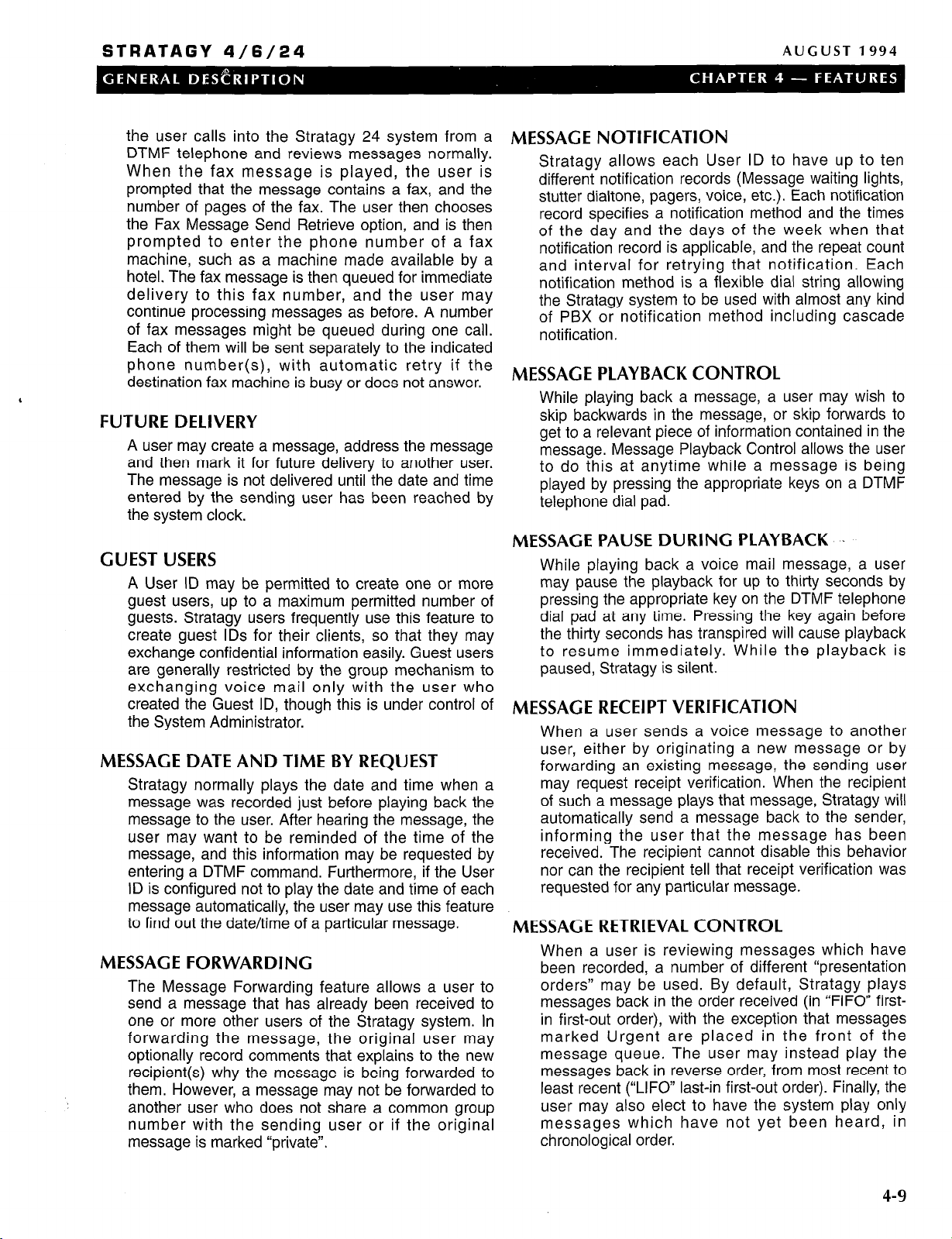
STRATAGY 4/6/24
AUGUST 1994
the user calls into the Stratagy 24 system from a
DTMF telephone and reviews messages normally.
When the fax message is played, the user is
prompted that the message contains a fax, and the
number of pages of the fax. The user then chooses
the Fax Message Send Retrieve option, and is then
prompted to enter the phone number of a fax
machine, such as a machine made available by a
hotel. The fax message is then queued for immediate
delivery to this fax number, and the user may
continue processing messages as before. A number
of fax messages might be queued during one call.
Each of them will be sent separately to the indicated
phone number(s), with automatic retry if the
destination fax machine is busy or does not answer.
FUTURE DELIVERY
A user may create a message, address the message
and then mark it for future delivery to another user.
The message is not delivered until the date and time
entered by the sending user has been reached by
the system clock.
GUEST USERS
A User ID may be permitted to create one or more
guest users, up to a maximum permitted number of
guests. Stratagy users frequently use this feature to
create guest IDS for their clients, so that they may
exchange confidential information easily. Guest users
are generally restricted by the group mechanism to
exchanging voice mail only with the user who
created the Guest ID, though this is under control of
the System Administrator.
MESSAGE DATE AND TIME BY REQUEST
Stratagy normally plays the date and time when a
message was recorded just before playing back the
message to the user. After hearing the message, the
user may want to be reminded of the time of the
message, and this information may be requested by
entering a DTMF command. Furthermore, if the User
ID is configured not to play the date and time of each
message automatically, the user may use this feature
to find out the date/time of a particular message.
MESSAGE FORWARDING
The Message Forwarding feature allows a user to
send a message that has already been received to
one or more other users of the Stratagy system. In
forwarding the message, the original user may
optionally record comments that explains to the new
recipient(s) why the message is being forwarded to
them. However, a message may not be forwarded to
another user who does not share a common group
number with the sending user or if the original
message is marked “private”.
MESSAGE NOTIFICATION
Stratagy allows each User ID to have up to ten
different notification records (Message waiting lights,
stutter dialtone, pagers, voice, etc.). Each notification
record specifies a notification method and the times
of the day and the days of the week when that
notification record is applicable, and the repeat count
and interval for retrying that notification. Each
notification method is a flexible dial string allowing
the Stratagy system to be used with almost any kind
of PBX or notification method including cascade
notification.
MESSAGE PLAYBACK CONTROL
While playing back a message, a user may wish to
skip backwards in the message, or skip forwards to
get to a relevant piece of information contained in the
message. Message Playback Control allows the user
to do this at anytime while a message is being
played by pressing the appropriate keys on a DTMF
telephone dial pad.
MESSAGE PAUSE DURING PLAYBACK ..
While playing back a voice mail message, a user
may pause the playback for up to thirty seconds by
pressing the appropriate key on the DTMF telephone
dial pad at any time. Pressing the key again before
the thirty seconds has transpired will cause playback
to resume immediately. While the playback is
paused, Stratagy is silent.
MESSAGE RECEIPT VERIFICATION
When a user sends a voice message to another
user, either by originating a new message or by
forwarding an existing message, the sending user
may request receipt verification. When the recipient
of such a message plays that message, Stratagy will
automatically send a message back to the sender,
informing the user that the message has been
received. The recipient cannot disable this behavior
nor can the recipient tell that receipt verification was
requested for any particular message.
MESSAGE RETRIEVAL CONTROL
When a user is reviewing messages which have
been recorded, a number of different “presentation
orders” may be used. By default, Stratagy plays
messages back in the order received (in “FIFO” first-
in first-out order), with the exception that messages
marked Urgent are placed in the front of the
message queue. The user may instead play the
messages back in reverse order, from most recent to
least recent (“LIFO” last-in first-out order). Finally, the
user may also elect to have the system play only
messages which have not yet been heard, in
chronological order.
4-9
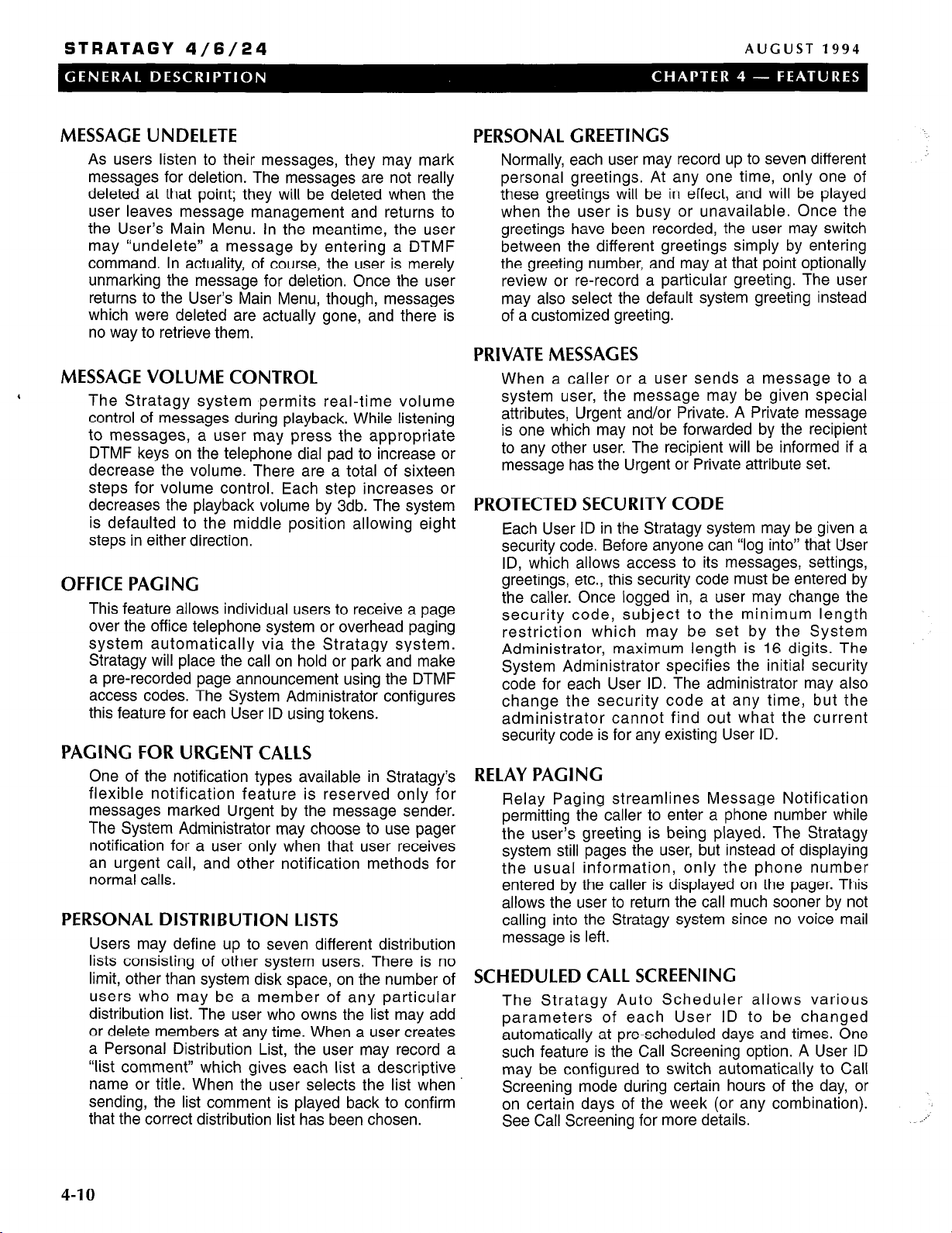
STRATAGY 4/6/24
AUGUST 1994
MESSAGE UNDELETE
As users listen to their messages, they may mark
messages for deletion. The messages are not really
deleted at that point; they will be deleted when the
user leaves message management and returns to
the User’s Main Menu. In the meantime, the user
may “undelete” a message by entering a DTMF
command. In actuality, of course, the user is merely
unmarking the message for deletion. Once the user
returns to the User’s Main Menu, though, messages
which were deleted are actually gone, and there is
no way to retrieve them.
MESSAGE VOLUME CONTROL
The Stratagy system permits real-time volume
control of messages during playback. While listening
to messages, a user may press the appropriate
DTMF keys on the telephone dial pad to increase or
decrease the volume. There are a total of sixteen
steps for volume control. Each step increases or
decreases the playback volume by 3db. The system
is defaulted to the middle position allowing eight
steps in either direction.
OFFICE PACING
This feature allows individual users to receive a page
over the office telephone system or overhead paging
system automatically via the Stratagy system.
Stratagy will place the call on hold or park and make
a pre-recorded page announcement using the DTMF
access codes. The System Administrator configures
this feature for each User ID using tokens.
PAGING FOR URGENT CALLS
One of the notification types available in Stratagy’s
flexible notification feature is reserved only for
messages marked Urgent by the message sender.
The System Administrator may choose to use pager
notification for a user only when that user receives
an urgent call, and other notification methods for
normal calls.
PERSONAL DISTRIBUTION LISTS
Users may define up to seven different distribution
lists consisting of other system users. There is no
limit, other than system disk space, on the number of
users who may be a member of any particular
distribution list. The user who owns the list may add
or delete members at any time. When a user creates
a Personal Distribution List, the user may record a
“list comment” which gives each list a descriptive
name or title. When the user selects the list when
sending, the list comment is played back to confirm
that the correct distribution list has been chosen.
PERSONAL GREETINGS
Normally, each user may record up to seven different
personal greetings. At any one time, only one of
these greetings will be in effect, and will be played
when the user is busy or unavailable. Once the
greetings have been recorded, the user may switch
between the different greetings simply by entering
the greeting number, and may at that point optionally
review or re-record a particular greeting. The user
may also select the default system greeting instead
of a customized greeting.
PRIVATE MESSAGES
When a caller or a user sends a message to a
system user, the message may be given special
attributes, Urgent and/or Private. A Private message
is one which may not be forwarded by the recipient
to any other user. The recipient will be informed if a
message has the Urgent or Private attribute set.
PROTECTED SECURITY CODE
Each User ID in the Stratagy system may be given a
security code. Before anyone can “log into” that User
ID, which allows access to its messages, settings,
greetings, etc., this security code must be entered by
the caller. Once logged in, a user may change the
security code, subject to the minimum length
restriction which may be set by the System
Administrator, maximum length is 16 digits. The
System Administrator specifies the initial security
code for each User ID. The administrator may also
change the security code at any time, but the
administrator cannot find out what the current
security code is for any existing User ID.
RELAY PAGING
Relay Paging streamlines Message Notification
permitting the caller to enter a phone number while
the user’s greeting is being played. The Stratagy
system still pages the user, but instead of displaying
the usual information, only the phone number
entered by the caller is displayed on the pager. This
allows the user to return the call much sooner by not
calling into the Stratagy system since no voice mail
message is left.
SCHEDULED CALL SCREENING
The Stratagy Auto Scheduler allows various
parameters of each User ID to be changed
automatically at pre-scheduled days and times. One
such feature is the Call Screening option. A User ID
may be configured to switch automatically to Call
Screening mode during certain hours of the day, or
on certain days of the week (or any combination).
See Call Screening for more details.
4-10

STRATAGY 4/6/24
SCHEDULED DO NOT DISTURB SINGLE-DIGIT MENUS
The Stratagy Auto Scheduler allows various
parameters of each User ID to be changed
automatically at pre-scheduled days and times. One
such feature is the Do Not Disturb option. A User ID
may be configured to turn this option on or off
automatically at pre-scheduled times and/or days of
the week. See Do Not Disturb for more details.
While a user’s greeting is being played, a caller may
enter a Single-Digit Menu that allows the caller to
select an option, such as Audiotext, a personal
assistant, call queuing or the operator, etc. When the
caller enters one of the defined single-digit menu
keys, the system will process the User ID associated
with that menu item. Each User ID may have an
individual Personal Single-Digit Menu.
SCHEDULED EXTENSIONS
The Stratagy Auto Scheduler permits several
attributes of a User ID to be changed on an
automatically scheduled basis. One of these
attributes is the Extension field. A User ID may be
configured to change the Extension field
automatically at a certain time and/or day. Two such
Auto Scheduler records could be used to toggle the
Extension field between two different values.
Automatically scheduled Extension changes might
be useful, for example, for a user who works from
two different locations on a regular basis. The
Stratagy system could be programmed to ring the
phone at the correct location automatically, without
the need for the user to enter anv call forwardina
information manually each time the-user moves to a
different location.
SCHEDULED GREETINGS
The Stratagy Auto Scheduler allows several options,
or attributes, of a User ID to be changed on a
regular, pre-scheduled basis. These attributes can be
set to change on certain days of the week, times of
day, or based on the date. The greeting number for
the User ID is one of these attributes which can be
changed automatically. See Personal Greetings for
more detail.
SCHEDULED MESSAGE NOTIFICATION
One of the many features of Stratagy’s flexible
message notification system is the ability to configure
the applicable time and day for each notification
record. Notifications can be set to occur only during
certain hours, on only certain days of the week, or
any combination thereof. See Message Notification
for more details.
SINGLE-DIGIT MESSAGE REPLY
If one Stratagy user sends voice mail to another
user, then the recipient can send a reply message to
the original sender without having to reenter the
sender’s User ID. While listening to messages, the
DTMF command to Send a Message also functions
as a Reply command by filling in the “from”
information in the current message as the “to”
information of the new message. If the recipient is
not replying, but instead is sending a brand new
message, then the user can simply enter that other
User ID, overwriting the default that was filled in
automatically.
URGENT MESSAGES
When a caller or a user sends a message to a
system user, the message may be given special
attributes, Urgent and/or Private. The recipient will be
informed if a message has the Urgent or Private
attribute set. Furthermore, Urgent messages have
two special attributes. First, when an Urgent
message is received by a User ID, it is placed at the
beginning of that User ID’s message queue. When
the messages are reviewed by the user, messages
marked Urgent are always played back first,
regardless of the message retrieval order selected by
the user. The second soecial feature of Uraent
messages is that there is an Urgent notification $pe.
This allows users to be notified differently for urgent
messages than they are when normal messages are
received. In fact, a user might have no notification
set up at all for normal messages, but might have
Pager Notification configured for urgent messages.
AUGUST 1994
.
SCHEDULED RING DURATION
The Stratagy Auto Scheduler allows several options,
or attributes, of a User ID to be changed on a
regular, pre-scheduled basis. These attributes can be
set to change on certain days of the week, times of
day, or based on the date. The ring duration for the
User ID is one of these attributes which can be
changed automatically. See Administration Features
- Ring Duration for more details.
4-l 1

STRATAGY 4/6/24
AUGUST 1994
4-12
Table 4-1
Stratagy Features ,
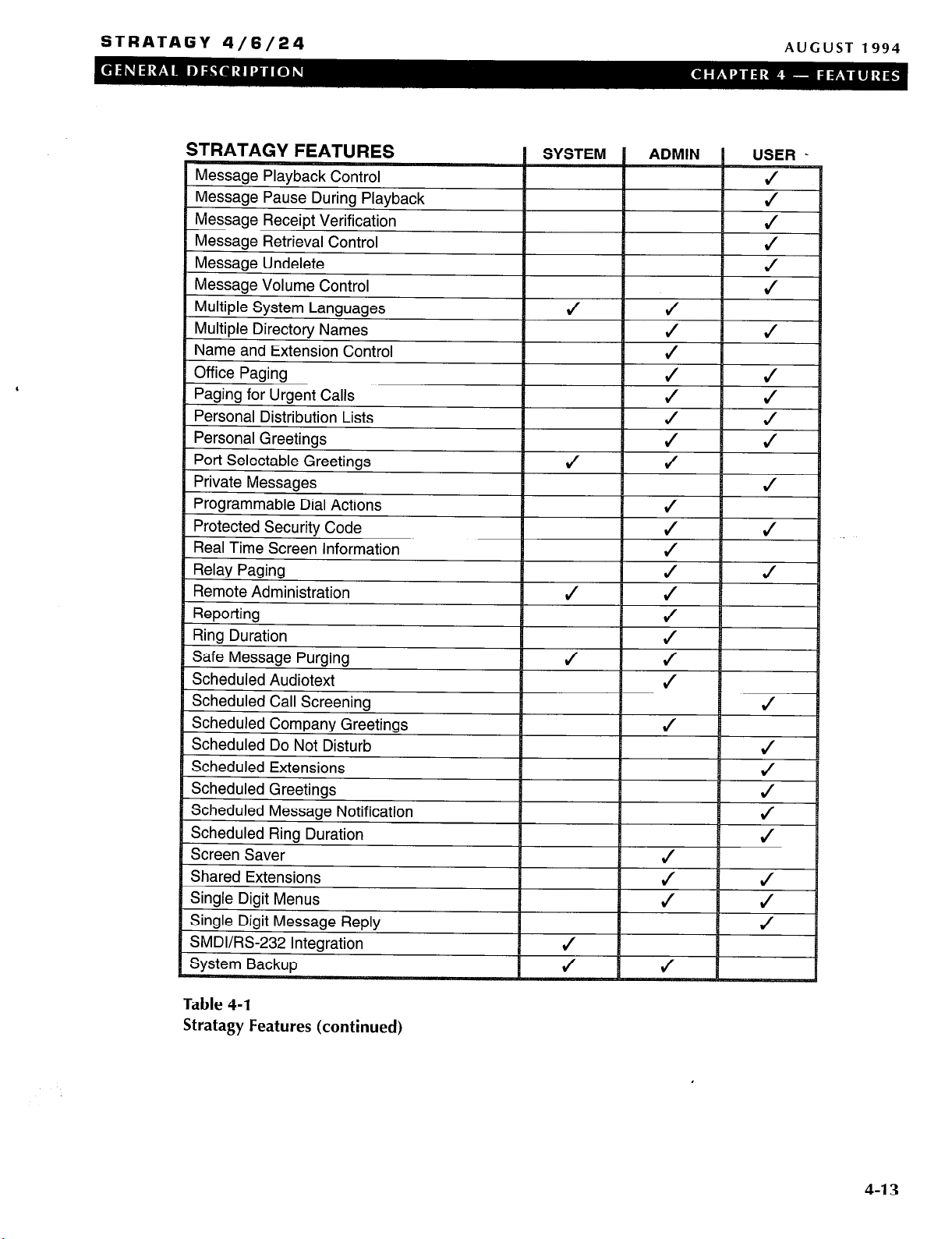
STRATAGY 4/6/24
AUGUST 1994
Table 4-1
Stratagy Features (continued)
,
4-l 3

STRATAGY 4/6/24
Table 4-l
Stratagy Features (continued)
AUGUST 1994
USER
4-l 4
Table 4-2
Stratagy Feature Differences by System
NOTE:
In addition, Stratagy 24 systems support four out of five
serial communication port (RS-232) options:
W Fax Modem 1
n Fax Modem 2
n Remote Maintenance
n IVR Host Connectivity
H SMDI Integration
A maximum of up to 4 of these options may be configured
for each Stratagy 24 system.
.:
,

STRATAGY 4/6/24
AUGUST 1994
CHAPTER 5
SYSTEM SPECIFICATIONS
This chapter provides specifications for various aspects
of the Stratagy systems. The provided information details
the systems’ physical and functional characteristics.
WEIGHT
30 Ibs.
POWER REQUIREMENTS
115 VAC at 6 amps (50/60 Hz)
230 VAC at 3.5 amps @O/60 Hz)
HEAT DISSIPATION
Maximum 200 watts
STRATAGY 4
685 BTU per hour
CONFIGURATION
‘
n A 486SX computer running at a minimum of 25MHz
n A minimum of 2MB of RAM
4 A hard disk drive with DOS
n One 3.5” diskette drive
4 Supports only FAX tone detection feature
n Capacity of two or four ports with six hours of
message capacity
n Integration with DK8 and DK16 only
n Optional 2400 baud external modem
DIMENSION
Height - 16”
Width - 7”
Depth - 15”
STRATAGY 24
CONFIGURATION
n A 486SX computer running at a minimum of 25MHz
n A minimum of 4MB of RAM
n A hard disk drive with DOS
n One 3.5” diskette drive
n Keyboard and monitor
n Optional 2400 baud external Modem
n Full fax capabilities
W Up to 24 ports
H Storage capacity of six, 20 or 33 hours
n Three different disk storage capacities
DIMENSION
WEIGHT
29 Ibs.
POWER REQUIREMENTS
115 VAC at 6 amps (50160 Hz)
230 VAC at 3.5 amps (50/60 Hz)
HEAT DISSIPATION
Maximum 200 watts
685 BTU per hour
STRATAGY 6
CONFIGURATION
n A 486SX computer running at a minimum of 25MHz
n A minimum of 2MB of RAM
n A hard disk drive with DOS
n One 3.5” diskette drive
n Supports only FAX tone detection features
n Capacity of two, four or six ports with six hours of
message capacity
System
Height - 6.2”
Width - 16.7” 12.8”
Depth - 16.7”
WEIGHT
System and keyboard - 38 Ibs.
Monitor - 20 Ibs.
POWER REQUIREMENTS
115 VAC at 6 amps (50160 Hz)
230 VAC at 3.5 amps (50160 Hz)
HEAT DISSIPATION
Maximum 200 watts
685 BTU per hour
MONITOR
POWER REQUIREMENTS
100 - 240 VAC at 0.5A amps (50160 Hz)
Monitor
13.3”
12.6”
DIMENSION
Height - 16”
Width - 7”
Depth - 15”
HEAT DISSIPATION
Maximum 50 watts
200 BTU per hour
5-1
STRATAGY 4/6/24
Strata=& / (o”i 1~
INSTALLATION AND MAINTENANCE MANUAL
INSTALLATION SECTION
SEPTEMBER 1994
Chapter 1
Chapter 2 _ _ _ - _ - _ - _ _
Chapter 3
Chapter 4
Chapter 5 _ - _ - - - - - - _
AppendixA ---------
1
3
_ - _ - - - - - - _
_ _ _ _ _ - _ - _ _
_ _ _ - _ - _ - _ _
AtoZ KELLATRONICS, INC
Introduction
Before You Install
Installing the Hardware
Accessing Stratagy
Configuring and Backing Up Stratagy
Checklists and Forms
STRATAGY 4/6/24
INSTALLATION AND MAINTENANCE MANUAL
INSTALLATION SECTION
SEPTEMBER 1994
CHAPTER 1
INTRODUCTION

STRATAGY 4 / 6
/ 2 4 INSTALLATION AND MAINTENANCE MANUAL
TABLE OF CONTENTS
Chapter 1 - Introduction
SEPTEMBER 1994
PARAGRAPH
1
2
3
3.1
3.2
4
,
4.1
4.2
5
6
SUBJECT
Purpose ________________________________________----
Organization ____________________________________
Reference Documentation-------------
____________________---------------------------------------------
____________________------------------------------------------------
_____-_________--___--------------
__________--_--__-__-------------------
Sections of this Manual ________________________________________----------------------------------------------Additional Reference Documentation ________________________________________-----------------------------
Assumptions About the Installer ----
Knows Stratagy and the Telephone System ________________________________________-------------------Trained Installer Familiar with PCs ________________________________________--------------------------------
System Mnemonics/Terms ____________________--------------------------------------------- ------ --__--------- -
____________________--------------------------------------------
---------- 1-l
Use of Notes, Cautions, and Warnings ____________________------------------------------ ------ ------------- -
PAGE
1-l
1-l
l-l
1-l
1-l
l-1
1-l
l-2
l-3
l-i

STRATAGY
4/6/24
INSTALLATION AND MAINTENANCE MANUAL
SEPTEMBER 1994
CHAPTER 1
INTRODUCTION
1 PURPOSE
The Installation section of the Sfrafagy lnsfa//afion and
Maintenance Manual provides detailed step-by-step
instructions for installing and maintaining Stratagy voice
processing systems.
This chapter provides an overview of the organization of
‘
the manual; a list of reference documentation that
supports the system; the assumptions about the installer;
a list of system mnemonics and terms; and the use of
notes, cautions, and warnings.
2 ORGANIZATION
This manual is organized in modular chapters for easy
removal and replacement of updated materials. The
chapters in this section are as follows:
Chapter 1 Introduction
Fault Finding: Describes the procedures used to
diagnose and correct faults.
Maintenance and Upgrades: Provides instructions on
maintaining and upgrading Stratagy systems.
Operating Procedures: Consists of the User Guide
reference document. Describes the telephone
operating procedures for the telephone user.
Incorporates the Quick Reference Guide, a concise
guide for Stratagy users.
Technical Bulletins: Provide important updates to the
Stratagy documentation.
3.2 ADDITIONAL REFERENCE
DOCUMENTATION
In addition, the Stratagy systems are supported by the
following complement of reference documentation.
Feature Description: A brief description of the features
of the Stratagy systems.
User Guide: Describes the telephone operating
procedures for the telephone user.
Quick Reference Guide: A concise guide for Stratagy
users.
.
Chapter 2 Before You Install
Chapter 3 Installing the Hardware
Chapter 4 Accessing Stratagy
Chapter 5 Configuring and Backing Up Stratagy
Appendix A Checklists and Forms
3 REFERENCE DOCUMENTATION
Reference documentation for the Installation section
consists of the remaining sections of the lnsfallafion and
Maintenance Illlanual and additional Stratagy
documentation.
3.1 SECTIONS OF THIS MANUAL
The lnsfallafion and Maintenance Manual consists of the
following sections.
General Description: Reference document that provides
an overview of the Stratagy systems. Describes their
hardware and features. Available as a stand-alone
document.
Installation: Designed for the installer, provides detailed
step-by-step instructions for installing and configuring
Stratagy systems (this section).
Programming: Provides detailed instructions for
operating, customizing, and administrating Stratagy
systems.
4 ASSUMPTIONS ABOUT THE
INSTALLER
4.1 KNOWS STRATAGY AND THE
TELEPHONE SYSTEM
To install, upgrade, or maintain the system, you need to
know the following about Stratagy:
n Features (refer to the Sfrafagy General Description)
n Operation, customization, and administration (refer to
the Programming section)
In addition, you need to know about the telephone
system to which you will connect Stratagy. Refer to the
appropriate installation documentation.
4.2 TRAINED INSTALLER FAMILIAR WITH
PCS
This manual is designed for a trained installer with some
familiarity of PCs and an understanding of telephone
systems. We assume you know the following:
n Computer terms, such-as: I/O, serial port, parallel
port, RS-232, RAM, and DOS.
n How to safely open a personal computer and
install/remove cards.
1-l

STRATAGY 4/6/24
INSTALLATION AND MAINTENANCE MANUAL
SEPTEMBER 1994
a
How to identify basic components of a personal
computer: e.g., motherboard, I/O controller, video
card, I/O ports, modem.
a
How to connect the monitor and keyboard, and how to
power on the computer.
a
How to type the underscore character ( _ ).
a
When to press the Enter key.
a
Telephony terms, such as: station side, CO, singleline, hunt group, coverage path, flash-hook, call
forward on ring-no-answer, call forward busy, DTMF,
and tone patterns.
,
a
The difference between an RJ-I 1 and RJ-14
connector.
a
The separation of the telephone switch and Stratagy.
a
How to use a line monitor (and have a line monitor) to
observe test calls.
If you are unfamiliar with any of the above, please find
out before you attempt to install Stratagy. Toshiba
Technical Support will be happy to answer your questions
regarding the above.
5 SYSTEM MNEMONICS/TERMS
The following mnemonics identify the system’s hardware,
operation, and features.
BPS: Bits Per Second - Unit of measure that refers to
the transmission speed (baud rate) of electronic
signals. Used when describing modem operation.
CO: Central Office - Facility which houses switching
equipment that provides telephone service (CO lines,
Centrex lines, etc.) for the immediate geographical
area.
DID: Direct Inward Dialing - Feature of PBX and Centrex
telephone systems which allows callers to dial from
the public network to a wanted extension without
operator intervention.
DK: Digital Key.
DTMF: Dual tone Multi-frequency - Push-button tone
dialing.
or accessed through the serial ports of the Stratagy
system, possibly connecting to a mainframe or other
data server.
Once a response has been determined from the
database, the Stratagy system may be programmed
to play this data back to the caller in a number of
different ways: as a date, time, monetary value (in
dollars and cents), or simply as a number. The value
may be combined with other custom-recorded
prompts, so that the system could, for example,
respond to a caller with the message “Your order for
6 items will be shipped on July 17, 1994.” The
number six and
provided by the database, while the phrases “Your
order for” and “items will be shipped on” would be
recordings that the System Administrator would
make.
MODEM: Modulator-Demodulator - Device used
primarily for converting digital signals into quasianalog signals for transmission, and reconverting
upon reception.
PBX: Private Branch Exchange - Industry-standard term
which refers to a telephone switch, usually on-
premises, which serves an individual company, and
is connected to a public telephone exchange through
the CO.
PC: Personal Computer.
PCB: Printed Circuit Board.
PORT: There are two types of ports: physical and logical.
A physical port is an actual station circuit location; a
logical port is the set of characteristics - features,
station intercom number, etc. - assigned to the
physical port. Logical ports are mobile; they can be
moved from one physical port to another.
RAM: Random Access Memory - Type of system
memory that holds individual system configuration
and features programming. RAM is read/write
memory, and can easily be revised in programming.
RNA: Ring No Answer.
ROM: Read Only Memory - Type of system memory that
holds static software that comprises the mechanics
of the features’ functions.
the date
in this example would be
,;
I/O: Input/Output.
IVR: Interactive Voice Response - An application that will
prompt the user for input (using a custom prompt),
wait for the user to enter a DTMF response, which
will be stored into a variable, and then use that
information to access a database to formulate a
response. Databases may be on the hard disk of the
Stratagy system, accessed remotely over a network,
l-2
SMDI: Simplified Message Desk Interface - type of
integration that uses an RS-232 serial link.
SMDR: Station Message Detail Recording.
USER ID: Unique Stratagy record that provides call
processing control - records messages from callers,
provides information to callers, or controls the flow of
a call.
::
-’

STRATAGY 4/6/24
INSTALLATION AND MAINTENANCE MANUAL
6 USE OF NOTES, CAUTIONS,
AND WARNINGS
Notes - Elaborate specific items, or reference other
information.
Important Notes - Call attention to important
instructions or other information.
Cautions - Advise you that the equipment could be
damaged if the instructions are not followed closely.
Warnings - Alert you when the given tasks could cause
the technician personal injury or death.
SEPTEMBER 1994
l-3

STRATAGY 4/6/24
INSTALLATION AND MAINTENANCE MANUAL
INSTALLATION SECTION
SEPTEMBER 1994
CHAPTER 2
BEFORE YOU INSTALL

STRATAGY 4
/ 6 /
24
INSTALLATION AND MAINTENANCE MANUAL
TABLE OF CONTENTS
Chapter 2 - Before You Install
SEPTEMBER 1994
PARAGRAPH SUBJECT
1
2
3
4
5
6
Introduction ________________________________________------------------------------- ----------------------------------
The Reference Documentation ____________________-------------------------- ----------------------------------
Conduct a pre-installation Survey ____________________------- --- ------- ------------ _________---_______-------Determine Stratagy’s Configuration and Integration ____-________----- ------ ---- ----------------------Customize User ID Mailboxes ____________________--------------------------- ----- _----- ----------------------Select and prepare the Hardware Site ____________________---------------- ---- -_----- -----------------------
PAGE
2-j
2-j
2-l
2-j
2-2
2-2
2-i

STRATAGY 4/6/24
INSTALLATION AND MAINTENANCE MANUAL
CHAPTER 2
SEPTEMBER 1994
l
Number of locations
H Telephone system to which you will connect Stratagy
BEFORE YOU INSTALL
1 INTRODUCTION
The pre-installation requirements include:
n
Knowing the reference documentation.
n
Conducting a pre-installation survey to determine how
to configure and customize the Stratagy system.
n
Determining Stratagy’s configuration and integration.
n
Customizing User ID mailboxes to define the
automated attendant and voice messaging system.
n
Selecting and preparing the hardware site.
To
assist you in tracking your progress in meeting these
requirements, we provide the Stratagy Pre-Installation.
(We also provide the Stratagy Installation Checklist to
help you verify that you have completed the necessary
steps involved in installation.) See Appendix A,
“Checklists and Forms.”
- -
2 THE REFERENCE
DOCUMENTATION
To install, upgrade, or maintain the system, you need to
know the following about Stratagy.
n Features (refer to the Stratagy General Description)
n Installation (refer the Installation section).
n Operation, customization, and administration (refer to
the Programming section).
In addition, you need to know about the telephone
system to which you will connect Stratagy. Refer to the
appropriate installation documentation.
3 CONDUCT A
PRE-INSTALLATION SURVEY
When conducting a pre-installation survey, obtain
information about the company, its telephone system,
and the desired auto attendant and voice mail functions.
As appropriate, use the items suggested below and
include additional questions.
n The company
l
Number of employees
l
Number of employees using mailboxes
l
Manufacturer, model, and software release
l
Number of Central Office lines
l
Number of single line stations
n
Auto
attendant information
l
Number of companies using system
l
Whether primary answering position
l
Company greetings and instructions
l
Menus (sales, service, etc.)
n Voice mail information
l
Number of employees requiring voice mailboxes
l
Message waiting lights
l
Notification requirements
l
Directory requirements
4 DETERMINE STRATAGY’S
CONFIGURATION AND
INTEGRATION
Determining Stratagy’s configuration and integration
definitions involves the following. Reference Chapter 5
(“Configuring and Backing Up Stratagy”) for details.
Defining Stratagy system configuration options:
n
setting system-wide parameters for Stratagy control,
including system password, timeout values, computer
configurations, and per port options.
n
Defining the telephone system dial codes, telephone
system tone patterns, and system integration
patterns.
Note that each Stratagy system has been pre-
installed at the factory for out-of-box (Plug and Play)
operation on a specific Toshiba telephone system as
follows:
Stratagy 4 with Strata DK8
Stratagy 6 with Strata DK16
Stratagy 24 with Strata DK280A
All dial codes, tone patterns, and integration patterns
specific to the above system have been pre-installed
at the factory for each Stratagy system.
IMPORTANT NOTE:
The above Strata DK must be configured for
the appropriate voile mail system settings
individually. See the specific Strata DK
Installation and Maintenance manual for
these procedures.
2-1

STRATAGY 4/6/24
INSTALLATION AND MAINTENANCE MANUAL
SEPTEMBER 1994
* If you have a Toshiba telephone system, Stratagy
will automatically define these parameters once
you
select the appropriate system during
installation (if not pre-installed).
a If you are defining how Stratagy and another
manufacturer’s telephone systems communicate
together, you will also need to reference the
telephone
documentation.
manufacturer’s installation
5 CUSTOMIZE USER ID
‘
MAILBOXES
Customize Stratagy by programming the User IDS to
define the automated attendant and voice messaging
system. For details, see the Programming section.
Note that with Toshiba Plug and Play, the Strata DK
default station (extension number) User ID mailboxes
have been pre-installed for the specific Stratagy and
Strata DK systems described above. n
For your convenience, Appendix A (“Checklists and
Forms”) provides the following: Users Form, Auto
(Scheduling) Form, Notify Form, and Greeting Scripts
Form.
6 SELECT AND PREPARE THE
HARDWARE SITE
Since the Stratagy system PC hardware and the
telephone system must be physically connected, locate
the PC by the telephone system. A remote system can
be located anywhere it is appropriate to place a PC.
Power Requirements -We recommend the following for
the Stratagy system PC desktop and tower:
n A 1.5 A circuit breaker and dedicated AC circuit (does
not have an ON/OFF wall switch
power turn-off)
n A surge protector with a light that indicates whether or
not the protector is operational
E
nvironmental Considerations - Any place appropriate
for a PC, including:
n
Dry and clean, well ventilated, well illuminated, and
easily accessible
Not subject to extreme hot or cold; corrosive fumes,
dust, or other airborne contaminants; or excessive
vibration
For more details about environmental and electrical
specifications, see Chapter 3, “Installing the Hardware.”
to avoid accidental
_
2-2

STRATAGY 4/6/24
INSTALLATION AND MAINTENANCE MANUAL
INSTALLATION SECTION
SEPTEMBER 1994
CHAPTER 3
INSTALLING THE HARDWARE

STRATAGY 4/6/24
INSTALLATION AND MAINTENANCE MANUAL SEPTEMBER 1994
TABLE OF CONTENTS
Chapter 3 - Installing the Hardware
PARAGRAPH SUBJECT
1 1 ntroduction ________________________________________-----------------------------------------------------------------
2 The Hardware ___________ - ________________________________________--------------------------------------------------
3
4
5 Installing Stratagy Voice Boar& ________________________________________---------------------------- -- --------
What Comes Shipped ________________________________________---------------------------------------------------
Inspecting and Unpacking the System ________________________________________---------- -- -------- ---- ------
PAGE
3-t
3-t
3-I
3-I
3-l
5.1 Stratagy Voice Board Code and Activation Key-Number ------------------------------------------- 3-l
5.2
6
6.1
6.2
Addressing
Setting Up Stratagy System Hardware ________________________________________------------------------------
Setting Up the Stratagy 4 and 6 ________________________________________-----------------------------------Setting
and
Up the
Installing
Stratagy
Stratagy
Voice Boards ________________________________________--------------
24 ________________________________________-------------------------------------------
7 Physically Connecting Stratagy to Your Telephone System-------------------------------------------
7.1 Connecting to a Telephone System that Uses RJ-14 Jacks ----------------------------------------
3-4
3-5
3-5
3-8
3-8
3-l 0
7.2 Connecting to a Telephone System that Uses RJ-11 Jacks ---------------------------------------- 3-11
7.3 Connecting to a Telephone System that Uses Modular and Split Block ------------------------- 3-l 1
Verify
8
FIGURE LIST
FIGURE TITLE
3-l
3-2
3-3
3-4
3-5
3-6
3-7
3-8
3-9
3-10
3-11
Basic Functions -: ---------------------------------------------------------------------------------------.-- 3-t 3
Stratagy
Stratagy
The
Stratagy
Stratagy
4
and 6 Hardware Components ________________________________________---------------------------
24
Hardware Components ________________________________________----------------------------------
Stratagy
Voice Board ________________________________________----------------------------------------------
4
and 6 Voice Board Installation ________________________________________--------------------------
24
Voice Board Installation ________________________________________---------------------------------
Stratagy 4 and 6 Front and Back Panels
(Sample Stratagy 6 with 6 Voice Board and 2 COM Ports)---------------------------------------
Stratagy 24 Front and Back Panels (Sample Stratagy 24 with 24 Voice Board Ports) ---------
Stratagy
Voice Board Poti
Numbering
________________________________________------------------------------
Connecting Stratagy to a Telephone System that Uses RJ14 Jacks-------------------------------Connecting Stratagy to a Telephone System that Uses RJl 1 Jacks-------------------------------Connecting Stratagy to a Phone System that Uses Modular and Split Block ---------------------
PAGE
3-2
3-3
3-5
3-6
3-7
3-8
3-9
3-10
3-l 1
3-l 1
3-12
TABLE LIST
TABLE
3-l
3-2
3-3
TITLE
Stratagy
Stratagy
Stratagy Hardware Environmental and Electrical Specification Summary -------------------------
4
and 6 Hardware Specification Summary ________________________________________-------------
24
Hardware Specification Summary ____________________----------------------------------------
PAGE
3-2
3-3
3-4
3-i

STRATAGY 4/6/24
INSTALLATION AND MAINTENANCE MANUAL SEPTEMBER 1994
CHAPTER 3
INSTALLING THE HARDWARE
1 INTRODUCTION
This chapter describes the Stratagy hardware and
provides step-by-step instructions on installing the
Stratagy 4, 6, and 24 systems.
2 THE HARDWARE
Stratagy 4 and 6 - This system consists of a PC tower.
It contains 2 or 4 ports, and 6 hours of disk storage.
It may be expanded to a maximum of 6 ports. A lap-
top PC with Stratagy Remote software installed and
a null modem cable is required. An external modem
is available as an option. See Figure 3-l for the
major hardware components. For the specification
summary, see Table 3-I.
Stratagy 24 - This system consists of a desktop PC,
monitor, and keyboard. It contains 4 ports, and either
6, 20, or 33 hours of disk storage. It may be
expanded to a maximum of 24 ports. An external
modem is available as an option. See Figure 3-2 for
the major hardware components. For the
specification summary, see Table 3-2.
For the Stratagy hardware environmental and electrical
summary for Stratagy 4, 6, and 24, see Table 3-3.
3 WHAT COMES SHIPPED
Stratagy 4 and 6 ships with the following:
n PC tower appropriately equipped and all necessary
software pre-installed on the hard disk
H Documentation package (DOC PAK)
Stratagy 24 ships with the following:
n
PC desktop appropriately equipped and all necessary
software pre-installed on the hard disk
n
Monitor and keyboard
n
Documentation package (DOC PAK)
4 INSPECTING AND UNPACKING
THE SYSTEM
Use the following procedures when inspecting and
unpacking the system:
1. When you receive the system, examine all
packages carefully and note any visible damage. If
you find any damage, do not open the packages.
Contact the delivery carrier immediately and make
the proper claims.
2. Check the system against the packing list and
inspect all equipment for damage. If equipment is
missing or damaged, contact your supplier
immediately.
3. Retain the original packaging materials for re-use
when transporting system hardware.
4. Place the key for the PC’s lock in a safe place. You
may want to use the keys to prevent unauthorized
keyboard access to Stratagy.
5 INSTALLING STRATAGY VOICE
BOARDS
Stratagy systems can be expanded to their maximum
capacity by installing additional Stratagy 2- or 4-port
voice boards. This section discusses:
n Stratagy voice board code and activation key-number
n Addressing and installing Stratagy voice boards
.
5.1 STRATAGY VOICE BOARD CODE AND
ACTIVATION KEY-NUMBER
Only Stratagy voice boards can be used in a Stratagy
system. In addition, each Stratagy system has a unique
activation key-number that matches the Stratagy
software to a specific Stratagy voice board.
IMPORTANT NOTE:
Use only Stratagy voice boards supplied by
Toshiba in your Stratagy system. Non-
Stratagy voice boards will cause your entire
system to be non-operational.
Stratagy voice boards are manufactured by Rhetorex,
Inc. and are configured with a unique Stratagy code
allowing them to work with a Stratagy system. You
install and use only Stratagy voice boards supplied by
Toshiba. Other Rhetorex voice boards manufactured for
other voice processing systems are not configured with
the unique Stratagy code. Therefore, a non-Stratagy
voice board installed in a Stratagy system will cause the
entire system to become non-operational. All non-
Stratagy voice boards must be removed to allow the
Stratagy system to function. In a Stratagy 24 system, the
non-Stratagy voice boards will be identified on the
monitor. Non-Stratagy voice boards will also be identified
in the Stratagy 4 and 6 systems when these systems are
accessed using a laptop PC with Stratagy Remote
software via local or remote access.
IMPORTANT NOTE:
Each Stratagy voice processing system has a
unique activation key-number entered during
manufacturing that matches the Stratagy
software to a Stratagy voice board. The
software will not work with any other voice
board.
must
3-l

STRATAGY 4/6/24
INSTALLATION AND MAINTENANCE MANUAL
SEPTEMBER 1994
Figure 3-l
Stratagy 4 and 6 Hardware Components
Tower Hardware
CPU
Hard Disk Drive
Floppy Drive
RAM
486SX CPU @ 25 MHz
6 hours net storage
3.5” diskette drive (1.44MB)
2MB
Other Hardware
External Modem
2400 baud modem (optionally equipped, but required for remote access)
Capacities
Ports
Software
2,4 or 6 ports
DOS
Stratagy voice processing software, host, and necessary utilities
Table 3-1
Stratagy 4 and
3-2
6 Hardware Specification Summary

STRATAGY 4/6/24
INSTALLATION AND MAINTENANCE MANUAL
SEPTEMBER 1994
I
Figure 3-2
Stratagy 24 Hardware Components
Desktop Hardware
CPU
Hard Disk Drive
Floppy Drive
RAM
Other Hardware
Monitor
Keyboard
External Modem
Capacities
Ports
Software
486SX CPU @ 25 MHz
6, 20, or 33 hours of net storage
3.5” diskette drive (1.44MB)
4MB
VGA
101 -key keyboard
2400 baud modem (optionally equipped, but required for remote access)
4, 6, . . .
DOS
Stratagy voice processing software, host, and necessary utilities
24 ports
Table 3-2
Stratagy
24 Hardware Specification Summary
3-3

STRATAGY 4/6/24
INSTALLATION AND MAINTENANCE MANUAL
SEPTEMBER 1994
Environmental
Conditions
Electrical
Requirements
(AC Input)
Operating Temperature 39.2”F to 104°F (4°C to 40°C)
Storage Temperature 104°F to 140°F (-40°C to 60°C)
Operating Humidity
Stratagy 4, 6 or 24 115 VAC, at 6 amps (50/60 Hz)
Monitor
20% to 80% (non-condensing)
230 VAC at 3.5 amps (50/60 Hz)
115 or 230 VAC at 0.5 amps (50/60 Hz)
(Provide host system with 15 A circuit breaker and dedicated circuit)
Heat Dissipation
Analog Interface
‘
Stratagy 4, 6, or 24 Maximum 200 watts, 685 BTU per hour
Monitor Maximum 50 watts, 200 BTU per hour
Telco types Loop Start, OPX
Connection Single line, RJ-14C jacks
Impedance 600 ohm nominal
Frequency response 300 - 3200 Hz
Ring detect
Loop current range 20 - 120 mA polarity insensitive
Transfer signaling Hook-flash
Input level -3 dB maximum, 130 dB/minimum
Output level -3 dB maximum, 30 dB/minimum
DTMF receive 16 tones (0 - 9, *, #, A - D)
Minimum tone duration 45 ms
Minimum tone detect -29 dB/minimum
Twist range
DTMF transmit 16 tones (0 - 9, *, #, A - D)
Minimum tone duration
Transmit level -7 dBm nominal
Twist range 2-3dB
Progress Tones
Frequency response 200 - 300 Hz +3 dB/minimum
Speech Parameters -13 dB/minimum average transmit level for a -32 dBm receive level
Voice Coding Scheme 64 Kbs u-Law PCM, 32 Kbs ADPCM compression
40 - 130 Vrms, 15.3 - 68.0 Hz
+-IO dB
50 ms
Standard and proprietary, in 350 - 640 Hz frequency range
Table 3-3
Stratagy Hardware Environmental and Electrical Specification Summary
Each Stratagy voice processing system has a unique
activation key-number that matches the Stratagy
software to a Stratagy voice board. This number is
entered into the system during manufacturing.
The activation key-number is written on a piece of
paper shipped with the Stratagy system. Store the
number in a safe place.
The activation key-number
must be entered to allow the
5.2 ADDRESSING AND INSTALLING
STRATAGY VOICE BOARDS
Stratagy systems may be expanded to their maximum
capacity by installing additional Stratagy 2- or 4-port
voice boards. Installing a voice board into a Stratagy
system PC involves addressing the board before
installing it.
Stratagy system to operate under the following
conditions:
n The Stratagy factory-installed voice board is removed.
H The Stratagy hard disk drive is replaced or upgraded.
n The Stratagy system software is re-installed or
upgraded.
n Fault isolating or troubleshooting a Stratagy system
under direction of Toshiba Technical Support.
In most cases, you must re-enter the original activation
key-number shipped with the system. In other cases,
you must obtain a new activation key-number
contacting Toshiba.
5.2.1 ADDRESSING THE VOICE BOARD
In order for Stratagy to recognize each voice board in a
system, each voice board is assigned a unique address.
The address of the first voice board is 300; the second,
address 301; the third, address 302, etc.
To set a voice board’s address, you need to arrange the
10 jumper pins on the voice board in the correct manner.
The jumper pins are located along the top middle-right of
the board as you are looking at the component side of
the board with the 4-wire jacks on the right. See Figure
by
3-3.
3-4

STRATAGY 4/6/24
INSTALLATION AND MAINTENANCE MANUAL
SEPTEMBER 1994
Figure 3-3
The Stratagy Voice Board
Voice board 1 is factory installed and normally shipped
with address 300 (setting for board 1). Additional boards
are packaged separately. Set the jumper pins for each
voice board as follows. Note the following:
0: both pins are not covered/connected by a black
jumper pin (open)
7: both pins are covered/connected by a black jumper
pin (closed)
Board 1
Board 2 Address 301
Board 3
Board 4
Board 5
Board 6 Address 305 0101111100
Address 300 1111111100
0111111100
Address 302 1011111100
Address 303 0011111100
Address 304 1101111100
SHOWN:ADDRESS300
6. Close the computer, plug in the power cord, and
turn on the power. Stratagy should automatically
recognize the additional ports.
Use only Stratagy voice boards supplied by
Toshiba. Non-Stratagy voice boards will
cause your entire system to be nonoperational.
(SETTING FOR BOARD
IMPORTANT NOTE:
1)
6 SETTING UP STRATAGY
SYSTEM HARDWARE
5.2.2 INSTALLING THE VOICE BOARD
To install the voice board in the Stratagy system, do the
following. See Figures 3-4 and 3-5 for the voice board
slots in the Stratagy 4 and 6 and Stratagy 24,
respectively.
1. If installing voice boards in an existing system,
from the Stratagy Main Menu shut down Stratagy
(see Chapter 4, “Accessing Stratagy” for details).
2. Turn computer’s power off.
3. Unplug the power cord.
4. Open the computer and locate the first available
full length slot.
5. Remove the back slot cover and install the voice
board while taking care to properly slide the end of
the voice board into the rear card guide. Repeat
this for each voice board you are installing.
6.1 SETTING UP THE STRATACY 4 AND 6
To set up Stratagy 4 and 6, do the following. For a
diagram of the front and back panels, see Figure 3-6.
1. Place the PC tower in the site determined by the
pre-installation survey.
2. Make sure the selectable power switch is at 11 OV
or 22OV, depending upon available input power.
3. Connect the PC power cable.
n If using 11 OV AC, connect the PC power cable
to the rear of the PC and to the dedicated 11 OV
AC outlet. (We recommend you use a surge
protector.)
n If using 220V AC, connect the PC power cable
to the rear of the PC and to the dedicated 220V
AC outlet. (We recommend you use a surge
protector.)
,
3-5

STRATAGY 4/6/24
INSTALLATION AND MAINTENANCE MANUAL
Shown: Installing Voice Board 1.
SEPTEMBER 1994
Figure 3-4
Stratagy 4 and 6 Voice Board Installation
3-6

STRATAGY 4/6/24
INSTALLATION AND MAINTENANCE MANUAL
Shown: Installing Voice Board 1.
Other boards not shown.
I I
SEPTEMBER 1994
Figure 3-5
Stratagy 24 Voice Board Installation
3-7

STRATAGY 4/6/24
INSTALLATION AND MAINTENANCE MANUAL SEPTEMBER 1994
AUXILIARY
POWER
OUTLET
110122ov
POWER SWITCH
AIC POWER
CORD
CONNECTOR
- POWER
(ON/OFF)
COM2
- KEY
LOCK
(default
local access) LPTl ~
PARALLEL
PRINTER
PORT
not
used
COM1
(default
remote access)
not used
not used
PORTS 516
PORTS l/2
PORTS 314
Figure 3-6
Stratagy 4 and 6 Front and Back Panels (Sample Stratagy 6 with 6 Voice Board and 2 COM Ports)
6.2 SETTING UP THE STRATACY 24
To set up Stratagy 24, do the following. For a diagram of
the front and back panels, see Figure 3-7.
1. Place the Stratagy system PC on a table or desk
in the site determined by the pre-installation
survey.
2. Place the keyboard in front of the PC desktop.
I If using 220V AC, connect the PC power cable
to the rear of the PC and to the dedicated 220V
AC outlet. (We recommend you use a surge
protector.)
7. If installing a printer, connect the 25pin data cable
from the printer to the RS-232 printer pot-t (LPTI)
on the back of the Stratagy system. Tighten the
screws. The printer must have a parallel interface.
3. Connect the round keyboard connector to the
matching connector located in a round hole in the
rear panel.
4. Place the monitor on top of the Stratagy system
PC.
5. Connect the 15pin monitor data cable to the
7 PHYSICALLY CONNECTING
STRATAGY TO YOUR
TELEPHONE SYSTEM
video/printer adapter card’s 15pin connector
located on the rear panel. Tighten the screws with
a small flathead screwdriver.
6. Connect the PC power cable.
Before connecting Stratagy to your telephone
sysfem, configure the yoke mail sysfem
IMPORTANT NOTE:
settings for your telephone system
q If using 11 OV AC, connect the PC power cable
to the rear of the PC and to the dedicated 1lOV
AC outlet. (We recommend you use a surge
individually. Refer to your telephone system’s
insfallation documentation.
protector.)
VOICE
BOARD
PORTS
1
-
3-8

STRATAGY 4/6/24
INSTALLATION AND MAINTENANCE MANUAL
POWER (ON/OFF)
SEPTEMBER 1994
VOICE BOARD PORTS
COM2 (default: fax 2)
COMl (default: fax 1)
COM4 (default: remote access) ~
COM3 (default: SMDI)
0
KEY LOCK @
PORTS13114 7
PORTS 15/16 7 1
PORTS 17/18 PORTS 19120
PORTS 21122
PORTS 23124
1
1
7 PORTS 9110
I
- PORTS 5/6
PORTS 1 l/l 2
PORTS 718
- PORTS l/2
“ORTS 314
0
POWER OUTLET
0
0
\
0
\
110/22OV POWER SWITCH ~ LPTl PARALLEL A
I
CORD CONNECTOR
A/C POWER
A
KEYBOARD 1
CONNECTOR
PRINTER PORT
--
MONITOR
CONNECTOR
I
I
Figure 3-7
Stratagy 24 Front and Back Panels (Sample Stratagy 24 with 24 Voice Board Ports)
3-9

STRATAGY 4/6/24
INSTALLATION AND MAINTENANCE MANUAL SEPTEMBER 1994
Physically connect Stratagy to your telephone system. To
do this you need to know:
n Customer-Supplied Parts - All modular cords,
connectors, cables, and connection blocks are
customer-supplied.
n Location of the Ports on the Voice Board - On a
voice board with two connectors, the top connector
represents the first two ports, and the bottom
connector represents the second two ports, for a total
of four ports. See Figure 3-8.
n Numbering of Ports - Ports are numbered from 1 up
to a maximum of 24 (depending upon your system
hardware), with port 1 starting with the lowest
addressed voice board. See Figures 3-6 and 3-7.
n RJ-14 Modular Jacks and Voice Board Ports -
Each connector on a voice board is an RJ-14 type
module jack that supports two ports, where the inner pair
of wires is one port and the outer pair is the other port.
n RJ-14 versus RJ-11 Modular Jacks - RJ-14 system. See Figure 3-g.
modular jacks use a standard 2-pair line cord, which
represents two analog, or single-line, extensions. RJ-
11 jacks use only the inner pair of wires, which
represents only one analog extension.
n Stratagy may connect to the telephone system in
three ways. first two lines.
l
Directly using RJ-14 modular cords. See
‘Connecting to a Telephone System that Uses RJ-
14 Jacks.”
l
Directly using RJ-14/RJ-11 split modular cords.
See “Connecting to a Telephone System that Uses
RJ-11 Jacks.”
l
Indirectly using RJ-14 modular cords, 625type
modular blocks, a 66M150 type split block, and 25
pair cable with AMP connector. This is typical of
Toshiba Strata DK and Perception telephone
systems. See “Connecting to a Telephone System
that Uses Modular and Split Block.”
7.1 CONNECTING TO A TELEPHONE
SYSTEM THAT USES RJ-14 JACKS
If your telephone system uses RJ-14 modular jacks, use
a standard e-pair line to connect Stratagy to the phone
Connect the system as follows:
,
. Plug one end of an RJ-14 connector into
Stratagy’s voice board jack for ports 1 and 2; the
other end into the telephone system’s jack for the
JUMPER PINS
Figure 3-8
Stratagy Voice Board Port Numbering
-
-
-
4
PORT 1
3
PORT 3
PORT 2
PORT 4
3-10

STRATAGY 4/6/24
INSTALLATION AND MAINTENANCE MANUAL
SEPTEMBER 1994
TO TELEPHONE SYSTEM
>.:. ->.., RJ-14
STRATAGY
VOICE BOARD
JACK
.-
5 (,;-‘i
-,Jw... ___ ,
‘.“-_
--- -- -----_“:/ Js
_ .--. “l.,~..---’
--/
STANDARD 2-PAIR
TELEPHONE LINE
i ‘:
-...._
b.
1 ]
..i.;,
Figure 3-9
Connecting Stratagy to a Telephone System that
Uses RJ-14 Jacks
2. Plug one end of an RJ-14 connector into
Stratagy’s voice board jack for ports 3 and 4; the
other end into the telephone system’s jack for the
second two lines.
3. Continue the process until all voice board ports are
connected.
7.2 CONNECTING TO A TELEPHONE
SYSTEM THAT USES RJ-II JACKS
If your telephone system uses RJ-11 modular jacks, you
will need to use a splitter to connect Stratagy’s RJ-14
jacks to the phone system. That is because for RJ-11
connectors only two wires - the inner pair - are used.
(Also see “Connecting to a Telephone System that Uses
Modular and Split Block.“) See Figure 3-l 0.
Connect the systems as follows:
1. Make splitters by dividing one end of each RJ-14
connector into two RJ-11 connectors.
Attach the green and red wires (the inner pair
of the RJ-14 connector) to the inner pair of one
RJ-11 plug. Refer to this as the first RJ-I 1 plug.
Attach the black and yellow wires (the outer
pair of the RJ-14 connector) to the inner pair of
the other RJ-11 plug. Refer to this as the
second RJ-11 plug.
2. Connect Stratagy’s voice board ports 1 and 2 to
the first two lines on the telephone system by
inserting the following:
n the RJ-14 plug into the jack for Stratagy’s voice
board ports 1 and 2
n first RJ-11 plug into the telephone system’s jack
for the first line
TO TELEPHONE
SYSTEM
m
STRATAGY
VOICE BOARD , _
L RED
i-
GREEN LINE
BLACK
YELLOW
RED
GREEN
TELEPHONE
Figure 3-10
Connecting Stratagy to a Telephone System that
Uses RJ-11 Jacks
n second RJ-11 plug into the telephone system’s
jack for the second line
3. Continue the process until all voice board ports are
connected.
7.3 CONNECTING TO A TELEPHONE
SYSTEM THAT USES MODULAR AND
SPLIT BLOCK
Many telephone systems will require other types of
connections instead of directly to RJ-14 or RJ-11. This
type of connection is accomplished using 625type
modular blocks and telephone wire, and/or 66M150 split
blocks.
Connect the systems as follows:
1. Plug one end of an RJ-14 connector into
Stratagy’s voice board jack for ports 1 and 2; the
other end into a 625type or equivalent modular
block. Connect the wire to the telephone system
using the appropriate connector. A 66M150 split
block may also be used with bridging clips and as
shown in Figure 3-11. This is typical of Toshiba
Strata DK and Perception telephone systems.
2. Plug one end of an RJ-14 connector into
Stratagy’s voice board jack for ports 3 and 4; the
other end into a 625-type or equivalent modular
block. Connect the wire to the telephone system
using the appropriate connector. A 66M150 split
block may also be used with bridging clips and as
shown in Figure 3-11.
3. Continue the process until all voice board ports are
connected.
3-11

STRATAGY 4/6/24
INSTALLATION AND MAINTENANCE MANUAL
SEPTEMBER 1994
TO TELEPHONE
SYSTEM
BRIDGING
Cl IPS
-
MODULAR -
CORD
MODULAR BLOCK,
625TYPE OR
EQUIVALENT
STRATAGY VOICE
BOARD
Poti
3 and 4
NOTE:
4 port voice board is shown
66M150 SPLIT BLOCK
’
2 port voice board will have only
one modular jack.
Figure 3-l 1
Connecting Stratagy to a Phone System That Uses Modular and Split Block
3-12
5 R2
4 Ri
3 Tl
2 T2
PIN-OUT
w
N
u
Port
1 and ,2

STRATAGY 4/6/24
INSTALLATION AND MAINTENANCE MANUAL
SEPTEMBER 1994
8 VERIFY BASIC FUNCTIONS
Follow the instructions below to verify that the basic
functions of Stratagy are working once you have
connected the system or have moved Stratagy to a
different site.
Note that each Stratagy system has been pre-installed at
the factory for out-of-box (plug and play) operation on a
specific Toshiba telephone system. This includes the
integration and configuration parameters, default station
(extension number) User ID mailboxes, and company
greeting and instructions. The systems are:
Stratagy 4 with Strata DK8
Stratagy 6 with Strata DK16
Stratagy 24 with Strata DK280A
This is the out-of-box Toshiba Plug and Play operation for
all Stratagy systems. Therefore, whether or not you have
the specific telephone system associated with your
Stratagy 4, 6, or 24, you will be able to verify basic
functions.
IMPORTANT NOTE:
If you experience any problems, go to the
Fault Finding section before proceeding.
1. Verify that Stratagy is functioning and the boards
did not get dislodged during shipping. To do this,
power up the system. Let it proceed without any
action from you. Wait approximately 3 minutes. A
Stratagy 24 will display the Main Menu.
2. Verify that each port works. This process also
verifies voice playback and basic auto-attendant
functions. Dial the extension number for each port.
For each port Stratagy should:
n Answer and play the Toshiba Plug and Play
company greeting (“Thank you for calling...“),
greeting 1 in User ID mailbox 990.
n Continue to play the Toshiba Plug and Play
instructions greeting (“To reach the person.. .“),
greeting 1 in User ID mailbox 991.
3-13

STRATAGY 4/6/24
Stratagym@ / (o”i /m
INSTALLATION AND MAINTENANCE MANUAL
INSTALLATION SECTION
SEPTEMBER 1994
CHAPTER
4
ACCESSING STRATACY

STRATAGY 4/S/24
INSTALLATION AND MAINTENANCE MANUAL
TABLE OF CONTENTS
Chapter 4 - Accessing Stratagy
SEPTEMBER 1994
PARAGRAPH SUBJECT
1
2
3
3.1
3.2
3.3
4
4.1
4.2
4.3
Introduction ________________________________________------------------------------------------- ----- ----- -----------Using the Main Menu _______________________________________
Local Access ________________________________________----------------------------------------- ----- ----- ----- ----- --
Connecting the Cable ________________________________________--Preparing the Local System ____________________--------------------------------------- ----- ----- -- -------- -Using Stratagy Locally ________________________________________---------------------------------------------- --
Remote Access ________________________________________---------------------------------------- --- _____---------- --
Preparing the Stratagy System ____________________------------------------------------------------------- --
Preparing the Remote System _________________________
Using Stratagy Remotely ________________________________
FIGURE LIST
FIGURE
4-1
TITLE
Main Menu with Sample Data ____________________--------------------------------------- ------------ -------- 2
____________________---------------------------------
____________________--------------------------
____________________--------------------------------____________________---------------------------------
PAGE
4-1
4-1
4-2
4-2
4-2
4-2
4-3
4-3
4-3
4-3
PAGE
4-I

STRATAGY 4/6/24
INSTALLATION AND MAINTENANCE MANUAL
SEPTEMBER 1994
CHAPTER 4
ACCESSING STRATAGY
1 INTRODUCTION
When the Stratagy system powers up, the system
automatically displays the Main Menu. From the Main
Menu, you can customize User ID mailboxes, maintain
the system, and perform administrative functions. Or you
can shut down Stratagy and use the Stratagy
Configuration utility to backup or configure Stratagy with
your telephone system.
To perform these functions, the Stratagy 4 and 6, which
are not equipped with a monitor and keyboard, are
accessible through local or remote access. The Stratagy
24 provides direct access through its monitor and
keyboard, and remote access is an option.
Remote access refers to accessing the Stratagy system
via modem from a PC located at this or another site.
Local access refers to accessing the Stratagy system
directly via a cable connecting the Stratagy system with a
laptop or PC. Both methods use Stratagy Remote
software.
For initial installations, use local access for-the Stratagy 4
and 6; access the Stratagy 24 directly through its monitor
and keyboard. When modifying an existing installation,
use whichever access method is convenient.
This chapter discusses:
n Using the Main Menu
n Local access
n Remote access
2 USING THE MAIN MENU
From the Main Menu (Figure 4-l) you can perform
various functions of the Stratagy system. These include:
H Accessing the Users Menu (customizing User ID
mailboxes)
1 Generating reports
n Performing system shutdown (to display the Stratagy
Configuration Utility Menu)
n Using the Filecopy Utility
n Setting system date and time
Users Reports Shutdown Filecopy Date/Time Main
Usage: O/68% Time: 08/29/94 17:04:03
Stratagy41.05/5.37
Voice Processing
TAIS, Inc.Cogyright
Strata DK 8
Users: 101
Space: 31:46 94% Shutdown:
1994 Calls: 1013
Notify Scan
Started: 08/29/94 16:58:01
08/30/94 01:30
Faxes:
At 08/29/94 17:58
Port User ID Status Calls Last Port User ID Status
l/A 990 DIAL
2/A 991
IDLE 181 17:02
3/A 3366 RECORDING
4/A 990 IDLE
I’
Figure 4-1
Main Menu with Sample Data
290 17:04
17 17:04
3 09:56
I I
Calls Last
4-1

STRATAGY 4/6/24
INSTALLATION AND MAINTENANCE MANUAL
SEPTEMBER 1994
To access the options (Users, Reports, etc.), press
and the first character (highlighted) of the option. The
default password is Stratagy, with the first letter
uppercase. For detailed information about using the Main
Menu, see the Programming section, Chapter 3
“Accessing and Using Stratagy.”
Alt
3 LOCAL ACCESS
Local access refers to accessing the Stratagy system
directly via a cable connecting the Stratagy system with a
laptop or PC. This section discusses:
q Connecting the cable
4 Preparing the local system
n Using Stratagy locally
3.1 CONNECTING THE CABLE
Connect a null modem cable from COMl or COM2 on
the laptop/PC to the Stratagy system COM port. The
default setting is COM2 for both the Stratagy 4 and 6.
(See Chapter 3, “Installing the Hardware,” Figure 3-6,
“Stratagy 4 and 6 Front and Back Panels.“) The Stratagy
24, which has direct access with the monitor and
keyboard, is not configured for local access.
On the laptop/PC, the COM ports are serial ports (g-pin
or 25pin male connectors). On the Stratagy system,
COM2 has a 25pin male connector. You may need to
use an adapter with the null modem cable to connect the
laptop/PC to the Stratagy system.
3.2 PREPARING THE LOCAL SYSTEM
Preparing a laptop/PC involves loading the Stratagy
Remote software.
IMPORTANT NOTE:
Do not install the Stratagy Remote software
on a system with a screen saver program;
Local access may not work.
Load the Stratagy Remote software on the laptop/PC:
1.
If you are not at the DOS prompt (C:\), exit to the
DOS prompt.
If you are running Windows, exit Windows. Do not
use Windows’ MS-DOS Prompt option.
2.
Insert the disk that contains the Stratagy Remote
software into the disk drive.
3.
From the DOS prompt (C:\), enter:
COPY A:REMOTE
This copies the Stratagy Remote software to the
laptop/PC’s disk drive C:. (This example assumes
that your floppy drive is disk drive A:)
4.
When the copy is complete, remove the diskette.
3.3 USING STRATAGY LOCALLY L
This section discusses how to use the Stratagy system
from a local laptop/PC, including access and disconnect.
3.3.1 ACCESSING STRATACY USING A LOCAL
LAPTOP/PC
To access Stratagy from a local laptop/PC, run the
Stratagy Remote software.
1. To access the Stratagy Remote software, enter the
following from the DOS prompt (C:\).
NOTE:
If you are running Windows, exit Windows; do
not use Windows’ MS-DOS Prompt option.
If your local laptop uses COMl , enter:
REMOTE /n /f
If your local laptop uses COM2, enter:
REMOTE /2 /n /f
2. When entered correctly, the screen displays the
same information as on the Stratagy monitor (or
would be displayed on the Stratagy monitor).
NOTE:
The screen may be blank because of the screen
saver. If so, press the
3.3.2 USING STRATACY LOCALLY
Both the laptop/PC and the Stratagy system are active
simultaneously. Use the laptop/PC as you would from the
Stratagy monitor and keyboard. Note, however, that you
cannot upload or download or files.
3.3.3 EXITING LOCAL ACCESS
To discontinue local access:
1. Be sure to leave the Stratagy system in the correct
state.
For example, if you want Stratagy up and running
in call processing mode, leave Stratagy at the
Main Menu. If you leave the Stratagy system at the
Stratagy Configuration Utility Menu, etc, that is
where it will be and call processing will not
function.
2. Enter the following to disconnect from the Stratagy
system:
spacebar.
Alt + X
The system prompts:
OK to Exit (Y/N)
Enter Y to exit the Stratagy system.
Enter N to continue accessing the Stratagy
system.
3. Disconnect the null modem cable.
4-2

STRATAGY 4/6/24
INSTALLATION AND MAINTENANCE MANUAL
SEPTEMBER 1994
4 REMOTE ACCESS
Remote access refers to accessing the Stratagy system
via modem from a laptop or PC located at this or another
site. This section discusses:
n Preparing the Stratagy system
n Preparing the Remote system
H Using Stratagy remotely
4.1 PREPARING THE STRATACY SYSTEM
Preparing the Stratagy system to be accessible via
modem from a remote laptop or PC involves installing
and configuring the modem, and connecting it to the
telephone system.
Install the Modem. The Stratagy 4, 6, and 24 systems
offer an optional external 2400 baud modem. Follow the
manufacturer’s instructions.
NOTE:
For remote access, Stra tagy supports only 2400
baud communication.
For information about installing fax/modems, see the
Maintenance and Upgrades section, Chapter 2,
“Upgrading the System.”
4.2.1 CONFIGURING
Configure the modem on the remote system as one of
the following:
COMl with IRQ4 and no other devices on
COMl or using IRQ4
COM2 with IRQ3 and no other devices on
COM2 or using IRQ3
4.2.2 LOADING THE STRATACY REMOTE SOFTWARE
Load the Stratagy Remote software on the remote
system:
1. If you are not at the DOS prompt (C:\), exit to the
DOS prompt.
If you are running Windows, exit Windows. Do not
use Windows’ MS-DOS Prompt option.
2. Inset-t the disk that contains the Stratagy Remote
software into the disk drive.
3. From the DOS prompt (C:\), enter:
THE MODEM
_
COPY A:REMOTE
This copies the Stratagy Remote software to the
computer’s disk drive C:. (This example assumes
that your floppy drive is disk drive A:)
Connect the modem to the Stratagy ports. The default
settings are configured for Remote access as follows:
For the Stratagy 24, use COM4. (Refer to Chapter 3,
“Installing the Hardware”, Figure 3-7, “Stratagy 24
Front and Back Panels.“)
For the Stratagy 4 and 6 with two COM ports, use
COMl. (Refer to Chapter 3, “Installing the Hardware”,
Figure 3-6, “Stratagy 4 and 6 Front and Back
Panels.“)
If the Stratagy 6 is upgraded to four COM ports, we
recommend you use and configure COM4 for remote
access. Use the Stratagy Configuration Utility
(Chapter 5, “Configuring and Backing Up Stratagy”).
Connect the modem telephone line. Use one of the
following:
n Station off the telephone system
n Dedicated CO
4.2
Preparing a laptop or PC located at this or another site to
access Stratagy via modem involves configuring the
remote PC’s modem and loading the software.
PREPARING THE REMOTE SYSTEM
4. When the copy is complete, remove the diskette.
4.3 USING STRATAGY REMOTELY
This section discusses how to use the Stratagy system
from a remote laptop or PC, including access and
disconnect.
4.3.1 ACCESSING STRATAGY REMOTELY
To access Stratagy from the remote laptop or PC, run the
Stratagy Remote software.
1. To access the Stratagy Remote software, enter the
following from the DOS prompt (C:\).
NOTE:
If you are running Windows, exit Windows; do
not use Windows’ MS-DOS Prompt option.
If your remote laptop or PC uses COMl , enter:
REMOTE
If your remote laptop or PC uses COM2, enter:
REMOTE
2. Remote prompts:
/2
IMPORTANT NOTE:
Do not install the Stratagy Remote software
on a system with a screen saver program;
remote access may not work.
Phone number? ’
Enter the exact digits the Stratagy Remote
software must dial to access the Stratagy system
modem.
4-3

STRATAGY 4/6
/
24
INSTALLATION AND MAINTENANCE MANUAL
SEPTEMBER 1994
For example, if the remote modem is on the
station side of a switch and the Stratagy system
modem is also on the station side of a switch that
is answered by Stratagy, you might use
9,17145555555,,,,,,
102 where each comma is a
2-second delay.
3. Once connected, the screen clears. The Stratagy
Remote software prompts:
Password?
Enter the password. (The password is CommLine,
with the “C” and “L” uppercase.)
4. When entered correctly, the screen displays the
,
same information as on the Stratagy monitor (or
would be displayed on the Stratagy monitor).
NOTE:
The screen may be blank because of the screen
saver. If
4.3.2 USING STRATAGY REMOTELY
so,
press the
spacebar.
Both the remote and the Stratagy system are active
simultaneously. Use the remote as you would from the
Stratagy monitor and keyboard. Note, however, that you
cannot download or upload files.
4.3.3 EXITING REMOTE ACCESS
To discontinue remote access:
Be sure to leave the Stratagy system in the correct
1.
state.
For example, if you want Stratagy up and running
in call processing mode, leave Stratagy at the
Main Menu. If you leave the Stratagy system at the
Stratagy Configuration Utility Menu, etc, that is
where it will be and call processing will not
function.
2. Enter the following to disconnect from the Stratagy
system:
Alt + X
The system prompts:
OK to Exit (Y/N)
Enter Y to exit the Stratagy system.
Enter N to continue accessing the Stratagy
system.
4-4

STRATAGY 4/6/24
INSTALLATION AND MAINTENANCE MANUAL
INSTALLATION SECTION
SEPTEMBER
1994
CHAPTER 5
CONFIGURING AND BACKING UP STRATAGY

STRATAGY
4/6/24
INSTALLATION AND MAINTENANCE MANUAL SEPTEMBER 1994
TABLE OF CONTENTS
Chapter 5 - Configuring and Backing Up Stratagy
PARAGRAPH
1
2 Accessing, Using, and Exiting the Stratagy Configuration Utility -------------------------------------
2.1
2.2
2.3
3
3.1
3.2
4
4.1
4.2
5
6
7
8
8.1
8.2
8.3
SUBJECT
Introduction ________________________________________----------------------------------------------------------------- 5-j
Accessing
Using
Exiting
Stratagy Backup Utility ________________________________________--------------------------------------------------
Select the Backup or Restore Options ________________________________________----------------------------
Using the Backup Utility ________________________________________----------------------------------------------
Stratagy System Configuration
Modifying Stratagy System Configuration Options ________________________________________------------
Exiting
Install from A; Drive ________________________________________-----------------------------------------------------Toshiba Plug and play ________________________________________--------------------------------------------------Toshiba Switch
Other Switch
Defining Telephone System Dial Codes ___________L____________________________------------------------Defining T&phone System Tone Patterns _______L________________________________---------------------
Defining
the
Stratagy Configuration Utility
the
Stratagy Configuration Utility
the
Utility
________________________________________--------------------------------------------------------
________________________________________----------------------------------------
the
Stratagy System Configuration
Integration
Integrations
System
Integration
________________________________________---------------------------------------------
________________________________________----------------------------------------------- 5-25
patterns _______________________________ _ _____________________________________
________________________________________--------------------
Menu ________________________________________------------------
Screen ________________________________________------------
FIGURE LIST
FIGURE TITLE
5-l
5-2
5-3
5-4
5-5
5-6
5-7
5-8
5-9
5-10
Stratagy Configuration
Stratagy Backup Utility Menu ________________________________________------------------------------------------
Sample Stratagy System Configuration Screen ________________________________________------------------
Toshiba Plug and play Screen ________________________________________---------------------------------------Toshiba Switch
Other Switch
Sample Telephone System Dial Codes Screen ________________________________________-------------------
Sample LOad Telephone System Dial Codes Screen ________________________________________-----------
GetTones Utility Screen ________________________________________-------------------------------------------------
Sample System Integration Patterns Screen ________________________________________----------------------
Integration
Integrations
Utility Menu ________________________________________----------------------------------
Screen ________________________________________-----------------------------------
Menu ________________________________________---------------------------------------
PACE
5-l
5-l
5-2
5-2
5-2
5-2
5-2
5-3
5-4
5-4
5-23
5-23
5-24
5-25
5-29
5-31
PAGE
5-2
5-2
5-4
5-23
5-24
5-25
5-26
5-26
$29
5-33
TABLE LIST
TABLE
5-l
5-2
5-3
5-4
TITLE
Stratagy System Configuration Options - Parameters and Definitions -----------------------------
Telephone System Dial Codes - Parameters and Definitions ----------------------------------------
GetTones - parameters and Definitions ________________________________________----------------------------
Stratagy
System
Integration
patterns ________________________________________--------------------------------
PAGE
5-5
5-27
5-36
5-34
5-i

STRATAGY 4/6/24
INSTALLATION AND MAINTENANCE MANUAL
SEPTEMBER 1994
CHAPTER 5
CONFIGURING AND BACKING
UP STRATAGY
1 INTRODUCTION
This chapter provides detailed information about using
the Stratagy Configuration Utility. This utility allows you
to:
n
‘
Back up the Stratagy system
1
Define Stratagy system configuration options
n
Install Stratagy software from the floppy disk drive
n
Select a Toshiba telephone switch or plug and play
integration
H
Define how Stratagy and other manufacturer’s
telephone systems communicate together
Backing up Stratagy. Involves backing up the database,
greetings, and messages.
Defining Stratagy system configuration options.
Involves setting system-wide parameters for Stratagy
control, including system password, timeout values,
computer configurations, and per port options.
Installing Stratagy software from the floppy disk
drive. Required when upgrading a Stratagy 4 system to
a Stratagy 6 system. It may also be required to re-install
Stratagy System or Prompt software.
Selecting a Toshiba telephone switch or plug and
play integration. If you have a Toshiba telephone
system, selecting the appropriate system automatically
defines the telephone system dial codes, telephone
system tone patterns, and system integration patterns.
Defining how Stratagy and other manufacturer’s
telephone systems communicate together. If you do
not have a Toshiba telephone system, selecting the
appropriate system defines the telephone system dial
codes. You would then need to define the telephone
system tone patterns and system integration patterns.
1. Telephone system dial codes: how Stratagy
controls certain dialing actions on the telephone
system.
2. Telephone system tone patterns: tone patterns
Stratagy must recognize when performing
supervised call transfers, etc.
3. System integration patterns: if the telephone
system supports integration, defines integration
behavior of Stratagy with your phone system.
Once configured, Stratagy should be completely
connected to your telephone system. The next step is to
customize Stratagy by programming the User IDS to
define the automated attendant and voice message
system. For details, refer to the Programming section.
This chapter discusses:
n
Accessing, Using, and Exiting the Stratagy
Configuration Utility
n
Stratagy Backup Utility
n
Install from A: Drive
Stratagy System Configuration
n
Toshiba Switch Integration
n
n
Toshiba Plug and Play
n
Other Switch Integrations
2 ACCESSING, USING, AND
EXITING THE STRATAGY
CONFIGURATION UTILITY
IMPORTANT NOTE:
Stratagy will not process calls while
accessing the Stratagy Configuration Utility.
Exiting the Stratagy Configuration Utility
causes Stratagy to re-boot with the new data,
display the Main Menu, and resume call
processing.
2.1 ACCESSING THE STRATACY
CONFIGURATION UTILITY
To access the Stratagy Configuration Utility
Stratagy call processing.
1. From the Main Menu, select Shutdown.
Alt + S
2. Stratagy prompts:
Password?
Enter the password. (The default password is
Stratagy, with the first letter uppercase. We
recommend that you change this password in the
Stratagy System Configuration before exiting the
Stratagy Configuration Utility.)
3. Stratagy prompts:
Shutdown the entire system? [NY]
To shutdown the system, enter Y.
4. Stratagy confirms: ,
Really SHUTDOWN the entire system? [NiY]
To shutdown the system, enter Y.
Menu, exit
Press:
5-l

STRATAGY 4/6/24
INSTALLATION AND MAINTENANCE MANUAL
SEPTEMBER 1994
Stratagy starts shutdown. If any ports are in use,
Stratagy delays shutting down the system for 60
seconds. At that time, Stratagy completes shutdown,
cutting off any callers or users that are still active.
When shutdown is complete, the Stratagy Configuration
Utility Menu displays. See Figure 5-1 for the Stratagy
Configuration Utility Menu. Only items 1 through 4 will
appear on a Stratagy 4 system.
Stratagy Configuration Utility
1. Stratagy Backup Utility
2. Stratagy System Configuration
3. Install from A: Drive
4. Toshiba Plug and Play
5. Toshiba Switch Integration
6. Other Switch Integrations
Figure 5-l
Stratagy Configuration Utility Menu
Stratagy Backup Utility _
51 .-
Figure 5-2
Stratagy Backup Utility Menu
3.1 SELECT THE BACKUP OR RESTORE
OPTIONS
Select the backup options based on the following:
Database:
H Each time the Stratagy Configuration Utility is used to
modify the configuration and integration settings.
n Each time User IDS are customized - added,
deleted, or modified.
Greetings:
n Each time you record special User ID mailbox
greetings, IVR greetings, etc.
2.2 USING THE STRATAGY
CONFIGURATION UTILITY MENU
To use the Stratagy Configuration Utility, select an option,
press the option number, or use the arrow keys
( 7‘ L ), to highlight the option and press
return to the Stratagy Configuration Utility Menu, press
Enter.
To
Est.
2.3 EXITING THE UTILITY
To exit the utility, press
Configuration Utility Menu. Stratagy re-boots with new
data configured.
When the system prompts:
Press any key to continue...
Press any key. The Stratagy Main Menu displays and
Stratagy resumes call processing.
Esc
from the Stratagy
3 STRATAGY BACKUP UTILITY
To back up or restore your Stratagy system, select 1.
Stratagy Backup Utility
Configuration Utility Menu. The Stratagy Backup Utility
Menu displays. See Figure 5-2.
from the Stratagy
n Periodically to back up users’ greeting recordings.
Messages:
n As appropriate. Some companies back up messages;
others do not.
Since Stratagy is shutdown during backups, we
recommend that you schedule them when Stratagy is
least busy. With the System Announcement feature of
the system User ID mailbox, you can let users know
when the system will be shutdown for the next backup.
3.2. USING THE BACKUP UTILITY
The utility uses a series of menus. For each menu, the
current selections are surrounded by pointers ( ,q ).
To select an option, press the highlighted letter or use the
arrow keys ( 7‘
press
Enter.
Once you select database, greetings, or messages, the
utility displays the program information and reads the
disk information. The utility then displays a series of
menus.
The Function Menu displays the following options:
Backup
Restore
Compare
Configure
Quit
Select
“Backing Up Stratagy.”
Backup
& ) to put pointers around the option and
,
to back up Stratagy. Proceed to
-i
,i
5-2

STRATAGY 4/6/24
INSTALLATION AND MAINTENANCE MANUAL
SEPTEMBER 1994
Select Restore
Stratagy. Proceed to “Restoring Stratagy.”
Select Quit to return to the Stratagy Backup Utility
Menu.
3.2.1 BACKING UP STRATACY
To
back up Stratagy, proceed as follows:
n
The second menu displays backup information:
backup set (files to be backed up)
DATABASESET (database)
GREETINGSET (greetings)
MSGS.SET
backup from (drive)
backup to (drive)
backup type (full or partial)
backup information:
number of files selected for backup
number of floppies needed for backup
estimated backup time
Select
sure to have the number of floppies needed pre-
formatted. Proceed.
Select
Start Backup
Cancel
to restore previous backed up files on
(messages)
to start the back up. Be
to return to the Function Menu.
restore from (drive)
restore to (drive)
restore files (specific files to be restored over)
Select
Select
n
The restore utility creates a catalog and loads the
restore files. The utility then prompts whether to
continue or cancel the restore.
Select
Inset-t diskette 1 into drive A. The screen displays:
The utility prompts for diskettes as needed. When
complete, the utility displays the Function Menu.
To
Menu.
Start Restore
Cancel
to return to the Function Menu.
continue
directory tree (what part of the directory is being
restored)
file being copied
diskette progress (track number of diskette A the
utility is copying to)
restore set information (catalog; type; name; verify
type)
cancel
restore, press R to return to the Function
to start the restore.
to begin the restore process.
n
The backup utility creates a catalog and loads the
backup files. The utility then prompts whether to
continue or cancel the backup.
Select
Insert diskette 1 into drive A. The screen displays:
The utility prompts for diskettes as needed. When
complete, the utility displays the Backup Function
Menu (step 1).
To
Function Menu.
3.2.1 RESTORING STRATAGY
To restore Stratagy, proceed as follows:
n The second menu displays restore information:
continue
directory tree (what part of the directory is being
backed up)
file being copied
diskette progress (track number of diskette A the
utility is copying to)
backup set information (catalog; type; name; verify
type; estimated versus actual disks, files, bytes,
time)
cancel
restore set (files to be restored)
DATABASE.SET
GREETING.SET
MSGS.SET
backup, press B to return to the
to begin the backup process.
(database)
(greetings)
(messages)
4 STRATAGY SYSTEM
CONFICXJRATlON
Use this function to change Stratagy’s system options
and parameters, define timeout values, define computer
configurations, and control per port options.
Most Stratagy System Configuration options
require modification. We recommend that you modify the
system password immediately. All other options have
default values, but may be modified as required.
NOTE:
We recommend that you use the Stratagy
Backup Utility initially and periodically to
preserve system data. Before making changes to
this selection, ensure you have a current backup.
From the Stratagy Configuration Utility Menu, press 2
the
;;g h I ;g’h:
Configuration
All Stratagy System Configuration options are available
for the Stratagy 24. Fax settings are not available for the
Stratagy 4 and 6. Serial port settings/definitions and
SMDKerial integration definitions are not available for
the Stratagy 4.
arrow keys ( I’ L ) to
2 .
Stratagy
and press
Enter.
do not
System
5-3

STRATAGY 4/6/24
The Stratagy System Configuration Screen is split into
two areas, the left screen area lists the actual options
and their values, the right screen area lists context
sensitive help for each option. See Figure 5-3 for a
sample Stratagy System Configuration Screen. For a list
of the options, their definitions, and default settings, see
Table 5-l.
INSTALLATION AND MAINTENANCE MANUAL
4.1 MODIFYING STRATAGY SYSTEM
CONFIGURATION OPTIONS
To modify an option:
1.
Use the arrow keys
PgDn,
to highlight the dial code parameter. Press
( T d. ),
or
PgUp
and
Enter.
2. Modify the option using the line editor at the top of
the screen.
3.
Press
Enter
without saving changes, press
to save your changes. To escape
Est.
SEPTEMBER 1994
4.2
EXITING THE STRATAGY SYSTEM
CONFIGURATION SCREEN -
When you have finished defining the Stratagy System
Configuration options, press
Stratagy Configuration Utility Menu. We recommend that
you back up the current data base at this time by
selecting the Stratagy Backup Utility. Otherwise, press
Esc again to reboot Stratagy and return to the Main
Menu for call processing or Stratagy programming.
Esc
to return to the
. .
.:
2. Stratagy System Configuration
#- Stratagy Configuration
set active-hold false
set adpcm-hq 64
set adpcm-nq 32
set adpcm_pq 32
set begin-rec_prompt true
set box-idx 411
set box-snd 998
set ca-file 'SMDR.DAT'
set carport 0
set clock-sync true
set cmt-maxlen 10
set defaults-box 997
set diskwarn 20
set dtmf-dly 0
set dtmf-gate true
set dtmf-on 20
set exit-digit I#'
set future-delivery 995
set gain-norm 0
set guest-defaults 996
set guest-min 90000
Figure 5-3
Sample Strategy System Configuration Screen
This program allows you to change different options
that affect how Stratagy operates. The options are
in groups that define a specific set of functions
or interactions.
is a group heading or an option that has been
"commented out"
If a line begins with a # sign it
and therefore has no effect.
5-4
,
_I’
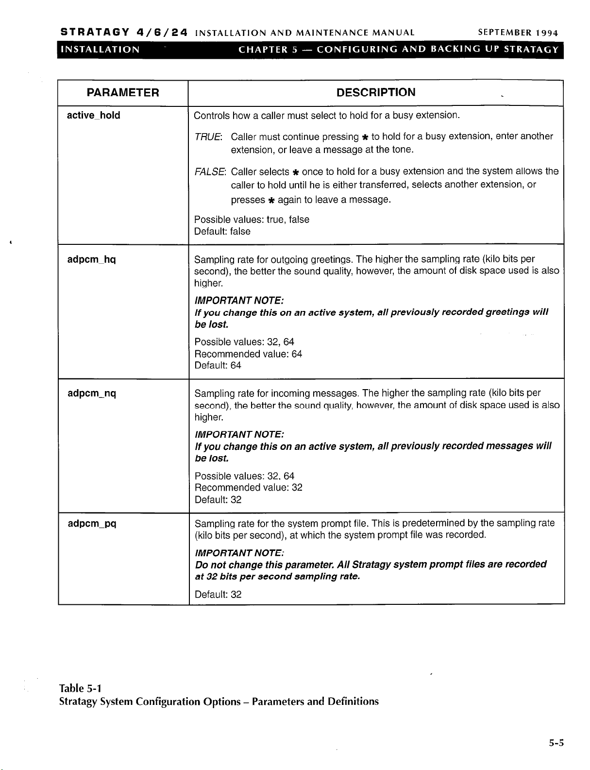
STRATAGY 4/6/24
INSTALLATION AND MAINTENANCE MANUAL SEPTEMBER 1994
PARAMETER
active-hold
adpcm-hq Sampling rate for outgoing greetings. The higher the sampling rate (kilo bits per
Controls how a caller must select to hold for a busy extension.
TRUE Caller must continue pressing * to hold for a busy extension, enter another
extension, or leave a message at the tone.
FALSE Caller selects * once to hold for a busy extension and the system allows the
caller to hold until he is either transferred, selects another extension, or
presses * again to leave a message.
Possible values: true, false
Default: false
second), the better the sound quality, however, the amount of disk space used is also
higher.
IMPORTANT NOTE:
If you change this on an active system, all previously recorded greetings will
be lost.
Possible values: 32, 64
Recommended value: 64
Default: 64
DESCRIPTION
adpcm-nq Sampling rate for incoming messages. The higher the sampling rate (kilo bits per
second), the better the sound quality, however, the amount of disk space used is also
higher.
IMPORTANT NOTE:
If you change this on an active system, all previously recorded messages will
be lost.
Possible values: 32, 64
Recommended value: 32
Default: 32
adpcm-pq
Sampling rate for the system prompt file. This is predetermined by the sampling rate
(kilo bits per second), at which the system prompt file was recorded.
IMPORTANT NOTE:
Do not change this parameter. All Stratagy system prompt files are recorded
at 32 bits per second sampling rate.
Default: 32
Table 5-l
Stratagy System Configuration Options - Parameters and Definitions
5-5

STRATAGY 4/6/24
INSTALLATION AND MAINTENANCE MANUAL
SEPTEMBER 1994
PARAMETER
begin-ret-prompt
Controls whether the system says “Begin recording at the tone, . . . or hang up” before
DESCRIPTION
taking a message. This also affects the “to re-record press 2” and “to append press 3
menu selections during the record menu that is given after a recording.
TRUE: The system plays the above prompt.
FALSE: The system does not play the above prompt. The caller only hears a tone.
Possible values: true, false
Default: true
box-idx
‘
Sets the User ID as the index directory for the specified port. The index directory
is a special mode which allows Stratagy to search its User IDS for a match on the
Directory Name fields.
Example: Define this option as box-idx 411 1 to set User ID 411 as the directory
search ID for port 1.
NOTE:
Stratagy builds an index file based on information given in the Directory Name
fields. It allows you to use one or more letters to perform the search, matching all
entries possible. For every User ID that matches, Stratagy plays the Name and
Extension recording - which really may play any recording you want.
Possible values: valid User ID and valid pot-l
Default: 411
box-snd Sets the User ID as the direct message ID for the specified port. The direct
message ID allows you to record a message for a User ID without having to
execute the Extension field and/or hear the User ID’s greeting. This is particularly
useful for an Operator transferring directly to voice mail.
Possible values: valid User ID and valid port
Default: 998
ca-file File to store incoming SMDR data. The data is read from the logical port defined
by the option ca-pot-t. This is useful for collecting the SMDR output from a switch,
storing it while the system runs, and then during a shutdown having a call
accounting package read, analyze and manipulate the data.
Possible values: valid DOS filename. The single quotes are required.
Default: ‘SMDR.DAT
ca-port Logical pot-t to read SMDR data from while the system is running. The data will be
stored in the file specified by the option ca-file.
Possible values: 0, 1, 2, 3, 4 (port number)
Default: 0
Table 5-l
Stratagy System Configuration Options - Parameters and Definitions (continued)
i
_’
5-6

STRATAGY 4/6/24
INSTALLATION AND MAINTENANCE MANUAL SEPTEMBER 1994
PARAMETER
clock-sync
cmt-maxlen
defaults-box User ID to use for the default values when creating a new User ID. The field
Whether the system tries to re-synchronize the DOS software clock with the PC
hardware clock. It may be useful to turn this off (by setting it to FALSE) if you
have another utility controlling the PC clock.
TRUE Stratagy re-synchronizes the DOS software clock with the PC hardware
clock.
FALSE Stratagy does not re-synchronize the clocks.
Possible values: true, false
Default: true
Number of seconds allowed for recording a List comment.
Possible values: 1 - 99 (seconds)
Default: IO
values in the default User ID are copied into a new User ID upon initialization.
Note:
n Not all fields are copied. Comment, Extension, and Directory Name fiefds’are
initialized separately. If a Security Code is defined, it uses it as the default instead
of using the User ID as the default.
DESCRIPTION
n All Notify and Auto-Schedule records are copied. Therefore, to initialize all new
User IDS with a minimum set of Notify and Auto-Schedule settings, first define
those settings in the “defaults box” 997 (unless you change the default User ID)
before creating new User IDS. This is useful for setting standard, or default,
settings such as message light ON/OFF.
Operates in the same manner as the guest-defaults option.
Possible values: valid User ID
Default: 997
diskwarn Percentage threshold Stratagy uses for causing a Disk Notify to execute. This is a
remaining percentage threshold.
Example: To have Stratagy notify you when the remaining disk space falls below
20%, use a value of 20.
Possible values: 1 - 99
Default: 20
dtmf-dly Time between DTMF tones when Stratagy is dialing. In units of 10 ms.
0: The time is country-dependent (50 ms in the US, 80 ms in the UK). This is
appropriate for almost all cases.
Possible values: 0, 3 - 19 (units of 10 ms)
Default: 0 (country-dependent)
Table 5-1
Stratagy System Configuration Options - Parameters and Definitions (continued)
5-7

STRATAGY 4/6/24
PARAMETER
INSTALLATION AND MAINTENANCE MANUAL
DESCRIPTION
SEPTEMBER 1994
\
/’
dtmf-gate
Before dialing any User ID extension field Stratagy first verifies that DTMF was
entered since the call last accessed the User ID (usually 991) specified in the
DONE Chain of the initial User ID (usually 990). This “gate” prevents the transfer
of a dead/phantom call to the operator on those switches that do not have
disconnect supervision. Stratagy does not perform the “gate” action when the
Extension field begins with @.
TRUE Stratagy “gate’s by requesting the caller to “Say yes at the tone” to
complete the chain and transfer.
FALSE: Do not have Stratagy complete the chain and transfer by requesting the
caller “Say yes at the tone.”
Possible values: true, false
Default: true
dtmf-on
Length of the DTMF tones played by the system. In units of 10 ms.
Example: 20 is .2 set (200 ms).
Possible values: 10, 20, . . . . 90 (units of 10 ms)
Default: 20 (.2 set)
exit-digit Defines one (1) additional DTMF tone that will cause Stratagy to exit/stop during
recordings and present the Recording options.
Possible values: 0 - 9, *, # The single quotes are required.
Default: ‘#’
future-delivery
User ID to use to allow users to specify the time and/or date when a message will
be delivered for the future delivery feature. When the messages are awaiting
future delivery, they are stored in the User ID specified. Therefore, the User ID
cannot be used for any other purpose. The future delivery messages in this User
ID cannot be deleted or listened to. This User ID mailbox cannot be accessed by
a security code.
Possible values: valid User ID
Default: 995
gain-norm Starting volume of the ports.
Possible values: 8, -7, . . . . 0, . . . . 7, 8
Default: 0
Table 5-1
Stratagy System Configuration Options - Parameters and Definitions (continued)
5-8

STRATAGY 4/6/24
INSTALLATION AND MAINTENANCE MANUAL
SEPTEMBER 1994
PARAMETER
guest-defaults
guest-min
DESCRIPTION
User ID to use for the default values when creating a new guest User ID. The field
values in the default guest User ID are copied into a guest User ID upon
initialization. Note:
n Not all fields are copied. Comment, Extension, and Directory Name fields are
initialized separately. If a Security Code is defined, it uses it as the default instead
of using the User ID as the default.
H All Notify and Auto-Schedule records are copied. Therefore, to initialize all new
guest User IDS with a minimum set of Notify and Auto-Schedule settings, first
define those settings in the “defaults box” 997 (unless you change the default Use
ID) before creating new User IDS. This is useful for setting standard, or default,
settings such as message light ON/OFF.
Operates the same way as the defaults-box option.
Possible values: valid User ID
Default: 996
Starting User ID that may be used when creating a Guest User ID. When used in
conjunction with the guest-max option, they limit the number of Guest User IDS
that may be created.
Example: If this value is 90000 then the first guest User ID that is created will have
User ID 90000. The second guest will have User ID 90001, etc.
Possible values: valid User ID
Default: 90000
guest-max
hangup-supervision Whether the switch supports Loop Current Off/Drop for hang up supervision.
Table 5-l
Stratagy System
Configuration Options - Parameters and Definitions (continued)
Last User ID that may be used when creating a Guest User ID. When used in
conjunction with the guest-min option, they limit the number of Guest User IDS
that may be created.
Example: If this value is 90199, then the last guest User ID that may be created is
User ID 90199.
Possible values: valid User ID larger than the guest-min option setting
Default: 90199
TRUE If your switch supports Loop Current Off/Drop for hang up supervision, this
option should be true. Even if your switch does not support this capability, it
usually has NO NEGATIVE EFFECT when set at true.
FALSE If you notice call transfer problems such as disconnects or three-way
conferencing, try setting this to false. If the problems are not solved by
setting this to false, set it back to true.
Possible values: true, false
Default: true
,
5-9

STRATAGY 4/6/24
INSTALLATION AND MAINTENANCE MANUAL
SEPTEMBER 1994
PARAMETER
hot-box
If you remove the initial # sign and activate this option, when Stratagy detects a
DESCRIPTION
specific tone, Stratagy “jumps” to a specified User ID. Used to handle incoming
faxes, detect connections from TDD machines for deaf communication, etc.
There are 24 values available. For example:
set hot-box 994
set hot-box 994 1
sets all 24 to User ID 994
sets the first hot-box to User ID 994
Possible values: valid User ID, possibly followed by a hot-box value (1 - 24)
Stratagy 24 Default: comment line (# set hot-box 994)
Stratagy 4 and 6 default: 994
‘
lognam System log file name. This log file contains start-up information, any execution
error information, system actions, and shutdown information.
NOTE:
This file keeps grows slowly It is a good idea to periodically archive or delete it
once or twice a year, whenever you perform preventive maintenance.
Possible values: valid DOS filename
The single quotes are required.
Default: ‘Stratagy.LOG’
Ipt-port Printer port Stratagy should use when asked to print a report.
Possible values: 0 (no printer), 1, 2 (port number)
Default: 1
max-dl-inits
Number of simultaneous ports that may go off-hook and dial the telephone
system initialization code. This is necessary because some switches are blocking.
Possible values: 1, 2, . . . . number of ports
Default: 2
max-prompt Number of times a prompt should repeat until deciding to hang up.
Possible values: 1 - 9
Default: 2
msg-log
By removing the initial # sign on this option and defining a valid DOS file name,
Stratagy will log every received message and every User ID that checks for
messages along with the DTMF entered.
Possible values: valid DOS file name. The single quotes are required.
Default: comment line (#set msg-log ‘MSG.LOG’)
Table 5-l
Stratagy System Configuration Options - Parameters and Definitions (continued)
5-10

STRATAGY 4/6/24
INSTALLATION AND MAINTENANCE MANUAL SEPTEMBER 1994
PARAMETER
n-ochan
Number of dedicated ports (starting at port 1) to reserve for outbound notify ports.
DESCRIPTION
This number must not exceed the total number of available ports.
IMPORTANT NOTE:
If the value is set to 0, Stratagy will attempt to use the highest numbered
IDLE port. The danger of this is that Stratagy may inadvertently begin a
notification on a port with an incoming call.
Possible values: 0 - 24 (number of ports)
Default: 0
‘
iam-maxlen Maximum number of seconds to allow for recording a User ID’s name and
extension. The name and extension recording is used for directory access and
whenever Stratagy tries to identify the User ID.
Possible values: 1 - 99 (seconds)
Default: 5
lew-send Whether a User ID (User) can send a message to a list of User IDS that is created
when the destination is defined.
TRUE: Allow a User ID (User) to send a message to a list of User IDS that is created
when the destination is defined. When User presses 4 to send a new
message, then 1 to select a User ID destination, the User is prompted to
enter the next User ID or the # sign to finish entering User IDS. When the
User presses 3 to send, the message is sent to every User ID that was
entered.
FALSE: Do not allow a User ID (User) to send a message to a list of User IDS that is
created when the destination is defined.
Possible values: true, false
Default: false
notify-restriction
If you remove the initial # sign and activate this option with a valid port number,
Stratagy restricts notify to use only the defined port. The port will still take
incoming calls. This is particularly useful for those switches that require message
lights to be turned off by the same port that turned them on.
Possible values: 1, 2, . . . . highest port number
Default: comment line (# set notify-restriction 1)
password
Sets the system password. The password is case sensitive; i.e., uppercase letters
are different from lowercase letters.
Possible values: up to 8 alphabetical characters. The single quotes are required.
Default: ‘Stratagy’
Table 5-1
Stratagy System Configuration Options - Parameters and Definitions (continued)
5-11

STRATAGY 4/6/24
INSTALLATION AND MAINTENANCE MANUAL
SEPTEMBER 1994
PARAMETER
play-skip
Number of seconds to rewind or skip forward during message playback when a *
DESCRIPTION
or # is pressed.
Possible values: 1 - 99 (seconds)
Default: 5
please-hold Whether or not the system says “Please hold while I try that extension for you”
before transferring a caller.
TRUE The system plays the above prompt.
FALSE The system does not play the above prompt and immediately executes the
‘
dl_dtwait string or the Extension string, as appropriate.
Possible values: true, false
Default: true
prompt-file
Default prompt file that Stratagy should use on an incoming call. This allows you
to redefine the default language prompt file from English. It does not preclude you
from changing the prompt file during the call.
Possible values: valid prompt file. The single quotes are required.
Default: ‘English’
purge
Number of days before a message is set for purging/deletion. Whenever a User
accesses his User ID and presses 1 to Play Messages, the system will tell him
how many messages he has that will be automatically deleted when he presses 9
to return to the previous menu.
IMPORTANT NOTE:
Once a message is deleted by purging there is no way to retrieve it.
Possible values: 0 (purging disabled), 1 - 99 (days)
Default: 0
rotary Whether rotary detection is enabled.
With rotary detection enabled, the system detects and understands rotary entered
digits. Note the following:
n Only rotary digits 3 and higher are currently detected. Therefore, if you plan to USC
this feature, make sure that all your outside dialing User IDS do not have either
digits 1 or 2.
n There are no * and # signs on rotary phones. Therefore, setting this to true will
introduce additional delays when the system detects the dialed number.
Possible values: true (enabled), false (disabled)
Default: false
Table 5-l
Stratagy System Configuration Options - Parameters and Definitions (continued)
5-12

STRATAGY 4/6/24
INSTALLATION AND MAINTENANCE MANUAL
SEPTEMBER 1994
PARAMETER
security-min-length
short-direct-send What is played when the direct message code (usually 998) is entered followed
shutdown Day and time Stratagy performs automatic shutdown for disk maintenance.
Minimum length security code that Stratagy will accept as a new security code
when a user attempts to change it from a telephone.
Possible values: 1 - 8
Default: 1
by the User ID.
TRUE: “You entered” and the User ID’s name and extension recording plays.
FALSE User ID’s current greeting plays (as if received a Ring No Answer).
Possible values:
Default: false
The first value between the single quotes is the day of week, where
0 Sunday
1 Monday
2 Tuesday
3 Wednesday
true,
false
DESCRIPTION
4 Thursday
5 Friday
6 Saturday
-1 everyday
The second value
shutdown occurs, this is given in 24 hour format with the colon (:) omitted. For
example, 9:30 p.m. is 2130.
Default: ‘2 130’ (Tuesday at 1:30 a.m.)
tape-length
timestamp-forwards Controls the date/time stamp the system uses on a forwarded message.
When a User selects option 1, and then 78 (continuous play) or 79 (continuous
delete), this option defines the total number of minutes to play or delete. Usually
defines the length of one side of a tape that might be used for recording a set of
messages in a User ID.
Possible values: 10 - 99 (minutes)
Default: 30
TRUE Use the date/time that the message was forwarded.
FALSE Use the original date and time the message was first recorded.
Possible values: true, false
Default: true
between
the single quotes is the hour and minute at which the
Table 5-l
Stratagy System Configuration Options - Parameters and Definitions (continued)
,
5-l 3

STRATAGY 4/6/24
INSTALLATION AND MAINTENANCE MANUAL
SEPTEMBER 1994
PARAMETER
tmo-blank
tmo-dtmf Amount of time Stratagy waits to determine that the caller has finished entering
,
tmo-hold Number of seconds before Stratagy attempts to transfer a caller after the caller
Total number of minutes Stratagy waits before blanking the Main Menu screen to
prevent screen burn-in.
NOTE:
This option only blanks the screen if the current screen is the Main Menu.
Possible values: 0 (disabled), 1 - 99 (minutes)
Default: 5
DTMF digits (provided that they do not press the #). In units of 100 ms.
Possible values: 10 - 99 (units of 100 ms)
Default: 12
has pressed * to hold for a busy extension.
When a caller presses * to hold for a busy extension, Stratagy plays a file called
C:\Stratagy\HOLD.VOX after which Stratagy attempts to transfer the caller again.
If that file is missing, Stratagy is silent for the number of seconds specified by this
option.
NOTE:
To have callers hear a specialty recording while on hold, record over HOLD. VOX
by accessing the System Administration Menu. See the Programming section,
Chapter 5, “System Administrator’s User ID” for details.
DESCRIPTION
Default: 20 (seconds)
tmo-idle When this value is greater than 0, it enables a special function in Stratagy to go
off-hook and back on-hook whenever a port is idle for the specified number of
seconds. This is necessary only under rare circumstances when a telephone
switch may not release a station that is connected to Stratagy even after Stratagy
has gone on-hook.
Default: 0
tmo-menu Amount of time Stratagy waits before repeating a choice menu. In units of 100
ms.
Possible values: 1
Default: 20
tmo-pickup Minimum amount of time the system waits between an on-hook and off-hook
event. In units of 100 ms.
Possible values: 10 - 99 (units of 100 ms)
Default: 20
Table 5-1
Stratagy System Configuration Options - Parameters and Definitions (continued)
- 99 (units of 100 ms)
5-14

STRATAGY 4/6/24
INSTALLATION AND MAINTENANCE MANUAL
SEPTEMBER 1994
PARAMETER
tmo-serial
tmo-silence
,
tmo-sound Maximum amount of sound/dial tone time the system waits before deciding to
user-log If you remove the initial # sign and activate this option, whenever a User ID is
Maximum number of seconds Stratagy waits for a response when communicating
with other peripheral devices through a serial port. Otherwise, Stratagy could
potentially wait forever.
Possible values: 2 - 99 (seconds)
Default: 2
Maximum amount of silence time the system waits before deciding to finish a
recording and hang up. In seconds.
Possible values: 3 - 9 (seconds)
Default: 5
finish a recording and hang up. In seconds.
Possible values: 3 - 9 (seconds)
Default: 5
accessed via DTMF, the system will make an entry in the log file specified. The.
log entry consists of the date, time and User ID. This is useful for creating a data
file which can later be analyzed for call distributions and accesses by dates, days,
and times.
Possible values: valid DOS file name. The single quotes are required.
Default: comment line (# set user-log ‘USERID.LOG’)
DESCRIPTION
Stratagy 6 and 24 only.
baud1 Baud rate for logical serial port 1. This operates on the physical COM port as
defined by set serial-port1 .
Possible values: 300, 1200, 2400, 9600.
Default: 2400
baud2 Baud rate for logical serial port 2. This operates on the physical COM port as
defined by set serial-port2.
Possible values: 300, 1200, 2400, 9600.
Default: 2400
baud3 Baud rate for logical serial port 3. This operates on the physical COM port as
defined by set serial-port3.
Possible values: 300, 1200, 2400, 9600.
Default: 2400
baud4 Baud rate for logical serial port 4. This operates on the physical COM port as
defined by set serial-port4.
Possible values: 300, 1200, 2400, 9600.
Default: 2400
Table 5-I
Stratagy System Configuration Options -
Parameters and Definitions (continued)
Stratagy 6 and 24 only.
Stratagy 6 and 24 only.
Stratagy 6 and 24 only.
Stratagy 6 and 24 only.
5-15

STRATAGY 4/6,‘24
INSTALLATION AND MAINTENANCE MANUAL
SEPTEMBER 1994
PARAMETER
databitsl
databits
databits
databits
parity1
DESCRIPTION
Number of data bits for logical serial port 1.
Possible values: 7, 8
Default: 8
Number of data bits for logical serial port 2.
Possible values: 7, 8
Default: 8
Number of data bits for logical serial pot-l 3.
Possible values: 7, 8
Default: 8
Number of data bits for logical serial port 4.
Possible values: 7, 8
Default: 8
Parity to use for logical serial port 1.
Possible values: none, even, odd, mark, space
Default: none
Stratagy 6 and 24 only.
Stratagy 6 and 24 only.
Stratagy 6 and 24 only.
Stratagy 6 and 24 only.
Stratagy 6 and 24 only.
parity2
parity3
parity4
Parity to use for logical serial port 2.
Possible values: none, even, odd, mark, space
Default: none
Parity to use for logical serial pot-t 3.
Possible values: none, even, odd, mark, space
Default: none
Parity to use for logical serial port 4.
Possible values: none, even, odd, mark, space
Default: none
Stratagy 6 and 24 only.
Stratagy 6 and 24 only.
Stratagy 6 and 24 only.
Table 5-I
Stratagy System Configuration Options - Parameters and Definitions (continued)
5-16
,’

STRATAGY 4/6/24
INSTALLATION AND MAINTENANCE MANUAL SEPTEMBER 1994
PARAMETER
serial-port1
serial-port2
DESCRIPTION
In order for Stratagy to communicate with peripheral devices connected to
COM/RS232 ports, it needs to know which ports are connected. There is a
mapping from the port that Stratagy knows to the physical port on the computer.
This mapping is defined by this option. To define serial port 1 as active, simply
define the COM port where it should be mapped.
Example: Set this option to 1 to connect serial port 1 (Stratagy) to COM port 1.
Possible values: 0 (not connected), 1 (COM port I), 2 (COM port 2), 3 (COM port
3), 4 (COM port 4)
Default: 0
In order for Stratagy to communicate with peripheral devices connected to
COMRS232 ports, it needs to know which ports are connected. There is a
mapping from the port that Stratagy knows to the physical port on the computer.
This mapping is defined by this option. To define serial port 2 as active, simply
define the COM port where it should be mapped.
Example: Set this option to 2 to connect serial port 2 (Stratagy) to COM port 2.
Possible values: 0 (not connected), 1 (COM port I), 2 (COM port 2) 3 (COM port
3), 4 (COM port 4)
Default: 0
Stratagy 6 and 24 only.
Stratagy 6 and 24 only.
serial-port3
serial-port4
In order for Stratagy to communicate with peripheral devices connected to
COM/RS232 ports, it needs to know which ports are connected. There is a
mapping from the port that Stratagy knows to the physical port on the computer.
This mapping is defined by this option. To define serial port 3 as active, simply
define the COM port where it should be mapped.
Example: Set this option to 3 to connect serial port 3 (Stratagy) to COM port 3.
Possible values: 0 (not connected), 1 (COM port I), 2 (COM port 2), 3 (COM port
3), 4 (COM port 4)
Default: 0
In order for Stratagy to communicate with peripheral devices connected to
COM/RS232 ports, it needs to know which ports are connected. There is a
mapping from the port that Stratagy knows to the physical port on the computer.
This mapping is defined by this option. To define serial port 4 as active, simply
define the COM port where it should be mapped.
Example: Set this option to 4 to connect serial port 4 (Stratagy) to COM port 4.
Possible values: 0 (not connected), 1 (COM port l), 2 (COM port 2), 3 (COM port
3), 4 (COM port 4)
Default: 0
Stratagy 6 and 24 only.
Stratagy 6 and 24 only.
Table 5-1
Stratagy System Configuration Options - Parameters and Definitions (continued)
5-l 7

STRATAGY 4/6/24
INSTALLATION AND MAINTENANCE MANUAL
SEPTEMBER 1994
PARAMETER
stopbitsl
stopbits
stopbits
,
stopbits
fax-dl-init
Number of stop bits to use for logical serial port 1.
Possible values: 0, 1, 2
Default: 1
Number of stop bits to use for logical serial port 2.
Possible values: 0, 1, 2
Default: 1
Number of stop bits to use for logical serial port 3.
Possible values: 0, 1, 2
Default: 1
Number of stop bits to use for logical serial port 4.
Possible values: 0, 1, 2
Default: 1
Dial codes Stratagy dials when a user dials 7 2 to send a fax message he has
received to a fax machine for pick up. Generally, this is the code for accessing a
public network line, i. e., “9”.
DESCRIPTION
Stratagy 6 and 24 only.
Stratagy 6 and 24 only.
Stratagy 6 and 24 only.
Stratagy 6 and 24 only.
fax-flow-control
fax-id
fax-max-retries
Typical value: dial code to access an outside line. The single quotes are required.
Default: ‘9,’ (dial 9 and pause for 2 set)
Class 2 command to set the type of flow control for the fax/modem.
‘& K3’
‘IQ3 X3 &K3’ Aceex fax/modem
‘X3 &K3’ Practical Peripherals fax/modem
Possible values: Include ’ ‘, ‘ ‘.
Default: ‘&K3’
Fax/modem ID or telephone number used for identification to other fax devices.
Single quotes are required.
Default: ‘ ‘ (no identification)
Maximum number of times, after the first, to retry sending a fax if it is
unsuccessful. Used only when sending the fax in two-call mode; i.e., the caller
enters a fax telephone number that the fax/modem calls and then sends the fax.
Possible values: 0 - 9 (retries)
Default: 1
Zoom fax/modem
The single quotes are required.
Stratagy 24 only.
Stratagy 24 only.
Stratagy 24 only.
Stratagy 24 only.
Table 5-1
Stratagy System Configuration Options - Parameters and Definitions (continued)
5-18

STRATAGY 4/6/24
INSTALLATION AND MAINTENANCE MANUAL
SEPTEMBER 1994
PARAMETER
fax-receive-reverse
fax-receive-speed
,
fax-requeue-interval
Setting depends solely on the Class 2 fax/modem used. Controls whether to
reverse the fax databits on receive.
TRUE Setting for most fax/modems.
FALSE Setting for some fax/modems. If the faxes received are reverse (mirror
images) from the original, try setting this option to FALSE.
Possible values: true, false
Default: true
Maximum speed Stratagy allows for receiving faxes. Set this appropriately
depending upon the type and speed of your computer. Normally a value of 3
works for 386 CPUs at 33 MHz or higher. If you experience data loss on your
faxes, lower this setting.
‘: (empty string) as fast as possible
‘0’: 2400
‘I’: 4800
‘3’: 9600
Possible values: “, ‘0’, ‘I’, ‘3’
Default: ‘1’
Number of minutes to wait between retries for fax-max-retries.
DESCRIPTION
Stratagy 24 only.
The single quotes are required.
Stratagy 24 only.
fax-reset
fax-send-reverse
Possible values: 1 - 99 (minutes)
Default: 5
Reset command to send to the fax/modem when DTR is dropped. Use W3’for
most fax/modems. Single quotes are required.
Default: ‘&D3’
Setting depends solely on the Class 2 fax/modem used.
FALSE Setting for most fax/modems.
TRUE Setting for some fax/modems. If the faxes received are reverse (mirror
images) from the original, try setting this option to TRUE.
Possible values: true, false
Default: false
Stratagy 24 only.
Stratagy 24 only.
Stratagy 24 only.
,
Table 5-l
Stratagy System Configuration Options - Parameters and Definitions (continued)
5-19

STRATAGY 4/6/24
INSTALLATION AND MAINTENANCE MANUAL
SEPTEMBER 1994
PARAMETER
fax-send-speed
,
fax-start-char
fax1
Maximum speed that Stratagy will use for sending faxes. Depending upon the
type and speed of your computer set this appropriately. Normally a value of 3
works for 386 CPUs at 33 MHz or higher. If you experience data loss on your
faxes, lower this setting.
‘: (empty string) as fast as possible
‘0’: 2400
‘1’: 4800
‘3’: 9600
Possible values: “, ‘O’, ‘I’, ‘3’
Default: ‘1’
Whether the fax/modem sends a control start character.
FALSE Setting for most fax/modems, including Zoom.
TRUE: Setting for some fax/modems, including Accex and Practical Peripherals.
Possible values: true, false
Default: true
Station, or extension, number connected to the first fax/modem.
Example: If the first fax/modem is connected to extension 101, use the value ‘101’.
The single quotes are required.
DESCRIPTION
The single quotes are required.
Stratagy 24 only.
Stratagy 24 only.
fax2
smdi-base-port
smdi-port
Default: ‘ ’ (no station or extension number)
Station, or extension, number connected to the second fax/modem.
Example: If the second fax/modem is connected to extension 102, use the value
‘102’. The single quotes are required.
Default: ‘ ‘ (no station or extension number)
Some SMDI installations use logical terminal numbers that do not begin with 1
(for example if it instead uses the extension, or physical number to define the
terminal). In these situations, you must define the extension number where port 1
is connected. The system assumes that the extension numbers are then
connected in numerical order to the remaining ports.
Default: 1
Logical serial port Stratagy uses for SMDI integration.
Possible values: 0 (disables SMDI integration), 1, 2 (port number)
Default: 0
Stratagy 24 only.
Stratagy 24 only.
Stratagy 6 and 24 only.
Stratagy 6 and 24 only.
Table 5-1
Stratagy System Configuration Options - Parameters and Definitions (continued)
5-20

STRATAGY 4/6/24
INSTALLATION AND MAINTENANCE MANUAL SEPTEMBER 1994
PARAMETER
smdi-pretimeout
smdi-type
box-grt
DESCRIPTION
Maximum number of seconds that an SMDI packet can PRECEED the forwarded
call.
Possible values: 5 - 20 (seconds)
Default: 50
Protocol Stratagy uses when using RS-232 data integration (outband integration).
‘smdi’: standard SMDI integration
‘s75’: System 75 integration
Possible values: ‘SMDI’, ‘~75’ The single quotes are required.
Default: ‘smdi’ Stratagy 6 and 24 only.
Sets the starting User ID for the port given as the last value.
Example: box-grt 990 1 means that on port 1, a new call starts at User ID 990.
Possible values: valid User ID and valid pot-t
Defaults: 990 1
990 2
Stratagy 6 and 24 only.
.I
990 24
n-rings Number of rings to wait before answering per pot-t. This is useful for those
telephone systems that do not allow incoming lines to ring in a station hunt group,
or do not provide delayed ringing. Also, it may be used to setup backup
answering for a secondary attendant operation.
NOTE:
There is a side effect. When a user wants to pickup his messages, he must wait
the specified number of rings before Stratagy answers.
Example: To have pot-t 1 answer on the second ring, use set n-rings 2 1.
Possible values: 1 - 9 (number of rings); valid port number
Defaults: 1 1
12
; 24
Table 5-1
Stratagy System Configuration Options -
,
Parameters and Definitions (continued)
5-21
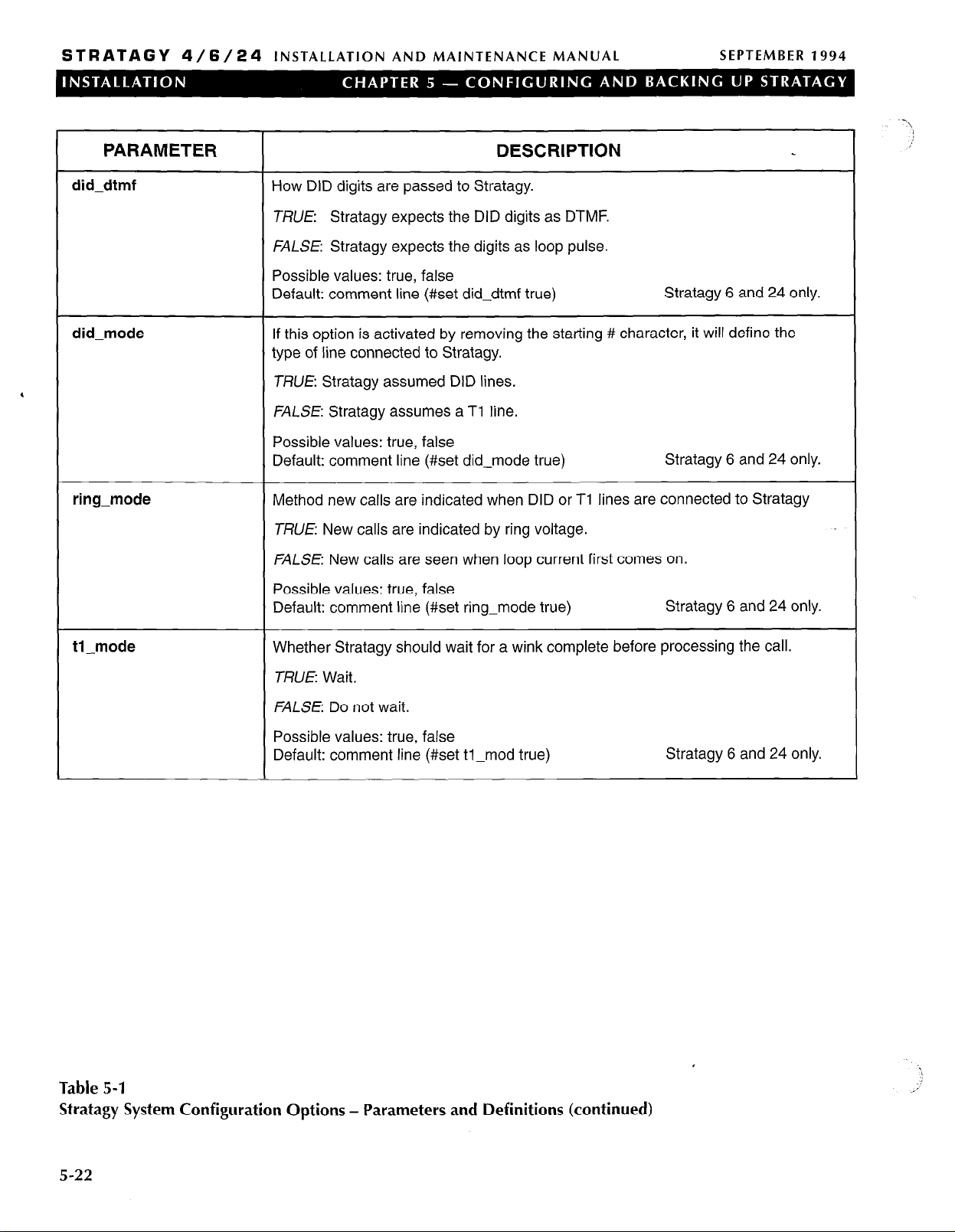
STRATAGY 4/6/24
INSTALLATION AND MAINTENANCE MANUAL
SEPTEMBER 1994
PARAMETER
did-dtmf
How DID digits are passed to Stratagy.
DESCRIPTION
TRUE: Stratagy expects the DID digits as DTMF.
FALSE: Stratagy expects the digits as loop pulse.
Possible values: true, false
Stratagy 6 and 24 only.
did-mode
Default: comment line (#set did-dtmf true)
If this option is activated by removing the starting # character, it will define the
type of line connected to Stratagy.
‘
TRUE: Stratagy assumed DID lines.
FALSE: Stratagy assumes a Tl line.
Possible values: true, false
Stratagy 6 and 24 only.
ring-mode
Default: comment line (#set did-mode true)
Method new calls are indicated when DID or Tl lines are connected to Stratagy
TRUE New calls are indicated by ring voltage.
FALSE: New calls are seen when loop current first comes on.
Possible values: true, false
Default: comment line (#set ring-mode true)
Stratagy 6 and 24 only.
H-mode
Whether Stratagy should wait for a wink complete before processing the call.
TRUE: Wait.
FALSE: Do not wait.
Possible values: true, false
Default: comment line (#set tl-mod true)
Table 5-l
Stratagy System Configuration Options - Parameters and Definitions (continued)
Stratagy 6 and 24 only.
5-22

STRATAGY 4/6/24
INSTALLATION AND MAINTENANCE MANUAL SEPTEMBER 1994
5 INSTALL FROM A: DRIVE
Use this function to install Stratagy software from
diskettes using the Stratagy floppy A: drive. This is
required when upgrading a Stratagy 4 system to a
Stratagy 6 system. It may also be necessary to re-install
Stratagy System or Prompt software from floppy
diskettes.
IMPORTANT NOTE:
Before installing or re-installing Stratagy
System software, ensure you have a current
backup of system data. We recommend that
you use the Stratagy Backup initially and
periodically to preserve system data.
From the Stratagy Configuration Utility Menu, press 3 or
use the arrow keys (7‘ L ) to highlight 3.
from A:
Stratagy prompts:
Inset-t the first disk in the floppy drive, and press any
key.. .
Insert the first diskette. Follow the directions. When
complete, the Stratagy Configuration Utility Menu
displays.
Drive
and press
Enter.
Install
6 TOSHIBA PLUG AND PLAY
Use this function to change the Stratagy system to a
different Toshiba Plug and Play capability than what has
been pre-installed as a factory setting. Each Stratagy
system has been pre-installed at the factory for out-ofbox (Plug and Play) operation on a specific Toshiba
telephone system as follows:
H Stratagy 4 with Strata DK8
1 Stratagy 6 with Strata DK16
greeting that says “Thank you for calling” and User ID
991 says “To reach the party.. . dial the extension.. .”
All calls into a Stratagy system with Toshiba Plug and
Play will hear the above greetings and transfer to the dial
Strata DK station. If the Strata DK station (extension
number) is busy or does not answer, Stratagy will
automatically play a greeting that says “User ID XXX
(Strata DK dialed station number) is not available or
busy,” then prompt the caller to leave a message, etc.
This is the out-of-box, Toshiba Plug and Play operation
for all Stratagy systems.
IMPORTANT NOTE:
If you are modifying an existing Stratagy
system, selecting this function changes all
the settings to the new Toshiba telephone
system default values, and deletes the User
ID (mailbox) customizations and installs the
Strata default mailboxes.
NOTE:
We recommend that you use the Stratagy
Backup Utility initially and periodically to
preserve system data. Before making changes to
this selection, ensure you have a current backup.
From the Stratagy Configuration Utility Menu, press 4 or
use the arrow keys ( t J, ) to highlight 4
Plug and Play
See Figure 5-4 for the Toshiba Plug and Play options. To
select an option, use the arrow keys ( 7‘ J, ) to
highlight the option and press
Toshiba Plug and Play
and press
Enter.
Enter.
1. STRATA DK 8
2. STRATA DK 16
3. STRATA DK 280A
. Toshiba
n Stratagy 24 with Strata DK280A
All dial codes, tone patterns, and integration patterns
specific to the above system have been pre-installed at
the factory for each Stratagy system.
IMPORTANT NOTE:
The above Strata DK must be configured for
the appropriate voice mail system settings
individually. See the specific Strata DK
Installation and Maintenance manual for
these procedures.
In addition, with Toshiba Plug and Play, the Strata DK
default station (extension number) User ID mailboxes
have also been pre-installed for the specific Stratagy and
Strata DK systems described above.
Stratagy User ID 990 also contains a pre-installed
Figure 5-4
Toshiba Plug and Play Screen
Once you select an option, the Stratagy utility
automatically defines the telephone system dial codes,
telephone system tone patterns, and system integration
patterns for the specific phone system. The Stratagy
Configuration Utility Menu then displays. The Toshiba
telephone system is complete and the selected system
displays in the Main Menu. No other Stratagy steps are
necessary.
We recommend that you back up the current database at
this time by selecting the Stratagy Backup Utility.
5-23

STRATAGY 4/6/24
INSTALLATION AND MAINTENANCE MANUAL
SEPTEMBER 1994
Otherwise, press
return to the Main Menu for call processing or Stratagy
programming.
Esc
again to reboot Stratagy and
7 TOSHIBA SWITCH
INTEGRATION
Use this function to change the Toshiba Plug and Play
capability that has been pre-installed with each Stratagy
system (see “Toshiba Plug and Play”). Selecting an
option automatically defines the Toshiba telephone
system dial codes, Toshiba telephone system tone
patterns, and Toshiba system integration patterns for the
‘
specific Toshiba telephone system. No other Stratagy
system steps are necessary.
If you are modifying an existing Stratagy system,
selecting this function changes all the settings to the new
Toshiba telephone system values. The User ID
(mailboxes) customizations are not deleted or changed.
NOTE:
We recommend fhaf you use the Sfrafagy
Backup Utility initially and periodically to
preserve system data. Before making changes to
this selection, ensure you have a current backup.
From the Stratagy Configuration Utility Menu, press 5 or .‘;
use the arrow keys ( 1‘ J, ) to hjghlight
5. Toshiba Switch Integrationand
press
Enter.
See Figure 5-5 for the Toshiba Switch Integration
options. To select an option, use the arrow keys
( 1‘ J, ) to highlight the option and press
Once you select an option, the Stratagy utility
automatically defines the Toshiba telephone system dial
codes, Toshiba telephone system tone patterns, and
Toshiba system integration patterns for the specific
phone system. The Stratagy Configuration Utility Menu
then displays. Toshiba telephone system integration is
complete and the selected system displays in the Main
Menu. No other Stratagy system steps are necessary.
We recommend that you back up the current database at
this time by selecting the Stratagy Backup Utility.
Otherwise, press
return to the Main Menu for call processing or Stratagy
programming.
Esc
again to reboot Stratagy and
Enter.
# Name: Strata DK 8/16/24/56/96
# Name: Strata DK 280
# Name:
# Name: Perception e/ex
# Name: Perception 4000
# Name:
Strata DK 280 with M-232 Integration
Strata e Vie, XIIe, XXe, Se
5. Toshiba Switch Integration
2001
2002
2006
2003
2004
2005

STRATAGY 4/6/24
INSTALLATION AND MAINTENANCE MANUAL SEPTEMBER 1994
8 OTHER SWITCH
INTEGRATIONS
Use this function to initially configure or modify the
following for non-Toshiba telephone systems:
n Telephone system dial codes
n Telephone system tone patterns
n System integration patterns
IMPORTANT NOTE:
Be sure to configure the Strafagy system in
the above-listed order.
NOTE:
We recommend that you use the Stratagy
Backup Utility initially and periodically to
preserve system data. Before making changes to
this selection, ensure you have a current backup.
From the Stratagy Configuration Utility Menu, press 6
or use the arrow
highlight 6.
Integrations
The Other Switch Integrations Menu (Figure 5-6)
displays. To select an option, press the option number
or
use the arrow keys ( 1‘ L ) to
highlight the option and press
Other Switch Integrations
1. Telephone System Dial Codes
2. Telephone System Tone Patterns
3. System Integration Patterns
Figure 5-6
Other Switch Integrations Menu
When you have finished defining the codes and patterns,
press
Esc
to exit the Other Switch Integrations Menu
and return to the Stratagy Configuration Utility.
We recommend that you back up the current database at
this time by selecting the Stratagy Backup Utility.
Otherwise, press
return to the Main Menu for call processing or Stratagy
programming.
and press
Esc
keys ( 1‘ .L ) to
Other
Switch
Enter.
Enter.
again to reboot Stratagy and
8.1 DEFINING TELEPHONE SYSTEM DIAL
CODES
Stratagy controls certain actions on your telephone
system, or the definition of your telephone system dial
codes. With this option, Stratagy “learns” the dial codes
of your telephone system. See Figure 5-7 for a sample
Telephone System Dial Codes Screen. For a listing of the
dial code parameters and their definitions, see Table 5-2.
8.1 .I SELECTING DEFAULT DIAL CODES
To access Stratagy’s predefined telephone system dial
codes, press
Screen. These closely (if not exactly) match the
telephone system you are using. For a sample Load
Telephone System Dial Codes Screen, see Figure 5-8.
NOTE:
Select a default dial code only for non-Toshiba
telephone systems and only during initial
configuration.
To load a default setting, use the arrow keys ( 1‘
highlight your selection and press
Toshiba telephone system selected will not appear on the
Stratagy system Main Menu. It will be blank unless
modified in the next step.
To cancel this operation without selecting any default dial
codes, press
8.1.2 MODIFYING THE DIAL CODES
If the telephone system you desire does not appear when
Fl
is used from the telephone system dial codes screen
or further modifications to the dial codes are needed,
proceed as follows. To modify a telephone system dial
code:
1.
Use the arrow keys
PgDn,
Fl
from the Telephone System Dial Codes
4. ) to
Enter.
The non-
Est.
( 7‘ L ),
to highlight the dial code parameter. Press
or
PgUp
and
Enter.
2.
Modify the dial code using the line editor at the top
of the screen.
Press
3.
without keeping any changes, press
8.1.3
When you have finished defining the Telephone System
Dial Codes, press
Integrations Menu.
Enter
EXITING THE TELEPHONE SYSTEM DIAL CODES
SCREEN
to save your changes. To escape
Est.
Esc
to return to the Other Switch
5-25

STRATAGY 4/6/24
INSTALLATION AND MAINTENANCE MANUAL
1. Telephone System Dial Codes
SEPTEMBER 1994
# Dial code to put a caller on transfer hold
# Dial code to use when there is no transfer dialtone: F-
# Dial code to return to caller after Ring No Answer : F-
# Dial code to return to caller when there is a Busy : F# Dial code to use after a call screening reject
# Dial code to connect the caller to the extension
# Number of seconds to wait for dialtone detection
# Number of l/100 seconds to use for Flash time
# which DTMF tone to listen to for answer detection :a
# which DTMF tone to listen to for hangup detection
# What to dial BEFORE dialing the User ID extension :
# What to dial AFTER dialing the User ID extension
# What to dial when the system first starts up
‘
# what to dial when the system performs a shutdown :
# what to dial when a port goes off-hook
# Switch name to display on MAIN screen
Figure 5-7
Sample Telephone System Dial Codes Screen
: F-
: F:H
:4
: 55
:d
: 1
:
:
: 'STRATA DK 280'
Fl - Load Telephone System Dial Codes
# Name: Alcatel DCD 601
# Name: Alcatel STK Digitmat 2000
# Name: AT&T 1AESS (analog), 5ESS (digital) CO
# Name: AT&T Merlin II
# Name: AT&T Merlin Legend
# Name: AT&T Partner/Partner+
# Name: AT&T System 25
# Name: AT&T System 75 and Definity
# Name: Centrex
# Name: Comdial 1410/2264
# Name: Contel Executone
# Name: EGL-ONE
# Name: Ericsson BCSl50
# Name: Ericsson MD110
# Name: Ericsson MINC
# Name: Ericsson Information Systems Prodigy
# Name: Fujitsu Focus 100
# Name: Fujitsu Focus 960 PBX
# Name: Fujitsu F-9600 PBX
# Name: Fujitsu 1123
# Name: ISOETEC EZ-1 36/66/96
# Name:
Figure 5-8
Sample Load Telephone System Dial Codes Screen
ISOTEC 108/228
1031
1034
1035
1005
1016
1017
1037
1038
1039
1040
1042
1043
1044
1045
1046
1047
1048
1049
1050
1051
1053
1054
I
5-26

STRATAGY 4/6/24
INSTALLATION AND MAINTENANCE MANUAL SEPTEMBER 1994
PARAMETER
# DIAL CODE TO PUT A CALLER ON TRANSFER HOLD:
Before Stratagy attempts to transfer a caller to an extension, the code Stratagy sends the telephone
system to put the current call on “transfer hold” and send the transfer (or intercom) dial tone.
Typical value: F- (flash-hook)
# DIAL CODE TO USE WHEN THERE IS NO TRANSFER DIALTONE:
If Stratagy is configured to verify that transfer dial tone exists before attempting to transfer a call to the
requested extension, the code Stratagy dials to return to the caller if transfer dial tone is not available. If
this occurs, Stratagy will treat the attempted transfer the same as if the attempted extension were BUSY.
Typical value: F- (flash-hook)
# DIAL CODE TO RETURN TO CALLER AFTER RING NO ANSWER:
During supervised call transfers, the code Stratagy dials to request the telephone switch to reconnect the
caller to Stratagy if the attempted extension rings and does not answer within the specified number of
rings (which is configurable per User ID).
Typical value: F- (flash-hook)
# DIAL CODE TO RETURN TO CALLER WHEN THERE IS A BUSY:
During supervised call transfers, the code Stratagy dials to request the telephone switch to reconnect the
caller to Stratagy if the attempted extension is busy.
Typical value: F- (flash-hook)
DESCRIPTION
# DIAL CODE TO USE AFTER A CALL SCREENING REJECT:
During supervised call transfers, with Call Screening ON, if the extension called rejects the caller, the
code Stratagy dials to reconnect to the caller and play the User ID’s current greeting.
Typical value: F- (flash-hook)
# DIAL CODE TO CONNECT THE CALLER TO THE EXTENSION:
Dial code Stratagy dials during supervised call transfers to complete the call transfer either after detecting
an answer at the called extension, or if Call Screening is ON, after the extension called accepts the call.
Typical value: H (Hang Up)
# NUMBER OF SECONDS TO WAIT FOR DIALTONE DETECTION:
If your telephone system has a limited number of DTMF receivers, or intercom paths for call transfers,
and potentially might not have one always available to Stratagy for a call transfer, enable Stratagy’s dial
tone detection by setting this value greater than 0. The value is the longest amount of time Stratagy will
wait for the telephone system to give Stratagy I second of dial tone.
Typical value: 4
# NUMBER OF l/l 00 SECONDS TO USE FOR FLASH TIME:
Time Stratagy must remain on-hook while performing a flash-hook.
Typical value: 55 (just over half a second)
,
Table 5-2
Telephone System Dial Codes - Parameters and Definitions
5-27

STRATAGY 4/6/24
INSTALLATION AND MAINTENANCE MANUAL
SEPTEMBER 1994
PARAMETER
#WHICH DTMF TONE TO LISTEN TO FOR ANSWER DETECTION:
Some telephone systems play a specific DTMF tone during a call transfer when the called extension
answers. This allows for faster answer detection and call processing. If your telephone system supports
this feature, enter the DTMF tone.
Typical value: a
#WHICH DTMF TONE TO LISTEN TO FOR HANG UP DETECTION:
Some telephone systems play a specific DTMF tone whenever a caller hangs up. This allows for faster
hang up detection and call processing. If your telephone system supports this feature, enter the DTMF
tone.
,
Typical value: d
# WHAT TO DIAL BEFORE DIALING THE USER ID EXTENSION:
Code Stratagy dials after dial tone detection, but before dialing the extension number.
Typical value: left blank.
# WHAT TO DIAL AFTER DIALING THE USER ID EXTENSION:
Code Stratagy dials after dialing the extension number.
Some applications are using -1 to eliminate (system wide) voice announce during a call transfer by
Stratagy (which is necessary if you want Stratagy to perform supervised transfers). Or, sometimes you
may want to use H to force all call transfers to be blind, or unsupervised.
DESCRIPTION
# WHAT TO DIAL WHEN THE SYSTEM FIRST STARTS UP:
Initialization codes Stratagy dials when it first starts-up. A typical application is removing call forwarding
on the Stratagy ports.
# WHAT TO DIAL WHEN THE SYSTEM PERFORMS A SHUTDOWN:
Codes Stratagy dials when it shuts down. A typical application is enabling call forwarding on the Stratagy
ports.
# WHAT TO DIAL WHEN A PORT GOES OFF-HOOK:
Codes Stratagy dials whenever it goes off-hook to enable some special feature, such as when special
types of serial, or W-232, integrations.
# SWITCH NAME TO DISPLAY ON MAIN SCREEN:
The name of the telephone system Stratagy displays as part of the product identification section of the
Main Menu.
Table 5-2
Telephone System Dial Codes - Parameters and Definitions (continued)
5-28

STRATAGY 4/6/24
INSTALLATION AND MAINTENANCE MANUAL
SEPTEMBER 1994
8.2 DEFINING TELEPHONE SYSTEM TONE
PATTERNS
Use this option to define for Stratagy the actual
telephone system tone patterns it must recognize when
performing supervised call transfers.
To define the tone patterns the Stratagy system uses a
utility called GetTones. This program enables Stratagy to
“learn” the tone patterns that define ringing, busy, hang
up, and reorder.
NOTE:
The tone patterns for Toshiba telephone systems
are automatically defined during setup. Use
GetTones only when initially configuring nonToshiba telephone systems.
8.2.1 PREPARING TO USE CETTONES
Before running GetTones, be sure you have done the
following:
n Defined the Telephone System Dial Codes.
n Connected port 1 and port 2 to valid, working
extensions on the telephone system.
H Found out the extension number to which port 1 is
connected.
n Verified that the extension that port 1 is connected to
is not in any hunt group,
forwarding defined.
n Verified that the extension that port 2 is connected to
has outside line access and can dial a test telephone
number that will be answered (calling Time or
Weather are good choices).
and does not have any call
n Defined a non-Stratagy extension that has a
telephone connected and will not be answered.
8.2.2 USING CETTONES
IMPORTANT NOTE:
Before you run the GetTones, you must have
done the previous.
To access GetTones, enter Y to the prompt.
Before GetTones can “learn” the tone patterns, it must
have some parameters defined. See Figure 5-9 for the
GetTones Utility Screen. For a list of the parameters and
their definitions, see Table 5-3.
After you complete the last parameter, GetTones obtains
the ring, busy, reorder, and hang up patterns of the
telephone system.
NOTE:
If you encounter any problems with GetTones,
you may need to run manual utilities to obtain
the telephone system tone patterns. Please
contact Toshiba Technical Support for more
information.
8.2.3 EXITING THE TELEPHONE SYSTEM TONE
PATTERNS SCREEN
When you have finished defining the Telephone System
Tone Patterns, press Esc to return to the Other Switch
Integrations Menu.
GetTones, version 1.1
Are you sure you want to run this routine? [y/n1 y
Enter the outdial code:
Enter the reorder code:
Enter the station number of port 1:
Enter the RNA test station number:
TRIAL Number: 1
Getting RING pattern.
If there is no activity after 30 seconds, press the Spacebar.
Figure 5-9
GetTones Utility Screen
5-29

STRATAGY 4/6/24
INSTALLATION AND MAINTENANCE MANUAL
SEPTEMBER 1994
PARAMETER
DESCRIPTION
ENTER THE OUTDIAL CODE:
Code and telephone number GetTones dials to establish an outside connection to test for tone patterns.
Good choices for telephone numbers are time and weather. You must also enter all necessary codes t0
obtain outside line access.
Example: If time were 853-1212 and you needed to dial 9 and pause to get an outside line, you would
enter:
Enter the outdial code: 9, 85312 12
ENTER THE REORDER CODE:
Any dial code that will generate a REORDER tone pattern on the telephone system. Typically, invalid
‘
extension numbers work well.
Example: The following generally works.
Enter the reorder code: 6 6 6
ENTER THE STATION
NUMBER OF PORT 1:
The station number connected to port 1.
ENTER THE RNA TEST STATION NUMBER:
The non-Stratagy extension that has a telephone connected and will not be answered.
Table 5-3
GetTones - Parameters and Definitions
S-30

STRATAGY
4/6/24
INSTALLATION AND MAINTENANCE MANUAL
SEPTEMBER 1994
8.3 DEFINING SYSTEM INTEGRATION
PATTERNS
If your telephone system supports integration, this
selection controls the definition of its integration. You
need to perform this step only to refine, verify, or modify
the integration of the Stratagy system with your
telephone system.
See Figure 5-10 for a sample System Integration
Patterns Screen. For a listing of the System Integration
Patterns parameters and definitions, see Table 5-4.
Some of the pre-defined telephone system dial codes
already contain integration information, while others are
configurable. If there are no integration definitions and
you know that your telephone system supports inband
DTMF integration, use the Integration Helper program to
assist you in defining the integration patterns.
8.3.1 DEFINING THE SYSTEM INTEGRATION
PATTERNS FIELDS
Define the following:
1. Integration Timeout by l/IO. Refer to Table 5-4.
2. The remaining fields. These fields define the
integration strings that Stratagy should match. If
there are no integration definitions and you know
that your telephone system supports inband DTMF
integration, use the Integration Helper. Otherwise,
proceed to “Defining the Integration Strings
Stratagy Matches.”
NOTE:
Use the Integration Helper only when initially
configuring non-Toshiba telephone systems.
8.3.2 PREPARING TO USE THE INTEGRATION HELPER
Before running the Integration Helper, verify that you
have:
n Enabled your telephone system for “voice mail”
integration
Programmed a test extension for call coverage, or call
n
forwarding, to Stratagy
n Made available another extension for placing test
calls
8.3.3 USING THE INTEGRATION HELPER
Start the Integration Helper. From the System Integration
Patterns Screen, press Fl.
Next, make a series of test calls. The idea is to place
sample calls that generate integration information that
the Integration Helper can capture. The screen displays:
Waiting for a call on any port...
To abort press ESC
Place test calls of the following types:
1. Available extension calling test extension for RING
NO ANSWER.
Place a test call by calling from the available
extension to your test extension.
After a Ring No Answer condition occurs, the
call should forward to Stratagy’s Integration
Helper, which will answer the call and capture
the digits it hears played by the telephone
system.
After the Integration Helper has captured the
digits, press R for Ring No Answer.
2. Available extension calling test extension while
test extension is BUSY.
Verify that the test extension has been call
forwarded BUSY to the Stratagy ports.
Make the test extension busy.
From the available extension, call the test
extension which should forward to the
Integration Helper immediately.
After the Integration Helper has captured the
digits (if any), press B for BUSY.
3. Test extension calling directly to Stratagy.
H From the test extension, call Stratagy.
1 After the Integration Helper has captured the
digits (if any), press D for DIRECT call.
NOTE:
Some telephone systems use different codes
depending upon whether the call to Stratagy was
made by dialing an extension or by pressing a
message light. Run both tests if you suspect this
to be true of your telephone system.
4. Available extension using CO line to call in and
ring test extension for RING NO ANSWER.
From the available extension, select an outside
CO line and call in to where you are installing
Stratagy.
When the Receptionist answers, ask him to
transfer you (unsupervised, or blind) to the test
extension, which should forward to Stratagy
after some rings.
After the Integration Helper has captured the
digits, press R for RING NO ANSWER.
5. Available extension using CO line to call in while
test extension is BUSY.
n Make the test extension busy.
n From the available extension, select an outside
CO line and call the company where you are
located.
5-31

STRATAGY 4/6/24 INSTALLATION AND MAINTENANCE MANUAL
SEPTEMBER
1994
n n When the Receptionist answers, ask him to
transfer you (unsupervised, or blind) to the test
extension, which should forward to Stratagy
immediately.
After the Integration Helper has captured the
digits, press B for BUSY.
When you have finished, press Esc to return to the
System Integration Patterns Screen, which should now
be filled with the captured codes and descriptions of
those codes.
8.3.4 DEFINING THE INTEGRATION STRINGS
STRATACY MATCHES
The next step is to define the actual received codes with
4
call and the extension information. There are six
character codes. Each character code represents a call
state, and the placement and quantity of the code
represents the extension information.
The character codes are:
r ring-no-answer
b busy
e direct dial (to access User ID directly by asking
for security code)
S
information regarding where the call came from
(for handling message replies)
i
immediate record (play the record tone and start
taking a message)
x a wild card that matches anything (use this
carefully)
You have complete control for changing Stratagy’s
integration behavior based upon your specific
requirements. For example, if your customer does not
want to allow for BUSY extensions, then simply modify
the integration character codes and replace the b’s with
r’s.
8.3.5 USING CHARACTER CODES
Example Using Character Codes. The following
example illustrates using the character codes.
Direct Call
Start with the Direct test call. There is a dial code
labeled Direct Call in the description field. Part of the
dial code should contain the extension number from
where you called. Edit the dial code to replace the
extension number with one or more e’s
Example:
dial code displayed: ***I 120
test extension you called from: 120
edit the dial code to read: ***I eee.
Forward from Ring No Answer
Under the Forward from Ring No Answer you should
have two codes. Both dial codes should contain the
extension number that was call forwarded to Stratagy.
Part of one code will probably contain the available
extension number you called from. The other dial
code may or may not contain information pertaining to
the CO line where the call came from.
Example:
dial codes displayed: #02#101 #I 20#
and #03##120
available extension you called from:
101
test extension that was call forwarded:
120
edit the dial codes to read:
#02#sss#rrr# and #03##rrr#
respectively
n Forward from Busy
The Forward from Busy is modified in the same way
as the Forward from Ring No Answer above except
that you use character code b instead of r.
Different Masks. Check that the dial codes do not have
the same “mask.” If you do have one or more dial masks
that are the same, you must modify them to be different
or delete the extra ones. To test that dial code masks are
different, do the following:
1. List the dial codes on a piece of paper.
2. Compress the dial codes by re-writing them
without any character codes.
What is left are dial code masks which must all be
different.
Example:
Using the following dial codes:
***leee, #02#sss#rrr#, and #03##rrr#
the dial code masks would be:
***l , #02###, and #03###
which are all different.
Additional Dial Codes. Sometimes it is useful to have
additional dial codes that match the same way as the
actual dial codes except for the first character. For
example you might want to add a second dial code for
Direct calls (which had
***leee in our example) as
**I eee. This helps to eliminate timing problems that
sometimes arise from some telephone systems and
Stratagy.
How Stratagy Matches Dial Codes. The dial code
strings are always sorted in like categories. When
Stratagy receives a call, it uses a buffer to match against
the defined dial code strings, and selects the first string
that it matches.
Example 1:
dial code strings:
,
01 rrr
02bbb
,I
5-32

STRATAGY 4/6/24
INSTALLATION AND MAINTENANCE MANUAL
SEPTEMBER 1994
03eee
xxrrr
call Stratagy receives:
02100
dial code string Stratagy matches:
02bbb
Example 2:
dial code strings:
xxrrr
01 rrr
02bbb
03eee
call Stratagy receives:
02100
dial code string Stratagy matches:
xxrrr (if on top, xxr rr always matched)
8.3.6 MODIFYING INTEGRATION DIAL CODES
To edit a dial code:
Use the arrow keys ( 7‘ .L ), or
1.
to highlight the dial code parameter. Press
PgUp
and
PgDn,
Enter.
2. Modify the dial code using the line editor at the top
of the screen.
3.
Press
Enter
without keeping any changes, press
To remove an integration dial code:
1. Use the arrow keys
PgDn,
to highlight the dial code parameter. Press
to save your changes. To escape
Est.
( 1‘ L ),
or
PgUp
and
Enter.
2.
Press
Del
or the
spacebar
parameter displays in the line editor at the top of
the screen.
8.3.7 EXITING THE SYSTEM INTEGRATION PATTERNS
SCREEN
When you have finished defining the System .Integration
Patterns, press
Integrations Menu.
Esc
to return to the Other Switch
when the dial code
3. System Integration Patterns
Integration Timeout by l/10: 10
Forward from Ring No Answer: Brr
Forward from Ring No Answer: Brrr
Forward from Ring No Answer: Brrrr
Forward from Ring No Answer: 91rr
Forward from Ring No Answer: 9lrrr
Forward from Ring No Answer: 9lrrrr
Direct call from extension : 92ee
Direct call from extension : 92eee
Direct call from extension : 92eeee
<available> :
<available> :
<available> :
<available> :
<available> :
<available>
<available> :
<available> :
<available> :
<available> :
<available> :
<available>
:
:
5-33

STRATAGY 4/6/24
INSTALLATION AND MAINTENANCE MANUAL
PARAMETER DESCRIPTION
INTEGRATION TIMEOUT BY l/l 0
Amount of time Stratagy waits for integration information from the telephone system. In tenths of
seconds.
Possible values: 0 (disable integration), time in tenths of seconds
Suggested value: 10 (10 1 Oths = 1 set)
DIRECT CALL
Integration strings that Stratagy should match for a Direct call.
Example: ***l eee
FORWARD FROM RING NO ANSWER
Integration strings that Stratagy should match for a forward form Ring No Answer.
Example: #02#sss#rrr#
FORWARD FROM BUSY
Integration strings that Stratagy should match for a forward from Busy.
Example: #02#sss#bbb#
SEPTEMBER 1994
Table
5-4
Stratagy System Integration Patterns
5-34

STRATAGY 4/6/24
INSTALLATION AND MAINTENANCE MANUAL
INSTALLATION SECTION
SEPTEMBER 1994
APPENDIX A
CHECKLISTS AND FORMS

STRATAGY 4/6/24
________________________________________------------------------------
INSTALLATION AND MAINTENANCE MANUAL
TABLE OF CONTENTS
Appendix A - Checklists and Forms
SEPTEMBER 1994
PARAGRAPH SUBJECT
1
2
Introduction ________________________________________----------------------------------------------------------------- A-1
The Checklist and Forms ________________________________________---------------------------------------------- A-1
FORMS
TITLE
Stratagy
Stratagy
Users Form ________________________________________------------------------------------------- Customization Form-1
Auto (Scheduling) Form ________________________________________--------------------------- Customization Form-2
Notify
Form ________________________________________------------------------------------------- Customization Form-3
Greeting Scripts Form
PAGE
PAGE
pre-installation Checklist ________________________________________----------------------------- Checklist-l
Installation Checklist ________________________________________----------------------------------- Checklist-2
Customization Form-4
A-i
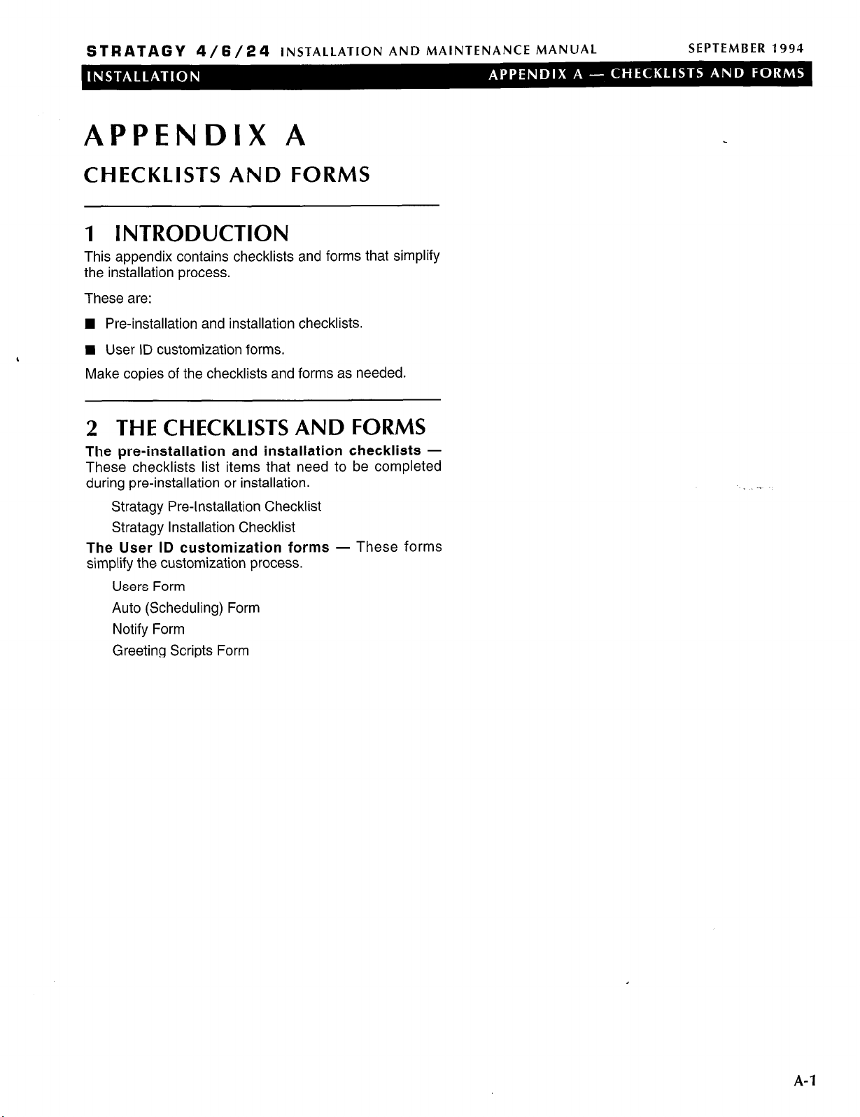
STRATAGY 4/6/24
INSTALLATION AND MAINTENANCE MANUAL
APPENDIX A
CHECKLISTS AND FORMS
1 INTRODUCTION
This appendix contains checklists and forms that simplify
the installation process.
These are:
n Pre-installation and installation checklists.
SEPTEMBER 1994
‘
n User ID customization forms.
Make copies of the checklists and forms as needed.
2 THE CHECKLISTS AND FORMS
The pre-installation and installation checklists -
These checklists list items that need to be completed
during pre-installation or installation.
Stratagy Pre-Installation Checklist
Stratagy Installation Checklist
The User ID customization forms
simplify the customization process.
Users Form
Auto (Scheduling) Form
Notify Form
Greeting Scripts Form
- These forms
-.
A-l

STRATAGY 4/6/24
INSTALLATION AND MAINTENANCE MANUAL
STRATAGY PRE-INSTALLATION CHECKLIST
SEPTEMBER 1994
DONE d ITEM
KNOW THE REFERENCE DOCUMENTATION
2
COMMENTS
(Installation section, Chapter 2, “Before You Install”)
Q - - - - - - - -
rJ - - - - - - - -
Q - - - - - - - r-J - - - - - - - -
-1. Know Stratagy’s
features.
-2. Know Stratagy operation, customization, and administration.
-3. Know Stratagy installation.
-4. Know how to configure the voice mail system settings for your
telephone system.
,
COMPLETED THE PRE-INSTALLATION SURVEY
0
(Installation section, Chapter
DETERMINED STRATAGY’S CONFIGURATION AND INTEGRATION
Ll
(Installation section, Chapter 2,
2,
“Before You Install”)
“Before You Install,” and Chapter 5,
“Configuring and Backing Up Stratagy”)
0 - - - - - - - Q - - - - - - - -
CUSTOMIZED USER ID MAILBOXES AND CALL PROCESSING
Ll
-1. Defined Stratagy system configuration options.
-2. Defined system integration options.
(completed the forms) (Programming section)
-.
Q - - - - - - - -
Q - - - - - - - rJ - - - - - - - Q - - - - - - - -
Q - - - - - - - -
SELECTED AND PREPARED THE HARDWARE SITES
cl
j-J - - - - - - - -
0 - - - - - - - -
-1. Determined the company greeting.
-2. Determined the caller instructions.
-3. Obtained the busy-hold music. (optional)
-4. Determined the employee directory instructions.
-5. Programmed the User IDS.
(installation section, Chapter 2, “Before You Install”)
-1. Stratagy system.
-2. Remote or local system (required for Stratagy 4 and 6).
CHECKLIST-1

STRATAGY
a/6/24 INSTALLATION AND MAINTENANCE MANUAL
STRATAGY INSTALLATION CHECKLIST
SEPTEMBER 1994
DONE d
INSTALLED THE HARDWARE
iI
(Installation section, Chapter 3, “Installing the Hardware”)
Q - - - - - - - 0 - - - - _ - - 0 - - - - - - - -
D - - - - - - - -
0 - - - - - - - -
0 - - - - - - - 0 - - - - - - - -
0 - - - - - - - -
1 CONFIGURED STRATAGY USING THE STRATAGY CONFIGURATION UTILITY
-1. Inspected and unpacked the system.
-2. Installed Stratagy Voice Boards (as appropriate).
-3. Set up the Stratagy system PC hardware.
-4. Configured your telephone system’s voice mail system settings
individually (as appropriate).
-5. Connected line cords from the voice boards to the telephone
system.
-6. Verified Stratagy’s basic functions.
-7. Prepared (hardware and software) the remote or local system to
access the Stratagy host system (required for Stratagy 4 and 6).
-8. Accessed Stratagy directly, remotely, or locally.
(Installation section, Chapter 5, “Configuring and Backing Up
Stratagy)
ITEM
COMMEN’
0 - - - - - - - I-J - - - - - - - -
rJ
- - - - - - - -
CUSTOMIZED USER ID MAILBOXES AND CALL PROCESSING
Ll
rJ
- - - - - - - Q - - - - - - - r-J - - - - - - - 0 - - _ - - - - rJ
- - - - - - - Q - - - - - - - -
-1. Defined Stratagy system configuration options.
-2. Defined Stratagy integration options.
n For a Toshiba telephone system, selected the appropriate
system.
n For a non-Toshiba telephone system, defined:
B - - - - - - D -------
_--me--
cl
-3. Backed up Stratagy using the Stratagy Backup Utility.
(entered the data from the forms completed during pre-installation)
(Programming section)
-1. Recorded the company greeting.
-2. Recorded the caller instructions.
-3. Recorded the busy-hold music. (optional)
-4. Recorded the employee directory instructions.
-5. Programmed the User IDS.
-6. Backed up Stratagy using the Stratagy Backup Utility
Telephone system dial codes.
Telephone system tone patterns.
System integration options.
,
CHECKLIST-2
 Loading...