

Page 1
TEC Electronic Computing Scale
SL-5300 SERIES
Owner's Manual
Page 2
This equipment has been tested and foun d to comply with the limits f or a Class A digital d evice,
pursuant to Part 15 of the FCC Rules. These limits are designed to provide reasonable
prot ection against harmful interference when the equipm ent is operated i n a commercial
environment. This equipment generates, uses, and can radiate radio frequency energy and, if
not installed and used in accordance wi th the instruction manual, may cause harmful inter ference
to ra dio communications. Operations of this equipment in a resi dential ar ea is likely t o caus e
harmful i nterference in which case the user will be required to correct the interference at his own
expense. (for USA only)
Changes or modifications not expressly approved by manufacturer for compliance could void the
user’s authority to operate the equipment.
“This Class A digital apparatus meets all requirements of the Canadian Interf erence-Causing
Equipment Regulations.” “Cet ap pareil numéique de la classe A respecte toutes les exigen ces
du Rèlement sur le materiel brouilleur du Canada.”
Some procedures described in this manual may be i llegal in various state jurisdic tions. When
there are optional setti ngs to enable various functions or to disable functions. Please ensure that
the optional settings for scale operation meet the local re quirements of weights and measures. If
you are uncertain of specific items, contact the state or county office of weights and measures for
clarification.
(for CANADA only)
Copyright © 2004
by TOSHIBA TEC CORPORATION
All Rights Reserved
570 Ohito, Ohito-cho, Tagata-gun, Shizuoka-ken, JAPAN
Page 3
Safety Summary
Safety Summary
Personal safety in handling or maintaining the equipment is extremely important. Warnings and Cautions
necessary for safe handling are included in this manual. All warnings and cautions contained in this manual
should be read and understood before handling or maintaining the equipment.
Do not attempt to effect repairs or modifications to this equipment. If a fault occurs that cannot be rectified
using the procedures described in this manual, turn off the power, unplug the machine, then contact your
authorized TOSHIBA TEC representative for assistance.
Meanings of Each Symbol
This symbol indicates warning items (including cautions).
Specific warning contents are drawn inside the symbol.
(The symbol on the left indicates a general caution.)
This symbol indicates prohibited actions (prohibited items).
Specific prohibited contents are drawn inside or near the symbol.
(The symbol on the left indicates “no disassembling”.)
This symbol indicates actions which must be performed.
Specific instructions are drawn inside or near the symbol.
(The symbol on the left indicates “disconnect the power cord plug from the outlet”.)
EO1-31009
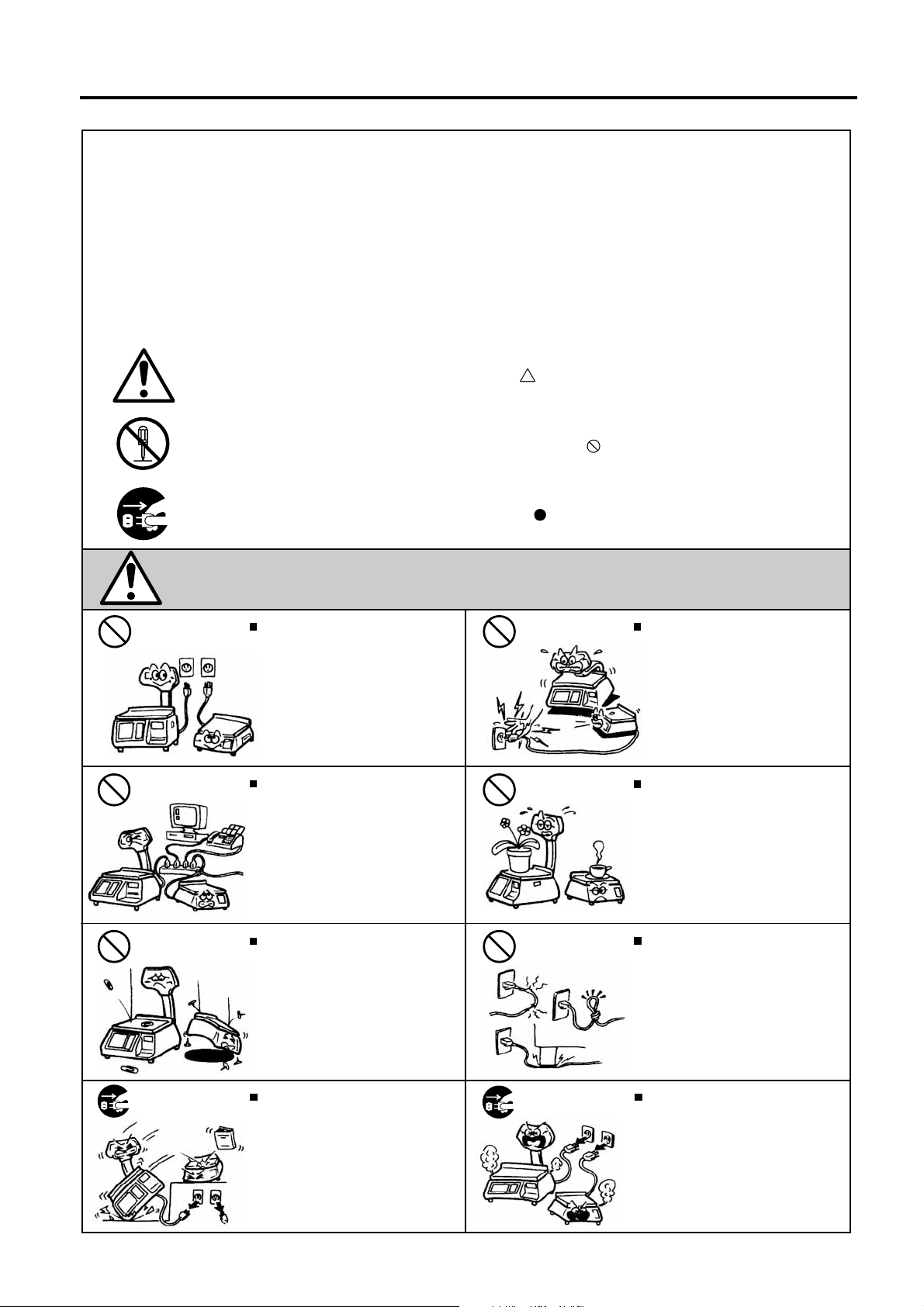
W ARNING
Any other than the
specified AC voltage is
prohibited.
Prohibited
Prohibited
Do not use voltages other than
the voltage (AC) specified on the
rating plate, as this may cause fire
or electric shock.
If the machines share the same
outlet with any other electrical
appliances which consume large
amounts of power, the voltage will
fluctuate widely each time these
appliances operate. Be sure to
provide an exclusive outlet for the
machine as this may cause fire or
electric shock.
Do not insert or drop metal,
flammable or other foreign objects
into the machines through the
ventilation slits, as this may cause
fire or electric shock.
This indicates that there is the risk of death or serious injury if the
machines are improperly handled contrary to this indication.
Prohibited
Prohibited
Prohibited
Do not plug in or unplug the power
cord plug with wet hands as this may
cause electric shock.
Do not place metal objects or
water-filled containers such as
flower vases, flower pots or mugs,
etc. on top of the machines. If metal
objects or spilled liquid enter the
machines, this may cause fire or
electric shock.
Do not scratch, damage or modify
the power cords. Also, do not place
heavy objects on, pull on, or
excessively bend the cords, as this
may cause fire or electrical shock.
Disconnect
the plug.
If the machines are dropped or their
cabinets damaged, first turn off the
power switches and disconnect the
power cord plugs from the outlet, and
then contact your authorized
TOSHIBA TEC representative for
assistance. Continued use of the
machine in that condition may cause
fire or electric shock.
Disconnect
the plug.
Continued use of the machines in an
abnormal condition such as when the
machines are producing smoke or
strange smells may cause fire or elec-
tric shock. In these cases, immediately turn off the power switches and
disconnect the power cord plugs from
the outlet. Then, contact your authorized TOSHIBA TEC representative for
assistance.
(i)
Page 4

Safety Summary
EO1-31009
Disconnect
the plug.
Connect a
grounding
wire.
If foreign objects (metal fragments,
water, liquids) enter the machines,
first turn off the power switches and
disconnect the power cord plugs from
the outlet, and then contact your
authorized TOSHIBA TEC representative for assistance. Continued
use of the machine in that condition
may cause fire or electric shock.
Ensure that the equipment is
properly grounded. Extension cables
should also be grounded. Fire or
electric shock could occur on
improperly grounded equipment.
Disconnect
the plug.
No disassembling.
When unplugging the power cords,
be sure to hold and pull on the plug
portion. Pulling on the cord portion
may cut or expose the internal wires
and cause fire or electric shock.
Do not remove covers, repair or
modify the machine by yourself. You
may be injured by high voltage, very
hot parts or sharp edges inside the
machine.
This indicates that there is the risk of personal Injury or damage to
CA UTION
objects if the machines are improperly handled contrary to this indication.
Precautions
The following precautions will help to ensure that this machine will continue to function correctly.
• Try to avoid locations that have the following adverse conditions:
* Temperatures out of the specification * Direct sunlight * High humidity
* Shared power source * Excessive vibration * Dust/Gas
• Do not subject the machine to sudden shocks.
• Do not press the keys too hard. Keys will operate correctly if they are touched lightly.
• Clean the cover and keyboard, etc. by wiping with a dry cloth or a cloth soaked with detergent and wrung out
thoroughly. Never use thinner or other volatile solvent for cleaning.
• To ensure that the scale is operating correctly, place a known weight on the platter and check it for correct
weight measurement. This should be done every morning before starting normal operations.
• When moving the machine, take hold of the case and lift the machine. Never hold the remote unit.
• Do not place the machines on unstable or slanted surfaces, as they may drop or fall and cause injury.
• USE ONLY TOSHIBA TEC SPECIFIED paper.
• DO NOT STORE the paper or ribbons where they might be exposed to direct sunlight, high temperatures,
high humidity, dust, or gas.
• Ensure the machine is operated on a level surface.
• Any data stored in the memory of the machine could be lost during a machine fault.
• Try to avoid using this equipment on the same power supply as high voltage equipment or equipment likely to
cause mains interference.
• Unplug the machine whenever you are working inside it or cleaning it.
• Keep your work environment static free.
• Do not place heavy objects on top of the machines, as these items may become unbalanced and fall causing
injury.
• Do not block the ventilation slits of the machines, as this will cause heat to build up inside the machines and
may cause fire.
• Do not lean against the machine. It may fall on you and could cause injury.
• Care must be taken not to injure yourself with the printer paper cutter.
• Unplug the machine when it is not used for a long period of time.
Request Regarding Maintenance
• Utilize our maintenance services.
After purchasing the machine, contact your authorized TOSHIBA TEC representative for assistance once a
year to have the inside of the machine cleaned. Otherwise, dust will build up inside the machines and may
cause a fire or a malfunction. Cleaning is particularly effective before humid rainy seasons.
• Our preventive maintenance service performs the periodic checks and other work required to maintain the
quality and performance of the machines, preventing accidents beforehand.
For details, please consult your authorized TOSHIBA TEC representative for assistance.
• Using insecticides and other chemicals
Do not expose the machines to insecticides or other volatile solvents. This will cause the cabinet or other
parts to deteriorate or cause the paint to peel.
(ii)
Page 5

EO1-31009
TABLE OF CONTENTS
Page
1. INTRODUCTION .................................................................................................................... 1-1
1.1 Applicable Model......................................................................................................... 1-2
1.2 Accessories................................................................................................................. 1-2
2. SPECIFICATIONS.................................................................................................................. 2-1
2.1 Scale........................................................................................................................... 2-1
2.2 Option.......................................................................................................................... 2-2
3. APPEARANCE....................................................................................................................... 3-1
3.1 Dimensions.................................................................................................................. 3-1
3.2 Scale........................................................................................................................... 3-1
3.3 Label Cassette.............................................................................................................3-1
3.4 Connector Panel.......................................................................................................... 3-2
4. PROCEDURE BEFORE DAILY OPERATION........................................................................ 4-1
4.1 Installation of the Scale................................................................................................ 4-1
4.2 Preparation.................................................................................................................. 4-1
5. INSERTING THE POWER CORD .......................................................................................... 5-1
6. LEVEL ADJUSTMENT........................................................................................................... 6-1
7. TURNING THE POWER ON/OFF........................................................................................... 7-1
7.1 Turning the Power ON................................................................................................. 7-1
7.2 Turning the Power OFF............................................................................................... 7-2
8. LOADING/REPLACING THE MEDIA..................................................................................... 8-1
9. OPERATION PANEL ............................................................................................................. 9-1
9.1 Operational Precautions.............................................................................................. 9-1
9.2 Tilt Angle Adjustment................................................................................................... 9-1
9.3 Layout of the Operation Panel..................................................................................... 9-2
10. CUSTOMER’S DISPLAY.......................................................................................................10-1
10.1 US Model....................................................................................................................10-1
10.2 CA Model....................................................................................................................10-2
10.3 Spanish Display Sticker..............................................................................................10-3
11. DAILY MAINTENANCE.........................................................................................................11-1
11.1 Cleaning.....................................................................................................................11-1
11.1.1 Print Head.......................................................................................................11-1
11.1.2 Platen and Media Roll Holder .........................................................................11-2
11.1.3 Covers and Platter..........................................................................................11-2
11.1.4 Operation Panel ..............................................................................................11-2
11.2 Removing the Jammed Media....................................................................................11-3
11.3 Media Guide Adjustment ............................................................................................11-4
12. PC CARD HANDLING...........................................................................................................12-1
12.1 Inserting the PC Card.................................................................................................12-1
12.2 Ejecting the PC Card..................................................................................................12-1
13. OUTLINE OF MAIN MENU....................................................................................................13-1
Page 6

EO1-31009
14. PROGRAMMING MODE.......................................................................................................14-1
14.1 Edit Screen................................................................................................................14- 2
14.2 PLU Data Setting.......................................................................................................14- 4
14.3 Department Setting...................................................................................................14-12
14.4 Ingredient Setting.....................................................................................................14-13
14.5 Nutrition Facts Setting ..............................................................................................14-14
14.5.1 Serving Size Setting......................................................................................14-18
14.5.2 Calories Setting ............................................................................................14-18
14.5.3 Nutrition Setting 1/2......................................................................................14-20
14.5.4 Nutrition Setting 2/2......................................................................................14-21
14.5.5 Additional Title Change 1/2...........................................................................14-23
14.5.6 Additional Title Change 2/2...........................................................................14-24
14.5.7 Footnote Setting ...........................................................................................14-25
14.6 Recipe Setting..........................................................................................................14-26
14.7 Grade Line Setting....................................................................................................14-28
14.8 Message/Information Setting....................................................................................14-29
14.9 Store Name/Address Setting....................................................................................14-30
14.10 Scrolling Message Setting........................................................................................14-31
14.11 Combination Report Setting......................................................................................14-33
14.12 Vendor Setting..........................................................................................................14-42
14.13 SFKC Setting............................................................................................................14-43
14.14 Idiom Setting............................................................................................................14-48
14.15 Combination Label Setting........................................................................................14-49
14.16 Promotion Setting.....................................................................................................14-51
14.17 Schedule Setting ......................................................................................................14-53
14.18 Inline (LAN Master/Satellite System) Setting............................................................14-55
14.19 DLL (LAN Master/Satellite System) Setting..............................................................14-56
14.20 Operator’s Hint Setting .............................................................................................14-58
14.21 Changing the Unit Price............................................................................................14-60
15. SETUP MODE.......................................................................................................................15-1
15.1 Date/Time Setting......................................................................................................15- 2
15.2 Label Format Setting.................................................................................................15- 3
15.2.1 Free Format Arrangement .............................................................................15- 6
15.2.2 Label Format List..........................................................................................15-10
15.2.3 Format Copy and New Format No. Addition..................................................15-10
15.2.4 Format Reset................................................................................................15-11
15.3 Bar Code Format Setting..........................................................................................15-30
15.4 Memory Card Operation...........................................................................................15-33
15.4.1 Save/Load Operation....................................................................................15-34
15.4.2 Memory Card Format....................................................................................15-37
15.4.3 Clear File in Scale Memory...........................................................................15-38
15.4.4 Memory Card Copy.......................................................................................15-39
15.5 PLU Data Maintenance.............................................................................................15-40
15.6 Password Assignment..............................................................................................15-47
15.7 Wireless LAN............................................................................................................15-48
15.7.1 Wireless LAN Setup......................................................................................15-49
15.7.2 Wireless LAN Status Check.......................................................................... 15-51
16. REGISTRATION MODE........................................................................................................16-1
16.1 Programming for the Registration Mode....................................................................16- 3
16.1.1 Print Item Selection........................................................................................16- 4
16.1.2 Label Format Selection..................................................................................16- 5
16.1.3 Mode Change................................................................................................16- 5
16.1.4 PLU Library....................................................................................................16- 6
16.1.5 Temporary Date Change ...............................................................................16- 8
Page 7

EO1-31009
e
16.1.6 Special Information Assignment.....................................................................16- 9
16.1.7 Logo Assignment..........................................................................................16-10
16.1.8 Grade Line Assignment................................................................................16-11
16.1.9 Scrolling Message Setting ............................................................................16-12
16.1.10 Store Name/Address Assignment...............................................................16-13
16.1.11 Operation Panel Brightness Adjustment......................................................16-14
16.2 Basic Operations......................................................................................................16-15
16.2.1 Zero Count Setting........................................................................................16-15
16.2.2 Calling a PLU................................................................................................16-16
16.2.3 Weighing Commodities and Issuing Labels...................................................16-18
16.2.4 Tare Subtraction/Cancellation/Save..............................................................16-19
16.2.5 Void..............................................................................................................16-24
16.2.6 Vendor Log-in...............................................................................................16-24
16.2.7 Unit Price Set and Change............................................................................16-26
16.2.8 Changing the Unit of Weight (CA model only)...............................................16-28
16.2.9 Label Issue Count Setting.............................................................................16-29
16.2.10 Test Print....................................................................................................16-30
16.2.11 Speed Key Screen Change.........................................................................16-30
16.3 By Count Operations ................................................................................................16-31
16.3.1 When Using the Quantity Preset to the PLU.................................................16-31
16.3.2 When Invalidating the Quantity and
Changing the Unit Price Preset to the PLU...................................................16-32
16.3.3 Batch Print Operation....................................................................................16-36
16.4 Fix Price Operation (US model only).........................................................................16-38
16.5 Issuing Net Weight Statement Label (US model only)...............................................16-39
16.6 Sales Promotion.......................................................................................................16-41
16.7 Average Portion Cost................................................................................................16-43
16.8 Operator’s Hint.........................................................................................................16-45
17. REGISTRATION MARK DOWN MODE ................................................................................17-1
18. REGISTRATION REWRAP MODE .......................................................................................18-1
19. REPORT/RESET MODE.......................................................................................................19-1
19.1 Label Mode Total Memory Report/Reset...................................................................19- 3
19.2 Programmed Data Report.........................................................................................19-13
19.3 Combination Report..................................................................................................19-19
19.4 Total Data Transmission...........................................................................................19-21
20. TRAINING MODE..................................................................................................................20-1
21. SLEEP MODE.......................................................................................................................21-1
22. SLIDE SHOW MODE ............................................................................................................22-1
23. TROUBLESHOOTING ..........................................................................................................23-1
24. ERROR MESSAGE TABLE..................................................................................................24-1
CAUTION!
1. This manual may not be copied in whole or in par t without prior written per mission of TOSHIBA TEC.
2. The contents of this manual may be changed without notification.
3. Please refer to your local Authorised Service representative with regard to any queries you may hav
in this manual.
Page 8

1. INTRODUCTION EO1-31009
1. INTRODUCTION
1. INTRODUCTION
Thank you for purchasing the TOSHIBA TEC SL-5300 Series Electr onic Com put ing Scale.
TEC SL-5300 series has many features and functions designed for user friendliness as well as
complete customer satisfaction. We believe t hat your needs will now be fully satisfied, and you will
have total reliability in price calculations.
Please read carefully and understand this manual to help gain maxim um performance of this product.
For most queries please refer to this m anual and keep it safe for future refer ence.
This scale has the following features:
[Operation Panel and Customer’s Display]
A 10.4-inch color TFT, a touch screen panel, and the tilt mechanism are adopted for the operat ion
panel, which provide wide viewing angle and much higher degree of operability.
The customer’s display is a built-in 2-row 5x7 dots by 20 columns vacuum fluorescent display (VFD). It
can be replaced with an optional display unit, such as a built-in 256x64-dot VFD and r em ote type
display.
[Printer]
Adoption of the front loading label cassette m akes t he m edia r eplacement easier and extra space for
the scale side unnecessary.
The printer can print up to 80-mm-wide labels with the maximum print speed of 4”/sec., allowing
production of a variety of print formats.
[Firmware]
The firmware of this machine enables the following functions.
1. Average unit price can be printed.
2. PLU library listed in alphabetic order
3. Sales promotion time schedule
4. “+Tax” can be printed on the label.
5. Some nutrition facts templat es ar e pr ovided.
6. Store coupon can be printed on the label.
7.Slide show is displayed on the operation panel.
8. Wireless LAN function is optionally available.
[Interface]
One RS-232C port and two slots of PCMCIA inter face are provided as standard. The PCMCIA
interface accommodates an Ethernet 10BASET ( LAN) and ATA card.
[Options]
The following options are available to this scale.
MEMO PC Board: PLU memory can be expanded up to 4MB.
Built-in 256x64-dot VFD: Replacing t he standard 5x7-dot VFD with the 256x64-dot VFD will m ake
the customers’ visibilities higher.
Remote Display: Two types of remote display: 5x7-dot VFD and 256x64- dot VFD ar e
available so that you can choose one according to your budget.
1- 1
Page 9

1. INTRODUCTION EO1-31009
SL-5300 SERIES
Owner's Manual
For end user's in the U.S.A.
SCALE/PRINTER
QUALITY CONTROL REPORT
1.1 Applicable Model
1.1 Applicable Model
• SL-5300-30M-US
• SL-5300-15M-CA
The description of the model number is as follows.
SL-5300-30M-US
Destination country/Region code
Ex) US, CA
Max. Capacity
30M: 30 lbs (decimal pound/multi-interval)
15M: 15 kg (multi-inter val)
1.2 Accessories
When unpacking, please check that the following accessories are supplied with the scale.
Owner’s Manual Print Head Cleaner TR-4x10 Screw N-8 Nut
(1 copy) (1 pcs.) (4 pcs.) (4 pcs.)
Sealing Lead Stranded Wire Sealing Cover Label
(2 pc.) (260 mm x 2 pcs.) (1 pc.)
Warranty Instruction Quality Control Report Spanish Display Sticker
(1 pc., US model only) (1 pc., US model only) (1 pc., CA model only)
Label (1 roll)
1- 2
Page 10

2. SPECIFICATION
EO1-31009
2.1 Scale
2. SPECIFICATION
2.1 Scale
Item 30 lb scale (US model) 15 kg scale (CA model)
Maximum capacity
Minimum Scale Division
Maximum Tare
Display Range
Unit Price Pre-settable
Minimum Price Display
Power Requirement
Power Consumption
Temperature Limits
Relative Humidity
Message Display
Unit Price
Total Price
Touch Panel
Capacity of PLU Memory
Print Head
Media Issue Method
Dot Density
Print Speed
Available Media width
Recommended Media
Thermal label
Variable length label
Thermal receipt
Interface
Dimensions (Approx.)
Weight
NOTE: The CA model is changeable between 30-lb scale and 15-kg scale as program option. For details,
please contact the nearest TOSHIBA TEC service representative.
30 lb
0.005 lb (0 to 15 lb)
0.01 lb (15 to 30 lb)
2 lb
0 to 30.05 lb
15 kg
0.002 kg (0 to 6 kg)
0.005 kg (6 to 15 kg)
1 kg
0 to 15.025 kg
$0.01 to $99.99
$0.01
AC 85V to 138V, 50/60 Hz±2%
90W/1.5A (when printing), 40W/0.6A (St and- by)
23°F to 95°F (-5°C to +35°C)
30% to 80% (No condensation)
Operator’s display: 10.4 inch color TFT display (640x480 dots)
Customer’s display: 5x7 dots 20 characters x 2 lines VFD (Standar d)
256x64 dots Full dot display (Opt ion)
4 digits
5 digits
Thin Film Resistor
2300 PLUs (standard), 17300 PLUs max. (Opt ion)
Thermal Print Head
Strip/Batch
203 dots/inch (8 dots/mm)
Supersensitive label: 4 inches/sec. (102 mm/sec.)
Normal sensitive label: 3 inches/sec. (76 mm/sec.)
1.89 to 3.15 inches (Variable length labels 1.89 or 2.24 inches)
48 mm to 80 mm (Variable length labels 48 mm or 57 mm)
VHTS, VHNS,GFTS,GFNS (OSP)/Outer diameter: ∅3.94 inches
(100mm) (Max.)
VHTS, VHNS,GFTS,GFNS (OSP)/Outer diameter: ∅3.94 inches
(100mm) (Max.)
PD-152R, PD-150R (OJI PAPER)/ Outer diameter: ∅3.15 inches
(80mm) (Max.)
PCMCIA interface 2 slots (LAN, ATA card, Wireless LAN)
RS-232C interface 1 channel
17.7 inches (W)x Max. 18.4 inches (D) x Min. 6. 1 inches ( H)
450 mm (W) x Max. 468 mm (D) x Min. 155 m m (H)
36.6 lb (16.6 kg)
2- 1
Page 11

2. SPECIFICATION
EO1-31009
2.2 Option
2.2 Option
Option Name Model No. Description
Built-in Customer’s
Display
Remote Customer’s
Display (Pole Type)
MEMO PC Board OP-5300-PIGGYBACK-1MB PLU Memory expansion PC board containing
Label Cassette KS-53 A spare label cassette
NOTE: To purchase these options, please contact the nearest TOSHIBA TEC service representative or
sales agent.
OP-5300-FBIU-US
(US model)
OP-5300-FBIU-CA
(CA model)
A 256x64-dot Vacuum Fluorescent Display
(VFD). Installing this display in place of the
standard 5x7-dot VFD enhances the customers’
visibility.
OP-5300-57PIU A 5x7-dot VFD (20 characters x 2 lines) remo t e
type customer’s display. When this option is
used, the standard customer’s display does not
work. Please take the height of the remote
display into consideration.
OP-5300-FPIU A 256x64-dot VFD remote type customer’s
display. When this option is used, the standard
customer’s display does not work. Please take
the height of the remote display into
consideration.
1M byte RAM as standard. The memory can be
expanded up to 4M bytes (Max. 17300 PLUs).
2- 2
Page 12
3. APPEARANCE EO1-31009
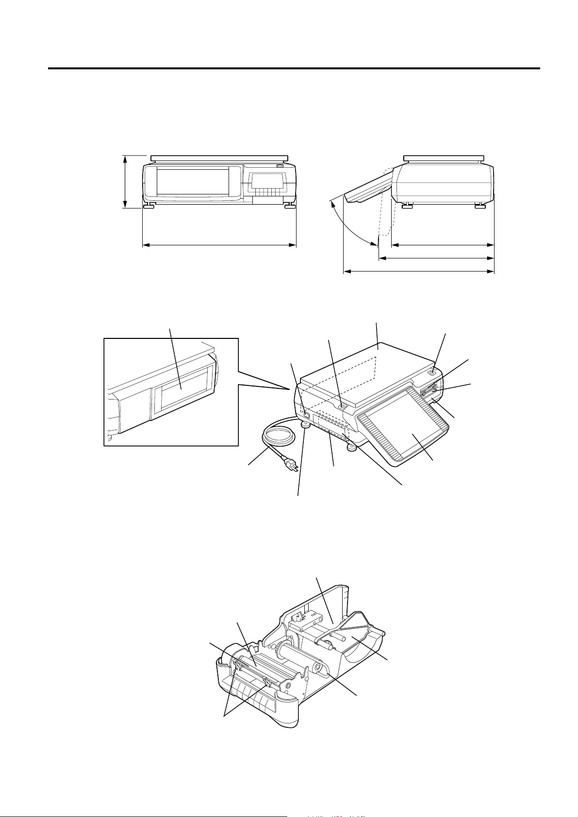
3.1 Dimensions
3. APPEARANCE
3.1 Dimensions
155 - 180
3.2 Scale
Customer’s Display
450
Power Cord
Level Gauge
Power Switch
Interface Cover
Adjustable Leg
25° - 85°
Platter
Connector Panel
310
410
464
Feed Button
Operation Panel
Cutter
Media Outlet
Label Cassette
3.3 Label Cassette
Strip Plate
Media Guide
Media Roll Holder
Platen
Media Roll Stopper
Backing Paper Stopper
3- 1
Page 13
3. APPEARANCE EO1-31009
(
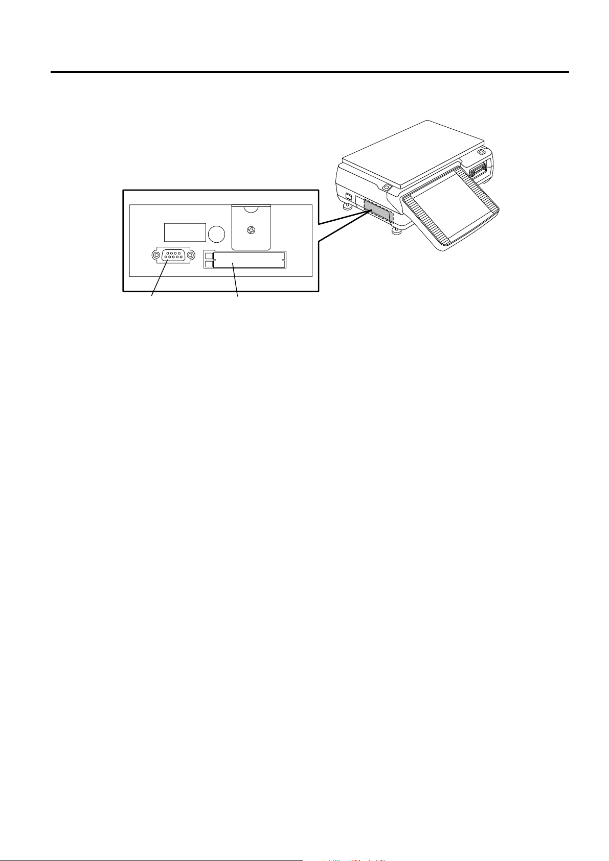
3.4 Connector Panel
3.4 Connector Panel
Serial Port
COM1)
PC Card Slot
3- 2
Page 14
4. PROCEDURE BEFORE DAILY OPERATION EO1-31009
e
4.1 Installation of the Scale
4. PROCEDURE BEFORE DAILY OPERATION
4.1 Installation of the Scale
When installing the scale, avoid locations that have the following adver se conditions. Failure to do this
may cause a fire, electric shock, or injury.
Direct sunlight, high temperature, high humidity, rapid temperatur e change, vibrations, dust, near a
device generating magnetism or electromagnet ic wave, near fire or moisture, unst able t able.
WARNING!
CAUTION!
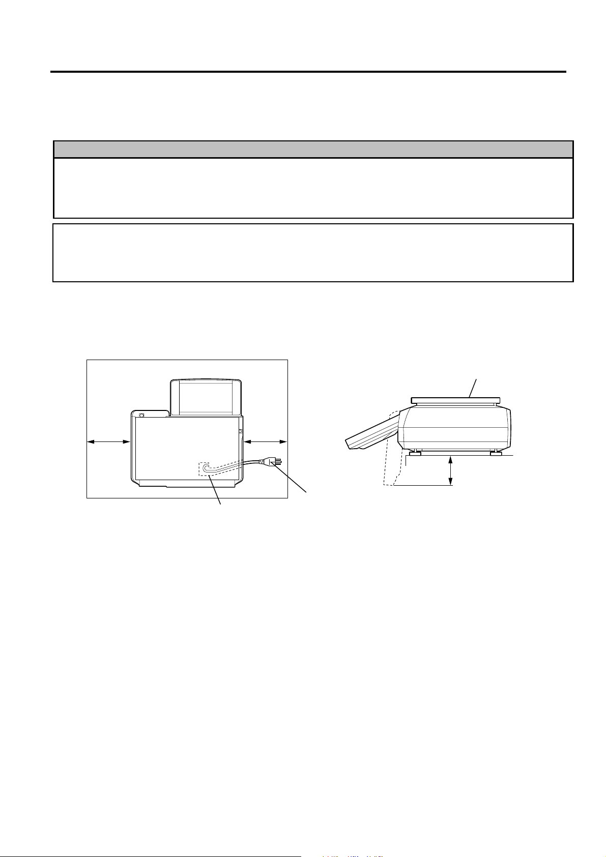
Basically, the power cord should come out from the left side of the scale being fitted into the ditch of th
scale bottom. If it cannot, car e m ust be taken when adjusting the adjustable legs so as not to squash
the power cord.
Install the scale on the well-ventilated, plane and level sur f ace. Be sure to provide enough space
around the scale as follows for easy operation.
As viewed from the top As viewed from the right side
Platter
50 mm 50 mm
NOTES:
1. Remove anything that touches or may touch the platter around the scale. Failure to do this may cause
incorrect weighing operation.
2. Avoid the location where the scale is subject to the direct wind from the air conditioner. Failure to do this
may cause incorrect weighing operation.
3. TOSHIBA TEC will not guarantee any problems with t he scale and t he per ipher al devices caused by
installation or removal of the peripherals by yourself.
Ditch
Power Cord
150 mm
4.2 Preparation
Before starting the business hours, perf or m the following preparatory operations.
1. Plug in the scale. (Refer t o Sect ion 5.)
2. Adjust the level of the scale. ( Ref er t o Section 6.)
3. Turn ON the power switch. ( Ref er to Section 7.)
4. Adjust the angle of the operation panel. (Refer to Section 9.)
5. Load the media. (Refer t o Section 8.)
After the business hour is over, clean the scale.
1. Turn OFF the power switch. (Refer to Section 7.)
2. Clean the scale. (Refer t o Sect ion 11.)
4- 1
Page 15
5. INSERTING THE POWER CORD EO1-31009
5. INSERTING THE PO WER CORD
5. INSERTING THE POWER CORD
1. Be sure to insert t he power plug into the rated outlet. Failure to do this may cause fire or electric
shock.
2. Do not share the same out let with any other electrical appliances or do not use an extension cor d.
Over capacity may cause fire or electric shock.
3. Do not excessively bend, pull on, damage, place a heavy object on, or heat the power cord.
Damaged power cord may cause fire or electric shock.
4. Do not plug in or unplug the power cor d wit h wet hands, as this may cause an electric shock.
5. Be sure to fully insert the power plug into the AC outlet. Failure to do t his may cause fire or electric
shock.
6. Be sure to hold and pull on the plug when disconnecting t he power cor d. Pulling on the cord instead
of the plug may break the internal wires, which may cause fire or electric shock.
7. Clean the plug for a few t im es a year . The power plug may collect dirt and this may cause fire.
WARNING!
CAUTION!
1. Do not share the AC outlet with any other electrical appliances that consume a large am ount of
power. Doing so may affect the operat ion of t his machine as the voltage will fluctuate widely each
time these appliances operate.
2. Be sure to turn O FF the power before plug in the power cord. Failure t o do t his m ay cause a shortcircuit resulting in a machine failure.
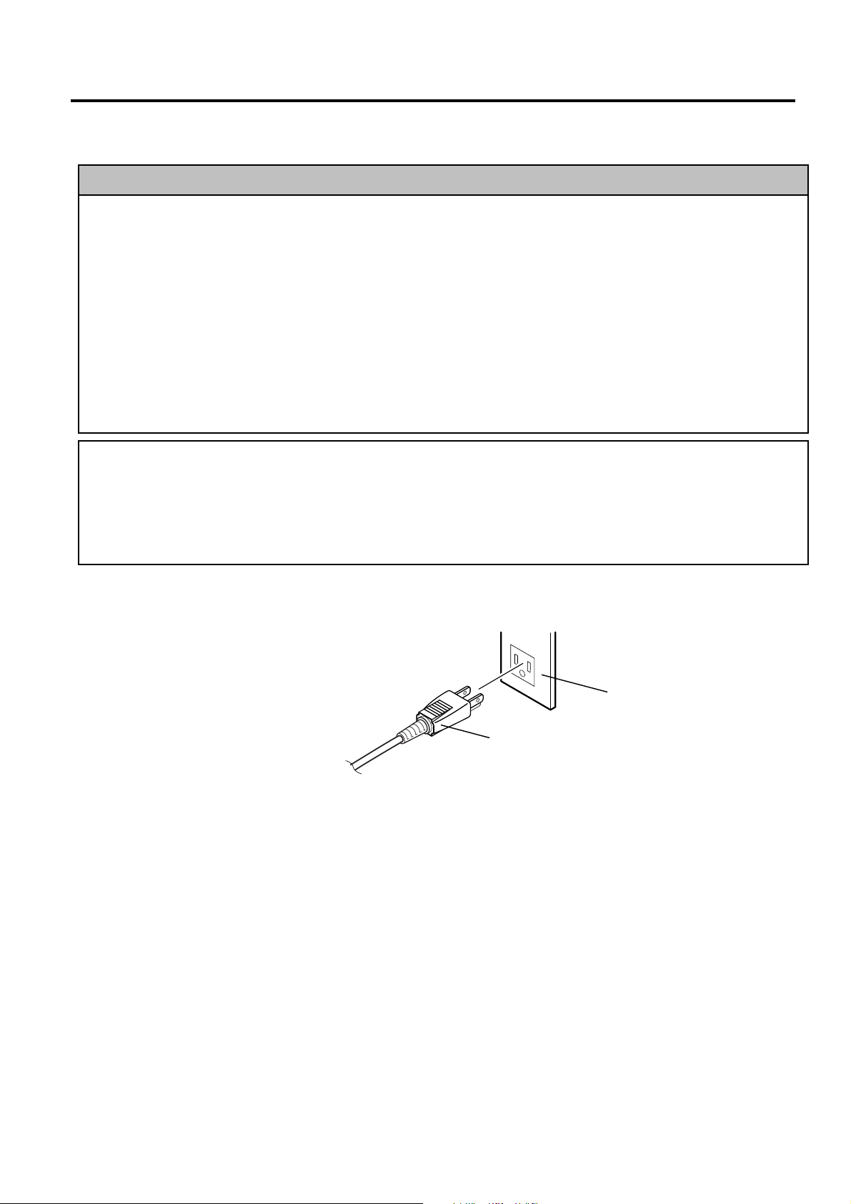
1. Make sure that the power swit ch is in the OFF position.
2. Insert the power plug into t he AC outlet completely.
AC Outlet
Power Plug
5- 1
Page 16
6. LEVEL ADJUSTMENT EO1-31009
6. LEVEL ADJUSTMENT
6. LEVEL ADJUSTMENT
Care must be taken not to squash the power cord by the scale when adjusting the level, as this may
cause electric shock or fire.
WARNING!
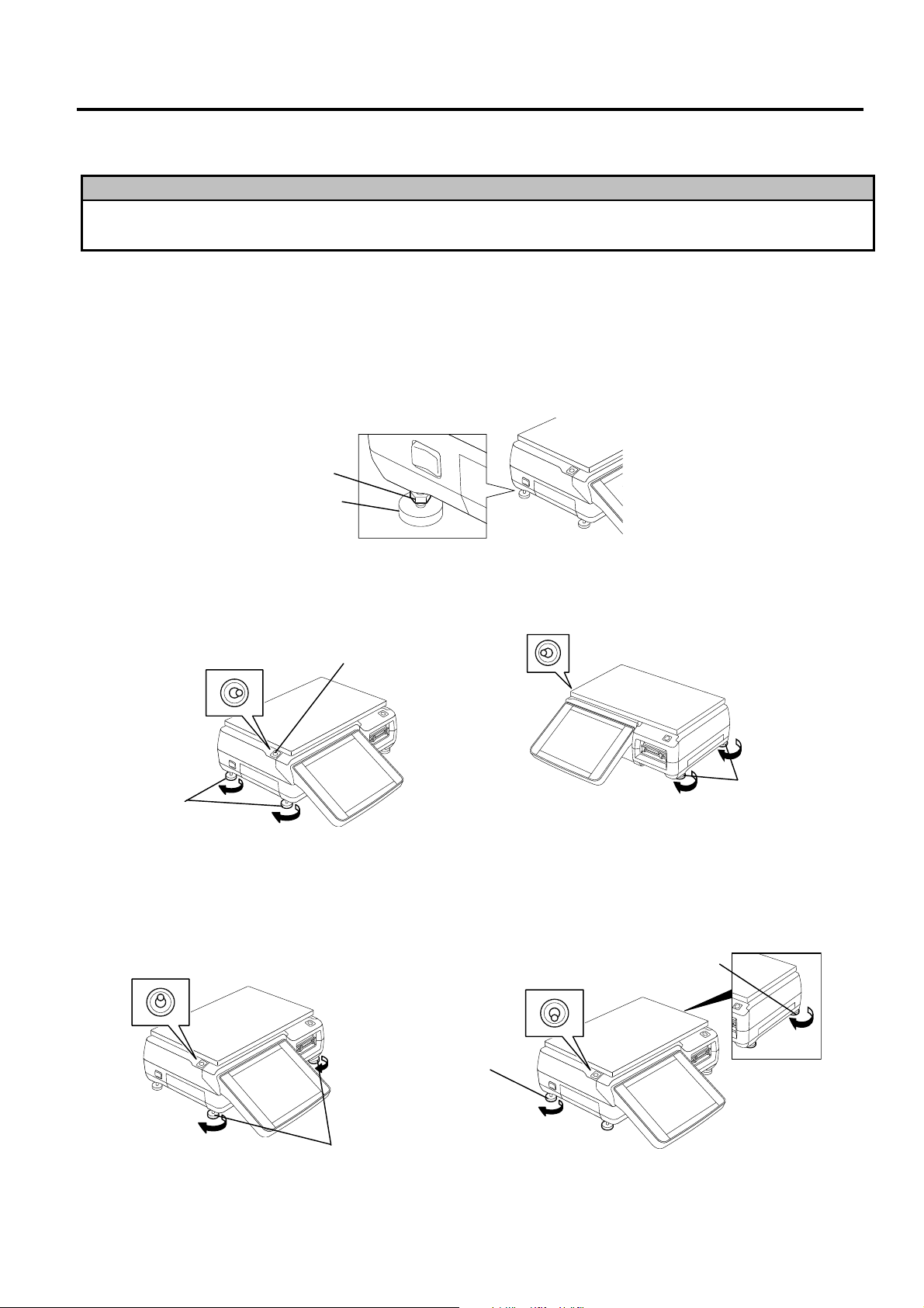
For correct weighing operations, be sure to level t he scale. Turn the four adjustable legs so that the
bubble in the level gauge is positioned at the center.
NOTES:
1. Make sure that the scale is leveled before the business hour starts.
2. To prevent the level adjustment from being changed unconsciously and the power cord from being
squashed, fixing the adjustable legs with the enclosed nuts is recommended.
Adjustable Leg
Nut
• When the bubble is positioned rightward.
Tur n the left adjustable legs clockwise, or
turn the right adjustable legs
• When the bubble is positioned leftward.
Tur n the right adjustable legs clockwise, or turn
the left adjustable legs counterclockwise.
counterclockwise.
Level Gauge
Left Adjustable
Legs
Right Adjustable Legs
• When the bubble is positioned backward.
Turn the front adjustable legs clockwise, or
turn the rear adjustable legs
counterclockwise.
•••• When the bubble is positioned frontward.
Tur n the rear adjustable legs clockwise, or turn
the front adjustable legs counterclockwise.
Rear Adjustable Leg
Rear Adjustable Leg
Front Adjustable Legs
6- 1
Page 17
7. TURNING THE POWER ON/OFF EO1-31009
7.1 Turning the Power ON
7. TURNING THE POWER ON/OFF
7.1 Turning the Power ON
1. Make sure that the power plug is f ully inser ted into the AC outlet.
2. Make sure that nothing is placed on the plat ter, and then turn ON the power swit ch.
NOTE: While the power switch is ON, the memory backup battery is charged. Therefore, data in t he
memory may be deleted if the battery voltage drops. Consult your TOSHIBA TEC service
representative in case the scale will not be used for a long period of time ( mor e t han 30 days) .
3. The last display before turning OFF t he switch follows about 10-second scanning display.
NOTE: If the power does not turn on or an error message appears, refer to Section 23,
TROUBLESHOOTING or Section 24, ERRO R MESSAGE TABLE.
Power Switch
7- 1
Page 18
7. TURNING THE POWER ON/OFF EO1-31009
7.2 Turning the Power OFF
7.2 Turning the Power OFF
CAUTION!
1. Do not turn off the power during printing. Doing so may cause a paper jam or machine failure.
2. Do not turn off the power in the middle of operation. Doing so may cause a malfunction.
3. Do not turn off the power while the PC card is being accessed. Doing so may destroy t he
data in the PC card.
1. Make sure that the Registr ation Mode Initial screen or Main Menu is displayed.
2. Turn OFF the power switch.
Power Switch
7- 2
Page 19
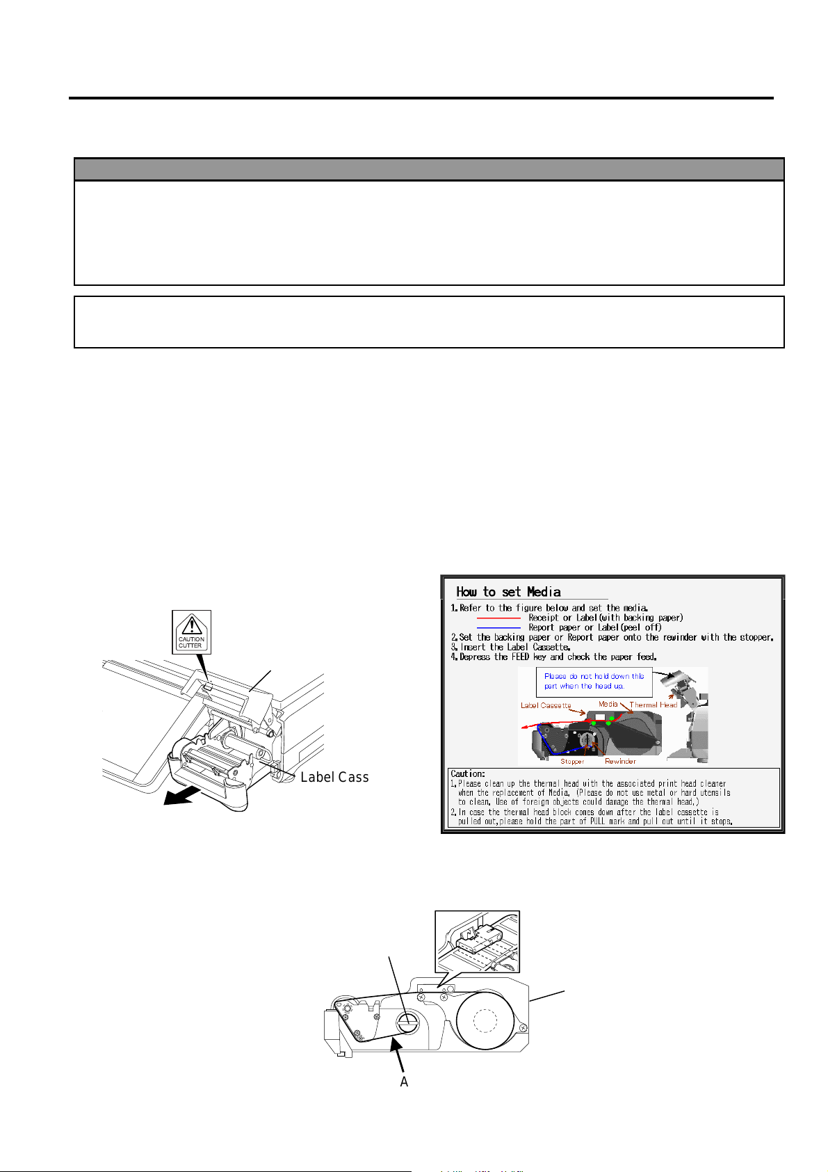
8. LOADING/REPLACING THE MEDIA EO1-31009
8. LOADING/REPLACING THE MEDIA
8. LOADING/REPLACING THE MEDIA
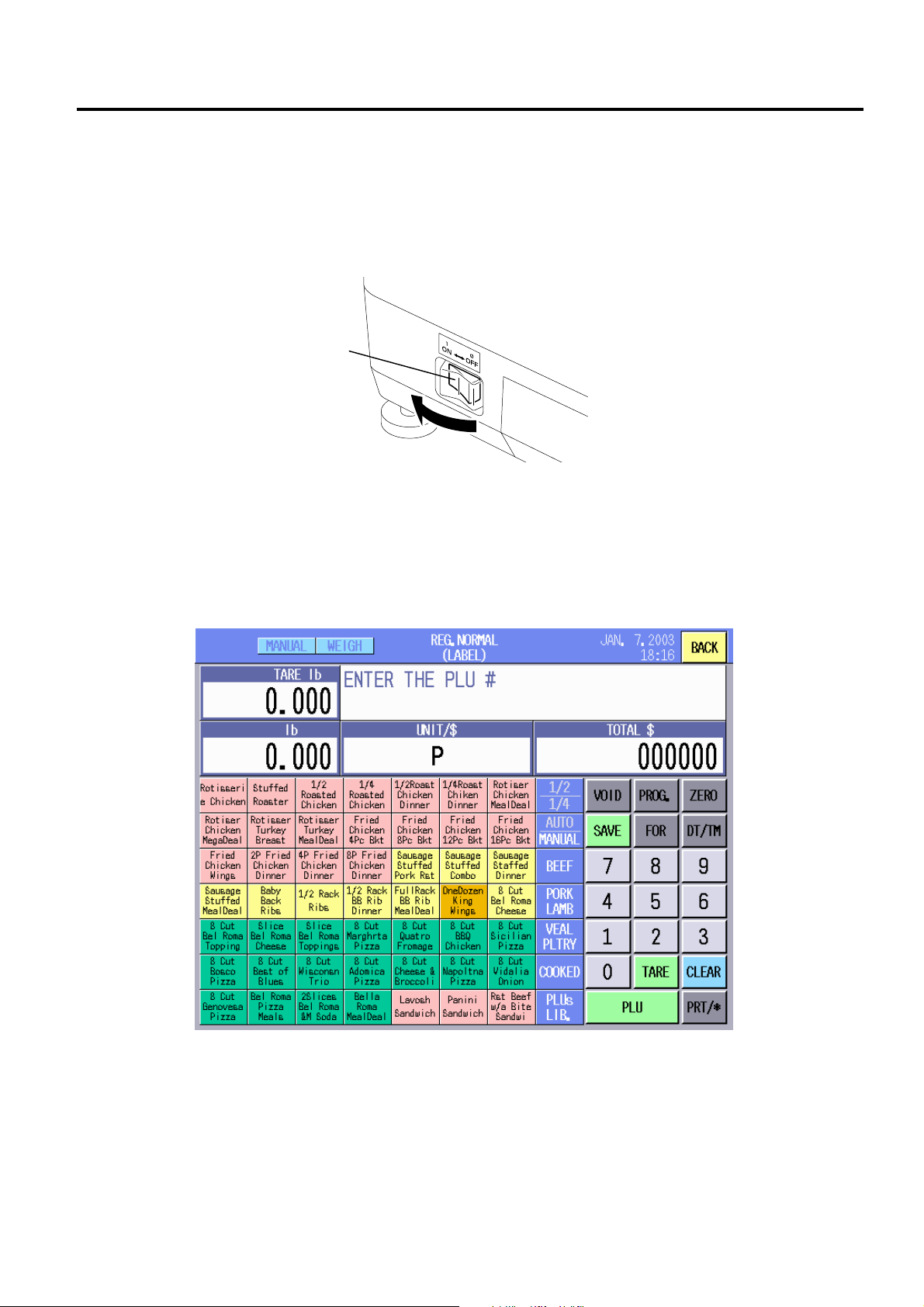
WARNING!
1. Do not touch the print head or around the print head, or you may get bur ned as t he pr int head
becomes very hot during printing.
2. Do not touch the cutter blade, as this may cause injury.
3. Firmly hold the bott om of the label cassette when pulling it out. Failure to do this m ay cause the
label cassette to drop, resulting in injur y .
CAUTION!
Do not push down or hit the print head, as this m ay cause a m achine f ailur e.
In this section how to load or replace the label is described. Please use TOSHIBA TEC-approved
labels only. For the label specification, refer to Section 2.1.
NOTES:
1. The label loading procedure differs according to the issue modes: Batch and Strip.
2. When purchasing the labels, contact the nearest TOSHIBA TEC service representative.
3. The loading procedure of receipt is same as that of the label. (Receipts are used in the Report and Reset
mode.)
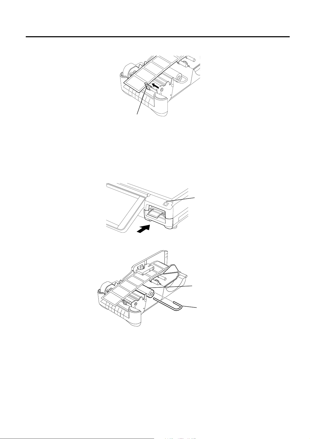
1. Pull out the label cassette. See the label loading procedur e displayed on t he oper ation panel just
for your reference.
Caution symbol for the cutter blade
(Please refer to WARNING!)
CAUTION
CUTTER
Print Head Block
Label Cassette
NOTE: When replacing the label, first cut the backing paper at the position of arrow A, remove the
backing paper stopper, move the media roll stopper to the right, and remove the label roll and
the backing paper roll from the label cassette.
Backing Paper Stopper
Label Cassette
A
8- 1
Page 20
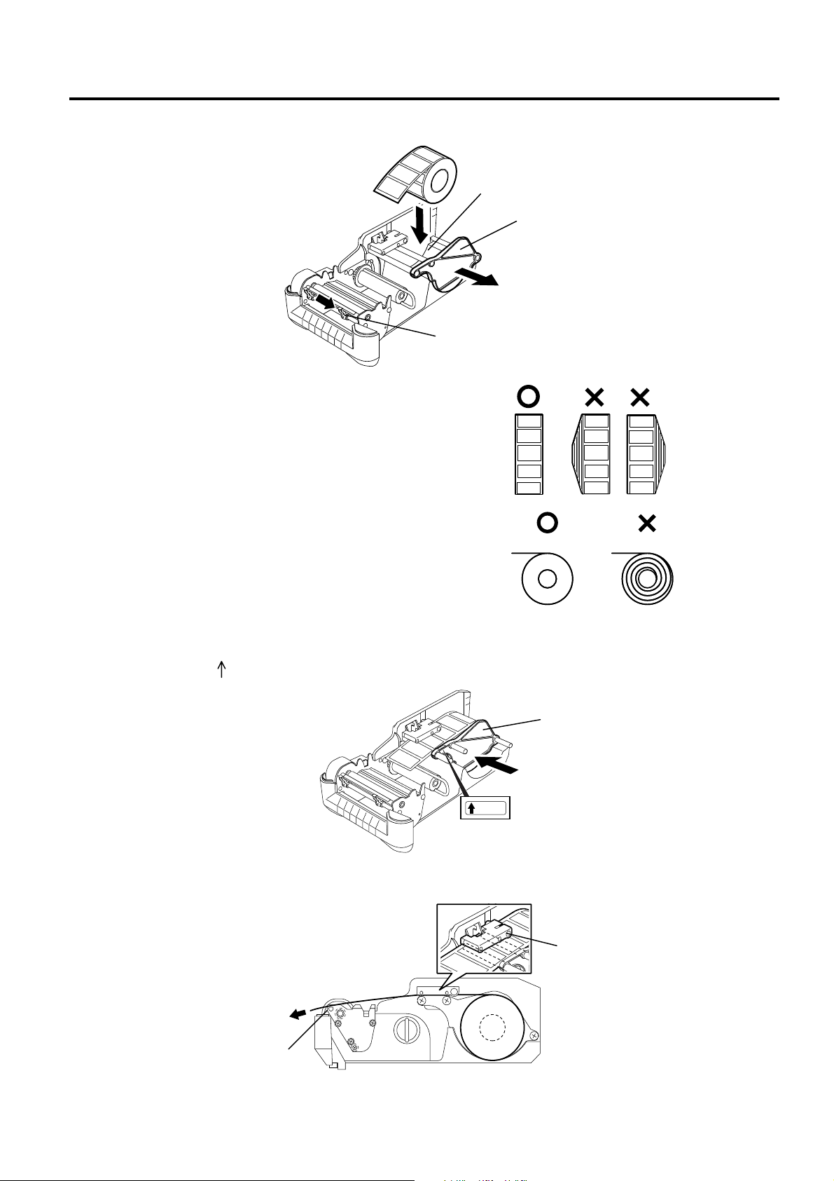
8. LOADING/REPLACING THE MEDIA EO1-31009
WIDTH
8. LOADING/REPLACING THE MEDIA
2. Move the media guide and the media roll stopper t o the right and place a label roll into the label
roll holder.
Label Roll Holder
Media Roll Stopper
NOTES: 1. When the inner part of the label roll is protruding,
flatten it on a level surface.
2. Do not use labels rolled loose, as this may
cause a paper jam. Re-roll the label tightly.
Media Guide
3. Move the media roll stopper t o t he label edge. Make sure that the label roll stopper’s f r ont part,
where the label “ WIDTH” is attached, is set along with the label edge.
4. Pull the top end of the label past the strip plate so that the labels pass under the pinch roller unit.
Strip Plate
Media Roll Stopper
Pinch Roller Unit
8- 2
Page 21
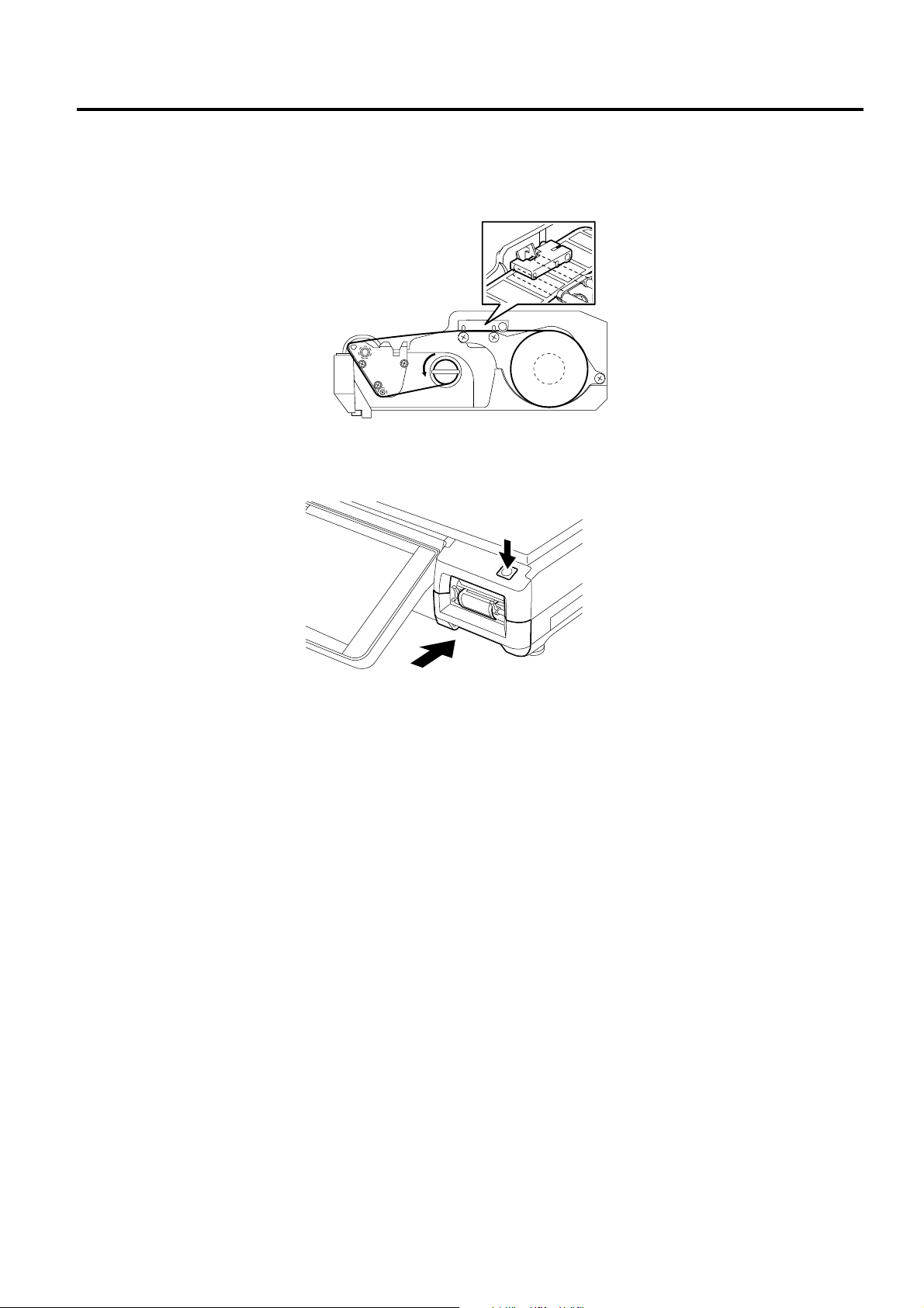
8. LOADING/REPLACING THE MEDIA EO1-31009
8. LOADING/REPLACING THE MEDIA
5. Move the media guide to the label edge.
Media Guide
NOTE: When the labels are issued in strip mode, provide about 1 mm gap between the backing paper
edge and the media guide.
6. To issue the label in the strip mode, skip t his st ep. To issue the label in the batch mode, push the
label cassette into the scale with the top edge of t he label pr otruding from the media outlet. Pr ess
the [FEED] button to check that the labels are fed properly. Now the label loading for t he bat ch
mode is completed.
FEED Button
7. When using the strip issue, remove the backing paper stopper from the take-up shaft.
Take-up Shaft
Backing Paper Stopper
8- 3
Page 22
8. LOADING/REPLACING THE MEDIA EO1-31009
8. LOADING/REPLACING THE MEDIA
8. Remove enough labels from the leading edge of t he label stock to leave 40 - 50 cm of backing
paper. Thread the backing paper through the print er as shown below, and fix the top edge of the
backing paper to the take-up shaft with t he backing paper st opper . Then turn the take-up shaft
counterclockwise for a few times.
9. Push back the label cassette into the scale, and press t he [FEED] button to check that t he labels
are fed properly.
8- 4
Page 23
9. OPERATION PANEL EO1-31009
9.1 Operational Precautions
9. OPERATION PANEL
9.1 Operational Precautions
The operation panel should be operated carefully. Follow the precautions provided below.
1. Though the operation panel is water - proof constructed, do not touch it with wet fingers or hands.
Doing so may cause electric shock or machine failure.
2. Should the liquid crystal leak out of the operation panel, do not touch it or you may have a r ash. If it
is attached to your skin or clothes, wash it away im m ediat ely with clean water.
CAUTION!
1. Operate the oper ation panel only with fingers. Do not use a sharp object like a pen, as t his m ay
cause a machine failure.
2. Just press the touch scr een panel lightly. Do not hit or give excessive pressure to the oper at ion
panel, as this may cause a machine failure.
3. Do not place anything on the operat ion panel. Doing so may cause a machine failure.
WARNING!
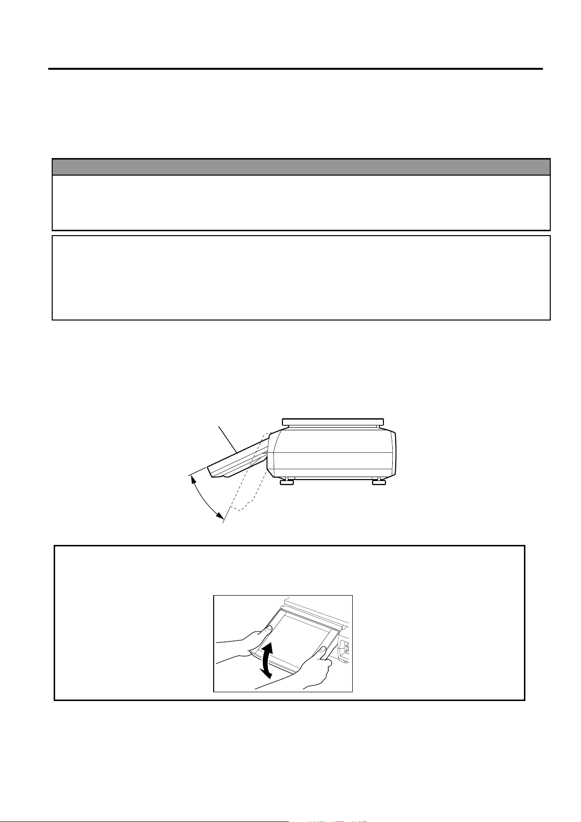
9.2 Ti lt Angle Adjustment
The tilt angle of the operation panel can be freely adjust ed in a r ange of 25° to 65°. Adjust the angle to
your best position so that the reflection of t he r oom light or outside light is minimized and you can
operate the operation panel at ease.
CAUTION!
Be sure to hold the frame of the operation panel when adjusting the tilt angle. Excessive
pressure to the display may cause a machine failure.
Operation Panel
25°
65°
9- 1
Page 24
9. OPERATION PANEL EO1-31009
(11)
(10)
(10)
(11)
(2)
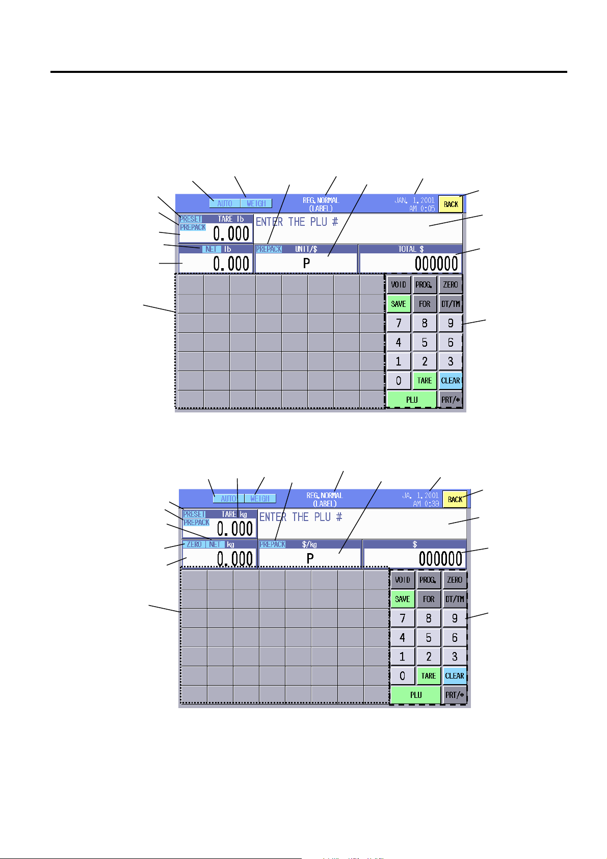
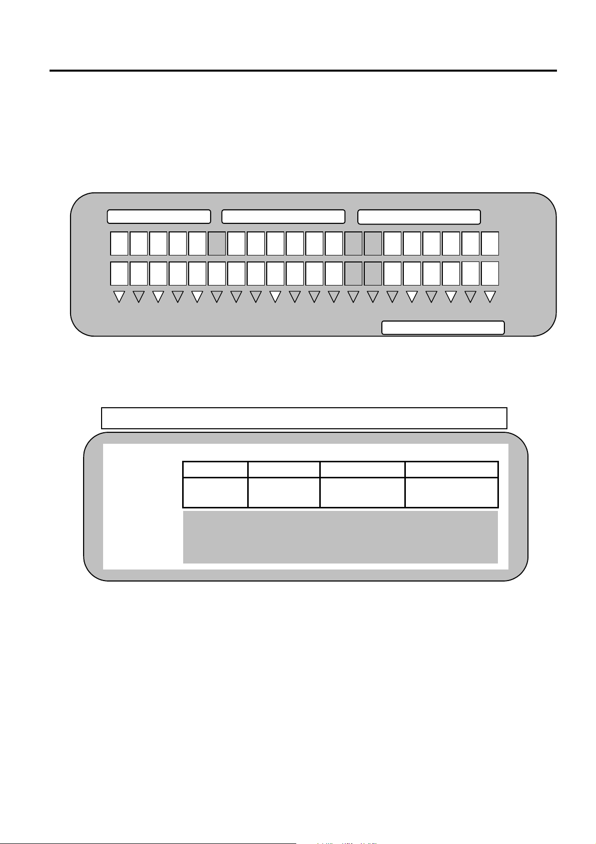
9.3 Layout of the Operation Panel
9.3 Layout of the Operation Panel
This section describes the layout of the screen displayed in the operation panel. The screen differs
according to the modes and menus. The examples shown below are those t hat appear in the
Registration mode.
1) US Model
(8)
2) CA Model
(8)
(1)
(14)
(2)
(15)
(3)
(14)
(15)
(17)
(3)
(1)
(13)
(13)
(16)
(16)
(6)
(6)
(12)
(4)
(5)
(7)
(9)
(12)
(4)
(5)
(7)
(9)
9- 2
Page 25

9. OPERATION PANEL EO1-31009
9.3 Layout of the Operation Panel
(1) Preset tare lamp: Lights when a tare preset to the PLU is called. (See NOTE.)
(2) Tare: Max. 4-digit tare is displayed.
(3) Weight: Max. 5-digit weight including “−“ mark is displayed.
(4) BACK key: Used to return to the previous screen.
(5) Commodity: A commodity name is displayed.
(6) Unit price: Max. 4-digit unit price is displayed.
(7) Total price: Max. 5-digit total price is displayed.
(8) Speed keys: You can freely program these keys by SFKC setting.
(9) Function keys: You can freely program these keys by SFKC setting.
(10) Scale mode: Current state of the scale is displayed (Weigh/By-count/Fix).
(11) Operating mode: Current operating mode is displayed (REG. NORMAL (Label)/REG. MARK
DOWN/REG. REWRAP).
(12) Date and Time
(13) AUTO/MANUAL lamp: The current label issue method is displayed.
(14) PREPACK (tare) lamp: Lights when the called PLU data or tare is retained.
(15) NET lamp: Lights when a tare is entered. In this case, a net weight will be displayed
on the Weight area.
(16) PREPACK (Unit Price) lamp: Lights when the called PLU data is retained.
(17) ZERO lamp: Lights when a tare is not set or nothing is placed on the platter (weight is
zero).
NOTE: With the initial settings, PLU preset tare function cannot be used. I f you desire t o use this function,
please contact the nearest TOSHIBA TEC service representative or sales agent.
9- 3
Page 26
10. CUSTOMER’S DISPLAY
10. CUSTOMER’S DISPLAY
10.1 US Model
• 5x7-dot Built-in Display (Standard)
• 5x7-dot Remote Display (OP-5300-57PIU)
EO1-31009
10.1 US Model
TARE lb PRICE/lb $ WEIGHT lb
CAPACITY 0-15 lb e= d=0.005 lb 15-30 lb e=d=0.01 lb
SCROLLING MESSAGE INDICATES SCALE AT ZERO.
0 . 0 0 0
0 . 0 0 0
P
E N T E R
P L U
#
0 0 0 0
0 0
%/T
PRESET-T
PREPACK
NET
REG. M/D R/W
TOTAL PRICE $
256x64-dot Built-in Display (OP-5300-FBIU-US)
•
256x64-dot Remote Display (OP-5300-FPIU)
•
<REG.>
MANU. WEIGH JN.01.02 17:45
TARE lb UNIT/$ lb TOTAL $
P-TARE
% TARE
PREPACK
ENTER THE PLU #
NOTE: Regarding the Remote Display, US, CA, and Spanish display stickers are enclosed in t he optional
kits so that you can choose the appropriate one from them. For the installation of t he opt ional kits,
please contact the nearest TOSHIBA TEC service representative or sales agent.
CAPACITY 0-15 lb e= d=0.005 lb 15-30 lb e=d=0.01 lb
SCROLLING MESSAGE INDICATES SCALE AT ZERO.
000000 P 0.000 0.000
10- 1
Page 27
10. CUSTOMER’S DISPLAY EO1-31009
10.2 CA Model
10.2 CA Model
• 5x7-dot Built-in Display (Standard)
• 5x7-dot Remote Display (OP-5300-57PIU)
TARE PRICE/PRIX $ WEIGHT/POIDS
CAPACITY 0-6 kg e=d=0.002 kg 6-15 lb e=d=0.005 kg
CAPACITÉ 0–15 lb e=d-0.005 lb 15-30 lb e=d=0.01 lb
0 . 0 0 0
0 . 0 0 0
P
E N T E R
P L U
#
0 0 0 0 0 0
PRESET T
PROG.-T
%T
PRÉ-EMBALLÉ
PREPACK
ZERO/
ZÉRO
NET kg
lb
100g
REG.
TOTAL $
M/D
R/W
• 256-64-dot Built-in Display (OP-5300-FBIU-CA)
• 256-64-dot Remote Display (OP-5300-FPIU)
<REG.> MANU. WEIGH JN.01.02 17:45
TARE kg $/ kg kg $
ZERO
P-TARE
% TARE
PREPACK
ENTER THE PLU #
NOTE: Regarding the Remote Displays, US, CA, and Spanish display stickers are enclosed in optional
kits so that you can choose the appropriate one from them. For the inst allat ion of t he opt ional kit s ,
please contact the nearest TOSHIBA TEC service representative or sales agent.
CAPACITY 0-6 kg e=d=0.002 kg 6-15 lb e=d=0.005 kg
CAPACITÉ 0–15 lb e=d-0.005 lb 15-30 lb e=d=0.01 lb
000000 P 0.000 0.000
10- 2
Page 28
10. CUSTOMER’S DISPLAY EO1-31009
10.3 Spanish Display Sticker
10.3 Spanish Display Sticker
• 5x7-dot Built-in Display (Standard)
• 5x7-dot Remote Display (OP-5300-57PIU)
TARA kg
0 . 0 0 0
PESO kg
E N T E R
TARE
PREDEFINIDA
%/T
FIJO
CERO 100g
• 256x64-dot Built-in Display (OP-5300-FBIU-CA)
• 256x64-dot Remote Display (OP-5300- FPI U)
NOTES:
1. Regarding the Built-in Displays, the Spanish display sticker is enclosed in the CA model machine.
Please contact the nearest TOSHIBA TEC service representative or sales agent when you desire to
use the Spanish display sticker.
2. Regarding the Remote Displays, US, CA, and Spanish display stickers are enclosed in the optional kits
so that you can choose the appropriate one from them. For the installat ion of the optional kits, please
contact the nearest TOSHIBA TEC service representative or sales agent.
CAPACIDAO 0-6 kg e=d=0.002 kg 6-15 kg e=d=0.005 kg TARA T= -1 kg Min. 0.04 kg
<REG.> MANU. WEIGH 01.06.02 17:45
TARE kg $/ kg kg $
ZERO
P-TARE
% TARE
PREPACK
ENTER THE PLU #
CAPACIDAO 0-6 kg e=d=0.002 kg 6-15 kg e=d=0.005 kg TARA T= -1 kg
PRECIO UNITARIO $/kg
0 . 0 0 0
P L U
#
0 0 0 0 0 0
REG. M/D R/W
PRECIO TOTAL $
P
Max 15 kg
Max 15 kg
Min. 0.04 kg
000000 P 0.000 0.000
10- 3
Page 29

11. DAILY MAINTENANCE
EO1-31009
11.1. Cleaning
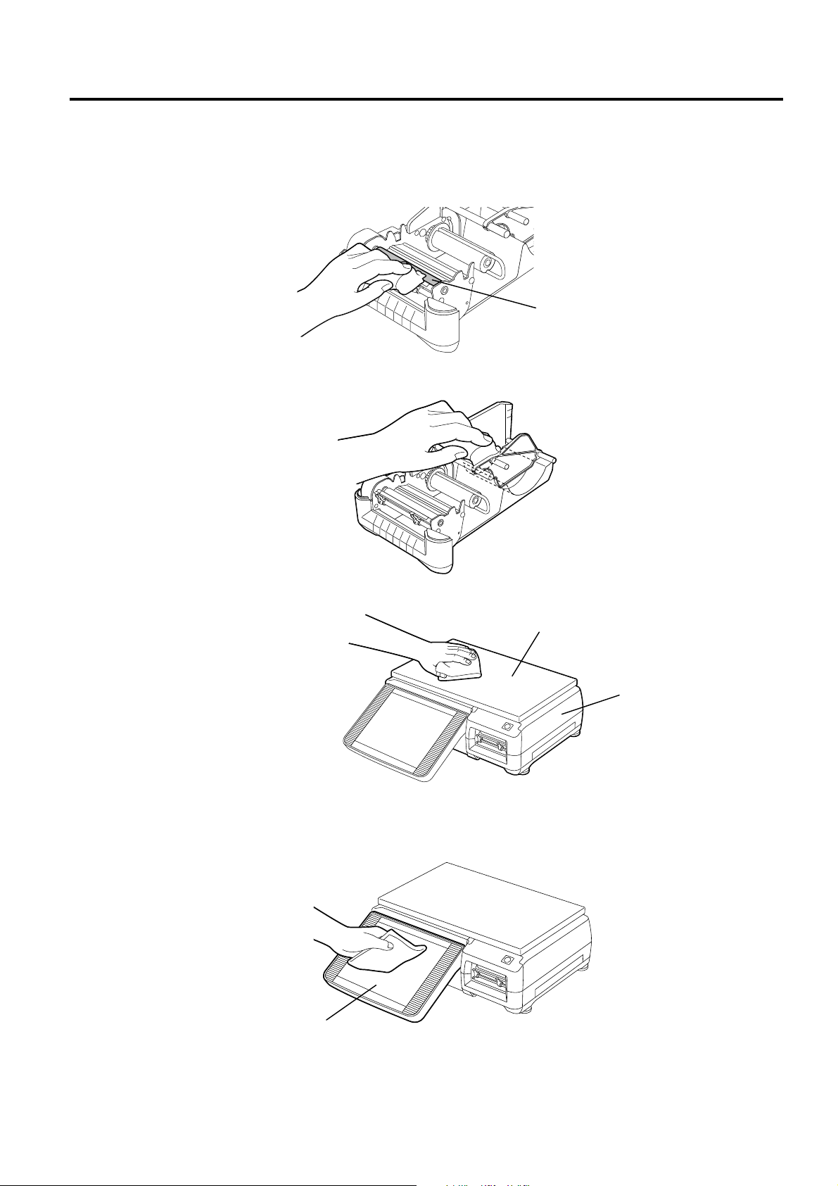
11. DAILY MAINTENANCE
Please clean the machine every day after the business hour finished so t hat you can always obtain
satisfactory performance of t he machine. Since the print head and the platen easily get dirt y, cleaning
is recommended whenever the media is replaced.
1. Do not pour water over t he scale or wipe it with soaked cloth. If water enters into the machine
inside, a fire or electric shock may occur.
2. Be sure to turn of f the power before cleaning. Failure to do this m ay cause a f ir e or electric shock.
3. Do not use thinner or benzine f or cleaning, as this may cause a fire.
4. Do not touch the print head or around it just after printing. You m ay get bur ned as the print head
becomes very hot during printing.
CAUTION!
1. Do not use a sharp object for cleaning the print head or platen. Doing so may damage them ,
causing a print failure or machine failur e.
2. Do not use thinner or benzine f or cleaning. Doing so may cause a print failure, machine failur e, or
discoloration.
3. Do not touch the print head element, as static electricity may dam age the print head.
4. Care must be taken not to give excessive pressure or shock to the platter and oper at ion panel.
Doing so may cause a machine failure.
5. Do not scratch or dam age t he operation panel with a sharp or hard object. Doing so may cause a
machine failure.
WARNING!
11.1 Cleaning
11.1.1 Print Head
1. Turn off the power switch.
2. Pull out the label cassette.
3. Clean the print head element (shaded par t in the figure below) with a print head cleaner enclosed
with the scale.
NOTE: Please purchase the print head cleaner (P/No. 24089500013) from your authorized TOSHIBA
TEC service representative.
Print Head Element
Print Head
Label cassette
Print Head Cleaner
11- 1
Page 30
11. DAILY MAINTENANCE
EO1-31009
11.1. Cleaning
11.1.2 Platen and Media Roll Holder
1. Turn off the power switch.
2. Pull out the label cassette and remove the media roll.
3. Wipe the platen with a soft cloth slightly moistened with alcohol.
4. Wipe out any dust or paper particles f r om t he media roll holder with a slightly moistened soft clot h.
Platen
11.1.3 Covers and Platter
1. Turn off the power switch.
2. Wipe the covers and platter with a dry soft cloth. For dirty parts, use a slightly moistened soft cloth.
11.1.4 Operation Panel
1. Turn off the power switch.
2. Wipe the surface of the operation panel wit h a dr y sof t cloth. For dirty parts, use a com m ercially
available OA cleaner.
Platter
Cover
Operation Panel
11- 2
Page 31

11. DAILY MAINTENANCE
11.2. Removing the Jammed M edi a
EO1-31009
11.2 Removing the Jammed Media
1. Turn off the power switch.
2. Pull out the label cassette.
CAUTION!
Do not push down or hit the print head block, as this m ay cause a m achine f ailur e.
3. Remove the jammed media.
4. Re-load the label roll correctly, and push the label casset t e into the scale with the top edge of the
label protruding from the media outlet . (Refer to Section 8. Loading/Replacing the M edia. )
Print Head Block
Label Cassette
Label Cassette
11- 3
Page 32

11. DAILY MAINTENANCE
11.3. Media Guide Adjustment
EO1-31009
11.3 Media Guide Adjustment
When the label skews in the strip mode, adjust the media guides so that a 1-mm clearance is given
between each guide and the backing paper edge.
1. Set the left side media guide at 2 mm from the left end. If t he media guide touches the backing
paper, move it left for about 1 mm.
2 mm
2. Set the right side media guide at about 1 mm f rom the right edge of the backing paper.
Right Side Media Guide
Left Side Media Guide
11- 4
Page 33

12. PC CARD HANDLING
12.1. Inserting the PC Card
EO1-31009
12. PC CARD HANDLING
This scale allows a use of commercially available PC cards (conforming to Types I to III). Regarding
the available PC card types, please refer to your TO SHI BA TEC service representative.
In this section, how to insert or eject a PC car d is descr ibed.
CAUTION!
1. Do not insert or eject a PC car d while the scale power is on. Doing so may destroy the data stor ed
in the PC card or PC card itself.
2. Do not eject a PC card or t ur n off the power while the PC card is being accessed. Doing so may
destroy the data stored in the PC card or PC card itself.
NOTES: 1. PC cards of Type I to Type III conforming to PCMCIA2.1JEIDA4.2 are available. However,
two Type III PC cards cannot be used at the same time.
2. For details of PC card handling, please refer to each PC card’s instruction.
12.1 Inserting the PC Card
1. Turn off the power switch, and open t he int er face cover by pushing the portion indicated by the
arrow.
2. Hold the PC card so that the front side f aces up and t he arrow mark points to the card slot, and
slowly insert it into the slot until it st ops.
PC Card Slot
3. Turn on the power switch.
Interface Cover
Arrow
Mark
PC Card
12.2 Ejecting the PC Card
1. First, make sure that t he PC car d is not being accessed, then, turn off the power swit ch.
2. Press the eject button and the PC card will pop out of t he card slot. Pull it out straight.
Eject Button
PC Card
12- 1
Page 34

13. OUTLINE OF MAIN MENU
13. OUTLINE OF MAIN MENU
EO1-31009
13. OUTLINE OF MAIN MENU
This section outlines the main menu of this scale.
1. After turning on the power switch, the operation panel will show the last screen of Regist r ation
Mode that was used just before the power off. It takes about 15 seconds.
2. Touching the [BACK] key causes the main menu to appear. Select t he desir ed m enu by touching
its key.
1
4
9
8
10
5
2
3
7
6
13- 1
Page 35

13. OUTLINE OF MAIN MENU
13. OUTLINE OF MAIN MENU
EO1-31009
The following table describes the contents of the m ain m enu and t heir functions.
Key Mode Function Refer to
1 REG.NORMAL
(LABEL)
In this mode, you can perform daily operat ions, such as,
weighing commodities, calling the registered PLUs, and
Section
16
issuing the desired number of labels. You can also change
the PLU data, select the print item s, and adjust the feed
amount, sensor sensitivity, and print tone.
2 SET UP In this mode, you can set the date/time, print items, label feed
amount, sensor sensitivity, print tone, label format, bar code
Section
15
types, print titles, password, et c. You can also read/write data
from/to the PC card.
3 PROGRAM In this mode, you can program the various settings required for
the daily operation, such as, unit price, ingredient, commodity
Section
14
name, message, store name and address, t are, SFKC, etc.
4 REPORT In this mode, you can check the total memory or issue the X
report of the totals registered in Registration Mode (NORMAL,
MARK DOWN, REWRAP). Also, it is possible t o send t he
registered data from the satellite scales to the master scale.
Section
19
5 RESET In this mode, you can r eset the total memory, issue the Z
report of the totals registered in Registration Mode (NORMAL,
MARK DOWN, REWRAP).
6 REG. MARK DOWN In this mode, the prices are reduced f r om the usual prices.
The transaction data in this mode will be stored separat ely
Section
17
from the Registration NORMAL (LABEL) Mode.
7 REG. REWRAP In this mode, rewrapped products are registered. The
transaction data in this mode will be stored separately from the
Section
18
Registration NORMAL (LABEL) Mode.
8 TRAINING (LABEL) This mode is a training mode intended for operators to lear n
how to operate this scale. Any operations performed in this
Section
20
mode will not change the data in the memor y.
9 SLEEP This is an energy saving mode that may be used when the
machine is not used for a long time.
10 SLIDE SHOW In this mode, programmed image data is displayed on the
operation panel.
Section
21
Section
22
The modes protected by the password are displayed with a key symbol. To enter these modes, first
input the password with the numeric keys, then touch the desired menu key.
NOTE: The Set Up mode has been protected by the initial settings. To enter the Set Up mode, t he mast er
password is required. For details, please contact the nearest TOSHIBA TEC service representat ive
or sales agent.
13- 2
Page 36

14. PROGRAMMING MODE EO1-31009
14. PROGRAMMING
MODE
14. PROGRAMMING MODE
In the Programming Mode, you can program various data required for the daily operation.
The following Programming Mode Main Menu screen will appear when the [PROGRAM] key of the
main menu is touched.
Programming Mode Main Menu screen
Numeric
Display area
The following keys will be used throughout the Programming Mode. As many other keys appear on the
screens hereinafter, refer to the following sections.
Key Functions
Key Function
BACK Used to return to the previous screen.
0 - 9 Used to input numeric data. The input number is displayed on the Numeric window on
the left side of the “1” key.
C Used to clear the input numeric data.
Used to scroll the screen.
Menu
PLU data
Department
Ingredient
Nutrition
Recipe
Grade line
............................
........................
...........................
.............................
...............................
..........................
Message/Information
Store name/address
Scrolling message
...........
..............
Combination report/reset
NOTE: The DLL (LAN) key is not displayed unless the scale is set t o be t he mast er. Ref er to the Inline
(LAN) mode for how to set the scale to the master.
Section 14.2 Vendor
Section 14.3 SFKC
Section 14.4 Idiom
Section 14.5 Confirmation Label
Section 14.6 Promotion
Section 14.7 Schedule............................. Section 14.17
.........
Section 14.8 Inline (LAN)
Section 14.9 DLL (LAN)
Section 14.10 Operator’s Hint
...
Section 14.11 Unit Price Change
................................
..................................
...................................
..............
............................
........................
..........................
....................
...............
Section 14.12
Section 14.13
Section 14.14
Section 14.15
Section 14.16
Section 14.18
Section 14.19
Section 14.20
Section 14.21
Back key
Scroll Bar
Clear key
Numeric keys
14- 1
Page 37

14. PROGRAMMING MODE EO1-31009
14.1 Edit Screen
14.1 Edit Screen
The Edit screen will appear when setting commodity names, department names, ingredient, nutrition
facts, recipe, grade lines, store messages, store name, address, vendors, etc. It can be used like a PC
keyboard.
Specified Code
Alphanumeric keys
Shift key
(Upper/Lower)
Bold/Normal key
Insert/Overwrite key
EURO Sign 1
EURO Sign 2
Space key
Key Functions
Key Function
Alphanumeric keys Used to input alphabets, numbers, and symbols.
Shift (upper/lower) Used to switch the case between the upper cases and the lower cases.
Bold/Normal Used to switch the font style between norm al and bold f ace.
Font style is not changed per character, but per line.
Insert/Overwrite Used to switch the typing mode between the insert and overwrite.
Space Used to insert a space.
Back space Used to delete the character in front of the cursor.
ENTER Used to add another line.
Used to move the cursor.
Del. Used to delete the selected character.
EURO Sign 1
EURO Sign 2
Used to show European characters or symbols.
Euro Sign 1 Euro Sign 2
Cursor
Del. key
Cancel key
Back Space key
Enter key
Cursor keys
Idiom key
Paste key
Copy key
Cancel Used to cancel the entry.
Copy Used to choose the character(s) to be copied. Touch this key when the cursor
is on the first and last characters of t he copy r ange.
Paste Used to paste the copied characters to the position of the cursor.
Idiom Used to call the idiom list (list of frequently used words)
14- 2
Page 38

14. PROGRAMMING MODE EO1-31009
14.1 Edit Screen
NOTES: 1. How to copy and paste
(1) Move t he cur s or t o the first character of the copy r ange, and then touch the [Copy]
key.
(2) Move t he cur s or t o the last character of the copy range, and t hen touch the [Copy]
key.
The copy range is shaded.
(3) Move t he cur s or t o the position where the selected copy range is pasted, and then
touch the [Paste] key.
(4) The selected copy r ange is copied.
2. How to apply boldface
Move the cursor to the line where bold is applied, and t he t ouch the [Bold] key. The
applied line is displayed in red.
3. Idiom
When the [Idiom] key is touched, the I diom list will appear. Select the desired idiom by
touching its area. Regarding the Idiom set t ing, r ef er to Section 14.14.
Idiom area
14- 3
Page 39

14. PROGRAMMING MODE
14.2 PLU Data Setting
EO1-31009
14.2 PLU Data Setting
A PLU (Price Look Up) includes not only a commodity name, but unit price, tare, shelf life, nutrition
facts, ingredient, etc. You can progr am or change the PLU data with this menu.
The following screen will appear when the [PLU data] key of the Programming Mode Main Menu is
touched. Since this menu consists of 3 screens, change the scr een wit h t he scroll key.
First screen
PLU No. and Dept. No. area
AUTO CODE area
MODE FLAG area
WEIGH
FIX
BY-COUNT
TARE LIMIT area
Key Functions
PLU# Used to call a registered PLU data.
Comm. Short Used to shorten the PLU’s commodity name. The shortened names are used as
PLUs Lib. Used to call the index of the commodity names.
ADD Used to add a new PLU.
NEXT PLU Used to call the PLU of next number.
LAST PLU Used to call the PLU of preceding number.
COPY Used to copy the PLU data to a new PLU.
DELETE Used t o delete the PLU data.
CHANGE PLU# Used to change the PLU No.
Commodity Name Area
Unit Price area
1ST. PRICE
2ND. PRICE
(Unused)
PIECES
Unit Price Flag area
per lb
per 1/2lb
per 1/4lb
per 1kg
per 100g
Tare area
PLU TARE
% TARE
COMPULSORY
YES or NO key
CHANGE PLU# key
DELETE key
COPY key
PLU# key
PLUs Lib. key
Comm. Short key
LAST PLU key
NEXT PLU key
ADD key
Key Function
the speed key names in SFKC setting.
14- 4
Page 40

14. PROGRAMMING MODE
Procedure
Item Procedure
Adding a new PLU 1. Input a new PLU No. (max. 6 digits)
2. Touch the [ADD] key.
NOTE: The top 2-digit number is the department No. There is no zero
suppression.
Calling a registered PLU 1. Input the PLU No. (max. 6 digits ) wit h the numeric keys.
2. Touch the [PLU#] key.
Commodity name 1. Touch the Commodity Name area.
2. The Edit screen will appear.
3. Edit a commodity name (max. 32 char act ers by 4 lines).
EO1-31009
14.2 PLU Data Setting
Making the commodity
name shorter
To shorten a single PLU’s name:
1. Call the PLU.
2. Touch the [Comm. Short] key.
3. The sub screen will appear.
4. Touch the [Single] key.
To shorten the all PLU names:
1. Touch the [Comm. Short] key.
2. The sub screen will appear.
3. Touch the [ALL] key.
NOTES:
1. A PLU name is shortened to 24 characters max.
2. The shortened commodity name is displayed in the Shortened commodity
name area. The commodity names can be also shortened by manual entry.
(Refer to the second screen on page 14-8.)
14- 5
Page 41

14. PROGRAMMING MODE
Item Procedure
14.2 PLU Data Setting
EO1-31009
Auto Code,
UPC
To set the auto code:
1. Touch the Auto code area.
2. The auto code setting screen will appear.
3. Input an Auto code (max. 6 digits).
4. Touch the [Decision] key.
To set the UPC:
1. Input a UPC (max. 6 digits).
2. Touch the UPC area.
Decision key
Asterisk key
NOTES:
1. Default: 000000
2. When the auto code has been entered, the UPC will become the same
number with the auto code.
3. When asterisks (*) are included in the auto code, the input code for UPC
can displace them, selected from the lowest digit. See t he examples below.
Example 1: Auto code = 123***, Input code for UPC = 6543
Example 2: Auto code = 98**54, Input code for UPC = 0211
Unit price 1. I nput a 4-digit number.
2. Touch the “1
st
Price” area.
nd
NOTE: The 2
Price cannot be used at present.
Unit price flag In case of the lb scale (US model):
Select “per 1lb”, ‘per 1/2 lb”, or “per 1/4lb”.
In case of the kg scale (CA model):
Select “per 1kg” or “per 100g”.
NOTE: Only “per 1kg” is selectable unless the initial settings are changed.
When “per 100g” is required, please contact the nearest TOSHIBA TEC
service representative or sales agent.
Mode flag Select “WEIGH”, “FIX”, or “BY-COUNT”.
NOTE: When “BY-COUNT” is selected, t he “ PI ECES” ar ea will need a
numeric data. Input the number for the “PIECES” area.
14- 6
Page 42

14. PROGRAMMING MODE
Item Procedure
14.2 PLU Data Setting
EO1-31009
Tare,
%Tare
Input a numeric data (max. 2lb for lb scale, 1kg for kg scale, or 99.9%
for %Tare).
NOTES:
1. With the initial settings, Preset tare and %Tare function is not available.
When these functions are required, contact the nearest TOSHIBA TEC
service representative or sales agent.
2. %Tare data exceeding the tare limit results in an error.
3. When the NET statement labels are to be issued, enter the net weight (0 –
480 oz) to the PLU tare area.
Tare Limit 1. Input a numeric data in the following range:
Lb scale: 0.000 – 2.000lb (Default: 2.000lb)
Kg scale: 0.000kg – 1.000kg (Default: 1.000kg)
2. Touch the Tare Limit area.
3. The confirmation screen will appear.
4. Touch the [Go] key to enter the data. To cancel, touch the [Cancel]
key.
NOTES:
1. With the initial settings, this funct ion is not available. When this function is
required, contact the nearest TOSHIBA TEC service representative or sales
agent.
2. If the actual tare exceeds the tare limit, an error occurs.
Compulsory tare
subtraction
Select YES or NO.
YES: Tare subtraction is compulsory.
NO: Tare subtraction is not compulsory.
NOTE: With the initial settings, YES cannot be selected. When this function
is required, contact the nearest TOSHIBA TEC service representative or
sales agent.
14- 7
Page 43

14. PROGRAMMING MODE
Second screen
SHELF LIFE area
PROMOTION area
LOGO area
LOGO1
LOGO2
LOGO3
Coupon LOGO
SAFE HANDLING area
OPERATOR’S HINT area
Procedure
Item Procedure
14.2 PLU Data Setting
Shortened Commodity Name area
EO1-31009
Relish area
FSP area
Discount $
Discount %
Bonus LOGO
FSP LOGO
GRADE LINE area
Shelf Life 1. Input a numeric data (max. 999 days).
2. Touch the “SHELF LIFE” area.
Relish 1. Input a numeric data (max. 999 days).
2. Touch the “RELISH” area.
Promotion 1. Input a sales promotion number. (1 – 99)*
2. Touch the PROMOTION area.
Or,
1. Touch the PROMOTION area.
2. The promotion list will appear.
3. Select the desired promotion number.
For details of the sales promotion, ref er to Section 14.16.
Grade Line 1. Input a grade line number (1 – 99)*.
2. Touch the GRADE LINE area.
Or,
1. Touch the GRADE LINE area.
2. The grade line list will appear.
3. Select the desired grade line from the list .
For details of the grade line, refer t o Section 14.7.
Operator’s Hint 1. Input an operator’s hint number ( 1 – 99) *.
2. Touch the OPERATOR’S HINT area.
Or,
1. Touch the OPERATOR’S HINT area.
2. The operator’s hint list will appear.
3. Select the desired operator’s hint fr om the list.
For details of the operator’s hint, r ef er to Section 14.20.
*: To clear the entered number, input “0”.
14- 8
Page 44

14. PROGRAMMING MODE
Item Procedure
FSP (Frequent Shoppers) To set the sale promotion schedule No.:
1. Input a schedule No. (1 – 99)*
2. Touch the FSP schedule area.
Or,
1. Touch the FSP schedule area.
2. The schedule list will appear.
3. Touch the desired schedule from the list.
For details of the schedule, refer to Sect ion 14.17.
To set the discount amount:
1. Input a numeric data (max. 999.99).
2. Touch the Discount area (left side).
To set the discount rate:
1. Input a numeric data (max. 99.9%).
2. Touch the Discount area (right side).
NOTES:
1. With the initial settings, the FSP function is not available. When this
function is required, contact the nearest TOSHIBA TEC service
representative or sales agent.
2. For the BONUS logo and FSP logo settings, refer to the NOTES for the
LOGO setting on the following page. However, the logo print area is limited
to the following size:
104 dots
118 dots
256 dots
3. The Bonus logo’s print area is shared by LOGO 3. Usually LOGO 3 takes
precedence over the Bonus logo except during the FSP schedule time
range.
4. The FSP logo’s print area is shared by Coupon logo. Usually Coupon
logo takes precedence over the FSP logo except during the FSP schedule
time range.
64 dots
EO1-31009
14.2 PLU Data Setting
Shortened Commodity
Name
1. Touch the Shortened commodity name area.
2. Input a short commodity name ( m ax. 24 characters) on the Edit
screen.
NOTE: When the commodity name is shortened by using t he [Comm.
Short] key, the first 24 characters of the commodity name are
automatically displayed in the Shortened commodity name area.
*: To clear the entered number, input “0”.
14- 9
Page 45

14. PROGRAMMING MODE EO1-31009
14.2 PLU Data Setting
Item Procedure
LOGO 1. Input a logo number (0000 – 9999)
2. Touch the LOGO area.
Or,
1. Touch the LOGO area.
2. The logo list will appear.
3. Select the desired logo number
from the list.
NOTES:
1. Max. 3 logos can be set to one PLU.
2. Logos can be called only from the flash memory card (ATA card).
3. File format, file name, and size of the logos should meet the f ollowing:
Format: Windows BMP, monochrome
File name: LOGOxxxx.BMP (xxxx is any 4-digit number and will be a code
number)
Size: Max. 600 dots (W) x 400 dots (H) (Both numbers must be multiple of
8.)
4. 1 pixel = 0.125 mm
For example, a 320-dots by 240-dot logo data will be printed as 40 mm by
30 mm.
5. Printable logo width differs depending on the label width.
Label width Printable logo width Print size
80 mm 600 dots 75 m m
57 mm 440 dots 55 m m
48 mm 380 dots 47.5 mm
Logos which are larger than the above size can be programmable,
however, the part outside the specified size will not be pr int ed.
Safe Handling Instructions 1. Input a safe handling instruction number (0 – 10).
2. Touch the SAFE HANDLING area.
NOTES:
1. Safe handling instructions can be called only from the flash memory card
(ATA card).
2.For the safe handling instruction’s format and size, refer to t he NOTES for
the LOGO setting. However, the file name should be set as follows:
File name: Shi00xx.bmp (xx is 2-digit number from 02 to 10)
3. Safe handling instruction No. 0 means that nothing is printed.
2. Safe handling instruction No. 1 means that the scale’s default dat a is
printed.
14- 10
Page 46

14. PROGRAMMING MODE
Third screen
NUTRITION area
+TAX PRINT area
ON OFF key
Procedure
Item Procedure
Ingredient 1. Input an ingredient number (1 – 3000)*.
2. Touch the INGREDIENT area.
Or
1. Touch the INGREDIENT area.
2. The ingredient list will appear.
3. Select the desired ingredient number fr om the list
For details of the ingredient message, ref er to Section 14.4.
Nutrition fact 1. Input a nutrition fact number (1 – 500)*.
2. Touch the NUTRITION area.
Or
1. Touch the NUTRITION area.
2. The nutrition fact list will appear.
3. Select the desired nutrition fact number f rom the list.
For details of the nutrition facts, r ef er to Section 14.5.
Recipe 1. Input a recipe number ( 1 – 1000)*.
2. Touch the RECIPE area.
Or,
1. Touch the RECIPE area.
2. The recipe list will appear.
3. Select the desired recipe number from t he list.
For details of the recipe, refer to Section 14.6.
Store name/address 1. Input a Store name/Address number ( 1 – 50) * .
2. Touch the Store name/Address area.
Or,
1. Touch the Store name/Address area.
2. The Store name/Address list will appear.
3. Select the desired Store name/Address f r om the list.
For details of the Store name/Address, refer to Section 14.9.
+TAX print Touch the [ON] or [OFF] key.
ON: “+TAX” is printed.
OFF: “+ TAX” is not printed.
“+TAX”
NOTE: “+TAX” means that the price
on the label is a before-tax price.
*: To clear the entered number, input “0”.
14- 11
EO1-31009
14.2 PLU Data Setting
INGREDIENT area
RECIPE area
Store name/
Address area
Page 47

14. PROGRAMMING MODE EO1-31009
14.3 Department Setting
14.3 Department Setting
You can set the department with this menu.
The following screen will appear when the [Department] key of the Programming Mode Main Menu is
touched.
Key Functions
SEARCH CODE Used to search the desir ed Dept . No. and display it on top of the list.
ADD
COPY Used to copy the data to other department.
DELETE Used to delete the desired department .
CHANGE CODE Used to change the Dept. No.
Procedure
Adding a new department 1. Input a 2-digit number . (00 – 99)
Selecting the Dept No. and
editing the Dept. name
Searching a Dept. No. 1. Input a Dept. No. you desire to search.
Copying Dept. name 1. Touch the Dept. No. ar ea of copy source.
Deleting the department 1. Touch the Dept. No. area to be deleted.
Changing the Dept. No. 1. Touch the Dept No. area you desire to change.
DEPT. NO. area
CHANGE CODE key
SEARCH CODE key
ADD key COPY key
DELETE key
Key Function
Used to add a new department. When the input number already exists, a
beep tone will sound.
Item Procedure
2. Touch the [ADD] key.
3. Touch the DEPT. NO. area.
4. Touch the data entry area.
5. Enter a Dept. name on the edit screen. (Max. 24 characters)
1. Touch the DEPT. No. area.
2. Touch the same DEPT. No. area again.
3. Edit the Dept. name on the edit scr een. ( M ax. 24 characters)
2. Touch the [SEARCH CODE] key.
2. Input the Dept. No. of copy dest inat ion.
3. Touch the [COPY] key.
2. Input the Dept. No.
3. Touch the [DELETE] key.
2. Input a new Dept. No. (2 digit s )
3. Touch the [CHANGE CODE] key.
14- 12
Page 48

14. PROGRAMMING MODE EO1-31009
14.4 Ingredient Setting
14.4 Ingredient Setting
You can set the ingredient data with this menu.
The following screen will appear when the [Ingredient] key of t he Programming Mode Main Menu is
touched.
SORT key
Key Function
Key Function
SORT Used to defr agm ent the data in the flash ROM.
Since this machine uses the flash ROM, repeated data input may disable the
data entry in spite of sufficient memory capacity. (“Memory not enough error” will
appear.)
When the [SORT] key is touched, the following confirmation screen will appear.
To execute, touch the [GO] key, or [CANCEL] key to cancel.
It takes a while to complete the data sort.
SEARCH CODE Used to search the desired Ingredient No. and display it on top of the list.
ADD Used to add a new ingredient. When the input number already exists, a beep
tone will sound.
COPY Used to copy the data to other ingredient.
DELETE Used to delete the desired ingredient.
CHANGE CODE Used to change the Ingredient. No.
ING. NO. area
SEARCH CODE key
ADD key
COPY key
DELETE key
CHANGE CODE key
14- 13
Page 49

14. PROGRAMMING MODE
Procedure
Item Procedure
Adding a new ingredient 1. Input a 4-digit ING. No. (0001 – 3000)
2. Touch the [ADD] key.
3. Touch the data entry area and enter the data.
Selecting an ING. No. and
editing the Ingredient
1. Touch the ING. No. area.
2. Touch the same ING. No. area again.
3. Edit the ingredient data on the edit screen. ( m ax. 54 characters x 38
lines)
Searching an ING. No. 1. Input the ING . No. you desire to search.
2. Touch the [SEARCH CODE] key.
Copying the Ingredient 1. Touch the ING. No. ar ea of copy source.
2. Input the ING. No. of copy destinat ion.
3. Touch the [COPY] key.
Deleting the Ingredient 1. Touch the ING . No. area to be deleted.
2. Input the ING. No.
3. Touch the [DELETE] key.
Changing the ING. No. 1. Touch the ING. No. area you desire to change.
2. Input a new ING. No.
3. Touch the [CHANGE CODE] key.
EO1-31009
14.5 Nutrition Facts Set ting
14.5 Nutrition Facts Setting
You can set the nutrition facts with this menu.
The following screen will appear when the [Nutrition] key of the Programming Mode Main Menu is
touched.
NUTRITION No. area
SORT key
SEARCH CODE key
ADD key
COPY key
CHANGE CODE key
DELETE key
14- 14
Page 50

14. PROGRAMMING MODE EO1-31009
14.5 Nutrition Facts Setting
Key Function
Key Function
SORT Used to defr agm ent the data in the flash ROM.
Since this machine uses the flash ROM, repeated data input may disable the
data entry in spite of sufficient memory capacity. (“Memory not enough error” will
appear.)
When the [SORT] key is touched, the confirmation screen will appear. To
execute, touch the [GO] key, or [CANCEL] key to cancel.
It takes a while to complete the data sort.
SEARCH CODE Used to search the desired Nutrition Fact s No. and display it on top of the list.
ADD Used to add a new Nutrition Facts No.
COPY Used to copy the data to other Nutrit ion Fact s No.
DELETE Used to delete the desired Nutrition Fact s No.
Procedure
Item Procedure
Adding a new Nutrition
Facts No.
1. Input a 3-digit Nutrit ion Fact s No. (001 - 500)
2. Touch the [ADD] key.
3. Touch the data entry area and enter t he dat a. (Refer to the Nutrition
Facts Programming screen on the following page.)
Selecting a Nutrition Facts
No. and editing the Nutrition
Facts
Searching a Nutrition Facts
No.
1. Touch the NUTRITION No. area.
2. Touch the same NUTRITION No. area again.
3. Edit the Nutrition Facts.
1. Input the Nutrition Facts No. you desir e to search.
2. Touch the [SEARCH CODE] key.
Copying the Nutrition Facts 1. Touch the NUTRITION No. area of copy source.
2. Input the Nutrition Facts No. of copy destination.
3. Touch the [COPY] key.
Deleting the Nutrition Facts
No.
1. Touch the NUTRITION No. area to be deleted.
2. Input the Nutrition Fact s No.
3. Touch the [DELETE] key.
Changing the Nutrition
Facts No.
1. Touch the NUTRITION No. area you desire to change.
2. Input a new Nutrition Facts No.
3. Touch the [CHANGE CODE] key.
14- 15
Page 51

14. PROGRAMMING MODE EO1-31009
y
14.5 Nutrition Facts Setting
When the data entry area of the Nutrition Facts screen is touched, the following Nutrition Facts
Programming screen will appear.
The Serving Size key
and area
Calories and Calories from
Fat ke
and area
The Nutrients part 1
key and area
The Nutrients part 2
key and area
Format
selection keys
Footnote key
Additional Title part 1 key
Additional Title part 2 key
NOTE: 6 templates of the Nutrition Facts format are prepared. The layout of the screen differs according to
the templates.
Key Functions
Key Function
The Serving Size Used to enter the ser v ing size dat a.
Calories and Calories from Fat Used to enter the calor ie and calor ies f r om fat data.
The Nutrients part 1 Used to edit the nutrition data.
The Nutrients part 2 Used to edit the nutrition data.
Footnote Used to edit the footnote. (To use this function, the Initial Setting
needs to be changed.)
Additional title part 1 Used to add the nutrition titles.
Additional title part 2 Used to add the nutrition titles.
Format selection Used to select a template. See the Nutr it ion Fact s For m at
Templates.
Procedure
Item Procedure
Serving size 1. Touch [The Serving Size] key.
2. The Serving Size setting screen will appear.
Refer to Section 14.5.1.
Calories 1. Touch the [Calories and Calories from Fat] key.
2. The Calories and Calories from Fat setting screen will appear .
Refer to Section 14.5.2.
Nutrition 1/2 1. Touch [The Nutrients part 1] key.
2. The Nutrients part 1 setting screen will appear .
Refer to Section 14.5.3.
Nutrition 2/2 1. Touch [The Nutrients part 2] key.
2. The Nutrients part 2 setting screen will appear .
Refer to Section 14.5.4.
14- 16
Page 52

14. PROGRAMMING MODE EO1-31009
14.5 Nutrition Facts Setting
Item Procedure
Additional title 1/2 1. Touch the [Additional Title part 1] key.
2. The Additional title part 1 setting screen will appear.
Refer to Section 14.5.5.
Additional title 2/2 1. Touch the [Additional Title part 2] key.
2. The Additional title part 2 setting screen will appear.
Refer to Section 14.5.6.
Footnote 1. Touch the [Foot note] key.
2. The Footnote setting screen will appear.
Refer to Section 14.5.7.
• Nutrition Facts Format Templates
[Regular] [Regular omitted footnote]
[Tabular] [Tabular omitted footnote]
[For children less than 2] [For children ages 2 to 4]
14- 17
Page 53

14. PROGRAMMING MODE
14.5 Nutrition Facts Set ting
EO1-31009
14.5.1 Serving Size Setting
The following screen will appear when the [Serving Size] key of the Nutrition Facts Programming
screen is touched.
Serving Size area
Serving Per
Container area
Procedure
Item Procedure
Serving size 1. Touch the Serving Size area.
2. The Edit mode screen will appear.
3. Enter the data (max. 20 characters).
Serving per container 1. Touch the Serving per Container area.
2. The Edit mode screen will appear.
3. Enter the data (max. 20 characters).
NOTE: The numeric keys and [C] key are not used in this operation.
14.5.2 Calories Setting
The following screen will appear when the [Calories and Calories from Fat] key of the Nutrition Facts
Programming screen is touched.
Additional area
Additional
Numeric area
Calories area
Calories from Fat
area
Decimal point key
14- 18
Page 54

14. PROGRAMMING MODE EO1-31009
14.5 Nutrition Facts Setting
Procedure
Item Procedure
Calories 1. Input a numeric data (0 – 9999 or 0.0 – 99.9)
2. Touch the Calories area.
Calories from Fat 1. Input a numeric data. (0 – 9999 or 0.0 – 99.9)
2. Touch the Calories from Fat area.
Additional
EDIT key
BACK key
1. Touch the Additional area.
2. The Calories from SatFat window will appear.
3. Touch the [EDIT] key to enter the additional title. To exit, touch the
[BACK] key.
4. Input a numeric data for the additional title. (0 – 9999 or 0.0 – 99.9)
5. Touch the data area.
14- 19
Page 55

14. PROGRAMMING MODE EO1-31009
14.5 Nutrition Facts Setting
14.5.3 Nutrition Setting 1/2
The following screen will appear when [The Nutrients part 1] key of the Nutrition Facts Programming
screen is touched.
You can enter each nutrition data with this menu. Since this menu consists of 3 screens, change the
screen with the scroll keys.
Page 1 of 3
Nutrition
Numeric area
% Value area
Decimal point key
Additional Nutrient Table
NOTES:
1. Up to 5 kinds of nutrition can be added by selecting from the Additional Nutrition Table.
2. The Additional Nutrition Table already contains 8 kinds of nutrition. You can register up to 10 kinds of
nutrition (See Section 14.5.5.)
Key Functions
Key Function
. (decimal point) Used to enter a decimal point. In this case, the effective value becomes 0.0 to
999.9
Page 2 of 3
Page 3 of 3
14- 20
Page 56

14. PROGRAMMING MODE EO1-31009
14.5 Nutrition Facts Setting
Procedure
Item Procedure
Nutrition setting 1. Input a numeric data. (0 – 99999 or 0.0 – 999.9)
2. Touch the data entry area.
3. The “% Daily Value” data is automatically calculated and displayed.
NOTES:
1. The % daily value is not displayed for Sugars and Protein.
2. The % daily value exceeding 100% will be displayed as “ – “.
Adding a new nutrition 1. Touch the Additional area.
2. Select a nutrition from t he Additional Nutrition Table.
3. Input a numeric data. (0 – 99999 or 0.0 – 999.9)
4. Touch the data entry area.
NOTES:
1. Up to 5 kinds of nutrition can be added.
2. Added nutrition is printed but not shown on the Nutrition Facts
Programming screen.
Deleting an added nutrition 1. Touch the nutrition area to be deleted.
2. The Additional Nutrition Table will appear.
3. Touch a vacant cell of the table.
14.5.4 Nutrition Setting 2/2
The following screen will appear when [The Nutrients part 2] key of the Nutrition Facts Programming
screen is touched.
You can enter each nutrition data with this menu. Since this menu consists of 2 screens, change the
screen with the scroll keys.
NOTES:
1. Up to 6 kinds of nutrition can be added by selecting from the Additional Nutrition Table. When the
template is set to the “For children less than 2” or “For children ages 2 to 4”, up to 5 kinds of nutrition can
be added.
2. The Additional Nutrition Table contains 26 kinds of nutrition. You can register up to 30 kinds of nutrition.
(See Section 14.5.6.)
Page 1 of 2
Decimal point key
14- 21
Page 2 of 2
Additional area
Numeric area
% Value area
Page 57

14. PROGRAMMING MODE EO1-31009
14.5 Nutrition Facts Setting
Additional Nutrition Tabl e
Page 1 of 3
Page 2 of 3
Scroll Bar
Page 3 of 3
Key Functions
Key Function
. (decimal point) Used to enter a decimal point. In this case, the effective value becomes 0.0 to
99.9
Procedure
Item Procedure
Nutrition setting 1. Input a numeric data. (0 – 9999 or 0.0 – 99.9)
2. Touch the data entry area.
3. The % Daily Value data is automatically calculated and displayed.
NOTES:
1. The % daily value is not displayed for Sugars and Protein.
2. The % daily value exceeding 100% will be displayed as “ – “.
Adding a new nutrition 1. Touch the Additional area.
2. Select a nutrition from t he Additional Nutrition Table.
3. Input a numeric data. (0 – 9999 or 0.0 – 99.9)
4. Touch the data entry area.
NOTES:
1. Up to 6 kinds of nutrition can be added.
2. The Additional Nutrition Table consists of 3 screens. Change the screen
using the scroll keys.
3. Added nutrition is printed but not shown on the Nutrition Facts
Programming screen.
Deleting an added nutrition 1. Touch the nutrition area to be deleted.
2. The Additional Nutrition Table will appear.
3. Touch a vacant cell of the table.
14- 22
Page 58

14. PROGRAMMING MODE
14.5 Nutrition Facts Set ting
EO1-31009
14.5.5 Additional Title Change 1/2
The following screen will appear when the [Additional Title part 1] key of the Nutrition Facts
Programming screen is touched.
You can make a change to the Additional Nutrition Table which appears when adding new nutrition
types. (See Section 14.5.3.)
Since this menu consists of 2 screens, change the screen with t he scr oll keys.
Page 1 of 2
Nutrition area
Unit area
Scroll Bar
Procedure
Item Procedure
Changing the title of
nutrition
1. Touch the nutrition area to be changed.
2. The edit screen will appear.
3. Enter a new title. (Max. 20 characters)
Changing the unit of
measure
1. Touch the unit of measure area to be changed.
2. The edit screen will appear.
3. Enter a new unit. (Max. 2 charact er s)
Adding a new nutrition 1. Touch a vacant area.
2. Enter a new title on the edit screen.
3. Touch its unit of measure area.
4. Enter a unit on the edit screen.
Page 2 of 2
14- 23
Page 59

14. PROGRAMMING MODE
14.5 Nutrition Facts Set ting
EO1-31009
14.5.6 Additional Title Change 2/2
The following screen will appear when the [Additional Title part 2] key of the Nutrition Facts
Programming screen is touched.
You can make a change to the Additional Nutrition Table which appears when adding the nutrition
types (See Section 14.5.4.)
Since this menu consists of 4 screens, change the screen with t he scr oll keys.
Page 1 of 4
Page 3 of 4
Unit area
Decimal Point key
Key Functions
Key Function
. (Decimal point) Used to enter a decimal point. In this case, the effective value becomes 0.0 to
999.9
Scroll
Bar
Page 2 of 4
Page 4 of 4
14- 24
Page 60

14. PROGRAMMING MODE EO1-31009
14.5 Nutrition Facts Setting
Procedure
Item Procedure
Changing the title of
nutrition
1. Touch the nutrition area to be changed.
2. The edit screen will appear.
3. Input a new title. (Max. 20 char act er s )
Changing the unit of
measure
1. Touch the unit of measure area to be changed.
2. The edit screen will appear.
3. Input a new unit. (Max. 2 characters)
Changing the necessary
daily value
1. Input the numeric data. (0 – 9999 or 0.0 – 99.9)
2. Touch the daily value area.
Adding a new nutrition 1. Touch a vacant area.
2. Enter a new title on the edit screen.
3. Touch its unit of measure area.
4. Enter a unit on the edit screen.
5. Touch its daily value area.
6. Input a numeric data. (0 – 9999 or 0.0 – 99.9)
NOTE: The title and the unit of measure for Vitamin A, Vitamin C, Calcium, Iron, and Protein cannot be
changed.
14.5.7 Footnote Setting
With the initial settings, the footnote setting is not available. To use this function, contact your nearest
TOSHIBA TEC service representative or sales agent .
The following screen will appear when the [Footnote] key of the Nutrition Facts Programming screen
is touched.
Procedure
Numeric 1 area
Item Procedure
Entering Footnote 1 1. Input a numeric data. (0 – 99999)
2. Touch the left side data entry area.
NOTE: For Calories, the effective value is 0 – 9999. Refer to the Reference
Values for Nutrition Labeling table.
Entering Footnote 2 1. Input a numeric data. (0 – 99999)
2. Touch the right side data entry area.
NOTE: For Calories, the effective value is 0 – 9999. Refer to the Reference
Values for Nutrition Labeling table.
Numeric 2 area
14- 25
Page 61

14. PROGRAMMING MODE
Reference Values for Nutrition Labeling
14.6 Recipe Setting
(Based on a 2000 calories intake: for adults and children over 3)
Nutrition Unit of measure Daily value Nutrition Unit of measure Daily value
Total Fat Grams (g) 65 Niacin Milligrams (mg) 20
Saturated Fat Grams (g) 20 Vitamin B6 Milligrams (mg) 2.0
Cholesterol Milligrams (mg) 300 Folate Micrograms (ug) 400
Sodium Milligrams (mg) 2400 Vitamin B12 Micrograms (ug) 6.0
Potassium Milligrams (mg) 3500 Biotin Micrograms (ug) 300
Total Carbohydrate Grams (g) 300 Pantothenic acid Milligrams (mg) 10
Dietary Fiber Grams (g) 25 Phosphorus Milligrams (mg) 1000
Protein Grams (g) 50 Iodine Micrograms (ug) 150
Vitamin A International Unit (IU) 5000 Magnesium Milligrams (mg) 400
Vitamin C Milligrams (mg) 60 Zinc Milligrams (mg) 15
Calcium Milligrams (mg) 1000 Selenium Micrograms (ug) 70
Iron Milligrams (mg) 18 Copper Milligrams (mg) 2.0
Vitamin D International Unit (IU) 400 Manganese Milligrams (mg) 2.0
Vitamin E International Unit (IU) 30 Chromium Micrograms (ug) 120
Vitamin K Micrograms (ug) 80 Molybdenum Micrograms (ug) 75
Thiamin Milligrams (mg) 1.5 Chloride Milligrams (mg) 3400
Riboflavin Milligrams (mg) 1.7
EO1-31009
14.6 Recipe Setting
You can set recipe with this menu.
The following screen will appear when the [Recipe] key of the Programming Mode Main Menu is
touched.
RECIPE No. area
SORT key
Recipe data area
CHANGE CODE key
SEARCH CODE key
ADD key
14- 26
COPY key
DELETE key
Page 62

14. PROGRAMMING MODE EO1-31009
14.6 Recipe Setting
Key Functions
Key Function
SORT Used to defr agm ent the data in the flash ROM.
Since this machine uses the flash ROM, repeated data input may disable the data
entry in spite of sufficient memory capacity. (“Memory not enough error” will
appear.)
When the [SORT] key is touched, the confirmation screen will appear. To execute,
touch the [GO] key, or [CANCEL] key to cancel.
It takes a while to complete the data sort.
SEARCH CODE Used to search the desired Recipe No. and display it on top of the list.
ADD Used to add a new recipe.
COPY Used to copy the data to other Recipe No.
DELETE Used to delete the desired Recipe No.
CHANGE CODE Used to change t he Recipe. No.
Procedure
Item Procedure
Adding a new recipe 1. Input a new Recipe No. (0 – 1000)
2. Touch the [ADD] key.
Selecting the Recipe No.
and editing the recipe.
1. Touch the Recipe No. area.
2. Touch the same Recipe No. area again to edit the recipe.
3. Enter a recipe data on the edit screen. (max. 54 characters x 38 lines)
Searching a Recipe No. 1. Input a Recipe No. you desire to search.
2. Touch the [SEARCH CODE] key.
Copying Recipe 1. Touch the Recipe No. area of copy source.
2. Input the Recipe No. of copy destination.
3. Touch the [COPY] key.
Deleting the Recipe 1. Touch the Recipe No. area to be deleted.
2. Input the Recipe No.
3. Touch the [DELETE] key.
Changing the Recipe No. 1. Touch the Recipe No. area you desire to change.
2. Input a new Recipe No.
3. Touch the [CHANGE CODE] key.
NOTE: When the already existing Recipe No. is input for the copy or No. change operation, a beep tone
sounds and an error message is displayed. Overwrite ([GO] key) or cancel ([Cancel] key) the
operation.
14-27
Page 63

14. PROGRAMMING MODE
14.7 Grade Line Setting
EO1-31009
14.7 Grade Line Setting
You can set the grade line with this menu.
The following screen will appear when the [Grade line] key of the Programming Mode Main Menu is
touched.
Key Functions
SORT Used to defragment the data in the f lash RO M .
SEARCH CODE Used to search the desired grade line No. and display it on t op of the list.
ADD Used to add a new grade line.
COPY Used to copy the data to other grade line No.
DELETE Used to delete the desired grade line No.
CHANGE CODE Used to change the grade line No.
Procedure
Adding a new grade line 1. Input a new grade line No. (1 – 99)
Selecting the grade line
No. and editing the grade
line.
Searching a grade line
No.
Copying the grade line 1. Touch t he grade line No. area of copy source.
Deleting the grade line 1. Touch the grade line No. area to be deleted.
Changing the grade line
No.
NOTE: When the already existing grade line No. is input for the copy or No. change operation, a beep tone
Grade Line No. area
ADD key
SEARCH CODE key
SORT key
COPY key
DELETE key
CHANGE CODE key
Key Function
Since this machine uses the flash ROM, repeated data input may disable the
data entry in spite of sufficient memory capacity. (“Memory not enough error”
will appear.)
When the [SORT] key is touched, the confirmation screen will appear. To
execute, touch the [GO] key, or [CANCEL] key to cancel.
It takes a while to complete the data sort.
Item Procedure
2. Touch the [ADD] key.
1. Touch the grade line No. area to select.
2. Touch the same grade line No. area again to edit the grade line. (Max.
32 characters x 1 line)
1. Input a grade line No. you desire to search.
2. Touch the [SEARCH CODE] key.
2. Input the grade line No. of copy destination.
3. Touch the [COPY] key.
2. Input the grade line No.
3. Touch the [DELETE] key.
1. Touch the grade line No. area you desire to change.
2. Input a new grade line No.
3. Touch the [CHANGE CODE] key.
sounds and an error message is displayed. Overwrite ([GO] key) or cancel ([Cancel] key) the
operation.
14-28
Page 64

14. PROGRAMMING MODE
14.8 Message/Informat i on S etting
EO1-31009
14.8 Message/Information Setting
You can set the message or information with t his m enu.
The messages programmed here can be printed on the label or displayed in a scrolling message.
The following screen will appear when the [Message/Information] key of the Programming Mode
Main Menu is touched.
Message./Information No. area
SEARCH CODE key
Key functions
Key Function
SORT Used to defragment the data in the flash RO M.
SEARCH CODE Used t o sear ch the desired message No. and display it on top of the list.
ADD Used to add a new message/informat ion.
COPY Used to copy the data to other m essage No.
DELETE Used to delete the desired message No.
CHANGE CODE Used to change the message No.
Procedure
Adding a new message 1. Input a new m essage No. (1 – 99)
Selecting the message No.
and editing the message.
Searching a message No. 1. Input a m essage No. you desire to search.
Copying the message 1. Touch the message No. area of copy source.
Deleting the message 1. Touch the message No. area to be delet ed.
Changing the message No. 1. Touch the message No. area you desir e to change.
NOTE: When the already existing message No. is input for the copy or No. change operation, a beep tone
sounds and an error message is displayed. Overwrite ([GO] key) or cancel ([Cancel] key) the
operation.
ADD key
SORT key
COPY key
CHANGE CODE key
CHANGE CODE key
Since this machine uses the flash ROM, repeated data input may disable the data
entry in spite of sufficient memory capacity. (“Memory not enough error” will
appear.)
When the [SORT] key is touched, the confirmation screen will appear. To execute,
touch the [GO] key, or [CANCEL] key to cancel.
It takes a while to complete the data sort.
Item Procedure
2. Touch the [ADD] key.
1. Touch the message No. area.
2. Touch the same message No. area again to edit the message. (Max.
32 characters x 1 line)
2. Touch the [SEARCH CODE] key.
2. Input the message No. of copy destination.
3. Touch the [COPY] key.
2. Input the message No.
3. Touch the [DELETE] key.
2. Input a new message No.
3. Touch the [CHANGE CODE] key.
14-29
Page 65

14. PROGRAMMING MODE
14.9 Store Name/Address S etting
EO1-31009
14.9 Store Name/Address Setting
You can set the store name and address with this menu.
The following screen will appear when the [Store name/Address] key of the Programming Mode Main
Menu is touched.
Address No. area
ADD key
SEARCH CODE key
SORT key
Key Functions
Key Function
SORT Used to defragment the data in the flash ROM.
Since this machine uses the flash ROM, repeated data input may disable the data entry
in spite of sufficient memory capacity. (“Memory not enough error” will appear.)
When the [SORT] key is touched, the confirmation screen will appear. To execute,
touch the [GO] key, or [CANCEL] key to cancel.
It takes a while to complete the data sort.
SEARCH CODE Used to search the desired address No. and display it on top of t he list .
ADD Used to add a new store name/address.
COPY Used to copy the data to ot her address No.
DELETE Used to delete the desired address No.
CHANGE CODE Used to change the address No.
Procedure
Item Procedure
Adding a new store
name/address
Selecting the store
name and editing the
store name
Selecting the address
and editing the address
1. Input a new address No. (1 – 50)
2. Touch the [ADD] key.
1. Touch the store name area.
2. Touch the same store name area again to edit the store name (Max. 32
characters x 1 line).
1. Touch the address area.
2. Touch the same address area again to edit the address (Max. 32 characters x
2 lines).
Searching an address
No.
Copying the store
name/address
1. Input an address No. you desire to search.
2. Touch the [SEARCH CODE] key.
1. Touch the address No. area of copy source.
2. Input the address No. of copy destination.
3. Touch the [COPY] key.
Deleting the store
name/address
1. Touch the address No. area to be deleted.
2. Input the address No.
3. Touch the [DELETE] key.
Changing the address
No.
1. Touch the address No. area you desire to change.
2. Input a new address No.
3. Touch the [CHANGE CODE] key.
NOTE: When the already existing address No. is input for the copy or No. change operation, a beep tone
sounds and an error message is displayed. Overwrite ([GO] key) or cancel ([Cancel] key) the
operation.
Store Name area
Address area
COPY key
DELETE key
CHANGE CODE key
14-30
Page 66

14. PROGRAMMING MODE EO1-31009
14.10 Scrolling Message S etting
14.10 Scrolling Message Setting
You can set the scrolling message with this menu.
The scrolling message programmed here can be displayed on the custom er ’s display in var ious ways.
The following screen will appear when the [Scrolling Message] key of the Programming Mode Main
Menu is touched.
DELETE key
Key Functions
Key Function
DELETE Used to delete the desired scrolling message No.
Procedure
Item Procedure
Selecting the message No.
and editing the scrolling
message
1. Touch the scrolling message area.
2. Touch the same scrolling message area again to edit the scrolling
message.
3. The Scrolling Message Edit screen will appear. (See next page. )
Deleting the scrolling
message
1. Touch the scrolling message area to be deleted.
2. Input the scrolling message No.
3. Touch the [DELETE] key.
Scrolling Message area
14-31
Page 67

14. PROGRAMMING MODE EO1-31009
14.10 Scrolling Message S etting
When the scrolling message area is touched twice, the f ollowing scr een will appear.
This screen is used to call the registered messages or logos and assign them to the scrolling message
No. One scrolling message consists of up to 8 messages/logos, and they are displayed in order of the
scrolling message sub number.
Also, scrolling message display method is selectable from 7 opt ions.
Scrolling Message Edit Screen
Scrolling Message Sub No.
MSG. LOGO key
Message No.
MSG. LINK key
CANCEL key
LOGO area
SEARCH CODE key
SEARCH CODE key
SLOT 0 key
SLOT 1 key
RESET key
Key Functions
Key Function
MSG./LOGO Used to switch the linked object between the message and the logo.
MSG. LINK Used to link the selected object to the scrolling message.
CANCEL Used t o br eak t he link.
SEARCH CODE Used to search the desir ed m essage No. or logo.
RESET Used to cancel the logo selection.
SLOT0/SLOT1 Shown only when a flash memory card containing the logo data is inserted.
14-32
Page 68

14. PROGRAMMING MODE EO1-31009
14.11 Combination Report Setti ng
Procedure
Item Procedure
Selecting the scrolling
message sub No. and
assigning the
message/logo
1. Touch the scrolling message sub number area to select.
2. Touch the same scrolling message sub number area again to select a
message/logo.
3. The Message/Informat ion list or Logo list will appear.
4. Touch the desired message/logo.
1. Touch the scrolling message sub number area to select.
2. Input the message No. or logo No. t o be assigned.
3. Touch the [MSG. LINK] key.
Display method Select the desired display met hod from the 7 options.
STAY: M ax. 20 characters can be displayed. No animation.
FLASH&STAY: Max. 20 characters are flashed. No animation.
OPEN/SHUT1: Max. 20 charact er s ar e alt ernately covered toward and
opened from the center in horizontal direct ion.
OPEN/SHUT2: Max. 20 charact er s ar e alt ernately covered toward and
opened from the center in vertical direct ion.
GO LEFT: Max. 32 characters are scrolled leftward.
GO UP: Max. 20 char acters are scrolled upward.
STACK: Max. 32 characters are scrolled leftward and stuck at
the left end.
NOTE: All options are selectable when the customer’s display is an optional
full dot display, however, with the standard customer’s display (5x7-dot
display), only Stay, Flash&Stay, and Go left are available.
Display time 1. Input a numeric data. (Unit: second)
2. Touch the [TIME] key.
Cancel 1. Touch the desired scrolling message sub num ber ar ea.
2. Input the sub number (1 - 8) t o be canceled.
3. Touch the [CANCEL] key.
NOTE: Scrolling logos can be displayed only on the 256 x 64 dot full dot display, within the size of 256 x 64
dots area.
14.11 Combination Report Setting
You can set the combination of the reports wit h this menu.
One combination report consists of up to 8 kinds of report, which allows issuing 8 different reports at
the same time.
The following screen will appear when the [Combination Report/Reset] key of the Programming
Mode Main menu is touched.
EDIT key
14-33
Combination report area
Page 69

14. PROGRAMMING MODE
Key Functions
Key Function
EDIT Used to change the combination report name.
Procedure
Item Procedure
Combining the reports 1. Touch the combination report area twice.
2. The Combination Report Edit screen will appear (See f igur e below.)
Changing the combination
report name
1. Touch the combination report area.
2. Touch the [EDIT] key.
3. Change the report name on the edit screen.
Combination Report Edit screen
Up to 8 reports can be assigned to one combination report .
LABEL
Report Name area
Report No. area
Group area
LABEL
PROG.DATA
Start Code area
PROG. DATA
Link-1 ~ Link-8 key
Group area
LABEL
PROG. DATA
Start Code area
Link-1 ~ Link-8 key
14.11 Combination Report Setting
Memory area
Code type area
Analysis area
Data type area
End Code area
CANCEL key
Programming Item
area
End Code area
CANCEL key
EO1-31009
14-34
Page 70

14. PROGRAMMING MODE EO1-31009
14.11 Combination Report Setti ng
Key Functions
Key Function
LINK 1 – LINK 8 Used to link t he desir ed r epor ts to the selected combination report No.
CANCEL Used to break the link.
Procedure
Item Procedure
Linking the reports/items to
a combination report.
When selecting from the report ty pes:
1. Touch the [LABEL] key.
2. Touch the desired report name key.
3. Select the desired options as long as the selectable keys are
displayed.
4. Touch the [Link] key. (Link 1 - Link 8)
5. Corresponding report No.
(Note)
is displayed in the Report No. area.
When selecting from the programming it em s:
1. Touch the [PROG. DATA] key.
2. Touch the desired programming item key.
3. Input the start code and touch t he St ar t Code area.
4. Input the end code and touch the End Code area.
NOTE: The report number table is provided on the following page.
Confirming the details of the
report
1. Touch the Report No. area.
2. The details of the selected report are displayed.
Breaking the link 1. Touch the Report No. area to be cancelled.
2. Touch the [CANCEL] key.
14-35
Page 71

14. PROGRAMMING MODE EO1-31009
14.11 Combination Report Setti ng
Report number table
GROUP REPORT NAME MEMORY CODE KIND ANALYSYS DATA KIND REPORT NO.
NORMAL - - - 1001
GRAND TOTAL
LABEL
PLU TOTAL NORMAL
REWRAP - - - 1002
MARKDOWN - - - 1003
ALL 1101
PLU ORDER
UPC ORDER
CODE ORDER
PACKAGE ORDER
WEIGHT ORDER
PIECES ORDER
AMOUNT ORDER
CODE ORDER
PACKAGE ORDER
WEIGHT ORDER
PIECES ORDER
AMOUNT ORDER
ZERO SKIP 1102
ZERO 1103
BEST(ALL) 1104
BEST(LIMITED) 1105
WORST(ALL) 1106
WORST(LIMITED) 1107
BEST(ALL) 1108
BEST(LIMITED) 1109
WORST(ALL) 1110
WORST(LIMITED) 1111
BEST(ALL) 1112
BEST(LIMITED) 1113
WORST(ALL) 1114
WORST(LIMITED) 1115
BEST(ALL) 1116
BEST(LIMITED) 1117
WORST(ALL) 1118
WORST(LIMITED) 1119
ALL 1151
ZERO SKIP 1152
ZERO 1153
BEST(ALL) 1154
BEST(LIMITED) 1155
WORST(ALL) 1156
WORST(LIMITED) 1157
BEST(ALL) 1158
BEST(LIMITED) 1159
WORST(ALL) 1160
WORST(LIMITED) 1161
BEST(ALL) 1162
BEST(LIMITED) 1163
WORST(ALL) 1164
WORST(LIMITED) 1165
BEST(ALL) 1166
BEST(LIMITED) 1167
WORST(ALL) 1168
WORST(LIMITED) 1169
14-36
Page 72

14. PROGRAMMING MODE EO1-31009
14.11 Combination Report Setti ng
GROUP REPORT NAME MEMORY CODE KIND ANALYSYS DATA KIND REPORT NO.
ALL 1201
LABEL PLU TOTAL REWRAP
PLU ORDER
UPC ORDER
CODE ORDER
PACKAGE ORDER
WEIGHT ORDER
PIECES ORDER
AMOUNT ORDER
CODE ORDER
PACKAGE ORDER
WEIGHT ORDER
PIECES ORDER
AMOUNT ORDER
ZERO SKIP 1202
ZERO 1203
BEST(ALL) 1204
BEST(LIMITED) 1205
WORST(ALL) 1206
WORST(LIMITED) 1207
BEST(ALL) 1208
BEST(LIMITED) 1209
WORST(ALL) 1210
WORST(LIMITED) 1211
BEST(ALL) 1212
BEST(LIMITED) 1213
WORST(ALL) 1214
WORST(LIMITED) 1215
BEST(ALL) 1216
BEST(LIMITED) 1217
WORST(ALL) 1218
WORST(LIMITED) 1219
ALL 1251
ZERO SKIP 1252
ZERO 1253
BEST(ALL) 1254
BEST(LIMITED) 1255
WORST(ALL) 1256
WORST(LIMITED) 1257
BEST(ALL) 1258
BEST(LIMITED) 1259
WORST(ALL) 1260
WORST(LIMITED) 1261
BEST(ALL) 1262
BEST(LIMITED) 1263
WORST(ALL) 1264
WORST(LIMITED) 1265
BEST(ALL) 1266
BEST(LIMITED) 1267
WORST(ALL) 1268
WORST(LIMITED) 1269
14-37
Page 73

14. PROGRAMMING MODE EO1-31009
14.11 Combination Report Setti ng
GROUP REPORT NAME MEMORY CODE KIND ANALYSYS DATA KIND REPORT NO.
ALL 1301
PLU ORDER
LABEL PLU TOTAL MARKDOWN
UPC ORDER
CODE ORDER
PACKAGE ORDER
WEIGHT ORDER
PIECES ORDER
AMOUNT ORDER
CODE ORDER
PACKAGE ORDER
WEIGHT ORDER
PIECES ORDER
AMOUNT ORDER
ZERO SKIP 1302
ZERO 1303
BEST(ALL) 1304
BEST(LIMITED) 1305
WORST(ALL) 1306
WORST(LIMITED) 1307
BEST(ALL) 1308
BEST(LIMITED) 1309
WORST(ALL) 1310
WORST(LIMITED) 1311
BEST(ALL) 1312
BEST(LIMITED) 1313
WORST(ALL) 1314
WORST(LIMITED) 1315
BEST(ALL) 1316
BEST(LIMITED) 1317
WORST(ALL) 1318
WORST(LIMITED) 1319
ALL 1351
ZERO SKIP 1352
ZERO 1353
BEST(ALL) 1354
BEST(LIMITED) 1355
WORST(ALL) 1356
WORST(LIMITED) 1357
BEST(ALL) 1358
BEST(LIMITED) 1359
WORST(ALL) 1360
WORST(LIMITED) 1361
BEST(ALL) 1362
BEST(LIMITED) 1363
WORST(ALL) 1364
WORST(LIMITED) 1365
BEST(ALL) 1366
BEST(LIMITED) 1367
WORST(ALL) 1368
WORST(LIMITED) 1369
14-38
Page 74

14. PROGRAMMING MODE EO1-31009
14.11 Combination Report Setti ng
GROUP REPORT NAME MEMORY CODE KIND ANALYSYS DATA KIND REPORT NO.
ALL 1401
LABEL DEPT. TOTAL
CODE ORDER
PACKAGE ORDER
NORMAL -
REWRAP -
WEIGHT ORDER
PIECES ORDER
AMOUNT ORDER
CODE ORDER
PACKAGE ORDER
WEIGHT ORDER
PIECES ORDER
AMOUNT ORDER
ZERO SKIP 1402
ZERO 1403
BEST(ALL) 1404
BEST(LIMITED) 1405
WORST(ALL) 1406
WORST(LIMITED) 1407
BEST(ALL) 1408
BEST(LIMITED) 1409
WORST(ALL) 1410
WORST(LIMITED) 1411
BEST(ALL) 1412
BEST(LIMITED) 1413
WORST(ALL) 1414
WORST(LIMITED) 1415
BEST(ALL) 1416
BEST(LIMITED) 1417
WORST(ALL) 1418
WORST(LIMITED) 1419
ALL 1501
ZERO SKIP 1502
ZERO 1503
BEST(ALL) 1504
BEST(LIMITED) 1505
WORST(ALL) 1506
WORST(LIMITED) 1507
BEST(ALL) 1508
BEST(LIMITED) 1509
WORST(ALL) 1510
WORST(LIMITED) 1511
BEST(ALL) 1512
BEST(LIMITED) 1513
WORST(ALL) 1514
WORST(LIMITED) 1515
BEST(ALL) 1516
BEST(LIMITED) 1517
WORST(ALL) 1518
WORST(LIMITED) 1519
14-39
Page 75

14. PROGRAMMING MODE EO1-31009
14.11 Combination Report Setti ng
GROUP REPORT NAME MEMORY CODE KIND ANALYSYS DATA KIND REPORT NO.
ALL 1601
DEPT. TOTAL MARKDOWN -
LABEL
HOURLY TOTAL
100' HOURLY NORMAL - - - 1801
VENDOR TOTAL NORMAL -
CODE ORDER
PACKAGE ORDER
WEIGHT ORDER
PIECES ORDER
AMOUNT ORDER
NORMAL - - - 1701
REWRAP - - - 1702
MARKDOWN - - - 1703
CODE ORDER
CUSTOM ORDER
ITEM ORDER
AMOUNT ORDER
ZERO SKIP 1602
ZERO 1603
BEST(ALL) 1604
BEST(LIMITED) 1605
WORST(ALL) 1606
WORST(LIMITED) 1607
BEST(ALL) 1608
BEST(LIMITED) 1609
WORST(ALL) 1610
WORST(LIMITED) 1611
BEST(ALL) 1612
BEST(LIMITED) 1613
WORST(ALL) 1614
WORST(LIMITED) 1615
BEST(ALL) 1616
BEST(LIMITED) 1617
WORST(ALL) 1618
WORST(LIMITED) 1619
ALL 1901
ZERO SKIP 1902
ZERO 1903
BEST(ALL) 1904
BEST(LIMITED) 1905
WORST(ALL) 1906
WORST(LIMITED) 1907
BEST(ALL) 1908
BEST(LIMITED) 1909
WORST(ALL) 1910
WORST(LIMITED) 1911
BEST(ALL) 1912
BEST(LIMITED) 1913
WORST(ALL) 1914
WORST(LIMITED) 1915
14-40
Page 76

14. PROGRAMMING MODE EO1-31009
14.11 Combination Report Setti ng
GROUP REPORT NAME MEMORY CODE KIND ANALYSYS DATA KIND REPORT NO.
ALL 2001
CODE ORDER
CUSTOM ORDER
VENDOR TOTAL REWRAP -
ITEM ORDER
AMOUNT ORDER
LABEL
CODE ORDER
CUSTOM ORDER
VENDOR TOTAL MARKDOWN -
ITEM ORDER
AMOUNT ORDER
ZERO SKIP 2002
ZERO 2003
BEST(ALL) 2004
BEST(LIMITED) 2005
WORST(ALL) 2006
WORST(LIMITED) 2007
BEST(ALL) 2008
BEST(LIMITED) 2009
WORST(ALL) 2010
WORST(LIMITED) 2011
BEST(ALL) 2012
BEST(LIMITED) 2013
WORST(ALL) 2014
WORST(LIMITED) 2015
ALL 2101
ZERO SKIP 2102
ZERO 2103
BEST(ALL) 2104
BEST(LIMITED) 2105
WORST(ALL) 2106
WORST(LIMITED) 2107
BEST(ALL) 2108
BEST(LIMITED) 2109
WORST(ALL) 2110
WORST(LIMITED) 2111
BEST(ALL) 2112
BEST(LIMITED) 2113
WORST(ALL) 2114
WORST(LIMITED) 2115
GROUP REPORT NAME REPORT NO.
PLU PROGRAMMED DATA 8001
COMMODITY DESCRI PTION 8002
DEPARTMENT NAME 8003
INGREDIENT 8004
NUTRITION 8005
RECIPE 8006
PROG.
GRADE LINE 8007
STORE NAME/ADDRESS 8008
MESSAGE 8009
SCROLLING MESSAGE LINK 8010
VENDOR NAME 8011
PROMOTION/TIME S CHEDULE 8012
COMBINATION REPORT 8013
14-41
Page 77

14. PROGRAMMING MODE EO1-31009
14.12 Vendor Setting
14.12 Vendor Setting
You can set the vendor names with this menu.
The following screen will appear when the [Vendor] key of the Programming Mode Main Menu is
touched.
Vendor No. area
SEARCH CODE key
Key Functions
ADD key
COPY key
Key Function
SEARCH CODE Used to search the desired vendor No. and display it on t op of t he list.
ADD Used to add a new vendor.
COPY Used to copy the data to other vendor No.
DELETE Used to delete the desired vendor No.
CHANGE CODE Used to change the vendor No.
Procedure
Item Procedure
Adding a new vendor 1. Input 2-digit vendor No. (01 – 99)
2. Touch the [ADD] key.
3. Touch the data entry area and enter t he dat a.
Selecting a vendor No. and
editing the vendor
1. Touch the Vendor No. area.
2. Touch the same Vendor No. area again to edit the vendor name
(max. 24 characters).
Searching a vendor No. 1. Input the vendor No. you desire to search.
2. Touch the [SEARCH CODE] key.
Copying the vendor 1. Touch the vendor No. area of copy source.
2. Input the vendor No. of copy destination.
3. Touch the [COPY] key.
Deleting the vendor 1. Touch t he vendor No. area to be deleted.
2. Input the vendor No.
3. Touch the [DELETE] key.
Changing the vendor No. 1. Touch t he vendor No. area you desire to change.
2. Input a new vendor No.
3. Touch the [CHANGE CODE] key.
NOTE:
When the already existing vendor No. is input for the copy or No. change operation, a beep tone
sounds and an error message is displayed. Overwrite ([GO] key) or cancel ([Cancel] key) the
operation.
Vendor Name area
CHANGE CODE key
DELETE key
14-42
Page 78

14. PROGRAMMING MODE EO1-31009
14.13 SFKC Setting
14.13 SFKC Setting
You can set the SFKC (Selective Function Key Code) with this menu.
The SFKC’s initial screen will appear when the [SFKC] key of the Programming Mode Main Menu is
touched. Touch the [LABEL MODE] key to display the SFKC programming screen.
Up to 5 sheets of speed keys and one sheet of function keys can be program m ed.
Key Functions
LABEL MODE Used to display the SFKC setting screen.
Procedure
Entering the SFKC setting
screen
Programming the SFKC. 1. Touch the desired SFKC area.
LABEL MODE key
SFKC No. area
Key Function
Item Procedure
Touch the [LABEL MODE] key.
2. The SFKC programming screen will appear.
NOTE: SFKC1 to SFKC5 are used for the speed keys (sheet 1 to sheet 5).
SFKC6 is used for the function keys.
14-43
Page 79

14. PROGRAMMING MODE EO1-31009
14.13 SFKC Setting
SFKC Programming screen (Speed keys)
When one of the SFKC1 to SFKC5 areas is touched, the following scr een will appear.
Key size area
Letter size area
Key Color area
Key Function area
Code area
Input code by the
programming key
block when
necessary.
Cancel key
Color Copy key
Reset key
Edit key
Copy key
List key
Programming key
block
This block appears
automatically when
necessary.
SFKC area (Speed key area)
SFKC Programming screen (Function keys)
When the SFKC6 area is touched, the following screen will appear.
Key size area
Key Color area
Edit key
Key Function area
Color Copy key
Font size area
Cancel key
Reset key
Code area
Input code by the
programming key
block when
necessary.
Copy key
SFKC area (Function key area)
14-44
Page 80

14. PROGRAMMING MODE EO1-31009
14.13 SFKC Setting
Key Functions
Key Function
Copy Used to copy the assigned function to other keys. To quit the Copy function, touch
the key again.
Cancel Used to cancel the assigned function. To quit the Cancel function, touch the key
again.
Color Copy Used to change the key color to the same one with the selected key. To quit the
Color Copy function, touch the key again.
Reset Used to reset the all SFKC data including the initial SFKC sett ings.
Edit Used to edit the name marked on t he key.
List Used to display the list of the registered PLUs for the speed key setting or the
vendors for the vendor key setting.
0 – 9, C, Enter Used to input the PLU No., Vendor No. or SFKC page No.
Procedure
Item Procedure
Key size
Key size list
3x2 key
2x3 key
3x3 key
2x1 key
2x2 key
1. Touch a speed key.
2. Touch the Key size area.
3. Select the desired key size from the options.
1x1 key
1x2 key
NOTE: Care should be taken when setting the key size. You cannot
change the key size if the key whose size is to be changed contacts an
already programmed key on the right, under, or lower right side.
Color
Color List
1. Touch a speed key.
2. Touch the Color area.
3. Select the desired color from the options.
NOTES:
1. 15 key colors x 2 font colors (black & white) are provided.
2. Use the scroll keys to see the all options.
3. To cancel, touch the [BACK] key.
14-45
Page 81

14. PROGRAMMING MODE EO1-31009
14.13 SFKC Setting
Item Procedure
Function
Function List
1. Touch a speed key.
2. Touch the Function area.
3. Select the desired function from t he options.
NOTES:
1. Use the scroll keys to see the all options.
2. To cancel, touch the [BACK] key.
Font size
Font Size List
1. Touch a speed key.
2. Touch the font size area.
3. Select the desired font size of the key nam e.
Copying the key function 1. Touch the key of copy source.
2. Touch the [Copy] key.
3. Touch the key of copy destination.
4. Touch the [Copy] key.
NOTE: To quit the Copy function, touch the [Copy] key again.
Copying the key color 1. Touch the key of copy source.
2. Touch the [Color Copy] key.
3. Touch the key of copy destination.
4. Touch the [Color Copy] key.
NOTE: To quit the Color function, touch the [Col or Copy] key again.
Cancelling the programming 1. Touch the Cancel key.
2. Touch a key to be cancelled.
NOTE: To quit the Cancel function, touch the [Cancel] key again.
Resetting the all SFKC data
Touch the [Reset] key.
on this screen
Editing the key name 1. Touch a key t o be edit ed.
2. Touch the [Edit] key.
3. The Edit screen will appear.
14-46
Page 82

14. PROGRAMMING MODE EO1-31009
14.13 SFKC Setting
SFKC Programming List
Key Function Edit
ZERO
0 to 9
CLEAR
PLU
TARE
SAVE
FOR
DT/TM
VOID
PROG.
1/2
1/4
AUTO
MANUAL
Kg
100g
Kg
Lb
PRT/*
SPEED
KEY
PRESET
COUNT
GRADE
LINE
LOGO
%
TARE
PLUs
LIB.
PAGE
Zero count adjust key
This key is compulsory to be set.
Numeric keys
These keys are compulsory to be set.
Clear key
This key is compulsory to be set.
PLU key
Used to call the regis t er ed PLUs by entering their nu m bers .
Without the PLU key, you cannot call the PLUs by using
the PLU No.
Tare key
Used to save the tare.
Save key
Used to save data.
For key
Used to input a quantity.
Date/Time key
Used to change the date and time temporarily.
Void key
Used to void the last entry.
Program key
Used to enter the Programming Mode.
1/2, 1/4 key
Used to change the serving each time this key is touched.
Auto, Manual key
Used to change the label issue method between the
manual and automatic each time this key is touched.
Kg, 100g key
Used to change the serving each time this key is touched.
Kg, Lb key
Used to change the unit of measure each ti me this key is
touched.
PRT/* key
Used to print labels.
Speed keys
Used to call the assigned PLUs.
Preset count key
Used to display the Preset count screen of the
Programming Mode.
Grade line key
Used to call the registered grade line.
Logo key
Used to call the registered logo.
%Tare key
Used to set % tare.
PLU Library key
Used to display the PLU library.
Page key
Used to change the sheet of the speed keys.
Yes Yes Yes
Yes Yes Yes
Yes Yes Yes
Yes Yes Yes
Yes Yes Yes
Yes Yes Yes
Yes Yes Yes
Yes Yes Yes
Yes Yes Yes
Yes Yes Yes
No Yes Yes
No Yes Yes
No Yes Yes
No Yes Yes
Yes Yes Yes
Yes Yes No
Yes Yes Yes
Ye Yes Yes
Yes Yes Yes
Yes Yes Yes
Yes Yes Yes
Yes Yes Yes
SFKC sheet No.
1 - 5 6
14-47
Page 83

14. PROGRAMMING MODE EO1-31009
14.14 Idiom Setting
Key Function Edit
VENDOR
TEST
AV.
COST
VENDOR
CALL
Vendor key
Used to call the registered vendor.
Print test key.
Used to perform a print test.
Average cost key
Used to declare the average portion cost.
Vendor Call key
Used to call the registered vendor list.
Yes Yes No
Yes Yes Yes
Yes Yes Yes
Yes Yes Yes
SFKC sheet No.
1 - 5 6
14.14 Idiom Setting
You can set the idioms (frequently used words) with this menu.
The following screen will appear when [Idiom] key of t he Programming Mode Main Menu is touched.
Key Functions
SORT Used to defr agm ent the data in the flash ROM.
SEARCH CODE Used to search the desired idiom No. and display it on t op of the list.
ADD Used to add a new idiom.
COPY Used to copy the data to other idiom No.
DELETE Used to delete the desired idiom No.
CHANGE CODE Used to change the idiom No.
Idiom No. area
Scroll Bar
SEARCH CODE key
SORT key
ADD key
COPY key
DELETE key
CHANGE CODE key
Key Function
Since this machine uses the flash ROM, repeated data input may disable the
data entry in spite of sufficient memory capacity. (“Memory not enough error will
appear.)
When the [SORT] key is touched, the confirmation screen will appear. To
execute, touch the [GO] key, or [CANCEL] key to cancel.
It takes a while to complete the data sort.
14-48
Page 84

14. PROGRAMMING MODE EO1-31009
14.15 Confirmation Label Sett i ng
Procedure
Item Procedure
Adding a new idiom 1. Input a new idiom number. (1 – 99)
2. Touch the [ADD] key or a vacant idiom No. ar ea.
3. The Edit screen will appear.
Selecting an idiom No. and
editing the idiom
1. Touch the idiom No. area to select.
2. Touch the same idiom No. area again to edit the idiom (max. 20
characters).
Searching an idiom No. 1. Input the idiom No. you desire to search.
2. Touch the [SEARCH CODE] key.
Copying the idiom 1. Touch t he idiom No. area of copy source.
2. Input the idiom No. of copy destination.
3. Touch the [COPY] key.
Deleting an idiom 1. Touch the idiom No. area to be deleted.
2. Input the idiom No. to be deleted.
3. Touch the [DELETE] key.
Changing the idiom No. 1. Touch the idiom No. ar e to be changed.
2. Input a new idiom No.
3. Touch the [CHANGE CODE] key.
NOTE:
When the already existing idiom No. is input for the copy or No. change operation, a beep tone
sounds and an error message is displayed. Overwrite ([GO] key) or cancel ([Cancel] key) the
operation.
14.15 Confirmati on Label Setting
You can print the commodity name, bar code, packed on date, PLU No. unit price, and address of the
specified PLU. It is useful to confirm the settings or register the PLU data into a POS terminal by
reading the bar code printed on the label.
Example
Bar code (Weight = 100,
Price = Unit Price)
Address
NOTES:
1. Bar code and address are not printed if they have not been set to “PRINT ON”. (Refer to Section
16.1.1.)
2. Each print item’s print position conforms to the label format setting. (Refer to Section 15.2.)
Commodity Name
Packed on Date
PLU No.
Unit Price
14-49
Page 85

14. PROGRAMMING MODE EO1-31009
14.15 Confirmation Label Sett i ng
The following screen will appear when [Confirmation label] key of the Programming Mode Main Menu
is touched.
Single PLU No. area
Start CODE area
End CODE area
PRINT key
PAUSE key
RE-START key
STOP key
Key Functions
Key Function
PRINT Used to print the label.
PAUSE Used to temporarily stop pr int ing.
RESTART Used to resume printing.
STOP Used to cancel printing.
14-50
Page 86

14. PROGRAMMING MODE
ge p
14.16 Promotion Setting
EO1-31009
Procedure
Item Procedure
Selecting a single PLU No. 1. Input the desired PLU No.
2. Touch the Single PLU area.
Selecting more than one
PLU No.
1. Input the start PLU No.
2. Touch the Start code area.
3. Input the end PLU No.
4. Touch the End ode area.
Printing a label Touch the [PRINT] key.
NOTES:
To pause printing, touch the [PAUSE] key.
To resume printing, touch the [RESTART] key.
To quit printing, touch the [STOP] key.
14.16 Promotion Setting
You can set up to 99 different sales promotions. These promotions are applied based on the Schedule
Programming. (See section 14.17)
The following screen will appear when the [Promotion] key of the Programming Mode Main Menu is
touched.
Promotion No. area
SEARCH CODE key
Schedule No. area
SEARCH CODE key
Condition 1 area
1st break point and its v al ue. The value w/o
break point means just c hange pri ce.
Condition area
ADD key
Promotion No. List
SORT key
Price area
Weigh/B-cnt key
Condition 2 area
2nd. break point and its value.
Condition 1 is set w/o break poi nt,
chan
rice, condition 2 cannot be set.
Schedule No. area
Margin area
Only for weight condition,
allows promotion to be
available when break points
minus margin has been
reached.
CHANGE CODE key
DELETE key
COPY key
BACK key
Scroll Bar
14-51
Page 87

14. PROGRAMMING MODE EO1-31009
14.16 Promotion Setting
Key Functions
Key Function
SORT Used to defr agm ent the data in the flash ROM.
Since this machine uses the flash ROM, repeated data input may disable the
data entry in spite of sufficient memory capacity. (“Memory not enough error” will
appear.)
When the [SORT] key is touched, the confirmation screen will appear. To
execute, touch the [GO] key, or [CANCEL] key to cancel.
It takes a while to complete the data sort.
SEARCH CODE Used to search the desired promotion No. and display it on top of the list.
ADD Used to add a new promotion data.
Weigh/B-cnt Used to change the mode between the weigh and By-count.
COPY Used to copy the data to other promotion No.
DELETE Used to delete the desired promotion No.
CHANGE CODE Used to change the promotion No.
Procedure
Item Procedure
Adding a new promotion
No.
Setting the sales promotion
data
1. Input the desired number. (1 - 99)
2. Touch the [ADD] key.
1. Touch the Promotion No. area.
2. Set the condition for Promotion 1.
(1) Input the numeric data in a range of 0 to 99999 in case of the
Weigh mode, or in a range of 0 to 99 in case of the By-c ount m ode.
(2) Touch the Condition area.
(3) Input the price.
(4) Touch the Price area.
3. Set the condition for Promotion 2 in t he sam e way.
4. Set the margin.
(1) Input the numeric data in a range of 0 to 99999 in case of the
Weigh mode, or in a range of 0 to 99 in case of the By-c ount mode.
(2) Touch the Margin area.
5. Set the promotion schedule.
(1) Touch the Schedule No. area.
(2) The schedule list is displayed. (See Section 14.17.)
(3) Touch the desired schedule No.
NOTE: The schedules should have been programmed in advance.
Changing the mode Select the Weigh or By-count mode by touching the [Weigh/B-cnt] key.
Searching the promotion
No.
1. Input the desired promotion No.
2. Touch the [SEARCH CODE] key.
Deleting the promotion No. 1. Touch the pr om otion No. area to be deleted.
2. Input the promotion No. t o be delet ed.
3. Touch the [DELETE] key.
Changing the promotion No. 1. Touch the promotion No. area.
2. Input a new promotion No.
3. Touch the [CHANGE CODE] key.
14-52
Page 88

14. PROGRAMMING MODE EO1-31009
14.17 Schedule Setting
14.17 Schedule Setting
You can set the valid date and valid time of the sales promot ion and FSP.
The following screen will appear when the [Schedule] key of the Programming Mode Main Menu is
touched. When a new schedule No. is added or the schedule area is touched twice, the Calendar of
this month will appear.
Day of the week area
Day area
Schedule No. area
Start Time area
SEARCH CODE key
EDIT key
ADD key
COPY key
DELETE key
CHANGE CODE
key
Key Functions
Key Function
SEARCH CODE Used to search the desired schedule No. and display it on top of t he list.
EDIT Used to edit t he schedule nam e.
ADD Used to add a new schedule No.
COPY Used to copy the data to other schedule No.
DELETE Used to delete the desired schedule No.
CHANGE CODE Used to change the schedule No.
From – to Used to program the range of valid date. (Calendar screen)
ALL Used to select all days of the month. ( Calendar scr een)
CANCEL Used to cancel all days of the month. (Calendar screen)
Calendar Screen (This month)
From – to key
Calendar Screen (Next month)
End Time area
ALL key
Scroll Bar
CANCEL key
14-53
Page 89

14. PROGRAMMING MODE EO1-31009
14.17 Schedule Setting
Procedure
Item Procedure
Adding a new schedule No. 1. I nput a new schedule No. (1- 99)
2. Touch the [ADD] key.
Setting the schedule name 1. Touch the schedule No. area.
2. Touch the [EDIT] key.
3. Enter the schedule name on the edit screen (m ax. 24 characters).
Selecting and programming
the schedule
1. Touch the desired schedule No. area to select.
2. Touch the same schedule No. area again to program.
3. The calendar will appear.
Searching the schedule No. 1. Input the desired schedule No.
2. Touch the [SEARCH CODE] key.
Copying the schedule No. 1. Touch the schedule No. area of copy sour ce.
2. Input the schedule No. of copy destination.
3. Touch the [COPY] key.
Deleting the schedule No. 1. Touch the schedule No. area t o be delet ed.
2. Input the schedule No. to be deleted.
3. Touch the [DELETE] key.
Changing the schedule no. 1. Touch the desired schedule No. ar ea.
2. Input a new schedule No.
3. Touch the [CHANGE CODE] key.
Setting the valid date 1. Touch the desired date on the calendar.
E.g.) December 20.
2. The selected date will be enclosed with
a red rectangle.
Red rectangle
Setting the valid time range 1. Input the starting time. (0 – 2359)
2. Touch the start time area.
3. Input the ending time. (0 – 2359)
4. Touch the end time area.
NOTES:
1. 3 different time ranges can be programmed.
Setting the valid day of the
week
2. Use the 24-hour time system.
Touch the desired day of the week
on the calendar.
E.g.) Tuesday
Day of the week area
Setting the range of the
valid date
1. Touch the [from – to] key.
2. Touch the starting date on the calendar.
3. Touch the ending date on the calendar.
E.g.) from December 16 to Decem ber 20
Displaying the calendar of
the next month
Touch the scroll key to display the next month’s calendar.
NOTE: The displayed calendar is decided according to the date
programmed to the scale.
14-54
Page 90

14. PROGRAMMING MODE
14.18 Inline (LAN Master/Satellite System) Setting
EO1-31009
14.18 Inline (LAN Master/Satellite System) Setting
You can change the INLINE/OFFLINE setting, designate the scale to be a master or a satellite, and set
the IP address.
NOTE: To use the master/satellite designation and IP address setting, the IP address should have been
set in the System Mode. For the System Mode settings, please contact your nearest TOSHIBA TEC
service representative or sales agent.
The following screen will appear when the [Inline (LAN)] key of the Programming Mode Main Menu is
touched. When the [MASTER] or [SATELLITE] key is touched, the IP Address screen will appear.
IP Address area
This IP address is programmed in
system mode. When IP is not
programmed, no IP appears and
cannot declare
MASTER/SATELLITE.
OFF LINE key
MASTER key
MASTER
IP Address (Master)
SATELLITE
IP Address (Satellite)
Key Functions
Key Function
OFF LINE Used to set the scale to off line.
MASTER Used to designate the scale to a master.
SATELLITE Used to designate the scale to a satellite.
IP Address (Master)
IP Address (Satellite)
SATELLITE key
14-55
Page 91

14. PROGRAMMING MODE
Procedure
Item Procedure
Setting to OFF Line 1. Touch the [OFF LINE] key.
2. Touch the [BACK] key.
3. Turn the power off and then on again according to t he m essage.
Designating the scale to a
master and setting the IP
address
1. Touch the [MASTER] key.
2. Touch the [BACK] key twice.
3. Turn the power off and then on again according to t he m essage.
NOTE: When the scale is designated to a master, its IP address will
appear as ID01 (MASTER ID) automatically. Also, all of the satellites IP
addresses are automatically displayed.
Designating the scale to a
satellite and setting the IP
address
1. Touch the [SATELLITE] key.
2. Input the IP address of the master scale.
3. Touch the IP address area (ID No. 1).
4. Touch the [BACK] key twice.
5. Turn the power off and then on again according to t he m essage.
NOTE: When the scale is designated to a satellite, set the master
scale’s IP address only.
EO1-31009
14.19 DLL (LAN Master/Satellite System) Setting
14.19 DLL (LAN Master/Satellite System) Setting
When the scale is designated to the master, you can download the data to the satellite using the LAN.
(Refer to Section 14.18.)
The following screen will appear when the [DLL (LAN)] key of the Programming Mode Main Menu is
touched. Select the item to be downloaded and destination sat ellite.
Item key
Scale ID# key
ID02 –ID16
ALL key
OPEN key
CLOSE key
ALL SATELLITES key
CANCEL key
DISCONNECT key
14-56
DLL key
Page 92

14. PROGRAMMING MODE
14.19 DLL (LAN Master/Satellite System) Setting
EO1-31009
Succeeded
Failed
Key Functions
Scale ID# key (ID02 –ID16)
Failed satellite’s ID# is shown in red.
Key Function
ALL Used to select the all items. To cancel, t ouch t his key again.
OPEN Used to restart the satellite.
CLOSE Used to stop the satellite operation.
ALL SATELLITES Used to select all satellites.
CANCEL Used to cancel the selection of all sat ellites.
ID01 to ID16 Used to select the satellite individually. Every satellite has its own ID No.
Item Used to individually select the it em s t o be downloaded.
DISCONNECT Used to break the communication between the master and the specified satellit e.
The disconnected satellite cannot be re-connected unless the power is turned off
and on again.
Procedure
Item Procedure
Selecting the items Touch the desired item key( s) .
Selectable items:
PLU, Department, Ingredient, Nutrition, Recipe, Message/Information,
Grade line, Store name/address, Scroll message, Sales promotion,
Vendor, SFKC, and Schedule.
Selecting or cancelling the
all items
ALL key
Touch the [ALL] key to select the all.
To cancel the selection of all items, touch the [ALL] key again.
Selecting the satellite(s) 1. Touch the desir ed I D No. key(s).
NOTE: To cancel the selection, touch the same key again.
14-57
Page 93

14. PROGRAMMING MODE
Item Procedure
Selecting the all satellites
Touch the [ALL SATELLITES] key.
Cancelling the all satellites Touch t he [CANCEL] key.
Starting the DLL 1. Touch the [DLL] key.
2. When completed, touch the [BACK] key.
NOTE: During the DLL, the message “Now in process of DLL” is displayed.
When the DLL is completed, “DLL COMPLETED” is displayed.
When failed, “ERROR OCCURRED (ERROR ID# COLORED RED)” is
displayed. In this case, retry. If the DLL failed again, contact your nearest
TOSHIBA TEC service representative or sales agent.
EO1-31009
14.20 Operator’s Hint Setti ng
ALL Satellites key
14.20 Operator’s Hint Setting
You can set the hint or message for the operator that can be linked to the PLU data and displayed on
the operation panel. The programmed messages can be used in various ways, such as an operational
help, sales promotion, etc.
The following screen will appear when the [Operator’s Hint] key of the Programming Mode Main
Menu is touched.
Hint No. area
SORT key
CHANGE CODE key
SEARCH CODE key
ADD key
14-58
COPY key
DELETE key
Page 94

14. PROGRAMMING MODE
14.20 Operator’s Hint Setti ng
Key Functions
Key Function
SORT Used to defr agm ent the data in the flash ROM.
Since this machine uses the flash ROM, repeated data input may disable the
data entry in spite of sufficient memory capacity. (“Memory not enough error” will
appear.)
When the [SORT] key is touched, the confirmation screen will appear. To
execute, touch the [GO] key, or [CANCEL] key to cancel.
It takes a while to complete the data sort.
SEARCH CODE Used to search the desired hint No. and display it on top of t he list.
ADD Used to add a new message.
COPY Used to copy the message to other hint No.
DELETE Used to delete the desired hint No.
CHANGE CODE Used to change the hint No.
Procedure
Item Procedure
Adding a new hint No. 1. Input a new hint No. (1 – 99)
2. Touch the [ADD] key.
Selecting and programming
the hint message
1. Touch the desired hint No. area.
2. Touch the same hint No. area again to program .
3. Enter a message on the edit screen (32 characters by 2 lines).
Searching the hint No. 1. Input the desired hint No.
2. Touch the [SEARCH CODE] key.
Copying the hint message 1. Touch the hint No. area of copy source.
2. Input the hint No. of copy destination.
3. Touch the [COPY] key.
Deleting the hint No. 1. Touch the hint No. area t o be deleted.
2. Input the hint No. to be deleted.
3. Touch the [DELETE] key.
Changing the hint No. 1. Touch the desired hint No. area.
2. Input a new hint No.
3. Touch the [CHANGE CODE] key.
NOTE:
When the already existing hint No. is input for the copy or No. change operation, a beep tone
sounds and an error message is displayed. Overwrite ([GO] key) or cancel ([Cancel] key) the
operation.
EO1-31009
14-59
Page 95

14. PROGRAMMING MODE
14.21 Changing the Unit Price
EO1-31009
14.21 Changing the Unit Price
You can change only the unit price, unit price flag and mode flag of the PLU data without opening the
PLU data setting screen. As the commodity name, PLU No., and UPC will not be changed, it may be
useful to change the unit price only.
The following screen will appear when the [Unit Price Change] key of the Programming Mode Main
Menu is touched.
PLU No. and Dept.
No. area
UPC area
Unit Price Flag area
per 1 lb
per 1/2lb
per 1/4lb
per 1kg
per 100g
Mode Flag area
WEIGH
FIX
BY-COUNT
PLU# key
PLUs Lib. key
NEXT PLU key
LAST PLU key
Key Functions
Key Function
PLU# Used to call the PLU dat a.
PLUs Lib. Used t o call t he PLU com modity name list.
NEXT PLU Used to call the PLU data of next PLU No.
LAST PLU Used to call the PLU data of the previous PLU No.
Procedure
Item Procedure
Changing the mode flag Touch the WEI G H, FIX, or BY-COUNT area.
NOTE: When the WEIGH is selected, PIECES area will becom e dar k and
a data entry is not acceptable.
Changing the unit price 1. Input the 1st price. (0 – 9999)
2. Touch the 1ST. PRICE area.
NOTE: The 2ND price is not currently used.
Changing the pieces 1. Touch the BY-COUNT area.
2. Input the numeric data. (0 – 99)
3. Touch the PIECES area.
Changing the unit price flag I n case of a lb scale:
Touch the per 1lb, per 1/2lb or per 1/4lb area.
In case of a kg scale:
Touch the per 1kg or per 100g area.
Displaying the PLU
Touch the [PLUs Lib.] Key.
commodity name list
Calling the next PLU No. Touch the [NEXT PLU] key.
Calling the previous PLU No. Touch the [ LAST PLU] key.
Commodity Name area
Unit Price area
1 ST. PRICE
2 ND. PRICE (Unused)
PIECES
14-60
Page 96

15. SET UP MODE
EO1-31009
15. SET UP MODE
15. SET UP MODE
In the Set Up Mode, the date/time, print format, bar code type, print titles, password, and various data,
are programmable also reading/writing data from/to the memory card is possible.
CAUTION!
Do not change the Initial settings of the set up m enu. This item is intended for the service
personnel. Changing these settings could cause a malfunction of the m achine.
The following table shows the keys to be used throughout the Set Up Mode. In addition, many other
keys appear on various screens. For details, refer to each scr een’s descr ipt ion.
Key Functions
Key Function
SORT Used to defragment the data in the flash RO M .
Since this machine uses the flash ROM, repeated data input may disable the data entry
in spite of sufficient memory capacity.
When the [SORT] key is touched, the confirmation screen will appear. To execute,
touch the [GO] key, or [CANCEL] key to cancel.
It takes a while to complete the data sort.
BACK Used to show the previous screen.
0 - 9 Used to input numeric data. Input number is displayed on the Numeric Display on the
left side of the [1] key.
C Used to clear the input numeric data.
To enter the Set up mode, input the master password or the password you programmed, and touch the
[SET UP] key of the main menu. When the following Set up menu is displayed, touch the
programming item key you desire to enter.
Numeric keys
Numeric Display
NOTE: Regarding the master password, please contact the nearest TOSHIBA TEC service representative
Used to scroll the screen.
Set up Item key
or sales agent.
BACK key
Scroll Bar
Clear key
15- 1
Page 97

15. SET UP MODE EO1-31009
15.1 Date/Time Setti ng
Set Up Mode Menu
Item Function Refer to
Initial set This item is intended for the service personnel. DO NOT change
-----
the initial settings.
Date/Time Date, time, m achine num ber , and store code are programmable. Section 15.1
Label format Various print formats ar e pr ogr ammable. Section 15.2
Barcode Bar code formats are programmable. Section 15.3
Memory card Data can be read from/written on a memory card. Section 15.4
PLU Data
maintenance
Password
Each of the already programmed PLU data can be changed at
Section 15.5
the same time.
Password to enter each operating mode is program m able. Section 15.6
assignment
Wireless LAN Various parameters, transmission rate, etc. are programmable,
Section 15.7
the status, such as, radio level/noise level are displayed, and a
communication test is performed.
15.1 Date/Time Setting
You can set the date/time, machine number , and store code with this menu.
The following screen will appear when the [Date/Time] key of the Set up menu is touched.
24 hours/12 hours key
AM/PM key
Time Area
Machine No. area
Store Code area
15- 2
Page 98

15. SET UP MODE
15.2 Label Format Setting
EO1-31009
Procedure
Item Procedure
Date 1. Input the date in order of Month-Date-Year with 2-digit number each.
2. Touch Date area.
24 hours/12 hours,
AM/PM
1. Touch either 24 hours or 12 hours area.
2. When 12 hours is selected, touch either AM or PM ar ea, also.
NOTE: When the Time has been already programmed in 24-hour system,
AM or PM is automatically selected.
Time 1. Input the time in order of Hour-Minute with 2-digit number each.
2. Touch the Time area.
NOTE: When 12 hours is selected, the time should range from 00:00 to
11:59.
Machine No. 1. Input a machine No. (0 – 999999)
2. Touch Machine No. area.
Store code 1. Input a store code (0 – 99999).
2. Touch Store code area.
15.2 Label Format Setting
You can set the detailed settings for each label format, such as, the issue mode, sensor sensitivity,
sensor type, feed amount, print t one, and print position.
The following screen will appear when the [Label format] key of the Set up menu is touched.
Format No. area
Feed Length
Sensor sensibility
area
Print density area
Label length area
Gap area
SORT key
FREE FORMAT key
FORMAT LIST key
FORMAT COPY key
FORMAT PRINT key
NOTE: When an invalid label format No. is input, the message “ This format is not selectable” will be
displayed. To clear the error, touch anywhere on the screen.
Format Name area
FORMAT RESET key
Print type
On demand
Batch
Variable
Sensor type
Front Label sensor
Transparent sensor
Preprint
Label width area
X position fine
adjustment area
TEST PRINT key
15- 3
Page 99

15. SET UP MODE
15.2 Label Format Setting
EO1-31009
Key Functions
Key Function
SORT Used t o def ragment the data in the flash ROM.
Since this machine uses the flash ROM, repeated data input may disable the
data entry in spite of sufficient memory capacity.
When the [SORT] key is touched, the confirmation screen will appear. To
execute, touch the [GO] key, or [CANCEL] key to cancel.
It takes a while to complete the data sort.
FREE FORMAT Used to show t he f r ee format screen. See Section 15.2.1.
FORMAT LIST Used to show the label format list. See Section 15.2.2.
FORMAT COPY Used to copy the label format to other format No’s. See Section 15.2.3.
FORMAT PRINT Used to print the format.
FORMAT RESET Used to reset the for m at to the default. See Section15.2.4 .
TEST PRINT Used to print a sample label.
Procedure
Item Procedure
Format No. 1. Input a for mat No.
2. Touch the Format No. area.
NOTE: Format
prepared as templates (Refer to Label Format on page 15-14.).
0, 20 – 31, 40 – 47, 60 – 68, and 81 – 88 have been
No’s.
Format name 1. Touch the Format name area.
2. The format name edit screen will appear.
3. Enter a new format name.
Feed length 1. Input a value. (0 – 200)
2. Touch the Feed length area.
Or,
Adjust the value with the [+], [–] , or [ ].
NOTES:
1. The unit of the feed length value is 0.1 mm.
2. Touching [+] or [–] key one time causes 0.1mm change. The [ ] jumps
to the position you touched.
Sensor sensitivity Touch t h e [HIGH] or [LOW] key depending on the label type t o be used.
NOTE:
High sensitive labels (VHTS, VHNS): HIGH (print speed = 4”/sec.)
Low sensitive labels (GFTS, GFNS): LOW (print speed = 3”/sec.)
Print density 1. Input a value. (0 – 20)
2. Touch the Print density area.
Or,
Adjust the print density with the [LIGHT], [DARK], or [ ].
NOTES:
1. The initial value is 10.
2. Touching the [LIGHT] or [DARK] key one time causes one change. The
[ ] jumps to the position you touched.
Print type Touch the [On demand] (strip), [Batch] (continuous), or [Variable]
(variable length label) key.
Sensor type Touch [Front label sensor], [Transparent sensor], or [Preprint] key.
NOTES:
1. The [Front label sensor] cannot be selected when the print type is set to
Batch. Touching the [Front label sensor] when Batch is selected
automatically changes the print type to On demand.
2. When [Variable] is selected for the print type, no sensor type is
selectable.
15- 4
Page 100

15. SET UP MODE
15.2 Label Format Setting
Item Procedure
Label length 1. Input a value. (300 – 2000)
2. Touch the Label length area.
NOTE: The unit of the value is 0.1 mm. Refer to t he Print coordinat e
diagram.
Label width 1. Input a value. (480 – 800)
2. Touch the Label width area.
NOTE: The unit of value is 0.1 mm. Refer to the Print coordinat e diagram.
Gap 1. Input a value. (0 – 30)
2. Touch the Gap area.
NOTE: The unit of value is 0.1 mm. Refer to the Print coordinat e diagram.
X position fine adjustment 1. Select the adjustment dir ect ion by touching the [+] or [-] key.
[+]: Right
[-]: Left
2. Input a value. (0 – 20)
3. Touch Fine adjustment area.
NOTES:
1. The unit of value is 0.1 mm.
2. When the value is 0, the adjustment direction key is fixed to t he [+] key.
EO1-31009
Print coordinate diagram
Label Length
Y
(0, 0)
Gap
Feed Direction
X
Label Width
15- 5
 Loading...