

Page 1

Toshiba Personal Computer
Satellite X200/ X205
Maintenance Manual
TOSHIBA CORPORATION
[CONFIDENTIAL]
Page 2

Copyright
© 2007 by Toshiba Corporation. All rights reserved. Under the copyright laws, this manual
cannot be reproduced in any form without the prior written permission of Toshiba. No patent
liability is assumed with respect to the use of the information contained herein.
Toshiba Personal Computer Satellite X200/ X205 Maintenance Manual
First edition Mar. 2007
Disclaimer
The information presented in this manual has been reviewed and validated for accuracy. The
included set of instructions and descriptions are accurate for the M100 Series at the time of this
manual's production. However, succeeding computers and manuals are subject to change
without notice. Therefore, Toshiba assumes no liability for damages incurred directly or
indirectly from errors, omissions, or discrepancies between any succeeding product and this
manual.
Trademarks
IBM is a registered trademark, and OS/2 and PS/2 are trademarks of IBM Corporation.
Microsoft, MS-DOS, Windows, DirectSound and DirectMusic are registered trademarks of
Microsoft Corporation.
Intel and Pentium are registered trademarks, and SpeedStep is a trademark of Intel Corporation.
Sound Blaster is a registered trademark of Creative Technology Ltd.
Centronics is a registered trademark of Centronics Data Computer Corporation.
Photo CD is a trademark of Eastman Kodak.
All other properties are trademarks or registered trademarks of their respective holders.
ii
[CONFIDENTIAL]
Satellite X200 Series Maintenance Manual
Page 3
Preface
This maintenance manual describes how to perform hardware service maintenance for the
Toshiba Personal Computer Satellite X200/ X205, referred to as the M100 Series in this manual.
The procedures described in this manual are intended to help service technicians isolate faulty
Field Replaceable Units (FRUs) and replace them in the field.
SAFETY PRECAUTIONS
Four types of messages are used in this manual to bring important information to your attention.
Each of these messages will be italicized and identified as shown below.
DANGER: “Danger” indicates the existence of a hazard that could result in death or
serious bodily injury if the safety instruction is not observed.
WARNING: “Warning” indicates the existence of a hazard that could result in bodily
injury if the safety instruction is not observed.
CAUTION: “Caution” indicates the existence of a hazard that could result in property
damage if the safety instruction is not observed.
NOTE: “Note” contains general information that relates to your safe maintenance
service.
Improper repair of the computer may result in safety hazards. Toshiba requires service
technicians and authorized dealers or service providers to ensure the following safety precautions
are adhered to strictly.
Be sure to fasten screws securely with the right screwdriver. If a screw is not fully
fastened, it could come loose, creating a danger of a short circuit, which could cause
overheating, smoke or fire.
If you replace the battery pack or RTC battery, be sure to use only the same model battery
or an equivalent battery recommended by Toshiba. Installation of the wrong battery can
cause the battery to explode.
Satellite X200 Series Maintenance Manual
[CONFIDENTIAL]
iii
Page 4

The manual is divided into the following parts:
Chapter 1 Hardware Overview describes the M100 Series system unit and each FRU.
Chapter 2 Troubleshooting Procedures explains how to diagnose and resolve FRU
problems.
Chapter 3 Test and Diagnostics describes how to perform test and diagnostic
operations for maintenance service.
Chapter 4 Replacement Procedures describes the removal and replacement of the
FRUs.
Appendices The appendices describe the following:
Handling the LCD module
Board layout
Pin assignments
Keyboard scan/character codes
Key layout
Screw torque list
Reliability
Conventions
This manual uses the following formats to describe, identify, and highlight terms and operating
procedures.
Acronyms
On the first appearance and whenever necessary for clarification, acronyms are enclosed in
parentheses following their definition. For example:
Read Only Memory (ROM)
Keys
Keys are used in the text to describe many operations. The key top symbol as it appears on the
keyboard is printed in boldface type.
iv
[CONFIDENTIAL]
Satellite X200 Series Maintenance Manual
Page 5

Key operation
Some operations require you to simultaneously use two or more keys. We identify such
operations by the key top symbols separated by a plus (+) sign. For example, Ctrl + Pause
(Break) means you must hold down Ctrl and at the same time press Pause (Break). If three
keys are used, hold down the first two and at the same time press the third.
User input
Text that you are instructed to type in is shown in the boldface type below:
DISKCOPY A: B:
The display
Text generated by the computer that appears on its display is presented in the typeface below:
Format complete
System transferred
Satellite X200 Series Maintenance Manual
[CONFIDENTIAL]
v
Page 6

Table of Contents
Chapter 1 Hardware Overview
1.1 Features ............................................................................................................................1-1
1.2 System Unit......................................................................................................................1-5
1.3 2.5-inch Hard Disk Drive.................................................................................................1-6
1.4 DVD Super Multi Double Layer......................................................................................1-8
1.5 HD DVD Drive ................................................................................................................1-9
1.5.1 HD DVD-ROM……………………………………………………...…………………..1-9
1.5.2 HD DVD-R ……………………………………………………………………..……1-10
1.6 Power Supply …………………………………………………………………………1-11
1.7 Batteries..........................................................................................................................1-13
1.7.1 Main Battery……………………………………………………………………..…….1-14
1.7.2....RTC battery…………………………………………………………………….1-15
Chapter 2 Troubleshooting Procedures
2.1 Troubleshooting Introduction...........................................................................................2-3
2.2 Troubleshooting Flowchart .............................................................................................2-4
2.3 Power Supply Troubleshooting........................................................................................2-9
2.4 Display Troubleshooting...................................................................................……….2-14
2.5 Keyboard Troubleshooting.............................................................................................2-17
2.6 External USB Devices Troubleshooting ........................................................................2-19
2.7 TV-Out Failure Troubleshooting ...................................................................................2-21
2.8 TouchPad Troubleshooting ............................................................................................2-23
2.9 Speaker Troubleshooting................................................................................................2-25
2.10 Optical drive troubleshooting………………………………………………………….2-27
2.11 Modem Troubleshooting................................................................................................2-30
2.12 Express card Troubleshooting........................................................................................2-32
2.13 IEEE 1394 Troubleshooting...........................................................................................2-34
2.14 Wireless LAN Troubleshooting.....................................................................................2-36
vi
[CONFIDENTIAL]
Satellite X200 Series Maintenance Manual
Page 7

2.15 Camera troubleshooting………………………………………………………………..2-38
2.16 Bluetooth Troubleshooting………………………………………………………...…..2-40
2.17 4 in 1 card Troubleshooting…………………………………………………….…...…2-42
HDD Troubleshooting……………………………………………………………....….2-44
CRT failure Troubleshooting ………………………………………………….……....2-46
HDMI Troubleshooting …………………………………………………….……....…2-48
Robson Troubleshooting ……………………………………………………….……...2-50
MIC Troubleshooting ……………………………………………………………….....2-52
Finger Troubleshooting ……………………………………………………………..…2-54
Chapter 3 Tests and Diagnostics
3.1 The Diagnostic Test........................................................................................................3-3
3.2 Executing the Diagnostic Test........................................................................................3-4
3.3 Display Configuration ....................................................................................................3-8
3.4 Speaker Audio Test.........................................................................................................3-9
3.5 Fan ON/OFF Test ...........................................................................................................3-10
3.6 Main Battery Charge Test...............................................................................................3-11
3.7 FDD Test.........................................................................................................................3-12
3.8 ODD Test........................................................................................................................3-13
3.9 Keyboard Test.................................................................................................................3-14
3.10 Mouse (Pad) Test............................................................................................................3-15
3.11 LCD Pixels Mode Test ...................................................................................................3-18
3.12 Magnetic switch Test......................................................................................................3-19
3.13 LAN Test ........................................................................................................................3-20
3.14 RTC Test........................................................................................................................3-23
3.15 Read 1394 GUID...........................................................................................................3-24
3.16 Speaker EQ Check…………...………….…….……………..…………….... ……......3-25
3.17 Button Test …………..……………………….………….……………….….……….3-26
3.18 Fingerprint DOS Test ……………………....…………….………………..….………3-27
3.19 Clear Fingerprint Registered…………………………….………………...…………...3-29
3.20 1st HDD Test.................................................................................................................3-30
3.21 2nd HDD Test………………………….……………………..…………...….………..3-33
Satellite X200 Series Maintenance Manual
[CONFIDENTIAL]
vii
Page 8

3.22 Front Edge Logo check ……………….………………………..…………….………..3-36
3.23 Write DMI ……………………………………………………………………………..3-37
3.24 Read DMI ……………………………………………………………………………..3-39
Chapter 4 Replacement Procedures
4.1 General ..........................................................................................................................4-1
4.2 Battery...........................................................................................................................4-7
4.3 PC Card .........................................................................................................................4-9
4.4 Memory Card ................................................................................................................4-11
4.5 HDD……………………………………………………...............................................4-13
4.6 Expansion Memory .......................................................................................................4-18
4.7 Modem...........................................................................................................................4-21
4.8 Optical Drive Module....................................................................................................4-23
4.9 Optical Drive.................................................................................................................4-25
4.10 Keyboard.......................................................................................................................4-27
4.11 Display Assembly..........................................................................................................4-30
4.12 Function Button Board..................................................................................................4-34
4.13 Wireless LAN Unit........................................................................................................4-36
4.14 Bluetooth.......................................................................................................................4-38
4.15 Top Cover......................................................................................................................4-39
4.16 Touch Pad................................................................................................................................................4-42
4.17 Fingerprint Module .......................................................................................................4-44
4.18 Subwoofer Unit and USB Board...................................................................................4-46
4.19 System Board ...............................................................................................................4-48
4.20 System Fan...................................................................................................................4-51
4.21 VGA PCB.....................................................................................................................4-53
4.22 VGA Board...................................................................................................................4-55
4.23 Fan and CPU ................................................................................................................4-57
viii
Manual
[CONFIDENTIAL]
Satellite X200 Series Maintenance
Page 9

4.24 Display Mask............................................................................................................4-59
4.25 FL Inverter Board .....................................................................................................4-63
4.26 LCD Module.............................................................................................................4-65
4.27 Camera and Microphone...........................................................................................4-67
Appendices
Appendix A Handling the LCD Module.................................................................................... A-1
Appendix B Board Layout......................................................................................................... B-1
Appendix C Pin Assignments.................................................................................................... C-1
Appendix D Keyboard Scan/Character Codes........................................................................... D-1
Appendix E Key Layout .............................................................................................................E-1
Appendix F Series Screw Torque List........................................................................................F-1
Appendix G Reliability.............................................................................................................. G-1
Satellite X200 Series Maintenance Manual
[CONFIDENTIAL]
ix
Page 10

Chapter 1
Hardware Overview
1
[CONFIDENTIAL]
Page 11

1 Hardware Overview
1-ii
[CONFIDENTIAL]
Satellite X200/ X205 Series Maintenance Manual
Page 12

1 Hardware Overview
Chapter 1 Contents
1.1 Features......................................................................................................................1-1
1.2 System Unit................................................................................................................1-5
1.3 2.5-inch Hard Disk Drive...........................................................................................1-6
1.4 DVD Super Multi Double Layer................................................................................1-8
1.5 HD DVD Drive..........................................................................................................1-9
1.5.1 HD DVD-ROM........................................................................................... 1-9
1.5.2 HD DVD-R ...............................................................................................1-10
1.6 Power Supply..........................................................................................................1-11
1.7 Batteries ...................................................................................................................1-13
1.7.1 Main Battery............................................................................................. 1-14
1.7.2 RTC battery............................................................................................... 1-15
Satellite X200/ X205 Series Maintenance Manual
[CONFIDENTIAL]
1-iii
Page 13

1 Hardware Overview
Figures
Figure 1-1 2.5-inch HDD ................................................................................................ 1-6
Tables
Table 1-1 2.5-inch HDD specifications......................................................................... 1-6
Table 1-2 DVD Super Multi Double Layer drive specifications................................... 1-8
Table 1-3 HD DVD-ROM drive specifications............................................................. 1-9
Table 1-4 HD DVD-R drive specifications ................................................................. 1-10
Table 1-5 Battery specifications.................................................................................. 1-13
1-iv
[CONFIDENTIAL]
Satellite X200/ X205 Series Maintenance Manual
Page 14

1.1 Features 1 Hardware Overview
1.1 Features
The Satellite X200/ X205 Series Personal Computer uses extensive Large Scale Integration
(LSI), and Complementary Metal-Oxide Semiconductor (CMOS) technology extensively to
provide compact size, minimum weight and high reliability. This computer incorporates the
following features and benefits:
CPU
• Intel® CoreTM 2 Duo Processor
• Intel® Celeron® Processor
Chipset
• Mobile Intel® PM965 Express Chipset
Memory
• No on board memory
• Support DDR-II 667MHz
• Support Dual channel
• Two SODIMM with 512MB/ 1GB/ 2GB module Max. 4GB
• 8GB design ready waiting Intel validation
BIOS
• Phoenix TrustedCore(TM) NB
• 1024KB Flash BIOS ROM
• Suspend to RAM/Disk
• ACPI compliant BIOS
• SMBIOS V2.4
• Security:
- Power-On Password, Supervisor Password,
- HDD password for WW and JP
• USB memory Boot support .
• USB Super Fetch support.
• SD Super Fetch support.
• No SD card boot.
• Intel Dorrington support(Intel Media share)
Power
• Universal AC adapter, 90~264VAC, 47~63Hz.
• 180W with 19V DC for Orlando 10H SKU
• 9-cell Lithium Ion smart battery pack with 10.8V*6000mAh
• Approximately 12 hours or longer charging time to 100% battery capacity with
system switched on
Satellite X200/ X205 Series Maintenance Manual
[CONFIDENTIAL]
1-1
Page 15

1 Hardware Overview 1.1 Features
• Approximately 4 hours charge time to 100% battery capacity with system
switched off or suspend
• Approximately 1.5 days discharging time in Standby Mode for the 9-cell battery.
• Discharge time in shutdown mode is approximately 1 month
HDD
• 9.5mm/12.5mm, 2.5” HDD support
• Serial ATA interface
• Single or Dual HDD support
• Up to 300GB per drive
VGA
• NB8E-SE
Fixed Optical drives
• 12.7mm height, DVD Super Multi device
• 12.7mm height, DVD Super Multi device with Label Flash
• 12.7mm height, HD DVD-ROM device
• 12.7mm height, HD DVD-R device
Optional devices
• Build-in antenna for wireless LAN module
• Build-in antenna for Bluetooth module
• MDC module
Keyboard
• The computer's keyboard has 104 US keys. There are five types of keys:
typewriter keys, keypad overlay, function keys, soft keys, and cursor control
keys.
Touch Pad with Two Buttons
• Left button
• Right button
I/O Ports
• Bridge media slot
• USB (V2.0, horizontal type) x 6
1-2
• HDMI
• S/PDIF
• Line-in
• CIR (BTO)
• Internal Microphone with Camera(BTO)
• S-video
• Fingerprint Authentication (BTO)
[CONFIDENTIAL]
Satellite X200/ X205 Series Maintenance Manual
Page 16

1.1 Features 1 Hardware Overview
• 1394
• RJ11
• DC-in
• RGB, one DDC2b compliant VGA port 15pins
• Microphone-in jack
• Headphone-out jack
• Digital/Rotary volume control
• Wireless Communication Switch(BTO)
• Kensington lock
Express Card Slot
• TI 8402 card bus controller for the model with Bridge media slot
• With Shutter door
• No ZV-Port support
Wireless LAN module
• Dual-band built-in antenna for wireless LAN communication
• 802.11g: Atheros(XB61L or XB63L) or Intel (WM3945ABG BGX), 802.11a/g:
Atheros (XB62L) or Intel (WM3945ABG), 802.11a/g/n: Intel (4965AGN) or
Atheros (XB72)
Excellent Power Management Function
• Standby mode, Suspend to RAM or Suspend to disk mode, using time out or hot
key
• HDD local standby mode by time out
• LCD local standby mode by time out
• Low battery alarm by beep
• Auto-backlight off when LCD cover closed
• Full ACPI 2.0 supported
• LCD auto-dim mode by time out
Switches
• Power button
• Two programmable launch buttons
• Four control buttons for CD playing
• Wireless communication switch
• Media Play Switch
Security
• Fingerprint authentication
AC Adapter
• Universal AC adapter module
Satellite X200/ X205 Series Maintenance Manual
[CONFIDENTIAL]
1-3
Page 17

1 Hardware Overview 1.1 Features
• Delta 180W adapters
• Output voltage: 19Vdc
• Input Voltage/Frequency range: 90-264Vac, 47-63Hz
Display
• 17” (16:10) TFT screen with a resolution of 1440 horizontal x 900 vertical
pixels, CSV VA, high brightness approximately 200nits, WXGA+
• 17” (16:10) TFT screen with a resolution of 1680 horizontal x 1050 vertical
pixels, CSV, brightness approx 150nits, WSXGA+
Multiple digital media card slot
• Supports xD, SD, miniSD, MS, MS Pro, and MMC
Universal Serial Bus (USB)
The computer has three Universal Serial Bus (USB) ports that comply with the USB
2.0 standard, which enable data transfer speeds more than 40 times faster than USB
1.1 (which this computer also supports.) The USB drives may be used to transfer data
at Low, Full, and high speeds.
Bluetooth module
Some computers in this series are equipped with Bluetooth functionality (Version 2.0
+ EDR) with antenna. Bluetooth is a short-range wireless technology used to create
PANs (Personal Area Networks) among your devices, and with other nearby devices
like mobile computers, mobile phones, and digital cameras.
OS
• Windows Vista Home Basic/ Home Premium (32/64 bit support)
• Windows Vista Business (32/64 support)
• Vista Premium Logo
1-4
[CONFIDENTIAL]
Satellite X200/ X205 Series Maintenance Manual
Page 18

1.2 System Unit 1 Hardware Overview
1.2 System Unit
The system unit is composed of the following major components:
Processor (depending on the model you purchased)
• Intel® CoreTM 2 Duo Processor T7800/T7700/T7500/T7300 /T7250
/T7100/T5450
• Intel® Celeron® Processor 550/540/530/520
System logic
• Mobile Intel® PM965 with ICH8M Chipset
Memory
• Two DDR-II 533/667MHz SO-DIMM
• Supports Dual channel
• Up to 4GB with 2GB module for Intel PM965 Chipset
Video RAM (Depending on the model you purchased)
• GDDR3 for nVidia NB8E-SEÆVRAM 256M or 512M(16Mx32)
Audio subsystem
• Realtek High Definition Audio Codec ALC268
− Microphone-in ,Line-In and headphone-out
− Volume control: Digital control, rotary type, without mute function
− Supports Microsoft Outlook Express audio
− S/PDIF Out
Satellite X200/ X205 Series Maintenance Manual
[CONFIDENTIAL]
1-5
Page 19
1 Hardware Overview 1.3 2.5-inch Hard Disk Drive
1.3 2.5-inch Hard Disk Drive
The internal HDD is a random access non-volatile storage device. It has a non-removable
2.5-inch magnetic disk and mini-Winchester type magnetic heads. This computer supports:
9.5mm, 2.5" SATA HDD with 200GB capacity, 4200rpm.
9.5mm, 2.5" SATA HDD with 60/80/100/120/160GB capacity, 5400rpm.
9.5mm, 2.5" SATA HDD support with 80/100/120GB capacity, 7200rpm. (120GB Design
Ready)
12.5mm, 2.5" SATA HDD support with 160/200GB capacity, 4200rpm
12.5mm, 2.5" SATA HDD support with 250/300GB capacity, 4200rpm. (250GB Design
Ready)
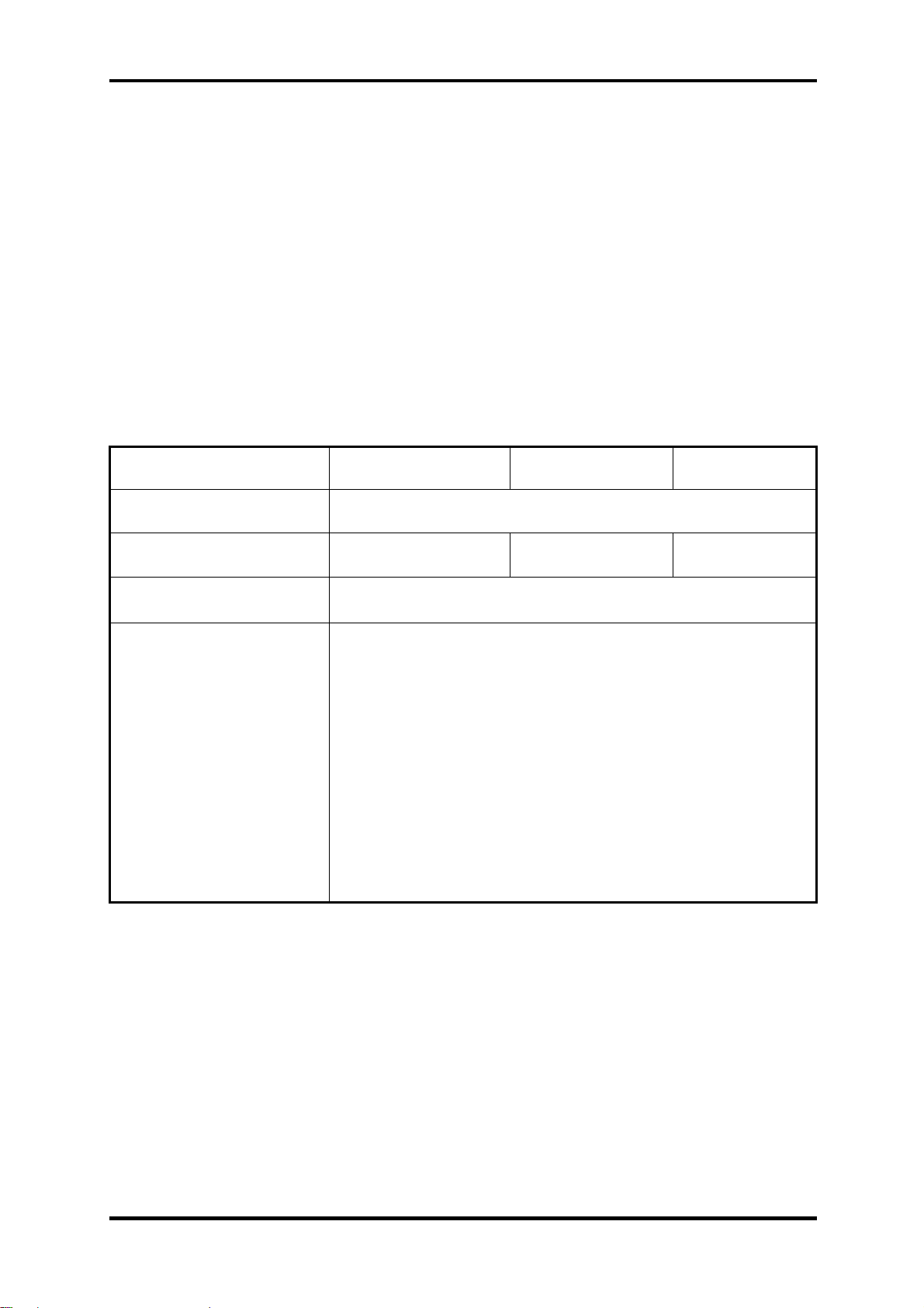
The HDD is shown in Figure 1-1. Specifications are listed in Table 1-1.
Figure 1-1 2.5-inch HDD
Items 60GB 80GB 100GB 120GB
Formatted
capacity (GB)
Logical Blocks
(LBA)
Rotational
speed (rpm)
Toshiba HDD
Buffer (MB)
Hitachi HDD
Buffer (MB)
Fujitsu HDD
Buffer (MB)
55.89 74.52 93.15 111.8
117,210,240 156,301,488 195,371,568 234,441,648
5400 5400 5400 5400
8 8 8 8
8 8 8 8
8 8 8 8
Bytes per sector 512 512 512 512
Table 1-1 2.5-inch HDD specifications
1-6
[CONFIDENTIAL]
Satellite X200/ X205 Series Maintenance Manual
Page 20
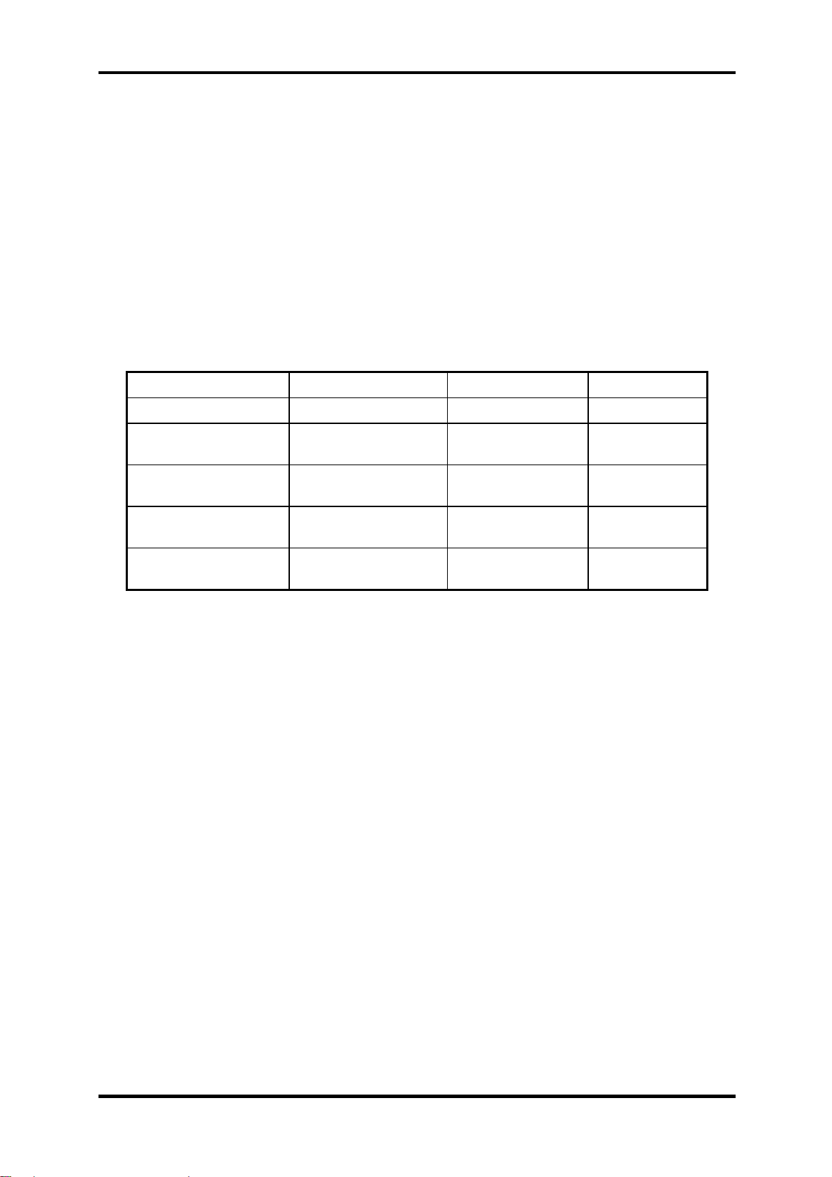
1.3 2.5-inch Hard Disk Drive 1 Hardware Overview
Items 160GB 200GB 250GB 300GB
Formatted
capacity (GB)
Logical Blocks
(LBA)
Rotational
speed (rpm)
Toshiba HDD
Buffer (MB)
Hitachi HDD
Buffer (MB)
Fujitsu HDD
Buffer (MB)
149.05 186.31 232.89 279.46
312,581,808 390,720,968 488,397,168 586,072,368
5400/4200 4200 4200 4200
8 8 N/A N/A
8 N/A N/A N/A
8 8 8 8
Bytes per sector 512 512 512 512
Table 1-1 2.5-inch HDD specifications (Continued)
Satellite X200/ X205 Series Maintenance Manual
[CONFIDENTIAL]
1-7
Page 21
1 Hardware Overview 1.4 Optical Disc Devices
1.4 DVD Super Multi Double Layer
The DVD Super Multi drive accepts 12-cm (4.72-inch) and 8-cm (3.15-inch) discs. At
maximum, the drive can play back a DVD at 8x speed, read CD-ROM at 24x speed, write
CD-R at 24x speed and CD-RW at 4x speed, US CD-RW at 16x speed, High Speed CD-RW
at 10x speed, DVD-R at 8x speed, DVD-RW at 6x speed, DVD+R at 8x speed, DVD+R
(Double Layer) at 4x speed, DVD-R (Double Layer) at 4x speed, DVD+RW at 8x speed and
DVD-RAM at 5x speed.
The specifications of the DVD Super Multi Double Layer drive are listed in Table 1-3.
Item DVD-ROM mode CD-ROM mode
Data transfer rate (Mbytes/s)
Access time (ms)
Average random access
33.3 (U-DMA transfer mode 2)
16.6 (PIO mode 4, Multiword DMA mode 2)
130 130
Data buffer size (Mbytes) 2MB
DVD:
DVD-VIDEO, DVD-ROM, DVD-R, DVD-RW, DVD-RAM,
DVD+R, DVD+RW, DVD+R DL, DVD-R DL
Formats supported
CD:
CD-DA, CD-ROM, CD-R, CD-RW, CD-ROMXA,
Photo CD (single/multi-session), CD-EXTRA, CD-Text
Table 1-2 DVD Super Multi Double Layer drive specifications
1-8
[CONFIDENTIAL]
Satellite X200/ X205 Series Maintenance Manual
Page 22
1.4 Optical Disc Devices 1 Hardware Overview
1.5 HD DVD Drive
1.5.1 HD DVD-ROM
The HD DVD drive accepts 12-cm (4.72-inch) and 8-cm (3.15-inch) discs. At maximum, HD
DVD-ROM reads HD DVD-ROMs at maximum 1x speed DVD-ROMs at maximum 8x
speed and CD-ROMs at maximum 24x speed. It writes CD-R at up to 16x speed, CD-RW at
up to 10x speed, DVD-R at maximum4x speed, DVD-RW at maximum 6x speed, DVD+RW
at maximum 4x speed, DVD+R at maximum 4x speed, DVD+R (double layer) at maximum
2.4x speed, DVD-R (dual layer) at maximum 2x speed and DVD-RAM at maximum 3x speed.
The specifications of the HD DVD-ROM drive are listed in Table 1-3.
Item HD DVD-ROM mode DVD-ROM mode CD-ROM mode
Data transfer rate (Mbytes/s)
Access time (ms)
Average random access
33.3 (U-DMA transfer mode 2)
16.6 (PIO mode 4, Multiword DMA mode 2)
330 160 150
Data buffer size (Mbytes) 8MB
HD DVD:
HD DVD-ROM
DVD:
Formats supported
DVD-VIDEO, DVD-ROM, DVD-R, DVD-RW, DVD-RAM,
DVD+R, DVD+RW, DVD+R DL, DVD-R DL
CD:
CD-DA, CD-ROM, CD-R, CD-RW, CD-ROMXA,
Photo CD (single/multi-session), CD-EXTRA, CD-Text
Table 1-
3
HD DVD-ROM drive specifications
Satellite X200/ X205 Series Maintenance Manual
[CONFIDENTIAL]
1-9
Page 23

1 Hardware Overview 1.5 Power Supply
1.5.2 HD DVD-R
The HD DVD drive accepts 12-cm (4.72-inch) and 8-cm (3.15-inch) discs. At maximum, HD
DVD-R reads HD DVD-ROMs at maximum 1x speed DVD-ROMs at maximum 8x speed
and CD-ROMs at maximum 24x speed. It writes CD-R at up to 16x speed, CD-RW at up to
10x speed, DVD-R at maximum 4x speed, DVD-RW at maximum 4x speed, DVD+RW at
maximum 4x speed, DVD+R at maximum 4x speed, DVD+R (double layer) at maximum
2.4x speed, DVD-R (dual layer) at maximum 2x speed DVD-RAM at maximum 3x speed and
HD DVD-R at maximum 1x speed.
The specifications of the HD DVD-R drive are listed in Table 1-4.
Item HD DVD-ROM mode DVD-ROM mode CD-ROM mode
Data transfer rate (Mbytes/s)
Access time (ms)
Average random access
33.3 (U-DMA transfer mode 2)
16.6 (PIO mode 4, Multiword DMA mode 2)
330 180 190
Data buffer size (Mbytes) 8MB
HD DVD:
HD DVD-ROM, HD DVD-R
DVD:
Formats supported
DVD-VIDEO, DVD-ROM, DVD-R, DVD-RW, DVD-RAM,
DVD+R, DVD+RW, DVD+R DL, DVD-R DL
CD:
CD-DA, CD-ROM, CD-R, CD-RW, CD-ROMXA,
Photo CD (single/multi-session), CD-EXTRA, CD-Text
Table 1-
4
HD DVD-R drive specifications
1-10
[CONFIDENTIAL]
Satellite X200/ X205 Series Maintenance Manual
Page 24

1.5 Power Supply 1 Hardware Overview
1.6 Power Supply
This specification defines the performance and characteristic of 180W AC adapter power
supply. It supplies a constant voltage 19V output source for Satellite X200/ X205 Series
Personal Computer.
A/D conversion
• The EC uses 10-bit sampling for A/D conversion to determine the following
values:
– Battery and temperature
AC adaptor and battery check
• The EC checks the following by A/D converted values:
– Battery installed
• The EC checks the following by GPIO values:
– AC adaptor connected
Abnormal check
• The EC determines whether the condition is abnormal, and if so, stores an error
code into the error register.
Input port management
• The EC monitors the following input signal status:
– System power ON/OFF status
– Direct CD power ON/OFF status
Beep and LED control
• Beep is caused by the low battery status.
• The EC controls the following two kinds of LED
– DC IN LED (one color: red)
• Red: indicates AC adaptor is connected
– Battery LED (two colors: orange and red)
• Red solid: The battery is fully charged.
• Orange: The computer is quick-charging the battery / The battery is low.
Power ON/OFF sequence
• When power is turned on or off, the EC starts the power on or off sequence.
– SQ0-4 = power ON sequence
– SQ5-B = power OFF sequence
Satellite X200/ X205 Series Maintenance Manual
[CONFIDENTIAL]
1-11
Page 25

1 Hardware Overview 1.5 Power Supply
Battery charging control
• The EC controls the following.
– The quick charging ON/OFF
– The detection of full charge
Detection of the low battery
• The EC detects the low battery point by the gas gauge.
– LB10M: The system will be driven by the battery for 12 more minutes.
– LB0: The battery won't be able to drive the system after 3 minutes.
– LB1: The battery can drive the system only during the suspend process.
– LB2: The battery cannot drive the system.
New battery installation
• When a new battery is installed, the EC communicates with the E2PROM in the
battery to read information of the newly installed battery.
Battery capacity calculation
• The EC reads battery remaining and percentage capacity from the battery
through SMBus.
1-12
[CONFIDENTIAL]
Satellite X200/ X205 Series Maintenance Manual
Page 26
1.6 Batteries 1 Hardware Overview
1.7 Batteries
The computer has two types of battery:
Main battery pack (18650 size)
RTC battery
The removable main battery pack is the computer’s main power source when the AC adaptor
is not attached.
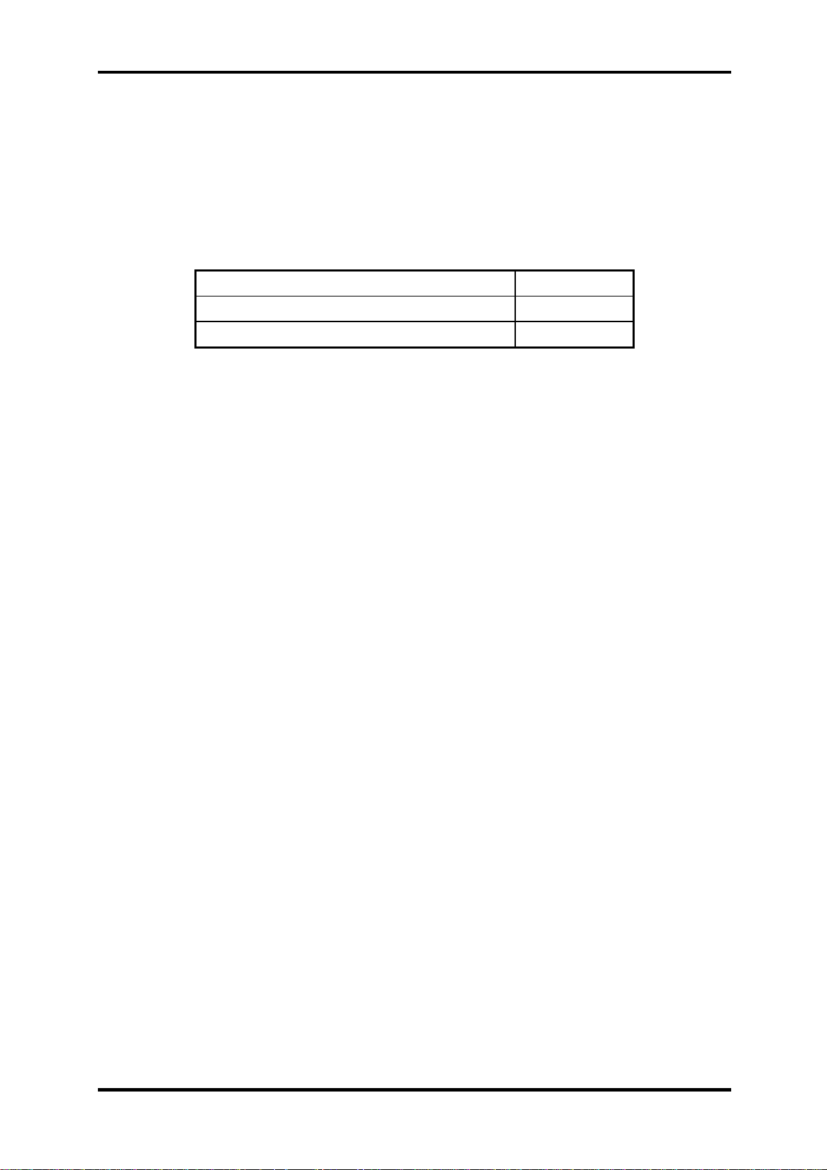
The battery specifications are listed in the table below.
Battery name Material Output voltage Capacity
Main battery (9 cells) Lithium-Ion 10.8V 6000mAH
RTC battery (Maxell
ML1220T10)
RTC battery (Maxell
ML1220HT10)
RTC battery (Sanyo
ML1220T28)
RTC battery (Panasonic
ML1220/B)
Lithium-Ion 3.0V 14 mAH
Lithium-Ion 3.0V 18 mAH
Lithium-Ion 3.0V 15 mAH
Lithium-Ion 3.0V 17 mAh
Table 1-5 Battery specifications
Satellite X200/ X205 Series Maintenance Manual
[CONFIDENTIAL]
1-13
Page 27

1 Hardware Overview 1.6 Batteries
1.7.1 Main Battery
Battery charging is controlled by a power supply microprocessor that is mounted on the
system board. The power supply microprocessor controls whether the charge is on or off and
detects a full charge when the AC adaptor and battery are attached to the computer. The
system charges the battery using quick charge or trickle charge.
Quick battery charge
When the AC adaptor is attached, there are two types of quick charge: quick charge
when the system is powered off and normal charge when the system is powered on.
The times required for charges are listed in the table below.
Status Charging time
Normal charge (power on) 12 hours or longer
Quick charge (power off) About 4 hours or longer
NOTES
1. The time required for normal charge is affected by the amount of power the system
is consuming. Use of the fluorescent lamp and frequent disk access diverts power
and lengthens the charge time.
2. Using quick charge, the power supply microprocessor automatically stops the
charge after eight hours regardless of the condition of the battery. Overcharging
could cause the battery to explode.
If any of the following occurs, the battery quick charge process stops.
1. The battery becomes fully charged.
2. The AC adaptor or battery is removed.
3. The battery or output voltage is abnormal.
4. The battery temperature is abnormal.
5. The battery SMBus communication fails.
6. The battery cell is bad.
Detection of full charge
A full charge is detected from the battery pack through SMBus when the battery is
charging.
1-14
[CONFIDENTIAL]
Satellite X200/ X205 Series Maintenance Manual
Page 28
1.6 Batteries 1 Hardware Overview
1.7.2 RTC battery
The RTC battery provides power to keep the current date, time and other setup information in
memory while the computer is turned off. The table below lists the charging time and data
preservation period of the RTC battery. The RTC battery is charged by the adaptor or main
battery, while the computer is powered on.
Status Time
Charging Time (power on) About 24 hours
Data preservation period (full charge) 1 month
Satellite X200/ X205 Series Maintenance Manual
[CONFIDENTIAL]
1-15
Page 29

Chapter 2
Troubleshooting Procedures
2
Page 30

Page 31

2 Troubleshooting Procedures
Chapter 2 Contents
2.1 Troubleshooting Introduction ........................................................................................3
2.2 Troubleshooting Flowchart............................................................................................4
2.3 Power Supply Troubleshooting......................................................................................9
2.4 Display Troubleshooting.................................................................................……….14
2.5 Keyboard Troubleshooting ..........................................................................................17
2.6 External USB Devices Troubleshooting......................................................................19
2.7 TV-Out Failure Troubleshooting.................................................................................21
2.8 TouchPad Troubleshooting..........................................................................................23
2.9 Speaker Troubleshooting.............................................................................................25
2.10 Optical drive troubleshooting......................................................................................27
2.11 Modem Troubleshooting …………………………………………………………….30
2.12 Express card Troubleshooting......................................................................................32
2.13 IEEE 1394 Troubleshooting ........................................................................................34
2.14 Wireless LAN Troubleshooting...................................................................................36
2.15 Camera troubleshooting...............................................................................................38
2.16 Bluetooth Troubleshooting…………………...…………………………….……….. 40
2.17 4 in 1 card Troubleshooting……………………………………………………..……42
2.18 HDD Troubleshooting………………………………………………………………..44
2.19 CRT failure Troubleshooting ………………………………………………………. 46
2.20 HDMI Troubleshooting ……………………………………………………………...48
2.21 Robson Troubleshooting ……………………………………………………………. 50
2.22 MIC Troubleshooting ………………………………………………………………. 52
2.23 Finger Troubleshooting …………………………………………………………….. 54
Satellite x200/x205/satellite Pro x200 /
EQUIUM X200 /SATEGO X200 Series
Maintenance Manual 1
Page 32

2 Troubleshooting Procedures
Figures
Figure 2-1 Troubleshooting flowchart (1/2) .......................................................................5
Figure 2-1 Troubleshooting flowchart (2/2) .......................................................................6
Figure 2-2 Power Supply Troubleshooting Process............................................................9
Figure 2-3 Display troubleshooting process .....................................................................14
Figure 2-4 Keyboard troubleshooting process .................................................................. 17
Figure 2-5 External USB device troubleshooting process ................................................ 19
Figure 2-6 TV-out troubleshooting process......................................................................21
Figure 2-7 TouchPad troubleshooting process..................................................................23
Figure 2-8 Speaker troubleshooting process.....................................................................25
Figure 2-9 Optical drive troubleshooting process.............................................................27
Figure 2-10 Modem troubleshooting process .....................................................................30
Figure 2-11 Express card troubleshooting process .............................................................32
Figure 2-12 IEEE 1394 troubleshooting process ................................................................ 34
Figure 2-13 Wireless LAN troubleshooting process...........................................................36
Figure 2-14 Camera troubleshooting process .....................................................................38
Figure 2-15 Bluetooth troubleshooting process…..……………………………….………40
Figure 2-16 4 in 1 card troubleshooting process……………………………..…….………42
Figure 2-17 HDD troubleshooting process……………………………….………………..44
Figure 2-18 CRT failure troubleshooting process ………………………………………....46
Figure 2-19 HDMI Troubleshooting process ……………………………………………...48
Figure 2-20 Robson troubleshooting process ……………………………………………..50
Figure 2-21 MIC troubleshooting process ………………………………………………...52
Figure 2-22 Finger printer troubleshooting process ………………………………………54
Tables
Table 2-1 Battery LED .......................................................................................................10
Table 2-2 DC-IN LED........................................................................................................11
Satellite x200/x205/satellite Pro x200 /
EQUIUM X200 /SATEGO X200 Series
Maintenance Manual 2
Page 33

2 Troubleshooting Procedures
2.1 Troubleshooting Introduction
Chapter 2 describes how to determine if a Field Replaceable Unit (FRU) in the computer is
causing the computer to malfunction. The FRUs covered are:
1. Display 7. Speaker 13. Camera
2. USB Floppy Drive 8. Optical drive 14. Bluetooth
3. Keyboard 9. Modem 15 HDMI
4. USB ports 10. Express card unit 16. Robson card
5. TV-out port 11. IEEE 1394 port 17. MIC
6. TouchPad 12. Wireless LAN system 18. Finger
The Diagnostics Disk operations are described in Chapter 3. Detailed replacement
procedures are given in Chapter 4.
The following tools are necessary for implementing the troubleshooting procedures:
1. Diagnostics Disk (Repair and Sound Repair)
2. Phillips screwdriver (2 mm)
3. 6mm nut driver (for the helix screw nuts on the rear ports for CPU door)
4. 2DD or 2HD formatted work disk for floppy disk drive testing
5. Sycard (EXPRESS CARD test card)
6. Cleaning kit for floppy disk drive troubleshooting
7. Cleaning kit for optical drive troubleshooting
8. Multimeter
9. External monitor
10. USB compatible keyboard
11. Multimedia sound system with line-in and line-out ports
12. Headphones
13. USB test module and USB cable
14. Music CD
15. MIC module and MIC line
16. Robson card
17. Finger print module
Satellite x200/x205/satellite Pro x200 /
EQUIUM X200 /SATEGO X200 Series
Maintenance Manual
3
Page 34

2 Troubleshooting Procedures
2.2 Troubleshooting Flowchart
If you know the location of the malfunction, turn directly to the appropriate section of this
chapter. If the problem is unspecified, use the flowchart in Figure 2-1 as a guide for
determining which troubleshooting procedures to execute. Before performing any
troubleshooting procedures, verify the following:
z Ask the user if a password is registered and, if it is, ask him or her to enter the password.
z Verify with the customer that Toshiba Windows Vista is installed on the hard disk.
Operating systems that were not preinstalled by Toshiba can cause the computer to
malfunction.
z Make sure all optional equipment is removed from the computer.
z Make sure the floppy disk drive, if installed, is empty. If no FDD module is installed,
you should use an external FDD to run the diagnostics tests
Satellite x200/x205/satellite Pro x200 /
EQUIUM X200 /SATEGO X200 Series
Maintenance Manual
4
Page 35

2 Troubleshooting Procedures
STAR T
Connect the A C adapter to the DC -IN socket
Is the D C-IN L E D o n ?
Yes
Is the Battery LED on?
Yes
No
No
Perform the Power Supply
Troubleshooting procedures
in section 2.3
Perform the Power Supply
Troubleshooting procedures
in section 2.3
Turn the Power switch on
Yes
Is the P ower On L E D o n ?
Yes
Is the "Toshiba" logo message
display?
Yes
If the "password" m essage
displays, type the passw ord, then
press Enter.
Is T oshiba Window s being
loa d ed ?
Yes
No
No
No
Perform the Power Supply
Troubleshooting procedures
in section 2.3
Perform the P ower Supply
Troubleshooting procedures
in section 2.3
Perform diagnostics
program . Run CM165.EXE
and select the HA R D D ISK
item.
A
Figure 2-1 Troubleshooting flowchart (1/2)
Satellite x200/x205/satellite Pro x200 /
EQUIUM X200 /SATEGO X200 Series
Maintenance Manual
5
Page 36

2 Troubleshooting Procedures
A
Does typed characters appear correctly?
Yes
Insert the diagnostics disk into the FDD.
Then run the diagnostics test program.
Yes
No
Perform the Keyboard
Troubleshooting procedures
in section 2.6
Is the diagnostics test loaded?
Yes
Allow each test to perform
automatically
Is an error detected by any of the
diagnostics tests?
No
System is normal
No
Yes
Perform the FDD
Troubleshooting procedures
in section 2.5
After confirming which
diagnostics test has detected
an error, perform the
appropriate procedure as
outlined below.
End
Figure 2-1 Troubleshooting flowchart (2/2)
Satellite x200/x205/satellite Pro x200 /
EQUIUM X200 /SATEGO X200 Series
Maintenance Manual
6
Page 37

2 Troubleshooting Procedures
If the diagnostics program cannot detect an error, the problem may be intermittent. The test
program should be executed several times to isolate the problem. When a problem has been
located, perform the appropriate troubleshooting procedures as follows:
1. If an error is detected by the battery test, perform the Power Supply Troubleshooting
procedures in Section 2.3.
2. If an error is detected by the display test, perform the Display Troubleshooting
procedures in Section 2.4.
3. If an error is detected by the keyboard test, perform the Keyboard Troubleshooting
procedures in Section 2.5.
4. If an error is detected by the TouchPad test, perform the TouchPad Troubleshooting
procedures in Section 2.8.
5. If an error is detected by the audio test, perform the Speaker Troubleshooting
procedures in Section 2.9 and the Optical Drive Troubleshooting Procedures in
Section 2.10.
6. If an error is detected by the modem test, perform the Modem Troubleshooting
Procedures in Section 2.11.
Satellite x200/x205/satellite Pro x200 /
EQUIUM X200 /SATEGO X200 Series
Maintenance Manual
7
Page 38

2 Troubleshooting Procedures
Other problems that are not covered by the diagnostics program may be discovered by a
user.
1. If an error is detected when using an external USB device, perform the External USB
Devices Troubleshooting procedures in Section 2.6.
2. If an error is detected when using the TV-out connection, perform the TV-Out Failure
Troubleshooting procedures in Section 2.7.
3. If an error is detected when using the speakers, perform the Speaker Troubleshooting
procedures in Section 2.10.
4. If an error is detected when using the modem, perform the Modem Troubleshooting
procedures in Section 2.11.
5. If an error is detected when using the EXPRESS CARD unit, perform the EXPRESS
CARD Troubleshooting procedures in Section 2.12.
6. If an error is detected when using the IEEE1394 device, perform the IEEE1394 device
Troubleshooting procedures in Section 2.13.
7. If an error is detected when using the Wireless LAN, perform the Wireless LAN
Troubleshooting procedures in Section 2.14.
Satellite x200/x205/satellite Pro x200 /
EQUIUM X200 /SATEGO X200 Series
Maintenance Manual
8
Page 39

2 Troubleshooting Procedures
2.3 Power Supply Troubleshooting
START
Check Power Supp ly Status
(Procedure 1)
Are the DC-IN and
Ba tte ry L ED s lit?
Yes
Check power supply
connections
(Procedure 3)
Can you turn the
computer on?
No
Are th e in te rn a l p o w er
connections secure?
No
Yes
No
Replace adaptor / battery
(Procedure 2)
Run diagnostic program
(Procedure 4)
Pe rfo rm inter n al c o n ne c tio n
check
(Procedure 5)
Yes
Replace system board
END
Figure 2-2 Power Supply Troubleshooting Process
Satellite x200/x205/satellite Pro x200 /
EQUIUM X200 /SATEGO X200 Series
Maintenance Manual
9
Page 40

2 Troubleshooting Procedures
The power supply controls many functions and components. To determine if the power
supply is functioning properly, start with Procedure 1 and continue with the other Procedures
as instructed. The flowchart in Figure 2-2 gives a summary of the process. The procedures
described in this section are:
Procedure 1: Power status check
Procedure 2: Adaptor / battery replacement
Procedure 3: Power supply connection check
Procedure 4: Diagnostic check
Procedure 5: Internal connection check
Procedure 1 Power Status Check
The following LEDS indicate the power supply status:
Battery LED
DC-IN LED
The power supply controller displays the power supply status through the Battery and the DCIN LEDS as listed in the tables below.
Table 2-1 Battery LED
Battery State LED colors Definition
Charging
Amber, solid on Battery charging with AC.
Blue, solid on Battery fully charged by AC
Blue color off Battery abnormal stop charging with AC
(Bad cell/ Overheated)
Discharging
Amber, blinking
(LED on for 1 second
Battery within low state: 12 minutes
remaining
every 4 seconds)
Amber, blinking
(LED on for 1 second
every 2 seconds)
Battery within critical low state: 3
minutes remaining. The system is
protected and cannot be re-powered on
without the AC power connected.
Amber color off Battery not in low or critical low state;
Satellite x200/x205/satellite Pro x200 /
It’s in discharging state
EQUIUM X200 /SATEGO X200 Series
Maintenance Manual
10
Page 41

2 Troubleshooting Procedures
Table 2-2 DC-IN LED
AC-IN LED Power supply status
Solid on AC power exists (LED is solid Blue).
Off No AC power exists.
To check the power supply status, install a battery pack and connect an AC adaptor to the
DC-IN port on the computer and to a power supply.
If the DC-IN LED or Battery LED is not lit, go to Procedure 2.
Procedure 2 Adaptor / battery replacement
A faulty adaptor may not supply power or may not charge the battery. Perform Check 1.
Check 1 Connect a new AC adaptor. If the problem is not resolved, go to Check 2.
Check 2 Insert a new battery. If the problem is still not resolved, go to Procedure 3.
Satellite x200/x205/satellite Pro x200 /
EQUIUM X200 /SATEGO X200 Series
Maintenance Manual
11
Page 42

2 Troubleshooting Procedures
Procedure 3 Power supply connection check
The power supply wiring diagram is shown below:
A C ad aptor cord
AC power cord
AC
adaptor
System
board
B a tter y
Any of the connectors may be disconnected. Perform Check 1.
Check 1 Disconnect the AC power cord from wall outlet. Check the power cable for
breaks. If the power cord is damaged, connect a new AC power cord. If there is
no damage, go to Check 2.
Check 2 Make sure the AC adaptor cord and AC power cord are firmly plugged into the
DC-IN socket, AC adaptor inlet and wall outlet. If these cables are connected
correctly, go to Check 3.
Check 3 Make sure that the DC-IN input port socket is firmly secured to the system board
of the computer.
• If the DC-IN input socket is loose, go to Procedure 5.
• If it is not loose, go to Check 4.
Check 4 Use a multi-meter to make sure that the AC adaptor output voltage is close to 19
V. If the output is several percent lower than 19 V, go to Check 5. If the output
is close to 19 V, go to Check 6.
Check 5 Connect a new AC adaptor or AC power cord.
• If the DC-IN LED does not light, go to Procedure 4.
• If the battery LED does not light, go to Check 6.
Check 6 Make sure the battery pack is installed in the computer correctly. If the battery is
properly installed and the battery LED still does not light, go to Procedure 4.
Satellite x200/x205/satellite Pro x200 /
EQUIUM X200 /SATEGO X200 Series
Maintenance Manual
12
Page 43

2 Troubleshooting Procedures
Procedure 4 Diagnostic check
The power supply may not charge the battery pack. Perform the following procedures:
1. Reinstall the battery pack.
2. Attach the AC adaptor and turn on the power. If you cannot turn on the power, go to
Procedure 5.
3. Run the Diagnostic test following the procedures described in Chapter 3, Tests and
Diagnostics. If no problem is detected, the battery is functioning normally.
Procedure 5 Replacement check
The system board may be disconnected or damaged. Disassemble the computer following the
steps described in Chapter 4, Replacement Procedures. Check the connection between the AC
adaptor and the system board. After checking the connection, perform Check 1:
Check 1 Use a multi-meter to make sure that the fuses on the system board are not blown.
If a fuse is not blown, go to Check 2. If a fuse is blown, go to Check 3.
Check 2 Make sure that the battery cable is firmly connected to the system board. If it is
connected firmly, go to Check 3.
Check 3 The system board may be damaged. Replace it with a new one following the
instructions in Chapter 4.
Satellite x200/x205/satellite Pro x200 /
EQUIUM X200 /SATEGO X200 Series
Maintenance Manual
13
Page 44

2 Troubleshooting Procedures
2.4 Display Troubleshooting
STAR T
Perform external display check
(Pro c ed u re 1 )
D oes the external
display function ok?
No
Yes
Perform diagnostic check
(Pro c ed u re 2 )
Was a display
problem detected?
Yes
Perform connector and
replacemen t check
(Pro c ed u re 3 )
Replace system board
END
No
D is p lay is n o t
faulty. Continue
troubleshooting-
refer to F igu re 2 .1
Figure 2-3 Display troubleshooting process
Satellite x200/x205/satellite Pro x200 /
EQUIUM X200 /SATEGO X200 Series
Maintenance Manual
14
Page 45

2 Troubleshooting Procedures
This section describes how to determine if the computer’s display is functioning properly.
The process is outlined in Figure 2-3. Start with Procedure 1 and continue with the other
procedures as instructed.
Procedure 1: External display check
Procedure 2: Diagnostic check
Procedure 3: Connector and replacement check
Procedure 1 External display check
Connect an external display to the computer’s external monitor port, and then boot the
computer. The computer automatically detects the external display.
If the external display works correctly, the internal LCD may be damaged. Go to Procedure 3.
If the external monitor appears to have the same problem as the internal monitor, the system
board may be damaged. Go to Procedure 2.
Procedure 2 Diagnostic check
The Display Test program is stored on the computer’s Diagnostics disk. This program checks
the display controller on the system board. Insert the Diagnostics disk in the computer’s
floppy disk drive, turn on the computer and run the test. Refer to Chapter 3, Tests and
Diagnostics for details.
If an error is detected, go to Procedure 3. If an error is not detected, the display is functioning
properly.
Satellite x200/x205/satellite Pro x200 /
EQUIUM X200 /SATEGO X200 Series
Maintenance Manual
15
Page 46

2 Troubleshooting Procedures
Procedure 3 Connector and replacement check
The FL inverter board, LCD module, and system board are connected to the display circuits.
Any of these components may be damaged. Refer to Chapter 4, Replacement Procedures, for
instructions on how to disassemble the computer and then perform the following checks:
Check 1 Make sure the DDR RAM module is seated properly. Test display again. If the
problem still exits, replace the DDR RAM module. If the problem still exists,
perform Check 2.
Check 2 Replace the FL inverter board with a new one and test display again. If the
problem still exists, perform Check 3.
Check 3 Replace the LCD module with a new one and test display again. If the problem
still exists, perform Check 4.
Check 4 Replace the LCD/FL cable with a new one and test display again. If the problem
still exists, perform Check 5.
Check 5 Replace the CPU with another of the same specifications. If the problem still
exists, perform Check 6.
Check 6 The system board may be damaged. Replace it with a new one.
Satellite x200/x205/satellite Pro x200 /
EQUIUM X200 /SATEGO X200 Series
Maintenance Manual
16
Page 47

2 Troubleshooting Procedures
2.5 Keyboard Troubleshooting
STAR T
No
Perform external keyboard check
Perform diagnostic check
(Procedure 1)
D oes the external
keyboard function ok?
Yes
(Procedure 2)
W as a keyboard
problem detected?
Yes
No
Keyboard is not
faulty. Continue
troubleshooting-refer
to Figure 2.1
Pe rform con n ec tor an d
replacement check
(Procedure 3)
Rep lace system bo ard
Figure 2-4 Keyboard troubleshooting process
Satellite x200/x205/satellite Pro x200 /
END
EQUIUM X200 /SATEGO X200 Series
Maintenance Manual
17
Page 48

2 Troubleshooting Procedures
To determine if the computer’s keyboard is functioning properly, perform the following
procedures. Figure 2-5 outlines the process. Start with Procedure 1 and continue with the
other procedures as instructed.
Procedure 1: External keyboard check
Procedure 2: Diagnostic check
Procedure 3: Connector and replacement check
Procedure 1 External keyboard check
Connect a USB keyboard to one of the computer’s USB ports, and then boot the computer.
The computer automatically detects the external keyboard.
If the external keyboard works correctly, the internal keyboard or its connections may be
faulty. Go to Procedure 2.
If the external keyboard appears to have the same problem as the internal keyboard, the
system board may be having some problem. Replace it with a new one and following the
instructions in Chapter 4.
Procedure 2 Diagnostic check
Run the test and Diagnostics Program, which will automatically execute the Keyboard Test.
Refer to Chapter 3, Tests and Diagnostics for more information on how to run the program.
If an error is located, go to Procedure 3. If an error does not occur, the keyboard is
functioning ok.
Procedure 3 Connector and replacement check
The keyboard and/or system board may be disconnected or damaged. Disassemble the
computer following the steps described in Chapter 4, Replacement Procedures and perform
the following checks.
Check 1 Make sure the keyboard cable is firmly connected to the system board.
If the connection is loose, reconnect firmly and repeat Procedure 2. If there is still
an error, go to Check 2.
Check 2 The keyboard may be damaged. Replace it with a new one following the
instructions in Chapter 4.
If the problem still exists, perform Check 3.
Check 3 The system board may be damaged. Replace it with a new one following the
instructions in Chapter 4.
Satellite x200/x205/satellite Pro x200 /
EQUIUM X200 /SATEGO X200 Series
Maintenance Manual
18
Page 49

2 Troubleshooting Procedures
2.6 External USB Devices Troubleshooting
STAR T
Perform external device and
connection check
(Procedure 1)
Ch eck U SB
port
connection
Do es the device function
Yes
when connected to a
differe nt U S B p ort?
D o e s an alte rn a tiv e U S B
device function correctly?
Replace system board
(Procedure 2)
No
No
END
O r ig in al U SB
Yes
de v ic e is f au lty
Figure 2-5 External USB device troubleshooting process
Satellite x200/x205/satellite Pro x200 /
EQUIUM X200 /SATEGO X200 Series
Maintenance Manual
19
Page 50

2 Troubleshooting Procedures
To determine if the computer’s external USB devices are functioning properly, perform the
following procedures. Figure 2-6 outlines the process. Start with Procedure 1 and continue as
instructed.
Procedure 1: External device and connection check
Procedure 2: Replace system board
Procedure 1 External device and connection check
The USB device may be damaged or the connection may be faulty. Perform Check 1.
Check 1 Make sure USB device cable is firmly plugged into one of the USB sockets. If the
cable is connected correctly, go to Check 2.
Check 2 Plug the USB device into another USB socket (there are three in all). If the USB
device still does not work, go to Check 4.
If the device functions correctly when connected to another USB port, go to
Check 3.
Check 3 Make sure that the USB socket is firmly secured to the system board of the
computer. If the malfunction remains, the system board may be damaged. Go to
Procedure 2.
Check 4 Connect an alternative USB device to one of the computer’s USB ports, and then
boot the computer. The computer automatically detects the external device.
If the alternative USB device works correctly, the original device may be
damaged and should be replaced.
If the alternative USB device appears to have the same problem as the original
device, the system board may be damaged. Go to Procedure 2.
Procedure 2 Replace system board
If the error persists, the system board may be damaged. Replace it with a new one following
the instructions in Chapter 4.
Satellite x200/x205/satellite Pro x200 /
EQUIUM X200 /SATEGO X200 Series
Maintenance Manual
20
Page 51

2 Troubleshooting Procedures
2.7 TV-Out Failure Troubleshooting
STAR T
Perform T V connection check
(Pro c ed u re 1 )
D oes replacem en t TV cab le
function properly?
No
Perform TV set check
(Pro c ed u re 2 )
TV functioning ok?
Yes
Re place system bo ard
No
No
Rep lace TV
cable
U se different
TV set
END
Figure 2-6 TV-out troubleshooting process
Satellite x200/x205/satellite Pro x200 /
EQUIUM X200 /SATEGO X200 Series
Maintenance Manual
21
Page 52

2 Troubleshooting Procedures
To determine if the computer’s TV-out port is functioning properly, perform the following
procedures. Figure 2-7 outlines the process. Start with Procedure 1 and continue as instructed.
Procedure 1: TV connection check
Procedure 2: TV set check
Procedure 1 TV connection check
The TV cable may be damaged or the connections may be loose. Perform Check 1:
Check 1 Make sure TV cable is firmly plugged into both the TV set and the TV-out port of
the computer. If the cable is connected correctly, go to Check 2.
Check 2 Make sure the TV-out port is firmly secured to the system board of the computer.
If the malfunction remains, go to Check 3.
Check 3 The TV cable may be damaged. Replace with a good cable. If the malfunction
remains, go to Procedure 2.
Procedure 2 TV set check
The TV set may be faulty. Perform Check 1:
Check 1 Try using the set for television reception. If it does not work, the set may be
damaged. If the set does work, perform Check 2.
Check 2 Try connecting a different television to the computer. If the replacement
television works, the original set may be damaged. If the replacement set does not
work the system board may be damaged. Replace it with a new one following the
instructions in Chapter 4.
Satellite x200/x205/satellite Pro x200 /
EQUIUM X200 /SATEGO X200 Series
Maintenance Manual
22
Page 53

2 Troubleshooting Procedures
2.8 TouchPad Troubleshooting
START
TouchP ad connection
check (Procedure 1)
TouchPad replacement
check (Procedure 2)
Replace system board
END
Figure 2-7 Touchpad troubleshooting process
Satellite x200/x205/satellite Pro x200 /
EQUIUM X200 /SATEGO X200 Series
Maintenance Manual
23
Page 54

2 Troubleshooting Procedures
To determine if the computer’s built-in TouchPad is functioning properly, perform the
following procedures. Figure 2-9 outlines the process. Start with Procedure 1 and continue as
instructed.
Procedure 1: TouchPad connection check
Procedure 2: TouchPad replacement check
Procedure 1 TouchPad connection check
The TouchPad is connected via the TouchPad FPC to the system board. Make sure the
TouchPad FPC cable is firmly connected to the TouchPad and system board. Refer to Chapter
4, Replacement Procedures, for instructions on how to disassemble the computer and then
perform the following checks.
If any of the connections are loose, reconnect firmly. If any of the connections is damaged, or
there is still an error, go to Procedure 2.
Procedure 2 TouchPad replacement check
The TouchPad unit or FPC may be defective or damaged. Replace each with a new one
following the steps in Chapter 4. If the FDD is still not functioning properly, replace the
system board with a new one following the steps in Chapter 4.
Satellite x200/x205/satellite Pro x200 /
EQUIUM X200 /SATEGO X200 Series
Maintenance Manual
24
Page 55

2 Troubleshooting Procedures
2.9 Speaker Troubleshooting
START
Perform audio source test
(Procedure 1)
Do all sources have
same problem?
Yes
Perform earphone test
(Procedure 2)
No
Speakers are not
faulty. Continue
troubleshooting -
see Figure 2-1
No
Do earphones
function correctly?
Yes
Perform connection check
(Procedure 3)
Perform replacement
check
(Procedure 4)
Replace system board
END
Figure 2-8 Speaker troubleshooting process
Satellite x200/x205/satellite Pro x200 /
EQUIUM X200 /SATEGO X200 Series
Maintenance Manual
25
Page 56

2 Troubleshooting Procedures
To determine if the computer’s built-in speakers are functioning properly, perform the
following procedures. Figure 2-10 outlines the process. First adjust the speaker volume to an
appropriate level. Start with Procedure 1 and continue as instructed.
Procedure 1: Audio source test
Procedure 2: Earphone test
Procedure 3: Connection check
Procedure 4: Replacement check
Procedure 1 Audio source test
Try different audio sources (e.g. an audio CD and digital music file) to determine whether the
fault is in the speaker system or not. If not all sources have sound problem, the problem is in
the source devices. If all have the same problem, continue with Procedure 2.
Procedure 2 Earphone test
Connect a set if earphones or external speakers. If these function correctly, go to Procedure 3.
If they do not function correctly, the system board may be defective or damaged. Replace it
with a new one.
Procedure 3 Connection check
Disassemble the computer following the steps described in Chapter 4, Replacement
Procedures and make sure the speaker cable is firmly connected to the audio board. If the
stereo speakers are still not functioning properly, go to Procedure 4.
Procedure 4 Replacement check
If the stereo speakers don't sound properly, the stereo speakers may be defective or damaged.
Replace them with new ones. If the stereo speakers still do not work properly, try replacing in
turn the audio board and system board.
Satellite x200/x205/satellite Pro x200 /
EQUIUM X200 /SATEGO X200 Series
Maintenance Manual
26
Page 57

2 Troubleshooting Procedures
2.10 Optical Drive Troubleshooting
START
Perform audio CD check
(Procedure 1)
Audio CD functions ok?
No
Perform drivecleaning check
(Procedure 2)
Yes
Perform software check
(Procedure 3)
Perform diagnostic test
(Procedure 4)
Perform connection and
replacement check
(Procedure 5)
Replace system board
END
Figure 2-9 Optical drive troubleshooting process
Satellite x200/x205/satellite Pro x200 /
EQUIUM X200 /SATEGO X200 Series
Maintenance Manual
27
Page 58

2 Troubleshooting Procedures
This section describes how to determine if the computer’s internal optical drive is functioning
properly. The Satellite X200 / X205 / Satellite Pro X200 / EQUIUM X200 /SATEGO X200
Series Maintenance Manual module bays can accommodate the following optical drives:
DVD SuperMulti supporting +-R Double Rayer
Figure 2-11 outlines the process. Perform the steps below starting with Procedure 1 and
continue with the other procedures as required.
Procedure 1: Audio CD test
Procedure 2: Drive cleaning check
Procedure 3: Software check
Procedure 4: Diagnostic test
Procedure 5: Connection and replacement check
Procedure 1 Audio CD check
First, insert an audio CD into the CD/DVD drive. If it works, the problem is not with the
drive. Go to Procedure 3. If the audio CD does not work, go to Procedure 2. If the CD/DVD
LED on the front panel does not light when the disc is played and the drive gives no response,
go straight to Procedure 3.
Procedure 2 Drive cleaning check
Insert a CD/DVD drive-cleaning disk into the drive clean according to the drive-cleaning
product instructions. If the problem persists, go to Procedure 3.
Procedure 3 Software check
Ensure that the appropriate driver has been installed on the computer for the CD/DVD drive.
Procedure 4 Diagnostic test
The audio test program stored in the Diagnostics Disk will test the drive’s ability to play an
audio CD. See Chapter 3 for details.
If any errors occur while executing the diagnostic program, go to Procedure 5.
Satellite x200/x205/satellite Pro x200 /
EQUIUM X200 /SATEGO X200 Series
Maintenance Manual
28
Page 59

2 Troubleshooting Procedures
Procedure 5 Connection check and replacement check
The optical drive connects to the system board. The drive may be disconnected, or the drive
or system board may be damaged. Disassemble the computer following the steps described in
Chapter 4, Replacement Procedures, and perform the following checks:
Check 1 Make sure the drive is firmly connected to the system board. If the connection is
good and there is still an error, go to Check 2.
Check 2 The drive or drive cable may be defective or damaged. Replace each with a new
one following the steps in Chapter 4, Replacement Procedures. If the drive is still
not functioning properly, perform Check 3.
Check 3 The system board may be damaged. Replace it with new one following the
instructions in Chapter 4, Replacement Procedures.
Satellite x200/x205/satellite Pro x200 /
EQUIUM X200 /SATEGO X200 Series
Maintenance Manual
29
Page 60

302 Troubleshooting Procedures
2.11 Modem Troubleshooting
START
Perform telephone line
connection check
(Procedure 1)
Computer unable to
detect telephone signal?
No
Perform connection check
(Procedure 2)
Perform replacement
check
(Procedure 3)
Replace system board
Yes
Check / replace
telephone line and
connections
END
Figure 2-10 Modem troubleshooting process
Satellite x200/x205/satellite Pro x200 /
EQUIUM X200 /SATEGO X200 Series
Maintenance Manual
30
Page 61

312 Troubleshooting Procedures
This section describes how to determine if the computer's modem is functioning properly.
Figure 2-12 outlines the process. Perform the steps below starting with Procedure 1 and
continuing with the other procedures as required.
Procedure 1: Telephone line connection check
Procedure 2: Modem card connection check
Procedure 3: Modem card replacement check
Procedure 1 Telephone line connection check
The telephone cable may be damaged or the connections may be loose. Attempt to connect
the computer to a network through using the modem. If the modem does not function at all,
go to Procedure 3. If the attempt fails because the computer detects no telephone signal, the
fault may be in the telephone cable, the wall socket or the modem port. Perform Check 1:
Check 1 Make sure telephone cable is firmly plugged into both the telephone wall socket
and the modem port of the computer. If the cable is connected correctly, go to
Check 2.
Check 2 Make sure the modem port is firmly secured to the system board of the computer.
If the malfunction remains, go to Check 3.
Check 3 The telephone cable may be damaged. Replace with a good cable. If the
malfunction remains, go to Procedure 2.
Procedure 2 Modem card connection check
Disassemble the computer following the steps described in Chapter 4, Replacement
Procedures and ensure that the modem card is well connected to the system board. If the
problem persists, perform Procedure 3.
Procedure 3 Modem replacement check
The modem card or RJ-11 jack may be faulty. Try replacing them. If the problem persists, the
system board may be defective or damaged. Replace the System Board with a new one
following the steps in Chapter 4, Replacement Procedures.
Satellite x200/x205/satellite Pro x200 /
EQUIUM X200 /SATEGO X200 Series
Maintenance Manual
31
Page 62

322 Troubleshooting Procedures
2.12 Express card Troubleshooting
START
Perform Express card test
(Procedure 1)
Do errors occur during
Ex press c ard test?
Yes
Perform Express card socket
replacement check
(Procedure 2)
Rep lace system bo ard
END
No
Express card unit
is n o t fa u lty .
Figure 2-11 Express card troubleshooting process
Satellite x200/x205/satellite Pro x200 /
EQUIUM X200 /SATEGO X200 Series
Maintenance Manual
32
Page 63

332 Troubleshooting Procedures
This section describes how to determine if the Express card player is functioning properly.
The process is summarized in Figure 2-13. Perform the steps below starting with Procedure 1
and continuing with the other procedures as required.
Procedure 1: Express card test
Procedure 2: Express card socket replacement check
Procedure 1 Express card test
The Express test card contains a Express test program. Ensure the card in fully inserted into
the socket before running the program.
If an error occurs during the Express card test, perform Procedure 2. If no error occurs, it is
likely that the original PC card was faulty.
Procedure 2 Express card socket replacement check
The Express card socket may be damaged or defective, for instance the socket pins can be
bent. Disassemble the computer following the steps described in Chapter 4, Replacement
Procedures and replace the socket. If the problem persists, the system board may be defective
or damaged. Replace the system board with a new one following the steps in Chapter 4.
Satellite x200/x205/satellite Pro x200 /
EQUIUM X200 /SATEGO X200 Series
Maintenance Manual
33
Page 64

342 Troubleshooting Procedures
2.13 IEEE 1394 Troubleshooting
START
Perform IEEE 1394 device check
(Proced ure 1)
Is IEEE 1394 transmission ok?
Yes
No
Perform diagnostic check
(Proced ure 2)
Was an IEEE 1394 problem detected?
Yes
Perform connection and replacement check
(Proced ure 3)
Replace system board
IEEE 1394 port and
transmission are not
No
faulty . C o ntin u e
troubleshooting - refer
to Figure 2.1
END
Figure 2-12 IEEE 1394 troubleshooting process
To determine if the computer’s IEEE 1394 system is functioning properly, perform the
following procedures. Figure 2-14 outlines the process. Start with Procedure 1 and continue
with the other procedures as instructed.
Satellite x200/x205/satellite Pro x200 /
EQUIUM X200 /SATEGO X200 Series
Maintenance Manual
34
Page 65

352 Troubleshooting Procedures
Procedure 1: IEEE 1394 device check
Procedure 2: Diagnostic check
Procedure 3: Connection and replacement check
Procedure 1 IEEE 1394 device check
Connect an IEEE 1394 device to the computer’s IEEE 1394 port, then boot the computer for
Windows Vista. The computer should automatically detect the 1394 device. Check whether
the device can transmit data to the computer.
If the device is able to communicate with the computer, the problem may be intermittent or
connections may be faulty. Go to Procedure 2.
If communication is impaired, there may be a faulty connection. Go to Procedure 3.
Procedure 2 Diagnostic check
Run the Diagnostic Program, which will automatically execute the IEEE 1394 port test for
transmission. Refer to Chapter 3, Tests and Diagnostics for more information on how to run
the program.
If an error is located, go to Procedure 3. If an error does not occur, the 1394 port is
functioning properly.
Procedure 3 Connection and replacement check
The transmission cable may be damaged or the connections may be loose. Perform Check 1:
Check 1 Make sure the transmission cable is firmly plugged into both the IEEE 1394-
compatible device and the IEEE 1394 port of the computer. If the cable is
connected correctly, go to Check 2.
Check 2 Make sure the IEEE 1394 port is firmly secured to the system board of the
computer. If the malfunction persists, go to Check 3.
Check 3 The transmission cable may be damaged. Replace with a good cable. If the
malfunction persists, go to Check 4
Check 4 The system board may be damaged. Replace it with a new one following the
instructions in Chapter 4.
Satellite x200/x205/satellite Pro x200 /
EQUIUM X200 /SATEGO X200 Series
Maintenance Manual
35
Page 66

362 Troubleshooting Procedures
2.14 Wireless LAN Troubleshooting
START
Perform diag n ostic test
(Procedu re 1 )
Was a wireless LAN problem delected?
No
Wireless L A N system
is not f au lty. Con tin u e
troubleshooting - refe r
to Fig u re 2 .1
Yes
Perform co nn ecto r and rep lace m e nt ch ec k
(Procedu re 2 )
Replace wireless LAN antenna/unit
Replace system board
END
Figure 2-13 Wireless LAN troubleshooting process
The wireless LAN antenna wire, wireless LAN unit or system board may each be the source
of a wireless LAN fault. Any of these components may be damaged. To determine if the
Satellite x200/x205/satellite Pro x200 /
EQUIUM X200 /SATEGO X200 Series
Maintenance Manual
36
Page 67

372 Troubleshooting Procedures
computer’s wireless LAN system is functioning properly, perform the following procedures.
Figure 2-15 outlines the process. Start with Procedure 1 and continue with the other
procedures as instructed.
Procedure 1: Diagnostic test
Procedure 2: Connector and replacement check
Procedure 1 Diagnostic test
Run the Diagnostic Program, which will automatically execute the wireless LAN test. Refer
to Chapter 3, Tests and Diagnostics for more information on the program.
If an error is located, go to Procedure 2. If an error is not located, the wireless LAN system is
functioning properly.
Procedure 2 Connector and replacement check
The wireless LAN antenna, wireless LAN unit or system board may be disconnected or
damaged. Disassemble the computer following the steps described in Chapter 4, Replacement
Procedures, and perform the following checks.
Check 1 Make sure that the wireless LAN antenna is firmly connected to the wireless LAN
unit (refer to Chapter 4 for instructions) and that the wireless LAN unit is securely
slotted into the system board. If the problem persists, go to Check 2.
Check 2 Check that the wireless communication switch is turned to “On”, and then make
sure that the wireless communication LED on the front panel is lit. If the LED is
lit but the wireless LAN function is still faulty, the antenna may be damaged.
Replace with a new antenna following the steps in Chapter 4, Replacement
Procedures. If the problem persists, or if the wireless LAN LED is not lit when
the wireless communication switch is turned to “On”, go to Check 3.
Check 3 The wireless LAN unit may be damaged. Replace it with a new one following the
instructions in Chapter 4. If the problem still exists, perform Check 4.
Check 4 The system board may be damaged. Replace it with a new one following the
instructions in Chapter 4.
Satellite x200/x205/satellite Pro x200 /
EQUIUM X200 /SATEGO X200 Series
Maintenance Manual
37
Page 68

382 Troubleshooting Procedures
2.15 Camera Troubleshooting
Figure 2-14 Camera troubleshooting process
The Camera board or system board may be the reason of a Camera fault. Either of these two
components may be damaged. To determine if the computer’s Camera is functioning
Satellite x200/x205/satellite Pro x200 /
EQUIUM X200 /SATEGO X200 Series
Maintenance Manual
38
Page 69

392 Troubleshooting Procedures
properly, perform the following procedures. Figure 2-14 outlines the process. Start with
Procedure 1 and continue with the other procedures as instructed.
Procedure 1: Diagnostic test
Procedure 2: Connector and replacement check
Procedure 1 Diagnostic test
Run the functioning Program in windows, which will display the Camera test result.
If tests and diagnostics result abnormal go to Procedure 2. If an error is not located, the
Camera system is functioning properly.
Procedure 2 Connector and replacement check
The Camera board or system board may be disconnected or damaged. Disassemble the
computer following the steps described in Chapter 4, Replacement Procedures, and perform
the following checks.
Check 1 Make sure that the Camera board FFC is securely slotted into the system board. If
the problem persists, go to Check 2.
Check 2 The Camera board may be damaged. Replace it with a new one following the
instructions in Chapter 4. If the problem still exists, perform Check 3.
Check 3 The system board may be damaged. Replace it with a new one following the
instructions in Chapter 4.
Satellite x200/x205/satellite Pro x200 /
EQUIUM X200 /SATEGO X200 Series
Maintenance Manual
39
Page 70

402 Troubleshooting Procedures
2.16 Bluetooth Troubleshooting
ST A R T
Pr eform di agnost i c t est
( Proc edur e 1)
Was a Bl uetoot h probl em
detect ?
Per form connect or and
r epl acemen t c hec k
( Proc edur e 2)
Repl ace B l uet ooth
antenna moudl e.
Repl ac e sy st em bo ar d
Bl uetoot h i s not f aul t y.
Conti nue tr oubl eshoot i ng-r ef er
t o Fi gur e 2.1
Figure 2-15 Bluetooth troubleshooting process
Satellite x200/x205/satellite Pro x200 /
END
EQUIUM X200 /SATEGO X200 Series
Maintenance Manual
40
Page 71

412 Troubleshooting Procedures
The Bluetooth antenna wire, Bluetooth module or system board may be the reason of a
Bluetooth fault. Any of these components may be damaged. To determine if the computer’s
Bluetooth is functioning properly, perform the following procedures. Figure 2-16 outlines the
process. Start with Procedure 1 and continue with the other procedures as instructed.
Procedure 1: Diagnostic test
Procedure 2: Connector and replacement check
Procedure 1 Diagnostic test
Run the Diagnostic Program, which will automatically execute the Bluetooth test. Refer to
Chapter 3, Tests and Diagnostics for more information on the program.
If an error is located, go to Procedure 2. If an error is not located, the Bluetooth system is
functioning properly.
Procedure 2 Connector and replacement check
The Bluetooth, antenna module or system board may be disconnected or damaged.
Disassemble the computer following the steps described in Chapter 4, Replacement
Procedures, and perform the following checks.
Check 1 Make sure that the Bluetooth antenna is firmly connected to the Bluetooth module
(refer to Chapter 4 for instructions) and that the Bluetooth FFC is securely slotted
into the system board. If the problem persists, go to Check 2.
Check 2 Check that the Bluetooth communication switch is turned to “On”, then make sure
that the communication LED on the left panel is lit. If the LED is lit but the
Bluetooth function is still faulty, the antenna module may be damaged. Replace
with a new antenna following the steps in Chapter 4, Replacement Procedures. If
the problem persists, or if the Bluetooth communication LED is not lit when the
Bluetooth communication switch is turned to “On”, go to Check 3.
Check 3 The Bluetooth module may be damaged. Replace it with a new one following the
instructions in Chapter 4. If the problem still exists, perform Check 4.
Check 4 The system board may be damaged. Replace it with a new one following the
instructions in Chapter 4.
2.17 4in 1 card Troubleshooting
Satellite x200/x205/satellite Pro x200 /
EQUIUM X200 /SATEGO X200 Series
Maintenance Manual
41
Page 72

422 Troubleshooting Procedures
START
Perform 4 in 1 CARD test
(Procedure 1)
Do errors occur during 4
IN 1 CARD test?
Yes
Perform 4 IN 1 card socket
replacement check
(Procedure 2)
Replace system board
END
No
4 IN 1 unit is not
faulty.
Figure 2-16 4 in 1 card troubleshooting process
This section describes how to determine if the 4 IN 1 Card player is functioning properly. The
process is summarized in Figure 2-16. Perform the steps below starting with Procedure 1 and
continuing with the other procedures as required.
Satellite x200/x205/satellite Pro x200 /
EQUIUM X200 /SATEGO X200 Series
Maintenance Manual
42
Page 73

432 Troubleshooting Procedures
Procedure 1: 5 in 1 card test
Procedure 2: Express socket replacement check
Procedure 1 4 in 1 card test
The 4 in 1 Card test card contains a 4 in 1 card test program. Ensure the card in fully inserted
into the socket before running the program.
If an error occurs during the 4 in 1 card test, perform Procedure 2. If no error occurs, it is
likely that the original 4 in 1 card was faulty.
Procedure 2 4 in 1 Card socket replacement check
The 4 in 1 Card socket may be damaged or defective, for instance the socket pins can be bent.
Disassemble the computer following the steps described in Chapter 4, Replacement
Procedures and replace the socket. If the problem persists, the system board may be defective
or damaged. Replace the system board with a new one following the steps in Chapter 4.
Satellite x200/x205/satellite Pro x200 /
EQUIUM X200 /SATEGO X200 Series
Maintenance Manual
43
Page 74

442 Troubleshooting Procedures
2.18 HDD Troubleshooting
Figure 2-17 HDD troubleshooting process
Satellite x200/x205/satellite Pro x200 /
EQUIUM X200 /SATEGO X200 Series
Maintenance Manual
44
Page 75

452 Troubleshooting Procedures
The HDD or system board may be the reason of a HDD fault. Either of these two components
may be damaged. To determine if the computer’s HDD is functioning properly, perform the
following procedures. Figure 2-15 outlines the process. Start with Procedure 1 and continue
with the other procedures as instructed.
Procedure 1: Diagnostic test
Procedure 2: Connector and replacement check
Procedure 1 Diagnostic test
Run the Diagnostic Program, which will automatically execute the HDD R/W test. Refer to
Chapter 3, Tests and Diagnostics for more information on the program.
If an error is located, go to Procedure 2. If an error is not located, the HDD function is
functioning properly.
Procedure 2 Connector and replacement check
The HDD module or system board may be disconnected or damaged. Disassemble the
computer following the steps described in Chapter 4, Replacement Procedures, and perform
the following checks.
Check 1 Make sure that the HDD module is securely slotted into the system board. If the
problem persists, go to Check 2.
Check 2 The HDD module may be damaged. Replace it with a new one following the
instructions in Chapter 4. If the problem still exists, perform Check 3.
Check 3 The system board may be damaged. Replace it with a new one following the
instructions in Chapter 4.
Satellite x200/x205/satellite Pro x200 /
EQUIUM X200 /SATEGO X200 Series
Maintenance Manual
45
Page 76

462 Troubleshooting Procedures
2.19 CRT Troubleshooting
START
P erfo rm C R T co nn ectio n
check
(P rocedure 1)
D oes replacem en t
CRT cable
function properly?
No
Perform CRT set check
(P rocedure 2)
C RT functioning ok?
NO
R eplace system board
No
No
R eplace C R T
cable
U se different
CRT set
C heck C R T
Port
connection
END
Figure 2-18 HDD troubleshooting process
To determine if the computer’s CRT port is functioning properly, perform the following
procedures. Figure 2-7 outlines the process. Start with Procedure 1 and continue as instructed.
Satellite x200/x205/satellite Pro x200 /
EQUIUM X200 /SATEGO X200 Series
Maintenance Manual
46
Page 77

472 Troubleshooting Procedures
Procedure 1: CRT connection check
Procedure 2: CRT set check
Procedure 1 CRT connection check
The CRT cable may be damaged or the connections may be loose. Perform Check 1:
Check 1 Make sure CRT cable is firmly plugged into both the CRT set and the CRT port
of the computer. If the cable is connected correctly, go to Check 2.
Check 2 Make sure the CRT port is firmly secured to the system board of the computer. If
the malfunction remains, go to Check 3.
Check 3 The CRT cable may be damaged. Replace with a good cable. If the malfunction
remains, go to Procedure 2.
Procedure 2 CRT set check
The CRT set may be faulty. Perform Check 1:
Check 1 Try using the set for CRT reception. If it does not work, the set may be damaged.
If the set does work, perform Check 2.
Check 2 Try connecting a different CRT to the computer. If the replacement CRT works,
the original set may be damaged. If the replacement set does not work the system
board may be damaged. Replace it with a new one following the instructions in
Chapter 4.
Satellite x200/x205/satellite Pro x200 /
EQUIUM X200 /SATEGO X200 Series
Maintenance Manual
47
Page 78

482 Troubleshooting Procedures
2.20 HDMI Troubleshooting
STAR T
Pe rfo rm HD M I co n n ec tion
check
(Procedure 1)
Do es replacem ent H D MI
cable
function properly?
No
Pe rfo rm HD M I se t ch ec k
(Procedure 2)
HD MI functioning ok?
No
Rep lace system b oard
No
No
Rep lace HD M I
cable
U se different
HDMI set
END
Figure 2-19 HDMI troubleshooting process
To determine if the computer’s HDMI port is functioning properly, perform the following
procedures. Figure 2-7 outlines the process. Start with Procedure 1 and continue as instructed.
Satellite x200/x205/satellite Pro x200 /
EQUIUM X200 /SATEGO X200 Series
Maintenance Manual
48
Page 79

492 Troubleshooting Procedures
Procedure 1: HDMI connection check
Procedure 2: HDMI set check
Procedure 1 HDMI connection check
The CRT cable may be damaged or the connections may be loose. Perform Check 1:
Check 1 Make sure HDMI cable is firmly plugged into both the CRT set and the CRT port
of the computer. If the cable is connected correctly, go to Check 2.
Check 2 Make sure the HDMI port is firmly secured to the system board of the computer.
If the malfunction remains, go to Check 3.
Check 3 The HDMI cable may be damaged. Replace with a good cable. If the malfunction
remains, go to Procedure 2.
Procedure 2 HDMI set check
The TV set may be faulty. Perform Check 1:
Check 1 Try using the set for television reception. If it does not work, the set may be
damaged. If the set does work, perform Check 2.
Check 2 Try connecting a different television to the computer. If the replacement
television works, the original set may be damaged. If the replacement set does not
work the system board may be damaged. Replace it with a new one following the
instructions in Chapter 4.
Satellite x200/x205/satellite Pro x200 /
EQUIUM X200 /SATEGO X200 Series
Maintenance Manual
49
Page 80

502 Troubleshooting Procedures
2.21 Robson troubleshooting
Figure 2-20 Robson troubleshooting process
Satellite x200/x205/satellite Pro x200 /
EQUIUM X200 /SATEGO X200 Series
Maintenance Manual
50
Page 81

512 Troubleshooting Procedures
The Robson board or system board may be the reason of a Robson fault. Either of these two
components may be damaged. To determine if the computer’s Robson is functioning
properly, perform the following procedures. Figure 2-14 outlines the process. Start with
Procedure 1 and continue with the other procedures as instructed.
Procedure 1: Diagnostic test
Procedure 2: Connector and replacement check
Procedure 1 Diagnostic test
Run the functioning Program on DOS model, which will display the Robson test result.
If tests and diagnostics result abnormal go to Procedure 2. If an error is not located, the
Robson board is functioning properly.
Procedure 2 Connector and replacement check
The Robson board or system board may be disconnected or damaged. Disassemble the
computer following the steps described in Chapter 4, Replacement Procedures, and perform
the following checks.
Check 1 Make sure that the Robson board is securely slotted into the system board. If the
problem remains, go to Check 2.
Check 2 The Robson board may be damaged. Replace it with a new one following the
instructions in Chapter 4. If the problem still exists, perform Check 3.
Check 3 The system board may be damaged. Replace it with a new one following the
instructions in Chapter 4.
Satellite x200/x205/satellite Pro x200 /
EQUIUM X200 /SATEGO X200 Series
Maintenance Manual
51
Page 82

522 Troubleshooting Procedures
2.22 MIC Troubleshooting
Figure 2.21. MIC troubleshooting process
The MIC line or system board may be the reason of a MIC fault. Either of these two
components may be damaged. To determine if the computer’s MIC is functioning properly,
perform the following procedures. Figure 2-14 outlines the process. Start with Procedure 1
and continue with the other procedures as instructed.
Satellite x200/x205/satellite Pro x200 /
EQUIUM X200 /SATEGO X200 Series
Maintenance Manual
52
Page 83

532 Troubleshooting Procedures
Procedure 1: Diagnostic test
Procedure 2: Connector and replacement check
Procedure 1 Diagnostic test
Run the functioning Program on Windows model, which will display the MIC test result.
If tests and diagnostics result abnormal go to Procedure 2. If an error is not located, the MIC
module functioning is properly.
Procedure 2 Connector and replacement check
The MIC line or system board may be disconnected or damaged. Disassemble the computer
following the steps described in Chapter 4, Replacement Procedures, and perform the
following checks.
Check 1 Make sure that the MIC line is securely slotted into the system board. If the
problem remains, go to Check 2.
Check 2 The MIC line may be damaged. Replace it with a new one following the
instructions in Chapter 4. If the problem still exists, perform Check 3.
Check 3 The system board may be damaged. Replace it with a new one following the
instructions in Chapter 4.
Satellite x200/x205/satellite Pro x200 /
EQUIUM X200 /SATEGO X200 Series
Maintenance Manual
53
Page 84

542 Troubleshooting Procedures
2.23 Finger printer troubleshooting
Figure 2-22 Finger printer troubleshooting process
Satellite x200/x205/satellite Pro x200 /
EQUIUM X200 /SATEGO X200 Series
Maintenance Manual
54
Page 85

552 Troubleshooting Procedures
The Finger printer board or system board may be the reason of a finger printer fault. Either of
these two components may be damaged. To determine if the computer’s Finger printer is
functioning properly, perform the following procedures. Figure 2-14 outlines the process.
Start with Procedure 1 and continue with the other procedures as instructed.
Procedure 1: Diagnostic test
Procedure 2: Connector and replacement check
Procedure 1 Diagnostic test
Run the Diagnostic Program, which will automatically execute the Finger printer test. Refer
to Chapter 3, Tests and Diagnostics for more information on the program.
If an error is located, go to Procedure 2. If an error is not located, the Finger printer system is
functioning properly.
Procedure 2 Connector and replacement check
The Finger printer board or system board may be disconnected or damaged. Disassemble the
computer following the steps described in Chapter 4, Replacement Procedures, and perform
the following checks.
Check 1 Make sure that the Finger printer board FFC is securely slotted into the system
board. If the problem persists, go to Check 2.
Check 2 The Finger printer board may be damaged. Replace it with a new one following
the instructions in Chapter 4. If the problem still exists, perform Check 3.
Check 3 The system board may be damaged. Replace it with a new one following the
instructions in Chapter 4.
Satellite x200/x205/satellite Pro x200 /
EQUIUM X200 /SATEGO X200 Series
Maintenance Manual
55
Page 86

3. Tests and Diagnostics
Chapter 3
Tests and Diagnostics
3
Satellite X200 / X205
Series Maintenance Manual 3-1
Page 87

Contents
3.1 The Diagnostic Test .........................................................................................................3-3
3.2 Executing the Diagnostic Test..........................................................................................3-5
3.3 Display Configuration .....................................................................................................3-9
3.4 Speaker Audio Test........................................................................................................3-10
3.5 Fan ON/OFF Test...........................................................................................................3-11
3.6 Main Battery Charge Test ..............................................................................................3-12
3.7 FDD Test........................................................................................................................3-13
3.8 ODD Test .......................................................................................................................3-14
3.9 Keyboard Test ................................................................................................................3-15
3.10 Mouse (Pad) Test ...........................................................................................................3-17
3.11 LCD Pixels Mode Test...................................................................................................3-19
3.12 Magnetic switch Test .....................................................................................................3-20
3.13 LAN Test........................................................................................................................3-22
3.14 RTC Test ........................................................................................................................3-23
3.15 Read 1394 GUID............................................................................................................3-24
3.16 Speaker EQ Check…………...………….…….……………..……………....……......3-25
3.17 Button Test …………..……………………….………….……………….….……….3-26
3.18 Fingerprint DOS Test ……………………....…………….………………..….………3-27
3.19 Clear Fingerprint Registered…………………………….………………...…………...3-29
3.20 1st HDD Test...................................................................................................................3-30
3.21 2nd HDD Test………………………….………………………..…………….………..3-33
3.22 Front Edge Logo check ……………….………………………..…………….………..3-36
3.23 Write DMI ……………………………………………………………………………..3-37
3.24 Read DMI ……………………………………………………………………………..3-39
SatelliteX200 / X205 /
Series Maintenance Manual 3-2
Page 88

3. Tests and Diagnostics
3.1 The Diagnostic Test
This chapter explains how to use the Test & Diagnostic program to test the functions of the
(Base on Orlando10&10G&10H T&D version 1.1) hardware modules. The Test & Diagnostic
Program is stored on the T&D diskettes. The program consists of a series of tests that run
automatically when the Diagnostics Program items are selected and executed.
NOTES: To start the diagnostics, follow these steps
1. Check all cables for loose connections.
2. Exit this program when you are at Main Menu.
The TEST & DIAGNOSTIC PROGRAM contains the following functional tests:
CONFIG CHECK TEST
SPEAKER AUDIO TEST
FAN ON/OFF TEST
MAIN BATTERY CHARGE TEST
FDD TEST
ODD TEST
KEYBOARD TEST
MOUSE(PAD) TEST
LCD PIXELS MODE TEST
MAGNETIC SWITCH TEST
st
1
HDD R/W TEST
2nd HDD R/W TEST
LAN TEST
RTC TEST
IEEE1394 CODE TEST
Speaker EQ Check&Rewrite
Button Test
Fingerprint DOS Test
Clear FP(Fingerprint) Registered
Front Edge Logo check
Write DMI
Read DMI
You will need the following equipment to perform some of the Diagnostic test programs.
Satellite X200 / X205
Series Maintenance Manual 3-3
Page 89

The diagnostics diskette (2 pcs)
A formatted working diskette for the floppy disk drive test (Floppy Disk Drive Test)
A data CD disc (ODD Test)
A LAN loopback
The following sections explain how to execute the Test & Diagnostic Program and detail the
tests within the program.
SatelliteX200 / X205 /
Series Maintenance Manual 3-4
Page 90

3. Tests and Diagnostics
3.1 Executing the Diagnostic Test
DOS is required to run the DIAGNOSTICS PROGRAM. To start the DIAGNOSTIC
PROGRAM, follow these steps:
1. Insert the diagnostics diskette #1 in the floppy disk drive and turn on the computer. (The
diagnostics diskette contains the DOS boot files.) And then follow the instructions to
swap with the diagnostics diskette #2 for T&D program installed in RAM driver.
NOTE: To execute the CD test, make sure the CD is installed in the ODD drive.
The T&D Program can run by single test item when you press corresponsive English
letter of test item, or run two or more test items what you like if you choose them by
“Arrow cursors” and “Space Bar” – the wonderful thing is you can setup test loop by
“Enter” button. And it also asks you if you like to copy test log file to diskette as
reference at the end of test(s).
The test list is as the following:
A. CONFIG CHECK TEST
B. SPEAKER AUDIO TEST
C. FAN ON/OFF TEST
D. MAIN BATTERY TEST
E. FDD TEST
F. ODD TEST
G. KEYBOARD TEST
H. MOUSE (PAD) TEST
I. LCD PIXELS MODE TEST
J. MAGNETIC TEST
K. LAN TEST
L. RTC TEST
M. IEEE1394 CODE TEST
SPEAKER EQ CHECK TEST
N.
O. BUTTON TEST
P. FINGERPRINT TEST
Q. CLEAR FP REGISTERED
R. 1st HDD TEST
nd
S. 2
HDD TEST
T. Front Edge logo
U. Write DMI
V. Read DMI
Z. Save LOG to floppy
X: Exit
Satellite X200 / X205
Series Maintenance Manual 3-5
Page 91

3. Tests and Diagnostics
The below display will show up at the beginning of T&D program
If the test result passes, the following display will show up:
SatelliteX200 / X205 /
Series Maintenance Manual 3-6
Page 92

3. Tests and Diagnostics
If an error is detected and a test fails, the following message displays:
Then press any key for next actions – the below display presented if copying test log file
onto diskette is necessary. This action will be executed when “Y” key pressed.
It will skip this process if “N” key pressed.
Satellite X200 / X205
Series Maintenance Manual 3-7
Page 93

3. Tests and Diagnostics
And then it will check if it’s necessary to leave this program. Program will quit when “Y”
key pressed and it will go back main menu for next test if “N” key pressed.
SatelliteX200 / X205 /
Series Maintenance Manual 3-8
Page 94

3.3 Display configuration 3 Tests and Diagnostics
3.3 Display Configuration
This Item will show the unit configuration. It includes:
CPU type (Single/Dual Yunah; Cache ; CPU speed ;CPU FSB)
DDRAM SIZE
ODD TYPE ((DVD-SuperMulti; COMBO; …)
Panel ID
HDD type & capacity (Vendor ID. Model .Firmware)
VRAM size / VGA CHIP TYPE
Battery cell (6cell;9cell;12cell)
Wireless type
LAN Type
1394
Bluetooth
SKU ID
Robson size
The screen should display as below:
Satellite X200 / X205
Series Maintenance Manual 3-9
Page 95

3. Tests and Diagnostics 3.5 Speaker Audio Test
3.4 Speaker Audio Test
The speaker audio test allows the user to aurally confirm the speaker functions. And check both
speakers if they are OK within 3 times “Beep” sound generated.
NOTE: Remember to tune up the volume as “Maximum” before this test starts.
The screen should display as below, indicating whether the test is passed or failed after the
question.
SatelliteX200 / X205 /
Series Maintenance Manual 3-10
Page 96

3.6 Fan ON/OFF Test 3. Tests and Diagnostics
3.5 Fan ON/OFF Test
The fan test allows the user to test aurally whether the fan is working. And follow the below
procedures for this test:
The computer will let the fan be “ON” after any key pressed. Feel the wind or
listen the rotating sound to check whether the fan is working or not.
NOTE: Remember to approach fan outlet that is near right side of unit whether fan is
“ON”.
The computer will stop the fan working after any key pressed. Feel the wind or
listen the sound to check if the fan is “OFF”.
The screen should display as below, indicating whether the test is passed or failed after the
question.
Satellite X200 / X205
Series Maintenance Manual 3-11
Page 97

3. Tests and Diagnostics 3.7 Main Battery Change Test
3.6 Main Battery Charge Test
NOTE: The AC adaptor (90W, 19V) should be connected to successfully run this test.
This test shows and measures the main battery:
Battery type (Lion)
Manufacturer (Sanyo/Panasonic/Sony)
Remain charge capacity (0 ~ 100%)
Charge function (PASS/FAIL)
- “Battery Is Full” showed when “remain charge capacities” is 100%
The screen should display as below, if the charge function is OK, will show:.
If the charge function is NG, the screen will display as:
SatelliteX200 / X205 /
Series Maintenance Manual 3-12
Page 98

3.8 FDD Test 3. Tests and Diagnostics
3. 7 FDD Test
NOTE: Before running the FDD test, prepare a formatted work diskette (1.44 MB).
Remove the diagnostics diskette and insert the work diskette into the FDD. The contents of
the floppy diskette maybe erased.
The Floppy Disk Test includes three subtests of the:
1. Sequential seek/verify function (Range: Track 0 ~ 79)
2. Funnel code seek/verify function (Range: Track 0 ~ 79)
3. Write/Read/Compare pattern function (Range: Track 75 ~ 79)
NOTE: The write-protected device of this formatted diskette should be “Disable”.
The subtests run automatically.
NOTE: Press “Esc” key can skip the current subtest.
The screen should display as below, indicating whether the subtests pass or fail when finished.
Satellite X200 / X205
Series Maintenance Manual 3-13
Page 99

3 Tests and Diagnostics
3. 8 ODD Test
The ODD test allows a user to aurally confirm the ODD functions.
NOTE: A CD disc (including data file) must be inserted into the ODD drive then must
wait ODD drive initial OK (ODD LED stop flashing) before this test starts.
The ODD test includes two subtests of the:
1. Random read/partial sequential read function
2. Eject ODD door
The screen should display as below, indicating whether the subtests pass or fail when finished.
SatelliteX200 / X205 /
Series Maintenance Manual 3-14
Page 100

3. Tests and Diagnostics
3. 9 Keyboard Test
The keyboard test checks the all keys function.
NOTE: The Num Lock and the Overlay mode must be off to execute the keyboard test.
Before keyboard test starts, the keyboard matrix code should be chosen as below display:
1. K (UK, for Europe)
2. S (US, for America)
3. J (Japan, for Japan)
When you execute this test, the keyboard layout is drawn on the display. When any key is
pressed, the corresponding key on the screen changes to black as shown below.
It will indicate whether the subtest is passed or failed after the question.
Satellite X200 / X205
Series Maintenance Manual 3-15
 Loading...