

Toshiba satellite te2000 Service Manual
FIELD REPLACEABLE UNIT DOCUMENTATION
GENERAL INFORMATION
GENERAL INFORMATION
GENERAL INFORMATION
GENERAL INFORMATION
GENERAL INFORMATION
TM
Satellite
TE2000
GENERAL INFORMATION
Tools Required for Proper
Disassembly and Reassembly:
Before attempting any of the following procedures,
make sure that the main battery and AC adaptor is
not connected to the unit and the environment in
which you are working on is protected from
Electro-Static Discharge(ESD).
1. Phillips Screwdriver (Size 0&1)
2. Flat head Screwdriver
3. Security Torx (Size 7)
4. Case Separator
5. ESD Wrist Strap
6. ESD mat
7. Tweezers
TOSHIBA
Tough Enough for Today’s World.
Download service manual and resetter printer at http://printer1.blogspot.com
FIELD REPLACEABLE UNIT DOCUMENTATION
TM
Satellite
TE2000
TABLE OF CONTENTS:
1. BATTERY PACK REMOVAL
2. OPTIONAL PC CARD REMOVAL
3. SELECT BAY REMOVAL
4. CD-R/DVD-ROM DRIVE DISASSEMBLY
5. MEMORY MODULE REMOVAL
6. MODEM BOARD REMOVAL
7. HDD REMOVAL
8. KEYBOARD REMOVAL
9. WIRELESS LAN CARD REMOVAL
10. TOP COVER REMOVAL
11. COOLING MODULE REMOVAL
12. CPU REMOVAL
13. RTC BATTERY REMOVAL
14. POWER SUPPLY BOARD REMOVAL
15. SOUND BOARD REMOVAL
16. SYSTEM BOARD REMOVAL
17. MEMBRANE SWITCH REMOVAL
18. SPEAKERS REMOVAL
19. 14.1’’ DISPLAY MASK REMOVAL
20. FL INVERTER AND 14.1’’ LCD REMOVAL
TOSHIBA
Tough Enough for Today’s World.
Download service manual and resetter printer at http://printer1.blogspot.com
FIELD REPLACEABLE UNIT DOCUMENTATION
TM
Satellite
TE2000
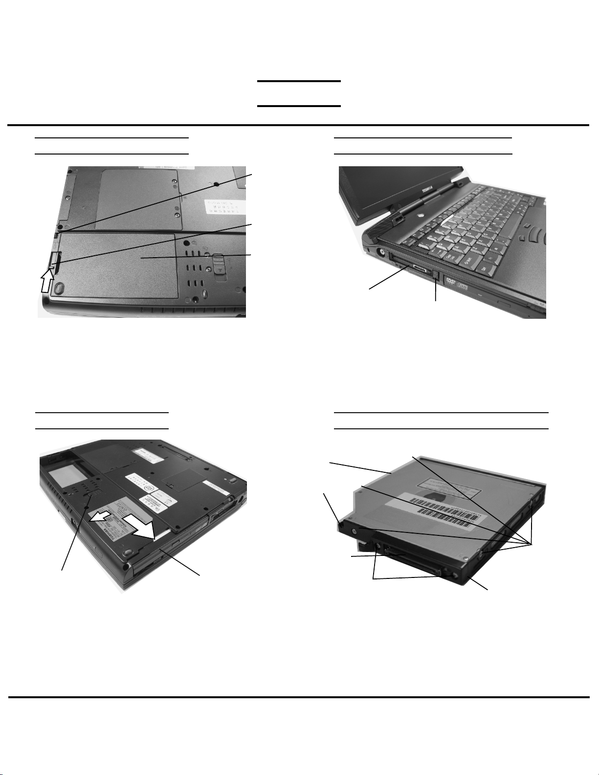
BATTERY PACK REMOVAL
1. Turn the computer upside down as shown.
2. Slide the battery lock to unlock position.
3. Slide battery release lever in the direction of the
arrow.
3. Lift out the battery.
SELECT BAY REMOVAL
OPTIONAL PC CARD REMOVAL
Battery
Lock
Release
lever
Battery
Pack
PC card
Eject button
1. Press the eject button of the PCCard you want to
remove.
2. Press the extended eject button to pop the PC card
out.
3. Grasp the PC card and remove it.
Note: Before removing any PC Card device, make
sure it is “STOPPED” in the PC Card manager.
CD-R/DVD-ROM DRIVE DISASSEMBLY
Release lever
1. Turn the computer upside down.
2. Slide the release lever in the direction of the arrow.
3. Pull out the select bay device in the direction of the
arrow.
Select bay
device
TOSHIBA
CD-R/DVD-ROM
drive
Base cover
Connector
1. Remove five M2x3 silver flat head screws securing
the base cover and lift out the cover.
2. Remove two M2x8 silver screws securing the
connector cover.
3. Remove the connector cover and the connector
from the CD-R/DVD-ROM drive.
M2x8 silver
screws
M2x3 silver
flat head
screws
Connector cover
Tough Enough for Today’s World.
Download service manual and resetter printer at http://printer1.blogspot.com
FIELD REPLACEABLE UNIT DOCUMENTATION
TM
Satellite
TE2000
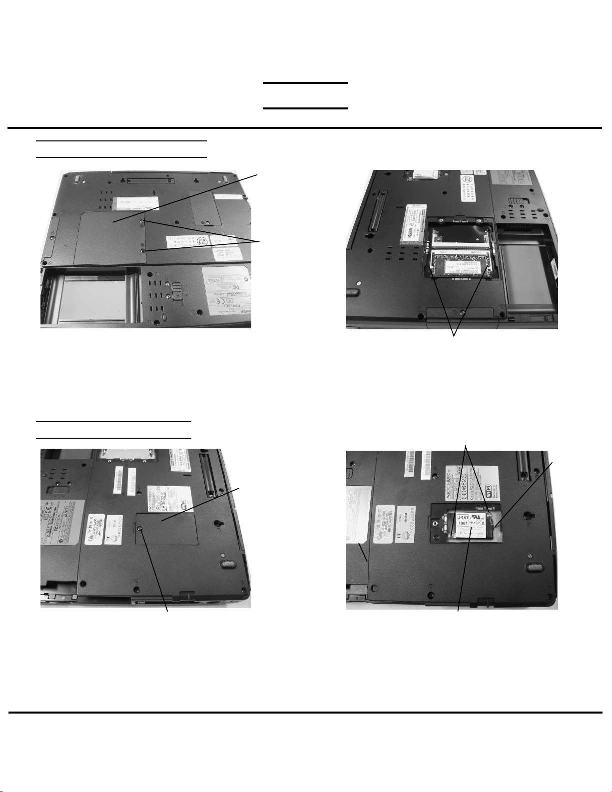
MEMORY MODULE REMOVAL
Memory
slot cover
M2.5x4
black
screws
1. Turn the computer upside down.
2. Remove two M2.5x4 black screws securing the
memory cover.
3. Lift out the memory slot cover.
MODEM BOARD REMOVAL
Modem slot
cover
M2.5x4 black screw
1. Remove one M2.5x4 black screw securing the modem
slot cover.
2. Insert your finger nail or the case separator into the
notched side of the cover and lift up to release the two
latches securing the left side of the modem slot cover.
Memory clips
4. Spread the memory clips outward and pull the
memory module out of the connector on a
45 degree angle.
M2x4 silver screws
Modem
harness
Modem board
3. Disconnect the modem harness from the modem
board.
4. Remove two M2x4 silver screws securing the
modem board.
5. Lift up the modem board to disconnect it from the
system board.
TOSHIBA
Tough Enough for Today’s World.
Download service manual and resetter printer at http://printer1.blogspot.com
 Loading...