

Toshiba Satellite C650, Satellite C655, Satellite Pro C650, Satellite Pro C655 Maintenance Manual

Toshiba Personal Computer
Satellite C650/C655
(PSC08x/PSC09x)
Maintenance Manual
TOSHIBA CORPORATION
S/ No
Satellite/Satellite Pro/C650/C655 Maintenance Manual

Copyright
© 2010 by Toshiba Corporation. All rights reserved. Under the copyright laws, this manual
cannot be reproduced in any form without the prior written permission of Toshiba. No patent
liability is assumed with respect to the use of the information contained herein.
Toshiba Satellite/Satellite Pro/C650/C655 Maintenance Manual
First edition April of 2010
Disclaimer
The information presented in this manual has been reviewed and validated for accuracy. The
included set of instructions and descriptions are accurate for the Satellite/Satellite
Pro/C650/C655 at the time of this manual's production. However, succeeding computers and
manuals are subject to change without notice. Therefore, Toshiba assumes no liability for
damages incurred directly or indirectly from errors, omissions, or discrepancies between any
succeeding product and this manual.
Trademarks
Intel and Pentium are registered trademarks of Intel Corporation.
IBM, IBM PC/XT, PC/AT, PS/2 and OS/2 are registered trademarks of IBM Corporation.
Windows 7 home edition are registered trademarks of Microsoft Corporation.
Sound Blaster and Pro are trademarks of Creative Technology Ltd.
UNIX is a registered trademark of X/Open Company Ltd.
NetWare are registered trademarks of Novell, Inc.
All other properties are trademarks or registered trademarks of their respective holders.
ii Satellite/Satellite Pro/C650/C655 Maintenance Manual
Preface
This maintenance manual describes how to perform hardware service maintenance for the
Toshiba Personal Computer Satellite/Satellite Pro/C650/C655 , referred to as
Satellite/Satellite Pro/C650/C655 in this manual.
The procedures described in this manual are intended to help service technicians isolate
faulty Field Replaceable Units (FRUs) and replace them in the field.
SAFETY PRECAUTIONS
Four types of messages are used in this manual to bring important information to your
attention. Each of these messages will be italicized and identified as shown below.
DANGER: “Danger” indicates the existence of a hazard that could result in death or
serious bodily injury, if the safety instruction is not observed.
WARNING: “Warning” indicates the existence of a hazard that could result in bodily
injury, if the safety instruction is not observed.
CAUTION: “Caution” indicates the existence of a hazard that could result in property
damage, if the safety instruction is not observed.
NOTE: “Note” contains general information that relates to your safe maintenance
service.
Improper repair of the computer may result in safety hazards. Toshiba requires service
technicians and authorized dealers or service providers to ensure the following safety
precautions are adhered to strictly.
Be sure to fasten screws securely with the right screwdriver. If a screw is not fully
fastened, it could come loose, creating a danger of a short circuit, which could cause
overheating, smoke or fire.
If you replace the battery pack, RTC battery or backup battery, be sure to use only the
same model battery or an equivalent battery recommended by Toshiba. Installation of
the wrong battery can cause the battery to explode.
Satellite/Satellite Pro/C650/C655 Maintenance Manual iii

The manual is divided into the following parts:
Chapter 1 Hardware Overview describes the Satellite/Satellite Pro/C650/C655
system unit and each FRU.
Chapter 2 Troubleshooting Procedures explains how to diagnose and resolve
FRU problems.
Chapter 3 Test and Diagnostics describes how to perform test and diagnostic
operations for maintenance service.
Chapter 4 Replacement Procedures describes the removal and replacement of the
FRUs.
Appendices The appendices describe the following:
Handling the LCD module
Board layout
Keyboard scan/character codes
Key layout
iv Satellite/Satellite Pro/C650/C655 Maintenance Manual

Conventions
This manual uses the following formats to describe, identify, and highlight terms and
operating procedures.
Acronyms
On the first appearance and whenever necessary for clarification acronyms are enclosed in
parentheses following their definition. For example:
Read Only Memory (ROM)
Keys
Keys are used in the text to describe many operations. The key top symbol as it appears on
the keyboard is printed in boldface type.
Key operation
Some operations require you to simultaneously use two or more keys. We identify such
operations by the key top symbols separated by a plus (+) sign. For example, Ctrl + Pause
(Break) means you must hold down Ctrl and at the same time press Pause (Break). If
three keys are used, hold down the first two and at the same time press the third.
User input
Text that you are instructed to type in is shown in the boldface type below:
DISKCOPY A: B:
The display
Text generated by the XXXXX that appears on its display is presented in the type face
below:
Format complete
System transferred
Satellite/Satellite Pro/C650/C655 Maintenance Manual v

Table of Contents
Chapter 1 Hardware Overview
1.1 Features ................................................................................................................................3
1.2 System Unit Components ..................................................................................................10
1.3 2.5-inch HDD .....................................................................................................................15
1.4 DVD Super Multi (+-R Double Layer) ..............................................................................16
1.5 Power Supply .....................................................................................................................17
1.6 Batteries .............................................................................................................................18
1.6.1 Main Battery ...........................................................................................18
1.6.2 Battery Charging Control .......................................................................18
1.6.3 One time RTC Battery ............................................................................19
Chapter 2 Troubleshooting
2.1 Outline .................................................................................................................... 2-1
2.2 Basic Flowchart ...................................................................................................... 2-2
2.3 Power Supply ......................................................................................................... 2-6
Procedure 1 Power Icon Check ........................................................................... 2-6
Procedure 2 Connection Check ........................................................................... 2-7
Procedure 3 Replacement Check ........................................................................ 2-7
2.4 System Board ......................................................................................................... 2-8
Procedure 1 Message Check ............................................................................... 2-8
Procedure 2 Test Program Check ....................................................................... 2-9
Procedure 3 Replacement Check ........................................................................ 2-9
2.5 HDD ..................................................................................................................... 2-10
Procedure 1 Message Check ............................................................................. 2-10
Procedure 2 Partition Check ............................................................................. 2-10
Procedure 3 Format Check................................................................................ 2-11
Procedure 4 Test Program Check ..................................................................... 2-11
Procedure 5 Connector Check and Replacement Check .................................. 2-13
vi Satellite/Satellite Pro/C650/C655 Maintenance Manual

2.6 Keyboard .............................................................................................................. 2-14
Procedure 1 Test Program Check ..................................................................... 2-14
Procedure 2 Connector Check and Replacement Check ................................... 2-14
2.7 Display ................................................................................................................. 2-15
Procedure 1 External Monitor Check ............................................................... 2-15
Procedure 2 Test Program Check ..................................................................... 2-15
Procedure 3 Connector Check and Replacement Check ................................... 2-15
2.8 ODD (Optical Disk Drive) ................................................................................... 2-17
Procedure 1 ODD Cleaning Check ................................................................... 2-17
Procedure 2 Test Program Check ..................................................................... 2-17
Procedure 3 Connector Check and Replacement Check ................................... 2-17
2.9 LAN ...................................................................................................................... 2-19
Procedure 1 Test Program Check ..................................................................... 2-19
Procedure 2 Connector Check and Replacement Check ................................... 2-19
2.10 Audio Test ............................................................................................................ 2-20
Procedure 1 Test Program Check ..................................................................... 2-20
Procedure 2 Connector Check and Replacement Check ................................... 2-20
2.11 Cooling Module .................................................................................................... 2-21
Procedure 1 Test Program Check ..................................................................... 2-21
Procedure 2 Connector Check and Replacement Check ................................... 2-21
Chapter 3 Diagnostic Programs
3.1 General ...................................................................................................................... 1
3.2 Quick Start ................................................................................................................. 3
3.2.1 Quick Test ............................................................................................... 3
3.2.2 Customization Test .................................................................................. 3
3.2.3 Keyboard Layout test .............................................................................. 7
3.2.4 Audio Play Test ....................................................................................... 8
3.2.5 Audio Record Test .................................................................................. 8
3.2.6 DMI Read ................................................................................................ 9
3.2.7 DMI Write ............................................................................................... 9
Satellite/Satellite Pro/C650/C655 Maintenance Manual vii

3.2.8 System Information ................................................................................10
3.2.9 Demonstrate LCD Panel Type ...............................................................12
3.2.10 View Logs ..............................................................................................12
3.2.11 Exit to Free DOS ...................................................................................12
3.2.12 The Diagnostics Screen Explanation......................................................12
3.3 Options .....................................................................................................................16
3.3.1 Overview ................................................................................................16
3.3.2 Batch Parameters Configuration ............................................................17
3.3.3 Item’s Parameters Configuration ...........................................................19
3.3.4 Load Batch Parameters ...........................................................................20
3.3.5 Save Batch Parameters ...........................................................................21
3.3.6 LOG Parameters Setting .........................................................................21
3.3.7 Specify LOG Viewer ..............................................................................22
3.3.8 Display LOG File ...................................................................................23
3.3.9 LOG Viewer ...........................................................................................23
3.3.10 LOG File Sample ...................................................................................25
3.4 Subtests .....................................................................................................................26
3.5 System Test ..............................................................................................................29
3.6 Memory Test ............................................................................................................34
3.7 Storage ......................................................................................................................40
3.8 Video ........................................................................................................................44
3.9 Communication (COMM) ........................................................................................52
3.10 Peripheral .................................................................................................................53
3.11 Error Codes and description .....................................................................................56
3.12 Quick Test Item List ................................................................................................... i
Chapter 4 Replacement Procedures
4.1 General ................................................................................................................... 4-1
Safety Precautions ................................................................................................ 4-2
Safety Precautions ................................................................................................ 4-2
Before You Begin ................................................................................................ 4-4
Disassembly Procedures ...................................................................................... 4-5
viii Satellite/Satellite Pro/C650/C655 Maintenance Manual

Assembly Procedures ........................................................................................... 4-5
Tools and Equipment ........................................................................................... 4-6
Screw Tightening Torque .................................................................................... 4-6
Colors of Screw Shanks ....................................................................................... 4-7
Symbols of Screws on the Computer Body ......................................................... 4-7
Symbol examples ................................................................................................. 4-7
4.2 Battery Pack/PC card/Bridge Media ...................................................................... 4-8
4.2.1 Battery Pack ......................................................................................... 4-8
Removing the Battery Pack ................................................................................. 4-8
Installing the Battery Pack ................................................................................... 4-9
4.2.2 PC Card .............................................................................................. 4-10
Removing the PC Card ...................................................................................... 4-10
Installing the PC Card ........................................................................................ 4-10
4.3 Memory Module ................................................................................................... 4-11
Removing the Memory Module ......................................................................... 4-11
Installing the Memory Module .......................................................................... 4-12
4.4 HDD ..................................................................................................................... 4-13
Removing the HDD ........................................................................................... 4-13
Installing the HDD ............................................................................................. 4-15
4.5 ODD Bay Module ................................................................................................ 4-16
Removing the ODD Bay Module ...................................................................... 4-16
Installing the ODD Bay Module ........................................................................ 4-17
Disassembling the ODD Drive .......................................................................... 4-18
Assembling the ODD Drive ............................................................................... 4-18
4.6 Keyboard and RTC battery .................................................................................. 4-19
Removing Keyboard and RTC battery .............................................................. 4-19
Installing the Keyboard and RTC battery .......................................................... 4-20
4.7 Wireless LAN Card .............................................................................................. 4-21
Removing the Wireless LAN Card .................................................................... 4-21
Installing the Wireless LAN Card...................................................................... 4-22
4.8 Top Cover ............................................................................................................. 4-23
Removing the Top Cover ................................................................................... 4-23
Satellite/Satellite Pro/C650/C655 Maintenance Manual ix

Installing the Top Cover .................................................................................... 4-24
4.9 Display Assembly ................................................................................................ 4-25
Removing the Display Assembly ....................................................................... 4-25
Installing the Display Assembly ........................................................................ 4-27
4.10 System Board ....................................................................................................... 4-28
Removing the System Board ............................................................................. 4-28
Installing the System Board ............................................................................... 4-29
4.11 CPU Cooling Module and Fan ............................................................................. 4-30
Remove the CPU cooling module and Fan ........................................................ 4-30
Installing the CPU Cooling Module and Fan ..................................................... 4-33
4.12 CPU ...................................................................................................................... 4-34
Removing the CPU ............................................................................................ 4-34
Installing the CPU .............................................................................................. 4-35
4.13 Display Mask ........................................................................................................ 4-37
Removing the Display Mask .............................................................................. 4-37
Installing the Display Mask ............................................................................... 4-37
4.14 FL Inverter Board ................................................................................................. 4-38
Removing the FL Inverter Board ....................................................................... 4-38
Installing the FL Inverter Board ........................................................................ 4-39
4.15 LCD Module (CCFL panel) ................................................................................. 4-40
Removing the LCD module ............................................................................... 4-40
Installing the LCD Module ................................................................................ 4-42
4.16 LED Module (LED panel) .................................................................................... 4-43
Removing the LED module ............................................................................... 4-43
Installing the LED Module ................................................................................ 4-45
4.17 CCD Board and MIC ............................................................................................ 4-46
Removing the CCD Board and MIC .................................................................. 4-46
Installing the CCD Board and MIC ................................................................... 4-47
4.18 Power Button Board ............................................................................................. 4-48
Removing the Power Button Board ................................................................... 4-48
Installing the Power Button Board ..................................................................... 4-49
4.19 Speakers ............................................................................................................... 4-50
x Satellite/Satellite Pro/C650/C655 Maintenance Manual

Removing the Speakers ..................................................................................... 4-50
Installing the Speakers ....................................................................................... 4-51
4.20 Touchpad Bracket ................................................................................................ 4-52
Removing the Touchpad Bracket ...................................................................... 4-52
Installing the Touchpad bracket ......................................................................... 4-53
Satellite/Satellite Pro/C650/C655 Maintenance Manual xi

Appendices
Appendix A Handling the LCD Module ........................................................................... A-1
Appendix B Board Layout .................................................................................................B-1
Appendix C Keyboard Scan/Character Codes ...................................................................C-1
Appendix D Key Layout.................................................................................................... D-1
xii Satellite/Satellite Pro/C650/C655 Maintenance Manual

Chapter 1
Hardware Overview
i Satellite/Satellite Pro/C650/C655 Maintenance Manual

1 Hardware Overview
Chapter 1 Contents
1.1 Features ............................................................................................................................... 3
1.2 System Unit Components .................................................................................................. 10
1.3 2.5-inch HDD .................................................................................................................... 15
1.4 DVD Super Multi (+-R Double Layer) ............................................................................. 16
1.5 Power Supply .................................................................................................................... 17
1.6 Batteries ............................................................................................................................. 18
1.6.1 Main Battery .......................................................................................... 18
1.6.2 Battery Charging Control....................................................................... 18
1.6.3 One time RTC Battery ........................................................................... 19
Figures
Figure 1-1 ID Parts Description Placement ............................................................................... 7
Figure 1-2 Computer Block Diagram ........................................................................................ 8
Figure 1-3 System Board Configurations .................................................................................. 9
Figure 1-4 System Unit Block Diagram .................................................................................. 10
Figure 1-5 SATA HDD ........................................................................................................... 15
Figure 1-6 DVD Super Multi Drive ........................................................................................ 16
Tables
Table 1-1 HDD Specifications ................................................................................................ 15
Table 1-2 DVD Super Multi Drive Specifications .................................................................. 16
Table 1-3 Battery Specifications ............................................................................................. 18
Table 1-4 Quick/Normal Charging Time ................................................................................ 18
ii Satellite/Satellite Pro/C650/C655 Maintenance Manual

1 Features 1 Hardware Overview
1.1 Features
Toshiba Satellite C650/C655 and Satellite Pro C650/C655 is a full size notebook PC based on
the mobile Intel Core2 Duo, Pentium or Celeron Processor, providing high-speed processing
capabilities and advanced features. The computer employs a Lithium Ion battery that allows it
to be battery-operated for a longer period of time. The display uses 15.6-inch WXGA HD LCD
panel, at a resolution of 1366x768. The Micro-FCPGA Socket supports BTO/CTO for the CPU
so that the system can be designed to suit your needs.
The computer has the following features:
Processor
CPU is mobile Intel Core2 Duo, Dual Core or Celeron Processor:
Core2 Duo Processor (800MHz FSB)
T6570(2.10G) Hz
Pentium Processor (800MHz FSB)
T4400(2.20G) Hz
Celeron Processor (800MHz FSB)
T3100(1.90G) Hz
900 (2.20G) Hz
Host Bridge System Controller
System Controller: Intel Cantiga GM45/GL40 + ICH9M.
Graphics
Intel GM45/GL40 integrated graphics.
Satellite/Satellite Pro/C650/C655 Maintenance Manual 3

1 Hardware Overview 1 Features
Memory
The computer has two SO-DIMM slots, which come standard with DDR2-800MHz
(PC2-6400) or DDR3-1066MHz (PC3-8500) memory module. DDR2 is driven at 1.8V;
DDR3 is driven at 1.5V. It accepts BTO/CTO for your memory requirements. It can
incorporate up to 8.0GB for GM45 and 4.0GB for GL40 of main memory.
Using the following sizes of memory modules:
y 1024 MB (128M×64) / DDR2-800MHz or DDR3-1066MHz
y 2048 MB (256M×64) / DDR2-800MHz or DDR3-1066MHz
y 4096 MB (512M×64) / DDR3-1066MHz
Hard Disk Drive (HDD)
The computer accommodates 2.5-inch 9.5mm height Serial ATA HDD with following
storage capacities:
y 250 GB (9.5mm thick) SATA (5,400rpm)
y 320 GB (9.5mm thick) SATA (5,400rpm)
y 500 GB (9.5mm thick) SATA (5,400rpm)
ODD
The computer accommodates a fixed 12.7mm ODD with one of following types:
y Tray Type DVD Super Multi +-R Double Layer drive
y Tray Type DVD Super Multi +-R Double Layer with Label Flash™ drive
Display
LCD displays come in the following types at resolution 1366x768:
y 15.6” WXGA HD 1366x768 CSV CCFL display
y 15.6” WXGA HD 1366x768 CSV LED display
On-Board LAN
The internal LAN supports 10/100Mbit Ethernet, enabling connection to a LAN at up to
100Mbps. It supports Wake-up on LAN from S3/S4/S5 and PXE boot support. This
internal LAN has RJ45 jack to directly accommodate a LAN cable.
4 Satellite/Satellite Pro/C650/C655 Maintenance Manual

1 Features 1 Hardware Overview
Wireless LAN
The internal Mini Card slot supports IEEE802.11bg (Russia only) / IEEE802.11bgn
(WW) cards. The Antenna has two wires dual band.
Sound System
CONEX CX20671 integrated audio controller supports multimedia. The sound system
contains the following:
y Stereo speakers
y Internal microphone
y External microphone jack
y External headphone jack
Keyboard
34 kinds’ countries keyboard, which is Toshiba A4 with numeric keypad flat one.
Toshiba Touch Pad
Normal Gesture Touch Pad (w/ 2 mechanical buttons)
USB Port
The computer has two USB 2.0 ports. It is supported to daisy-chain a maximum of 127
USB devices. The serial data transfer rate is 480Mbps, 12Mbps and 1.5Mbps. These
ports support PnP installation and hot plugging.
RGB External Monitor Port
A 15-pin external monitor port is provided, through which the computer automatically
recognizes an external VESA DDC 2B compatible monitor.
Bridge Media Slot
This slot is for your memory card requirements like SD/SDHC/SDXC and MMC Cards
to provide memory card read on your computer.
Satellite/Satellite Pro/C650/C655 Maintenance Manual 5

1 Hardware Overview 1 Features
Battery
The computer has a removable 3/6 Cell Lithium Ion battery pack and a onetime RTC
battery (non-rechargeable)
6 Satellite/Satellite Pro/C650/C655 Maintenance Manual
1 Features 1 Hardware Overview
Figures 1-1/1-2/1-3 and 1-4 show the computer and its system unit configuration,
respectively.
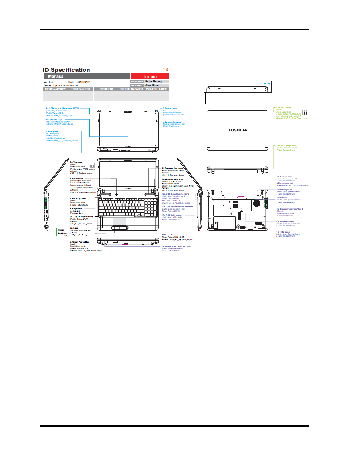
Figure 1-1 ID Parts Description Placement
Satellite/Satellite Pro/C650/C655 Maintenance Manual 7
1 Hardware Overview 1 Features
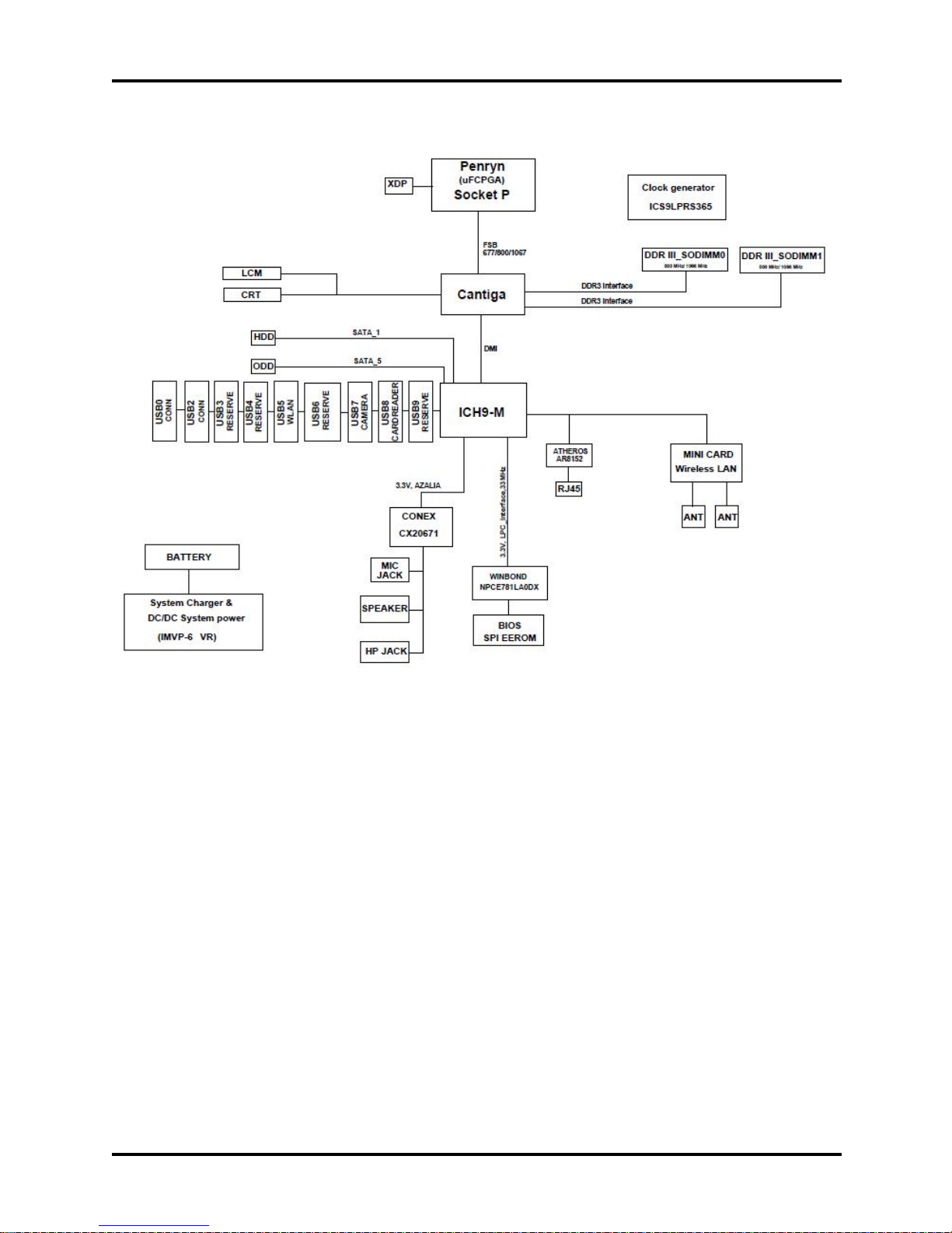
Figure 1-2 Computer Block Diagram
8 Satellite/Satellite Pro/C650/C655 Maintenance Manual
1 Features 1 Hardware Overview
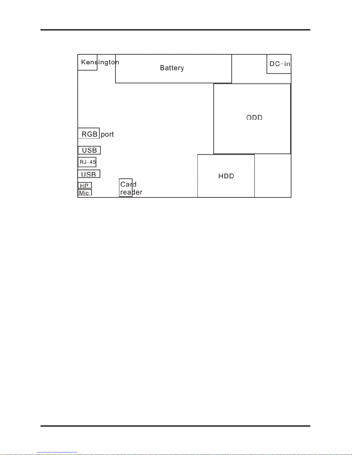
Figure 1-3 System Board Configurations
Satellite/Satellite Pro/C650/C655 Maintenance Manual 9
1 Hardware Overview 1B1.2 System Unit Components
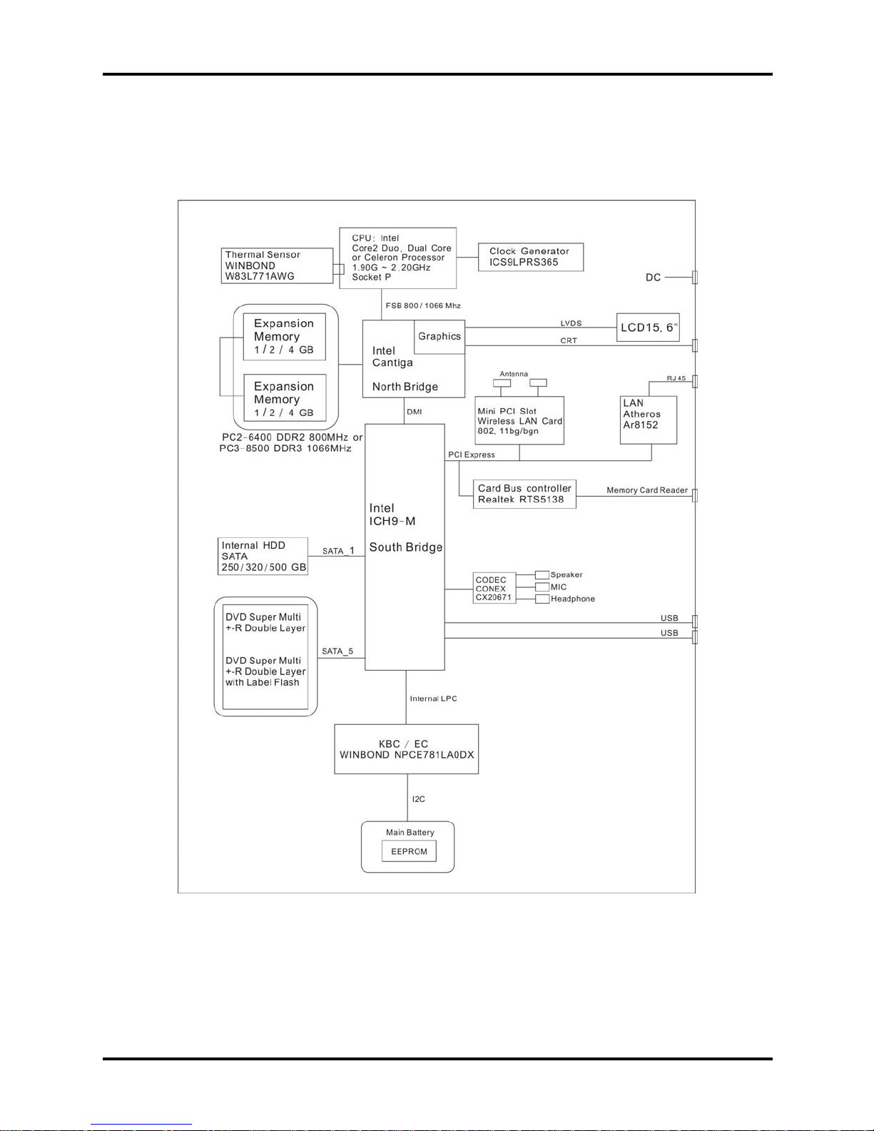
1.2 System Unit Components
Figure 1-4 is Block Diagram of the System Unit.
10 Satellite/Satellite Pro/C650/C655 Maintenance Manual
Figure 1-4 System Unit Block Diagram

1.2 System Unit Components 1 Hardware Overview
The system unit of the computer consists of the following components:
Processor: Intel Core2 Duo, Pentium and Celeron Processor.
y Core2 Due Processor (FSB, 800MHz)
− Core Speed: 2.10 GHz
− System Bus: 800 MHz
− On-Die Level 2 Cache: 2 MB (T6570)
y Pentium Processor (FSB, 800MHz)
− Core Speed: 2.20 GHz
− System Bus: 800 MHz
− On-Die Level 2 Cache: 2 MB (T4400)
y Celeron Processor (FSB, 800MHz)
− Core Speed: 1.90/2.20 GHz
− System Bus: 800 MHz
− On-Die Level 2 Cache: 1 MB (T3100/900)
Memory: Two expansion memory slots are provided. They can hold 1.0/2.0/4.0 GB memory
modules available as options to grow up to 4.0GB for GL40 and 8.0GB for GM45.
y PC2-6400 (800MHz) DDR2 or PC3-8500 (1066MHz) DDR3 SDRAM supported
y 1024/2048/4096MB modules supported
− 1024 MB (128M x 64)
− 2048 MB (256M x 64)
− 4096 MB (512M x 64)
y DDR2 1.8 volt operation or DDR3 1.5 volt operation
y No parity bit
y 64-bit data transfer
BIOS ROM (Flash EEPROM)
y 8Mb x 1 chip (1024KB flash parts)
− NvStorage Size : 64K
− NvStorage Free Space : 63K
− FV00 Size : 716K
− FV00 Free Space : 45K
− FV01 Size : 128K
− FV01 Free Space : 0K
Satellite/Satellite Pro/C650/C655 Maintenance Manual 11

1 Hardware Overview 1B1.2 System Unit Components
System Controller
y North Bridge: Intel GM45/GL40
− CPU Interface and Control
− System Memory Support
− PCI Express* Graphics (PEG) Interface
− Integrated Display Interface Support
− Internal Graphics Features
− Direct Media Interface (DMI)
− Power Management
− Security and Manageability
− Serial ATA Interface
− ICH9 Audio Control
y South Bridge: Intel ICH9-M
− Direct Media Interface (DMI)
− PCI Express* Interface
− Serial ATA (SATA) Controller
− Advanced Host Controller Interface (AHCI)
− Intel Matrix Storage Technology
− PCI Bus Interface
− Interrupt Controller
− Low Pin Count (LPC) Interface
− Serial Peripheral Interface (SPI)
− Compatibility Modules
− Advanced Programmable Interrupt Controller (APIC)
− Universal Serial Bus (USB) Controller
− LAN Controller
− RTC
− GPIO
− Enhanced Power Management
− Intel I/O Virtualization (VT-d) Support
− System Management Bus (SMBus 2.0)
− Intel High Definition Audio Controller
− Enhanced DMA Controller
Card Bus Controller
y Realtek RTS5138
− Memory Card Reader Controller
Audio Controller
12 Satellite/Satellite Pro/C650/C655 Maintenance Manual

1.2 System Unit Components 1 Hardware Overview
CONEX CX20671 integrated audio controller supports multimedia. The sound system
features contain the following:
y 24-bit, two pairs of independent DACs and three pairs of independent ADCs
y Integrated 2 WRMS (per channel) class-D stereo speaker amplifier with Spread
Spectrum and 10-kV ESD withstand capability
y Digital Microphone interface with internal MIC boost supporting up to two multiplexed
digital element array microphones
y Internal microphone boost
− Digital: 0, 12, 24, 36, 48 dB
− Analog: 0, 10, 20, 30, 40 dB
y Independent sampling rate for DAC and ADC; supports audio formats ranging from 16-
bit, 44.1 kHz to 24-bit, 192 kHz
y Pop Shield: pops and clicks reduction circuitry, including class-D speaker outputs
y Jack sense detects up to four jacks using only one sense pin
y Digital Mixer
y Supports 32-bit/64-bit Windows OS and Linux
KBC/EC (Keyboard Controller/Embedded Controller)
A KBC Winbond NPCE781LA0DX chip is used to serve as KBC/EC and Super IO:
y KBC
− Scan controller function
− Interface controller function
y EC
− Power supply sequence control
− Overheat shutdown support
− LED control
− Beep control
− Device ON/OFF
− Cooling fan speed control
− Universal I/O port
− Battery capacity check
− Flash memory reprogramming function
− EC access interface
− I2C communication control
Battery EEPROM
Satellite/Satellite Pro/C650/C655 Maintenance Manual 13

1 Hardware Overview 1B1.2 System Unit Components
y 24C02 equivalent (128 words x 16 bits, I2C interface) integrated in battery pack
− Storing records of battery use
Clock Generator
y ICS ICS9LPRS365
− Generating the clock signal required for the system
LAN Controller
y ATHEROS_AR8152 - 10/100Mbit
− IEEE 802.3 10BASE-T/100BASE-TX compliant physical layer
interface
− IEEE 802.3u Auto-Negotiation support
− Digital Adaptive Equalization control
− 10BASE-T auto-polarity correction
− LAN Connect interface
− Automatic detection of “unplugged mode”
− Remote boot (PXE 2.1)
− Smart power down when link is not detected
Wireless LAN Controller
y Support following 2 kinds of mini PCI wireless LAN cards
− IEEE 802.11bg
− IEEE 802.11bgn
y Data Rate
− IEEE 802.11bg: Standard 54M bps
− IEEE 802.11bgn: Standard 54M bps
y Frequency Channel
− IEEE802.11bg: 2.4GHz
− IEEE802.11bgn: 2.4GHz
14 Satellite/Satellite Pro/C650/C655 Maintenance Manual
2B1.3 2.5-inch HDD 1 Hardware Overview
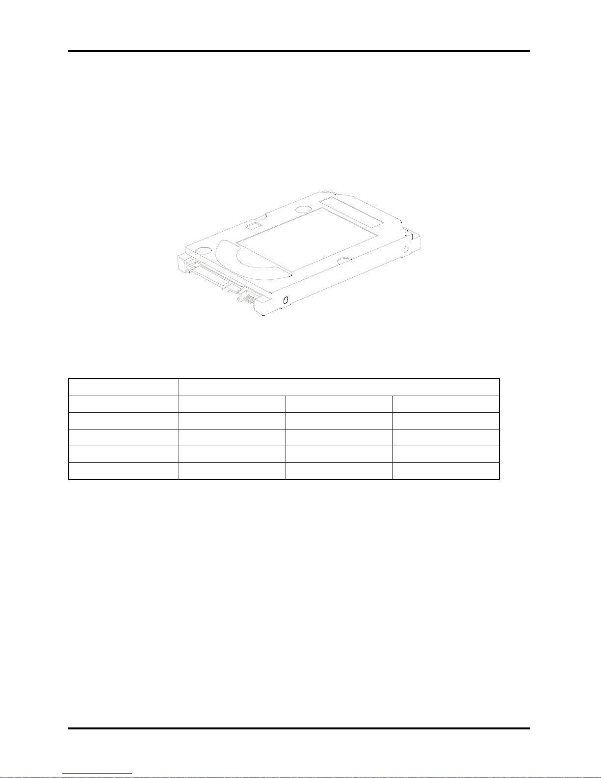
1.3 2.5-inch HDD
The computer contains an extremely low-profile, lightweight and high-performance HDD. The
HDD incorporates 9.5 mm height magnetic disk and mini-Winchester type magnetic heads. The
HDD interface conforms to Serial ATA. Storage capacities supported are 250, 320 & 500 GB.
The HDD is shown in Figure 1-5 and some of its specifications are listed in Table 1-1.
Figure 1-5 SATA HDD
Item Specifications
Capacity (GB) 250 GB 320 GB 500 GB
Rotational Speed (RPM) 5400 rpm 5400 rpm 5400 rpm
Height 9.5 mm 9.5 mm 9.5 mm
User Data Sectors 488,397,168 625,142,448 976,773,168
Bytes / Sector 512 512 512
Table 1-1 HDD Specifications
Satellite/Satellite Pro/C650/C655 Maintenance Manual 15
1.4 DVD Super Multi (+-R Double Layer) 1 Hardware Overview
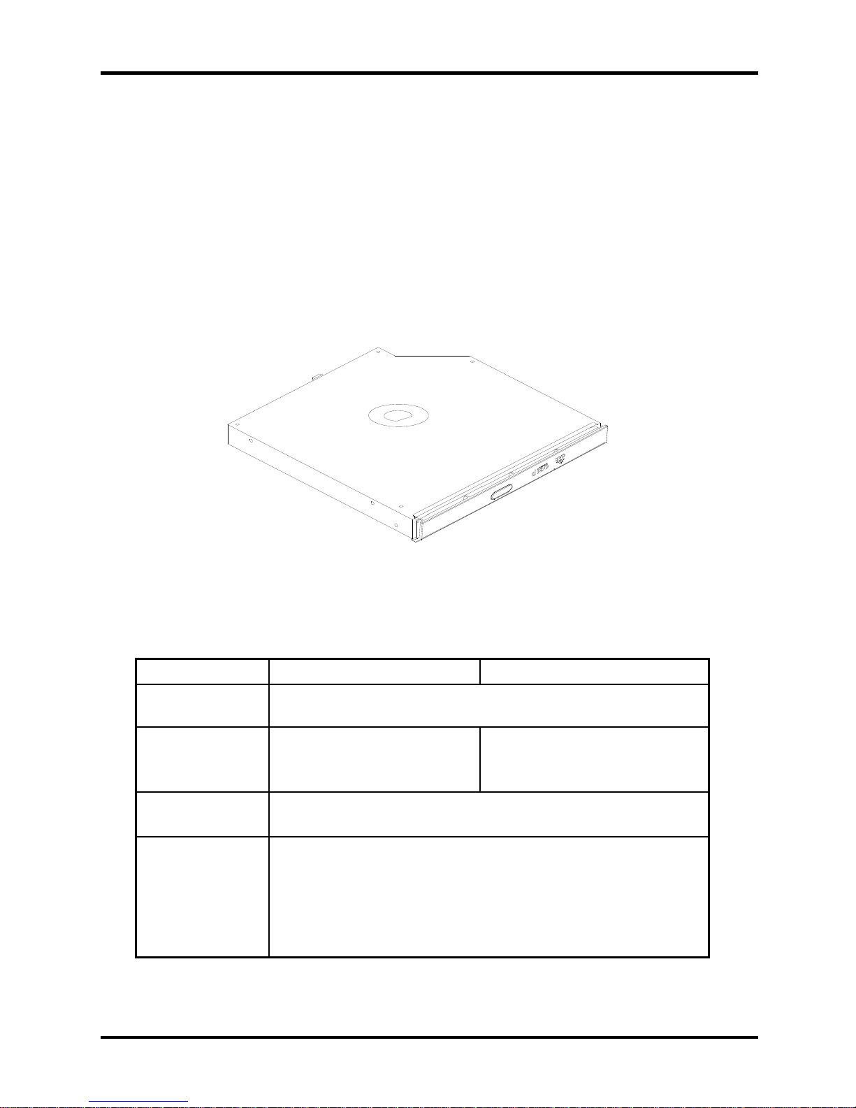
1.4 DVD Super Multi (+-R Double Layer)
The DVD Super Multi drive accepts 12-cm (4.72-inch) and 8-cm (3.15-inch) discs. At
maximum, the drive can play back a DVD at 8x speed, read CD-ROM at 24x speed, and write
CD-R at 24x speed, CD-RW at 4x speed, US CD-RW at 24x speed, High Speed CD-RW at 10x
speed, DVD-R at 8x speed, DVD-RW at 6x speed, DVD+R at 8x speed, DVD+R (Double Layer)
at 6x speed, DVD-R (Double Layer) at 6x speed, DVD+RW at 8x speed and DVD-RAM at 5x
speed.
DVD Super Multi Drive is shown in Figure 1-7 and its specifications are listed in Table 1-2.
Item DVD-ROM mode CD-ROM mode
Data Transfer Rate
(Mbytes/s)
Access Time (ms)
Average Random
Access
Data Buffer Size
(Mbytes)
Formats Supported
Figure 1-6 DVD Super Multi Drive
Table 1-2 DVD Super Multi Drive Specifications
33.3 (U-DMA transfer mode 2)
16.7 (PIO mode 4, Multiword DMA mode 2)
130 ms 130 ms
2MB
DVD:
DVD-VIDEO, DVD-ROM, DVD-R, DVD-RW, DVD-RAM,
DVD+R, DVD+-R (Double Layer), DVD+RW.
CD:
CD-DA, CD-ROM, CD-R, CD-RW, CD-ROMXA, Photo CD (Multi-
Session), Video CD, CD-Extra (CD+), CD-Text.
16 Satellite/Satellite Pro/C650/C655 Maintenance Manual

Fehler! Verweisquelle konnte nicht gefunden werden.(+-R Double Layer)1 Hardware Overview
1.5 Power Supply
The power supply unit provides many different voltages for the system board and performs the
following functions:
1. Power input monitor
y Checks whether the DC power supply (AC adapter) is connected to the computer.
y Checks whether the battery pack is connected to the computer.
y Monitors the DC power supply input voltage (AC Adapter output voltage).
2. Power supply's internal control
y Turns on and off the battery pack charging power supply.
y Issues a charging current instruction to the PWM control IC of the battery pack charging
power supply.
y Controls the supply of DC power supply input (AC Adapter output) to the power supply
unit.
y Controls the supply of power to the system block (load/logic circuit side).
y Controls forced shutdown if the power supply malfunctions.
3. Logic circuit control
y Instructs the gate array to enable/disable tuning the power on.
y Controls power-on/off operation.
4. Status display
y Turns on the Power LED (in green).
y Battery indicator (in amber).
5. External interface
y Performs communication through the I2C bus (via the internal EC/KBC).
y Transfers the power supply operation mode.
6. Output monitor
y Monitors the voltage output to the system block (load/logic circuit side).
y Monitors the voltage, over voltage, input/output current of the battery pack.
y Monitors the internal temperature of the battery pack.
y Monitors the supply voltage from the AC adapter.
Satellite/Satellite Pro/C650/C655 Maintenance Manual 17
1.4 DVD Super Multi (+-R Double Layer) 1 Hardware Overview
1.6 Batteries
The computer has the following 2 types of battery:
Main Battery Pack
Real Time Clock (RTC) Battery
Table 1-3 lists the specifications of these batteries.
Table 1-3 Battery Specifications
Battery Type Material Output voltage Capacity
3 Cell Lithium Ion 10.8 V 2000 mAh
Main Battery Pack
6 Cell Lithium Ion 10.8 V 4400 mAh
RTC Battery Lithium Ion 3.0 V 220 mAh
1.6.1
Main Battery
The main battery pack serves as the computer's main power source when the AC adapter
is not attached. The main battery maintains the state of the computer so that it can
resume it.
1.6.2
Battery Charging Control
Battery charging is controlled by MAXIM MAX17435ETG+. When AC adapter and
battery pack are attached to the computer, MAX17435ETG+ controls the charge on/off
state and detects a full charge.
Battery Charge
When the AC adapter is attached, the battery is charged by off-state charge when the
system is powered off or by on-state charge when it is powered on.
18 Satellite/Satellite Pro/C650/C655 Maintenance Manual
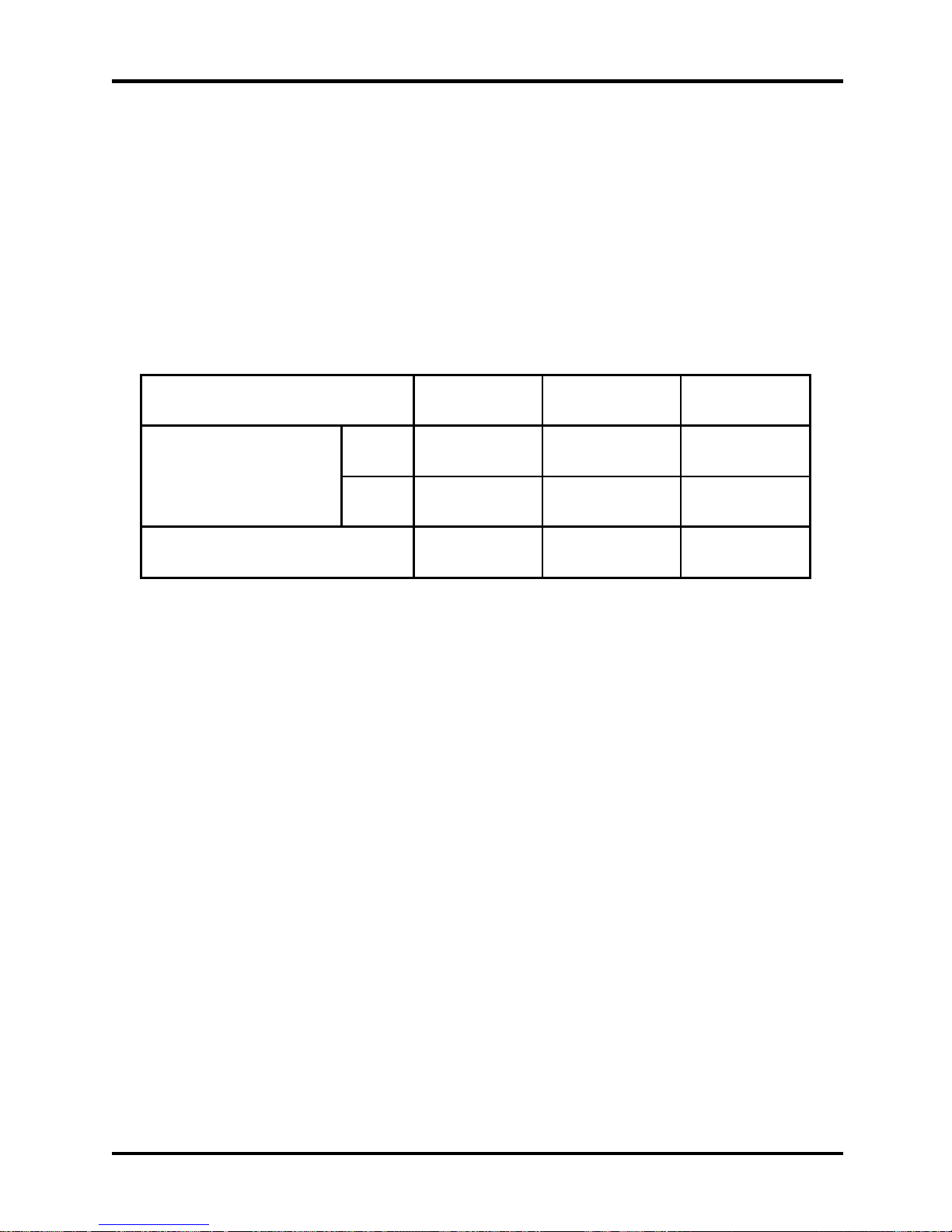
Table 1-4 Quick/Normal Charging Time
 Loading...