

Toshiba Satellite A500D Series, Satellite Pro A500D Series Maintenance Manual

Toshiba Personal Computer
Satellite
Maintenance Manual
TOSHIBA CORPORATION
[CONFIDENTIAL]

Copyright
© 2009 by Toshiba Corporation. All rights reserved. Under the copyright laws, this manual
cannot be reproduced in any form without the prior written permission of Toshiba. No patent
liability is assumed with respect to the use of the information contained herein.
Toshiba Personal Computer Satellite Maintenance Manual
First edition May. 2009
Disclaimer
The information presented in this manual has been reviewed and validated for accuracy. The
included set of instructions and descriptions are accurate for the Satellite Series at the time of this
manual's production. However, succeeding computers and manuals are subject to change without
notice. Therefore, Toshiba assumes no liability for damages incurred directly or indirectly from
errors, omissions, or discrepancies between any succeeding product and this manual.
Trademarks
IBM is a registered trademark, and OS/2 and PS/2 are trademarks of IBM Corporation.
Microsoft, MS-DOS, Windows, DirectSound and DirectMusic are registered trademarks of
Microsoft Corporation.
Intel and Pentium are registered trademarks, and SpeedStep is a trademark of Intel Corporation.
Sound Blaster is a registered trademark of Creative Technology Ltd.
Centronics is a registered trademark of Centronics Data Computer Corporation.
Photo CD is a trademark of Eastman Kodak.
All other properties are trademarks or registered trademarks of their respective holders.
ii
[CONFIDENTIAL]
Satellite A500D/Pro A500D Series Maintenance Manual
Preface
This maintenance manual describes how to perform hardware service maintenance for the Toshiba
Personal Computer Satellite, referred to as the Satellite Series in this manual.
The procedures described in this manual are intended to help service technicians isolate faulty
Field Replaceable Units (FRUs) and replace them in the field.
SAFETY PRECAUTIONS
Four types of m
essages are used in this manual to bring important information to your attention.
Each of these messages will be italicized and identified as shown below.
DANGER: “Danger” indicates the existence of a hazard that could result in death or
serious bodily injury if the safety instruction is not observed.
WARNING: “Warning” indicates the existence of a hazard that could result in bodily
injury if the safety instruction is not observed.
CAUTION: “Caution” indicates the existence of a hazard that could result in property
damage if the safety instruction is not observed.
NOTE: “Note” contains general information that relates to your safe maintenance
service.
Improper repair of the computer may result in safety hazards. Toshiba requires service technicians
and authorized dealers or service providers to ensure the following safety precautions are adhered
to strictly.
Be sure to fasten screws securely with the right screwdriver. If a screw is not fully fastened, it
could come loose, creating a danger of a short circuit, which could cause overheating,
smoke or fire.
If you replace the battery pack or RTC battery, be sure to use only the same model battery or
an equivalent battery recommended by Toshiba. Installation of the wrong battery can
cause the battery to explode.
Satellite A500D/Pro A500D Series Maintenance Manual
[CONFIDENTIAL]
iii

The manual is divided into the following parts:
Chapter 1 Hardware Overview describes the Satellite Series system unit and each
FRU.
Chapter 2 Troubleshooting Procedures explains how to diagnose and resolve FRU
problems.
Chapter 3 Test and Diagnostics describes how to perform test and diagnostic
operations for maintenance service.
Chapter 4 Replacement Procedures describes the removal and replacement of the
FRUs.
Appendices The appendices describe the following:
Handling the LCD module
Board layout
Pin assignments
Keyboard scan/character codes
Key layout
Screw torque list
Reliability
Conventions
This manual uses the following formats to describe, identify, and highlight terms and operating
procedures.
Acronyms
On the first appearance and whenever necessary for clarification, acronym
s are enclosed in
parentheses following their definition. For example:
Read Only Memory (ROM)
Keys
Keys are used in the text to describe m
any operations. The key top symbol as it appears on the
keyboard is printed in boldface type.
Key operation
iv
[CONFIDENTIAL]
Satellite A500D/Pro A500D Series Maintenance Manual

Some operations require you to simultaneously use two or more keys. We identify such operations
by the key top symbols separated by a plus (+) sign. For example, Ctrl + Pause (Break) means
you must hold down Ctrl and at the same time press Pause (Break). If three keys are used, hold
down the first two and at the same time press the third.
User input
Text that you are instructed to type in is shown in the boldface type below:
DISKCOPY A: B:
The display
Text generated by the computer that appears on its display is presented in the typeface below:
Format complete
System transferred
Satellite A500D/Pro A500D Series Maintenance Manual
[CONFIDENTIAL]
v

Table of Contents
Chapter 1 Hardware Overview
1.1 Features.............................................................................................................................1-1
1.2 2.5-inch HDD .................................................................................................................1-11
1.3 DVD Super Multi (+-R Double Layer) ..........................................................................1-13
1.4 Power Supply..................................................................................................................1-14
1.5 Batteries..........................................................................................................................1-16
1.5.1 Main Battery.....................................................................................................1-16
1.5.2 Battery Charging Control .................................................................................1-16
1.5.3 RTC Battery......................................................................................................1-17
Chapter 2 Troubleshooting Procedures
2.1 Troubleshooting Introduction..............................................................................................3
2.2 Troubleshooting Flowchart..................................................................................................4
2.3 Power Supply Troubleshooting...........................................................................................9
2.4 Display Troubleshooting ...................................................................................................14
2.5 Keyboard Troubleshooting................................................................................................17
2.6 External USB Devices Troubleshooting............................................................................19
2.7 TV-tuner Troubleshooting.................................................................................................21
2.8 TouchPad Troubleshooting................................................................................................25
2.9 Speaker Troubleshooting...................................................................................................27
2.10 Optical drive troubleshooting............................................................................................29
2.11 MoTroubleshooting...........................................................................................................32
2.12 Express card Troubleshooting...........................................................................................34
2.13 Wireless LAN Troubleshooting.........................................................................................36
2.12 Camera Troubleshooting ...................................................................................................39
2.15 Bluetooth Troubleshooting................................................................................................41
vi
[CONFIDENTIAL]
Satellite A500D/Pro A500D Series Maintenance Manual

2.16 7 in 1 card Troubleshooting...............................................................................................44
2.17 HDD Troubleshooting .........................................................................................................46
2.18 CRT failure Troubleshooting...............................................................................................48
2.19 HDMI Troubleshooting .......................................................................................................50
2.20 Display Port Troubleshooting..............................................................................................52
2.21 SPDIF Troubleshooting.......................................................................................................54
2.22 MIC Troubleshooting ..........................................................................................................56
2.23 Finger Troubleshooting........................................................................................................58
2.24 FM tuner Troubleshooting...................................................................................................60
2.25 E-SATA Troubleshooting....................................................................................................66
2.26 Felica Troubleshooting........................................................................................................69
2.27 UWB Troubleshooting.........................................................................................................71
2.28 3G Troubleshooting............................................................................................................75
Chapter 3 Tests and Diagnostics
3.1 The Diagnostic Test...............................................................................................................3
3.2 Executing the Diagnostic Test...............................................................................................4
3.3 Display Configuration ...........................................................................................................8
3.4 Audio sound Test...................................................................................................................
9
3.5 Fan ON/OFF Test..................................................................................................................9
3.6 Main Battery Charge Test....................................................................................................
3.7 FDD Test..........................................................................................................................
3.8 Memory Check.....................................................................................................................
3.9 Keyboard Test......................................................................................................................
11
…11
14
14
3.10 Mouse (Pad) Test.................................................................................................................16
3.11 LCD Pixels Mode Test ........................................................................................................
17
3.12 Magnetic switch Test...........................................................................................................18
3.13 LAN Test .............................................................................................................................
3.14 RTC Test..............................................................................................................................
Satellite A500D/Pro A500D Series Maintenance Manual
[CONFIDENTIAL]
20
23
vii

3.15 BUTTON Test……..…………...………….…….……… .……..…………...……............24
3.16 1st HDDTest ……………………………....……………..……………....….…………...26
3.17 RDMI Test………………...………………………….….……………...…..…………….27
3.18 WDMI Test …………….…………………………….…………….…....…..…………..28
Chapter 4 Replacement Procedures
4.1 General................................................................................................................................4-1
Safety Precautions...............................................................................................................4-2
Before You Begin ...............................................................................................................4-4
Disassembly Procedures .....................................................................................................4-5
Assembly Procedures..........................................................................................................4-5
Tools and Equipment..........................................................................................................4-6
Screw Tightening Torque ...................................................................................................4-6
Colors of Screw Shanks......................................................................................................4-7
Symbols of Screws on the Laptop Body.............................................................................4-7
Symbol examples................................................................................................................4-7
4.2 Battery.................................................................................................................................4-8
Removing the Battery Pack ................................................................................................4-8
Installing the Battery Pack..................................................................................................4-9
4.3 HDD..................................................................................................................................4-10
Removing the HDD ..........................................................................................................4-10
Installing the HDD............................................................................................................4-12
4.4 Memory.............................................................................................................................4-13
Removing the Optional Memory......................................................................................4-13
Installing the Optional Memory........................................................................................4-14
4.5 UWB Module....................................................................................................................4-15
4.6 Modem Card / FM Tuner..................................................................................................4-16
4.7 ODD..................................................................................................................................4-19
Removing the ODD Bay Module......................................................................................4-19
viii
Manual
[CONFIDENTIAL]
Satellite A500D/Pro A500D Series Maintenance

Installing the ODD Bay Module...................................................................................... 4-20
Disassembling the ODD Drive ........................................................................................ 4-20
Assembling the ODD Drive............................................................................................. 4-21
4.8 Keyboard Cover and Keyboard........................................................................................ 4-22
Removing the Keyboard Cover and Keyboard................................................................ 4-22
Installing the Keyboard Cover and Keyboard.................................................................. 4-24
4.9 Logic Upper Assembly .................................................................................................... 4-25
Removing the Logic Upper Assembly............................................................................. 4-25
Installing the Logic Upper Assembly .............................................................................. 4-27
4.10 Power Board..................................................................................................................... 4-28
Removing the Power Board............................................................................................. 4-28
Installing the power switch board.................................................................................... 4-28
4.11 Speakers ........................................................................................................................... 4-29
Removing the Speakers.................................................................................................... 4-29
Installing the Speakers..................................................................................................... 4-29
4.12 Bluetooth Card ................................................................................................................. 4-30
Removing the Bluetooth card .......................................................................................... 4-30
Installing the Bluetooth card............................................................................................ 4-30
4.13 Touchpad Bracket, Touchpad Boards and Fingerprint Board/
Touchpad Switch Board................................................................................................... 4-31
Removing the Touchpad Bracket, Touchpad Boards and Fingerprint Board.................. 4-31
Touchpad Bracket, Touchpad Boards and Fingerprint Board/Touchpad Switch Board . 4-32
4.14 LED board........................................................................................................................ 4-33
Removing the LED Board................................................................................................ 4-33
Installing the LED Board................................................................................................. 4-33
4.15 Thermal Fan ..................................................................................................................... 4-34
Removing the Thermal Fan.............................................................................................. 4-34
Installing the Thermal Fan............................................................................................... 4-34
4.16 WLAN Card..................................................................................................................... 4-35
Removing the WLAN Card ............................................................................................. 4-35
Installing the WLAN card................................................................................................ 4-35
4.17 Motherboard..................................................................................................................... 4-36
Satellite A500D/Pro A500D Series Maintenance Manual
[CONFIDENTIAL]
ix

Removing the Motherboard..............................................................................................4-36
Installing the Motherboard................................................................................................4-38
4.18 VGA Board and VGA Thermal Module (Optional).........................................................4-40
Removing the VGA Board and VGA Thermal Module...................................................4-40
Installing the VGA Board and VGA Thermal Module.....................................................4-41
4.19 CPU and Thermal Module................................................................................................4-42
Removing the CPU and Thermal Module.........................................................................4-42
Installing CPU and Thermal Module................................................................................4-43
4.20 Display Assembly .............................................................................................................4-45
Removing the Display Assembly......................................................................................4-45
Installing the Display Assembly.......................................................................................4-45
4.21 LCD Bezel Assembly........................................................................................................4-46
Removing the LCD Bezel Assembly................................................................................4-46
For Low-end Model..........................................................................................................4-46
For High-end Model .........................................................................................................4-48
Installing the Display Mask..............................................................................................4-55
4.22 LCD Module and Inverter Board......................................................................................4-57
Removing the LCD Module and Inverter Board ..............................................................4-57
Installing the LCD Module and Inverter Board................................................................4-62
4.23 CMOS Board and MIC.....................................................................................................4-66
Removing the CMOS Board and MIC..............................................................................4-66
Installing the CMOS Board and MIC...............................................................................4-67
4.24 Left USB Board ................................................................................................................4-68
Removing the USB Board on the Left Side......................................................................4-68
Installing the Left USB Board ..........................................................................................4-68
4.25 Right USB Board..............................................................................................................4-69
Removing the Right USB Board on the Right Side..........................................................4-69
Installing the Right USB Board........................................................................................4-71
x
[CONFIDENTIAL]
Satellite A500D/Pro A500D Series Maintenance Manual

Figures
Figure 4.1 Removing the Battery Pack.................................................................................... 4-8
Figure 4.2 Removing the HDD door ..................................................................................... 4-10
Figure 4.3 Removing the HDD from the HDD bay............................................................... 4-11
Figure 4.4 Removing the HDD plate..................................................................................... 4-11
Figure 4.5 Removing the RAM door..................................................................................... 4-13
Figure 4.6 Removing the RAM from the connectors ............................................................ 4-14
Figure 4.7 Removing the UWB module................................................................................ 4-15
Figure 4.8 Removing the modem card................................................................................... 4-16
Figure 4.9 Removing the FM Tuner...................................................................................... 4-17
Figure 4.10 Removing the ODD Bay module ......................................................................... 4-19
Figure 4.11 Removing the bracket from the ODD drive......................................................... 4-20
Figure 4.12 Removing two screws from the battery lodging .................................................. 4-22
Figure 4.13 Removing the keyboard cover.............................................................................. 4-23
Figure 4.14 Removing screws from the keyboard................................................................... 4-23
Figure 4.15 Removing the keyboard ....................................................................................... 4-24
Figure 4.16 Removing the screws from the bottom of the laptop ........................................... 4-25
Figure 4.17 Removing eight screws from the laptop............................................................... 4-26
Figure 4.18 Detaching cables from the laptop......................................................................... 4-27
Figure 4.19 Removing the power board .................................................................................. 4-28
Figure 4.20 Removing the speakers......................................................................................... 4-29
Figure 4.21 Removing the Bluetooth card............................................................................... 4-30
Figure 4.22 Removing the screws from the touchpad bracket ................................................ 4-31
Figure 4.23 Removing the Touchpad boards and Fingerprint board....................................... 4-32
Figure 4.24 Removing the LED Board.................................................................................... 4-33
Figure 4.25 Removing the thermal fan from the logic lower assembly .................................. 4-34
Figure 4.26 Removing the WLAN Card.................................................................................. 4-35
Figure 4.27 Removing motherboard from logic lower assembly............................................ 4-36
Figure 4.28 Removing the DC_IN CONN and cable.............................................................. 4-37
Figure 4.29 Picking up the motherboard ................................................................................. 4-37
Satellite A500D/Pro A500D Series Maintenance Manual
[CONFIDENTIAL]
xi

Figure 4.30 Align the DP CONN, S/PDIF CONN, Audio CONN and RJ45 CONN...............4-38
Figure 4.31 Installing the DC-in jack.......................................................................................4-39
Figure 4.32 Removing the VGA Board....................................................................................4-40
Figure 4.33 Reapply the Shinetsu 7726 grease on the thermal module
and remove any release papers..............................................................................4-41
Figure 4.34 Removing the Thermal Module spring screws .....................................................4-42
Figure 4.35 Removing the CPU................................................................................................4-43
Figure 4.36 Reapply the Shinetsu 7726 grease on the thermal module
and remove any release papers..............................................................................4-44
Figure 4.37 Removing the display assembly............................................................................4-45
Figure 4.38 Removing the LCD Bezel Assembly from the low-end model ............................4-46
Figure 4.39 Peel off the bezel...................................................................................................4-47
Figure 4.40 Pull out the hinge wall...........................................................................................4-47
Figure 4.41 Remove the bezel ..................................................................................................4-48
Figure 4.42 Removing the LCD Bezel Assembly from the high-end model ...........................4-48
Figure 4.43 Wrap the flat blade screwdriver with tape ............................................................4-49
Figure 4.44 Press the hinge wall...............................................................................................4-49
Figure 4.45 Pry up the bezel hinge wall ...................................................................................4-50
Figure 4.46 Release the rest of the hooks.................................................................................4-50
Figure 4.47 Push the right side of the bezel upward ................................................................4-51
Figure 4.48 Push the left side of the bezel upward...................................................................4-52
Figure 4.49 Release hooks from the bottom of the bezel .........................................................4-53
Figure 4.50 Release hooks from the right and left side of the bezel ........................................4-53
Figure 4.51 Release the hooks from the upper side of the bezel..............................................4-54
Figure 4.52 Press the bezel hinge wall .....................................................................................4-55
Figure 4.53 Press the bottom hooks on the display assembly ..................................................4-55
Figure 4.54 Press the left and right side of the bezel for the low-end model/Press the
hooks on the left and right side of the bezel for the high-end model....................4-56
Figure 4.55 Press the bezel upside hooks.................................................................................4-56
Figure 4.56 Removing the Inverter Board................................................................................4-57
Figure 4.57 Removing the LCD Module from the LCD cover assembly
(high-end model)...................................................................................................4-58
Figure 4.58 Removing the LCD Module from the LCD cover assembly
xii
[CONFIDENTIAL]
Satellite A500D/Pro A500D Series Maintenance Manual

(low-end model)................................................................................................... 4-59
Figure 4.59 Removing the LCD Hinge Assembly................................................................... 4-60
Figure 4.60 Removing the LVDS cable from the LCD module.............................................. 4-61
Figure 4.61 Installing the LCD Hinge Assembly.................................................................... 4-62
Figure 4.62 Installing the LCD Module from the LCD cover assembly
(high-end model).................................................................................................. 4-63
Figure 4.63 Installing the LCD Module from the LCD cover assembly
(low-end model)................................................................................................... 4-64
Figure 4.64 Not to pinch codes beside hinges (high-end model) ............................................ 4-65
Figure 4.65 Not to pinch codes beside hinges (low-end model) ............................................. 4-65
Figure 4.66 Removing the CMOS board and MIC (high-end model)..................................... 4-66
Figure 4.67 Removing the CMOS board and MIC (low-end model)...................................... 4-67
Figure 4.68 Removing the left USB Board from the logic lower assembly............................ 4-68
Figure 4.69 Wrap the flat blade screwdriver with tape ........................................................... 4-69
Figure 4.70 Wrap the flat blade screwdriver with tape ........................................................... 4-70
Figure 4.71 Removing the USB Board on the right side......................................................... 4-70
Appendices
Appendix A Handling the LCD Module ....................................................................................A-1
Appendix B Board Layout .........................................................................................................B-1
Appendix C Pin Assignments.....................................................................................................C-1
Appendix D Keyboard Scan/Character Codes ...........................................................................D-1
Appendix E Key Layout.............................................................................................................E-1
Appendix F Series Screw Torque List....................................................................................... F-1
Appendix G Reliability...............................................................................................................G-1
Satellite A500D/Pro A500D Series Maintenance Manual
[CONFIDENTIAL]
xiii

Chapter 1
Hardware Overview

1 Hardware Overview
Chapter 1 Contents
1.1 Features ..................................................................................................................1-1
1.2 2.5-inch HDD.......................................................................................................1-11
1.3 DVD Super Multi (+-R Double Layer)................................................................ 1-13
1.4 Power Supply .......................................................................................................1-14
1.5 Batteries................................................................................................................ 1-16
1.5.1 Main Battery.........................................................................................1-16
1.5.2 Battery Charging Control .....................................................................1-16
1.5.3 RTC Battery..........................................................................................1-17
Satellite A500D Maintenance Manual 1-ii

1 Hardware Overview
Figures
Figure 1-1A ID Parts Description Placement Part A.......................................................... 1-7
Figure 1-2 SATA HDD ................................................................................................. 1-11
Figure 1-3 DVD Super Multi Drive ..............................................................................1-13
Tables
Table 1-1 HDD Specifications .....................................................................................1-12
Table 1-2 DVD Super Multi Drive Specifications....................................................... 1-13
Table 1-3 Quick/Normal Charging Time..................................................................... 1-16
Satellite A500D Maintenance Manual 1-iii


Error! Style not defined. Error! Style not defined. 1 Hardware Overview
1.1 Features
The Toshiba Satellite A500/A500D is a full-size PC notebook based on a Dual Core Processor,
providing high-speed processing capabilities and advanced features. The computer employs a
lithium ion battery that allows it to be battery-operated for a long period of time. The display
uses 16.0-inch WXGA LCD panel. The PGA socket supports BTO for the CPU so that the
system can be designed to suit your needs.
The computer has the following features:
Processor (BTO)
The computer is equipped with one of the following AMD processors:
AMD TurionTM 64 X2 Dual-Core Processor
AMD AthlonTM X2 Dual-Core Processor
AMD SableTM X2 Dual-Core Processor
Memory (BTO)
The computer has two SODIMM slots that come standard with 1GB/2GB/4GB, BTO for
various memory requirements. It can incorporate up to 8 GB of main memory. It supports
DDR2 at 800MHz.
Battery Pack
The computer is powered by one rechargeable and removable lithium ion battery pack. The
capacity can be either 3-cell, 6-cell or 12-cell, depending on the model of the computer.
RTC Battery
The internal RTC battery backs up the Real Time Clock and calendar.
Hard Disk Drive (HDD) (BTO)
The computer accommodates 9.5 mm and 12.5 mm HDD sizes with following storage
capacities:
120/160/250/320 GB (9.5 mm thick) SATA (5,400rpm)
160/200/320 GB (9.5 mm thick) SATA (7,200rpm)
500 GB (12.5 mm thick) SATA (5,400rpm)
64GB/128GB (9.5mm thick) TOSHIBA SSD
Satellite A500D Maintenance Manual 1-1

1 Hardware Overview Error! Style not defined. Error! Style not defined.
ODD (BTO)
12.7mm height DVD Super Multi drive supporting ±R Double Layer
12.7mm height DVD Super Multi drive supporting ±R Double Layer w/ Labelflash
Display (BTO)
The LCD displays available come with one of the following types:
16.0" COLOR TFT/HD LCD (Samsung LTN160AT01-A Glare), 1366 X 768 HD
Resolution
16.0" COLOR TFT/HD LCD (Samsung LTN160HT01-A Glare), 1920 X 1080 FHD
Resolution
Graphics (BTO)
AMD RS780MN/RS780MC integrated graphic
PM45 with ATI M92-XT//M96/N10M/N10P
(depending on model)
Keyboard (BTO)
The computer is equipped with a Toshiba standard 300mm key board or half gloss black
keyboard or half gloss black keyboard with illumination, ahich has 104keys. It is a Vista
compliance keyboard, where you may find Windows key and application keys.
Pointing Device
The integrated Wide Touch Pad and two control buttons in the palm rest allow control of
the on-screen pointer and support functions such as the scrolling of windows.
External Monitor Port (BTO)
The analog VGA port provides support for VESA DDC2B compatible functions. A WDDM
driver is ready for Vista.
(depending on model)
Satellite A500D Maintenance Manual 1-2

Error! Style not defined. Error! Style not defined. 1 Hardware Overview
Universal Serial Bus (USB) Ports
The computer has three USB 2.0 ports. It is supported to daisy-chain a maximum of 127
USB devices. The serial data transfer rate is 480 Mbps or 12 Mbps and 1.5 Mbps. These
ports support PnP installation and hot plugging. They also support Sleep and Charge
function.
eSATA
The external SATA or eSATA end user can now utilize shielded cable lengths up to 2
meters outside the PC to take advantage of the benefits the SATA interface brings to
storage. SATA is now becoming an external standard, with specifically defined cables,
connectors, and signal requirements released as new standards in mid-2004. eSATA is hot
pluggable.
Express Card Slot
The internal Express Card slot is a universal slot. This slot supports ExpressCard/34/54 and
the slot is covered with a dummy card. It also supports USB/PCI Express signals.
Bridge Media Slot
This slot allows you to insert SD, MiniSD/ MicroSD (through adapter), Memory
Stick/Memory Stick Duo (through adaptor), Memory Stick Pro/Memory Stick Duo (through
adaptor), xD and MMC memory cards. It supports High-speed SD, SDHC and SD-IO. An
I/O port heel cover is needed. This model does not support CF or Smart Media cards.
Sound system
The integrated sound system ’is composed of two Realtek Azalia internal speakers, an
internal microphone (equipped with echo cancellation) as well as standard MIC-IN and
S/PDIF-OUT ports.
Internal Camera
Camera supports 1.3M pixels with Auto Macro. Comes with a blue LED indicator. (The
internal camera is BTO with the internal microphone). The camera is not a rotation type.
HDMI Out Port (BTO)
HDMI 1.3 out port can connect with Type A connector HDMI cable. One HDMI cable can
send and receive SD and HD video/audio and control signals.
Satellite A500D Maintenance Manual 1-3

1 Hardware Overview Error! Style not defined. Error! Style not defined.
Headphones/S/PDIF/Line out Jack
This jack connects digital speakers or stereo headphones (16 ohm minimum). When
connected to digital speakers or headphones, the internal speaker is automatically disabled.
This jack can also be used as a S/PDIF port and can enable connection of optical-digital
correspondence devices.
Microphone/ Line-in Jack
A 3.5mm mini microphone jack enables connection of a three-conductor microphone for
monaural input and also enables the connection of a stereo device for audio input.
LAN (BTO)
The computer has built-in support for Gigabit Ethernet LAN (1000 megabits per second,
1000BASE-T) and 10M/100M Ethernet LAN (10/100 megabits per second, 10/100BASET). It employs a Realtek 8111DL for Gigabit LAN or 8103EL for 10M/100Mbit LAN. It is
pre-installed as a standard device in some markets.
Wireless LAN (BTO)
Some computers in this series are equipped with a Wireless LAN card. This WLAN module
may come in with the following types (depending on the model):
Realtek 802.11b/g (8187SE 1x2), b/g/n (8192E 1x2)
Atheros 802.11b/g (XB63 1x2), b/g/n (XB91 1x2), a/b/g/n (XB92 2x2)
Internal Modem (BTO)
Some models are equipped with an integrated modem. The integrated modem provides
capability for data and fax communications that support the V.90 (V.92) standards and
includes a modem jack for connection to the telephone line. Please note that both the V.90
and V.92 standards are only supported in the USA, Canada, United Kingdom, France,
Germany and Australia - only the V.90 standard is supported in other regions. You should
also be aware that the speed of data and fax transfer will depend on the analog telephone
line conditions. The integrated model is only installed as a standard device in some markets.
This internal modem comes with MDC 1.5 solution (Azalia interface) and is exclusive with
FM Turner.
Wireless USB (BTO)
Some computers in this series are equipped with a Wireless USB card that is compatible
with other Wireless USB devices based on the IEEE 802.15 Standard. It also includes JET
Module with 3x3 WLAN.
Satellite A500D Maintenance Manual 1-4

Error! Style not defined. Error! Style not defined. 1 Hardware Overview
Felica (BTO)
Imbedded Felica module writes and reads data to and from contact less Felica IC cards.
Having no need for physical contact with the card, the Reader/Writer is immune to
performance deterioration caused by wear and contamination, providing easy maintenance
and long-term reliability.
FM Tunner (BTO)
High sensitivity due to integrated low noise Radio Frequency (RF) input amplifier
FM mixer for conversion of the US/Europe (87.5 MHz to 108 MHz) and Japanese FM
band (76 MHz to 90 MHz) to IF
Preset tuning to receive Japanese TV audio up to 108 MHz and raster 100 kHz
Autonomous search tuning, 100 kHz grid
RF Automatic Gain Control (AGC) circuit
Fully integrated FM IF selectivity
Fully integrated FM demodulator
Soft mute, signal level dependent mute function
Signal level dependent mono/stereo blend, Stereo Noise Cancelling (SNC)
Soft mute and SNC can be switched off via control interface
Adjustment free stereo decoder
FM Tuner is bundled exclusively with the modem.
Bluetooth (BTO)
Some computers in this series offer Bluetooth wireless communication functionality which
eliminates the need for cables between electronic devices such as computers and printers.
When implemented, Bluetooth provides a fast, reliable and secure means to achieve
wireless communication in a small space. This module is Version 2.1 + EDR (Antenna on
Module type).
Fingerprint Sensor (BTO)
The computer has a fingerprint utility installed for the purpose of enrolling and recognizing
fingerprints. By enrolling the ID and password to the fingerprint authentication device, it is
no longer necessary to input the password from the keyboard. Just by swiping the finger
against the fingerprint sensor. The finger print sensor is located at the center of the Touch
Pad panel and is an Authentec AES2550.
Satellite A500D Maintenance Manual 1-5

1 Hardware Overview Error! Style not defined. Error! Style not defined.
DislpayPort (BTO)
A 20-pin DisplayPort is installed on some computers to send and receive HD and SD video
and audio signals (similar to HDMI). Support Display port1.0 and 1.1 protocols for dual
mode adapter.
TV Tuner (BTO)
Some models are equipped with ATSC/NSTC for Express card type TV tuner and PCIE
mini type for the reception and playback of DVBT.
Sound system (BTO)
The integrated sound system provides support for the computer’s internal speakers and
microphone, also allowing an external microphone and headphones to be connected via the
appropriate jacks. The computer has two Harman or Kardon (Odyssey2) speakers.
Satellite A500D Maintenance Manual 1-6

Error! Style not defined. Error! Style not defined. 1 Hardware Overview
Figure 1-1A shows the computer and its system unit configuration.
Figure 1-1A ID Parts Description Placement Part A
Satellite A500D Maintenance Manual 1-7
1 Hardware Overview Error! Style not defined. Error! Style not defined.
Satellite A500D Maintenance Manual 1-8

Error! Style not defined. Error! Style not defined. 1 Hardware Overview
The system unit of the computer consists of the following components:
Processor (BTO)
The computer is equipped with one of the following AMD ® processors.
AMD TurionTM 64 X2 Dual-Core Processor
TM
AMD Athlon
AMD Sable
X2 Dual-Core Processor
TM
Processor
Memory (BTO)
The computer has two SODIMM slots that come standard with 512MB/1GB/2GB/4GB,
BTO for various memory requirements. It can incorporate up to 8 GB of main memory. It
supports DDR2 at 667/800MHZ.
BIOS ROM (EEPROM)
The system BIOS and Keyboard BIOS share one single 1024KB flash ROM. The flash
utility can be used to program both system and keyboard BIOS at the same time.
System Controllers
Advanced Power Management 1.2 support
ACPI2.0 b and PC2001 compliant
Support SMBus specification V2.0
Hot keys for system control
Audio volume output control
External LED control
Battery scope report and control
Sticky key support
Power switch control
Two host interface channels support
Supports three independent devices
Internal Keyboard country selection
Wireless LAN on/off button
Satellite A500D Maintenance Manual 1-9

1 Hardware Overview Error! Style not defined. Error! Style not defined.
Graphics Controller
AMD RS780MN/RS780MC as integrated graphics solution
Following External Graphic solution with AMD M780G/M770
ATI Mobility RadeonTM HD 3470 (512MB)
ATI Mobility RadeonTM HD 3650 (1GB)
HDMI 1.3-CEC Support
DVI-D supported by conversion cable from HDMI and DP
Express Card Controller
Support USB/PCI Express signals
One Express card slot 34/54
Audio Controller
Realtek Azalia ALC272
One Audio-in port: Mic.-in/Line-in
One Audio-out port: Headphone-out / Line-out / S / PDIF-out
Internal Microphone (with Internal Camera, MIC with echo cancellation)
Volume control: Digital control, feather touch button, no mute function
Microsoft inbox audio driver support
Software EQ support
Synchronize to change video and audio output to HDMI/DP
MAXX audio support by SW solution (BTO by image)
Wireless LAN Controller
Intel 802.11abgn Echo Peak (1x2 or 3x3), Shirley Peak (1x2 or 3x3)
Atheros 802.11 b/g (XB63L 1x2), a/b/g (XB62L 2x3), b/g/n (XB91 1x2), a/b/g/n (XB92
2x2)
Realtek 802.11bg (8187SE 1X2), 802.11bgn (8192E 1X2)
Intel Wireless Application, Cliffside and WPS supported
Satellite A500D Maintenance Manual 1-10
Error! Style not defined. Error! Style not defined. 1 Hardware Overview
1.2 2.5-inch HDD
The computer contains an extremely low-profile and lightweight, high-performance HDD. The
HDD incorporates 9.5 mm / 12.5 mm height magnetic disk and mini-Winchester type magnetic
heads. The HDD interface conforms to Serial ATA. Storage capacities supported are 120, 160,
200, 250, 320 and 500 GB.
The HDD is shown in Figure 1-2 and some of its specifications are listed in Table 1-1.
Figure 1-2 SATA HDD
Satellite A500D Maintenance Manual 1-11
1 Hardware Overview Error! Style not defined. Error! Style not defined.
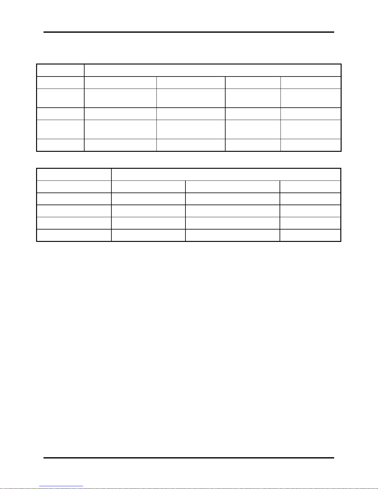
Table 1-1 HDD Specifications
Item
Capacity (GB) 120GB 160 GB 200 250 GB
Rotational
Speed (RPM)
Height 9.5 mm 9.5 mm 9.5 mm 9.5 mm
User Data
Sectors
Bytes / Sector
5400 or 7200 RPM 5400 or 7200 RPM 7200 RPM 5400 RPM
234,441,648 312,581,808 312,581,808 488,397,168
512 512 512 512
Specifications
Item
Capacity (GB)
Rotational Speed (RPM)
Height
User Data Sectors
Bytes / Sector 512 512 512
320G 320G 500 GB
5400 RPM 7200 RPM 5400 RPM
9.5 mm 9.5 mm 12.5 mm
625,142,448 625,142,448 976,773,168
Specifications
Satellite A500D Maintenance Manual 1-12
Error! Style not defined. Error! Style not defined. 1 Hardware Overview
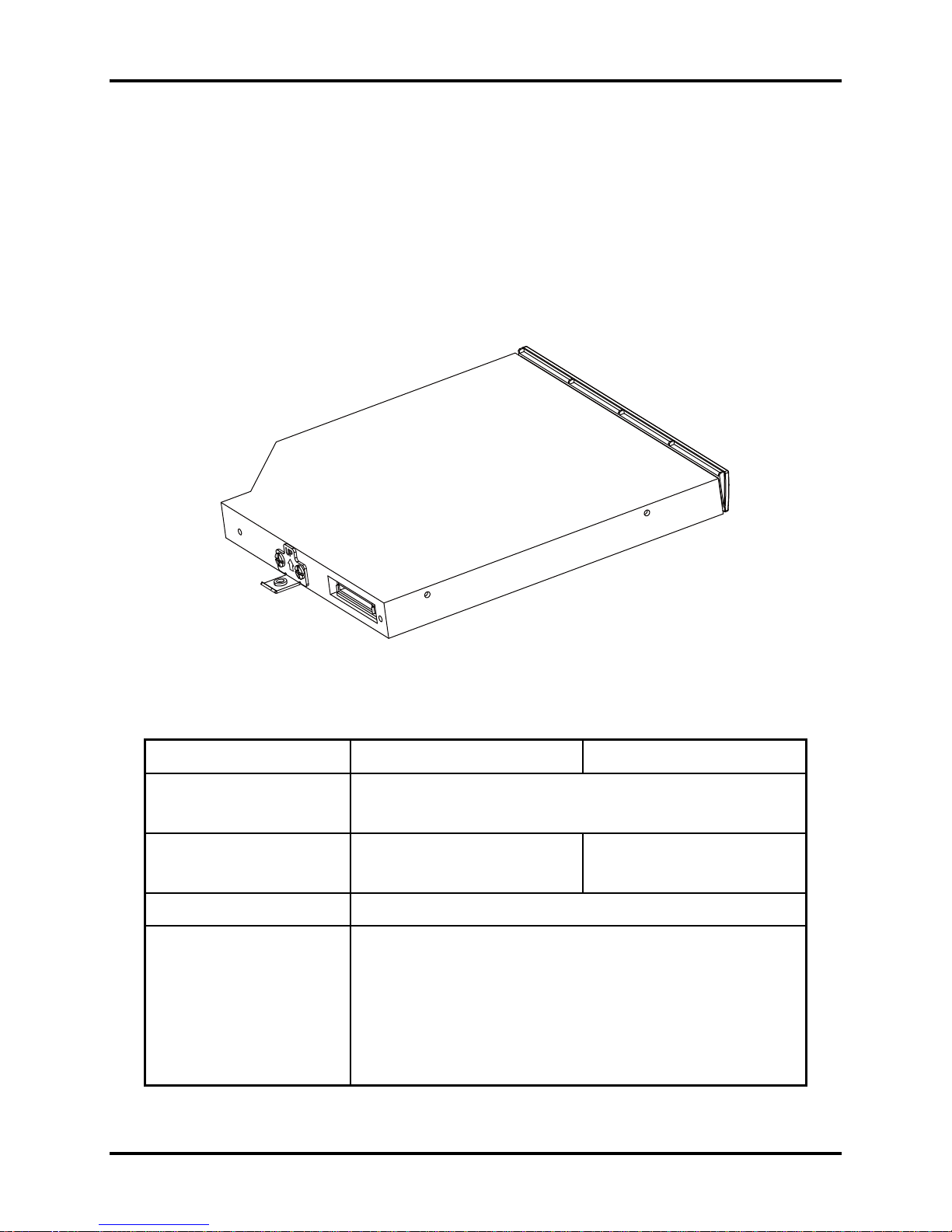
1.3 DVD Super Multi (+-R Double Layer)
The DVD Super Multi drive accepts 12-cm (4.72-inch) and 8-cm (3.15-inch) discs. At maximum,
the drive can play back a DVD at 8x speed, read CD-ROM at 24x speed, and write CD-R at 24x
speed, CD-RW at 6x speed, CD-RW at 16x speed, DVD-R at 8x speed, DVD-RW at 8x speed,
DVD+R at 8x speed, DVD+R (Double Layer) at 8x speed, DVD-R (Dual Layer) at 8x speed,
DVD+RW at 8x speed and DVD-RAM at 5x speed.
The DVD Super Multi drive is shown in Figure 1-3 and its specifications are listed in Table 1-2.
Figure 1-3 DVD Super Multi Drive
Table 1-2 DVD Super Multi Drive Specifications
Item DVD-ROM Mode CD-ROM Mode
33.3 (U-DMA transfer mode 2)
Data Transfer Rate (Mbytes/s)
16.6 (PIO mode 4, Multiword DMA mode 2)
Access Time (ms)
Average Random Access 130 130
Data Buffer Size (Mbytes) 2MB
DVD:
DVD-VIDEO, DVD-ROM, DVD-R, DVD-RW, DVD-RAM, DVD+R,
DVD+-R (Double Layer), DVD+RW.
Formats Supported
CD:
CD-DA, CD-ROM, CD-R, CD-RW, CD-ROMXA, Photo CD
(Multi-Session), Video CD, CD-Extra (CD+), CD-Text.
Satellite A500D Maintenance Manual 1-13
 Loading...