


TOSHIBA Satellite A210/
Satellite Pro A210
Portable Personal Computer
User’s Manual

Copyright
© 2007 by TOSHIBA Corporation. All rights reserved. Under the copyright
laws, this manual cannot be reproduced in any form without the prior written
permission of TOSHIBA. No patent liability is assumed, with respect to the use
of the information contained herein.
TOSHIBA Satellite A210/Satellite Pro A210 Portable Personal Computer User’s
Manual
First edition August 2007
Copyright authority for music, movies, computer programs, data bases and other
intellectual property covered by copyright laws belongs to the author or to the
copyright owner. Copyrighted material can be reproduced only for personal use or
use within the home. Any other use beyond that stipulated above (including conversion to digital format, alteration, transfer of copied material and distribution on
a network) without the permission of the copyright owner is a violation of copyright or author’s rights and is subject to civil damages or criminal action. Please
comply with copyright laws in making any reproduction from this manual.
Disclaimer
This manual has been validated and reviewed for accuracy. The instructions and
descriptions it contains are accurate for the TOSHIBA Satellite A210/Satellite
Pro A210 Portable Personal Computer at the time of this manual’s production.
However, succeeding computers and manuals are subject to change without
notice. TOSHIBA assumes no liability for damages incurred directly or indirectly from errors, omissions or discrepancies between the computer and the
manual.
Trademarks
IBM is a registered trademark, and IBM PC and PS/2 are trademarks of International Business Machines Corporation.
AMD, the AMD Arrow logo, AMD Athlon, AMD Turion, Radeon, and combinations thereof, ATI Mobility Radeon are trademarks of Advanced Micro Devices,
Inc.
Windows and Microsoft are registered trademarks and Windows Vista is a trademark of Microsoft Corporation.
Photo CD is a trademark of Eastman Kodak.
Memory Stick is a registered trademark and i.LINK is a trademark of SonyCorporation.
ii User’s Manual

Bluetooth is a registered trademark owned by its proprietor and used by
TOSHIBA under license.
DVD MovieFactory is trademarks of the Ulead Systems. Inc.
Labelflash™ is a trademark of YAMAHA CORPORATION.
Manufactured under license from Dolby Laboratories.
"Dolby" and the double-D symbol are trademarks of Dolby Laboratories.
Confidential unpublished works. Copyright 1992-1997 Dolby Laboratories.
All rights reserved.
Manufactured under license from Digital Theater Systems, Inc. U.S. Pat. No's.
5,451,942; 5,956,674; 5,974,380; 5,978,762; 6,226,616; 6,487,535 and other
U.S. and world-wide patents issued and pending. "DTS" and "DTS Digital Surround" are registered trademarks of Digital Theater Systems, Inc. Copyright
1996, 2003 Digital Theater Systems, Inc. All Rights Reserved.
Other trademarks and registered trademarks not listed above may be used in this
manual.
Macrovision License of Notice
This product incorporates copyright protection technology that is protected by
U.S. patents and other intellectual property rights. Use of this copyright protection technology must be authorized by Macrovision, and is intended for home
and other limited viewing uses only unless authorized by Macrovision. Reverse
engineering of disassembly is prohibited.
Safety Instructions
Use the following safety guidelines to help protect yourself and your computer.
When Using Your Computer
Do not operate your portable computer for an extended period of
time with the base resting directly on your body. With extended
operation, heat can potentially build up in the base. Allowing
sustained contact with the skin could cause discomfort or,
eventually, a burn.
❑ Do not attempt to service the computer yourself. Always follow installation
instructions closely.
❑ Do not carry a battery in your pocket, purse, or other container where metal
objects (such as car keys) could short-circuit the battery terminals. The
User’s Manual iii

resulting excessive current follow can cause extremely high temperatures
and may result in damage from burns.
❑ Be sure that noting rests on your AC adapter’s power cable and that the
cable is not located where it can be tripped over or stepped on.
❑ Place the AC adapter in a ventilated area, such as a desk top or on the floor,
when you use it to run the computer or to charge the battery. Do not cover
the AC adapter with papers or other items that will reduce cooling; also, do
not use the AC adapter while it is inside a carrying case.
❑ Use only the AC adapter and batteries that are approved for use with this
computer. Use of another type of battery or AC adapter may risk fire or
explosion.
❑ Before you connect the computer to a power source, ensure that the voltage
rating of the AC adapter matches that of the available power source. 115 V/
60 Hz in most of North and South America and some Far Eastern countries
such as Taiwan. 100 V/50 Hz in eastern Japan and 100 V/60 Hz in western
Japan. 230 V/50 Hz in most of Europe, the Middle East, and the Far East.
❑ If you use an extension cable with your AC adapter, ensure that the total
ampere rating of the products plugged in to the extension cable does not
exceed the ampere rating of the extension cable.
❑ To remove power from the computer, turn it off, remove the battery, and dis-
connect the AC adapter from the electrical outlet.
❑ To help avoid the potential hazard of electric shock, do not connect or dis-
connect any cables or perform maintenance or reconfiguration of this product during an electrical storm.
❑ When setting up the computer for work, place it on a level surface.
FCC information
FCC notice “Declaration of Conformity Information”
This equipment has been tested and found to comply with the limits for a Class B
digital device, pursuant to part 15 of the FCC rules. These limits are designed to
provide reasonable protection against harmful interference in a residential installation. This equipment generates, uses and can radiate radio frequency energy
and, if not installed and used in accordance with the instructions, may cause
harmful interference to radio communications. However, there is no guarantee
that interference will not occur in a particular installation. If this equipment does
cause harmful interference to radio or television reception, which can be deter-
iv User’s Manual

mined by turning the equipment off and on, the user is encouraged to try to correct the interference by one or more of the following measures:
❑ Reorient or relocate the receiving antenna.
❑ Increase the separation between the equipment and receiver.
❑ Connect the equipment into an outlet on a circuit different from that to
which the receiver is connected.
❑ Consult the dealer or an experienced radio/TV technician for help..
Only peripherals complying with the FCC class B limits may be
attached to this equipment. Operation with non-compliant
peripherals or peripherals not recommended by TOSHIBA is
likely to result in interference to radio and TV reception. Shielded
cables must be used between the external devices and the
computer’s external monitor port, USB port, and microphone
jack. Changes or modifications made to this equipment, not
expressly approved by TOSHIBA or parties authorized by
TOSHIBA could void the user’s authority to operate the
equipment.
FCC conditions
This device complies with part 15 of the FCC Rules. Operation is subject to the
following two conditions:
1. This device may not cause harmful interference.
2. This device must accept any interference received, including interference
that may cause undesired operation.
Contact
Address: TOSHIBA America Information Systems, Inc.
9740 Irvine Boulevard
Irvine, California 92618-1697
Telephone: (949) 583-3000
User’s Manual v
BSMI Notice (Taiwan Only)
EU Declaration of Conformity
Supplementary Information: “The product complies with the requirements
of the Low Voltage Directive 2006/95/EC,
the EMC Directive 89/336/EEC and/or the
R&TTE Directive 1999/5/EC.”
This product is carrying the CE-Mark in accordance with the related European
Directives. Responsible for CE-Marking is TOSHIBA Europe, Hammfelddamm
8, 41460 Neuss, Germany.
VCCI Class B Information
Canadian Regulatory Information
(Canada Onl y)
This digital apparatus does not exceed the Class B limits for radio noise emissions from digital apparatus as set out in the Radio Interference Regulation of the
Canadian Department of Communications.
Note that Canadian Department of Communications (DOC) regulations provide,
that changes or modifications not expressly approved by TOSHIBA Corporation
could void your authority to operate this equipment.
This Class B digital apparatus meets all requirements of the Canadian Interference-Causng Equipment Regulations.
vi User’s Manual

Cet appareil numérique de la class B respecte toutes les exgences du Règlement
sur le matériel brouileur du Canada.
Modem warning notice
Conformity Statement
The equipment has been approved to [Commission Decision “CTR21”] for panEuropean single terminal connection to the Public Switched Telephone Network
(PSTN).
However, due to differences between the individual PSTNs provided in different
countries/regions the approval does not, of itself, give an unconditional assurance of successful operation on every PSTN network termination point.
In the event of problems, you should contact your equipment supplier in the first
instance.
Network Compatibility Statement
This product is designed to work with, and is compatible with the following networks. It has been tested to and found to conform with the additional requirements conditional in EG 201 121.
Germany ATAAB AN005,AN006,AN007,AN009,AN010 and
DE03,04,05,08,09,12,14,17
Greece ATAAB AN005,AN006 and GR01,02,03,04
Portugal ATAAB AN001,005,006,007,011 and P03,04,08,10
Spain ATAAB AN005,007,012, and ES01
Switzerland ATAAB AN002
All other countries/region ATAAB AN003,004
Specific switch settings or software setup are required for each network, please
refer to the relevant sections of the user guide for more details.
The hookflash (timed break register recall) function is subject to separate
national type approvals. It has not been tested for conformity to national type
regulations, and no guarantee of successful operation of that specific function on
specific national networks can be given.
User’s Manual vii

Japan regulations
Region selection
If you are using the computer in Japan, technical regulations described in the
Telecommunications Business Law require that you select the Japan region
mode. It is illegal to use the modem in Japan with any other selection.
Redial
Up to two redial attempts can be made. If more than two redial attempts are
made, the modem will return
with the Black Listed code, set the interval between redials at one minute or
longer.
Japan’s Telecommunications Business Law permits up to two redials on analogue telephones, but the redials must be made within a total of three minutes.
The internal modem is approved by Japan Approvals Institute for Telecommunications Equipment.
Black Listed
. If you are experiencing problems
A05-0413001
Pursuant to FCC CFR 47, Part 68:
When you are ready to install or use the modem, call your local telephone company and give them the following information:
❑ The telephone number of the line to which you will connect the modem
❑ The registration number that is located on the device.
US: AGSMDO1BDELPHI
The FCC registration number of the modem will be found on either the
device which is to be installed, or, if already installed, on the bottom of the
computer outside of the main system label.
❑ The Ringer Equivalence Number (REN) of the modem, which can vary. For
the REN of your modem, refer to your modem’s label.
The modem connects to the telephone line by means of a standard jack called the
USOC RJ11C.
Type of service
Your modem is designed to be used on standard-device telephone lines. Connection to telephone company-provided coin service (central office implemented
viii User’s Manual

systems) is prohibited. Connection to party lines service is subject to state tariffs.
If you have any questions about your telephone line, such as how many pieces of
equipment you can connect to it, the telephone company will provide this information upon request.
Telephone company procedures
The goal of the telephone company is to provide you with the best service it can.
In order to do this, it may occasionally be necessary for them to make changes in
their equipment, operations, or procedures. If these changes might affect your
service or the operation of your equipment, the telephone company will give you
notice in writing to allow you to make any changes necessary to maintain uninterrupted service.
If problems arise
If any of your telephone equipment is not operating properly, you should immediately remove it from your telephone line, as it may cause harm to the telephone
network. If the telephone company notes a problem, they may temporarily discontinue service. When practical, they will notify you in advance of this disconnection. If advance notice is not feasible, you will be notified as soon as possible.
When you are notified, you will be given the opportunity to correct the problem
and informed of your right to file a complaint with the FCC. In the event repairs
are ever needed on your modem, they should be performed by TOSHIBA Corporation or an authorized representative of TOSHIBA Corporation.
Disconnection
If you should ever decide to permanently disconnect your modem from its
present line, please call the telephone company and let them know of this change.
Fax branding
The Telephone Consumer Protection Act of 1991 makes it unlawful for any person to use a computer or other electronic device to send any message via a telephone fax machine unless such message clearly contains in a margin at the top or
bottom of each transmitted page or on the first page of the transmission, the date
and time it is sent and an identification of the business, other entity or individual
sending the message and the telephone number of the sending machine or such
business, other entity or individual. In order to program this information into
your fax modem, you should complete the setup of your fax software before
sending messages.
User’s Manual ix
Instructions for IC CS-03 certified equipment
1 The Industry Canada label identifies certified equipment. This certification
means that the equipment meets certain telecommunications network protective, operational and safety requirements as prescribed in the appropriate
Terminal Equipment Technical Requirements document(s). The Department
does not guarantee the equipment will operate to the user’s satisfaction.
Before installing this equipment, users should ensure that it is permissible to
be connected to the facilities of the local telecommunications company. The
equipment must also be installed using an acceptable method of connection.
The customer should be aware that compliance with the above conditions
may not prevent degradation of service in some situations. Repairs to certified equipment should be coordinated by a representative designated by the
supplier. Any repairs or alterations made by the user to this equipment, or
equipment malfunctions, may give the telecommunications company cause
to request the user to disconnect the equipment.
Users should ensure for their own protection that the electrical ground connections of the power utility, telephone lines and internal metallic water pipe
system, if present, are connected together. This precaution may be particu-
larly important in rural areas.
Users should not attempt to make such connections themselves,
but should contact the appropriate electric inspection authority,
or electrician, as appropriate.
2 The user manual of analog equipment must contain the equipment’s Ringer
Equivalence Number (REN) and an explanation notice similar to the following:
The Ringer Equivalence Number (REN) of the modem, which can vary. For
the REN of your modem, refer to your modem’s label.
The Ringer Equivalence Number (REN) assigned to each terminal
device provides an indication of the maximum number of
terminals allowed to be connected to a telephone interface. The
termination on an interface may consist of any combination of
devices subject only to the requirement that the sum of the Ringer
Equivalence Numbers of all the devices does not exceed 5.
3 The standard connecting arrangement (telephone jack type) for this equip-
ment is jack type(s): USOC RJ11C.
The IC registration number of the modem is shown below.
x User’s Manual
Canada: 4005B-DELPHI

Notes for Users in Australia and New Zealand
Modem warning notice for Australia
Modems connected to the Australian telecoms network must have a valid Austel
permit. This modem has been designed to specifically configure to ensure compliance with Austel standards when the country/region selection is set to Australia. The use of other country/region setting while the modem is attached to the
Australian PSTN would result in you modem being operated in a non-compliant
manner. To verify that the country/region is correctly set, enter the command ATI
which displays the currently active setting.
To set the country/region permanently to Australia, enter the following command
sequence:
AT%TE=1
ATS133=1
AT &F
AT &W
AT%TE=0
AT Z
Failure to set the modem to the Australia country/region setting as shown above
will result in the modem being operated in a non-compliant manner. Consequently, there would be no permit in force for this equipment and the Telecoms
Act 1991 prescribes a penalty of $12,000 for the connection of non-permitted
equipment.
Notes for use of this device in New Zealand
❑ The grant of a Telepermit for a device in no way indicates Telecom accep-
tance of responsibility for the correct operation of that device under all operating conditions. In particular the higher speeds at which this modem is
capable of operating depend on a specific network implementation which is
only one of many ways of delivering high quality voice telephony to customers. Failure to operate should not be reported as a fault to Telecom.
❑ In addition to satisfactory line conditions a modem can only work properly
if:
(a) it is compatible with the modem at the other end of the call and
(b) the application using the modem is compatible with the application at
the other end of the call - e.g., accessing the Internet requires suitable
software in addition to a modem.
❑ This equipment shall not be used in any manner which could constitute a
nuisance to other Telecom customers.
User’s Manual xi

❑ Some parameters required for compliance with Telecom’s PTC Specifica-
tions are dependent on the equipment (PC) associated with this modem. The
associated equipment shall be set to operate within the following limits for
compliance with Telecom Specifications:
(a) There shall be no more than 10 call attempts to the same number within
any 30 minute period for any single manual call initiation, and
(b) The equipment shall go on-hook for a period of not less than 30 seconds
between the end of one attempt and the beginning of the next.
(c) Automatic calls to different numbers shall be not less than 5 seconds
apart.
❑ Immediately disconnect this equipment should it become physically dam-
aged, and arrange for its disposal or repair.
❑ The correct settings for use with this modem in New Zealand are as follows:
ATB0 (CCITT operation)
AT&G2 (1800 Hz guard tone)
AT&P1 (Decadic dialing make-break ratio = 33%/67%)
ATS0=0 (not auto answer)
ATS10=less than 150 (loss of carrier to hangup delay, factory default of 15
recommended)
ATS11=90 (DTMF dialing on/off duration=90 ms)
ATX2 (Dial tone detect, but not (U.S.A.) call progress detect)
❑ When used in the Auto Answer mode, the S0 register must be set with a
value of 3 or 4. This ensures:
(a) a person calling your modem will hear a short burst of ringing before
the modem answers. This confirms that the call has been successfully
switched through the network.
(b) caller identification information (which occurs between the first and
second ring cadences) is not destroyed.
❑ The preferred method of dialing is to use DTMF tones (ATDT...) as this is
faster and more reliable than pulse (decadic) dialing. If for some reason you
must use decadic dialing, your communications program must be set up to
record numbers using the following translation table as this modem does not
implement the New Zealand “Reverse Dialing” standard.
Number to be dialed: 0 1 2 3 4 5 6 7 8 9
Number to program into computer: 0 9 8 7 6 5 4 3 2 1
Note that where DTMF dialing is used, the numbers should be entered nor-
mally.
xii User’s Manual

❑ The transmit level from this device is set at a fixed level and because of this
there may be circumstances where the performance is less than optimal.
Before reporting such occurrences as faults, please check the line with a
standard Telepermitted telephone, and only report a fault if the phone performance is impaired.
❑ It is recommended that this equipment be disconnected from the Telecom
line during electrical storms.
❑ When relocating the equipment, always disconnect the Telecom line connec-
tion before the power connection, and reconnect the power first.
❑ This equipment may not be compatible with Telecom Distinctive Alert
cadences and services such as FaxAbility.
NOTE THAT FAULT CALLOUTS CAUSED BY ANY OF THE
ABOVE CAUSES MAY INCUR A CHARGE FROM TELECOM
General conditions
As required by PTC 100, please ensure that this office is advised of any changes
to the specifications of these products which might affect compliance with the
relevant PTC Specifications.
The grant of this Telepermit is specific to the above products with the marketing
description as stated on the Telepermit label artwork. The Telepermit may not be
assigned to other parties or other products without Telecom approval.
A Telepermit artwork for each device is included from which you may prepare
any number of Telepermit labels subject to the general instructions on format,
size and colour on the attached sheet.
The Telepermit label must be displayed on the product at all times as proof to
purchasers and service personnel that the product is able to be legitimately connected to the Telecom network.
The Telepermit label may also be shown on the packaging of the product and in
the sales literature, as required in PTC 100.
The charge for a Telepermit assessment is $337.50. An additional charge of
$337.50 is payable where an assessment is based on reports against non-Telecom
New Zealand Specifications. $112.50 is charged for each variation when submitted at the same time as the original.
An invoice for $NZ1237.50 will be sent under separate cover.
User’s Manual xiii
Following information is only for EU-member states:
The symbol indicates that this product may not be treated as
household waste. Please ensure this product is properly
disposed as inappropriate waste handling of this product may
cause potential hazards to the environment and human health.
For more detailed information about recycling of this
product, please contact your local city office, your household waste disposal service or the shop where you pur-
chased the product.
This symbol may not stick depending on the country and region
where you purchased.
Optical disc drive standards
TOSHIBA Satellite A210/Satellite Pro A210 computer is shipped with one
of the following drives preinstalled: DVD-ROM, CD-RW/DVD-ROM, or
DVD Super Multi (+-R DL) drive.
The drive has one of the following labels:
CLASS 1 LASER PRODUCT
LASER KLASSE 1
LUOKAN 1 LASERLAITE
APPAREIL A LASER DE CLASSE1
KLASS 1 LASER APPARAT
Before it is shipped, the Class 1 Laser is certified to meet the United States
Chapter 21 Standards of the Department of Health and Human Services
(DHHS 21 CFR).
For any other country, the drive is certified to meet the Class 1 Laser standards of IEC825 and EN60825.
xiv User’s Manual

Important Notice
Copyrighted works including, but not limited to music, video, computer program, databases are protected by copyright laws. Unless specifically permitted
under applicable copyright laws, you cannot copy, modify, assign, transmit or
otherwise dispose of any copyrighted work with the consent of the owner of the
copyright. Please take notice that unauthorized copying, modification, assignment, transmission and disposition may be subject to claims for damages and
penalties.
❑ Avoid using a telephone (other than a cordless type) during an electrical
storm. There may be a remote risk of electric shock from lightning.
❑ Do not use the telephone to report a gas leak in the vicinity of the leak.
❑ Use only the power cord indicated in this manual.
❑ Replace only with the same or equivalent type battery recommended by the
manufacturer.
❑ Dispose of used batteries according to the manufacturer’s instructions.
Use only the battery pack that came with the computer or an
optional battery pack. Use of wrong battery could damage your
computer.
TOSHIBA assumes no liability for any damage in such case.
User’s Manual xv
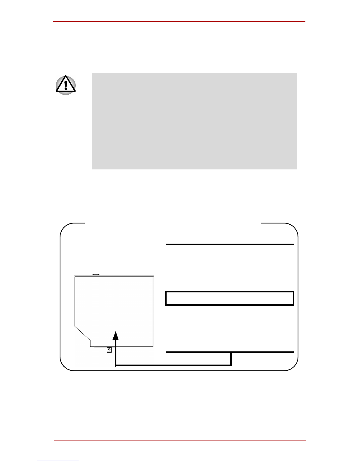
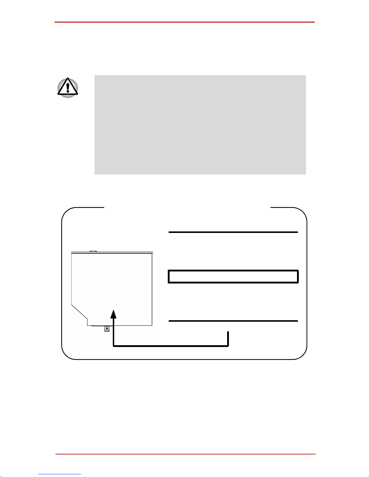
CD-RW/DVD-ROM drive safety
instructions
❑ The drive employs a laser system. To ensure proper use of this
product, please read this instruction manual carefully and
retain for future reference.
Should the unit ever require maintenance, contact an authorized service location.
❑ Use of controls, adjustments or the performance of proce-
dures other than those specified may result in hazardous radiation exposure.
❑ To prevent direct exposure to the laser beam, do not try to
open the enclosure.
Toshiba Samsung TS-L462D
Location of the required label
PRODUCT IS CERTIFIED BY THE
MANUFACTURER TO COMPLY WITH
DHHS RULES 21 CFR SUBCHAPTER
J APPLICABLE AT THE DATE OF
MANUFACTURE.
MANUFACTURED:
Toshiba Samsung Strage Technology
Korea corporation
416, Maetan-3Dong, Yeongtong-Gu
Suwon City, Gyeonggi-Do, 443-742,
Korea
xvi User’s Manual

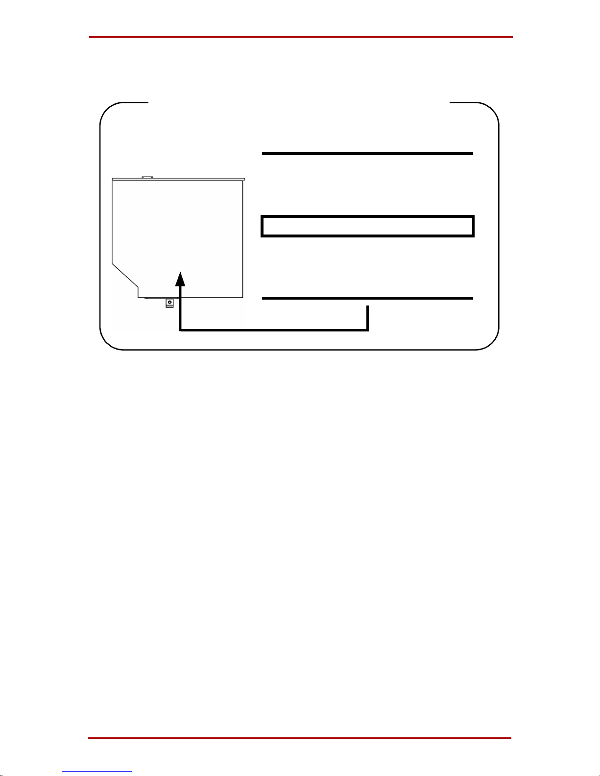
TEAC DW-224E
Location of the required label
CERTIFICATION TISH PRODUCT
COMPLIES WITH DHHS RULES21CFR
CHAPTER 1, SUBCHAPTER J APPLICABLE DATE OF MANUFACTURE
MANUFACTURED:
TEAC CORPORATION
3-7-3 NAKA-CHO, MUSASHINO-SHI,
TOKYO, JAPAN
User’s Manual xvii
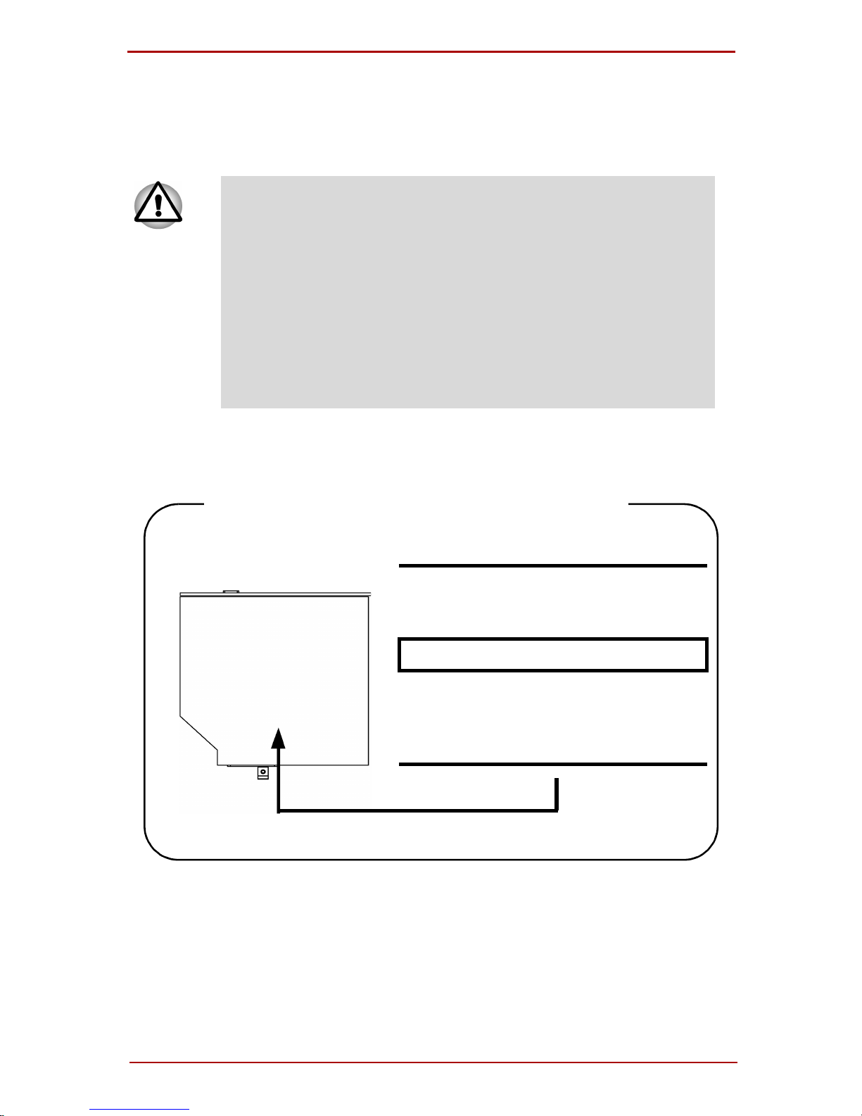
HD DVD-ROM and HD DVD-R drive
safety instructions
❑ The drive employs a laser system. To ensure proper use of this
product, please read this instruction manual carefully and
retain for future reference.
Should the unit ever require maintenance, contact an authorized service location.
❑ Use of controls, adjustments or the performance of proce-
dures other than those specified may result in hazardous radiation exposure.
❑ To prevent direct exposure to the laser beam, do not try to
open the enclosure.
Toshiba TS-L802A
Location of the required label
PRODUCT IS CERTIFIED BY THE
MANUFACTURER T O COMP AL WITH
DHHS RULES 21 CFR CHAPTER1,
SUBCHAPTER J.
MANUFACTURED:
Manufactured by
TOSHIBA CORPORATION
1-1, SHIBAURA 1-CHOME, MINATO KU, TOKYO 105-8001, JAPAN
xviii User’s Manual
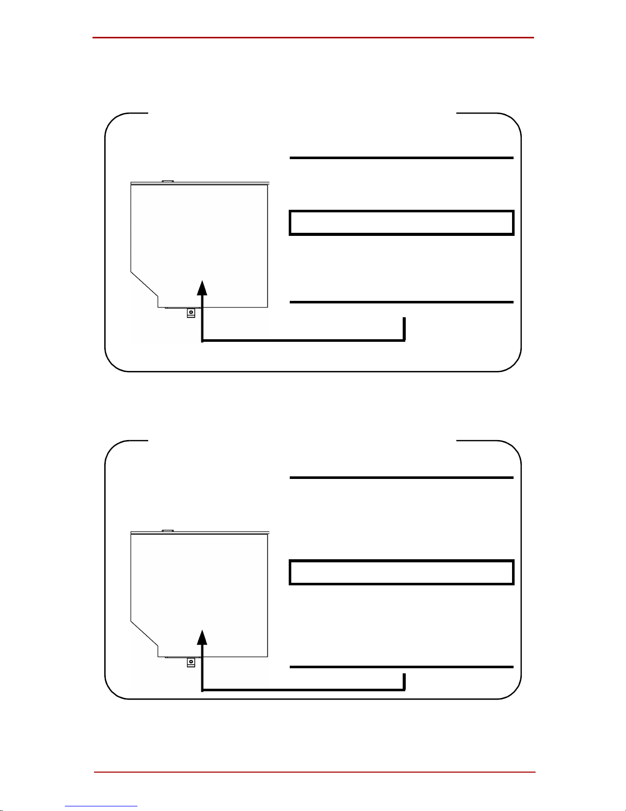
Toshiba SD-L902A
Location of the required label
PRODUCT IS CERTIFIED BY THE
MANUFACTURER T O COMPAL WITH
DHHS RULES 21 CFR CHAPTER1,
SUBCHAPTER J.
MANUFACTURED:
Manufactured by
TOSHIBA CORPORATION
1-1, SHIBAURA 1-CHOME, MINATOKU, TOKYO 105-8001, JAPAN
User’s Manual xix
DVD Super Multi (+-R DL) drive safety
instructions
❑ The drive employs a laser system. To ensure proper use of this
product, please read this instruction manual carefully and
retain for future reference.
Should the unit ever require maintenance, contact an authorized service location.
❑ Use of controls, adjustments or the performance of proce-
dures other than those specified may result in hazardous radiation exposure.
❑ To prevent direct exposure to the laser beam, do not try to
open the enclosure.
Matsushita UJ-850U
Location of the required label
COMPLIES WITHFDA RADIATION
PERFORMANCE STANDARDS, 21
CFR SUBCHAPTER J.
MANUFACTURED:
Manufactured by
Panasonic Communications Co.,
LTD 1-62, 4-Chome, Minoshima,
Hakata-ku, Fukuoka, JAPAN
xx User’s Manual

TEAC DV-W28E
Location of the required label
CERTIFICATION TISH PRODUCT
COMPLIES WITH DHHS RULES 21
CFR CHAPTER 1, SUBCHAPTER J
APPLICABLE DATE OF MANUFACTURE
MANUFACTURED:
TEAC CORPORATION
3-7-3 NAKA-CHO, MUSASHINO-SHI,
TOKYO, JAPAN
HLDS GSA-T20N
Location of the required label
COMPLIES WITHFDA RADIATION
PERFORMANCE STANDARDS, 21
CFR SUBCHAPTER J.
MANUFACTURED:
Manufactured by
Panasonic Communications Co.,
LTD 1-62, 4-Chome, Minoshima,
Hakata-ku, Fukuoka, JAPAN
User’s Manual xxi
Pioneer DVR-K17T
Location of the required label
COMPLIES WITHFDA RADIATION
PERFORMANCE STANDARDS, 21
CFR SUBCHAPTER J.
MANUFACTURED:
Manufactured by
PIONEER CORPORATION 4-1.
Meguro 1-chome, Meguro-ku
TOKYO 153-8654, JAPAN
Toshiba Samsung TS-L632D
Location of the required label
PRODUCT IS CERTIFIED BY THE
MANUFACTURER TO COMPLY WITH
DHHS RULES 21 CFR SUBCHAPTER
J APPLICABLE AT THE DATE OF
MANUFACTURE.
MANUFACTURED:
TOSHIBA SAMSUNG STORAGE
TECHNOLOGY CORPORATION 580,
HORIKAWA-CHO, SAIWAI-KU,
KAWASAKI-SHI, KANAGAWA, 2120013, JAPAN
xxii User’s Manual
CLASS 1 LASTER PRODUCT
LASERSCHUTZKLASSE 1
PRODUKT
TO EN 60825
CAUTION: This appliance contains a laser
system and is classified as a “CLASS 1 LASER
PRODUCT.” To use this model properly, read
the instruction manual carefully and keep this
manual for your future reference. In case of any
trouble with this model, please contact your
nearest “AUTHORIZED service station.” To
prevent direct exposure to the laser beam, do
not try to open the enclosure.
VORSICHT: Dieses Gerät enthält ein Laser-
System und ist als “LASERSCHUTZKLASSE 1
PRODUKT” klassifiziert. Für den richtigen
Gebrauch dieses Modells lesen Sie bitte die
Bedienungsanleitung sorgfältig durch und
bewahren diese bitte als Referenz auf. Falls
Probleme mit diesem Modell auftreten, benachrichtigen Sie bitte die nächste “autorisierte
Service-Vertretung”. Um einen direkten Kontakt mit dem Laserstrahl zu vermeiden darf das
Gerät nicht geöffnet werden.
ADVERSEL: USYNLIG
LASERSTRÅLING VED ÅBNING,
NÅR SIKKERHEDSAF-BRYDER
ER UDE AF FUNKTION.
UNDGÅ UDSÆTTELSE FOR
STRÅLING
ADVARSEL: Denne męrking er anbragt udv-
endigt på apparatet og indikerer, at apparatet
arbejder med laserstråler af klasse 1, hviket
betyder, at der anvendes laserstrlier afsvageste
klasse, og at man ikke på apparatets yderside
kan bilve udsat for utilladellg kraftig stråling.
APPARATET BOR KUN ÅBNES AF FAGFOLK
MED SĘRLIGT KENDSKAB TIL APPARATER
MED LASERSTRÅLER!
Indvendigt i apparatet er anbragt den her gengivne advarselsmękning, som advarer imod at
foretage sådanne indgreb i apparatet, at man
kan komme til at udsętte sig for laserstråling.
User’s Manual xxiii

OBS! Apparaten innehåller laserkomponent som
avger laserstråining överstigande gränsen för
laserklass 1.
VAROITUS. Suojakoteloa si saa avata. Laite
sisältää laserdiodin, joka lähetää näkymätöntä
silmilie vaarallista lasersäteilyä.
CAUTION: USE OF CONTROLS OR ADJUST-
MENTS OR PERFORMANCE OF PROCEDURES OTHER THAN THOSE SPECIFIED IN
THE OWNER’S MANUAL MAY RESULT IN
HAZARDOUS RADIATION EXPOSURE.
VORSICHT: DIE VERWENDUNG VON
ANDEREN STEURUNGEN ODER EINSTELLUNGEN ODER DAS DURCHFÜHREN VON
ANDEREN VORGÄNGEN ALS IN DER BEDIENUNGSANLEITUNG BESCHRIEBEN KÖNNEN GEFÄHRLICHE
STRAHLENEXPOSITIONEN ZUR FOLGE
HABEN.
xxiv User’s Manual

Table of Contents
Preface
Manual contents................................. ..... .....................xxxiii
Conventions .................................................................xxxiv
Abbreviations..............................................................xxxiv
Icons...........................................................................xxxiv
Keys............................................................................xxxiv
Key operation..................... ..... .....................................xxxv
Display.........................................................................xxxv
Messages ....................................................................xxxv
Terminology.................................................................xxxv
General Precautions
Creating a computer-friendly environment ..............xxxvii
Stress injury................................................................xxxvii
Heat injury ..................................................................xxxviii
Pressure or impact damage......................................xxxviii
Express Card overheating ........................................xxxviii
Mobile phone..............................................................xxxviii
Instruction Manual for safety and Comfort .............xxxviii
Chapter 1 Introduction
Equipment checklist........................................................1-1
Hardware.......................................................................1-1
Software.........................................................................1-2
Features............................................................................1-3
Processor.......................................................................1-3
Memory..........................................................................1-3
Disks..............................................................................1-4
Special Features ............................................................1-11
TOSHIBA Value Added Package ..................................1-13
Utilities and Application................................................1-14
User’s Manual xxv

Options ...........................................................................1-17
Chapter 2 The Grand Tour
Front with the display closed .........................................2-1
Left side .................. ..... ..... ..................................... ..... ......2-3
Right side................................... ..... .... ..... .........................2-6
Back side..........................................................................2-7
Underside .........................................................................2-8
Front with the display open............................................2-9
AV Button.....................................................................2-11
System indicators ................................. ..... ..................2-12
Optical disc drive...........................................................2-14
About the HD DVD.......................................................2-14
Region codes for DVD drives and media.....................2-15
Writable discs ..............................................................2-16
CD-RW/DVD-ROM drive .............................................2-18
DVD Super Multi (+-R DL) drive ..................................2-19
HD DVD ROM drive..................... .... ..... .......................2-20
HD DVD-R drive ..........................................................2-21
Remote Controller..........................................................2-22
Using the Remote Controller .......................................2-26
Installing/Removing batteries.......................................2-27
Installing the batteries..................................................2-28
Replacing the batteries................................................2-30
AC adaptor.......................................... ............................2-31
Chapter 3 Getting Started
Connecting the AC adaptor ............................................3-2
Opening the display.........................................................3-3
Turning on the power ......................................................3-3
Starting up for the first time............................................3-4
Turning off the power......................................................3-4
Shut Down mode (Boot mode) ......................................3-4
Hibernation mode..........................................................3-5
Starting Hibernation.......................................................3-6
Automatic Hibernation...................................................3-6
xxvi User’s Manual

Sleep mode....................................................................3-7
Restarting the computer ................................. ................3-8
System Recovery Options ..............................................3-9
System Recovery Options.............................................3-9
Create Optical Recovery Discs.....................................3-10
For HDD Recovery model..................... ..... ..................3-10
Restoring the preinstalled software from the Recovery
HDD .................................................................................3-10
Restoring the preinstalled software from your creating
Recovery Media..............................................................3-11
Chapter 4 Operating Basics
Using the Touch Pad/Dual Mode Pad ............................4-1
Dual Mode Pad Button function .....................................4-2
Using the Fingerprint Sensor .........................................4-3
Points to note about the Fingerprint Sensor..................4-4
Points to note about the Fingerprint Utility.....................4-6
Set Up Procedure..........................................................4-6
Windows Logon via Fingerprint Authentication..............4-8
Fingerprint System Boot Authentication ........................4-9
Fingerprint Single Sign-On Feature.............................4-10
How to Swipe the Finger..............................................4-11
Using optical disc drives...............................................4-12
Loading discs............................................................... 4-13
Removing discs ...........................................................4-15
AV Button function.......................................................4-16
Using TOS H IBA HD DVD PLAYER to en jo y HD DVDs4-17
HD DVD Playback Restrictions....................................4-17
Notes on use............................................................ ....4-17
Notes on playing HD DVD Video discs........................4-18
TOSHIBA HD DVD PLAYER.......................................4-20
Using TOSHIBA HD DVD PLAYER ...............................4-20
Starting TOSHIBA HD DVD PLAYER..........................4-20
Operating TOSHIBA HD DVD PLAYER ......................4-21
Open TOSHIBA HD DVD PLAYER HELP...................4-23
TOSHIBA HD DVD PLAYER Control window.............4-23
User’s Manual xxvii

Using the Computer in place of an HD DVD Player....4-26
Before Connecting.......................................................4-26
Connecting to the Computer........................................4-27
Switching between Computer and Television Display.4-27
Display Compatibility ....................................................4-28
Writing CDs on CD-RW/DVD-ROM drive......................4-29
Important message (CD-RW/DVD-ROM drive)...........4-29
Before writing or rewriting............................................4-29
When writing or rewriting.............................................4-30
Disclaimer (CD-RW/DVD-ROM drive).........................4-31
Writing CD/DVDs on DVD Su per Multi (+-R DL) drive.4-31
Important message (DVD Super Multi (+-R DL) drive) 4-31
Before writing or rewriting............................................4-31
When writing or rewriting.............................................4-34
Disclaimer (DVD Super Multi (+-R DL) drive)..............4-35
Writing CD/DVD/HD DVDs on HD DVD-R drives..........4-35
When writing or rewriting.............................................4-39
TOSHIBA Disc Creator................................................4-40
Data Verification ..........................................................4-42
Video............................................................................4-42
When using Ulead DVD MovieFactory® for TOSHIBA:...442
Media care ........................................................ ..............4-46
CD/DVD/HD DVD................................. ..... .... ..............4-46
Using the software.......................................................4-48
Using the microphone...................................................4-49
Modem ............................................................................4-50
Region selection..........................................................4-50
Properties menu..........................................................4-51
Wireless communications.............................................4-53
Wireless LAN..................... ..... .....................................4-53
LAN..................................................................................4-56
Connecting LAN cable.................................................4-56
Disconnecting LAN cable.............................................4-57
Cleaning the computer..................................................4-58
xxviii User’s Manual

Moving the computer.....................................................4-58
Heat dispersal ................................................................4-59
Chapter 5 The Keyboard
Typewriter keys................................................................5-1
F1 ... F12 function keys ...................................................5-2
Soft keys: FN key combinations.....................................5-2
Emulating keys on enhanced keyboard.........................5-2
Hot keys.........................................................................5-3
FN Sticky key.......................... ..................................... ..5-6
Windows special keys.....................................................5-7
Keypad overlay ................................................................5-7
Turning on the overlays .................................................5-7
Arrow mode ...................................................................5-7
Numeric mode ...............................................................5-8
Temporarily using normal keyboard (overlay on) ..........5-8
Temporarily using overlay (overlay off).......... ..... ..... .... ..5-9
Temporarily changing modes ........................................5-9
Generating ASCII characters ..........................................5-9
Chapter 6 Power and Power-Up Modes
Power conditions.............................................................6-1
Power indicators..............................................................6-3
Battery indicator.............................................................6-3
DC IN indicator ..............................................................6-3
Power indicator..................................... .........................6-4
Battery types............................. ..... .... ..............................6-4
Battery ...........................................................................6-4
Real time clock battery ..................................................6-5
Care and use of the battery pack ...................................6-6
Safety precautions.........................................................6-6
Charging the batteries ...................................................6-9
Monitoring battery capacity..........................................6-11
Maximizing battery operating time...............................6-12
Retaining data with power off ......................................6-13
Extending battery life...................................................6-13
User’s Manual xxix

Replacing the battery pack ...........................................6-14
Removing the battery pack..........................................6-14
Installing the battery pack............................................6-16
Starting the computer by password.............................6-16
Power-up modes..........................................................6-17
Windows utilities..........................................................6-17
Hot keys....................................................................... 6-17
Panel power on/off.......................................................6-18
System Auto Off...................... ..... .... ............................6-18
Chapter 7 HW Setup and Passwords
HW Setup..........................................................................7-1
Accessing HW Setup.....................................................7-1
HW Setup window .........................................................7-1
Chapter 8 Optional Devices
Cards/memory...............................................................8-1
Power devices ............................. .... ..... .........................8-1
Peripheral devices.........................................................8-1
Other..............................................................................8-1
Express Card....................................................................8-2
Installing an Express Card.............................................8-2
Removing an Express Card...........................................8-3
Multiple Digital Media Card Slot .....................................8-4
Installing a SD/SDHC/MS/MS Pro/MMC/xD card..........8-4
Removing a SD/SDHC/MS/MS Pro/MMC/xD card........8-6
Memory expansion ................... ..... .... ..............................8-7
Installing memory module..............................................8-7
Removing memory module............................................8-9
Additional battery pack (6 Cell and 9 Cell)..................8-10
Additional AC adaptor...................................................8-10
USB FDD Kit ...................................................................8-10
External monitor ............................................................8-11
Television .......................................................................8-12
HDMI................................................................................8-13
i.LINK (IEEE1394)...........................................................8-14
xxx User’s Manual

Precautions..................................................................8-14
Connecting...................................................................8-15
Disconnecting..............................................................8-16
Security lock ................................................................8-16
Chapter 9 Troubleshooting
Problem solving process................................................9-1
Preliminary checklist......................................................9-1
Analyzing the problem ...................................................9-2
Hardware and system checklist .....................................9-3
System start-up.................. ..... ..... ..................................9-3
Self test................ ..... ..... .... ...................................... .... ..9-4
Power.............................................................................9-4
Password.......................................................................9-7
Keyboard .......................................................................9-7
LCD panel......................................................................9-8
Hard disk drive...............................................................9-8
CD-RW/DVD-ROM drive ...............................................9-9
HD DVD ROM drive..................... .... ..... .......................9-10
HD DVD-R drive ..........................................................9-11
DVD Super Multi (+-R DL) drive ..................................9-12
Diskette drive ..............................................................9-14
Infrared port.................................................................9-14
Pointing device ............................................................9-14
Touch Pad/Dual Mode Pad..........................................9-15
USB mouse..................................................................9-17
Fingerprint Sensor....................................................... 9-18
Express Card...............................................................9-19
SD/SDHC/MS/MS Pro/MMC/xD card..........................9-19
Monitor.........................................................................9-20
Sound system..............................................................9-21
TV output signal........................................................... 9-21
USB .............................................................................9-22
Modem.........................................................................9-22
Sleep/Hibernation........................................................9-24
LAN..............................................................................9-24
User’s Manual xxxi

Wireless LAN..................... ..... .....................................9-24
Bluetooth......................................................................9-25
i.LINK (IEEE1394)..................................... .... ..... .........9-25
Recovery Discs...................... ..... .... ............................9-26
TOSHIBA support ..........................................................9-27
Before you call.............................................................9-27
Chapter 10 Disclaimers
CPU .................................................................................10-1
Memory (Main System).................. .... ............................10-2
Battery Life................................ .....................................10-2
HDD Drive Capacity.......................................................10-3
LCD..................................................................................10-3
Graphics Processor Unit ("GPU") ................................10-3
Wireless LAN..................................................................10-4
Non-applicable Icons.....................................................10-4
Copy Protection.............................................................10-4
Images.............................................................................10-4
LCD Brightness and Eye Strain....................................10-4
Appendixes
Appendix A
Specifications..................................................................A -1
Appendix B
Display Controller and Modes .......................................B-1
Appendix C
V.90/V.92..........................................................................C-1
Appendix D
Wireless LAN...................................................................D-1
Appendix E
AC Power Cord and Connectors................................... E-1
Glossary
Abbreviations..................................................... Glossary-1
Index
xxxii User’s Manual

Preface
Congratulations on your purchase of the TOSHIBA Satellite A210/Satellite Pro
A210 computer. This powerful, lightweight notebook computer is designed to
provide years of reliable, high-performance computing.
This manual tells how to set up and begin using your Satellite A210/Satellite Pro
A210 computer. It also provides detailed information on configuring your computer, basic operations and care, using optional devices and troubleshooting.
If you are a new user of computers or if you’re new to portable computing, first
read over the Introduction and The Grand Tour chapters to familiarize yourself
with the computer’s features, components and accessory devices. Then read Get-
ting Started for step-by-step instructions on setting up your computer.
If you are an experienced computer user, please continue reading the preface to
learn how this manual is organized, then become acquainted with this manual by
browsing through its pages. Be sure to look over the Special Features section of
the Introduction, to learn about features that are uncommon or unique to the
computers and carefully read HW Setup and Passwords. If you are going to
install Express Cards or connect external devices such as a printer, be sure to
read Chapter 8, Optional Devices.
Manual contents
This manual is composed of ten chapters, five appendixes, a glossary, and an
index.
Chapter 1, Introduction, is an overview of the computer’s features, capabilities,
and options.
Chapter 2, The Grand Tour, identifies the components of the computer and
briefly explains how they function.
Chapter 3, Getting Started, provides a quick overview of how to begin operating
your computer.
Chapter 4, Operating Basics, includes tips on care of the computer and on using
the Touch Pad/Dual Mode Pad, optical disc drive, external diskette drive, Wireless LAN, LANs, Audio/Video controls, and internal modem.
Chapter 5, The Keyboard, describes special keyboard functions including the
keypad overlay and hot keys.
User’s Manual xxxiii

Preface
Chapter 6, Power and Power-Up Modes, gives details on the computer’s power
resources and battery save modes.
Chapter 7, HW Setup and Passwords, explains how to configure the computer
using the HW Setup program. It also tells how to set a password.
Chapter 8, Optional Devices, describes the optional hardware available.
Chapter 9, Troubleshooting, provides helpful information on how to perform
some diagnostic tests, and suggests courses of action if the computer doesn’t
seem to be working properly.
Chapter 10, Disclaimers, states the Disclaimer(s) information applicable to
TOSHIBA computer.
The Appendixes provide technical information about your computer.
The Glossary defines general computer terminology and includes a list of acro-
nyms used in the text.
The Index quickly directs you to the information contained in this manual.
Conventions
This manual uses the following formats to describe, identify, and highlight terms
and operating procedures.
Abbreviations
On first appearance, and whenever necessary for clarity, abbreviations are
enclosed in parentheses following their definition. For example: Read Only
Memory (ROM). Acronyms are also defined in the Glossary.
Icons
Icons identify ports, dials, and other parts of your computer. The indicator panel
also uses icons to identify the components it is providing information on.
Keys
The keyboard keys are used in the text to describe many computer operations. A
distinctive typeface identifies the key top symbols as they appear on the key-
board. For example, ENTER identifies the Enter key.
xxxiv User’s Manual

Preface
Key operation
Some operations require you to simultaneously use two or more keys. We identify such operations by the key top symbols separated by a plus sign (+). For
example, CTRL + C means you must hold down CTRL and at the same time
press C. If three keys are used, hold down the first two and at the same time press
the third.
ABC When procedures require an action such as clicking an icon or entering
text, the icon’s name or the text you are to type in is represented in the
type face you see to the left.
Display
ABC
Names of Windows or icons or text generated by the computer that
appears on its display screen is presented in the type face you see to the
left.
Messages
Messages are used in this manual to bring important information to your attention. Each type of message is identified as shown below.
Pay attention! A caution informs you that improper use of
equipment or failure to follow instructions may cause data loss or
damage your equipment.
Please read. A note is a hint or advice that helps you make best
use of your equipment.
Terminology
This term is defined in this document as follows:
Start
User’s Manual xxxv
The word “Start” refers to the “ ” button in Microsoft® Windows
Vista™.

Preface
xxxvi User’s Manual

General Precautions
TOSHIBA computers are designed to optimize safety, minimize strain and withstand the rigors of portability. However, certain precautions should be observed
to further reduce the risk of personal injury or damage to the computer.
Be certain to read the general precautions below and to note the cautions
included in the text of the manual.
Creating a computer-friendly environment
Place the computer on a flat surface that is large enough for the computer and
any other items you are using, such as a printer.
Leave enough space around the computer and other equipment to provide adequate ventilation. Otherwise, they may overheat.
To keep your computer in prime operating condition, protect your work are from:
❑ Dust, moisture, and direct sunlight
❑ Equipment that generates a strong electromagnetic field, such as stereo
speakers (other than speakers that are connected to the computer) or speakerphones.
❑ Rapid changes in temperature or humidity and some sources of temperature
change such as air conditioner vents or heaters.
❑ Extreme heat, cold, or humidity.
❑ Liquids and corrosive chemicals.
Stress injury
Carefully read the Instruction Manual for Safety & Comfort. It contains informa-
tion on prevention of stress injuries to your hands and wrists that can be caused
by extensive keyboard use.
User’ s Manual xxxvii

General Precautions
Heat injury
❑ Avoid prolonged physical contact with the computer. If the computer is used
for long periods, its surface can become very warm. While the temperature
will not feel hot to the touch, if you maintain physical contact with the computer for a long time, for example if you rest the computer on your lap or if
you keep your hands on the palm rest, your skin might suffer low-heat
injury.
❑ If the computer has been used for a long time, avoid direct contact with the
metal plate supporting the various interface ports as this can become hot.
❑ The surface of the AC adaptor can become hot when in use but this condi-
tion does not indicate a malfunction. If you need to transport the AC adaptor,
you should disconnect it and let it cool before moving it.
❑ Do not lay the AC adaptor on a material that is sensitive to heat as the mate-
rial could become damaged.
Pressure or impact damage
Do not apply heavy pressure to the computer or subject it to any form of strong
impact as this can damage the computer’s components or otherwise cause it to
malfunctions.
Express Card overheating
Some Express Cards can become hot during prolonged use which may result in
errors or instability in the operation of the device in question. In addition, you
should also be careful when you remove an Express Card that has been used for a
long time.
Mobile phone
Please be aware that use of mobile phones can interface with the audio system.
The operation of the computer will not be impared in any way, but it is recommended that a minimum distance of 30cm is maintained between the computer
and a mobile phone that is in use.
Instruction Manual for safety and Comfort
All important information on the safe and proper use of this computer is
described in the enclosed Instruction Manual for Safety Comfort. Be sure to read
it before using the compute
xxxviii User’s Manual

Chapter 1
Introduction
This chapter provides an equipment checklist, and it identifies the computer’s
features, options and accessories.
Some of the features described in this manual may not function
properly if you use an operating system that was not pre- installed
by TOSHIBA.
Equipment checklist
Carefully unpack your computer. Save the box and packing materials for future
use.
I
NTRODUCTIO N
Hardware
Check to make sure you have all the following items:
❑ Satellite A210/Satellite Pro A210 Portable Personal Computer
❑ Universal AC adaptor and power cord
❑ Modular cable (Provided with some models)
User’s Manual 1-1

Introduction
Software
Windows Vista™
◆ The following software is preinstalled:
®
•Microsoft
Windows Vista™
NTRODUCTION
I
• Modem Driver (Can be used only for Modem models)
• Display Drivers for Windows
• Wireless LAN driver (Can be used only for Wireless LAN models)
• Sound Driver for Windows
• TOSHIBA DVD Player (Is pre-installed with CD-RW/DVD-ROM drive
model or DVD Super Multi drive model)
• TOSHIBA HD DVD Player (Is pre-installed with HD DVD-ROM drive
model or HD DVD-R drive model)
•LAN Drivers
• Bluetooth Driver (Can be used only for Bluetooth models)
• Pointing Device Driver
• TOSHIBA Power Saver
• TOSHIBA User’s Manual
• TOSHIBA Assist
• TOSHIBA ConfigFree
• TOSHIBA PC Diagnostic Tool
• TOSHIBA Zooming Utility
• TOSHIBA CD/DVD Drive Acoustic Silencer
• TOSHIBA Disc Creator
• Ulead DVD MovieFacotry
®
for TOSHIBA
• Fingerprint utility (Can be used only for Fingerprint utility models)
• TOSHIBA SD Memory Utilities
SD Memory Card Format Utility and other SD functions are
packaged into TOSHIBA SD Memory Utilities. When uninstalling
the SD utilities, click Start
→
Control Panel → Uninstall a
program, and select TOSHIBA SD Memory Utilities.
1-2 User’s Manual

◆ Documentation:
Introduction
• User Information Guide
•Microsoft
els)
• Instruction Manual for Safety & Comfort
• End User License Agreement
®
Windows Vista™ manual package (provided with some mod-
Features
This computer incorporates the following features and benefits:
Processor
Built-in Please visit your region’s website for the configuration
details of the model that you have purchased.
Memory
Slots PC2-4200 or PC2-5300 512 MB, 1024 MB or 2048 MB
memory modules can be installed in the two memory
slots.Maximum system memory size is depending on
the model you purchased.
I
NTRODUCTION
Video RAM Integrated Video Memory in graphic chip by ATI
Radeon™ X1200, up to 256MB shared with main
memory.(for more than 1GB main memory)
User’s Manual 1-3

Introduction
Disks
Hard disk drive The computer has an integrated, 2 1/2" hard disk drive
(HDD) for nonvolatile storage of data and software. It
comes in the following sizes.
60 GB
NTRODUCTION
I
CD-RW/DVD-
ROM drive
80 GB
100 GB
120 GB
160 GB
200 GB
250 GB
300 GB
Disclaimer (Hard disk drive capacity)
For more information on the Disclaimer regarding Hard
disk drive capacity, please refer to the Disclaimer section in chapter 10.
Some models are equipped with a full-size, CD-RW/
DVD-ROM drive module that lets you run CD/DVDs
without using an adaptor. It reads DVD-ROMs at maximum 8 speed and CD-ROMs at maximum 24 speed. It
writes CD-R at up to 24 speed and CD-RW at up to 24
speed. See Chapter 4, Operating Basics, for details. For
reading, this drive supports the same formats as the
DVD-ROM drive.
1-4 User’s Manual

Introduction
DVD Super Multi
(+-R DL) drive
Some models are equipped with a full-size DVD Super
Multi (+- R DL) drive module that lets you record data
to rewritable CD/DVDs as well as run either 12 cm
(4.72") or 8 cm (3.15") CD/DVDs without using an
adaptor. It reads DVD-ROMs at maximum 8 speed and
CD-ROMs at maximum 24 speed. It writes CD-R at up
to 24 speed, CD-RW at up to 16 speed, DVD-R at up to
8 speed and DVD-RW at maximum 6 speed and DVDRAM at maximum 5 speed. DVD+R at up to 8 speed
and DVD+RW at up to 8 speed. DVD+R DL at up to 4
speed and DVD-R DL at up to 4 speed. This drive supports the same formats as the DVD-ROM drive.
• DVD-ROM • DVD-Video
• DVD-R • DVD-RW
• DVD+R • DVD+RW
• DVD-RAM
• DVD+R DL
I
NTRODUCTION
• DVD-R DL
• CD-DA • CD-Text
• Photo CD (single/multi-session)
• CD-ROM Mode 1, Mode 2
• CD-ROMXA Mode 2 (Form1, Form2)
• Enhanced CD (CD-EXTRA)
• CD-G (Audio CD only)
• Addressing Method 2
User’s Manual 1-5

Introduction
NTRODUCTION
I
HD DVD ROM
drive
Some models are equipped with a full-size HD DVDROM drive module that lets you run CD's or DVD's
without using an adaptor. The drive reads DVD-ROM's
at a maximum 8x speed and CD-ROM's at a maximum
24x speed, and HD DVD's at a maximum 1x speed and
writes CD-R's at up to 16x speed, CD-RW's at up to 10x
speed, DVD-R's and DVD+R's at up to 4x speed, DVDRW's and DVD+RW's at up to 4x speed, DVD-R (Dual
layer) at up to 2x speed, DVD+R (Double Layer) at up
to 2.4x speed and DVD-RAM at up to 3x speed, and
supports the following formats:
• CD-R • CD-RW
• DVD-ROM • DVD-Video
• CD-DA • CD-Text
• Photo CD. (single/multi-session)
• CD-ROM Mode 1, Mode 2
• CD-ROM XA Mode 2 (Form1, Form2)
• Enhanced CD (CD-EXTRA)
• Addressing Method 2
• DVD-R
• DVD-R (Dual Layer)
• DVD-RW
• DVD+R
• DVD+R (Double Layer)
• DVD+RW
• DVD-RAM
• HD DVD-ROM
1-6 User’s Manual

Introduction
HD DVD-R drive Some models are equipped with a full-size HD DVD-R
drive module that lets you run CD's or DVD's without
using an adaptor. The drive reads DVD-ROM's at a
maximum 8x speed and CD-ROM's at a maximum 24x
speed, and HD DVD's at a maximum 1x speed and
writes CD-R's at up to 16x speed, CD-RW's at up to 4x
speed, DVD-R's and DVD+R's at up to 4x speed, DVDRW's and DVD+RW's at up to 4x speed, DVD-R (Dual
layer) at up to 2x speed, DVD+R (Double Layer) at up
to 2.4x speed and DVD-RAM at up to 3x speed, HD
DVD-R at up to 1x speed, and supports the following
formats:
• CD-R • CD-RW
• DVD-ROM • DVD-Video
• CD-DA • CD-Text
• CD-DA • CD-Text
• Photo CD. (single/multi-session)
• CD-ROM Mode 1, Mode 2
• CD-ROM Mode 1, Mode 2
• CD-ROM XA Mode 2 (Form1, Form2)
• Enhanced CD (CD-EXTRA)
• Addressing Method 2
• DVD-R
• DVD-R (Dual Layer)
• DVD-RW
• DVD+R
• DVD+R (Double Layer)
• DVD+RW
• DVD-RAM
• HD DVD-ROM
• HD DVD-R
I
NTRODUCTION
Keyboard
Built-in
User’s Manual 1-7
85 keys or 86 keys, compatible with IBM
®
enhanced
keyboard, embedded numeric overlay, dedicated cursor
control, and keys. See Chapter 5, The Key-
board, for details.

Introduction
Pointing Device
Built-in A Touch Pad/Dual Mode Pad and control buttons in the
Power
palm rest enable control of the on-screen pointer.
NTRODUCTION
I
Battery pack The computer is powered by one rechargeable lithium-
Ports
External monitor 15-pin, analog VGA port supports VESA DDC2B com-
Universal Serial Bus
ion battery pack.
RTC battery The internal RTC battery backs up the Real Time Clock
(RTC) and calendar.
AC adaptor The universal AC adaptor provides power to the system
and recharges the batteries when they are low. It comes
with a detachable power cord. Because it is universal, it
can receive a range of AC voltage between 100 and 240
volts.
Headphone Enables connection of a stereo headphone.
Microphone Enables connection of a monaural microphone.
patible functions.
Four Universal Serial Bus (USB) enables chain connec-
(USB2.0)
tion of a number of USB-equipped devices to one port
on your computer.
i.LINK™
(IEEE 1394)
Video Out Jack This S-Video out port lets you transfer NTSC or PAL
HDMI This HDMI jack lets you connect external devices. (Pro-
1-8 User’s Manual
This port enables high-speed data transfer directly from
external devices such as digital video camera.(Provided
with some models.)
data to external devices.
vided with some models)

Slots
Introduction
Multiple Digital
Media Card
Express Card Express Card slot allows you to install a Express
This slot lets you easily transfer data from devices, such
as digital cameras and Personal Digital Assistants, that
use flash memory (SD/SDHC/MS/MS Pro/MMC/xD
memory cards). (Provided with some models)
Card™/34 or Express Card™/54 to expand functionality.
Refer to Chapter 8, Optional Devices, for details.
Multimedia
Web Camera Record/Send still or video images with this integrated
Web Camera.
Sound System Windows Sound System compatible sound system pro-
vides internal speaker as well as jacks for an external
microphone and headphone. It also has a volume control
dial.
S-Video Out Port This S-Video out port lets you transfer NTSC or PAL
data to external devices. See Chapter 8, Television, for
details.
I
NTRODUCTION
Communications
LAN The computer is equipped with a LAN card that sup-
Wireless LAN Some computers in this series are equipped with a Wire-
ports Ethernet LAN (10 Mbit/s, 10BASE-T) or Fast
Ethernet LAN (100 Mbit/s, 100BASE-TX). It is preinstalled as a standard device in some markets.(Depending
on model you purchased)
less LAN mini card that is compatible with other LAN
systems based on Direct Sequence Spread Spectrum/
Orthogonal Frequency Division Multiplexing radio
technology that complies with the IEEE 802.11 Standard (Revision A, B, G and Draft N).
Roaming over multiple channels.
User’s Manual 1-9

Introduction
NTRODUCTION
I
Modem Some computers in this series are equipped with an
internal modem. The internal modem provides capability for data and fax communication. It supports V.90
(V.92). Refer to V.90 section in Appendix C. The speed
of date transfer and fax depends on analog telephone
line conditions. It has a modem jack for connecting to a
telephone line. It is preinstalled as a standard device in
some markets. Both of V.90 and V.92 are supported only
in USA, Canada and Australia. Only V.90 is available in
other regions.
®
Bluetooth
Some computers in this series are equipped with Blue-
®
tooth functions. Bluetooth
wireless technology elimi-
nates the need for cables between electronic devices
such as computers and printers. Bluetooth
®
fast, reliable, and secure wireless communication in a
small space.
provides
Wireless Communi-
cation Switch
This switch turns the Wireless LAN and Bluetooth function on and off. (Provided with some models)
Security
Security lock slot Connects an optional security lock to anchor the com-
puter to a desk or other large object.
Software
Operating System Windows Vista™ is available. Refer to the preinstalled
software section at the front of this chapter.
TOSHIBA Utilities A number of utilities and drivers are preinstalled to
make your computer more convenient to use. Refer to
the Utilities section in this chapter.
Plug and Play When you connect an external device to the computer or
when you install a component, Plug and Play capability
enables the system to recognize the connection and
make the necessary configurations automatically.
1-10 User’s Manual

Special Featu res
Introduction
The following features are either unique to TOSHIBA computers or are
advanced features, which make the computer more convenient to use.
Hot keys Key combinations let you quickly modify the system
configuration directly from the keyboard without running a system configuration program.
Display automatic
power off
HDD automatic
power off
System automatic
Sleep/Hibernation
This feature automatically cuts off power to the internal
display when there is no keyboard input for a time specified. Power is restored when any key is pressed. You
can specify the time in the Monitor power off item of
the Basic Setup tab in TOSHIBA Power Saver.
This feature automatically cuts off power to the hard
disk drive when it is not accessed for a time specified.
Power is restored when the hard disk is accessed. You
can specify the time in the HDD Power off item of the
Basic Setup tab in TOSHIBA Power Saver.
This feature automatically shuts down the system in
sleep mode or Hibernation mode when there is no input
or hardware access for a time specified. You can specify
the time and select either System Sleep or System hibernation in the System sleep and System item of the Basic
Setup tab in TOSHIBA Power Saver.
I
NTRODUCTION
Keypad overlay A ten-key pad is integrated into the keyboard. Refer to
the Keypad overlay section in Chapter 5, The Keyboard,
for instructions on using the keypad overlay.
Power on password Two levels of password security, supervisor and user,
are available to prevent unauthorized access to your
computer.
Instant security A hot key function blanks the screen and disables the
computer providing data security.
Intelligent power
supply
A microprocessor in the computer’s intelligent power
supply detects the battery’s charge and calculates the
remaining battery capacity. It also protects electronic
components from abnormal conditions, such as voltage
overload from an AC adaptor. You can monitor remaining battery capacity. Use the Battery remaining item in
TOSHIBA Power Saver.
User’s Manual 1-11

Introduction
NTRODUCTION
I
Battery save mode This feature lets you save battery power. You can spec-
ify the Power Save Mode in the Profile item in
TOSHIBA Power Saver.
Panel power on/off This feature turns power to the computer off when the
display panel is closed and turns it back on when the
panel is opened. You can specify the setting in the When
I close the lid item of the Setup Action tab in TOSHIBA
Power Saver.
Low battery auto-
matic hibernation
When battery power is exhausted to the point that computer operation cannot be continued, the system automatically enters Hibernation and shuts down. You can
specify the setting in the Setup Action tab in TOSHIBA
Power Saver.
Heat dispersal To protect from overheating, the CPU has an internal
temperature sensor. If the computer’s internal temperature rises to a certain level, the cooling fan is turned on
or the processing speed is lowered. Use the Cooling
Method item of the Basic Setup tab in TOSHIBA Power
Saver.
Maximum
Performance
Battery
optimized
Turns on fan first, then if necessary
lowers CPU processing speed.
Lowers the CPU processing speed
first, then if necessary turns on the
fan.
Hibernation This feature lets you turn off the power without exiting
from your software. The contents of main memory are
saved to the hard disk, when you turn on the power
again, you can continue working right where you left
off. Refer to the Turning off the power section in Chapter 3, Getting Started, for details.
Sleep If you have to interrupt your work, you can turn off the
1-12 User’s Manual
power without exiting from your software. Data is
maintained in the computer’s main memory. When you
turn on the power again, you can continue working right
where you left off.

TOSHIBA Value Added Package
Introduction
This section describes the TOSHIBA Component features pre-installed on the
computer.
TOSHIBA
Power Saver
TOSHIBA
Button Support
TOSHIBA
Zooming Utility
TOHSIBA PC
Diagnostic Tool
TOSHIBA
Flash Cards
TOSHIBA Power Saver provides you with the feature
of more various power supply managements.
This utility controls the following computer button
functions.
- Internet button
- CD/DVD button
The starting application from the button can be changed.
This utility allows you to enlarge or reduce the icon size
on the Windows Desktop, or the zoom factor associated
with specific supported applications.
The TOSHIBA PC Diagnostic Tool will display basic
system configuration information and allow the functionality of some of the computer’s built-in hardware
devices to be tested.
This utility supports the following functions.
❑ Hot Key function.
I
NTRODUCTION
When you start or resume your computer, the TOSHIBA Flash
Cards may take a moment to become available and may display
several times before completely activating. The hot key functions
will be available once the TOSHIBA Flash Cards are completely
active.
If your system is busy and you see a “Not Responding” message,
allow TOSHIBA Flash Cards to completely activate before you
continue to use the utility and hot keys.
TOSHIBA
Components
common Driver
❑ TOSHIBA utility launcher function.
TOSHIBA Components Common Driver contains the
module required for the utility which TOSHIBA offers.
User’s Manual 1-13

Introduction
NTRODUCTION
I
TOSHIBA
Accessibility
The TOSHIBA Accessibility utility provides support to
movement impaired users when they need to use the
TOSHIBA Hot-key functions. In use, the utility allows
you to make the FN key "sticky", that is you can press it
once, release it, and then press one of the "F" keys in
order to access its specific function. When set, the FN
key will remain active until another key is pressed.
Utilities and Application
This section describes pre-installed utilities and tells how to start them. For
details on operation, refer to each utility’s online manual, help files or readme.txt
files.
TOSHIBA Assist TOSHIBA Assist is a graphical user interface that pro-
vides easy access to help and services.
HW Setup To start the utility, click the Windows Start button, point
to All Programs, click TOSHIBA, click Utilities, and
select HWSetup icon.
TOSHIBA DVD
Video Player
TOSHIBA HD
DVD Video Player
TOSHIBA
Disc Creator
This software is provided for playback of DVD Video.
(This software is pre-installed with CD-RW/DVD-ROM
drive or DVD Super Multi drive model.)
This software is provided for playback of HD DVD
Video and DVD Video.
(This software is pre-installed with HD DVDROM
drive or HD DVD-R drive model.)
You can create CD/DVDs in several formats including
audio CDs that can be played on a standard stereo CD
player and data CD/DVDs to store the files and folderson your hard disk drive. This software can be used on a
model with CD-RW/DVD-ROM drive, DVD-R/-RW
drive, DVD+-R/+-RW drive and DVD Super Multi
drive.
You can boot TOSHIBA Disc Creator from the menu
bar as follows.
Start → All Programs → TOSHIBA → CD&DVD
1-14 User’s Manual
Applications → Disc Creator

Introduction
TOSHIBA
DVD-RAM Utility
Ulead DVD
Movie
®
Factory for
TOSHIBA
TOSHIBA
ConfigFree
TOSHIBA DVD-RAM Utility has the function of Physical Format and Write-Protect to DVD-RAM.
This utility is contained the setup module of TOSHIBA
Disc Creator.
You can boot TOSHIBA DVD-RAM Utility from the
menu bar as follows.
Start → All Programs → TOSHIBA → CD&DVD
Applications → DVD-RAM Utility
You can edit digital video and make a DVD-Video and
support Labelflash function.
ConfigFree is a suite of utilities to allow easy control of
communication device and network connections. ConfigFree also allows you to find communication problems and create profiles for easy switching between
location and communication networks.
I
NTRODUCTION
You can boot ConfigFree from the menu bar as follows.
Start → All Programs → TOSHIBA → Networking → ConfigFree
Dual Mode Pad The Dual Mode TouchPad is a TouchPad that provides
normal Synaptics features in its default mode and
switches to a DualMode interface when the upper right
corner of the TouchPad is tapped. Tapping the same corner again will revert to normal pointing mode.
The volume control on the right side of the Touch Pad and print
button may not function with some applications.
Bluetooth
TOSHIBA Stack
This software enables communication between remote
Bluetooth devices.
Bluetooth cannot be used in models that do not have a Bluetooth
module installed.
User’s Manual 1-15

Introduction
NTRODUCTION
I
Fingerprint Utility This product has a fingerprint utility installed for the
purpose of enrolling and recognizing fingerprints. By
enrolling the ID and password to the fingerprint authentication device, it is no longer necessary to input the
password from the keyboard. Just by swiping the finger
against the fingerprint sensor, the following functions
will be enabled:
❑ Logon to Windows and access a security-enabled
homepage through IE (Internet Explorer).
❑ Files and folders can be encrypted/decrypted and
third party access to them prevented.
❑ Disable the password-protected screen-saver when
returning from power-saving (sleep) mode.
❑ Power-on Security and Single Sign-On feature.
❑ Authentication of the User Password and Hard Disk
Password when booting up the computer.
Fingerprint utility cannot be used in models that do not have a
fingerprint module installed.
Windows
Mobility Center
This section describes the Windows Mobility Center.
Mobility Center is a utility for accessing several mobile
PC settings quickly in one window. A default maximum
of eight tiles are provided by the operating system, and
the additional two tiles are added to your Mobility Center.
❑ Lock Computer: This can be used to lock your com-
puter without turning it off. This has the same func-
tion as the Lock button at the bottom of the right
pane in the start menu.
❑ TOSHIBA Assist: This can be used to open
TOSHIBA Assist if it is already installed in your
computer.
1-16 User’s Manual

Options
Introduction
You can add a number of options to make your computer even more powerful
and convenient to use. The following options are available:
Memory expansion Two memory expansion slots are available for installing
512 MB, 1024 MB or 2048 MB memory modules. The
modules are PC2-5300, 200-pin, SO Dual In-line (SODIMM).
Battery pack An additional battery pack 6 cells Type (PA3534U-
1BRS/ PA3534U-1BAS) and 9 cells Type (PA3535U1BRS/ PA3535U-1BAS) can be purchased from your
TOSHIBA dealer. The battery pack is identical to the
one that came with your computer. Use it as a spare or
replacement.
AC adaptor If you use your computer at more than one site, it may
be convenient to purchase an additional AC adaptor for
each site so you will not have to carry the adaptor with
you.
USB diskette drive A 3 1/2" diskette drive accommodates 1.44-megabyte.
Security lock A slot is available to attach a security cable to the com-
puter to deter theft.
I
NTRODUCTION
User’s Manual 1-17

Introduction
NTRODUCTION
I
1-18 User’s Manual

Chapter 2
The Grand Tour
This chapter identifies the various components of your computer. Become familiar with each component before you operate the computer.
Front with the display closed
Figure 2-1 shows the computer’s front with its display panel in the closed position.
SYSTEM
I
NDICATORS
VOLUME
FRONT EDGE
L
OGO
DISPLAY LATCH
CONTROL
T
HE
G
RAND
T
OUR
WIRELESS
COMMUNICATION
SWITCH*
*Depending on the model you purchased
Figure 2-1 Front of the computer with display closed
Front Edge Logo Front Edge Logo indicates the computer series you
Display latch This latch secures the LCD panel in its closed position.
User’s Manual 2-1
INFRARED PORT*
MULTIPLE DIGITAL
M
EDIA CARD SLOT*
bought. (The availability of this function depends on the
model you purchased.)
Slide the latch to open the display.
HEADPHONE
MICROPHONE

The Grand Tour
Volume control Use this dial to adjust the volume of the system speaker
and headphones.
Microphone jack A standard 3.5 mm mini microphone jack enables con-
nection of a monaural microphone or other device for
audio input.
Headphone jack A standard 3.5 mm mini headphone jack enables con-
nection of a stereo headphone (16 ohm minimum) or
other device for audio output. When you connect headphones, the internal speaker is automatically disabled.
Infrared receiver
OUR
T
Multiple Digital
RAND
Media Card Slot
G
HE
T
Wireless commu-
nication switch
Infrared receiver window is provided with some models.
window
This is a sensor window that receives signals from the
remote controller which is provided with your computer.
This slot lets you easily transfer data from devices, such
as digital camera and PDA, that use flash memory (SD/
SDHC/MS/MS Pro/MMC/xD memory cards).(Provided
with some models)
System
Indicators
Five LEDs let you monitor the DC IN, Power status,
Main battery, Disk and Multiple Digital Media Card.
Details are in the System indicators sections.
Slide this switch toward the right of the computer to turn
on Wireless communication. Slide it toward the left of
the computer to turn off the functions. (Provided with
some models)
Set the switch to off in airplanes and hospitals. Check the Wireless
communication indicator. It will stop glowing when the wireless
communication.
2-2 User’s Manual

Left side
Figure 2-2 shows the computer’s left side.
The Grand Tour
FAN VENT
EXTERNAL
MONITOR PORT
*Depending on the model you purchased
VIDEO-OUT JACK
LAN JACK
Figure 2-2 The left side of the computer
External monitor
This 15-pin port lets you connect an external monitor.
port
EXPRESS CARD SLOT
USB PORTS
.LINK (IEEE 1394) PORT*
I
HDMI*
T
HE
G
RAND
T
OUR
Fan vent Provides air flow for the fan.
Be careful not to block the fan vent. Also be careful to keep
foreign objects out of the vents. A pin or similar object can
damage the computer’s circuitry.
User’s Manual 2-3

The Grand Tour
Video-out jack Plug a 4-pin S-Video connector into this jack.
LAN jack This jack lets you connect to a LAN. The adaptor has
built-in support for Ethernet LAN (10 Mbit/s, 10BASET) or Fast Ethernet LAN (100 Mbit/s, 100BASE-TX).
The LAN has two indicators. See Chapter 4, Operating
Basics, for details.
OUR
T
RAND
G
HE
T
i.LINK (IEEE
1394) Port
Connect an external device, such as a digital video camera to this port for high-speed data transfer. Some models are equipped with a i.LINK port. (Provided with
some models)
When multiple IEEE1394 devices are connected to a PC, the
devices may not correctly be identified. This problem may occur
when Windows Vista™ is restarted while the devices are
connected or when the power to the IEEE1394 devices is turned
on before the PC is turned on. If it occurs, disconnect the
IEEE1394 cables and then reconnect them.
HDMI out port HDMI out port can connect with Type A connector
HDMI cable.
One HDMI cable can send and receive video, audio and
control signals.(Provided with some models)
Express Card
Slot
Keep foreign objects out of the Express Card slot. A pin or similar
object can damage the computer’s circuitry
2-4 User’s Manual
The computer provides Express Card slot on its left
side, which allows you to install an additional Express
Card.

The Grand Tour
Universal Serial
Bus Ports
.
Keep foreign objects out of the USB connectors. A pin or similar
object can damage the computer’s circuitry.
Operation of all functions of all USB devices has not been
confirmed. some functions might not execute properly.
The two Universal Serial Bus (USB) ports comply with
USB Serial 2.0 standards, which enables data transfer
speeds 40 times faster than the USB 1.1 standards. (The
ports also support USB 1.1)
T
HE
G
RAND
T
OUR
User’s Manual 2-5

The Grand Tour
Right side
Figure 2-3 shows the computer’s right side.
MODEM JACK*
ECURITY LOCK SLOT
S
OUR
T
RAND
G
HE
T
USB PORTS
*The availability of Modem Jack is depending on the model you purchased.
Figure 2-3 The right side of the computer
Universal Serial
Bus Ports
Keep foreign objects out of the USB connectors. A pin or similar
object can damage the computer’s circuitry.
Operation of all functions of all USB devices has not been
confirmed. some functions might not execute properly.
OPTICAL DISC DRIVE
The two Universal Serial Bus (USB) ports comply with
USB Serial 2.0 standards, which enables data transfer
speeds 40 times faster than the USB 1.1 standards. (The
ports also support USB 1.1)
DC IN 19V
Optical disc
Drive
Modem jack In areas where an internal modem is installed as stan-
2-6 User’s Manual
A CD-RW/DVD-ROM drive, a DVD super Multi drive,
a HD DVD-ROM drive or a HD DVD-R drive.
dard equipment, there is a modem jack that lets you use
a modular cable to connect the modem directly to a telephone line. The modem is not supported in some marketing regions.(Provided with some models)

The Grand Tour
Security lock slot A security cable attaches to this slot. The optional secu-
rity cable anchors your computer to a desk or other large
object to deter theft.
DC IN 19V The AC adaptor connects to this socket. Use only the
model of AC adaptor that comes with the computer.
Using the wrong adaptor can damage your computer.
Back side
Figure 2-4 shows the computer’s back side.
Figure 2-4 The computer’s back side
T
HE
G
RAND
T
OUR
User’s Manual 2-7

The Grand Tour
Underside
Figure 2-5 shows the underside of the computer. Make sure the display is closed
before turning over your computer.
BATTERY
BATTERY
R
ELEASE LATCH
OUR
T
RAND
G
HE
T
BATTERY PACK
L
OCK
PACK
MEMORY M O DULE COVER
Figure 2-5 The underside of the computer
Battery pack The battery pack powers the computer when the AC
adaptor is not connected. The Batteries section in Chapter 6, Power and Power-Up Modes, describes how to
access the battery pack. Additional battery packs can be
purchased from your TOSHIBA dealer to extend the
computer’s battery operating time.
Battery release
latch
Slide this latch to release the battery pack.
This latch moves only when the computer is upside
down.
Battery pack lock Slide the battery pack lock to unlocked position to free
the battery latch.
Memory module
cover
This cover protects two memory module sockets. One
or two modules are preinstalled.
2-8 User’s Manual

The Grand Tour
Front with the display open
Figure 2-6 shows the front of the computer with the display open. To open the
display, slide the display latch on the front of the computer and lift the display
up. Position the display at a comfortable viewing angle.
DISPLAY SCREEN
WEB CAMERA*
STEREO SPEAKER
(R
IGHT)
AV BUTTON*
FINGERPRINT
S
ENSOR*
T
HE
G
RAND
T
OUR
POWER
B
UTTON
STEREO SPEAKER
(L
EFT)
*Provided with some models
Figure 2-6 The front with the display open
Display Screen
The full-color LCD displays high-contrast text and
graphics The computer’s LCD is 15.4" WXGA, 1280
horizontal x 800 vertical pixels.
The computer has a Thin-Film Transistor (TFT) display.
Refer to
When the computer operates on power through the AC
adaptor, the display screen’s image will be somewhat
brighter than when it operates on battery power. The
lower brightness level is intended to save battery power.
OUCH PAD/
T
D
UAL MODE PAD
Appendix B
TOUCH PAD
C
ONTROL
B
UTTONS
SYSTEM
I
NDICATORS
.
User’s Manual 2-9

The Grand Tour
Stereo Speaker The speaker emits sound generated by your software as
well as audio alarms, such as low battery condition, generated by the system.
OUR
T
RAND
G
HE
T
Fingerprint
Sensor
Touch Pad/
Dual Mode Pad
Touch Pad
Control Buttons
Just by swiping the finger against the fingerprint sensor,
the following functions will be enabled (Provided with
some models):
❑ Logon to Windows and access a security-enabled
homepage through IE (Internet Explorer).
❑ Files and folders can be encrypted/decrypted and
third party access to them prevented.
❑ Disable the password-protected screen-saver when
returning from power-saving (sleep) mode.
❑ Power-on Security and Single Sign-On feature.
❑ Authentication of the User Password and Hard Disk
Password when booting up the computer.
Moves the pointer and selects or activates items on the
screen. Can be set to perform other mouse functions,
such as scrolling, selecting, and double-clicking.
Function like the left and right buttons on an external
mouse.
Power Button Press the power button to turn the computer’s power on
and off. The Power button LED indicates the status.
Web Camera Record/Send still or video images with this integrated
Web Camera.(Provided with some models)
2-10 User’s Manual

The Grand Tour
AV Button
Six buttons are provided with some models.
Available for use: Internet, CD/DVD, Play/Pause, Stop, Previous, Next.
These buttons allow you to manage Audio/Video, run applications and access utilities.
Refer to the AV button function section in Chapter 4,
Operating Basics
for details.
Internet Button Press this button to launch an Internet browser. If the
computer’s power is off, you can press this button to
turn on the computer’s power and launch the browser
automatically in one step.
CD/DVD Button Pressing this button will launch an application program
that allows Windows Media Player / DVD Video Player.
Play/Pause
Button
Press this button to begin playing an audio CD, a DVD
movie or digital audio files. This button also acts as a
Pause button.
STOP Press this button to stop play.
Previous Button Press this button to advance to the previous track, chap-
ter or data.
Next Button Press this button to advance to the next track, chapter or
data.
T
HE
G
RAND
T
OUR
User’s Manual 2-11

The Grand Tour
System indicators
Figure 2-7 shows the system indicators, which light when various computer
operations are in progress.
MULTIPLE
D
IGITAL MEDIA
CARD SLOT
MAIN
P
OWER
BATTERY
OUR
T
RAND
G
HE
T
DC IN
Figure 2-7 System indicators
Power source/system indicators
DISK
DC IN The DC IN indicator glows blue when DC power is sup-
plied from the AC power adaptor. If the adaptor’s output
voltage is abnormal or if the power supply malfunctions, this indicator flashes amber.
Power The Power indicator glows blue when the computer is
on. If you turn off the computer in Sleep mode, this indicator blinks amber while the computer shuts down.
Main Battery The Main battery indicator shows the condition of the
charge. Blue means fully charged and amber means
being charged. Refer to Chapter 6, Power and Power-
Up Modes.
Disk The Disk indicator glows blue when the computer is
accessing a disk drive.
Multiple Digital
Media Card Slot
The Multiple digital Media Card Slot indicator glows
blue when the computer is accessing the Multiple Digital Media Card Slot.
2-12 User’s Manual

The Grand Tour
Keyboard indicators
When the CAPS LOCK indicator glows the keyboard is in all-caps mode.
CAPS LOCK
I
NDICATOR
Figure 2-8 CAPS LOCK indicator
CAPS LOCK This indicator glows green when the alphabet keys are
locked in uppercase.
The figures below show the positions of the keypad overlay indicators and the
CAPS LOCK indicator.
T
HE
G
RAND
T
OUR
When the F10 key indicator glows the keypad overlay lets you control the cur-
sor.
When the F11 key indicator glows the keypad overlay lets you enter numbers.
NUMERIC MODE
ARROW MODE
Figure 2-9 Keypad overlay indicators
Arrow mode When the Arrow mode indicator lights green, you can
use the keypad overlay (white labeled keys) as cursor
keys. Refer to the Keypad overlay section in Chapter 5,
The Keyboard.
Numeric mode You can use the keypad overlay (white labeled keys) for
User’s Manual 2-13
numeric input when the Numeric mode indicator
lights green. Refer to the Keypad overlay section in
Chapter 5, The Keyboard.

The Grand Tour
Optical disc drive
CD-RW/DVD-ROM drive, DVD Super Multi (+-R DL) drive, HD DVD-ROM
drive or a HD DVD-R drive. An ATAPI interface controller is used for CD/DVD/
HD DVD-ROM operation. When the computer is accessing a CD/DVD/HD
DVD, an indicator on the drive glows.
About the HD DVD
This chapter describes the features, use of HD DVD and HD DVD Media.
Summary
OUR
HD DVD allows users to enjoy video, concerts and other packaged content by
T
taking advantage of its large amount of storage space and high-quality audio and
video. HD DVD also allows for the storage of long video when combined with
RAND
the latest video compression technologies.
G
The storage capacity and data transfer rate of HD DVD is superior to standard
HE
T
DVD, with two types of playback-only discs in single-sided single-layer 15GB
and single-sided dual-layer 30GB (Gigabyte) formats.
❑ Unfinalized DVDs created on home DVD recorders may not
be playable on the computer.
❑ When inserting an unfinalized DVD-R DL disc into the com-
puter, Windows Vista™ may automatically finalize the disc
and prevent further writing.
Notes on Use
❑ Because HD DVD is a new format there is a possibility of new features
being added at a later date. As such, it is important that the purchaser understands that software and other updates may be necessary after purchase.
Please be sure to complete user registration in order to receive timely product updates.
❑ This product can play existing DVD and CD formats, however, playback
may not be possible with some software. This product cannot play Blu-ray
DISC
❑ HD DVD is a new standard which makes use of new technologies. As such,
there is a possibility of problems occurring related to connection, compatibility or operation with some discs and other digital devices. The HD DVDROM logo signifies that this drive complies with the HD DVD physical
standard, and does not signify compliance with the HD DVD Video stan-
TM
format software.
2-14 User’s Manual

The Grand Tour
dard. This device does not support advanced features of the HD DVD Video
standard as defined by the DVD Forum, including picture-in-picture and
network dowload features. Screen movement may not be smooth, and performance may be lowered with some HD DVD content.
❑ Playback of high bit rate content may cause frame dropping, audio skipping
or decrease in computer performance.
❑ Viewing of HD DVD content on an external display requires an HDCP capa-
ble HDMI
TM
or DVI input on the external display.
❑ Make sure to connect the computer's AC adaptor when playing an HD DVD.
❑ CPU power is concentrated on HD DVD playback when playing an HD
DVD, so make sure to exit all other applications.
❑ Dolby Digital audio enhancements are only supported by Microsoft® Win-
dows® operating system. Content with high sample rates of 48kHz or more
are downsampled when output through either the built-in speakers or headphone jack.
❑ This device supports AACS (Advanced Access Content System) nextgener-
ation copy protection technology. Renewal of the AACS key integrated into
this device is required for uninterrupted enjoyment of HD DVD. An Internet
connection is required when renewing the key.
❑ For more information on AACS keys, visit the AACS website (www.aac-
sla.com/home).
Region codes for DVD drives and media
Optical disc drive and media are manufactured according to the specifications of
six marketing regions. When you purchase DVD-Video, make sure it matches
your drive, otherwise it will not play properly.
T
HE
G
RAND
T
OUR
Code Region
1 Canada, United States
2 Japan, Europe, South Africa, Middle East
3 Southeast Asia, East Asia
4 Australia, New Zealand, Pacific Islands, Central America,
South America, Caribbean
5 Russia, Indian Subcontinent, Africa, North Korea, Mongolia
6 China
User’s Manual 2-15

The Grand Tour
Writable discs
This section describes the types of writable CD/DVD/HD DVD discs. Check the
specifications for your drive to for the type of discs it can write. Use TOSHIBA
Disc Creator to write compact discs. Refer to Chapter 4, Operating Basics.
CDs
◆ CD-R discs can be written only once. The recorded data cannot be erased or
changed.
◆ CD-RW discs can be recorded more than once. Use either 1, 2, or 4 multi
speed CD-RW discs or high-speed 4 to 10 speed discs. The write speed of
OUR
T
RAND
G
HE
T
the ultra-speed CD-RW discs (Ultra-speed is CD-RW/DVD-ROM drive
only) is maximum 24 speed.
DVDs
◆ DVD-R, DVD+R, DVD-R DL and DVD+R DL discs can be written only
once. The recorded data cannot be erased or changed.
◆ DVD-RW, DVD+RW and DVD-RAM discs can be recorded more than
once.
Formats
The drives support the following formats:
• DVD-ROM • DVD-Video
• CD-DA • CD-Text
• Photo CD™ (single/multi-session) • CD-ROM Mode 1, Mode 2
• CD-ROM x A Mode 2 (Form1,
Form2)
• CD-G (Audio CD only)
• Enhanced CD (CDEXTRA)
2-16 User’s Manual

The Grand Tour
HD DVDs
❑ Like CD and DVD, HD DVD is divided into the read-only and recordable-
formats listedbelow.
❑ Some media cannot be used with this product. Be sure to thoroughly read
section "HD DVD-ROM drive" or "HD DVD-R drive" of this before using
this product.
❑ HD DVD-Video: For video playback. Used to store movies and other video.
❑ HD DVD-ROM: Read-only media.
❑ HD DVD-R: A recordable media which can be written to only once.
❑ HD DVD (Twin format disc): Has both HD DVD and DVD recordable lay-
ers.
Media Structures and Capacity
HD DVD
T
HE
G
RAND
T
OUR
Recordable Surface Recordable Layer Structure Capacity
Single-sided Single-Layer HD DVD Recordable Layer Only 15GB
Single-sided Dual-Layer HD DVD Recordable Layer Only 30GB
Double-sided Single-Layer HD DVD Recordable Layer Only 30GB
Double-sided Dual-Layer HD DVD Recordable Layer Only 60GB
HD DVD (Twin format disc)
Recordable Surface Recordable Layer Structure Capacity
HD DVD Recordable Layer 15GB
Single-sided Dual-Layer
DVD Recordable Layer 4.7GB
User’s Manual 2-17

The Grand Tour
Formats
OUR
T
RAND
G
HE
T
Some types and formats of DVD-R DL and DVD+R DL discs may
be unreadable.
• DVD-ROM • CD-DA
• DVD-R • CD-Text
• DVD-R DL • CD-ROM XA Mode 2
(Form1, Form2)
• DVD-RW • CD-ROM Mode 1,Mode 2
• DVD+R • Photo CD™ (single/ multisession)
• DVD+R DL • Enhanced CD (CDEXTRA)
• DVD+RW • Addressing Method 2
• DVD-RAM • HD DVD-ROM (Singlesided Single-Layer)
• DVD-Video • HD DVD-ROM DL (Single-sided Dual-Layer)
• CD-R • HD DVD (Twin format
disc)
• CD-RW • HD DVD-Video
• HD DVD-R (Singlesided Single-
Layer)
•
HD DVD-R DL (Single-sided
Dual-Layer)
CD-RW/DVD-ROM drive
The full-size CD-RW/DVD-ROM drive module lets you record data to rewritable CDs as well as run either 12 cm (4.72") or 8 cm (3.15") CD/DVDs without
using an adaptor.
The read speed is slower at the center of a disc and faster at the
outer edge.
DVD read 8 speed (maximum)
CD read 24 speed (maximum)
CD-R write 24 speed (maximum)
CD-RW write 10 speed (maximum, high-speed media)
24 speed (maximum, Ultra-speed media)
2-18 User’s Manual

The Grand Tour
DVD Super Multi (+-R DL) drive
The full-size DVD Super Multi drive module lets you record data to s as rewritable CDs as well as run either 12 cm (4.72") or 8 cm (3.15") CD/DVDs without
using an adaptor.
The read speed is slower at the center of a disc and faster at the
outer edge.
DVD read 8 speed (maximum)
DVD-R write 8 speed (maximum)
DVD-RW write 6 speed (maximum)
DVD+R write 8 speed (maximum)
DVD+RW write 8 speed (maximum)
DVD+R DL write 4 speed (maximum)
DVD-R DL write 4 speed (maximum)
DVD-RAM write 5 speed (maximum)
T
HE
G
RAND
T
OUR
CD-R write 24 speed (maximum)
CD-RW write 16 speed (maximum, ultra-speed media)
User’s Manual 2-19

The Grand Tour
HD DVD ROM drive
The full-size HD DVD ROM drive module lets you record data to s as rewritable
CDs as well as run either 12 cm (4.72") HD DVD,12 cm (4.72") or 8 cm (3.15")
CD/DVDs without using an adaptor.
The read speed is slower at the center of a disc and faster at the
outer edge.
CD read 24 speed (maximum)
DVD read 8 speed (maximum)
HVD read 1 speed (maximum)
OUR
T
RAND
G
HE
T
DVD-R write 4 speed (maximum)
DVD-R DL write 2 speed (maximum)
DVD-RW write 4 speed (maximum)
DVD+R write 4 speed (maximum)
DVD+R DL write 2.4 speed (maximum)
DVD+RW write 4 speed (maximum)
DVD-RAM write 3 speed (maximum)
CD-R write 16 speed (maximum)
CD-RW write 10 speed (maximum, ultra-speed media)
2-20 User’s Manual

The Grand Tour
HD DVD-R drive
The full-size HD DVD-R drive module lets you record data to s as rewritable
CDs as well as run either 12 cm (4.72") HD DVD,12 cm (4.72") or 8 cm (3.15")
CD/DVDs without using an adaptor.
The read speed is slower at the center of a disc and faster at the
outer edge.
CD read 24 speed (maximum)
DVD read 8 speed (maximum)
HD DVD read 1 speed (maximum)
HD DVD-R write 1 speed (maximum)
HD DVD-R DL
write
DVD-R write 4 speed (maximum)
DVD-RW write 4 speed (maximum)
1 speed (maximum)
T
HE
G
RAND
T
OUR
DVD+R write 4 speed (maximum)
DVD+RW write 4 speed (maximum)
DVD+R DL write 2.4 speed (maximum)
DVD-R DL write 2 speed (maximum)
DVD-RAM write 3 speed (maximum)
CD-R write 16 speed (maximum)
CD-RW write 10 speed (maximum, ultra-speed media)
User’s Manual 2-21

The Grand Tour
Remote Controller
Your computer includes a Remote Controller which enables you to perform some
functions of your computer from a distant location.
The following figure shows the buttons on the Remote Controller.
Your can use your Remote Controller with Media Center to play CDs, DVDs and
videos, to view pictures and to watch and record television programs.
The Remote Controller helps you to control the playback of a movie through
Media Center .
Using the Remote Controller, you can:
❑ Navigate and control all Media Center windows.
OUR
❑ Control the video.
T
❑ Place the computer in and out of Sleep Mode.
RAND
G
HE
T
2-22 User’s Manual

The Grand Tour
Refer to the Using the Remote Controller section in this chapter for information
on how to use the Remote Controller as well as how to install and remove its batteries.
RECORD
REWIND
BACK
ARROWS
VOLUME +
VOLUME -
UIDE
G
PLAY
PLAY
PAUSE
POWER
STOP
FAST FORWARD
SKIP
MORE INFO
START
OK
MUTE
CHANNEL/PAGE
LIVE TV
T
HE
G
RAND
T
OUR
RECORDED TV
CLEAR
Figure 2-10
DVD MENU
NUMBERS
ENTER
Remote Controller
User’s Manual 2-23

The Grand Tour
OUR
T
RAND
G
HE
T
Power Starts or terminates the operating system.This button
functions like the Power button of your computer. By
default, the Sleep Mode is equivalent to the Power Off
state of your computer. To change the setting, click
Start, select Control panel → System and Maintenance → Power Options → System Settings.
The following four options are available: Do nothig,
Sleep, Hibernate and Shut down.
Record Records the selected television program and stores it on
your hand disk drive.
Stop Stops the media currently playing.
Pause Pauses an audio or video track.
Play Plays the selected media.
REW (Rewind) Moves the media (video, DVD, music, and so on) back-
wards.
FWD
(Fast Forward)
Moves the media (video, DVD, music, and so on) forwards.
Replay Moves media backward (seven seconds for videos, one
music track or one DVD chapter at a time).
Skip Moves media forward (30 seconds for videos, one
music track or one DVD chapter).
Back Displays the previous window.
More Info The button provides more detail informations.
Arrow Moves the cursor to navigate within Media Center win-
dows.
OK Selects the desired action or window option. It acts like
2-24 User’s Manual
the ENTER Key.

The Grand Tour
Volume + Increases the volume while viewing DVD's or replaying
CD's.
Volume - Decreases the volume while viewing DVD's or replay-
ing CD's.
Start Opens Media Center to the main window.
Channel/Page up
No function.
(+) and down (-)
Mute Turns your computer sound off.
Recorded TV Opens Media Center to the main window. The Recorded
TV feature of Media Center will be activated.
Guide Opens Media Center to the main window.
Live TV Opens Media Center to the main window.
DVD Menu Opens the main menu on a DVD movie, if available.
Numbers Allows you to select a chapter number while CD/DVD
replay. Numbers, letters or symbols can be entered.To
select a channel or chapter number of two or more digits, press the buttons sequentially. For example, press
the "1" button and then the "0" button to select the number 10.
T
HE
G
RAND
T
OUR
Clear Deletes entered numbers, letters or symbols.
Enter The OK button on the Remote Controller has the same
User’s Manual 2-25
functions.

The Grand Tour
Using the Remote Controller
This computer includes a remote control unit, which allows you to control some
of your computer's functions from a distant location.
❑ The Remote Controller is designed specifically for this com-
puter.
❑ Some application programs may not support remote control
functions.
Operational range of the Remote Controlle
Point the Remote controller at your computer and press a button. The operational
OUR
angle and distance are described below.
T
Distance Within 5m form the infrared receiver window.
RAND
G
HE
T
Angle Within about 30 degrees horizontally and about 15
degrees vertically of perpendicular to the infrared
receiver window.
INFRARED
RECEIVER WINDOW
30 DEGREES
M
5
30 DEGREES
15 DEGREES
(
VERTICALLY)
Figure 2-11 Operational range of the remote control
2-26 User’s Manual
REMOTE
ONTROLLER
C

The Grand Tour
*The appearance of the provided Remote Controller may vary from model to
model, and it is not provided with some model.
Even if within the effective scope as described above, the remote
control may malfunction or not work correctly in the following
cases.
❑ When an obstacle stands between the infrared receiver win-
dow of your computer and the Remote Controller
❑ When direct sunlight or strong fluorescent light strikes the
infrared receiver window.
❑ When the infrared receiver window or the infrared emission
part of the Remote Controller is dirty.
❑ When other computers which use an infrared remote control-
ler are used near to your computer.
❑ When a low battery condition is present.
Installing/Removing batteries
Be sure to install the dry batteries provided with this product before using the
Remote Controller.The procedures for installing and removing the batteries vary
depending on the type of the Remote Controller. Check the type and then install
or remove the batteries as instructed.
Store the battery for the remote control beyond the reach of
children.If a child swallows a battery, this might result in choking.
If it happens, contact a doctor immediately.
T
HE
G
RAND
T
OUR
User’s Manual 2-27

The Grand Tour
OUR
T
Observe the following precautions when using the battery of the
Remote Controller.
❑ Do not use batteries other than those specified.
❑ Ensure that you insert the batteries with their polarities cor-
rectly aligned (+ or -).
❑ Do not recharge, heat, disassemble or short the battery, or
put it into a fire or flame.
❑ Do not use a battery whose 'recommended expiration date'
has been reached, or which is completely discharged.
❑ Do not use different types of batteries or old and new batter-
ies at the same time.
❑ Do not carry the battery together with metal necklaces, hair-
pins or other metal accessories.
RAND
G
HE
T
❑ When storing or disposing of used batteries, make sure to put
some insulation tape on their terminals (+ and -) to avoid
short-circuits
If these precautions are not followed, heating, fluid leakage or
explosion may occur. This may cause burns or personal injury. If
battery fluid gets on your skin or clothes, wash immediately with
clean water. If battery fluid gets in your eyes, rinse your eyes with
clean water immediately and see a doctor. Do not touch the
battery fluid on instruments or devices with bare hands. Wipe off
with a cloth or paper towel.
Type of battery that can be used for the Remote Controller
When the batteries shipped with the Remote Controller are discharged, replace
them with commercially available AA manganese batteries or AA alkaline batteries. Other types or battery should not be used.
Installing the batteries
1. Open the battery cover on the back side of the Remote Controller. Slide the
cover in the direction of the arrow to remove the cover.
2-28 User’s Manual

The Grand Tour
BATTERY COVER
Figure 2-12 Opening the battery cover
2. Insert the batteries in place.
Be sure to place the batteries with their polarities (+ and -) in the correct
position.
T
HE
G
RAND
T
OUR
BATTERIES
Figure 2-13 Inserting the batteries
3. Close the battery cover.
Close the cover securely until it clicks
BATTERY COVER
Figure 2-14 Closing the battery cover
User’s Manual 2-29

The Grand Tour
Replacing the batteries
When the batteries in the Remote Controller reach the end of their life, the
Remote Controller may not operate correctly or work only within a short distance from your computer. In this instance, you should purchase new batteries
and replace the discharged ones.
1. Open the battery cover on the back side of the Remote Controller.
2. Replace the batteries.Be sure to place the batteries with their polarities (+
and -) in the correct position.
OUR
T
RAND
G
HE
T
BATTERIES
Figure 2-15 Removing the batteries
3. Close the battery cover.
Close the cover securely until it clicks.
2-30 User’s Manual

The Grand Tour
AC adaptor
The AC adaptor converts AC power to DC power and reduces the voltage supplied to the computer. It can automatically adjust to any voltage from 100 to 240
volts and to a frequency of either 50 or 60 hertz, enabling you to use the computer in almost any region.
To recharge the battery, simply connect the AC adaptor to a power source and the
computer. See Chapter 6 Power and Power-Up Modes for details.
T
HE
G
RAND
T
OUR
Figure 2-16 The AC adaptor(2-pin plug)
Figure 2-17 The AC adaptor (3-pin plug)
❑ Use of the wrong adaptor could damage your computer.
TOSHIBA assumes no liability for any damage in such case.
The output rating for the computer is 19 volts DC.
❑ Please use only the AC adaptor supplied with the computer
or an AC adaptor certified by TOSHIBA.
User’s Manual 2-31

The Grand Tour
OUR
T
RAND
G
HE
T
2-32 User’s Manual

Chapter 3
Getting Started
This chapter provides basic information to get you started using your computer.
It covers the following topics:
Be sure also to read Instruction Manual for Safety & Comfort.
This guide, which is included with the computer, explains product
liability.
❑ Connecting the AC adaptor
❑ Opening the display
❑ Turning on the power
❑ Starting up for the first time
❑ Turning off the power
❑ Restarting the computer
❑ System Recovery Options
If you are a new user, follow the steps in each section of this chapter as you prepare to operate your computer.
All users should be sure to carefully read the sections Windows
Vista™ setup, which describe actions to take when you turn on the
power for the first time.
G
ETTING
S
TARTED
User’s Manual 3-1

Getting Started
Connecting the AC adaptor
Attach the AC adaptor when you need to charge the battery or you want to operate from AC power. It is also the fastest way to get started, because the battery
pack will need to be charged before you can operate from battery power.
The AC adaptor can be connected to any power source supplying from 100 to
240 volts and 50 or 60 hertz. For details on using the AC adaptor to charge the
battery pack, refer to Chapter 6, Power and Power-Up Modes.
Use of the wrong adaptor could damage your computer.
TOSHIBA assumes no liability for any damage in such case. The
output rating for the computer is 19 volts DC.
1. Connect the power cord to the AC adaptor.
TARTED
S
ETTING
G
Figure 3-1 Connecting the power cord to the AC adaptor
2. Connect the AC adaptor’s DC output plug to the DC IN port on the right
side of the computer.
DC-IN
Figure 3-2 Connecting the adaptor to the computer
3-2 User’s Manual

Getting Started
3. Plug the power cord into a live wall outlet. The Battery and DC IN indicator
on the front of the computer should glow.
Opening the display
The display panel can be rotated in a wide range of angles for optimal viewing.
1. Slide the display latch on the front of the computer to the right to unlatch
the display panel.
2. Lift the panel up and adjust it to the best viewing angle for you.
When you open the display, hold it with both hands and lift up
slowly.
.
DISPLAY LATCH
Figure 3-3 Opening the display panel
Turning on the power
This section describes how to turn on the power.
After you turn on the power for the first time, do not turn it off
until you have set up the operating system (OS) and the OS has
started up.
1. If the external diskette drive is connected, make sure it is empty. If a diskette is in the drive, press the eject button and remove the diskette.
G
ETTING
S
TARTED
2. Open the display panel.
3. Press and hold the computer’s power button for two or three seconds.
User’s Manual 3-3

Getting Started
POWER
B
UTTON
Figure 3-4 Turning on the power
Starting up for the first time
When you first turn on the power, the computer’s initial screen is the Microsoft®
Windows Vista™ Startup Screen Logo.
Follow the on-screen directions.
TARTED
S
Turning off the power
The power can be turned off in one of the following modes: Shut down (Boot),
Hibernation or Sleep mode.
ETTING
G
Shut Down mode (Boot mode)
When you turn off the power in Shut Down mode, no data is saved and the computer will boot to the operating system’s main screen.
1. If you have entered data, save it to the hard disk or to a diskette.
2. Make sure all disk(disc) activity has stopped, then remove any CD/DVDs
or diskette.
Make sure the Disk’s indicator is off. If you turn off the power
while a disk(disc) is being accessed, you can lose data or damage
the disk(disc).
3-4 User’s Manual

Getting Started
3. Click Windows Start button, point to , and then select Shut Down.
4. Turn off the power to any peripheral devices.
Do not turn the computer or devices back on immediately. Wait a
moment to let all capacitors fully discharge.
Hibernation mode
The hibernation feature saves the contents of memory to the hard disk when the
computer is turned off. The next time the computer is turned on, the previous
state is restored. The hibernation feature does not save the status of peripheral
devices.
❑ While entering hibernation mode, the computer saves the
contents of memory to the HDD. Data will be lost if you
remove the battery or disconnect the AC adaptor before the
save is completed. Wait for the Disk indicator to go out.
❑ Do not install or remove a memory module while the com-
puter is in hibernation mode. Data will be lost.
Benefits of hibernation
The hibernation feature provides the following benefits:
❑ Saves data to the hard disk when the computer automatically shuts down
because of a low battery.
For the computer to shut down in hibernation mode, the
hibernation feature must be enabled in two places: the Hibernate
tab in Power Options and Setup Action tab in TOSHIBA Power
Saver. Otherwise, the computer will shut down in Sleep mode. If
battery power becomes depleted, data saved in Sleep mode will be
lost.
❑ You can return to your previous working environment immediately when
you turn on the computer.
❑ Saves power by shutting down the system when the computer receives no
input or hardware access for the duration set by the System hibernate feature.
G
ETTING
S
TARTED
❑ You can use the panel power off feature.
User’s Manual 3-5

Getting Started
Starting Hibernation
To enter Hibernation mode, follow the steps below.
Windows Vista™
1. Click Windows Start button.
2. Point to .
3. Select Hibernate.
Automatic Hibernation
The computer will enter Hibernate mode automatically when you press the
power button or close the lid. First, however, make the appropriate settings
according to the steps below.
1. Open the Control Panel.
2. Open Mobile PC and open Power Options.
3. Select Choose what the power button does.
4. Enable the desired Hibernation settings for When I press the power
button and When I close the lid.
5. Click the Save changes button.
Data save in hibernation mode
TARTED
S
When you turn off the power in hibernation mode, the computer takes a moment
to save current memory data to the hard disk. During this time, the Built-in HDD
ETTING
indicator will light.
G
After you turn off the computer and memory is saved to the hard disk, turn off
the power to any peripheral devices.
Do not turn the computer or devices back on immediately. Wait a
moment to let all capacitors fully discharge.
3-6 User’s Manual

Getting Started
Sleep mode
In sleep mode the power remains on, but the CPU and all other devices are in
sleep mode.
❑ Before entering Sleep mode, be sure to save your data.
❑ Do not install or remove a memory module while the com-
puter is in sleep mode. The computer or the module could be
damaged.
❑ Do not remove the battery pack while the computer is in sleep
mode (unless the computer is connected to an AC power
source). Data in memory will be lost.
Benefits of sleep
The sleep feature provides the following benefits:
❑ Restores the previous working environment more rapidly than does hiberna-
tion.
❑ Saves power by shutting down the system when the computer receives no
input or hardware access for the duration set by the System Sleep feature.
❑ You can use the panel power off feature.
Executing sleep
You can also enable Sleep by pressing FN+F3. See Chapter 5,
The Keyboard, for details.
You can enter sleep mode in one of three ways:
1. Click Windows Start button, point to , and then click Sleep.
2. Close the display panel. This feature must be enabled. Refer to the Power
Options in the Control Panel.
3. Press the power button. This feature must be enabled. Refer to the Power
Option in the Control Panel.
G
ETTING
S
TARTED
User’s Manual 3-7

Getting Started
When you turn the power back on, you can continue where you left when you
shut down the computer.
❑ When the computer is shut down in sleep mode, the power
indicator glows amber.
❑ If you are operating the computer on battery power, you can
lengthen the operating time by shutting down in hibernation
mode. Sleep mode consumes more power.
Sleep limitations
Sleep will not function under the following conditions:
❑ Power is turned back on immediately after shutting down.
❑ Memory circuits are exposed to static electricity or electrical noise.
Restarting the computer
Certain conditions require that you restart the computer system. For example, if:
❑ You change certain computer settings.
❑ An error occurs and the computer does not respond to your keyboard com-
mands.
If you need to restart the computer, there are three ways this can be achieved:
TARTED
S
ETTING
G
1. Click Start, then click the narrow ( ) in the power management button
( ) and select Restart from the menu.
2. Press CTRL + ALT + DEL to display the menu window, then select
Restart from the Shut down options.
3. Press the power button and hold it down for five seconds. Once the computer has turned itself off, wait between ten and fifteen seconds before turning the power on again by pressing the power button.
3-8 User’s Manual

Getting Started
System Recovery Options
About 1.5GB hidden partition is allocated on the hard disk drive for the System
Recovery Options. This partition stores files which can be used to repair the sys-
tem in the event of a problem.
System Recovery Options
The System Recovery Options feature is installed on the hard disk when shipped
from the factory. The System Recovery Options menu includes some tools to
repair startup problems, run diagnostics or restore the system.
You can see the more information about “Startup Repair” in “Windows Help and
Support” content.
The System Recovery Options can also be run manually to repair problems.
1. Turn off the computer.
2. While holding the F8 key, turn the computer on again.
3. The Advanced Boot Options menu will be displayed. Use the arrow
keys to select Repair Your Computer and press ENTER.
4. Follow the on-screen instructions from this point onward.
The Window Vista Complete PC Backup feature can be used on
Windows Vista™ Business Edition and Ultimate Edition.
G
ETTING
S
TARTED
User’s Manual 3-9

Getting Started
Create Optical Recove ry Discs
For HDD Recovery model
A recovery image of your computer is stored on the hard disk. You may use this
image to create CD or DVD recovery discs using the following steps:
1. Select either blank CDs or DVDs media.
2. The application will allow you to choose a type of media to create recovery
CDs/DVD including: CD-R, CD-RW, DVD-R, DVD-RW, DVD+R,
DVD+RW, DVD+R DL and DVD-R DL.
Some media may not be compatible with Optical Drive of your
computer. Please verify your Optical Drive supports the blank
media you choose.
3. Turn on your computer to open Windows Vista™.
4. Insert the (first) blank media into the tray of the Optical Drive.
5. Double click the Recovery Disc Creator icon on the Windows Vista™ desktop, or Select the application from Start Menu.
6. After Recovery Disc Creator starts, select the type of media and the title
you wish to copy to the media then click the Burn.
If your Optical Drive can only write to CDs, select "CD" as the
TARTED
S
ETTING
"Disc Set" on Recovery Disc Creator. If your Optical Drive of
your computer can write to either CD or DVDs, select the one you
are using as the "Disc Set" on Recovery Disc Creator.
G
Restoring the preins ta lle d so ftwa re
from the Recovery HDD
For HDD Recovery model
A portion of the total hard disk drive space is configured as a hidden recovery
partition. This partition stores files which can be used to restore pre-stalled software in the event of a problem.
When re-setting up your hard disk, do not change, delete or add partition in a
manner other than specified in the manual. Otherwise, space for software may be
destroyed.
3-10 User’s Manual

Getting Started
In addition, if you use a third-party partitioning program to reconfigure partitions
on your hard disk, it may become impossible to re-setup your computer.
You can not use System Recovery Options if restoring the pre-installed software
without System Recovery Options.
1. Turn off your computer.
2. While holding down 0 (zero) key on the keyboard, turn on your computer.
3. A menu appears. Follow the on-screen instructions.
Restoring the preins ta lle d so ftwa re
from your creating Recovery Media
For HDD Recovery model
If preinstalled files are damaged, use the your creating Recovery Media or using
HDD Recovery to restore them. To restore the operating system and all preinstalled software, follow the steps below.
You can not use System Recovery Options if restoring the pre-installed software
without System Recovery Options.
When you reinstall the Windows operating system, the hard disk
will be reformatted and all data will be lost.
1. Load the Recovery Media in the optional optical disc drive and turn off the
computer's power.
2. Hold down the F12 key and turn on the power. When In Touch with
Tomorrow TOSHIBA appears, release the F12 key.
For 2HDDs model,
If HDD1 is first, go to the (3.) step.
If HDD1 is not first, do as follows.
a. Select <Enter Setup>
G
ETTING
S
TARTED
b. Press the F9 key to set to default settings, and select the [Yes].
c. Press the F10 key to save the changes, and select the [Yes].
d. When the "In Touch with Tomorrow TOSHIBA" prompt
appears,
press the F12 key to display the Boot menu.
Go to the (3.)step.
User’s Manual 3-11

Getting Started
3. Use the up or down cursor key to select CD/DVD in the display menu. For
details, refer to the Boot Priority section in Chapter 7, HW Setup and Pass-
words.
4. A menu appears. Follow the on-screen instructions.
When drivers Utilities are installed, you can setup the respective
drivers and utilities from the following folder. C: \ TOSAPINS\***
When removing pre-installed drivers/utilities or when installing,
you can setup the respective drivers/utilities from the following
folder. C:\TOSAPINS\***
TARTED
S
ETTING
G
3-12 User’s Manual
 Loading...