

Toshiba Satellite A110, Satellite Pro A110 Maintenance Manual

Toshiba Personal Computer
Satellite A110/Satellite Pro A110
Maintenance Manual
TOSHIBA CORPORATION
[CONFIDENTIAL]

Copyright
© 2006 by Toshiba Corporation. All rights reserved. Under the copyright laws, this manual
cannot be reproduced in any form without the prior written permission of Toshiba. No patent
liability is assumed with respect to the use of the information contained herein.
Toshiba Personal Computer Satellite A110/Satellite Pro A110 Maintenance Manual
First edition April 2006
Disclaimer
The information presented in this manual has been reviewed and validated for accuracy. The
included set of instructions and descriptions are accurate for the Satellite A110/Satellite Pro
A110 Series at the time of this manual's production. However, succeeding computers and
manuals are subject to change without notice. Therefore, Toshiba assumes no liability for
damages incurred directly or indirectly from errors, omissions, or discrepancies between any
succeeding product and this manual.
Trademarks
IBM is a registered trademark, and OS/2 and PS/2 are trademarks of IBM Corporation.
Microsoft, MS-DOS, Windows, DirectSound and DirectMusic are registered trademarks of
Microsoft Corporation.
Intel and Pentium are registered trademarks, and SpeedStep is a trademark of Intel Corporation.
Sound Blaster is a registered trademark of Creative Technology Ltd.
Centronics is a registered trademark of Centronics Data Computer Corporation.
Photo CD is a trademark of Eastman Kodak.
All other properties are trademarks or registered trademarks of their respective holders.
ii
[CONFIDENTIAL]
Satellite A110/Satellite Pro A110
Series Maintenance Manual

Preface
This maintenance manual describes how to perform hardware service maintenance for the
Toshiba Personal Computer Satellite A110/Satellite Pro A110, referred to as the Satellite
A110/Satellite Pro A110 Series in this manual.
The procedures described in this manual are intended to help service technicians isolate faulty
Field Replaceable Units (FRUs) and replace them in the field.
SAFETY PRECAUTIONS
Four types of messages are used in this manual to bring important information to your attention.
Each of these messages will be italicized and identified as shown below.
DANGER: “Danger” indicates the existence of a hazard that could result in death or
serious bodily injury if the safety instruction is not observed.
WARNING: “Warning” indicates the existence of a hazard that could result in bodily
injury if the safety instruction is not observed.
CAUTION: “Caution” indicates the existence of a hazard that could result in property
damage if the safety instruction is not observed.
NOTE: “Note” contains general information that relates to your safe maintenance service.
Improper repair of the computer may result in safety hazards. Toshiba requires service
technicians and authorized dealers or service providers to ensure the following safety precautions
are adhered to strictly.
Be sure to fasten screws securely with the right screwdriver. If a screw is not fully
fastened, it could come loose, creating a danger of a short circuit, which could cause
overheating, smoke or fire.
If you replace the battery pack or RTC battery, be sure to use only the same model battery
or an equivalent battery recommended by Toshiba. Installation of the wrong battery can
cause the battery to explode.
Satellite A110/Satellite Pro A110
Series Maintenance Manual
[CONFIDENTIAL]
iii

The manual is divided into the following parts:
Chapter 1 Hardware Overview describes the Satellite A110/Satellite Pro A110 Series
system unit and each FRU.
Chapter 2 Troubleshooting Procedures explains how to diagnose and resolve FRU
problems.
Chapter 3 Test and Diagnostics describes how to perform test and diagnostic
operations for maintenance service.
Chapter 4 Replacement Procedures describes the removal and replacement of the
FRUs.
Appendices The appendices describe the following:
Handling the LCD module
Board layout
Pin assignments
Keyboard scan/character codes
Key layout
Screw torque list
Reliability
iv
[CONFIDENTIAL]
Satellite A110/Satellite Pro A110
Series Maintenance Manual

Conventions
This manual uses the following formats to describe, identify, and highlight terms and operating
procedures.
Acronyms
On the first appearance and whenever necessary for clarification, acronyms are enclosed in
parentheses following their definition. For example:
Read Only Memory (ROM)
Keys
Keys are used in the text to describe many operations. The key top symbol as it appears on the
keyboard is printed in boldface type.
Key operation
Some operations require you to simultaneously use two or more keys. We identify such
operations by the key top symbols separated by a plus (+) sign. For example, Ctrl + Pause
(Break) means you must hold down Ctrl and at the same time press Pause (Break). If three
keys are used, hold down the first two and at the same time press the third.
User input
Text that you are instructed to type in is shown in the boldface type below:
DISKCOPY A: B:
The display
Text generated by the computer that appears on its display is presented in the typeface below:
Format complete
System transferred
Satellite A110/Satellite Pro A110
Series Maintenance Manual
[CONFIDENTIAL]
v

vi
[CONFIDENTIAL]
Satellite A110/Satellite Pro A110
Series Maintenance Manual

Table of Contents
Chapter 1 Hardware Overview
1.1 Features............................................................................................................................1-1
1.2 System Unit......................................................................................................................1-6
1.3 2.5-inch Hard Disk Drive.................................................................................................1-8
1.4 Optical device Drives.......................................................................................................1-9
1.5 Power Supply.................................................................................................................1-12
1.6 Batteries .........................................................................................................................1-14
Chapter 2 Troubleshooting Procedures
2.1 Troubleshooting Introduction ..........................................................................................2-1
2.2 Troubleshooting Flowchart..............................................................................................2-2
2.3 Power Supply Troubleshooting .......................................................................................2-7
2.4 Display Troubleshooting................................................................................................2-12
2.5 Keyboard Troubleshooting ............................................................................................2-15
2.6 External USB Devices Troubleshooting........................................................................2-17
2.7 TV-Out Failure Troubleshooting...................................................................................2-19
2.8 Printer Port Troubleshooting .........................................................................................2-21
2.9 TouchPad Troubleshooting............................................................................................2-23
2.10 Speaker Troubleshooting............................................................................................... 2-27
2.11 Optical Drive Troubleshooting......................................................................................2-29
2.11 Modem Troubleshooting................................................................................................2-32
2.12 PCMCIA Troubleshooting............................................................................................. 2-34
2.13 IEEE 1394 Troubleshooting ..........................................................................................2-36
2.14 Wireless LAN Troubleshooting..................................................................................... 2-38
Satellite A110/Satellite Pro A110
Series Maintenance Manual
[CONFIDENTIAL]
vii

Chapter 3 Tests and Diagnostics
3.1 The Diagnostic Test .........................................................................................................3-1
3.2 Executing the Diagnostic Test..........................................................................................3-2
3.3 Config Check Test............................................................................................................3-6
3.4 DMI Check Test...............................................................................................................3-7
3.5 PIO Loopback Test...........................................................................................................3-8
3.6 Speaker Audio Test..........................................................................................................3-9
3.7 Fan ON/OFF Test...........................................................................................................3-10
3.8 Main Battery Charge Test ..............................................................................................3-11
3.9 FDD Test........................................................................................................................3-12
3.10 CD-ROM Test................................................................................................................3-13
3.11 Keyboard Test ................................................................................................................3-14
3.12 Mouse (Pad) Test ...........................................................................................................3-16
3.13 LCD Pixels Mode Test...................................................................................................3-18
3.14 Lid Switch Test ..............................................................................................................3-19
3.15 HDD R/W Test...............................................................................................................3-20
3.16 LAN Test........................................................................................................................3-22
3.17 RTC Test ........................................................................................................................3-24
viii
[CONFIDENTIAL]
Satellite A110/Satellite Pro A110
Series Maintenance Manual

Chapter 4 Replacement Procedures
4.1 General.............................................................................................................................4-1
4.2 Battery.............................................................................................................................. 4-7
4.3 PC Card............................................................................................................................4-8
4.4 HDD ...............................................................................................................................4-10
4.5 Modem........................................................................................................................... 4-12
4.6 Expansion Memory........................................................................................................4-13
4.7 Wireless LAN Unit........................................................................................................4-15
4.8 Optical Drive..................................................................................................................4-18
4.9 Keyboard........................................................................................................................4-20
4.10 Direct Assembly.............................................................................................................4-22
4.11 Bluetooth........................................................................................................................ 4-25
4.12 Top Cover ......................................................................................................................4-26
4.13 Touch Pad ......................................................................................................................4-28
4.14 System Board.................................................................................................................4-29
4.15 Speakers......................................................................................................................... 4-31
4.16 Thermal Module.............................................................................................................4-32
4.17 CPU and Fan..................................................................................................................4-33
4.18 Display Mask................................................................................................................. 4-35
4.19 LCD Module.................................................................................................................. 4-36
4.20 FL Inverter Board ..........................................................................................................4-38
Satellite A110/Satellite Pro A110
Series Maintenance Manual
[CONFIDENTIAL]
ix

Appendices
Appendix A Handling the LCD Module..................................................................................A-1
Appendix B Board Layout.......................................................................................................B-1
Appendix C Pin Assignments..................................................................................................C-1
Appendix D Keyboard Scan/Character Codes.........................................................................D-1
Appendix E Key Layout.......................................................................................................... E-1
Appendix F Series Screw Torque List .................................................................................... F-1
Appendix G Reliability............................................................................................................G-1
x
[CONFIDENTIAL]
Satellite A110/Satellite Pro A110
Series Maintenance Manual

Chapter 1
Hardware Overview
1
[CONFIDENTIAL]

1 Hardware Overview
1-ii
[CONFIDENTIAL]
Detroit 20 /Detroit 20E Series Maintenance Manual

1 Hardware Overview
Chapter 1 Contents
1.1 Features......................................................................................................................1-1
1.2 System Unit................................................................................................................1-6
1.3 2.5-inch Hard Disk Drive...........................................................................................1-8
1.4 Optical Device Drives................................................................................................1-9
1.4.1 DVD-ROM & CD-RW ............................................................................... 1-9
1.4.2 DVD Super Multi drive supporting ±R Double Layer.............................. 1-10
1.5 Power Supply...........................................................................................................1-11
1.6 Batteries ...................................................................................................................1-13
1.6.1 Main Battery.............................................................................................. 1-14
1.6.2 RTC battery...............................................................................................1-15
Detroit 20 /Detroit 20E Series Maintenance Manual
[CONFIDENTIAL]
1-iii

1 Hardware Overview
Figures
Figure 1-1 2.5-inch HDD ................................................................................................ 1-8
Tables
Table 1-1 2.5-inch HDD specifications ......................................................................... 1-8
Table 1-2 DVD-ROM & CD-RW drive specifications ................................................. 1-9
Table 1-3 DVD Super Multi Double Layer drive specifications................................. 1-10
1-iv
[CONFIDENTIAL]
Detroit 20 /Detroit 20E Series Maintenance Manual

1.1 Features 1 Hardware Overview
1.1 Features
The Detroit 20 Series Personal Computer uses extensive Large Scale Integration (LSI), and
Complementary Metal-Oxide Semiconductor (CMOS) technology extensively to provide
compact size, minimum weight and high reliability. This computer incorporates the following
features and benefits:
CPU
• Intel® CoreTM Duo Processor
TM
• Intel® Core
• Intel® Celeron® M Processor
Chipset
• Mobile Intel® 945GM Express Chipset or ATI Radeon® XPRESS 200M with
integrated graphics controller.
• ENE CB 714 for multiple digital media card slot
Solo Processor
• ENE CB1410 for PCMCIA controller
• VIA6311S for IEEE1394 controller
• Mobile Intel® 945GM Express Chipset with Realtek RTL8101E for 10M/100M
LAN
• Mobile Intel® 945GM Express Chipset with Realtek RTL8111B for
10M/100M/1Gbps LAN
• ATI Radeon® XPRESS 200M with RTL8100CL for 10M/100M LAN
• Realtek ALC861 for HD CODEC
Video RAM
• Up to 128MB integrated solution and shared with main memory for Mobile Intel
945GM Express Chipset
• Up to 64MB shared with main memory (for 256MB main memory) for ATI
Radeon® XPRESS 200M
• Up to 128MB shared with main memory (for 512MB, 756MB main memory) for
ATI Radeon® XPRESS 200M
• Up to 256MB shared with main memory (for more than 1G main memory) for ATI
Radeon® XPRESS 200M
Display
• 15.4” TFT screen with a resolution of 1280 horizontal x 800 vertical pixels WXGA
Detroit 20 /Detroit 20E Series Maintenance Manual
[CONFIDENTIAL]
1-1

1 Hardware Overview 1.1 Features
Memory
• No on-board memory
• Mobile Intel® 945GM Express Chipset with DDRII-533/667MHz
• ATI Radeon® XPRESS 200M with DDRII-533MHz
• Dual channel support
• Easy upgrade from bottom of the chassis
• Maximum upgrade to 4GB with 2 DDRII SODIMM socket for Mobile Intel®
945GM Express Chipset
• Maximum upgrade to 2GB with 2 DDRII SODIMM socket for ATI RADEON®
Xpress 200M Chipset
BIOS
• 1MB Flash ROM for system BIOS
• Suspend to RAM/Disk
• Password protection (Power on, HDD)
• Various hot key for system control
• Refreshable
• Complete ACPI 1.0B function
Power
• 4-cell Lithium Ion smart battery pack with 14.4V*2000mAh
• 6-cell Lithium Ion smart battery pack with 10.8V*4000mAh
• 8-cell Lithium Ion smart battery pack with 14.4V*4300mAh
• Approximately 12 hours or longer charging time to 100% battery capacity with
• Approximately 4 hours charge time to 100% battery capacity with system switched
• Approximately 1.5 days discharging time in Standby Mode for the 8-cell battery, 1
• Discharge time in shutdown mode is approximately 1 month
HDD
system switched on
off
day for the 6-cell battery, and 0.75 days for 4-cell battery
• 9.5mm, 2.5" HDD up to 120 GB
• Supports Serial ATA 1.5G
• Bus Master IDE
1-2
[CONFIDENTIAL]
Detroit 20 /Detroit 20E Series Maintenance Manual

1.1 Features 1 Hardware Overview
Fixed device drivers
• 12.7mm height CD-RW & DVD-ROM drive
• 12.7mm height DVD Super Multi drive supporting ±R Double Layer
Optional devices
• DVD-ROM module
• Li-Ion Battery pack
• AC adapter
• HDD pack
Keyboard
The computer's keyboard has 101/102 keys and the layouts are compatible with a
101/102-key enhanced keyboard. There are five types of keys: typewriter keys, keypad
overlay, function keys, soft keys, and cursor control keys.
TouchPad
This pointing control device, located in the center of the keyboard palm-rest, provides
convenient control of the cursor without requiring desk space for a mouse. The TouchPad
incorporates two mouse buttons.
I/O Ports
• Three USB ports (V2.0, horizontal type)
• One DDC2b compliant 15-pin VGA port , 15pins (RGB)
• One type II PCMCIA slot with shutter door
• One RJ-11 jack for 56kbps V.92 modem
• One RJ-45 jack with LED indicator
• One Express Card slot (BTO)
• One Microphone jack
• One Headphone jack
• One IEEE 1394 port (BTO)
• One S-Video port
• One DC-In jack
• Wireless Communication Switch and WLAN indicator (BTO)
• VR volume control
• 5 in 1 Card reader (BTO)
• Kensington lock
Detroit 20 /Detroit 20E Series Maintenance Manual
[CONFIDENTIAL]
1-3

1 Hardware Overview 1.1 Features
PC Card slot
• One type II card socket
• 1.8" 10.5mm removable ATA device
• Card bus card or PC Care with hot insertion and removal
• ACPI 1.1 compliant
• Support 5V/3.3V PC Cards and 3.3V Cardbus cards
• Supports PCMCIA-ATA Specification
Express Card slot
• One Express Card slot (BTO)
Multiple digital media card slot
• Supports xD, SD, MS, MS Pro and MMC (BTO)
Modem
• Internal modem with MDC solution
• Support for the V.90 or V.92 standards depending on the region and provides a
modem jack for connection to a telephone line.
• Speed of data and fax transfer depends on the analog telephone line conditions.
LAN port
• The computer comes with an RJ-45 Local Area Network (LAN) port. The LAN
port provides connectivity for LAN
• Realtek RTL8101E or RTL8100CL (On Board 10/100Mbps)
• Realtek RTL8111B for Giga bit LAN
Wireless LAN
• 802.11bg: WLL3140-D4 (MOW/ROW), WM3945ABG BGX
• 802.11ag: WLL4080-D4 (MOW/ROW), WM3945ABG
• Module integrated for Mini-PCI interface
• Easy service for WLAN
• Wireless communication killer switch (BTO)
• Support MiniPCI IIIB
• Support Intel Wireless Coexistence system with Taiyo Yuden V2.0
1-4
[CONFIDENTIAL]
Detroit 20 /Detroit 20E Series Maintenance Manual

1.1 Features 1 Hardware Overview
Bluetooth module (BTO)
Some computers in this series are equipped with Bluetooth functionality (Version 2.0 +
EDR) with antenna. Bluetooth is a short-range wireless technology used to create PANs
(Personal Area Networks) among your devices, and with other nearby devices like mobile
computers, mobile phones, and digital cameras.
Universal Serial Bus (USB)
The computer has three Universal Serial Bus (USB) ports that comply with the USB 2.0
standard, which enable data transfer speeds more than 40 times faster than USB 1.1
(which this computer also supports.) The USB drives may be used to transfer data at Low,
Full, and high speeds.
External monitor port
A 15-pin CRT port supporting DDC 2B enables connection of an external monitor, which
is recognized automatically by Video Electronics Standards Association (VESA) Display
Data Channel (DDC) compatible functions.
Sound system
Windows® Operating System compatible sound system provides internal speakers as
well as jacks for an external microphone and headphone.
TV-out (S-Video) port
Plug a 4-pin S-video cable into this connector for output of NTSC or PAL signal.
Detroit 20 /Detroit 20E Series Maintenance Manual
[CONFIDENTIAL]
1-5

1 Hardware Overview 1.4 Optical Device Drives
1.2 System Unit
The system unit is composed of the following major components:
Processor
• Intel® Celeron® M CPU up to 1.73GHZ 65n, 1M L2, FSB 533MHz
• Intel® CoreTM Solo/Duo CPU up to 2.16GHZ 65n , 2M L2, FSB 667MHz
• Micro FC-PGA package CPU
System logic
• Mobile Intel® 945GM Express Chipset or ATI Radeon® XPRESS 200M with
integrated graphics controller.
• ENE CB 714 for multiple digital media card slot
• ENE CB1410 for PCMCIA controller
• VIA6311S for IEEE1394 controller
• Mobile Intel® 945GM Express Chipset with Realtek RTL8101E for 10M/100M
LAN
• Mobile Intel® 945GM Express Chipset with Realtek RTL8111B for
10M/100M/1Gbps LAN
• ATI Radeon® XPRESS 200M with RTL8100CL for 10M/100M LAN
• Realtek ALC861 for HD CODEC
Keyboard controller
• ENE KB910 is use as keyboard controller and battery management unit.
Memory
• No on-board memory
• Mobile Intel® 945GM Express Chipset with DDRII-533/667MHz
• ATI Radeon® XPRESS 200M with DDRII-533MHz
• Dual channel support
• Easy upgrade from bottom of the chassis
• Maximum upgrade to 4GB with 2 DDRII SODIMM socket for Mobile Intel®
945GM Express Chipset
• Maximum upgrade to 2GB with 2 DDRII SODIMM socket for ATI RADEON®
Xpress 200M Chipset
1-6
[CONFIDENTIAL]
Detroit 20 /Detroit 20E Series Maintenance Manual

1.4 Optical Device Drives 1 Hardware Overview
Audio subsystem
• Realtek ALC861
– HD audio
– Stereo speakers
– Sound effect by SRS software
– Microphone-in and headphone-out
Detroit 20 /Detroit 20E Series Maintenance Manual
[CONFIDENTIAL]
1-7
1 Hardware Overview 1.4 Optical Device Drives
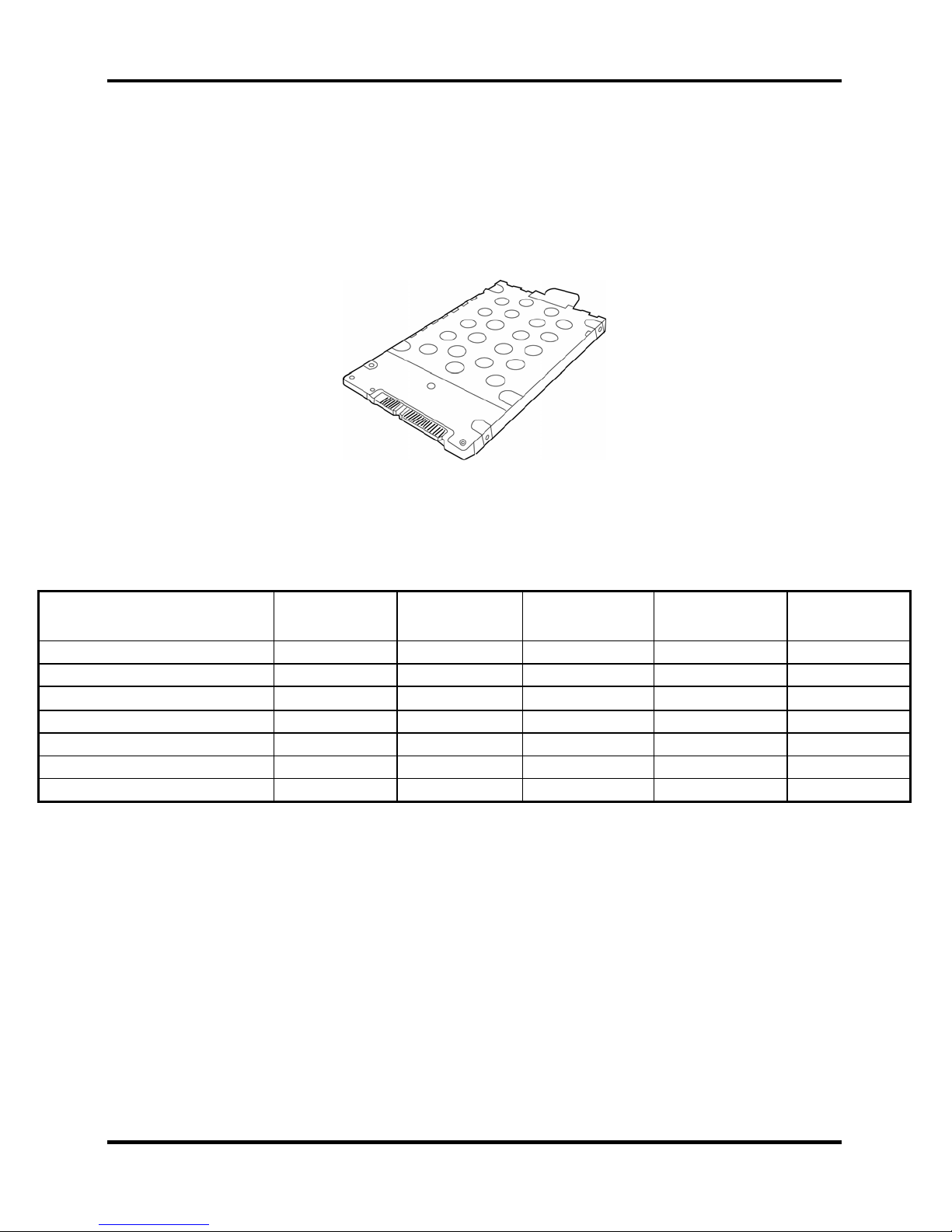
1.3 2.5-inch Hard Disk Drive
The internal HDD is a random access non-volatile storage device. It has a non-removable 2.5inch magnetic disk and mini-Winchester type magnetic heads. The computer supports hard drives
up to 120 GB.
The HDD is shown in Figure 1-1. Specifications are listed in Table 1-1.
Figure 1-1 2.5-inch HDD
Items 40GB 60GB 80GB 100GB 120GB
Formatted capacity (GB) 37.26 55.89 74.52 93.15 111.79
Logical Blocks (LBA) 78,125,000 117,187,500 156,301,488 195,371,568 234,441,648
Rotational speed (rpm) 5400 5400 5400 5400 5400
Toshiba HDD Buffer (MB) 16 16 16 16 16
Hitachi HDD Buffer (MB) 8 8 8 8 None
Fujitsu HDD Buffer (MB) 8 8 8 8 8
Bytes per sector 512 512 512 512 512
Table 1-1 2.5-inch HDD specifications
1-8
[CONFIDENTIAL]
Detroit 20 /Detroit 20E Series Maintenance Manual
1.4 Optical Device Drives 1 Hardware Overview
1.4 Optical Device Drives
• DVD-ROM & CD-RW drive
• DVD Super Multi drive supporting ±R Double Layer
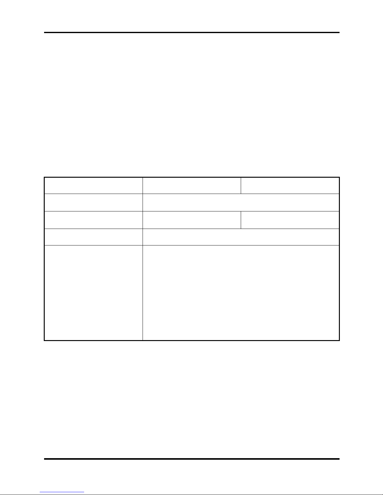
1.4.1 DVD-ROM & CD-RW
The DVD-ROM and CD-RW drive accepts 12-cm (4.72-inch) and 8-cm (3.15-inch) discs. At
maximum, the drive can play back a DVD at 8x speed, read CD-ROM at 24x speed, and write
CD-R at 24x speed and Multi speed CD-RW at 4x speed or High speed CD-RW at 10x or Ultra
speed CD-RW at 24X speed.
The specifications of the DVD-ROM & CD-RW drive are listed in Table 1-2.
Item DVD-ROM mode CD-ROM mode
Data transfer rate (Mbytes/s)
Access time (ms)
Average random access
33.3 (U-DMA transfer mode 2)
16.6 (PIO mode 4, Multiword DMA mode 2)
180 150
Data buffer size (Mbytes) 2MB
DVD:
DVD-VIDEO, DVD-ROM, DVD-R (3.9G, 4.7G), DVD-RW
(Ver.1.1), DVD-RAM, DVD+R, DVD+RW, DVD+R DL,
DVD-R DL.
Formats supported
CD:
CD-DA, CD-ROM Mode1, Mode2, , CD-R, CD-RW, CDROMXA Mode2 (Form1, Form2), Photo CD (single/multisession), Enhanced CD (CD-EXTRA), CD-Text
Table 1-2 DVD-ROM & CD-RW drive specifications
Detroit 20 /Detroit 20E Series Maintenance Manual
[CONFIDENTIAL]
1-9
1 Hardware Overview 1.4 Optical Device Drives
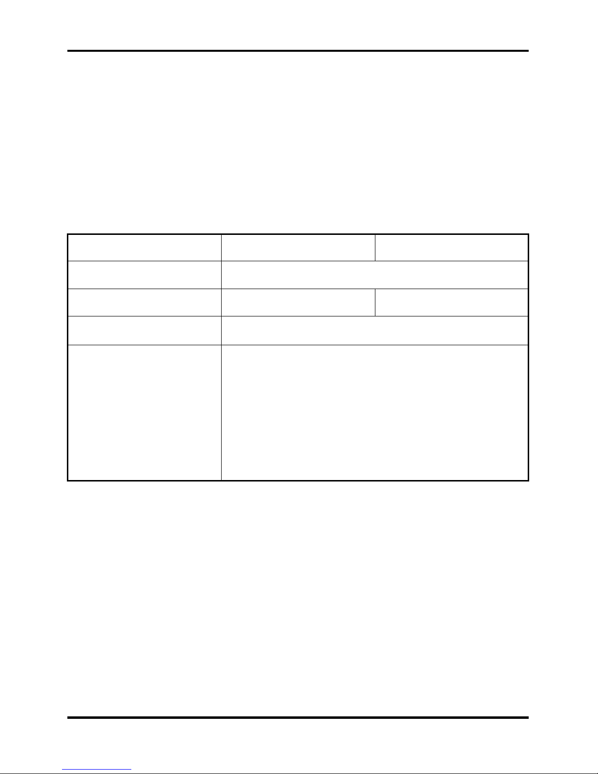
1.4.2 DVD Super Multi drive supporting ±R Double Layer
The DVD Super Multi drive accepts 12-cm (4.72-inch) and 8-cm (3.15-inch) discs. At maximum,
the drive can play back a DVD at 8x speed, read CD-ROM at 24x speed, write CD-R at 24x
speed, Multi speed CD-RW at 4x speed or High speed CD-RW at 10x speed or Ultra speed CDRW at 16x speed, DVD-R at 8x speed, DVD-RW at 4x speed, DVD+R at 8x speed, DVD+RW at
4x speed, DVD-RAM at 5x speed, DVD+R DL at 2.4x speed, and DVD-R DL at 2x speed.
The specifications of the DVD Super Multi Double Layer drive are listed in Table 1-3.
Item DVD-ROM mode CD-ROM mode
Data transfer rate (Mbytes/s)
Access time (ms)
Average random access
33.3 (U-DMA transfer mode 2)
16.6 (PIO mode 4, Multiword DMA mode 2)
180 150
Data buffer size (Mbytes) 2MB
DVD:
DVD-VIDEO, DVD-ROM, DVD-R (3.9G, 4.7G), DVD-RW
(Ver.1.1), DVD-RAM, DVD+R, DVD+RW, DVD+R DL,
Formats supported
DVD-R DL
CD:
CD-DA, CD-ROM, CD-R, CD-RW, CD-ROMXA,
PhotoCD (muitiSession), Video CD, CD-Extra (CD+), CD-Text
Table 1-3 DVD Super Multi Double Layer drive specifications
1-10
[CONFIDENTIAL]
Detroit 20 /Detroit 20E Series Maintenance Manual

1.5 Power Supply 1 Hardware Overview
1.5 Power Supply
This specification defines the performance and characteristic of 65W AC adapter power supply.
It supplies a constant voltage 19V output source for Detroit 20 series notebook computer.
A/D conversion
• The EC uses 10-bit sampling for A/D conversion to determine the following values:
– Battery and temperature
AC adaptor and battery check
• The EC checks the following by A/D converted values:
– Battery installed
• The EC checks the following by GPIO values:
– AC adaptor connected
Abnormal check
• The EC determines whether the condition is abnormal, and if so, stores an error
code into the error register.
Input port management
• The EC monitors the following input signal status:
– System power ON/OFF status
– Direct CD power ON/OFF status
Beep and LED control
• Beep is caused by the low battery status.
• The EC controls the following two kinds of LED
– DC IN LED (one color: green)
• Green = indicates AC adaptor is connected
– Battery LED (two colors: orange and green)
• Green solid = The battery is fully charged.
• Orange = The computer is quick-charging the battery / The battery is low.
Power ON/OFF sequence
• When power is turned on or off, the EC starts the power on or off sequence.
– SQ0-4 = power ON sequence
– SQ5-B = power OFF sequence
Detroit 20 /Detroit 20E Series Maintenance Manual
[CONFIDENTIAL]
1-11

1 Hardware Overview 1.5 Power Supply
Battery charging control
• The EC controls the following.
– The quick charging ON/OFF
– The detection of full charge
Detection of the low battery
• The EC detects the low battery point by the gas gauge.
– LB10M = The system will be driven by the battery for 12 more minutes.
– LB0 = The battery won't be able to drive the system after 3 minutes.
– LB1 = The battery can drive the system only during the suspend process.
– LB2 = The battery cannot drive the system.
New battery installation
• When a new battery is installed, the EC communicates with the E2PROM in the
battery to read information of the newly installed battery.
Battery capacity calculation
• The EC reads battery remaining and percentage capacity from the battery through
SMBus.
1-12
[CONFIDENTIAL]
Detroit 20 /Detroit 20E Series Maintenance Manual
1.6 Batteries 1 Hardware Overview
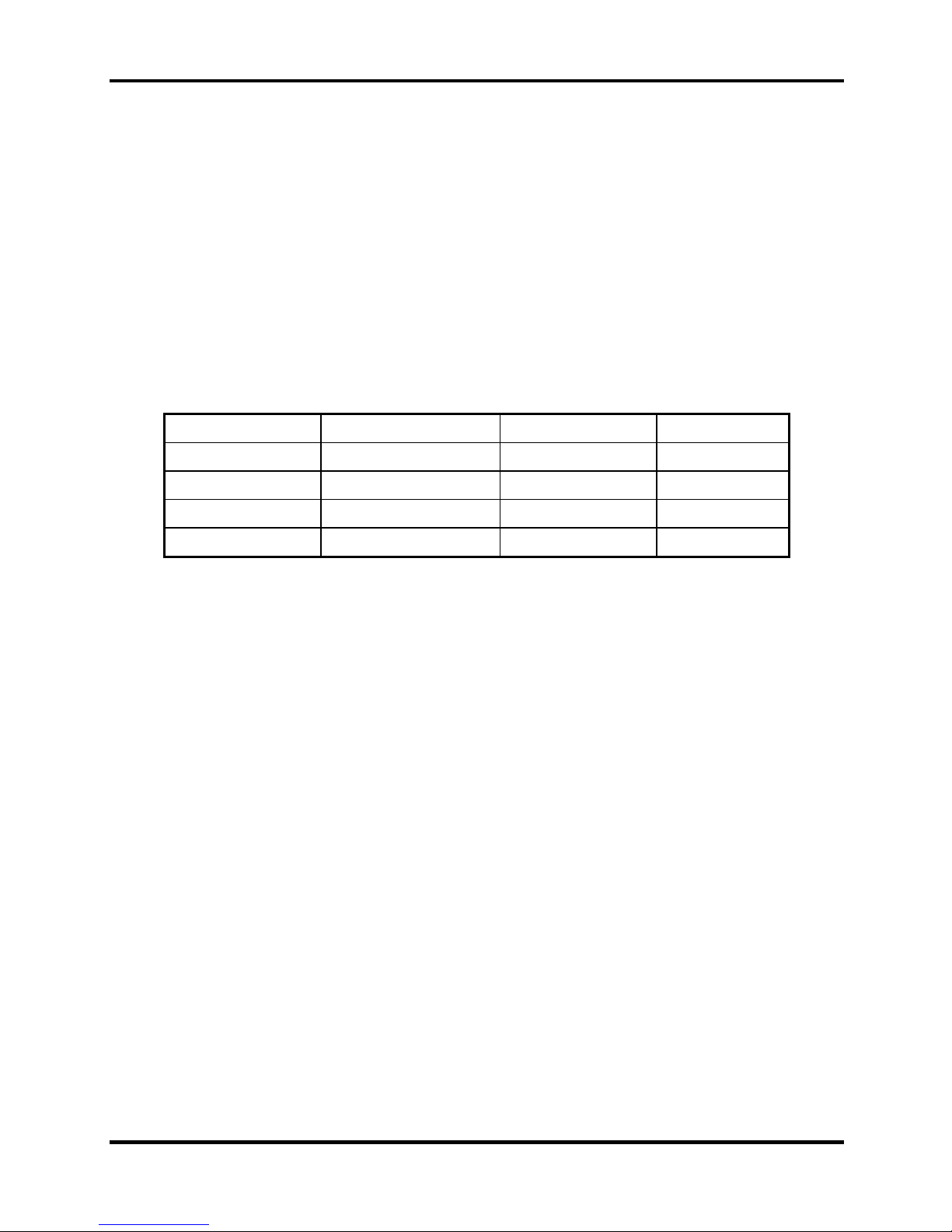
1.6 Batteries
The computer has two types of battery:
Main battery pack (18650 size)
RTC battery
The removable main battery pack is the computer’s main power source when the AC adaptor is
not attached.
The battery specifications are listed in the table below.
Battery name Material Output voltage Capacity
Main battery Lithium-Ion 14.4V(8cell) 4300mAH
Main battery Lithium-Ion 10.8V(6cell) 4000mAH
Main battery * Lithium-Ion 14.4V(4cell) 2000mAH
RTC battery Lithium-Ion 3.0 V 15mAH
* The available of this battery is dependent on the model you purchased.
Detroit 20 /Detroit 20E Series Maintenance Manual
[CONFIDENTIAL]
1-13

1 Hardware Overview 1.6 Batteries
1.6.1 Main Battery
Battery charging is controlled by a power supply microprocessor that is mounted on the system
board. The power supply microprocessor controls whether the charge is on or off and detects a
full charge when the AC adaptor and battery are attached to the computer. The system charges
the battery using quick charge or trickle charge.
Quick battery charge
When the AC adaptor is attached, there are two types of quick charge: quick charge when
the system is powered off and normal charge when the system is powered on.
The times required for charges are listed in the table below.
Status Charging time
Normal charge (power on) 12 hours or longer
Quick charge (power off) About 4 hours or longer
NOTES
1. The time required for normal charge is affected by the amount of power the system
is consuming. Use of the fluorescent lamp and frequent disk access diverts power
and lengthens the charge time.
2. Using quick charge, the power supply microprocessor automatically stops the charge
after eight hours regardless of the condition of the battery. Overcharging could
cause the battery to explode.
If any of the following occurs, the battery quick charge process stops.
1. The battery becomes fully charged.
2. The AC adaptor or battery is removed.
3. The battery or output voltage is abnormal.
4. The battery temperature is abnormal.
5. The battery SMBus communication fails.
6. The battery cell is bad.
Detection of full charge
A full charge is detected from the battery pack through SMBus when the battery is
charging.
1-14
[CONFIDENTIAL]
Detroit 20 /Detroit 20E Series Maintenance Manual
1.6 Batteries 1 Hardware Overview
1.6.2 RTC battery
The RTC battery provides power to keep the current date, time and other setup information in
memory while the computer is turned off. The table below lists the charging time and data
preservation period of the RTC battery. The RTC battery is charged by the adaptor or main
battery, while the computer is powered on.
Status Time
Charging Time (power on) About 24 hours
Data preservation period (full charge) 1 month
Detroit 20 /Detroit 20E Series Maintenance Manual
[CONFIDENTIAL]
1-15

Chapter 2
Troubleshooting Procedures
2
 Loading...