

Toshiba Satellite P775, Satellite P770 Series Series Manual

Toshiba Personal Computer
Satellite P770/P775 Series
Maintenance Manual
TOSHIBA CORPORATION
[CONFIDENTIAL]

Copyright
© 2011 by Toshiba Corporation. All rights reserved. Under the copyright laws, this manual
cannot be reproduced in any form without the prior written permission of Toshiba. No patent
liability is assumed with respect to the use of the information contained herein.
Toshiba Personal Computer Satellite P770/P775 Series Maintenance Manual
First edition March. 2011
Disclaimer
The information presented in this manual has been reviewed and validated for accuracy. The
included set of instructions and descriptions are accurate for the Satellite Series at the time of this
manual's production. However, succeeding computers and manuals are subject to change without
notice. Therefore, Toshiba assumes no liability for damages incurred directly or indirectly from
errors, omissions, or discrepancies between any succeeding product and this manual.
Trademarks
IBM is a registered trademark, and OS/2 and PS/2 are trademarks of IBM Corporation.
Microsoft, MS-DOS, Windows, DirectSound and DirectMusic are registered trademarks of
Microsoft Corporation.
Intel and Pentium are registered trademarks, and SpeedStep is a trademark of Intel Corporation.
Sound Blaster is a registered trademark of Creative Technology Ltd.
Centronics is a registered trademark of Centronics Data Computer Corporation.
Photo CD is a trademark of Eastman Kodak.
All other properties are trademarks or registered trademarks of their respective holders.
Satellite P770/P775 Series Maintenance Manual
[CONFIDENTIAL]
ii
Preface
This maintenance manual describes how to perform hardware service maintenance for the Toshiba
Personal Computer Satellite, referred to as the Satellite Series in this manual.
The procedures described in this manual are intended to help service technicians isolate faulty
Field Replaceable Units (FRUs) and replace them in the field.
SAFETY PRECAUTIONS
Four types of messages are used in this manual to bring important information to your attention.
Each of these messages will be italicized and identified as shown below.
DANGER: “Danger” indicates the existence of a hazard that could result in death or
serious bodily injury if the safety instruction is not observed.
WARNING: “Warning” indicates the existence of a hazard that could result in bodily
injury if the safety instruction is not observed.
CAUTION: “Caution” indicates the existence of a hazard that could result in property
damage if the safety instruction is not observed.
NOTE: “Note” contains general information that relates to your safe maintenance
service.
Improper repair of the computer may result in safety hazards. Toshiba requires service technicians
and authorized dealers or service providers to ensure the following safety precautions are adhered
to strictly.
Be sure to fasten screws securely with the right screwdriver. If a screw is not fully fastened, it
could come loose, creating a danger of a short circuit, which could cause overheating,
smoke or fire.
If you replace the battery pack or RTC battery, be sure to use only the same model battery or
an equivalent battery recommended by Toshiba. Installation of the wrong battery can
cause the battery to explode.
Satellite P770/P775 Series Maintenance Manual
[CONFIDENTIAL]
iii

The manual is divided into the following parts:
Chapter 1 Hardware Overview describes the Satellite Series system unit and each
FRU.
Chapter 2 Troubleshooting Procedures explains how to diagnose and resolve FRU
problems.
Chapter 3 Test and Diagnostics describes how to perform test and diagnostic
operations for maintenance service.
Chapter 4 Replacement Procedures describes the removal and replacement of the
FRUs.
Appendices The appendices describe the following:
Handling the LCD module
Board layout
Pin assignments
Keyboard scan/character codes
Key layout
Screw torque list
Reliability
Conventions
This manual uses the following formats to describe, identify, and highlight terms and operating
procedures.
Acronyms
On the first appearance and whenever necessary for clarification, acronyms are enclosed in
parentheses following their definition. For example:
Read Only Memory (ROM)
Keys
Keys are used in the text to describe many operations. The key top symbol as it appears on the
keyboard is printed in boldface type.
Key operation
Satellite P770/P775 Series Maintenance Manual
[CONFIDENTIAL]
iv

Some operations require you to simultaneously use two or more keys. We identify such operations
by the key top symbols separated by a plus (+) sign. For example, Ctrl + Pause (Break) means
you must hold down Ctrl and at the same time press Pause (Break). If three keys are used, hold
down the first two and at the same time press the third.
User input
Text that you are instructed to type in is shown in the boldface type below:
DISKCOPY A: B:
The display
Text generated by the computer that appears on its display is presented in the typeface below:
Format complete
System transferred
Satellite P770/P775 Series Maintenance Manual
[CONFIDENTIAL]
v

Table of Contents
Chapter 1 Hardware Overview
1.1 Features ................................................................................................................................ 1
1.2 2.5-inch HDD/SSD .............................................................................................................. 9
1.3 DVD Super Multi Drive (±R Double Layer) ..................................................................... 11
1.4 BD-Rewriter and BD-Combo Drives ................................................................................ 12
1.5 Power Supply ..................................................................................................................... 13
1.6 Batteries ............................................................................................................................. 15
1.6.1 Main Battery........................................................................................................ 15
1.6.2 Battery Charging Control .................................................................................... 15
1.6.3 RTC Battery ........................................................................................................ 16
Chapter 2 Troubleshooting Procedures
2.1 Troubleshooting Introduction ............................................................................................ 3
2.2 Troubleshooting Flowchart ……………………………………………………………4
2.3 Power Supply Troubleshooting ……………………………………………………….9
2.4 Display Troubleshooting ................................................................................................... 14
2.5 Keyboard Troubleshooting ............................................................................................... 17
2.6 External USB Devices Troubleshooting ............................................................................ 19
2.7 TV-tuner Troubleshooting ................................................................................................. 21
2.8 TouchPad Troubleshooting ................................................................................................ 23
2.9 Speaker Troubleshooting ................................................................................................... 25
2.10 Optical drive troubleshooting ............................................................................................ 27
2.11 Wireless LAN Troubleshooting ......................................................................................... 30
2.12 Camera Troubleshooting…………………………………………… ……………….32
2.13 Bluetooth Troubleshooting…………………...…………………………….……….. 34
2.14 Bridge Media slot Troubleshooting……………………………………………..……36
2.15 HDD/SSD Troubleshooting……………………………………………..……………38
Satellite P770/P775 Series Maintenance Manual
[CONFIDENTIAL]
vi

2.16 CRT failure Troubleshooting ……………………………………………………….. 40
2.17 HDMI CEC Troubleshooting ………………………………………………………...42
2.18 MIC Troubleshooting ………………………………………………………………. 44
2.19 USB3.0 Troubleshooting …………………………………...………..…………….46
2.20 3D sensor troubleshooting process …………………………………………………..48
2.21 Sleep & charge Troubleshooting……………………………………………………..50
2.22 CIR Troubleshooting…………………………………………………………………52
2.23 Sleep & Play music Troubleshooting……………………………………………...…54
2.24 Wimax Troubleshooting………………………………………………………………56
2.25 LAN Troubleshooting………………………………………………...………………58
2.26 JET Troubleshooting……………………………………………………………...…..60
2.27 Ambient Light sensor Troubleshooting ……………….…………...………………62
2.28 Battery Troubleshooting………………………………………………..………...…..64
2.29 LED Troubleshooting ……………….……………………...……...………………66
Figures
Figure 2-1 Troubleshooting flowchart (2/1) ………………………………………………5
Figure 2-1 Troubleshooting flowchart (2/2) ………………………………………………6
Figure2-2 Power Supply Troubleshooting Process …………………………………..…..9
Figure 2-3 Display troubleshooting process ……………………………………………..14
Figure 2-4 Keyboard troubleshooting process ...................................................................17
Figure 2-5 External USB device troubleshooting process .................................................19
Figure 2-6 TV-tuner troubleshooting process ...................................................................21
Figure 2-7 TouchPad troubleshooting process ..................................................................23
Figure 2-8 Speaker troubleshooting process .....................................................................25
Figure 2-9 Optical drive troubleshooting process .............................................................27
Figure 2-10 Wireless LAN troubleshooting process…………………………………...…30
Figure 2-11 Camera Troubleshooting process…………………………………………….32
Figure 2-12 Bluetooth troubleshooting process ....……………………………….……….34
Figure 2-13 5 in 1 card troubleshooting process……………………………..…….………36
Figure 2-14 HDD troubleshooting process……………………………….………………..38
Figure 2-15 CRT failure troubleshooting process ………………………………………...40
Figure 2-16 HDMI CEC troubleshooting process ………………………………………...42
Satellite P770/P775 Series Maintenance Manual
[CONFIDENTIAL]
vii

Figure 2-17 MIC troubleshooting process ………………………………………………...44
Figure 2-18 USB3.0 Troubleshooting process………………………….………………....46
Figure 2-19 3D sensor troubleshooting process ………………..…………………………48
Figure 2-20 Sleep & Charge Troubleshooting…………….………….……….…..…...….50
Figure 2-21 CIR troubleshooting process …………….………...…………………………52
Figure 2-22 Sleep and Play music troubleshooting process ………………………………54
Figure 2-23 Wimax Troubleshooting process.…………….………….……….…..…...….56
Figure 2-24 LAN troubleshooting process …………………….…………………………..58
Figure 2-25 JET Troubleshooting process………………….………….……….…..…....…60
Figure 2-26 Ambient Light Sensor troubleshooting process………………………….........62
Figure 2-27 Battery troubleshooting process………………….………….………...…....…64
Figure 2-28 LED troubleshooting process…………………………………………….........66
Chapter 3 Tests and Diagnostics
3.1 The Diagnostic Test ............................................................................................................... 2
3.2 Executing the Diagnostic Test ............................................................................................... 3
3.3 Display Configuration ........................................................................................................... 6
3.4 Audio sound Test ................................................................................................................... 7
3.5 Fan ON/OFF Test ................................................................................................................ 10
3.6 Main Battery Charge Test .................................................................................................... 12
3.7 FDD Test .............................................................................................................................. 14
3.8 Memory Check .................................................................................................................... 15
3.9 Keyboard Test ...................................................................................................................... 18
3.10 Mouse (Pad) Test ................................................................................................................. 20
3.11 LCD Pixels Mode Test ........................................................................................................ 21
3.12 Magnetic switch Test ........................................................................................................... 22
3.13 LAN Test ............................................................................................................................. 23
3.14 RTC Test .............................................................................................................................. 25
3.15 BUTTON Test……..…………...………….…….……………..………...……...............26
3.16 1st HDDTest ……………………………....…………….……….…....….………..........28
3.17 2nd HDDTest………………………………………………………………………………30
Satellite P770/P775 Series Maintenance Manual
[CONFIDENTIAL]
viii

3.18 RDMI Test………………...………………………….……………………..…….….......32
3.19 WDMI Test …………….…………………………….…………….…....…..….…….....33
3.20 G Sensor Test ……………………………………………………………….……….........35
3.21 TP TYPE R/W Test………………………………………………….…….……..…..…...39
3.22 EEPROM Setting ………………………..………………………..……….………..…...42
3.23 TOSHIBA LOGO Setting………………………………………………………….....…...46
3.24 DYNABOOK LOGO Setting...........................................................................................48
3.25 LED Test..........................................................................................................................50
Chapter 4 Replacement Procedures
4.1 General ................................................................................................................................ 1
Safety Precautions ............................................................................................................... 2
Before You Begin ................................................................................................................ 4
Disassembly Procedures ...................................................................................................... 5
Assembly Procedures .......................................................................................................... 5
Tools and Equipment .......................................................................................................... 6
Screw Tightening Torque .................................................................................................... 6
Colors of Screw Shanks ...................................................................................................... 7
Symbols of Screws on the Laptop Body ............................................................................. 7
Symbol examples ................................................................................................................ 7
4.2 Battery ................................................................................................................................. 8
Removing the Battery Pack ................................................................................................. 8
Installing the Battery Pack .................................................................................................. 9
4.3 HDD .................................................................................................................................. 10
Removing the HDD ........................................................................................................... 10
Installing the HDD ............................................................................................................ 12
4.4 2nd HDD (Depending on the model) ................................................................................ 15
Removing the 2nd HDD .................................................................................................... 15
Installing the 2nd HDD ..................................................................................................... 16
Satellite P770/P775 Series Maintenance Manual
[CONFIDENTIAL]
ix

4.5 Memory .............................................................................................................................. 17
Removing the Optional Memory ....................................................................................... 17
Installing the Optional Memory ......................................................................................... 18
4.6 ODD ................................................................................................................................... 19
Removing the ODD ............................................................................................................ 19
Installing the ODD ............................................................................................................. 19
Disassembling the ODD ..................................................................................................... 20
Assembling the ODD Drive ............................................................................................... 20
4.7 TV Card ............................................................................................................................. 21
Removing the TV Card ...................................................................................................... 21
Installing the TV Card ........................................................................................................ 21
4.8 Keyboard ............................................................................................................................ 22
Removing the Keyboard .................................................................................................... 22
Installing the Keyboard ...................................................................................................... 24
4.9 WLAN Card ....................................................................................................................... 25
Removing the WLAN Card................................................................................................ 25
Installing the WLAN Card ................................................................................................. 26
4.10 Logic Upper Assembly ...................................................................................................... 27
Removing the Logic Upper Assembly ............................................................................... 27
Installing the Logic Upper Assembly ................................................................................ 29
4.11 Speakers ............................................................................................................................. 30
Removing the Speakers ...................................................................................................... 30
Installing the Speakers ....................................................................................................... 30
4.12 Touchpad on/off & Light bar ............................................................................................. 31
Removing the Touchpad on/off & Light bar ...................................................................... 31
Installing the Touchpad on/off & Light bar ....................................................................... 31
4.13 Touchpad Button Board 32
Removing the Touchpad Button Board .............................................................................. 32
Installing the Touchpad Button Board ............................................................................... 32
4.14 ODD Board ........................................................................................................................ 33
Removing the ODD Board ................................................................................................. 33
Installing the ODD switch board ....................................................................................... 33
Satellite P770/P775 Series Maintenance Manual
[CONFIDENTIAL]
x

4.15 Thermal Fan ...................................................................................................................... 34
Removing the Thermal Fan ............................................................................................... 34
Installing the Thermal Fan ................................................................................................ 34
4.16 USB Board ........................................................................................................................ 35
Removing the Right USB Board on the Right Side .......................................................... 35
Installing the Right USB Board ........................................................................................ 35
4.17 Indicator Board ................................................................................................................. 36
Removing the Indicator Board .......................................................................................... 36
Installing the Indicator Board ............................................................................................ 36
4.18 Logo Board ....................................................................................................................... 37
Removing the Logo Board ................................................................................................ 37
Installing the Logo Board .................................................................................................. 37
4.19 Motherboard ...................................................................................................................... 38
Removing the Motherboard .............................................................................................. 38
Installing the Motherboard ................................................................................................ 38
4.20 CPU and Thermal Module ................................................................................................ 40
Removing the CPU and Thermal Module ......................................................................... 40
Installing the CPU and Thermal Module .......................................................................... 42
4.21 Display Assembly ............................................................................................................. 44
Removing the Display Assembly ...................................................................................... 44
Installing the Display Assembly ....................................................................................... 45
4.22 LCD Bezel ........................................................................................................................ 46
Removing the LCD Bezel ................................................................................................. 46
Installing the LCD Bezel Assembly .................................................................................. 47
4.23 LCD Module ..................................................................................................................... 48
Removing the LCD Module .............................................................................................. 48
Installing the LCD Module ............................................................................................... 51
4.24 Camera Module ................................................................................................................. 52
Removing the Camera Module ......................................................................................... 52
Installing the Camera Module ........................................................................................... 52
4.25 Antennas ........................................................................................................................... 53
Removing the Antennas .................................................................................................... 53
Satellite P770/P775 Series Maintenance Manual
[CONFIDENTIAL]
xi

Installing the Antennas ....................................................................................................... 53
Satellite P770/P775 Series Maintenance Manual
[CONFIDENTIAL]
xii

Figures
Figure 4.1 Removing the Battery Pack ......................................................................................8
Figure 4.2 Removing the logic lower door ..............................................................................10
Figure 4.3 Removing the HDD from the HDD bay .................................................................11
Figure 4.4 Removing the HDD aluminum ...............................................................................12
Figure 4.5 Installing the HDD aluminum foil ..........................................................................13
Figure 4.6 Installing the logic lower door................................................................................14
Figure 4.7 Removing the screw securing the 2nd HDD door ..................................................15
Figure 4.8 Removing the 2nd HDD .........................................................................................16
Figure 4.9 Removing the RAM from the connectors ..............................................................17
Figure 4.10 Removing the ODD ..............................................................................................19
Figure 4.11 Removing the ODD bracket from the ODD .........................................................20
Figure 4.12 Removing the TV card .........................................................................................21
Figure 4.13 Removing screws securing the keyboard .............................................................22
Figure 4.14 Prying up the keyboard .........................................................................................23
Figure 4.15 Disconnecting the FPC and removing the keyboard ............................................23
Figure 4.16 Removing the WLAN Card ..................................................................................25
Figure 4.17 Removing screws from the bottom of the laptop .................................................27
Figure 4.18 Removing three screws ........................................................................................28
Figure 4.19 Disconnecting touchpad FFC and speaker cable from the motherboard ..............28
Figure 4.20 Removing the logic upper assembly from the laptop ...........................................29
Figure 4.21 Removing the speakers .........................................................................................30
Figure 4.22 Removing the touchpad on/off & light bar ..........................................................31
Figure 4.23 Removing the touchpad button board ..................................................................32
Figure 4.24 Disconnecting the ODD board FFC .....................................................................33
Figure 4.25 Removing the thermal fan from the logic lower assembly ...................................34
Figure 4.26 Disconnecting the FFC from the motherboard .....................................................35
Figure 4.27 Disconnecting the FFC from the motherboard .....................................................36
Figure 4.28 Disconnecting the logo board FFC from the motherboard ...................................37
Figure 4.29 Removing the motherboard from the logic lower assembly ................................38
Figure 4.30 Removing the Thermal Module spring screws .....................................................41
Satellite P770/P775 Series Maintenance Manual
[CONFIDENTIAL]
xiii

Figure 4.31 Removing the CPU ............................................................................................... 42
Figure 4.32 Reapply the Shinetsu 7762 grease on the thermal module ................................... 43
Figure 4.33 Removing the screws ............................................................................................ 44
Figure 4.34 Removing the LCD Bezel .................................................................................... 46
Figure 4.35 Removing the LCD Module from the LCD cover assembly ................................ 48
Figure 4.36 Disconnect the camera module cable ................................................................... 49
Figure 4.37 Removing the LCD hinges ................................................................................... 49
Figure 4.38 Removing the LVDS cable from the LCD panel ................................................. 50
Figure 4.39 Installing the LCD hinges .................................................................................... 51
Figure 4.40 Removing the Camera Module ............................................................................. 52
Figure 4.41 Removing the antennas from the LCD cover assembly ....................................... 53
Appendices
Appendix A Handling the LCD Module .................................................................................... A-1
Appendix B Board Layout ......................................................................................................... B-1
Appendix C Pin Assignments .................................................................................................... C-1
Appendix D Keyboard Scan/Character Codes ........................................................................... D-1
Appendix E Key Layout ............................................................................................................ E-1
Appendix F Series Screw Torque List ....................................................................................... F-1
Appendix G Reliability .............................................................................................................. G-1
Satellite P770/P775 Series Maintenance Manual
[CONFIDENTIAL]
xiv

1 Hardware Overview
Chapter 1
Hardware Overview
Satellite P770/P775 Series Maintenance Manual [CONFIDENTIAL]

1 Hardware Overview
Chapter 1 Contents
1.1 Features .................................................................................................................. 1-1
1.2 2.5-inch HDD/SSD ................................................................................................. 1-9
1.3 DVD Super Multi Drive (±R Double Layer) ....................................................... 1-11
1.4 BD-Rewriter and BD-Combo Drives ................................................................... 1-12
1.5 Power Supply ....................................................................................................... 1-13
1.6 Batteries ................................................................................................................ 1-15
1.6.1 Main Battery ......................................................................................... 1-15
1.6.2 Battery Charging Control ..................................................................... 1-15
1.6.3 RTC Battery .......................................................................................... 1-16
[CONFIDENTIAL] Satellite P770/P775 Series Maintenance Manual

1 Hardware Overview
Figures
Figure 1-1 ID Parts Description Placement Part A .......................................................... 1-5
Figure 1-2 ID Parts Description Placement Part B .......................................................... 1-6
Figure 1-3 SATA HDD/SSD ........................................................................................... 1-9
Figure 1-4 DVD Super Multi Drive .............................................................................. 1-11
Figure 1-5 BD-Rewriter or BD-Combo Drive (depending on the model) .................... 1-12
Tables
Table 1-1
HDD Specifications ....................................................................................... 1-9
Table 1-2 SSD Specifications ...................................................................................... 1-10
Table 1-3 DVD Super Multi Drive Specifications ....................................................... 1-11
Table 1-4 Blu-ray Disc Drive specifications ................................................................ 1-12
Table 1-5 Quick/Normal Charging Time ..................................................................... 1-15
Satellite P770/P775 Series Maintenance Manual [CONFIDENTIAL]


1.1 Features 1 Hardware Overview
1.1 Features
The Toshiba P770/P775 is a full-size PC notebook equipped with a Sandy Bridge processor,
providing high-speed processing capabilities and advanced features. The computer employs a
lithium ion battery that allows it to be battery-operated for long periods of time. The display uses
a 17-inch HD LCD, full HD LCD or full HD 3D LCD panel. Many features can be Built To
Order (BTO) to customize the system for each user.
The computer has the following features:
Processor (BTO)
The computer is equipped with one of the following Intel® processors:
Intel® Sandy Bridge Processor Core i3-2310M
Intel® Sandy Bridge Processor Core i5-2540M
Intel® Sandy Bridge Processor Core i7-2630QM
Memory (BTO)
The computer has two SODIMM slots which come standard with 1GB/2GB/4GB, accepting
BTO for your memory requirements. It can incorporate up to 8 GB of main memory and
supports DDR3 1,333MHz.
Battery Pack
The computer is powered by one rechargeable and removable lithium ion battery pack. The
capacity can be either 6-cell or 12-cell, depending on the model of the computer.
RTC Battery
The internal rechargeable RTC battery backs up the Real Time Clock and calendar.
Hard Disk Drive (HDD) (BTO)
The computer accommodates a 2.5"/9.5mm or 2.5"/7mm HDD with the following storage
capacities:
y 250GB~750GB, S-ATA (5,400rpm or 7,200rpm)
Solid State Drive (SSD)
The computer accommodates a 2.5"/9.5mm SSD with the following storage capacities:
y 64GB and 128GB, S-ATA
Satellite P770/P775 Series Maintenance Manual [CONFIDENTIAL] 1-1

1 Hardware Overview 1.1 Features
ODD (BTO)
y 12.7mm height DVD Super Multi Drive supporting ±R Double Layer
y 12.7mm height DVD Super Multi Drive supporting ±R Double Layer w/ Label flash
y 12.7mm height BD-Combo Drive
y 12.7mm height BD-Rewritable Drive
Display
The LCD display comes with the following:
y 17.3" (16:9) HD+ (1,600×900) LED w/ LVDS Interface
y 17.3" (16:9) FHD (1,920×1,080) LED w/ eDP Interface for 3D
y 17.3" (16:9) FHD (1,920×1,080) LED w/ LVDS Interface
Graphics (BTO)
Mobile Intel® Huron River HM65 Chipset for integrated graphics display
y nVIDIA N12P-GS 1GB (DDR3) w/ Optimus
y nVIDIA N12P-GS 1GB (DDR3) for 3D Vision
y nVIDIA N12P-GS 2GB (DDR3) w/ Optimus
y nVIDIA N12P-GS 2GB (DDR3) for 3D Vision
y nVIDIA N12P-GV-B 1GB (DDR3) w/ Optimus
Keyboard
The computer is equipped with a Toshiba standard keyboard, which has 101/102/106 1.7±
0.25mm full stroke keys emulating with desktop keyboard. It is a Win7-compliant keyboard
with optional Windows keys and application keys.
Pointing Device
The integrated Wide Touch Pad and two control buttons in the palm rest allow control of
the on-screen pointer and support functions such as the scrolling of windows.
External Monitor Port
The computer has an analog VGA port.
1-2 [CONFIDENTIAL] Satellite P770/P775 Series Maintenance Manual

1.1 Features 1 Hardware Overview
Universal Serial Bus (USB) Ports
The computer has three USB 2.0 and one USB 3.0 ports. It is supported to daisy-chain a
maximum of 127 USB devices. The serial data transfer rate is 5 Gbps or 480 Mbps or 12
Mbps and 1.5 Mbps. These ports support PnP installation and hot plugging.
Bridge Media Slot
This slot allows you to insert an SD/SDHC/SDXC or MMC or MS/MS Pro/MS Duo/MS
Pro Duo/MS Micro and xD memory card. It supports high-speed SD and SDHC. UHS-I is
also supported on SDXC. The MS Duo/MS Pro Duo/MS Micro memory card needs a
adaptor. This model does not support CF or SmartMedia cards.
Sound system
The integrated sound system is composed of two internal Harman/Kardon speakers, an
internal microphone (BTO with Internal Camera), and standard Microphone-IN and
Headphone-OUT ports. Dolby® Advanced Audio and Sleep & Play music function are also
integrated in the system.
Internal Camera (BTO)
It supports VGA (0.3M)/1.3M/3D stereo (1.0M×2) webcam. An internal microphone is
BTO with the Internal Camera and includes echo cancellation. The camera is not a rotation
type.
Headphones/Line-out Jack
This jack connects digital speakers or stereo headphones (16 ohm minimum). When
connected to digital speakers or headphones, the internal speaker is automatically disabled.
Microphone/ Line-in Jack
A 3.5mm mini microphone jack enables connection of a three-conductor microphone for
monaural input and also enables the connection of a stereo device for audio input.
HDMI Out Port (BTO)
The HDMI out port can connect with a Type A connector HDMI cable. The HDMI out port
can send SD and HD video/audio signals. HDMI or HDMI-CEC is BTO item.
Satellite P770/P775 Series Maintenance Manual [CONFIDENTIAL] 1-3

1 Hardware Overview 1.1 Features
LAN (BTO)
The computer has built-in support for 10M/100M/1000M Ethernet LAN (10/100/1000
megabits per second, 10/100/1000BASE-T). It employs a Realtek RTL8111E for
10M/100M/1000M LAN or Realtek RTL8105E for 10M/100M (for discrete platform,
Realtek RTL8111E for 10M/100M/1000M or Realtek RTL8105E for 10M/100M is
employed). It is pre-installed as a standard device in some markets.
Wireless LAN (BTO)
The computer is equipped with a Wireless LAN (WLAN) card. This WLAN module may
come with the following types:
Atheros 802.11(b/g)13ch-HB95 MOW-HMC
Atheros 802.11(b/g/n)WB195-HMC w/ BT V3.0+HS
Atheros 802.11(b/g)WB195-HMC w/BT V3.0+HS
Intel 802.11(b/g/n)13ch-CP 1x2 MOW-HMC
Realtek 802.11(b/g/n)13ch-RTL8188CE MOW-HMC
Intel 802.16e b/g/n Kelesey Peak (1x2)
Bluetooth (BTO)
Some computers in this series offer Bluetooth wireless communication function which
eliminates the need for cables between electronic devices such as computers and printers.
When implemented, Bluetooth provides wireless communication in a small space. This
module is Version 3.0 + HS (combo module with WLAN), and supports Toshiba stack &
Microsoft stack.
1-4 [CONFIDENTIAL] Satellite P770/P775 Series Maintenance Manual
1.1 Features 1 Hardware Overview
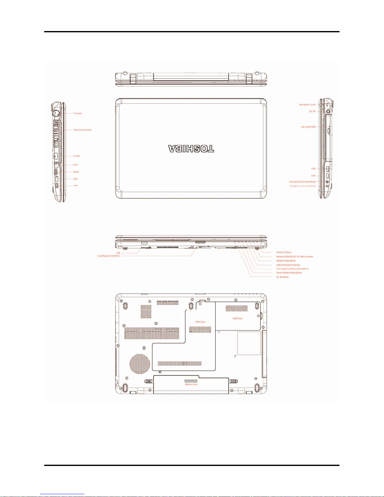
Figure 1-1 and 1-2 show the computer and its system unit configuration.
Figure 1-1 ID Parts Description Placement Part A
Satellite P770/P775 Series Maintenance Manual [CONFIDENTIAL] 1-5
1 Hardware Overview 1.1 Features
Figure 1-2 ID Parts Description Placement Part B
1-6 [CONFIDENTIAL] Satellite P770/P775 Series Maintenance Manual

1.1 Features 1 Hardware Overview
The system unit of the computer consists of the following components:
Processor (BTO)
The computer is equipped with one of the following Intel® processors:
Intel® Sandy Bridge Processor Core i3-2310M
Intel® Sandy Bridge Processor Core i5-2540M
Intel® Sandy Bridge Processor Core i7-2630QM
Memory (BTO)
The computer has two SODIMM slots which come standard with 1GB/2GB/4GB, accepting
BTO for your memory requirements. It can incorporate up to 8 GB of main memory and
supports DDR3 at 1,333MHz.
BIOS ROM (EEPROM)
The system BIOS uses one 4MB/8MB flash ROM. The flash utility can be used to program
both system and keyboard BIOS at the same time.
System Controllers
Advanced Power Management 1.2 support
Support ACPI 3.0B
Support SMBIOS specification V2.4
Hot keys for system control
Audio volume output control
External LED control
Battery scope report and control
Sticky key support
Power switch control
Two host interface channels support
Support three independent devices
Internal Keyboard country selection
Wireless LAN on/off button
Satellite P770/P775 Series Maintenance Manual [CONFIDENTIAL] 1-7

1 Hardware Overview 1.1 Features
Graphics Controller (BTO)
Mobile Intel® Huron River HM65 Chipset for integrated graphics display
y nVIDIA N12P-GS 1GB (DDR3) w/ Optimus
y nVIDIA N12P-GS 1GB (DDR3) for 3D Vision
y nVIDIA N12P-GS 2GB (DDR3) w/ Optimus
y nVIDIA N12P-GS 2GB (DDR3) for 3D Vision
y nVIDIA N12P-GV-B 1GB (DDR3) w/ Optimus
Audio Controller
Realtek Azalia ALC269 for Sleep/Music
One Audio-in port
One Audio-out port: Headphone-out
Internal Microphone (BTO with Internal Camera, MIC with echo cancellation)
Synchronize to change sound output to HDMI
Software EQ support
Dolby support for Harman Kardom
MAXX Audio is supported (JPN only)
Sleep & Play music support
Wireless LAN Controller (BTO)
Atheros 802.11(b/g)13ch-HB95 MOW-HMC
Atheros 802.11(b/g/n)WB195-HMC w/ BT V3.0+HS
Atheros 802.11(b/g)WB195-HMC w/BT V3.0+HS
Intel 802.11(b/g/n)13ch-CP 1x2 MOW-HMC
Realtek 802.11(b/g/n)13ch-RTL8188CE MOW-HMC
Intel 802.16e b/g/n Kelesey Peak (1x2)
1-8 [CONFIDENTIAL] Satellite P770/P775 Series Maintenance Manual
1.2 2.5-inch HDD/SSD 1 Hardware Overview
1.2 2.5-inch HDD/SSD
The computer contains an extremely low-profile and lightweight, high-performance HDD/SSD.
The HDD/SSD incorporates a 9.5 mm or 7 mm (Only for HDD) height. The HDD/SSD interface
conforms to Serial ATA. Storage capacities supported are 250, 320, 500, 640 and 750GB for
HDD, and 64 and 128GB for SSD.
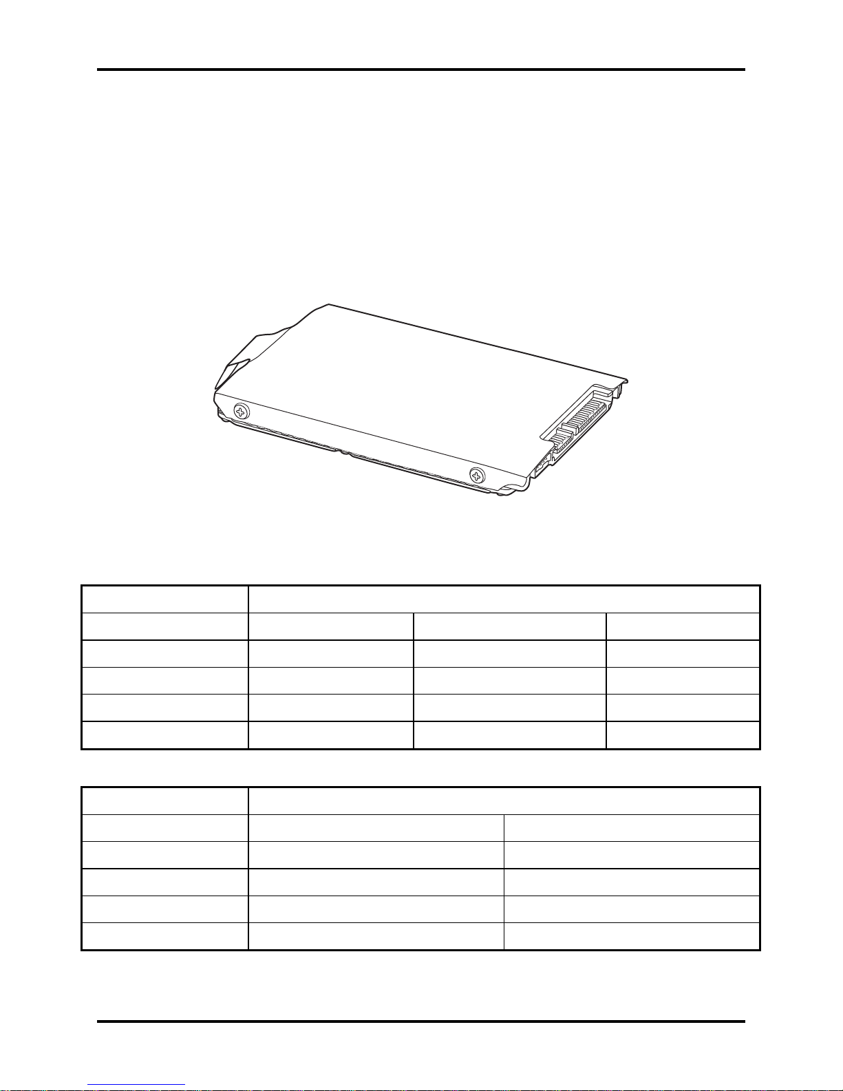
The HDD/SSD is shown in Figure 1-3. Some of HDD specifications are listed in Table 1-1 and
some of SSD specifications are listed in Table 1-2.
Figure 1-3 SATA HDD/SSD
Table 1-1 HDD Specifications
Item
Capacity (GB)
Rotational Speed (RPM)
Height
User Data Sectors
Bytes / Sector 512 512 512 or 4,096
250G 320GB 500G
5,400 RPM 5,400 RPM 5,400 or 7,200 RPM
7 or 9.5 mm 7 or 9.5 mm 9.5 mm
488,397,168 625,142,448 976,773,168
Specifications
Item
Capacity (GB)
Rotational Speed (RPM)
Height
640GB 750GB
5,400 RPM 5,400 or 7,200 RPM
9.5 mm 9.5 mm
Specifications
User Data Sectors
Bytes / Sector 512 or 4,096 4,096
Satellite P770/P775 Series Maintenance Manual [CONFIDENTIAL] 1-9
1,250,263,728 1,465,170,336
1 Hardware Overview 1.2 2.5-inch HDD/SSD
Table 1-2 SSD Specifications
Item
Capacity (GB)
Height
User Data Sectors
Bytes / Sector 512 512
64GB 128GB
9.5 mm 9.5 mm
125,045,424 250,069,680
Specifications
1-10 [CONFIDENTIAL] Satellite P770/P775 Series Maintenance Manual
1.3 DVD Super Multi Drive (±R Double Layer) 1 Hardware Overview
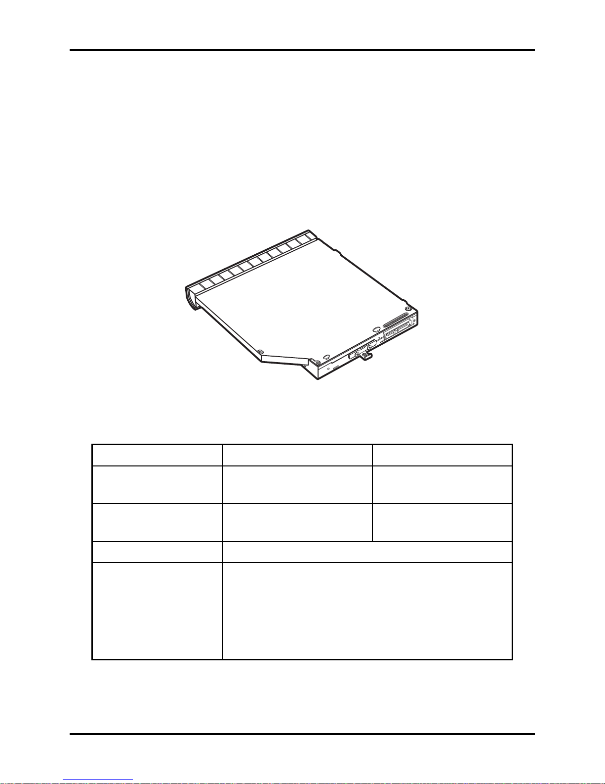
1.3 DVD Super Multi Drive (±R Double Layer)
The DVD Super Multi drive accepts 12-cm (4.72-inch) and 8-cm (3.15-inch) discs. At maximum,
the drive can play back a DVD at 8x speed, read CD-ROM at 24x speed, and write CD-R at 24x
speed, CD-RW at 24x speed, DVD-R at 8x speed, DVD-R (Dual Layer) at 6x speed, DVD-RW
at 6x speed, DVD+R at 8x speed, DVD+R (Double Layer) at 6x speed, DVD+RW at 8x speed
and DVD-RAM at 5x speed.
The DVD Super Multi drive is shown in Figure 1-4 and its specifications are listed in Table 1-3.
Figure 1-4 DVD Super Multi Drive
Table 1-3 DVD Super Multi Drive Specifications
Item DVD-ROM Mode CD-ROM Mode
Data Transfer Rate (Mbytes/s) 10.8MB/s 3.6MB/s
Access Time (ms)
Average Random Access
Data Buffer Size (Mbytes) 2MB
DVD:
DVD-VIDEO, DVD-ROM, DVD-R, DVD-RW, DVD-R (Dual Layer),
DVD+R, DVD+RW, DVD+R (Double Layer), DVD-RAM.
Formats Supported
CD:
CD-DA, CD-ROM, CD-R, CD-RW, CD-ROMXA, Photo CD
(Multi-Session), Video CD, CD-Extra (CD+), CD-Text, SACD, CD-I.
190ms 170ms
Satellite P770/P775 Series Maintenance Manual [CONFIDENTIAL] 1-11
1 Hardware Overview 1.4 BD-Rewriter and BD-Combo Drives
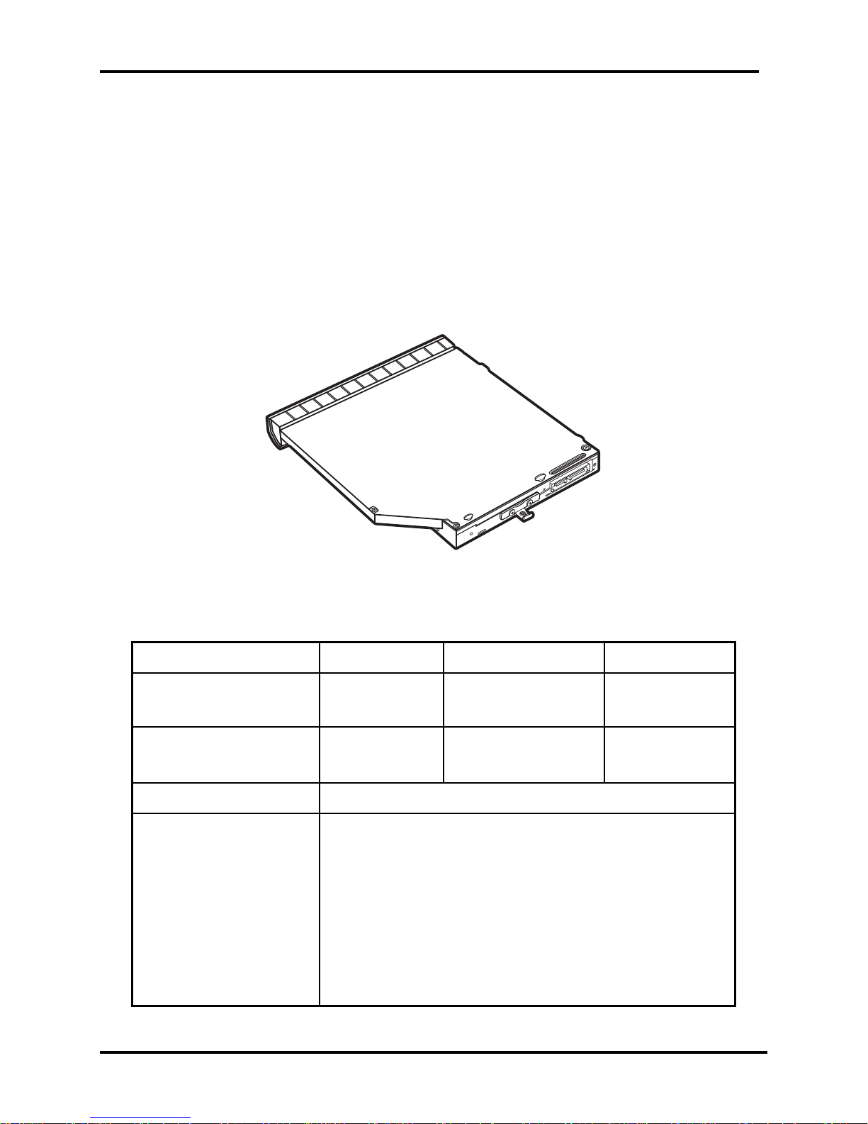
1.4 BD-Rewriter and BD-Combo Drives
The BD-Rewriter and BD-Combo Drives accept 12-cm (4.72-inch) and 8-cm (3.15-inch) discs.
At maximum, the drive can play back a DVD at 8x speed, read CD-ROM at 24x speed, and write
CD-R at 24x speed, CD-RW at 24x speed, DVD-R at 8x speed, DVD-R (Dual Layer) at 4x speed,
DVD-RW at 6x speed, DVD+R at 8x speed, DVD+R (Double Layer) at 4x speed, DVD+RW at
8x speed and DVD-RAM at 5x speed.
The BD-Rewriter or BD-Combo drive is shown in Figure 1-5 and its specifications are listed in
Table 1-4.
Figure 1-5 BD-Rewriter or BD-Combo Drive (depending on the model)
Table 1-4 Blu-ray Disc Drive specifications
Item BD-ROM Mode DVD-ROM Mode CD-ROM Mode
Data Transfer Rate (Mbytes/s) 27MB/s 10.8MB/s 3.6MB/s
Access Time (ms)
Average Random Access
Data Buffer Size (Mbytes) 2MB
Formats Supported
300ms 190ms 180ms
BD:
BD-ROM, BD-R, BD-R (DL), BD-RE, BD-RE (DL)
DVD:
DVD-VIDEO, DVD-ROM, DVD-R, DVD-RW, DVD-RAM, DVD+R,
DVD+R (Double Layer), DVD-R (Dual Layer), DVD+RW.
CD:
1-12 [CONFIDENTIAL] Satellite P770/P775 Series Maintenance Manual
CD-DA, CD-ROM, CD-R, CD-RW, CD-ROMXA, Photo CD
(Multi-Session), Video CD, CD-Extra (CD+), CD-Text, Hybrid SACD.
 Loading...