

Toshiba Satellite P500, Qosmio G60, Qosmio X505, Satellite P500D, Satellite P505D User Manual
...
TOSHIBA
Satellite P500 / Satellite P505
Qosmio X500 / Qosmio G60 /
Qosmio X505
Satellite
P500D / Satellite P505D
Satellite P507
/
Satellite P507D
Portable Personal Computer
User's Manual
Downloaded from LpManual.com Manuals

User’s Manual ii
Copyright
© 2009 by TOSHIBA Corporation. All rights reserved. Under the copyright
laws, this manual cannot be reproduced in any form without the prior
written permission of TOSHIBA. No patent liability is assumed, with respect
to the use of the information contained herein.
TOSHIBA Satellite P500 / Satellite P505 / Satellite P507, Qosmio X505,
Qosmio X500, Qosmio G60, Satellite P500D / Satellite P505D / Satellite
P507D Series
Portable Personal Computer User's Manual
First edition August 2009
Copyright authority for music, movies, computer programs, databases, and
other intellectual property covered by copyright laws belongs to the author
or the copyright owner. Copyrighted material can be reproduced only for
personal use or use within the home. Any other use beyond that stipulated
above (including conversion to digital format, alteration, transfer of copied
material and distribution on a network) without the permission of the
copyright owner is a violation of copyright or author’s rights and is subject
to civil damages or criminal action. Please comply with copyright laws in
making any reproduction from this manual.
Please note that you may infringe the owner's rights protected by the
copyright laws if you use the screen mode switching functions (e.g. Wide
mode, Wide Zoom mode, etc.) of this product to display enlarged images/
video at coffee shops or hotels for the purposes of profits or providing these
to the public.
Disclaimer
This manual has been validated and reviewed for accuracy. The
instructions and descriptions it contains are accurate for the TOSHIBA
Satellite P500 / Satellite P505 / Satellite P507, Qosmio X505, Qosmio
X500, Qosmio G60, Satellite P500D / Satellite P505D / Satellite P507D
Series Portable Personal Computer at the time of this manual’s production.
However, succeeding computers and manuals are subject to change
without notice. TOSHIBA assumes no liability for damages incurred directly
or indirectly from errors, omissions or discrepancies between the computer
and the manual.
This product incorporates copyright protection technology that is protected
by U.S. patents and other intellectual property rights. Use of this copyright
protection technology must be authorized by Macrovision, and is intended
for home and other limited viewing uses only unless otherwise authorized
by Macrovision. Reverse engineering or disassembly is prohibited.
Downloaded from LpManual.com Manuals

User’s Manual iii
Trademarks
IBM is a registered trademark and IBM PC is a trademark of International
Business Machines Corporation.
Windows and Microsoft are registered trademarks of Microsoft Corporation.
DirectX, AcriveDesktop, DirectShow, and Windows Media are registered
trademarks of Microsoft Corporation.
Intel, Intel Core, Celeron, Centrino and Pentium are trademarks or
registered trademarks of Intel Corporation or its subsidiaries in the United
States and other countries.
AMD, the AMD Arrow logo, AMD Athlon, AMD Turion, AMD Sempron, ATI
Radeon, ATI Mobility Radeon and combinations thereof are trademarks of
Advanced Micro Devices, Inc.
Adobe and Photoshop are either registered trademarks or trademarks of
Adobe Systems Incorporated in the United States and/or other countries.
Bluetooth™ is a registered trademark owned by its proprietor and used by
TOSHIBA under license.
ConfigFree is a trademark of TOSHIBA Corporation.
WinDVD is a trademark of Corel Corporations.
DVD MovieFactory is a trademark of Corel Corporations.
Dolby is a registered trademark of Dolby Laboratories.
ExpressCard is a trademark of PCMCIA.
HDMI, the HDMI logo and High-Definition Multimedia Interface are
trademarks or registered trademarks of HDMI Licensing LLC.
Blu-ray Disc is a trademark.
Labelflash(TM) is a trademark of YAMAHA CORPORATION.
Memory Stick, Memory Stick PRO, and i.LINK are registered trademarks
and i.LINK is a trademark of SonyCorporation.
MultiMediaCard and MMC are trademarks of MultiMediaCard Association.
Photo CD is a trademark of Eastman Kodak.
Secure Digital and SD are trademarks of SD Card Association.
xD-Picture Card is a trademark of Fuji Photo Film, Co., Ltd.
WiMAX, WiMAX Forum, WiMAX Certified, WiMAX Forum Certified, the
WiMAX Forum logo and the WiMAX Forum Certified Logo are trademarks
or registered trademarks of the WiMAX Forum.
Wi-Fi is a registered trademark of the Wi-Fi Alliance.
Other trademarks and registered trademarks not listed above may be used
in this manual.
Downloaded from LpManual.com Manuals

User’s Manual iv
FCC information
FCC notice “Declaration of Conformity Information”
This equipment has been tested and found to comply with the limits for a
Class B digital device, pursuant to part 15 of the FCC rules. These limits
are designed to provide reasonable protection against harmful interference
in a residential installation. This equipment generates, uses and can radiate
radio frequency energy and, if not installed and used in accordance with the
instructions, may cause harmful interference to radio communications.
However, there is no guarantee that interference will not occur in a
particular installation. If this equipment does cause harmful interference to
radio or television reception, which can be determined by turning the
equipment off and on, the user is encouraged to try to correct the
interference by one or more of the following measures:
■ Reorient or relocate the receiving antenna.
■ Increase the separation between the equipment and receiver.
■ Connect the equipment into an outlet on a circuit different from that to
which the receiver is connected.
■ Consult the dealer or an experienced radio/TV technician for help.
FCC conditions
This device complies with part 15 of the FCC Rules. Operation is subject to
the following two conditions:
1. This device may not cause harmful interference.
2. This device must accept any interference received, including
interference that may cause undesired operation.
Contact
Only peripherals complying with the FCC class B limits may be attached to
this equipment. Operation with non-compliant peripherals or peripherals
not recommended by TOSHIBA is likely to result in interference to radio
and TV reception. Shielded cables must be used between the external
devices and the computer’s external monitor port, USB port, serial port,
parallel port, PS/2 mouse/keyboard port and microphone jack. Changes or
modifications made to this equipment, not expressly approved by
TOSHIBA or parties authorized by TOSHIBA could void the user’s
authority to operate the equipment.
Address: TOSHIBA America Information Systems, Inc.
9740 Irvine Boulevard
Irvine, California 92618-1697
Telephone: (949) 583-3000
Downloaded from LpManual.com Manuals

User’s Manual v
EU Conformity Statement
This product and - if applicable - the supplied accessories too are marked
with "CE" and comply therefore with the applicable harmonized European
standards listed under the Low Voltage Directive 2006/95/EC, the EMC
Directive 2004/108/EC and/or R&TTE Directive 1999/5/EC.
The complete official EU CE Declaration can be obtained on following
internet page:
http://epps.toshiba-teg.com/
VCCI Class B Information
Important Safety Information for Computers with TV
tuner
IEC60950-1/EN60950-1 Information technology equipment - Safety Coaxial cable connection to this computer must only be used if the cable
outer conductive shielding has been grounded by the cable installer at the
building premises as close to the point of cable entrance, or attachment, as
practicable and the connection complies with all local cable installation
requirements that are applicable in your area.
Responsible for CEmarking:
“TOSHIBA EUROPE GMBH, Hammfelddamm 8,
41460 Neuss, Germany.
Manufacturer: Toshiba Corporation, 1-1 Shibaura 1-chome,
Minato-ku, Tokyo, 105-8001, Japan.
ߎߩⵝ⟎ߪޔࠢࠬ㧮ᖱႎᛛⴚⵝ⟎ߢߔޕߎߩⵝ⟎ߪޔኅᐸⅣႺߢ↪ߔࠆ
ߎߣࠍ⋡⊛ߣߒߡ߹ߔ߇ޔߎߩⵝ⟎߇ࠫࠝ߿࠹ࡆ࡚ࠫࡦฃାᯏߦㄭធߒ
ߡ↪ߐࠇࠆߣޔฃା㓚ኂࠍᒁ߈ߎߔߎߣ߇ࠅ߹ߔޕ
ขᛒ⺑ᦠߦᓥߞߡᱜߒขࠅᛒࠍߒߡߊߛߐޕ
VCCI-B
Downloaded from LpManual.com Manuals

User’s Manual vi
Modem warning notice
Conformity Statement
The equipment has been approved to [Council Decision 98/482/EC - "TBR
21"] for pan-European single terminal connection to the Public Switched
Telephone Network (PSTN).
However, due to differences between the individual PSTNs provided in
different countries/regions the approval does not, of itself, give an
unconditional assurance of successful operation on every PSTN network
termination point.
In the event of problems, you should contact your equipment supplier in the
first instance.
Network Compatibility Statement
This product is designed to work with, and is compatible with the following
networks. It has been tested to and found to conform with the additional
requirements conditional in EG 201 121.
Specific switch settings or software setup are required for each network,
please refer to the relevant sections of the user guide for more details.
The hookflash (timed break register recall) function is subject to separate
national type approvals. It has not been tested for conformity to national
type regulations, and no guarantee of successful operation of that specific
function on specific national networks can be given.
This information is applicable to the models equipped with a built-in
modem.
Germany ATAAB AN005, AN006, AN007, AN009, AN010 and
DE03, 04, 05, 08, 09,12,14,17
Greece ATAAB AN005, AN006 and GR01, 02, 03, 04
Portugal ATAAB AN001, 005, 006, 007, 011 and P03, 04, 08,
10
Spain ATAAB AN005, 007, 012, and ES01
Switzerland ATAAB AN002
All other countries/
regions
ATAAB AN003, 004
Downloaded from LpManual.com Manuals
User’s Manual vii
Japan regulations
Region selection
If you are using the computer in Japan, technical regulations described in
the Telecommunications Business Law require that you select the Japan
region mode. It is illegal to use the modem in Japan with any other
selection.
Redial
Up to two redial attempts can be made. If more than two redial attempts are
made, the modem will return Black Listed. If you are experiencing problems
with the Black Listed code, set the interval between redials at one minute or
longer.
Japan's Telecommunications Business Law permits up to two redials on
analogue telephones, but the redials must be made within a total of three
minutes.
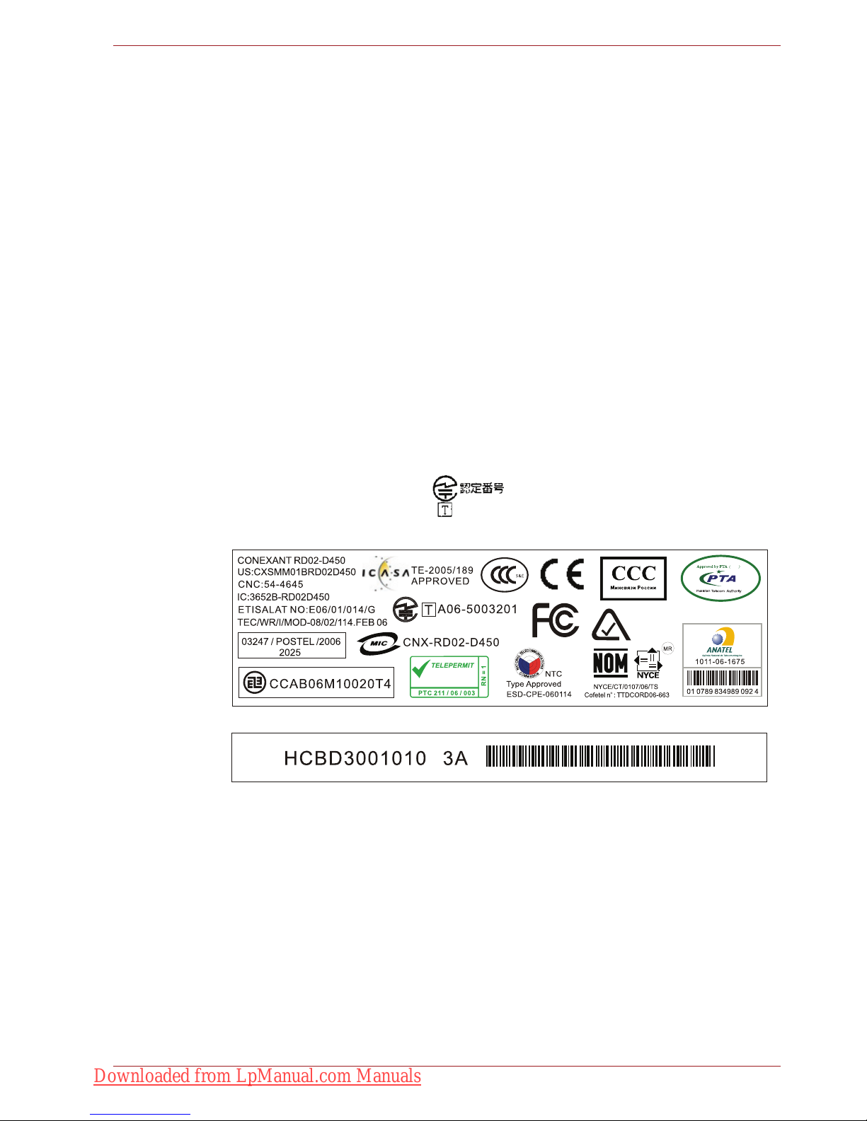
The internal modem is approved by Japan Approvals Institute for
Telecommunications Equipment.
A06-5003201
This Conexant RD02-D450
PSTN Modem may be
connected to the Telecom
Network
2006
N51
Downloaded from LpManual.com Manuals

User’s Manual viii
Pursuant to FCC CFR 47, Part 68:
When you are ready to install or use the modem, call your local telephone
company and give them the following information:
■ The telephone number of the line to which you will connect the modem.
■ The registration number that is located on the device
US : CXSMM01BRD02D450
The FCC registration number of the modem will be found on either the
device which is to be installed, or, if already installed, on the bottom of
the computer outside of the main system label.
■ The Ringer Equivalence Number (REN) of the modem, which can vary.
For the REN of your modem, refer to your modem’s label.
The modem connects to the telephone line by means of a standard jack
called the USOC RJ11C.
Type of service
Your modem is designed to be used on standard-device telephone lines.
Connection to telephone company-provided coin service (central office
implemented systems) is prohibited. Connection to party lines service is
subject to state tariffs.
If you have any questions about your telephone line, such as how many
pieces of equipment you can connect to it, the telephone company will
provide this information upon request.
Telephone company procedures
The goal of the telephone company is to provide you with the best service it
can. In order to do this, it may occasionally be necessary for them to make
changes in their equipment, operations, or procedures. If these changes
might affect your service or the operation of your equipment, the telephone
company will give you notice in writing to allow you to make any changes
necessary to maintain uninterrupted service.
If problems arise
If any of your telephone equipment is not operating properly, you should
immediately remove it from your telephone line, as it may cause harm to
the telephone network. If the telephone company notes a problem, they
may temporarily discontinue service. When practical, they will notify you in
advance of this disconnection. If advance notice is not feasible, you will be
notified as soon as possible. When you are notified, you will be given the
opportunity to correct the problem and informed of your right to file a
complaint with the FCC. In the event repairs are ever needed on your
modem, they should be performed by TOSHIBA Corporation or an
authorized representative of TOSHIBA Corporation.
Disconnection
If you should ever decide to permanently disconnect your modem from its
present line, please call the telephone company and let them know of this
change.
Downloaded from LpManual.com Manuals

User’s Manual ix
Fax branding
The Telephone Consumer Protection Act of 1991 makes it unlawful for any
person to use a computer or other electronic device to send any message
via a telephone fax machine unless such message clearly contains in a
margin at the top or bottom of each transmitted page or on the first page of
the transmission, the date and time it is sent and an identification of the
business, other entity or individual sending the message and the telephone
number of the sending machine or such business, other entity or individual.
In order to program this information into your fax modem, you should
complete the setup of your fax software before sending messages.
Instructions for IC CS-03 certified equipment
1. The Industry Canada label identifies certified equipment. This
certification means that the equipment meets certain
telecommunications network protective, operational and safety
requirements as prescribed in the appropriate Terminal Equipment
Technical Requirements document(s). The Department does not
guarantee the equipment will operate to the user’s satisfaction.
Before installing this equipment, users should ensure that it is
permissible to be connected to the facilities of the local
telecommunications company. The equipment must also be installed
using an acceptable method of connection.
The customer should be aware that compliance with the above
conditions may not prevent degradation of service in some situations.
Repairs to certified equipment should be coordinated by a
representative designated by the supplier. Any repairs or alterations
made by the user to this equipment, or equipment malfunctions, may
give the telecommunications company cause to request the user to
disconnect the equipment.
Users should ensure for their own protection that the electrical ground
connections of the power utility, telephone lines and internal metallic
water pipe system, if present, are connected together. This precaution
may be particularly important in rural areas.
2. The user manual of analog equipment must contain the equipment’s
Ringer Equivalence Number (REN) and an explanation notice similar to
the following:
The Ringer Equivalence Number (REN) of the modem, which can vary.
For the REN of your modem, refer to your modem’s label.
Use only No.26AWG or larger telecommunication line cord.
Users should not attempt to make such connections themselves, but
should contact the appropriate electric inspection authority, or electrician,
as appropriate.
Downloaded from LpManual.com Manuals

User’s Manual x
3. The standard connecting arrangement (telephone jack type) for this
equipment is jack type(s): USOC RJ11C.
The IC registration number of the modem is shown below.
Canada: 3652B-RD02D450
Notes for Users in Australia and New Zealand
Modem warning notice for Australia
Modems connected to the Australian telecoms network must have a valid
Austel permit. This modem has been designed to specifically configure to
ensure compliance with Austel standards when the country/region selection
is set to Australia. The use of other country/region setting while the modem
is attached to the Australian PSTN would result in you modem being
operated in a non-compliant manner. To verify that the country/region is
correctly set, enter the command ATI9 which displays the currently active
setting.
To set the country/region permanently to Australia, enter the following
command sequence:
AT+GCI=09
Failure to set the modem to the Australia country/region setting as shown
above will result in the modem being operated in a non-compliant manner.
Consequently, there would be no permit in force for this equipment and the
Telecoms Act 1991 prescribes a penalty of $12,000 for the connection of
non-permitted equipment.
The Ringer Equivalence Number (REN) assigned to each terminal device
provides an indication of the maximum number of terminals allowed to be
connected to a telephone interface. The termination on an interface may
consist of any combination of devices subject only to the requirement that
the sum of the Ringer Equivalence Numbers of all the devices does not
exceed 5.
Downloaded from LpManual.com Manuals

User’s Manual xi
Notes for use of this device in New Zealand
■ The grant of a Telepermit for a device in no way indicates Telecom
acceptance of responsibility for the correct operation of that device
under all operating conditions. In particular the higher speeds at which
this modem is capable of operating depend on a specific network
implementation which is only one of many ways of delivering high
quality voice telephony to customers. Failure to operate should not be
reported as a fault to Telecom.
■ In addition to satisfactory line conditions a modem can only work
properly if:
a/ it is compatible with the modem at the other end of the call and
b/ the application using the modem is compatible with the application
at the other end of the call - e.g., accessing the Internet requires
suitable software in addition to a modem.
■ This equipment shall not be used in any manner which could constitute
a nuisance to other Telecom customers.
■ Some parameters required for compliance with Telecom’s PTC
Specifications are dependent on the equipment (PC) associated with
this modem. The associated equipment shall be set to operate within
the following limits for compliance with Telecom Specifications:
a/ There shall be no more than 10 call attempts to the same number
within any 30 minute period for any single manual call initiation, and
b/ The equipment shall go on-hook for a period of not less than 30
seconds between the end of one attempt and the beginning of the
next.
c/ Automatic calls to different numbers shall be not less than 5
seconds apart.
■ Immediately disconnect this equipment should it become physically
damaged, and arrange for its disposal or repair.
■ The correct settings for use with this modem in New Zealand are as
follows:
ATB0 (CCITT operation)
AT&G2 (1800 Hz guard tone)
AT&P1 (Decadic dialling make-break ratio = 33%/67%)
ATS0=0 (not auto answer)
ATS10=less than 150 (loss of carrier to hang up delay, factory default of
15 recommended)
ATS11=90 (DTMF dialling on/off duration=90 ms)
ATX2 (Dial tone detect, but not (U.S.A.) call progress detect)
■ When used in the Auto Answer mode, the S0 register must be set with a
value of 3 or 4. This ensures:
■ a person calling your modem will hear a short burst of ringing before
the modem answers. This confirms that the call has been
successfully switched through the network.
■ caller identification information (which occurs between the first and
Downloaded from LpManual.com Manuals

User’s Manual xii
second ring cadences) is not destroyed.
■ The preferred method of dialling is to use DTMF tones (ATDT...) as this
is faster and more reliable than pulse (decadic) dialling. If for some
reason you must use decadic dialling, your communications program
must be set up to record numbers using the following translation table
as this modem does not implement the New Zealand “Reverse dialling”
standard.
Number to be dialled: 0 1 2 3 4 5 6 7 8 9
Number to program into computer: 0 9 8 7 6 5 4 3 2 1
Note that where DTMF dialling is used, the numbers should be entered
normally.
■ The transmit level from this device is set at a fixed level and because of
this there may be circumstances where the performance is less than
optimal. Before reporting such occurrences as faults, please check the
line with a standard Telepermitted telephone, and only report a fault if
the phone performance is impaired.
■ It is recommended that this equipment be disconnected from the
Telecom line during electrical storms.
■ When relocating the equipment, always disconnect the Telecom line
connection before the power connection, and reconnect the power first.
■ This equipment may not be compatible with Telecom Distinctive Alert
cadences and services such as FaxAbility.
NOTE THAT FAULT CALLOUTS CAUSED BY ANY OF THE ABOVE
CAUSES MAY INCUR A CHARGE FROM TELECOM
General conditions
As required by PTC 100, please ensure that this office is advised of any
changes to the specifications of these products which might affect
compliance with the relevant PTC Specifications.
The grant of this Telepermit is specific to the above products with the
marketing description as stated on the Telepermit label artwork. The
Telepermit may not be assigned to other parties or other products without
Telecom approval.
A Telepermit artwork for each device is included from which you may
prepare any number of Telepermit labels subject to the general instructions
on format, size and color on the attached sheet.
The Telepermit label must be displayed on the product at all times as proof
to purchasers and service personnel that the product is able to be
legitimately connected to the Telecom network.
The Telepermit label may also be shown on the packaging of the product
and in the sales literature, as required in PTC 100.
The charge for a Telepermit assessment is $337.50. An additional charge
of $337.50 is payable where an assessment is based on reports against
non-Telecom New Zealand Specifications. $112.50 is charged for each
variation when submitted at the same time as the original.
An invoice for $NZ1237.50 will be sent under separate cover.
Downloaded from LpManual.com Manuals
User’s Manual xiii
Following information is only for EU-member states:
Disposal of products
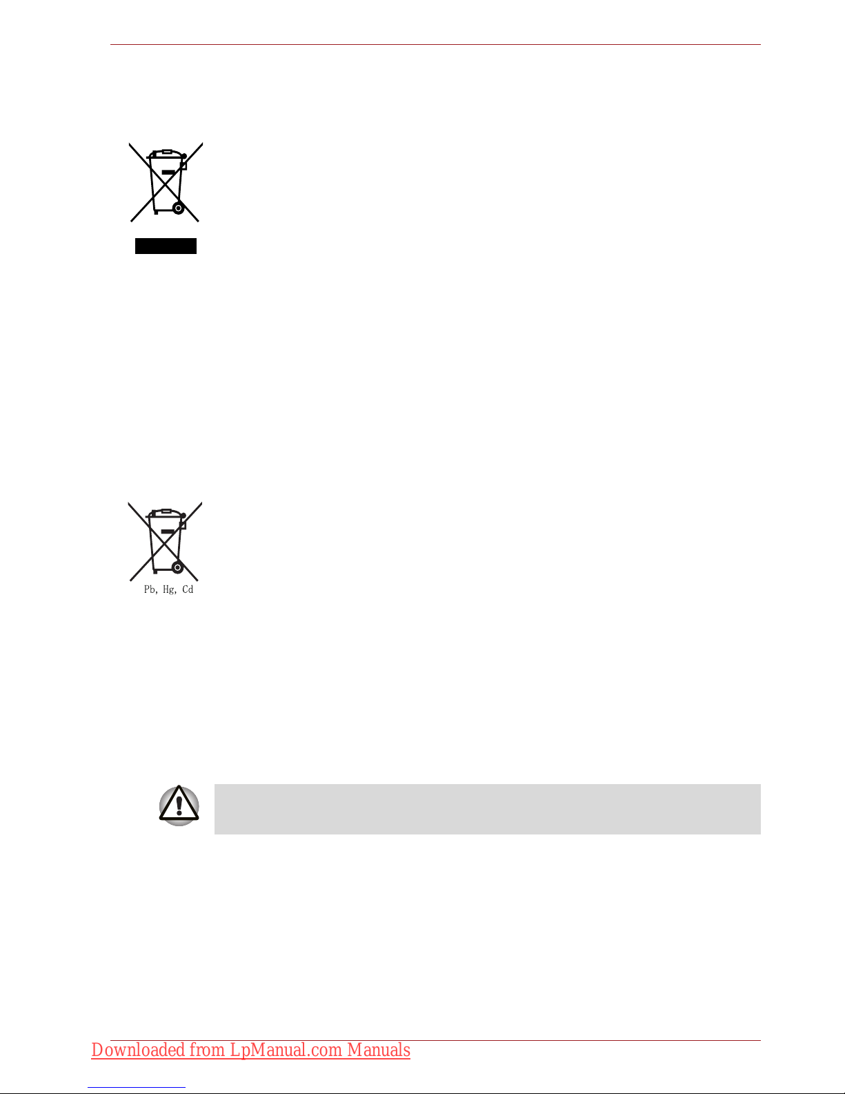
WEEE Dustbin Symbol
The crossed out wheeled dust bin symbol indicates that products must be
collected and disposed of separately from household waste. Integrated
batteries and accumulators can be disposed of with the product. They will
be separated at the recycling centres.
The black bar indicates that the product was placed on the market after
August 13, 2005.
By participating in separate collection of products and batteries, you will
help to assure the proper disposal of products and batteries and thus help
to prevent potential negative consequences for the environment and
human health.
For more detailed information about the collection and recycling
programmes available in your country, please visit our website (http://
eu.computers.toshiba-europe.com) or contact your local city office or the
shop where you purchased the product.
Disposal of batteries and/or accumulators
The crossed out wheeled dust bin symbol indicates that batteries and/or
accumulators must be collected and disposed of separately from
household waste.
If the battery or accumulator contains more than the specified values of
lead (Pb), mercury (Hg), and/or cadmium (Cd) defined in the Battery
Directive (2006/66/EC), then the chemical symbols for lead (Pb), mercury
(Hg) and/or cadmium (Cd) will appear below the crossed out wheeled dust
bin symbol.
By participating in separate collection of batteries, you will help to assure
the proper disposal of products and batteries and thus help to prevent
potential negative consequences for the environment and human health.
For more detailed information about the collection and recycling
programmes available in your country, please visit our website (http://
eu.computers.toshiba-europe.com) or contact your local city office or the
shop where you purchased the product.
This symbol may not be displayed depending on the country and region
where you purchased.
Downloaded from LpManual.com Manuals

User’s Manual xiv
ENERGY STAR® Program
Your Computer model may be ENERGY STAR®
compliant. If the model you purchased is compliant, it is
labeled with the ENERGY STAR logo on the computer and
the following information applies.
TOSHIBA is a partner in the ENERGY STAR Program and
has designed this computer to meet the latest ENERGY
STAR guidelines for energy efficiency. Your computer
ships with the power management options preset to a configuration that will
provide the most stable operating environment and optimum system
performance for both AC power and battery modes.
To conserve energy, your computer is set to enter the low-power Sleep
mode which shuts down the system and display within 15 minutes of
inactivity in AC power mode. TOSHIBA recommends that you leave this
and other energy saving features active, so that your computer will operate
at its maximum energy efficiency. You can wake the computer from Sleep
mode by pressing the power button.
Products that earn the ENERGY STAR prevent greenhouse gas emissions
by meeting strict energy efficiency guidelines set by the US EPA and the
EU Commission. According to the EPA, a computer meeting the new
ENERGY STAR specifications will use between 20% and 50% less energy
depending on how it is used.
Visit http://www.eu-energystar.org or http://www.energystar.gov for more
information regarding the ENERGY STAR Program.
Disposing of the computer and the computer’s batteries
■ Discard this computer in accordance with applicable laws and
regulations. For further information, contact your local government.
■ This computer contains rechargeable batteries. After repeated use, the
batteries will finally lose their ability to hold a charge and you will need
to replace them. Under certain applicable laws and regulation, it may be
illegal to dispose of old batteries by placing them in the trash.
■ Please be kind to our shared environment. Check with your local
government authority for details regarding where to recycle old batteries
or how to dispose of them properly. This product contains mercury.
Disposal of this material may be regulated due to environmental
considerations. For disposal, reuse or recycling information, please
contact your local government.
Downloaded from LpManual.com Manuals
User’s Manual xv
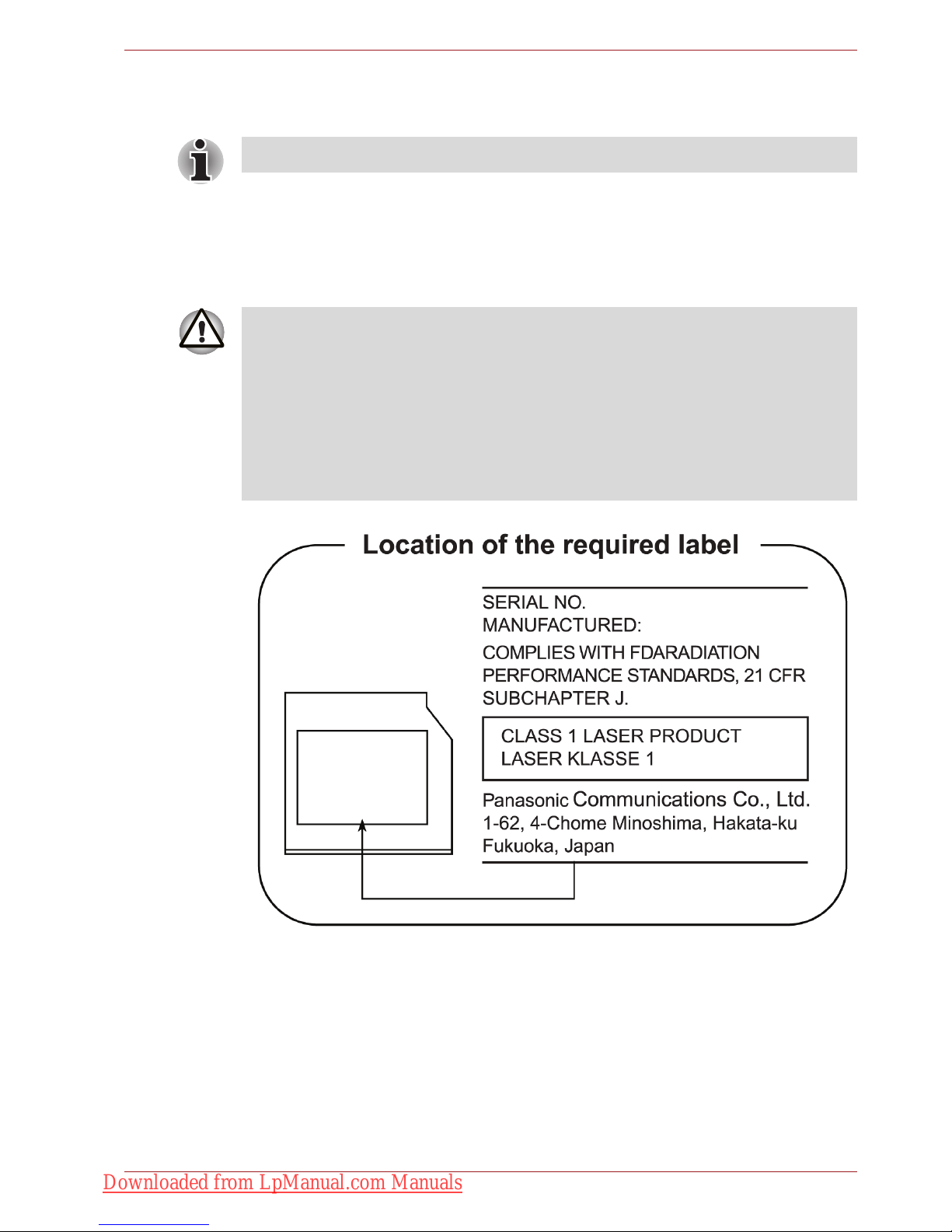
Optical disc drive safety instructions
Panasonic
BD Combo UJ141/BD-R/RE UJ240 with Labelflash™
Be sure to check the international precautions at the end of this section.
■ The BD Combo/BD-R/RE drive employs a laser system. To ensure
proper use of this product, please read this instruction manual carefully
and retain for future reference. Should the unit ever require
maintenance, contact an authorized service location.
■ Use of controls, adjustments or the performance of procedures other
than those specified may result in hazardous radiation exposure.
■ To prevent direct exposure to the laser beam, do not try to open the
enclosure.
Downloaded from LpManual.com Manuals

User’s Manual xvi
Hitach-LG Data Storage
DVD Super Multi GT20N/GT20F with Labelflash™
■ The DVD Super Multi drive employs a laser system. To ensure proper
use of this product, please read this instruction manual carefully and
retain for future reference. Should the unit ever require maintenance,
contact an authorized service location.
■ Use of controls, adjustments or the performance of procedures other
than those specified may result in hazardous radiation exposure.
■ To prevent direct exposure to the laser beam, do not try to open the
enclosure.
Downloaded from LpManual.com Manuals
User’s Manual xvii
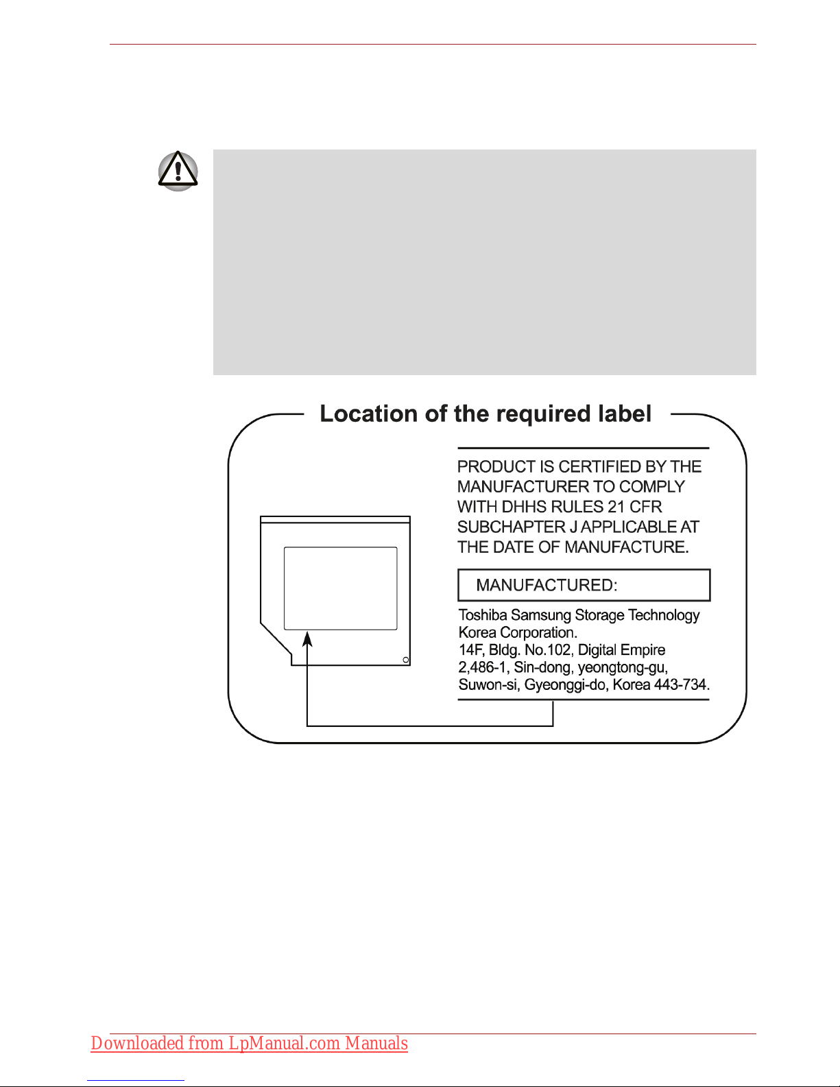
TOSHIBA SAMSUNG STORAGE TECHNOLOGY
DVD Super Multi TS-L633C/TS-L633Y
■ THIS DVD WRITABLE DRIVE EMPLOYS A LASER SYSTEM TO
ENSURE PROPER USE OF THIS PRODUCT, PLEASE READ THIS
INSTRUCTION MANUAL CAREFULLY AND RETAIN FOR FUTURE
REFERENCE. SHOULD THE UNIT EVER REQUIRE MAINTENANCE,
CONTACT AN AUTHORIZED SERVICE LOCATION-SEE SERVICE
PROCEDURE.
■ USE OF CONTROLS OR ADJUSTMENTS OR THE PERFORMANCE
OF PROCEDURES OTHER THAN THOSE SPECIFIED HEREIN MAY
RESULT IN HAZARDOUS RADIATION EXPOSURE.
■ TO PREVENT DIRECT EXPOSURE TO LASER BEAM, DO NOT TRY
TO OPEN THE ENCLOSURE.
Downloaded from LpManual.com Manuals
User’s Manual xviii
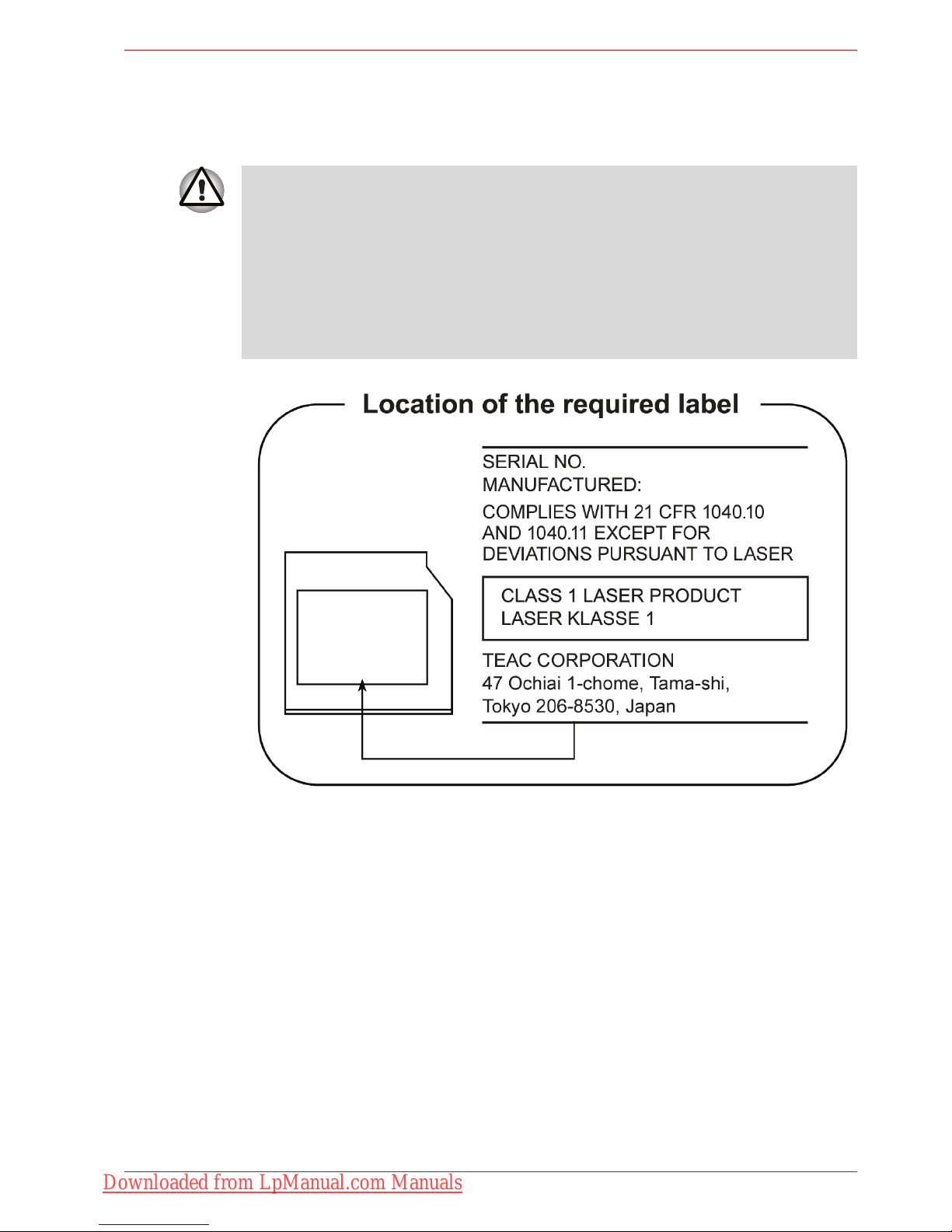
TEAC
DVD Super Multi DV-W28S-VTG/DV-W28S-VTH
Using WinDVD BD for TOSHIBA
Do not sleep or hibernate PC while WinDVD BD for TOSHIBA is running.
When you need it, exit WinDVD BD for TOSHIBA in advance.
■ The DVD Super Multi drive employs a laser system. To ensure proper
use of this product, please read this instruction manual carefully and
retain for future reference. Should the unit ever require maintenance,
contact an authorized service location.
■ Use of controls, adjustments or the performance of procedures other
than those specified may result in hazardous radiation exposure.
■ To prevent direct exposure to the laser beam, do not try to open the
enclosure.
Downloaded from LpManual.com Manuals
User’s Manual xix
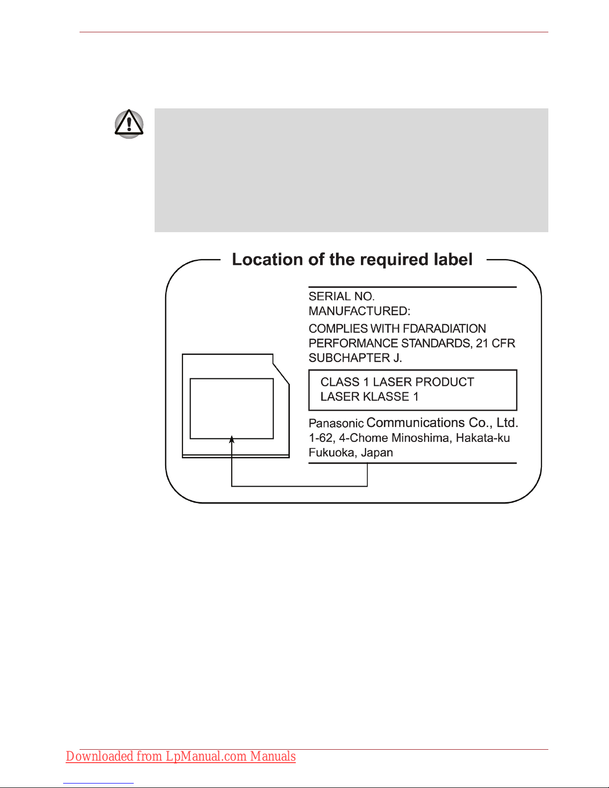
Panasonic
DVD Super Multi UJ890AD/UJ890ED with Labelflash™
■ The DVD Super Multi drive employs a laser system. To ensure proper
use of this product, please read this instruction manual carefully and
retain for future reference. Should the unit ever require maintenance,
contact an authorized service location.
■ Use of controls, adjustments or the performance of procedures other
than those specified may result in hazardous radiation exposure.
■ To prevent direct exposure to the laser beam, do not try to open the
enclosure.
Downloaded from LpManual.com Manuals
User’s Manual xx
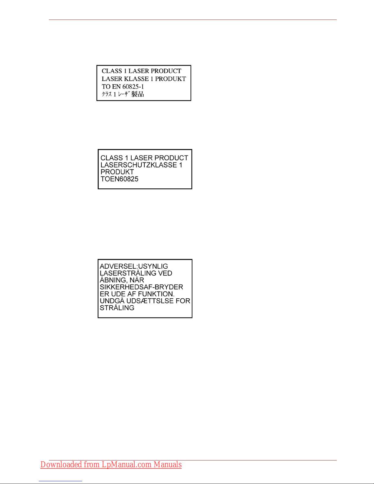
International Precautions
CAUTION: This appliance contains a laser
system and is classified as a "CLASS 1
LASER PRODUCT." To use this model
properly, read the instruction manual
carefully and keep this manual for your
future reference. In case of any trouble
with this model, please contact your
nearest "AUTHORIZED service station."
To prevent direct exposure to the laser
beam, do not try to open the enclosure.
VORSICHT: Dieses Gerät enthält ein
Laser-System und ist als
"LASERSCHUTZKLASSE 1 PRODUKT"
klassifiziert. Für den richtigen Gebrauch
dieses Modells lesen Sie bitte die
Bedienungsanleitung sorgfältig durch und
bewahren diese bitte als Referenz auf.
Falls Probleme mit diesem Modell
auftreten, benachrichtigen Sie bitte die
nächste "autorisierte Service-Vertretung".
Um einen direkten Kontakt mit dem
Laserstrahl zu vermeiden darf das Gerät
nicht geöffnet werden.
ADVARSEL: Denne mærking er anbragt
udvendigt på apparatet og indikerer, at
apparatet arbejder med laserstråler af
klasse 1, hviket betyder, at der anvendes
laserstrlier af svageste klasse, og at man
ikke på apparatets yderside kan bilve
udsat for utilladellg kraftig stråling.
APPARATET BOR KUN ÅBNES AF
FAGFOLK MED SÆRLIGT KENDSKAB
TIL APPARATER MED LASERSTRÅLER!
Indvendigt i apparatet er anbragt den her
gengivne advarselsmækning, som advarer
imod at foretage sådanne indgreb i
apparatet, at man kan komme til at udsatte
sig for laserstråling.
Downloaded from LpManual.com Manuals

User’s Manual xxi
OBS! Apparaten innehåller
laserkomponent som avger laserstråining
överstigande gränsen för laserklass 1.
VAROITUS. Suojakoteloa si saa avata.
Laite sisältää laserdiodin, joka lähetää
näkymätöntä silmilie vaarallista
lasersäteilyä.
CAUTION: USE OF CONTROLS OR
ADJUSTMENTS OR PERFORMANCE
OF PROCEDURES OTHER THAN
THOSE SPECIFIED IN THE OWNER’S
MANUAL MAY RESULT IN HAZARDOUS
RADIATION EXPOSURE.
VORSICHT: DIE VERWENDUNG VON
ANDEREN STEUERUNGEN ODER
EINSTELLUNGEN ODER DAS
DURCHFÜHREN VON ANDEREN
VORGÄNGEN ALS IN DER
BEDIENUNGSANLEITUNG
BESCHRIEBEN KÖNNEN
GEFÄHRLICHE
STRAHLENEXPOSITIONEN ZUR
FOLGE HABEN.
Downloaded from LpManual.com Manuals

User’s Manual xxii
General Precautions
General Precautions
TOSHIBA computers are designed to optimize safety, minimize strain and
withstand the rigors of portability. However, certain precautions should be
observed to further reduce the risk of personal injury or damage to the
computer.
Be certain to read the general precautions below and to note the cautions
included in the text of the manual.
Provide adequate ventilation
■ Always make sure your computer and AC adaptor have adequate
ventilation and are protected from overheating when the power is
turned on or when an AC adaptor is connected to a power outlet (even if
your computer is in Sleep Mode). In this condition, observe the
following:
■ Never cover your computer or AC adaptor with any object.
■ Never place your computer or AC adaptor near a heat source, such
as anelectric blanket or heater.
■ Never cover or block the air vents including those located at the
base of the computer.
■ Always operate your computer on a hard flat surface. Using your
computer on a carpet or other soft material can block the vents.
■ Always provide sufficient space around the computer.
■ Overheating your computer or AC adaptor could cause system failure,
computer or AC adaptor damage or a fire, possibly resulting in serious
injury.
Creating a computer-friendly environment
Place the computer on a flat surface that is large enough for the computer
and any other items you are using, such as a printer.
Leave enough space around the computer and other equipment to provide
adequate ventilation. Otherwise, they may overheat.
Downloaded from LpManual.com Manuals

User’s Manual xxiii
General Precautions
To keep your computer in prime operating condition, protect your work area
from:
■ Dust, moisture, and direct sunlight.
■ Equipment that generates a strong electromagnetic field, such as
stereo speakers (other than speakers that are connected to the
computer) or speakerphones.
■ Rapid changes in temperature or humidity and sources of temperature
change such as air conditioner vents or heaters.
■ Extreme heat, cold, or humidity.
■ Liquids and corrosive chemicals.
Stress injury
Carefully read the Instruction Manual for Safety and Comfort. It contains
information on the prevention of stress injuries to your hands and wrists
that can be caused by extensive keyboard use. Chapter 3, Getting Started,
also includes information on work space design, posture and lighting that
can help reduce physical stress.
Heat injury
■ Avoid prolonged physical contact with the computer. If the computer is
used for long periods, its surface can become very warm. While the
temperature will not feel hot to the touch, if you maintain physical
contact with the computer for a long time, for example if you rest the
computer on your lap or if you keep your hands on the palm rest, your
skin might suffer a low-heat injury.
■ If the computer has been used for a long time, avoid direct contact with
the metal plate supporting the various interface ports as this can
become hot.
■ The surface of the AC adaptor can become hot when in use but this
condition does not indicate a malfunction. If you need to transport the
AC adaptor, you should disconnect it and let it cool before moving it.
■ Do not lay the AC adaptor on a material that is sensitive to heat as the
material could become damaged.
Pressure or impact damage
Do not apply heavy pressure to the computer or subject it to any form of
strong impact as this can damage the computer's components or otherwise
cause it to malfunction.
Downloaded from LpManual.com Manuals

User’s Manual xxiv
General Precautions
ExpressCard overheating
Some PC and ExpressCards can become hot during prolonged use which
may result in errors or instability in the operation of the device in question.
In addition, you should also be careful when you remove a PC or
ExpressCard that has been used for a long time.
Mobile phones
Please be aware that the use of mobile phones can interfere with the audio
system. The operation of the computer will not be impaired in any way, but
it is recommended that a minimum distance of 30cm is maintained between
the computer and a mobile phone that is in use.
Instruction Manual for Safety and Comfort
All important information on the safe and proper use of this computer is
described in the enclosed Instruction Manual for Safety and Comfort. Be
sure to read it before using the computer.
Downloaded from LpManual.com Manuals

User’s Manual xxv
Table of Contents
Table of Contents
Preface
Manual contents . . . . . . . . . . . . . . . . . . . . . . . . . . . . . . . . . . . . . . . . . xxxi
Conventions . . . . . . . . . . . . . . . . . . . . . . . . . . . . . . . . . . . . . . . . . . . . xxxii
Abbreviations . . . . . . . . . . . . . . . . . . . . . . . . . . . . . . . . . . . . . . . . . xxxii
Icons . . . . . . . . . . . . . . . . . . . . . . . . . . . . . . . . . . . . . . . . . . . . . . . . xxxii
Keys . . . . . . . . . . . . . . . . . . . . . . . . . . . . . . . . . . . . . . . . . . . . . . . . xxxii
Key operation . . . . . . . . . . . . . . . . . . . . . . . . . . . . . . . . . . . . . . . . . xxxiii
Display . . . . . . . . . . . . . . . . . . . . . . . . . . . . . . . . . . . . . . . . . . . . . . xxxiii
Messages . . . . . . . . . . . . . . . . . . . . . . . . . . . . . . . . . . . . . . . . . . . . xxxiii
Chapter 1 Introduction
Equipment checklist. . . . . . . . . . . . . . . . . . . . . . . . . . . . . . . . . . . . . . . 1-1
Hardware . . . . . . . . . . . . . . . . . . . . . . . . . . . . . . . . . . . . . . . . . . . . . 1-1
Software . . . . . . . . . . . . . . . . . . . . . . . . . . . . . . . . . . . . . . . . . . . . . . 1-2
Features. . . . . . . . . . . . . . . . . . . . . . . . . . . . . . . . . . . . . . . . . . . . . . . . . 1-3
Special features . . . . . . . . . . . . . . . . . . . . . . . . . . . . . . . . . . . . . . . . . 1-12
TOSHIBA Value Added Package . . . . . . . . . . . . . . . . . . . . . . . . . . . . 1-14
Utilities and Applications. . . . . . . . . . . . . . . . . . . . . . . . . . . . . . . . . . 1-16
Options . . . . . . . . . . . . . . . . . . . . . . . . . . . . . . . . . . . . . . . . . . . . . . . . 1-19
Chapter 2 The Grand Tour
Front with the display closed . . . . . . . . . . . . . . . . . . . . . . . . . . . . . . . 2-1
Left side. . . . . . . . . . . . . . . . . . . . . . . . . . . . . . . . . . . . . . . . . . . . . . . . . 2-3
Right side . . . . . . . . . . . . . . . . . . . . . . . . . . . . . . . . . . . . . . . . . . . . . . . 2-5
Backside . . . . . . . . . . . . . . . . . . . . . . . . . . . . . . . . . . . . . . . . . . . . . . . . 2-7
Underside . . . . . . . . . . . . . . . . . . . . . . . . . . . . . . . . . . . . . . . . . . . . . . . 2-8
Front with the display open. . . . . . . . . . . . . . . . . . . . . . . . . . . . . . . . 2-10
Optical Disc Drive. . . . . . . . . . . . . . . . . . . . . . . . . . . . . . . . . . . . . . . . 2-13
Region codes for BD drive and media . . . . . . . . . . . . . . . . . . . . . . 2-13
Writable discs . . . . . . . . . . . . . . . . . . . . . . . . . . . . . . . . . . . . . . . . . 2-13
CDs. . . . . . . . . . . . . . . . . . . . . . . . . . . . . . . . . . . . . . . . . . . . . . . . . 2-13
Downloaded from LpManual.com Manuals

User’s Manual xxvi
Table of Contents
DVDs. . . . . . . . . . . . . . . . . . . . . . . . . . . . . . . . . . . . . . . . . . . . . . . . 2-13
BDs . . . . . . . . . . . . . . . . . . . . . . . . . . . . . . . . . . . . . . . . . . . . . . . . . 2-13
BD-R/RE drive . . . . . . . . . . . . . . . . . . . . . . . . . . . . . . . . . . . . . . . . 2-14
BD Combo drive . . . . . . . . . . . . . . . . . . . . . . . . . . . . . . . . . . . . . . . 2-15
DVD Super Multi drive . . . . . . . . . . . . . . . . . . . . . . . . . . . . . . . . . . 2-16
AC adaptor . . . . . . . . . . . . . . . . . . . . . . . . . . . . . . . . . . . . . . . . . . . . . 2-17
Remote controller. . . . . . . . . . . . . . . . . . . . . . . . . . . . . . . . . . . . . . . . 2-18
Using the remote controller. . . . . . . . . . . . . . . . . . . . . . . . . . . . . . . 2-21
Installing/Removing batteries . . . . . . . . . . . . . . . . . . . . . . . . . . . . . 2-23
Placing the slim size remote controller . . . . . . . . . . . . . . . . . . . . . . 2-25
Chapter 3 Getting Started
Connecting the AC adaptor . . . . . . . . . . . . . . . . . . . . . . . . . . . . . . . . . 3-2
Opening the display . . . . . . . . . . . . . . . . . . . . . . . . . . . . . . . . . . . . . . . 3-4
Turning on the power . . . . . . . . . . . . . . . . . . . . . . . . . . . . . . . . . . . . . . 3-5
Windows setup . . . . . . . . . . . . . . . . . . . . . . . . . . . . . . . . . . . . . . . . . . . 3-5
Turning off the power . . . . . . . . . . . . . . . . . . . . . . . . . . . . . . . . . . . . . . 3-6
Shut Down mode (Boot mode) . . . . . . . . . . . . . . . . . . . . . . . . . . . . . 3-6
Sleep Mode. . . . . . . . . . . . . . . . . . . . . . . . . . . . . . . . . . . . . . . . . . . . 3-6
Hibernation Mode . . . . . . . . . . . . . . . . . . . . . . . . . . . . . . . . . . . . . . . 3-8
Restarting the computer . . . . . . . . . . . . . . . . . . . . . . . . . . . . . . . . . . . 3-9
System Recovery Options . . . . . . . . . . . . . . . . . . . . . . . . . . . . . . . . . . 3-9
System Recovery Options . . . . . . . . . . . . . . . . . . . . . . . . . . . . . . . 3-10
Create Optical Recovery Discs . . . . . . . . . . . . . . . . . . . . . . . . . . . . . 3-10
Restoring the preinstalled software from the Recovery HDD . . . . 3-11
Restoring the preinstalled software from Recovery Media . . . . . . 3-12
Chapter 4 Operating Basics
Using the TouchPad . . . . . . . . . . . . . . . . . . . . . . . . . . . . . . . . . . . . . . . 4-1
Touch Pad Gesture . . . . . . . . . . . . . . . . . . . . . . . . . . . . . . . . . . . . . . 4-2
Using the fingerprint sensor . . . . . . . . . . . . . . . . . . . . . . . . . . . . . . . . 4-3
How to swipe the finger. . . . . . . . . . . . . . . . . . . . . . . . . . . . . . . . . . . 4-4
Points to note about the fingerprint sensor . . . . . . . . . . . . . . . . . . . . 4-5
How to delete the fingerprint data. . . . . . . . . . . . . . . . . . . . . . . . . . . 4-6
Fingerprint sensor limitations . . . . . . . . . . . . . . . . . . . . . . . . . . . . . . 4-6
Points to note about the fingerprint utility . . . . . . . . . . . . . . . . . . . . . 4-7
Set up procedure . . . . . . . . . . . . . . . . . . . . . . . . . . . . . . . . . . . . . . . 4-7
Windows logon via fingerprint authentication . . . . . . . . . . . . . . . . . . 4-8
Fingerprint system boot authentication. . . . . . . . . . . . . . . . . . . . . . . 4-8
Fingerprint Single Sign-On feature . . . . . . . . . . . . . . . . . . . . . . . . . . 4-9
USB Sleep and Charge function . . . . . . . . . . . . . . . . . . . . . . . . . . . . 4-10
Starting the USB Sleep and Charge Utility . . . . . . . . . . . . . . . . . . . .4-11
Using the Web Camera. . . . . . . . . . . . . . . . . . . . . . . . . . . . . . . . . . . . 4-12
Using the software . . . . . . . . . . . . . . . . . . . . . . . . . . . . . . . . . . . . . 4-13
Downloaded from LpManual.com Manuals

User’s Manual xxvii
Table of Contents
Using the microphone . . . . . . . . . . . . . . . . . . . . . . . . . . . . . . . . . . . . 4-14
Using the TOSHIBA Face Recognition . . . . . . . . . . . . . . . . . . . . . . . 4-14
Disclaimer . . . . . . . . . . . . . . . . . . . . . . . . . . . . . . . . . . . . . . . . . . . . 4-15
How to register the Face Recognition Data . . . . . . . . . . . . . . . . . . 4-15
How to Delete the Face Recognition Data . . . . . . . . . . . . . . . . . . . 4-16
How to launch the help file . . . . . . . . . . . . . . . . . . . . . . . . . . . . . . . 4-17
Windows Logon via TOSHIBA Face Recognition . . . . . . . . . . . . . . 4-17
Using the optical disc drive. . . . . . . . . . . . . . . . . . . . . . . . . . . . . . . . 4-17
Loading discs . . . . . . . . . . . . . . . . . . . . . . . . . . . . . . . . . . . . . . . . . 4-18
Removing discs. . . . . . . . . . . . . . . . . . . . . . . . . . . . . . . . . . . . . . . . 4-22
Writing CD/DVD/BDs . . . . . . . . . . . . . . . . . . . . . . . . . . . . . . . . . . . . . 4-23
Important message . . . . . . . . . . . . . . . . . . . . . . . . . . . . . . . . . . . . . 4-23
Before writing or rewriting with the BD-R/RE drive . . . . . . . . . . . . . 4-23
Before writing or rewriting with the BD Combo drive . . . . . . . . . . . 4-25
Before writing or rewriting with the DVD Super Multi drive . . . . . . . 4-26
When writing or rewriting . . . . . . . . . . . . . . . . . . . . . . . . . . . . . . . . 4-29
Disclaimer (DVD Super Multi drive or BD-R/RE drive) . . . . . . . . . . 4-29
Data Verification . . . . . . . . . . . . . . . . . . . . . . . . . . . . . . . . . . . . . . . . . 4-30
How to learn more about TOSHIBA Disc Creator. . . . . . . . . . . . . . 4-30
Video . . . . . . . . . . . . . . . . . . . . . . . . . . . . . . . . . . . . . . . . . . . . . . . . . . 4-30
When using Corel DVD MovieFactory® for TOSHIBA: . . . . . . . . . . 4-30
How to make a Labelflash DVD . . . . . . . . . . . . . . . . . . . . . . . . . . . 4-30
How to make a Blu-ray disc Movie . . . . . . . . . . . . . . . . . . . . . . . . . 4-30
How to make a DVD-Video. . . . . . . . . . . . . . . . . . . . . . . . . . . . . . . 4-31
How to learn more about Corel MovieFactory . . . . . . . . . . . . . . . . 4-31
Important information for use . . . . . . . . . . . . . . . . . . . . . . . . . . . . . 4-31
TOSHIBA DVD Player . . . . . . . . . . . . . . . . . . . . . . . . . . . . . . . . . . . . . 4-33
Using WinDVD BD for TOSHIBA . . . . . . . . . . . . . . . . . . . . . . . . . . . . 4-35
Media care . . . . . . . . . . . . . . . . . . . . . . . . . . . . . . . . . . . . . . . . . . . . . . 4-37
CD/DVD/BD . . . . . . . . . . . . . . . . . . . . . . . . . . . . . . . . . . . . . . . . . . 4-37
Modem . . . . . . . . . . . . . . . . . . . . . . . . . . . . . . . . . . . . . . . . . . . . . . . . . 4-38
Region selection . . . . . . . . . . . . . . . . . . . . . . . . . . . . . . . . . . . . . . . 4-38
Properties menu . . . . . . . . . . . . . . . . . . . . . . . . . . . . . . . . . . . . . . . 4-38
Settings. . . . . . . . . . . . . . . . . . . . . . . . . . . . . . . . . . . . . . . . . . . . . . 4-39
Modem Selection . . . . . . . . . . . . . . . . . . . . . . . . . . . . . . . . . . . . . . 4-39
Dialing Properties . . . . . . . . . . . . . . . . . . . . . . . . . . . . . . . . . . . . . . 4-39
Connecting . . . . . . . . . . . . . . . . . . . . . . . . . . . . . . . . . . . . . . . . . . . 4-39
Disconnecting . . . . . . . . . . . . . . . . . . . . . . . . . . . . . . . . . . . . . . . . . 4-40
Using the FM tuner . . . . . . . . . . . . . . . . . . . . . . . . . . . . . . . . . . . . . . . 4-41
Wireless communications . . . . . . . . . . . . . . . . . . . . . . . . . . . . . . . . . 4-42
Wireless LAN . . . . . . . . . . . . . . . . . . . . . . . . . . . . . . . . . . . . . . . . . 4-42
Security. . . . . . . . . . . . . . . . . . . . . . . . . . . . . . . . . . . . . . . . . . . . . . 4-43
Downloaded from LpManual.com Manuals

User’s Manual xxviii
Table of Contents
Bluetooth Stack for Windows by TOSHIBA (depends on the model you
purchased) . . . . . . . . . . . . . . . . . . . . . . . . . . . . . . . . . . . . . . . . . . . 4-43
Wireless communication switch . . . . . . . . . . . . . . . . . . . . . . . . . . . 4-44
Wireless activity LED . . . . . . . . . . . . . . . . . . . . . . . . . . . . . . . . . . . 4-44
LAN . . . . . . . . . . . . . . . . . . . . . . . . . . . . . . . . . . . . . . . . . . . . . . . . . . . 4-44
LAN cable types . . . . . . . . . . . . . . . . . . . . . . . . . . . . . . . . . . . . . . . 4-44
Connecting LAN cable . . . . . . . . . . . . . . . . . . . . . . . . . . . . . . . . . . 4-45
Disconnecting LAN cable . . . . . . . . . . . . . . . . . . . . . . . . . . . . . . . . 4-45
Cleaning the computer. . . . . . . . . . . . . . . . . . . . . . . . . . . . . . . . . . . . 4-45
Moving the computer . . . . . . . . . . . . . . . . . . . . . . . . . . . . . . . . . . . . . 4-46
Using the Hard Disk Drive (HDD) Protection . . . . . . . . . . . . . . . . . 4-46
TOSHIBA HDD Protection Properties. . . . . . . . . . . . . . . . . . . . . . . 4-47
Details. . . . . . . . . . . . . . . . . . . . . . . . . . . . . . . . . . . . . . . . . . . . . . . 4-48
Chapter 5 The Keyboard
Typewriter keys. . . . . . . . . . . . . . . . . . . . . . . . . . . . . . . . . . . . . . . . . . . 5-1
F1 ... F12 function keys . . . . . . . . . . . . . . . . . . . . . . . . . . . . . . . . . . . . 5-2
Soft keys: Fn key combinations . . . . . . . . . . . . . . . . . . . . . . . . . . . . . 5-2
Emulating keys on enhanced keyboard . . . . . . . . . . . . . . . . . . . . . . 5-2
Hot keys. . . . . . . . . . . . . . . . . . . . . . . . . . . . . . . . . . . . . . . . . . . . . . . . . 5-3
Fn Sticky key (Depends on the model you purchased). . . . . . . . . . . 5-4
Windows special keys . . . . . . . . . . . . . . . . . . . . . . . . . . . . . . . . . . . . . 5-5
Generating ASCII characters. . . . . . . . . . . . . . . . . . . . . . . . . . . . . . . . 5-5
Chapter 6 Power and Power-Up Modes
Power conditions . . . . . . . . . . . . . . . . . . . . . . . . . . . . . . . . . . . . . . . . . 6-1
Power indicators. . . . . . . . . . . . . . . . . . . . . . . . . . . . . . . . . . . . . . . . . . 6-2
Battery indicator . . . . . . . . . . . . . . . . . . . . . . . . . . . . . . . . . . . . . . . . 6-2
Power indicator . . . . . . . . . . . . . . . . . . . . . . . . . . . . . . . . . . . . . . . . . 6-2
Battery types. . . . . . . . . . . . . . . . . . . . . . . . . . . . . . . . . . . . . . . . . . . . . 6-3
Battery pack . . . . . . . . . . . . . . . . . . . . . . . . . . . . . . . . . . . . . . . . . . . 6-3
Real Time Clock battery . . . . . . . . . . . . . . . . . . . . . . . . . . . . . . . . . . 6-4
Care and use of the battery pack . . . . . . . . . . . . . . . . . . . . . . . . . . . . 6-6
Charging the batteries. . . . . . . . . . . . . . . . . . . . . . . . . . . . . . . . . . . . 6-6
Monitoring battery capacity. . . . . . . . . . . . . . . . . . . . . . . . . . . . . . . . 6-8
Maximizing battery operating time . . . . . . . . . . . . . . . . . . . . . . . . . . 6-8
Retaining data with power off . . . . . . . . . . . . . . . . . . . . . . . . . . . . . . 6-9
Extending battery life . . . . . . . . . . . . . . . . . . . . . . . . . . . . . . . . . . . . 6-9
Replacing the battery pack . . . . . . . . . . . . . . . . . . . . . . . . . . . . . . . . 6-10
Removing the battery pack . . . . . . . . . . . . . . . . . . . . . . . . . . . . . . . 6-10
Installing the battery pack . . . . . . . . . . . . . . . . . . . . . . . . . . . . . . . . .6-11
Starting the computer by password . . . . . . . . . . . . . . . . . . . . . . . . . 6-12
Power-up modes. . . . . . . . . . . . . . . . . . . . . . . . . . . . . . . . . . . . . . . . . 6-13
Hot keys . . . . . . . . . . . . . . . . . . . . . . . . . . . . . . . . . . . . . . . . . . . . . 6-13
Downloaded from LpManual.com Manuals

User’s Manual xxix
Table of Contents
Panel power off/on . . . . . . . . . . . . . . . . . . . . . . . . . . . . . . . . . . . . . . . 6-13
System Auto Off . . . . . . . . . . . . . . . . . . . . . . . . . . . . . . . . . . . . . . . . . 6-13
Chapter 7 HW Setup
Accessing HW Setup . . . . . . . . . . . . . . . . . . . . . . . . . . . . . . . . . . . . . . 7-1
HW Setup Window . . . . . . . . . . . . . . . . . . . . . . . . . . . . . . . . . . . . . . . . 7-1
Chapter 8 Optional Devices
ExpressCard . . . . . . . . . . . . . . . . . . . . . . . . . . . . . . . . . . . . . . . . . . . . . 8-2
Inserting an ExpressCard . . . . . . . . . . . . . . . . . . . . . . . . . . . . . . . . . 8-2
Removing an ExpressCard. . . . . . . . . . . . . . . . . . . . . . . . . . . . . . . . 8-3
SD/SDHC/MMC/MEMORY STICK / MEMORY STICK PRO/xD Memory
cards . . . . . . . . . . . . . . . . . . . . . . . . . . . . . . . . . . . . . . . . . . . . . . . . . . . 8-4
Installing a memory card. . . . . . . . . . . . . . . . . . . . . . . . . . . . . . . . . . 8-5
Removing a memory card. . . . . . . . . . . . . . . . . . . . . . . . . . . . . . . . . 8-5
Memory card care . . . . . . . . . . . . . . . . . . . . . . . . . . . . . . . . . . . . . . . 8-6
Memory expansion . . . . . . . . . . . . . . . . . . . . . . . . . . . . . . . . . . . . . . . . 8-7
Installing a memory module . . . . . . . . . . . . . . . . . . . . . . . . . . . . . . . 8-7
Removing a memory module . . . . . . . . . . . . . . . . . . . . . . . . . . . . . 8-10
Additional battery pack . . . . . . . . . . . . . . . . . . . . . . . . . . . . . . . . . . . 8-11
Additional AC adaptor . . . . . . . . . . . . . . . . . . . . . . . . . . . . . . . . . . . . 8-11
External monitor . . . . . . . . . . . . . . . . . . . . . . . . . . . . . . . . . . . . . . . . . 8-12
HDMI . . . . . . . . . . . . . . . . . . . . . . . . . . . . . . . . . . . . . . . . . . . . . . . . . . 8-12
Setting for display video on HDMI. . . . . . . . . . . . . . . . . . . . . . . . . . 8-13
Settings for audio on HDMI. . . . . . . . . . . . . . . . . . . . . . . . . . . . . . . 8-13
i.LINK (IEEE1394) . . . . . . . . . . . . . . . . . . . . . . . . . . . . . . . . . . . . . . . . 8-13
Precautions. . . . . . . . . . . . . . . . . . . . . . . . . . . . . . . . . . . . . . . . . . . 8-14
Connecting . . . . . . . . . . . . . . . . . . . . . . . . . . . . . . . . . . . . . . . . . . . 8-14
Disconnecting . . . . . . . . . . . . . . . . . . . . . . . . . . . . . . . . . . . . . . . . . 8-14
eSATA (External Serial ATA) . . . . . . . . . . . . . . . . . . . . . . . . . . . . . . . 8-16
Connecting an eSATA device . . . . . . . . . . . . . . . . . . . . . . . . . . . . . 8-16
Disconnecting an eSATA device. . . . . . . . . . . . . . . . . . . . . . . . . . . 8-17
Security lock . . . . . . . . . . . . . . . . . . . . . . . . . . . . . . . . . . . . . . . . . . . . 8-17
Chapter 9 Troubleshooting
Problem solving process. . . . . . . . . . . . . . . . . . . . . . . . . . . . . . . . . . . 9-1
Preliminary checklist . . . . . . . . . . . . . . . . . . . . . . . . . . . . . . . . . . . . . 9-2
Analyzing the problem . . . . . . . . . . . . . . . . . . . . . . . . . . . . . . . . . . . 9-2
Hardware and system checklist . . . . . . . . . . . . . . . . . . . . . . . . . . . . . 9-3
System start-up. . . . . . . . . . . . . . . . . . . . . . . . . . . . . . . . . . . . . . . . . 9-3
Self test. . . . . . . . . . . . . . . . . . . . . . . . . . . . . . . . . . . . . . . . . . . . . . . 9-4
Power . . . . . . . . . . . . . . . . . . . . . . . . . . . . . . . . . . . . . . . . . . . . . . . . 9-4
Disposing of PC and PC batteries . . . . . . . . . . . . . . . . . . . . . . . . . . 9-6
Real Time Clock . . . . . . . . . . . . . . . . . . . . . . . . . . . . . . . . . . . . . . . . 9-7
Keyboard. . . . . . . . . . . . . . . . . . . . . . . . . . . . . . . . . . . . . . . . . . . . . . 9-7
Downloaded from LpManual.com Manuals

User’s Manual xxx
Table of Contents
LCD panel . . . . . . . . . . . . . . . . . . . . . . . . . . . . . . . . . . . . . . . . . . . . . 9-8
Solid State drive . . . . . . . . . . . . . . . . . . . . . . . . . . . . . . . . . . . . . . . . 9-9
Recovery Media Creator. . . . . . . . . . . . . . . . . . . . . . . . . . . . . . . . . . 9-9
Hard disk drive . . . . . . . . . . . . . . . . . . . . . . . . . . . . . . . . . . . . . . . . . 9-9
BD drive . . . . . . . . . . . . . . . . . . . . . . . . . . . . . . . . . . . . . . . . . . . . . 9-10
Pointing device . . . . . . . . . . . . . . . . . . . . . . . . . . . . . . . . . . . . . . . . 9-12
USB. . . . . . . . . . . . . . . . . . . . . . . . . . . . . . . . . . . . . . . . . . . . . . . . . 9-14
USB Sleep and Charge function. . . . . . . . . . . . . . . . . . . . . . . . . . . 9-15
Memory expansion . . . . . . . . . . . . . . . . . . . . . . . . . . . . . . . . . . . . . 9-16
Sound system . . . . . . . . . . . . . . . . . . . . . . . . . . . . . . . . . . . . . . . . . 9-17
Monitor . . . . . . . . . . . . . . . . . . . . . . . . . . . . . . . . . . . . . . . . . . . . . . 9-17
Modem . . . . . . . . . . . . . . . . . . . . . . . . . . . . . . . . . . . . . . . . . . . . . . 9-17
LAN. . . . . . . . . . . . . . . . . . . . . . . . . . . . . . . . . . . . . . . . . . . . . . . . . 9-18
Wireless LAN . . . . . . . . . . . . . . . . . . . . . . . . . . . . . . . . . . . . . . . . . 9-18
Fingerprint sensor . . . . . . . . . . . . . . . . . . . . . . . . . . . . . . . . . . . . . . 9-19
ExpressCard . . . . . . . . . . . . . . . . . . . . . . . . . . . . . . . . . . . . . . . . . . 9-19
TOSHIBA support . . . . . . . . . . . . . . . . . . . . . . . . . . . . . . . . . . . . . . . . 9-20
Before you call . . . . . . . . . . . . . . . . . . . . . . . . . . . . . . . . . . . . . . . . 9-20
Where to write. . . . . . . . . . . . . . . . . . . . . . . . . . . . . . . . . . . . . . . . . 9-21
Appendix A Specifications
Appendix B Display Controller
Appendix C Wireless LAN
Appendix D AC Power Cord and Connectors
Appendix E Disclaimers
Appendix F TOSHIBA PC Health Monitor
Starting the TOSHIBA PC Health Monitor. . . . . . . . . . . . . . . . . . . . . . E-2
Glossary
Index
Downloaded from LpManual.com Manuals

User’s Manual xxxi
Preface
Preface
Congratulations on your purchase of the TOSHIBA Satellite P500 / Satellite
P505 / Satellite P507, Qosmio X505, Qosmio X500, Qosmio G60, Satellite
P500D / Satellite P505D / Satellite P507D Series Series computer. This
powerful notebook computer provides excellent expansion capability,
including multimedia devices, and it is designed to provide years of reliable,
high-performance computing.
This manual tells you how to set up and begin using your TOSHIBA
Satellite P500 / Satellite P505 / Satellite P507, Qosmio X505, Qosmio
X500, Qosmio G60, Satellite P500D / Satellite P505D / Satellite P507D
Series Series computer. It also provides detailed information on configuring
your computer, basic operations and care, using optional devices and
troubleshooting.
If you are a new user of computers or if you’re new to portable computing,
first read over the Introduction and The Grand Tour chapters to familiarize
yourself with the computer's features, components and accessory devices.
Then read Getting Started for step-by-step instructions on setting up your
computer.
If you are an experienced computer user, please continue reading the
preface to learn how this manual is organized, then become acquainted
with this manual by browsing through its pages. Be sure to look over the
Specifications section of the Introduction, to learn about features that are
uncommon or unique to the computer. If you are going to install
ExpressCards or connect external devices such as a monitor, be sure to
read Chapter 8, Optional Devices.
Manual contents
This manual is composed of the following nine chapters, five appendixes, a
glossary and an index.
Chapter 1, Introduction, is an overview of the computer's features,
capabilities, and options.
Chapter 2, The Grand Tour, identifies the components of the computer and
briefly explains how they function.
Chapter 3, Getting Started, provides a quick overview of how to begin
operating your computer and gives tips on safety and designing your work
area.
Downloaded from LpManual.com Manuals

User’s Manual xxxii
Preface
Chapter 4, Operating Basics, includes instructions on using the following
devices: TouchPad, Sound System, optical media drives, modem, wireless
communication and LAN. It also provides tips on care of the computer, and
CD/DVDs.
Chapter 5, The Keyboard, describes special keyboard functions including
hot keys.
Chapter 6, Power and Power-Up Modes, gives details on the computer's
power resources and battery save modes.
Chapter 7, HW Setup explains how to configure the computer using the
HW Setup program.
Chapter 8, Optional Devices, describes the optional hardware available.
Chapter 9, Troubleshooting, provides helpful information on how to perform
some diagnostic tests, and suggests courses of action if the computer
doesn’t seem to be working properly.
The Appendices provide technical information about your computer.
The Glossary defines general computer terminology and includes a list of
acronyms used in the text.
The Index quickly directs you to the information contained in this manual.
Conventions
This manual uses the following formats to describe, identify, and highlight
terms and operating procedures.
Abbreviations
On first appearance, and whenever necessary for clarity, abbreviations are
enclosed in parenthesis following their definition. For example: Read Only
Memory (ROM). Acronyms are also defined in the Glossary.
Icons
Icons identify ports, dials, and other parts of your computer. The indicator
panel also uses icons to identify the components it is providing information
on.
Keys
The keyboard keys are used in the text to describe many computer
operations. A distinctive typeface identifies the key top symbols as they
appear on the keyboard. For example, Enter identifies the Enter key.
Downloaded from LpManual.com Manuals

User’s Manual xxxiii
Preface
Key operation
Some operations require you to simultaneously use two or more keys. We
identify such operations by the key top symbols separated by a plus sign
(+). For example, Ctrl + C means you must hold down Ctrl and at the same
time press C. If three keys are used, hold down the first two and at the
same time press the third.
Display
Messages
Messages are used in this manual to bring important information to your
attention. Each type of message is identified as shown below.
Terminology
This term is defined in this document as follows:
ABC When procedures require an action such as
clicking an icon or entering text, the icon’s name
or the text you are to type in is represented in the
type face you see to the left.
ABC
Names of windows or icons or text generated by
the computer that appears on its display screen
is presented in the type face you see to the left.
Pay attention! A caution informs you that improper use of equipment or
failure to follow instructions may cause data loss or damage your
equipment.
Please read. A note is a hint or advice that helps you make best use of
your equipment.
Indicates a potentially hazardous situation, which could result in death or
serious injury, if you do not follow instructions.
Start
The word “Start” refers to the button in
Microsoft
®
Windows.
Downloaded from LpManual.com Manuals

User’s Manual 1-1
Introduction
Chapter 1
Introduction
This chapter provides an equipment checklist, and it identifies the
computer's features, options and accessories.
Equipment checklist
Carefully unpack your computer. Save the box and packing materials for
future use.
Hardware
Check to make sure you have all the following items:
■ TOSHIBA Satellite P500 / Satellite P505 / Satellite P507, Qosmio X505,
Qosmio X500, Qosmio G60, Satellite P500D / Satellite P505D / Satellite
P507D Series Series Portable Personal Computer
■ Universal AC adaptor and power cord
Some of the features described in this manual may not function properly if
you use an operating system that was not pre-installed by TOSHIBA.
It is necessary to install the battery to use this computer. Refer to Installing
the battery pack section in Chapter 3, Getting Started.
Downloaded from LpManual.com Manuals

User’s Manual 1-2
Introduction
Software
The following software is preinstalled:
■ Windows
®
7
■ Microsoft Internet Explorer
■ TOSHIBA Value Added Package
■ TOSHIBA Hardware Setup
■ TOSHIBA Supervisor Password
■ TOSHIBA Assist
■ TOSHIBA ConfigFree
■ TOSHIBA HDD Protection
■ TOSHIBA DVD PLAYER
■ TOSHIBA FingerPrint Utility (FingerPrint support model only)
■ TOSHIBA Disc Creator
■ TOSHIBA Recovery Media Creator
■ TOSHIBA Face Recognition
■ WinDVD BD for TOSHIBA
■ Corel MovieFactory
®
for TOSHIBA
■ TOSHIBA PC Health Monitor
■ TOSHIBA USB Sleep and Charge Utility
■ TOSHIBA eco Utility
■ Online Manual
Other software may be preinstalled dependant on the model purchased.
Documentation
■ TOSHIBA Satellite P500 / Satellite P505 / Satellite P507, Qosmio
X505, Qosmio X500, Qosmio G60, Satellite P500D / Satellite
P505D / Satellite P507D Series Series Personal Computer User
Information Guide
■ International Limited Warranty (ILW) Instruction (This instruction is
included only with computers sold in ILW supported areas.)
■ Instruction Manual for Safety and Comfort
■ End User License Agreement
If any of the items are missing or damaged, contact your dealer
immediately.
Downloaded from LpManual.com Manuals

User’s Manual 1-3
Introduction
Features
Please visit your region’s web site for the configuration details of the model
that you have purchased.
Processor
Memory
Built-in Your computer is equipped with one processor
and processor type varies depending on model.
To check which type of processor is included in
your model, open the TOSHIBA PC Diagnostic
Tool Utility by clicking Start J All programs J
TOSHIBA J Utilities J TOSHIBA PC
diagnostic Tool.
Chipset Depends on the model you purchased.
Mobile Intel
®
HM55/HM57/PM55/PM57/GM45/
PM45 Express Chipset
AMD RS880MC/RS880M/RX881 Chipset
Disclaimer (CPU)*1
For more information regarding CPU, please refer to the Disclaimers
section in Appendix E or click the *1 above.
Slots PC2-6400 or PC3-8500 1GB, 2GB, 4GB memory
modules can be installed in the two memory
slots. Maximum system memory size and speed
depend on the model you purchased.
Disclaimer (Memory (Main System))*2
For more information regarding Memory (Main System), please refer to the
Disclaimers section in Appendix E or click the *2 above.
Downloaded from LpManual.com Manuals

User’s Manual 1-4
Introduction
Video RAM Video RAM depends on the model you
purchased.
Mobile Intel® GM45 Express Chipset model:
Video RAM capacity shares with main memory,
and the proportion depends on Dynamic Video
Memory Technology.
Mobile Intel
®
GM45 Express Chipset model in
graphic chip by NVIDIA
®
GeForce® G 210M:
External 512MB
Mobile Intel® GM45 Express Chipset model in
graphic chip by NVIDIA
®
GeForce® GT 230M:
External 1GB
Mobile Intel® HM55 Express Chipset model in
graphic chip by NVIDIA® GeForce® GT 330M:
External 512MB
Mobile Intel® HM55 Express Chipset model in
graphic chip by NVIDIA® GeForce® GT 330M:
External 1GB
Mobile Intel® PM55/PM57 Express Chipset
model in graphic by NVIDIA® GeForce® GTS
250M: External 1GB
Mobile Intel® PM55/PM57 Express Chipset
model in graphic by NVIDIA® GeForce® GTS
360M: External 1GB
AMD M780G Chipset model/
AMD M780V Chipset model/
AMD M880G Chipset model/
AMD M860G Chipset model:
Video RAM capacity shares with main memory,
and the proportion depends on ATI
HyperMemory™.
AMD M780G Chipset model/
AMD M880G Chipset model/
AMD M870 Chipset model in graphic chip by ATI
Mobility Radeon™ HD 4570: External 512MB
AMD M780G Chipset model/
AMD M880G Chipset model/
AMD M870 Chipset model in graphic chip by ATI
Mobility Radeon™ HD 4650: External 1GB
Downloaded from LpManual.com Manuals

User’s Manual 1-5
Introduction
Power
Disks
Battery Pack Your computer is powered by a rechargeable
lithium-ion battery pack.
Disclaimer (Battery Life)*3
For more information regarding Battery Life, please refer to the
Disclaimers section in Appendix E or click the *3 above.
RTC Battery The internal RTC battery backs up the Real Time
Clock and calendar.
AC Adaptor The universal AC adaptor provides power to the
system and recharges the batteries when they
are low. It comes with a detachable power cord.
Because it is universal, it can receive a range of
AC voltage from 100 to 240 volts; however, the
output current varies among different models.
Using the wrong model can damage your
computer. Refer to the AC adaptor section in
Chapter 2, The Grand Tour.
Solid State Drive Depends on the model you purchased.
■ 64GB
Hard disk Drive Depends on the model you purchased.
■ 160GB
■ 200GB
■ 250GB
■ 320GB
■ 400GB
■ 500GB
■ 640GB
Additional hard disk drive sizes may be introduced.
Downloaded from LpManual.com Manuals

User’s Manual 1-6
Introduction
BD-R/RE drive with
Labelflash™
Some models are equipped with a full-size BD-R/
RE drive module that lets you record data to
rewritable CD/DVD/BDs. It reads BD-ROM discs
at maximum 6 speed, BD-ROM (DL) discs at
maximum 6 speed, DVD-ROM's at maximum 8
speed and CD-ROM's at maximum 24 speed. It
writes CD-R's at up to 24 speed, CD-RW's at up
to 4 speed, DVD-R's at maximum 8 speed, DVDRW's at maximum 6 speed. DVD+R's at
maximum 8 speed, DVD+RW's at maximum 8
speed, DVD+R(DL) discs at maximum 4 speed
and DVD-R(DL) discs at maximun 4 speed and
DVD-RAM discs at maximum 5 speed. BD-R
discs at maximum 6 speed, BD-R (DL) discs at
maximum 4 speed, BD-RE discs at maximum 2
speed, and BD-RE (DL) discs at maximum 2
speed. It supports the following formats:
■ BD-ROM
■ BD-ROM (DL)
■ BD-R
■ BD-R (DL)
■ BD-RE
■ BD-RE (DL)
■ DVD-ROM
■ DVD-Video
■ DVD-R
■ DVD-RW
■ DVD+R
■ DVD+RW
■ DVD-RAM
■ DVD+R DL
■ DVD-R DL
■ CD-DA
■ CD-Text
■ Photo CD (single/multi-session)
■ CD-ROM Mode 1, Mode 2
■ CD-ROMXA Mode 2 (Form1, Form2)
■ Enhanced CD (CD-EXTRA)
■ CD-G (Audio CD only)
■ Addressing Method 2
Downloaded from LpManual.com Manuals

User’s Manual 1-7
Introduction
BD Combo drive with
Labelflash™
Some models are equipped with a full-size BD
Combo drive module that lets you record data to
rewritable CD/DVDs. It reads BD-ROM discs at
maximum 6 speed, BD-ROM (DL) discs at
maximum 6 speed, DVD-ROM's at maximum 8
speed and CD-ROM's at maximum 24 speed. It
writes CD-R's at up to 24 speed, CD-RW's at up
to 4 speed, DVD-R's at maximum 8 speed, DVDRW's at maximum 6 speed. DVD+R's at
maximum 8 speed, DVD+RW's at maximum 8
speed, DVD+R(DL) discs at maximum 4 speed
and DVD-R(DL) discs at maximun 4 speed and
DVD-RAM discs at maximum 5 speed. It
supports the following formats:
■ BD-ROM
■ BD-ROM (DL)
■ BD-R
■ BD-R (DL)
■ BD-RE
■ BD-RE (DL)
■ DVD-ROM
■ DVD-Video
■ DVD-R
■ DVD-RW
■ DVD+R
■ DVD+RW
■ DVD-RAM
■ DVD+R DL
■ DVD-R DL
■ CD-DA
■ CD-Text
■ Photo CD (single/multi-session)
■ CD-ROM Mode 1, Mode 2
■ CD-ROMXA Mode 2 (Form1, Form2)
■ Enhanced CD (CD-EXTRA)
■ CD-G (Audio CD only)
■ Addressing Method 2
Downloaded from LpManual.com Manuals

User’s Manual 1-8
Introduction
DVD Super Multi
drive
Some models are equipped with a full-size DVD
Super Multi drive module that lets you record
data to rewritable CD/DVDs. It reads DVDROM's at maximum 8 speed and CD-ROM's at
maximum 24 speed. It writes CD-R's at up to 24
speed, CD-RW's at up to 24 speed, DVD-R's at
maximum 8 speed, DVD-RW's at maximum 6
speed. DVD+R's at maximum 8 speed,
DVD+RW's at maximum 8 speed, DVD+R(DL)
discs at maximum 6 speed and DVD-R(DL) discs
at maximun 6 speed and DVD-RAM discs at
maximum 5 speed. It supports the following
formats:
■ DVD-ROM
■ DVD-Video
■ DVD-R
■ DVD-RW
■ DVD+R
■ DVD+RW
■ DVD-RAM
■ DVD+R DL
■ DVD-R DL
■ CD-DA
■ CD-Text
■ Photo CD (single/multi-session)
■ CD-ROM Mode 1, Mode 2
■ CD-ROMXA Mode 2 (Form1, Form2)
■ Enhanced CD (CD-EXTRA)
■ CD-G (Audio CD only)
■ Addressing Method 2
Downloaded from LpManual.com Manuals

User’s Manual 1-9
Introduction
Display
The computer's LCD panel supports high-resolution video graphics. The
screen can be set at a wide range of viewing angles for maximum comfort
and readability.
Keyboard
Pointing Device
Ports
Built-In Thin-film transistor color LCD is available in two
sizes:
18.4" wide, 1680 horizontal x 945 vertical pixels
18.4" wide, 1920 horizontal x 1080 vertical pixels
Disclaimer (LCD)*4
For more information regarding LCD, please refer to the Disclaimers
section in Appendix E or click the *4 above.
Graphics Controller Graphics controller maximizes display
performance. Refer to Display Controller section
in Appendix B, Display Controller for more
information.
Disclaimer (Graphics Processor Unit)*5
For more information regarding Graphics Processor Unit, please refer to
the Disclaimers section in Appendix E or click the *5 above.
Built-In TOSHIBA keyboard, 104 keys or 105 keys with
numeric keypad, compatible with IBM enhanced
keyboard, dedicated cursor control, and
keys. Refer to Chapter 5, The Keyboard, for
details.
Built-In TouchPad A TouchPad and control buttons in the palm rest
enable control of the on-screen pointer and
scrolling of windows.
External Monitor This 15-pin port lets you connect an external
video display.
HDMI This port allows you to connect external display/
audio devices. (Provided with some models)
Downloaded from LpManual.com Manuals

User’s Manual 1-10
Introduction
Slots
Multimedia
Universal Serial Bus
(USB 2.0)
The computer has Universal Serial Bus ports that
comply with the USB 2.0 standard, which
enables data transfer speeds 40 times faster
than the USB 1.1 standard. (The ports also
support USB 1.1.) Ports with the icon ( ) have
USB Sleep and Charge function.
eSATA/USB combo
port
eSATA/USB combo port port supports the USB
2.0 and the eSATA function.
i.LINK (IEEE1394a) This port enables high-speed data transfer
directly from external devices such as digital
video cameras.
TV In This port allows you to connect a coaxial cable
for viewing cable TV on your computer.
(Depends on the model you purchased)
Infrared receiver
window
This window receives signals from the remote
control which is provided with your computer.
(Depends on the model you purchased)
ExpressCard The ExpressCard expansion slot that can
accommodate two standard module formats; an
ExpressCard/34 module and an ExpressCard/54
module. An ExpressCard module is a small addin card technology based on the PCI Express
and Universal Serial Bus (USB) interfaces.
Multiple Digital
Media Card Slot
Supports SD/SDHC memory card, MMC,
MEMORY STICK, MEMORY STICK PRO and xD
Picture card.
Web Camera Record/Send still or video images with this
integrated webcam.
(provided with some models)
Sound System A Windows Sound System that provides
speakers as well as jacks for an external
microphone and headphones.
Downloaded from LpManual.com Manuals

User’s Manual 1-11
Introduction
Communications
Headphone(S/P DIF)
jack
This jack outputs analog audio signals. This jack
can be used also as S/P DIF jack and enables
connection of optical digital correspondence
apparatus.
Microphone Jack A 3.5 mm mini microphone jack enables
connection of a three-conductor mini jack for
monaural microphone input.
Modem Where present, it provides capability for data and
fax communication. It supports V.90 (V.92). The
speed of data transfer and fax communication
depends on the analog telephone line conditions.
The computer has a modem jack for connection
to a telephone line. Both V.90 and V.92 are
supported only in the USA, Canada, Australia.
V.90 is available in other regions.
(Provided with some models)
LAN The computer is equipped with a LAN card that
supports Fast Ethernet LAN (100 Mbit/s,
100BASE-TX) or Gigabit Ethernet LAN (1 Gbit/s,
1000BASE-T). It is preinstalled as a standard
device in some markets.
(depending on model you purchased)
Wireless LAN Where present, it supports the A,B,G and N
standards but it is compatible with other LAN
systems based on Direct Sequence Spread
Spectrum / Orthogonal Frequency Division
Multiplexing radio technology that complies with
the IEEE 802.11 Standard.
■ Automatic Transmit Rate Select mechanism
in the transmit range of 54, 48, 36, 24, 18, 12,
9 and 6 Mbit/s. (IEEE 802.11a/g)
■ Automatic Transmit Rate Select mechanism in
the transmit range of 11, 5.5, 2 and 1 Mbit/s.
(IEEE 802.11b)
■ Roaming over multiple channels
■ Card Power Management
■ Wired Equivalent Privacy (WEP) data
encryption, based on 128 bit encryption
algorithm.
■ Advanced Encryption Standard (AES) data
encryption, based on 128 bit encryption
algorithm.
Downloaded from LpManual.com Manuals

User’s Manual 1-12
Introduction
Security
Special features
The following features are either unique to TOSHIBA computers or are
advanced features, which make the computer more convenient to use.
The transmission speed over the wireless LAN, and the distance over
which the wireless LAN can reach, may vary depending on surrounding
electromagnetic environment, obstacles, access point design and
configuration, client design and software/hardware configurations. The
transmission rate described is the theoretical maximum speed as specified
under the appropriate standard - the actual transmission speed will be
lower than the theoretical maximum speed.
Disclaimer (Wireless LAN)*6
For more information regarding Wireless LAN, please refer to the
Disclaimers section in Appendix E or click the *6 above.
Bluetooth Some computers in this series are equipped with
Bluetooth functions. Bluetooth wireless
technology eliminates the need for cables
between electronic devices such as computers
and printers. Bluetooth provides fast, reliable,
and secure wireless communication in a small
space. (Provided with some models)
Wireless
Communication
Switch
This switch turns the Wireless LAN and
Bluetooth function on and off.
(Provided with some models)
Security lock slot Connects an optional security lock to anchor the
computer to a desk or other large object.
Password Power-on password protection
HDD password protection
Two level password architecture
Fingerprint authentication (not available on all
models)
Downloaded from LpManual.com Manuals

User’s Manual 1-13
Introduction
Hot Keys Key combinations let you quickly modify the
system configuration directly from the keyboard
without running a system configuration program.
Instant Security The hot key function Fn + F1 blanks the screen
and disables the computer, providing data
security.
Display Automatic
Power Off
*1
This feature automatically cuts off power to the
internal display when there is no keyboard input
for a specified time. Power is restored when any
key is pressed.
This can be specified in Power Options.
HDD Automatic
Power Off
*1
This feature automatically cuts off power to the
hard disc drive when it is not accessed for a
specified time. Power is restored when the hard
disc is accessed.
This can be specified in Power Options.
System Automatic
Sleep Mode/
Hibernation
*1
This feature automatically shuts down the system
into Sleep Mode or Hibernation Mode when there
is no input or hardware access for a specified
time.
This can be specified in Power Options.
Intelligent Power
Supply
*1
A microprocessor in the computer's intelligent
power supply detects the battery’s charge and
calculates the remaining battery capacity. It also
protects electronic components from abnormal
conditions, such as voltage overload from an
AC adaptor.
This can be specified in Power Options.
Battery Save Mode
*1
This feature lets you save battery power.
This can be specified in Power Options.
Panel Power On/Off
*1
This feature turns power to the computer off
when the display panel is closed and turns it back
on when the panel is opened.
This can be specified in Power Options.
Low Battery
Automatic
Hibernation
*1
When battery power is exhausted to the point
that computer operation cannot be continued, the
system automatically enters Hibernation Mode
and shuts down.
This can be specified in Power Options.
Downloaded from LpManual.com Manuals

User’s Manual 1-14
Introduction
TOSHIBA Value Added Package
This section describes the TOSHIBA Component features pre-installed on
the computer.
Hibernation This feature lets you turn off the power without
exiting from your software. The contents of main
memory are saved to the hard disk so that when
you turn on the power again, you can continue
working right where you left off. Refer to the
Turning off the power section in Chapter 3,
Getting Started, for details.
Sleep Mode If you have to interrupt your work, you can turn
off the power without exiting from your software.
Data is maintained in the computer's main
memory so that when you turn on the power
again, you can continue working right where you
left off.
*1 Click , Control Panel, System and Security, and then click Power
Options.
USB Sleep and
Charge function
This feature allows you to charge USBcompatible external devices such as mobile
phones or portable digital music players via the
USB port when your computer is in Sleep Mode,
Hibernation Mode, or in the shutdown state.
This function is worked by the USB Sleep and
Charge Utility. For more information, please refer
to USB Sleep and Charge function in Chapter 4,
Operating Basics.
TOSHIBA Power
Saver
TOSHIBA Power Saver provides you with the
features of more various power supply
managements.
TOSHIBA Zooming
Utility
This utility allows you to enlarge or reduce the
icon size on the Windows Desktop, or the zoom
factor associated with specific supported
applications.
TOSHIBA PC
Diagnostic Tool
The TOSHIBA PC Diagnostic Tool will display
basic system configuration information and allow
the functionality of some of the computer's builtin hardware devices to be tested.
Downloaded from LpManual.com Manuals

User’s Manual 1-15
Introduction
TOSHIBA Flash
Cards
This utility supports the following functions.
■ Hot key function
■ TOSHIBA utility launcher function
TOSHIBA
Components
Common Driver
TOSHIBA Components Common Driver contains
the module required for the utility which
TOSHIBA offers.
TOSHIBA
Accessibility
The TOSHIBA Accessibility utility provides
support to movement impaired users when they
need to use the TOSHIBA Hot-key functions. In
use, the utility allows you to make the Fn key
'sticky', that is you can press it once, release it,
and then press one of the 'F' keys in order to
access its specific function. When set, the Fn key
will remain active until another key is pressed.
TOSHIBA Button
Support
This utility controls the button operation of the
computer.
The starting application from the button can be
changed.
Downloaded from LpManual.com Manuals

User’s Manual 1-16
Introduction
Utilities and Applications
This section describes pre-installed utilities and tells how to start them. For
details on operations, refer to each utility’s online manual, help files or
readme.txt files.
TOSHIBA Assist TOSHIBA Assist is a graphical user interface that
provides easy access to help and services.
HW Setup This program lets you customize your hardware
settings according to the way you work with your
computer and the peripherals you use. To start
the utility, double click the TOSHIBA Assist on
your desktop, select OPTIMIZE tab, and click
TOSHIBA Hardware Settings.
Power On Password Two levels of password security, supervisor and
user, are available to prevent unauthorized
access to your computer.
To register a supervisor password, double click
the TOSHIBA Assist on your desktop select the
SECURE tab and start the Supervisor
password utility.
To set a user password, select the SECURE tab
on TOSHIBA Assist, then start the User
password utility. On the Password tab you can
register a user password.
TOSHIBA Disc
Creator
You can create discs in several formats including
audio CDs that can be played on a standard
stereo CD player and data discs to store the files
and folders on your hard disk drive. This software
can be used on a model with a CD-RW/DVDROM drive, DVD Super Multi drive.
TOSHIBA DVD-RAM
Utility
TOSHIBA DVD-RAM Utility has a Physical
Format function and Write-Protect function to
DVD-RAM.
This utility is contained in the TOSHIBA Disc
Creator setup module.
To run TOSHIBA DVD-RAM Utility, click ,
select All Programs, TOSHIBA, CD&DVD
Applications, and then click DVD-RAM Utility.
Downloaded from LpManual.com Manuals

User’s Manual 1-17
Introduction
WinDVD BD for
TOSHIBA
This software is provided for playback of Blu-ray
Disc. It has an on-screen interface and
functions.
To run WinDVD BD for TOSHIBA, click J All
Programs J InterVideo WinDVD J WinDVD
BD for TOSHIBA.
Corel DVD
MovieFactory
®
for
TOSHIBA
You can edit digital video and make a DVD-Video
and support Label Flash function.
The availability of Label Flash function depends on the model you
purchased.
FingerPrint utility This product has a fingerprint utility installed for
the purpose of enrolling and recognizing
fingerprints. (depending on the model
purchased.) By enrolling the ID and password to
the fingerprint authentication device, it is no
longer necessary to input the password from the
keyboard. Just by swiping the finger against the
fingerprint sensor, the following functions will be
enabled:
■ Log-on to Windows and access a security
enabled homepage through IE (Internet
Explorer).
■ Files and folders can be encrypted/decrypted
and third party access to them prevented.
■ Disable the password-protected screensaver
when returning from power-saving (Sleep)
mode.
■ System boot authentication and Single Touch
Boot feature.
■ Power on Security and Single Sign On
feature.
TOSHIBA HDD/SSD
Alert
The TOSHIBA HDD/SSD Alert includes wizard
functions to monitor the Disk Drive operating
status and execute system backup.
TOSHIBA DVD
PLAYER
The DVD PLAYER is used to play DVD Video. It
has an on-screen interface and functions.
Downloaded from LpManual.com Manuals

User’s Manual 1-18
Introduction
TOSHIBA ConfigFree ConfigFree is a suite of utilities to allow easy
control of communication devices and network
connections. ConfigFree also allows you to find
communication problems and create profiles for
easy switching between location and
communication networks.
To run ConfigFree, click , select All
Programs, TOSHIBA and then click
ConfigFree.
TOSHIBA HDD
Protection
This feature uses the acceleration sensor built in
the computer to detect vibration and shocks, and
automatically moves the hard disk drive’s read/
write head to a safe position in order to reduce
the risk of damage that could be caused by headto-disk contact. Refer to the Using the Hard Disk
Drive (HDD) Protection section in Chapter 4,
Operating Basics for details.
The TOSHIBA HDD Protection function does not guarantee that the hard
disk drive will not be damaged.
TOSHIBA Face
Recognition
TOSHIBA Face Recognition uses a face
verification library to verify the face data of users
when they log on to Windows. If the verification is
successful, the user will be logged into Windows
automatically. The user can thus avoid having to
enter a password or the like, which makes the
login process easier.
TOSHIBA eco Utility TOSHIBA eco Utility helps you monitor your
power savings by showing approximate real time
power consumption. Furthermore, it shows
approximate accumulated power consumption
and approximate accumulated power savings
when using eco mode daily, weekly, and monthly.
You can track power savings by using eco mode
continuously.
Downloaded from LpManual.com Manuals

User’s Manual 1-19
Introduction
Options
You can add a number of options to make your computer even more
powerful and convenient to use. Refer to Chapter 8, Optional Devices, for
details. The following options are available:
Windows Mobility
Center
This section describes the Windows Mobility
Center. Mobility Center is a utility for accessing
several mobile PC settings quickly in one
window. A maximum of eight tiles are prepared
as the operating system default. Two additional
tiles are also added to your Mobility Center.
Installing the "TOSHIBA Extended Tiles for
Windows Mobility Center" package will add the
following functions.
■ Lock Computer:
Lock your computer without turning it off. This
has the same function as the Lock button at
the bottom of the right pane of the start menu.
■ TOSHIBA Assist:
Open the TOSHIBA Assist if it is already
installed in your computer.
TOSHIBA USB Sleep
and Charge Utility
This utility is able to either enable or disable the
USB Sleep and Charge function.
This utility shows the positions of USB ports that
support the USB Sleep and Charge function and
displays the battery’s remaining capacity.
To start this utility, click Start All Programs
TOSHIBA Utilities USB Sleep and Charge.
Memory expansion Two memory modules can be installed in this
computer.
Use only compatible DDRII or DDRIII memory modules. See your
TOSHIBA dealer for details.
* The availability of DDRII or DDRIII depends on the model you purchased.
Battery pack An additional battery pack can be purchased
from your TOSHIBA dealer. Use it as a spare to
increase your computer operating time.
AC Adaptor If you use your computer at more than one site
frequently, it may be convenient to purchase an
additional AC adaptor for each site so you will not
have to carry the adaptor with you.
Downloaded from LpManual.com Manuals

User’s Manual 2-1
The Grand Tour
Chapter 2
The Grand Tour
This chapter identifies the various components of your computer. Become
familiar with each component before you operate the computer.
Front with the display closed
The following figure shows the computer's front with its display panel in the
closed position.
The front of the computer with the display closed
2
5 6
7
8 9
1
3
4
1. Infrared Receiver Window
2. Wireless Communication Switch
3. Wireless Activity LED
4. Multiple Digital Media Card Slot
5. DC in LED
6. Power LED
7. Battery LED
8. Disk LED
9. Multiple Digital Media Card Slot LED
Infrared Receiver
Window
An infrared receiver window is provided with
some models. This is a sensor window that
receives signals from the remote control provided
with your computer.
Downloaded from LpManual.com Manuals

User’s Manual 2-2
The Grand Tour
■ Set the wireless communication switch to off in airplanes and hospitals.
Check the wireless activity indicator. It will stop glowing when the
wireless communication function is off.
■ Turn Wi-Fi and Bluetooth functionalities off when near a person who
may have a cardiac pacemaker implant or other medical electric
device. Radio waves may affect pacemaker or medical device
operation, possibly resulting in serious injury. Follow the instruction of
your medical device when using any Wi-Fi or Bluetooth functionality.
■ Always turn off Wi-Fi or Bluetooth functionality if the computer is near
automatic control equipment or appliances such as automatic doors or
fire detectors. Radio waves can cause malfunction of such equipment,
possibly resulting in serious injury.
■ Do not use the Wi-Fi or Bluetooth functionalities near a microwave
oven or in areas subject to radio interference or magnetic fields.
Interference from a microwave oven or other source can disrupt Wi-Fi
or Bluetooth operation.
Wireless
Communication
Switch
The Wireless Communication Switch turns on the
wireless networking transceiver.
Wireless Activity
LED
Indicates whether the wireless LAN or Bluetooth
connection is active or not.
(Provided with some models)
Multiple Digital
Media Card Slot
Supports SD/SDHC memory card, MMC,
MEMORY STICK, MEMORY STICK PRO and
xD Picture card.
DC IN LED The DC IN LED indicates the computer is
connected to the AC adaptor and it is plugged
into an AC power source.
Power LED The Power indicator glows blue when the
computer is on. If you select Sleep Mode from
Turn Off Computer, this indicator flashes orange
(one second on, two seconds off) while the
computer enters Sleep Mode.
Battery LED The Battery indicator shows the condition of the
battery's charge: Blue indicates a full charge,
orange indicates that the battery is charging and
flashing orange indicates a low battery charge.
Refer to Chapter 6, Power and Power-Up Modes.
Downloaded from LpManual.com Manuals

User’s Manual 2-3
The Grand Tour
Left side
The following figure shows the computer's left side.
■ Tray ODD
The left side of the computer
Disk LED Disk LED indicates that the hard disk drive or
optical disc drive is being accessed.
Multiple Digital
Media Card Slot LED
Multiple Digital Media Card Slot LED lights up
when the Multiple Digital Media Card Slot is
accessed.
(Provided with some models)
1 2 3 4 5 6
87 9
10
1. LAN Jack
2. eSATA/USB Combo Port
3. Universal Serial Bus (USB 2.0) Port
4. HDMI Port
5. i.LINK (IEEE 1394a) Port
6. Express Card Slot
7. ODD Indicator (Tray ODD)
8. Eject Button (Tray ODD)
9. Emergency Eject Hole (Tray ODD)
10. Eject Button (Slot ODD)
■ Slot ODD
LAN Jack This jack lets you connect to a LAN. The adaptor
has built-in support for Fast Ethernet LAN or
Giga bit Ethernet. (Depends on the model you
purchased) Refer to Chapter 4, Operating
Basics, for details.
Downloaded from LpManual.com Manuals

User’s Manual 2-4
The Grand Tour
■ Do not connect any cable other than a LAN cable to the LAN jack. It
could cause damage or malfunction.
■ Do not connect the LAN cable to a power supply. It could cause
damage or malfunction.
eSATA/
eSATA/USB Combo
Port
The eSATA/USB combo port supports the USB
2.0 and eSATA functions. Ports with the icon ( )
have USB Sleep and Charge function.
Universal Serial Bus
(USB 2.0) Port
The Universal Serial Bus Port complies with the
USB 2.0 standard.
HDMI Port This port allows you to connect digitally to an
HDTV or home theater receiver.
i.LINK (IEEE1394a)
Port
This port allows you to connect an external
device, such as a digital video camera, for
highspeed data transfer.
(Provided with some models)
ExpressCard Slot This slot allows you to insert an ExpressCard. An
ExpressCard is a small, modular add-in card
technology based on PCI Express and the
Universal Serial Bus (USB) interface. The
maximum transmission rate is 2.5Gbps.
ExpressCard/34 and ExpressCard/54 types are
supported.
Keep foreign metal objects, such as screws, staples and paper clips, out of
the ExpressCard slot. Foreign metal objects can create a short circuit,
which can cause damage and fire, possibly resulting in serious injury.
ODD Indicator
(Tray ODD)
The ODD indicator glows amber when
thecomputer accesses the optical disc drive.
Eject Button (Tray
ODD, Slot ODD)
Press this button to open the ODD tray.
Emergency Eject
Hole (Tray ODD)
In the event that the disc drive becomes
inexplicably locked or stops responding, press
this button to manually eject the ODD tray.
Downloaded from LpManual.com Manuals

User’s Manual 2-5
The Grand Tour
Right side
The following figure shows the computer's right side.
The right side of the computer
* The figure shows the Modem Jack.
1 2
3
4 5 6 7
1. Headphone (S/P DIF) jack
2. Microphone Jack
3. USB Serial Bus (USB 2.0) Ports
4. Modem Jack or TV In Port*
5. External Monitor Port
6. DC in 19V Jack
7. Security Lock Slot
Headphone (S/P DIF)
jack
This jack outputs analog audio signals. This jack
can be used also as S/P DIF jack and enables
connection of optical digital correspondence
apparatus.
Microphone Jack A 3.5 mm mini microphone jack enables
connection of a three-conductor mini jack for
monaural microphone input.
Universal Serial Bus
(USB 2.0) Ports
The Universal Serial Bus Ports comply with the
USB 2.0 standard.
Modem Jack The modem jack allows you to use a modular
cable to connect the modem directly to a
telephone line. (Depends on the model you
purchased)
■ In case of a lightning storm, unplug the
modem cable from the telephone jack.
■ Do not connect the modem to a digital
telephone line. A digital line will damage the
modem.
Downloaded from LpManual.com Manuals

User’s Manual 2-6
The Grand Tour
■ Connection to any communication line other than an analog phone line
could cause a computer system failure.
■ Connect the built-in modem only to ordinary analog phone lines.
■ Never connect the built-in modem to a digital line (ISDN).
■ Never connect the built-in modem to the digital connector on a
public telephone or to a digital private branch exchange (PBX).
■ Never connect the built-in modem to a key telephone system for
residences or offices.
■ Avoid using your computer modem with the telephone cable connected
during an electrical storm. There may be a remote risk of electric shock
from lightning.
FM Antenna Jack A jack enables the connection of FM antenna.
(Depends on the model you purchased)
TV In Port This port allows you to connect a coaxial cable
for viewing cable TV on your computer.
(Depends on the model you purchased)
External Monitor
Port
This 15-pin port lets you connect an external
video display.
DC IN 19V Jack The AC adaptor connects to this socket. Use
only the model of AC adaptor that comes with the
computer. Using the wrong adaptor can damage
your computer (Depends on the model you
purchased).
Security Lock Slot A security cable can be attached to this port. The
optional security cable anchors your computer to
a desk or other large object to deter theft.
Downloaded from LpManual.com Manuals

User’s Manual 2-7
The Grand Tour
Backside
The following figure shows the computer's back panel.
The backside of the computer
1
1. Cooling Vents
Cooling Vents Cooling vents help prevent the CPU from
overheating.
Do not block the cooling vents. Make sure that foreign objects such as pins
(or similar objects) are kept out of the vents, to avoid damaging the
computer's circuitry.
Downloaded from LpManual.com Manuals

User’s Manual 2-8
The Grand Tour
Underside
The following figure shows the underside of the computer. Make sure the
display is closed before turning over your computer.
The underside of the computer
7
1 2 3
4
5
6
1. Hard Disk Cover
2. Battery Pack Lock
3. Battery Pack
4. Battery Release Latch
5. Hard Disk Cover
6. Memory Module Cover
7. Cooling Vents
Hard Disk Cover This cover protects the hard disk.
Battery Pack Lock Slide this lock to prepare the battery pack for
removal.
Battery Pack The battery pack powers the computer when the
AC adaptor is not connected. For detailed
information on the battery pack, refer to
Chapter 6, Power and Power-Up Modes.
Battery Release
Latch
Slide and hold this latch to release the battery
pack for removal. For detailed information on
removing the battery pack, refer to Chapter 6,
Power and Power-Up Modes.
Downloaded from LpManual.com Manuals

User’s Manual 2-9
The Grand Tour
Memory Module
Cover
This cover protects two memory module sockets -one or two modules are pre-installed. Refer to the
Memory expansion section in Chapter 8, Optional
Devices.
Cooling Vents Cooling vents help prevent the CPU from
overheating.
Downloaded from LpManual.com Manuals

User’s Manual 2-10
The Grand Tour
Front with the display open
This section shows the front of the computer with the display open. Refer to
the appropriate illustration for details. To open the display, lift the front of the
display. Position the display at a comfortable viewing angle.
The front of the computer with the display open
* Provided with some models
TOS
H
IB
A
Sa
tellite
1 2
3
16
17
18
19
9
11
12
13
14
15
5
6
7
8
4
10
1. Web Camera LED*
2. Web Camera*
3. Built-in microphone*
4. Wireless LAN Antenna (Not shown)*
5. Speaker
6. TouchPad
7. Fingerprint Sensor*
8. TouchPad Control Buttons
9. Display Screen
10. Speaker
11. Power Button*
12. eco Button*
13. CD/DVD/BD Button*
14. Previous Button*
15. Volume Down Button*
16. Mute Button*
17. Play/Pause Button*
18. Next Button*
19. Volume Up Button*
Please handle your computer carefully to avoid scratching or damaging the
surface.
Downloaded from LpManual.com Manuals

User’s Manual 2-11
The Grand Tour
Web Camera LED The Web Camera LED indicates whether the
web camera is working or not. (Provided with
some models)
Web Camera Use the web camera to take your picture or send
your image to web contacts. (Provided with some
models)
Built-in microphone The microphone is used with the Web Camera to
talk to other Web Camera users and to record
messages on windows media.
Wireless LAN
Antenna
The internal wireless LAN antenna allows you to
detect Wireless Local Area Networks (WLANs)
and connect to the internet.
Speakers The speakers emit sound generated by your
software as well as audio alarms, such as low
battery condition, generated by the system.
Touch Pad Use the TouchPad in the center of the palm rest
to control the on-screen pointer.
Fingerprint Sensor Just by swiping the finger against the fingerprint
sensor, the following functions will be enabled:
Log-on to Windows and access a securityenabled homepage through IE (Internet Explorer)
Files and folders can be encrypted/decrypted
and third party access to them prevented.
Disable the password-protected screensaver
when returning from power-saving (Sleep) mode.
System boot authentication and Single Touch
Boot feature. Authentication of the User
Password and Hard Disk Drive Password when
booting up the computer. Refer to the Using the
fingerprint sensor section in Chapter 4, Operating
Basics. (Provided with some models)
TouchPad Control
Buttons
Use the TouchPad Control Buttons to select
menu items or manipulate text and graphics
designated by the on-screen pointer. Refer to the
Using the TouchPad section in Chapter 4,
Operating Basics.
Display Screen The LCD displays high-contrast text and
graphics. Refer to Appendix B, Display
Controller. When the computer operates on the
AC adaptor, the display screen’s image will be
somewhat brighter than when it operates on
battery power. The lower brightness level is
intended to save battery power.
Downloaded from LpManual.com Manuals

User’s Manual 2-12
The Grand Tour
Power Button
Turns the computer on and off, puts it into Hibernation mode, and wakes it up from Sleep mode.
eco Button Press this button to launch the eco application.
CD/DVD/BD Button Press this button to launch an application
program that allows for playing of CDs, DVDs or
BDs. The application that is launched differs by
model: Windows Media Player/TOSHIBA DVD
PLAYER/WinDVD BD for TOSHIBA.
Previous Button Skips backwards to the previous track, chapter or
digital file. Refer to Chapter 4, Operating Basics,
for details.
(Provided with some models)
Volume Down Button Decreases the volume of the speakers.
Mute Button Press this button to mute / un-mute sound.
Play/Pause Button Press this button to begin playing an audio CD, a
DVD movie or digital audio file. This button also
acts as a Pause button.
(Provided with some models)
Next Button Skips forward to the next track, chapter or digital
file. Refer to Chapter 4, Operating Basics, for
details.
(Provided with some models)
Volume Up Button Increases the volume of the speakers.
Downloaded from LpManual.com Manuals

User’s Manual 2-13
The Grand Tour
Optical Disc Drive
An ATAPI interface controller is used for optical disc operation. When the
computer is accessing an optical disc, an indicator on the system glows.
Region codes for BD drive and media
Optical disc drives and their associated media are manufactured according
to the specifications of three marketing regions. Region codes can be set
from WinDVD BD([Region] tab in [Setup] dialogue). When you purchase
BD Video, make sure it matches your drive, otherwise it will not play
properly.
Writable discs
This section describes the types of writable CD/DVD/BDs. Check the
specifications of your drive for the type of discs it can write. Refer to
Chapter 4, Operating Basics.
CDs
■ CD-R discs can be written only once. The recorded data cannot be
erased or changed.
■ CD-RW discs can be recorded more than once. Use either 1, 2, or 4
multi speed CD-RW discs or high-speed 4- to 10-speed discs. The write
speed of the ultra-speed CD-RW discs (Ultra-speed is available on the
DVD-ROM & CD-R-RW drive only) is a maximum of 24-speed.
DVDs
■ DVD-R, DVD+R, DVD-R DL and DVD+R DL discs can be written only
once. The recorded data cannot be erased or changed.
■ DVD-RW, DVD+RW and DVD-RAM discs can be recorded more than
once.
BDs
■ BD-R discs can be written only once. The recorded data cannot be
erased or changed.
■ BD-RE discs can be recorded more than once.
Code Region
A Canada, United States, Japan, Southeast Asia,
East Asia
B Europe, Australia, New Zealand, Middle East,
Africa
C China, India, Russia
Downloaded from LpManual.com Manuals

User’s Manual 2-14
The Grand Tour
BD-R/RE drive
The full-size BD-R/RE drive module lets you record data to writable CD/
DVD/BDs as well as run either 12 cm (4.72") or 8 cm (3.15") for Tray type,
12 cm (4.72") for Slot type CD/DVDs without using an adaptor.
Use only round standard (12cm) discs with this slot-loading optical drive.
Any other size or shape disc may not be able to be removed from the slot
and may damage the system as well as the disc.
The read speed is slower at the centre of a disc and faster at the outer edge.
BD read 6 speed (maximum)
BD(DL) read 6 speed (maximum)
BD-R write 6 speed (maximum)
BD-R(DL) write 4 speed (maximum)
BD-RE write 2 speed (maximum)
BD-RE(DL) write 2 speed (maximum)
DVD read 8 speed (maximum)
DVD-R write 8 speed (maximum)
DVD-RW write 6 speed (maximum)
DVD+R write 8 speed (maximum)
DVD+RW write 8 speed (maximum)
DVD-R(DL) write 4 speed (maximum)
DVD+R(DL) write 4 speed (maximum)
DVD-RAM write 5 speed (maximum)
CD read 24 speed (maximum)
CD-R write 24 speed (maximum)
CD-RW write 16 speed (maximum, Ultra-speed media)
Downloaded from LpManual.com Manuals

User’s Manual 2-15
The Grand Tour
BD Combo drive
The full-size BD Combo drive module lets you record data to writable CD/
DVDs as well as run either 12 cm (4.72") or 8 cm (3.15") for Tray type, 12
cm (4.72") for Slot type CD/DVDs without using an adaptor.
Use only round standard (12cm) discs with this slot-loading optical drive.
Any other size or shape disc may not be able to be removed from the slot
and may damage the system as well as the disc.
The read speed is slower at the centre of a disc and faster at the outer edge.
BD read 6 speed (maximum)
BD(DL) read 6 speed (maximum)
DVD read 8 speed (maximum)
DVD-R write 8 speed (maximum)
DVD-RW write 6 speed (maximum)
DVD+R write 8 speed (maximum)
DVD+RW write 8 speed (maximum)
DVD-R(DL) write 4 speed (maximum)
DVD+R(DL) write 4 speed (maximum)
DVD-RAM write 5 speed (maximum)
CD read 24 speed (maximum)
CD-R write 24 speed (maximum)
CD-RW write 16 speed (maximum, Ultra-speed media)
Downloaded from LpManual.com Manuals

User’s Manual 2-16
The Grand Tour
DVD Super Multi drive
The full-size DVD Super Multi drive module lets you record data to writable
CD/DVDs as well as run either 12 cm (4.72") or 8 cm (3.15") for Tray type,
12 cm (4.72") for Slot type CD/DVDs without using an adaptor.
Use only round standard (12cm) discs with this slot-loading optical drive.
Any other size or shape disc may not be able to be removed from the slot
and may damage the system as well as the disc.
The read speed is slower at the centre of a disc and faster at the outer edge.
DVD read 8 speed (maximum)
DVD-R write 8 speed (maximum)
DVD-RW write 6 speed (maximum)
DVD+R write 8 speed (maximum)
DVD+RW write 8 speed (maximum)
DVD-R(DL) write 6 speed (maximum)
DVD+R(DL) write 6 speed (maximum)
DVD-RAM write 5 speed (maximum)
CD read 24 speed (maximum)
CD-R write 24 speed (maximum)
CD-RW write 24 speed (maximum, Ultra-speed media)
Downloaded from LpManual.com Manuals

User’s Manual 2-17
The Grand Tour
AC adaptor
The AC adaptor converts AC power to DC power and reduces the voltage
supplied to the computer. It can automatically adjust to any voltage from
100 to 240 volts and to a frequency of either 50 or 60 hertz, enabling you to
use the computer in almost any country/region.
To recharge the battery, simply connect the AC adaptor to a power source and
the computer. Refer to Chapter 6, Power and Power-Up Modes, for details.
The AC adaptor
■ Depending on the model in question, either a 2-pin or 3-pin adaptor/
power lead will be bundled with the computer.
■ Do not use a 3-pin to 2-pin conversion plug.
■ The supplied power cord conforms to safety rules and regulations in
the region the product is bought and should not be used outside of this
region. In order to use the adaptor/computer in other regions, you
should please buy a power cord that conforms to the safety rules and
regulations in that particular region.
Always use the TOSHIBA AC adaptor that was included with your
computer, or use AC adaptors specified by TOSHIBA to avoid any risk of
fire or other damage to the computer. Use of an incompatible AC adaptor
could cause fire or damage to the computer possibly resulting in serious
injury. TOSHIBA assumes no liability for any damage caused by use of an
incompatible adaptor.
Downloaded from LpManual.com Manuals

User’s Manual 2-18
The Grand Tour
Remote controller
A remote controller, which is provided with some models, enables you to
perform some functions of your computer from a distance.
You can use your remote controller with Media Center to play CDs, DVDs,
BDs and videos, as well as view pictures.
The remote controller helps you to control the playback of a movie with
Media Center.
You can use the remote controller to:
■ Navigate and control all Media Center windows.
■ Control the video.
■ Place the computer in and out of Sleep mode.
Downloaded from LpManual.com Manuals

User’s Manual 2-19
The Grand Tour
Slim size remote controller
CD/DVD/BD button Press this button to launch Windows Media
Player / DVD Video Player / WinDVD BD for
TOSHIBA.
Brightness down Decreases the computer’s display panel
brightness.
Brightness up Increases the computer’s display panel
brightness.
1 2 3
4
5
6
7
8
9
10
11
12
13
14
15
16
17
18
19
20
1. CD/DVD/BD Button
2. LCD Brightness Down
3. LCD Brightness Up
4. Power
5. LED On/Off
6. Arrows
7. More Information
8. Fast Forward
9. Play/Pause
10. Skip
11. Stop
12. Replay
13. Rewind
14. Start
15. Back
16. Mute
17. OK
18. Volume -
19. Volume +
20. DVD Menu
Downloaded from LpManual.com Manuals
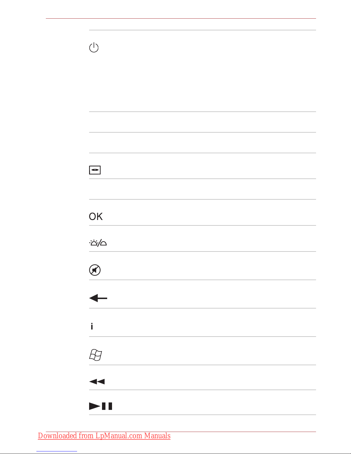
User’s Manual 2-20
The Grand Tour
Power Starts or terminate the operating system.This
button functions like the power button of your
computer. By default, the Sleep mode is
equivalent to the power off state of your
computer. To change the setting, click Start J
Control panel J System and Security J
Power Options J Choose what the power
button does. The following four options are
available: Do nothig, Sleep, Hibernate and Shut
down.
Volu me + Increases the volume while viewing DVDs or
playing CDs.
Volu me - Decreases the volume while viewing DVDs or
playing CDs.
DVD menu Opens the main menu of a DVD movie, if
available.
Arrows Moves the cursor to navigate within Media
Center windows.
OK Selects the desired action or menu option. It acts
like the ENTER Key.
LED on/off Pressing this button to switch the lighting of
indicators.
Mute Turns off the computer sound.
Back Displays the previous window.
More information Provides detailed information for functions or
options on the screen.
Start Opens the Start menu.
Rewind Moves the media (video, DVD, music, and so on)
backwards.
Play/Pause Plays the selected media. This button also acts
as a pause button.
Downloaded from LpManual.com Manuals

User’s Manual 2-21
The Grand Tour
Using the remote controller
Some computers include a remote control unit, which allows you to control
some of your computer’s functions from a distance.
Operational range of the remote controller
Point the remote controller at your computer and press a button. The
operational angle and distance are described below.
Fast forward Moves the media (video, DVD, music, and so on)
forwards.
Replay Moves media backward (seven seconds for
videos, one music track or one DVD chapter at a
time).
Stop Stops the currently playing media.
Skip Moves media forward (30 seconds for videos,
one music track or one DVD chapter at a time).
■ The remote controller is designed specifically for this computer.
■ Some application programs may not support remote control functions.
Distance Within 5 meters from the infrared receiver
window.
Angle Within approximately 30 degrees horizontal to
and 15 degrees vertical to the infrared receiver
window.
Downloaded from LpManual.com Manuals

User’s Manual 2-22
The Grand Tour
Operational range of the remote controller
TO
SH
IB
A
S
a
telli
te
1
2
30˚
30˚
15˚
5M
1. Infrared Receiver Window
2. Remote Controller
Even if within the effective scope as described above, the remote controller
may malfunction or not work correctly in the following cases.
■ When an obstacle stands between the infrared receiver window of your
computer and the remote controller.
■ When direct sunlight or strong fluorescent light strikes the infrared
receiver window.
■ When the infrared receiver window or the infrared emission part of the
remote controller is dirty.
■ When other computers which use an infrared remote controller are
used near to your computer.
■ When a low battery condition is present.
Downloaded from LpManual.com Manuals

User’s Manual 2-23
The Grand Tour
Installing/Removing batteries
Be sure to install the provided CR2016 type batteries before using the
remote controller. The procedures for installing and removing the batteries
vary depending on the type of the remote controller. Check the type and
then install or remove the batteries as instructed.
Type of battery that can be used for the remote controller
When the provided batteries run down, please replace them with CR2016
type batteries. Other types of batteries should not be used.
Store the battery for the remote controller beyond the reach of children.
If a child swallows a battery, this might result in choking. If this happens,
seek medical attention immediately.
Observe the following precautions when using the battery of the remote
controller.
■ Do not use batteries other than those specified.
■ Ensure that you insert the batteries with their polarities correctly
aligned (+ or -).
■ Do not recharge, heat, disassemble or short the battery, or put it into a
fire or flame.
■ Do not use a battery whose “recommended expiration date” has been
reached, or which is completely discharged.
■ Do not use different types of batteries or old and new batteries at the
same time.
■ Do not carry the battery together with metal necklaces, hairpins or
other metal accessories.
■ When storing or disposing of used batteries, make sure to put some
insulation tape on their terminals (+ and -) to avoid short-circuits.
If these precautions are not followed, heating, fluid leakage or explosion
may occur. This may cause burns or personal injury. If battery fluid gets on
your skin or clothes, wash immediately with clean water. If battery fluid
gets in your eyes, immediately rinse your eyes with clean water and see a
doctor. Do not touch the battery fluid on instruments or devices with bare
hands. Wipe off with a cloth or paper towel.
Downloaded from LpManual.com Manuals

User’s Manual 2-24
The Grand Tour
Installing the batteries
1. Open the battery cover on the back side of the remote controller.
Opening the battery cover
2. Be sure to place the batteries with correct polarities. Press the battery
down to the stopper then push it forward to fit into the battery case.
Inserting the batteries
3. Close the battery cover. Press gently until it clicks into place.
Closing the battery cover
Replacing the batteries
When the batteries in the remote controller reach the end of their life, the
remote controller may not operate correctly or work only within a short
distance from your computer. In this instance, you should purchase new
batteries and replace the discharged ones.
1
1. Battery Cover
1
2
1. Stopper
2. Battery
Downloaded from LpManual.com Manuals

User’s Manual 2-25
The Grand Tour
Slim size remote controller
1. Open the battery cover on the back side of the remote controller.
2. Hold down the stopper and slide the battery out of battery case.
Removing the batteries
3. Insert the battery in place. Be sure to place the batteries with correct
polarities. Press the battery down to the stopper then push it forward to
fit into the battery case.
4. Close the battery cover. Press gently until it clicks into place.
Placing the slim size remote controller
Inserting a slim size remote controller
To insert the slim size remote controller, follow the steps below.
1. Make sure the ExpressCard slot is empty.
2. Set the front side upward and insert the slim size remote controller.
Inserting the slim size remote controller
3. Press gently to ensure a firm connection.
Removing a slim size remote controller
To remove the slim size remote controller, follow the steps below.
1. Press on the slim size remote controller gently to release it.
2. Grasp the slim size remote controller and pull it out from the slot.
21
1. Stopper
2. Battery
Satellite
1
1. Slim size remote controller
Downloaded from LpManual.com Manuals

User’s Manual 3-1
Getting Started
Chapter 3
Getting Started
This chapter provides basic information to get you started using your
computer. It covers the following topics:
■ Installing the battery pack
■ Connecting the AC adaptor
■ Opening the display
■ Turning on the power
■ Windows setup
■ Turning off the power
■ Restarting the computer
■ System Recovery Options
■ Restoring the preinstalled software from the Recovery HDD
■ Restoring the preinstalled software from Recovery Media
■ All users should be sure to read the section Starting up for the first time.
■ Be sure to read the enclosed Instruction Manual for Safety and Comfort
for information on the safe and proper use of this computer. It is
intended to help you be more comfortable and productive while using a
notebook computer. By following the recommendations in it you may
reduce your chance of developing a painful or disabling injury to your
hand, arms, shoulders or neck.
■ Use an anti-virus software and update it regularly.
■ Never format storage media without checking its content - formatting
destroys all stored data.
■ It is a good idea to periodically back up the internal hard disk drive or
other main storage device to external media. General storage media is
not durable or stable over long periods of time and under certain
conditions may result in data loss.
■ Before you install a device or application, save any data in memory to
the hard disk drive or other storage media. Failure to do so may result
in the loss of data.
Downloaded from LpManual.com Manuals

User’s Manual 3-2
Getting Started
Connecting the AC adaptor
Attach the AC adaptor when you need to charge the battery or you want to
operate from AC power. It is also the fastest way to get started, because
the battery pack will need to be charged before you can operate from
battery power.
The AC adaptor can be connected to any power source supplying from 100
to 240 volts and 50 or 60 hertz. For details on using the AC adaptor to
charge the battery pack, refer to Chapter 6, Power and Power-Up Modes.
■ Always use the TOSHIBA AC adaptor that was included with your
computer or use AC adaptors specified by TOSHIBA to avoid any risk
of fire or other damage to the computer. Use of an incompatible AC
adaptor could cause fire or damage to the computer possibly resulting
in serious injury. TOSHIBA assumes no liability for any damage caused
by use of an incompatible adaptor.
■ Never plug the AC adaptor into a power source that does not
correspond to both the voltage and the frequency specified on the
regulatory label of the unit. Failure to do so could result in a fire or
electric shock, possibly resulting in serious injury.
■ Always use or purchase power cables that comply with the legal
voltage and frequency specifications and requirements in the country of
use. Failure to do so could result in a fire or electric shock, possibly
resulting in serious injury.
■ The supplied power cord conforms to safety rules and regulations in
the region from which the product is purchased and should not be used
outside this region. For use in other regions, please buy power cords
that conform to safety rules and regulations in that particular region.
■ Do not use a 3-pin to 2-pin conversion plug.
■ When you connect the AC adaptor to the computer, always follow the
steps in the exact order as described in the User’s Manual. Connecting
the power cable to a live electrical outlet should be the last step
otherwise the adaptor DC output plug could hold an electrical charge
and cause an electrical shock or minor bodily injury when touched. As
a general safety precaution, avoid touching any metal parts.
■ Never place your computer or AC adaptor on a wooden surface,
furniture, or any other surface that could be marred by exposure to heat
since the computer base and AC adaptor's surface increase in
temperature during normal use.
■ Always place your computer or AC adaptor on a flat and hard surface
that is resistant to heat damage. Refer to the enclosed Instruction
Manual for Safety and Comfort for detailed precautions and handling
instructions.
Downloaded from LpManual.com Manuals

User’s Manual 3-3
Getting Started
1. Connect the power cord to the AC adaptor.
Connecting the power cord to the AC adaptor
2. Connect the AC adaptor's DC output plug to the DC IN 19V jack on the
right of the computer.
Connecting the adaptor to the computer
3. Plug the power cord into a live wall outlet.
Either a 2-pin or 3-pin adaptor/cord will be included with the computer
depending on the model.
Downloaded from LpManual.com Manuals

User’s Manual 3-4
Getting Started
Opening the display
The display panel can be rotated in a wide range of angles for optimal
viewing.
1. Lift the panel up and adjust it to the best viewing angle for you.
Opening the display
Use reasonable care when opening and closing the display panel. Opening
it vigorously or slamming it shut could damage the computer.
■ When opening the panel, please be careful not to force it beyond the
point where it moves easily.
■ Be careful not to open the display panel too far as this could put stress
on the display panel’s hinges and cause damage.
■ Do not press or push on the display panel.
■ Do not lift the computer by the display panel.
■ Do not close the display panel with pens or any other objects left in
between the display panel and the keyboard.
■ When opening or closing the display panel, place one hand on the
palm rest to hold the computer in place and use the other hand to
slowly open or close the display panel (Do not use excessive force
when opening or closing the display panel).
Downloaded from LpManual.com Manuals

User’s Manual 3-5
Getting Started
Turning on the power
This section describes how to turn on the power.
Press and hold the computer's power button for two or three seconds.
Turning on the power
Windows setup
When you first turn on the power, the computer's initial screen is the
Microsoft® Windows Startup Screen Logo.
Follow the on-screen directions.
After you turn on the power for the first time, do not turn it off until you have
set up the operating system. Refer to the section Windows setup.
TO
S
H
IBA
S
a
tellite
TOSHIBA
Be sure to read the Windows End User License Agreement display
carefully.
Downloaded from LpManual.com Manuals

User’s Manual 3-6
Getting Started
Turning off the power
The power can be turned off in one of the following modes: Shut down
(Boot), Hibernation or Sleep Mode.
Shut Down mode (Boot mode)
When you turn off the power in Shut Down mode no data is saved and the
computer will boot to the operating system’s main screen.
1. If you have entered data, save it to the hard disk.
2. Make sure all disk (disc) activity has stopped, then remove the CD/
DVDs.
3. Click then click the Shut down button . From the drop
down menu, choose Shut Down.
4. Turn off the power to any peripheral devices.
Sleep Mode
If you have to interrupt your work, you can turn off the power without exiting
from your software. Data is maintained in the computer's main memory.
When you turn on the power again, you can continue working right where
you left off.
■ Make sure the Disk LED and ODD indicator are off. If you turn off the
power while a disk (disc) is being accessed, you can lose data or
damage the disk (disc).
■ Never turn off the power while an application is running. Doing so could
cause loss of data.
■ Never turn off the power, disconnect an external storage device or
remove storage media during data read/write. Doing so can cause data
loss.
Do not turn the computer or devices back on immediately. Wait a moment
to let all capacitors fully discharge.
When you have to turn off your computer aboard an aircraft or in places
where electronic devices are regulated or controlled, always completely
shut down the computer. This includes turning off any wireless
communication switches or devices, and canceling settings that reactivate
the computer automatically, such as a timer recording function. Failure to
completely shut down the computer in this way could allow the operating
system to reactivate and run pre-programmed tasks or preserve unsaved
data, which could interfere with aviation or other systems, possibly causing
serious injury.
Downloaded from LpManual.com Manuals

User’s Manual 3-7
Getting Started
Benefits of Sleep Mode
The Sleep Mode feature provides the following benefits:
■ Restores the previous working environment more rapidly than does
Hibernation Mode.
■ Saves power by shutting down the system when the computer receives
no input or hardware access for the duration set by the System Sleep
Mode feature.
■ You can use the panel power off feature.
Entering Sleep Mode
You can enter Sleep Mode in one of three ways:
■ Click the computer's power button.
Please note that this feature must be enabled within Power Options (to
access it, click Æ Control Panel Æ System and Security Æ
Power Options).
■ Click Start then click the arrow button located in the Shut down
button , and select Sleep from the menu.
■ Close the display panel. This feature must be enabled. Please refer to
Power Options (to access it, click Æ Control Panel Æ System and
Security Æ Power Options).
When you turn the power back on, you can continue where you left when
you shut down the computer.
■ When the AC adaptor is connected, the computer will go into Sleep
Mode according to the settings in Power Options .
■ To restore operation from Sleep Mode, press the power button or press
any key. The latter action works only if Wake-up on Keyboard is
enabled in HW Setup.
■ If the computer automatically enters Sleep Mode while a network
application is active, the application might not be restored when the
computer wakes up from Sleep Mode.
■ To prevent the computer from automatically entering Sleep Mode,
disable Sleep Mode in Power Options. However, this action will nullify
the computer's Energy Star compliance.
■ Before entering Sleep Mode, be sure to save your data.
■ Do not install or remove a memory module while the computer is in
Sleep Mode. The computer or the module could be damaged.
■ Do not remove the battery pack while the computer is in Sleep Mode
(unless the computer is connected to an AC power source). Data in
memory will be lost.
You can also enable Sleep Mode by pressing Fn + F3. Refer to Chapter 5,
The Keyboard, for details.
Downloaded from LpManual.com Manuals

User’s Manual 3-8
Getting Started
Sleep Mode limitations
Sleep Mode will not function under the following conditions:
■ Power is turned back on immediately after shutting down.
■ Memory circuits are exposed to static electricity or electrical noise.
Hibernation Mode
The hibernation feature saves the contents of memory to the hard disk
when the computer is turned off. The next time the computer is turned on,
the previous state is restored. The hibernation feature does not save the
status of peripheral devices.
Benefits of Hibernation Mode
The Hibernation Mode feature provides the following benefits:
■ Saves data to the hard disk when the computer automatically shuts
down because of a low battery.
■ You can return to your previous working environment immediately when
you turn on the computer.
■ Saves power by shutting down the system when the computer receives
no input or hardware access for the duration set by the system
hibernate feature.
■ You can use the panel power off feature.
Starting Hibernation Mode
To enter Hibernation Mode, follow the steps below.
1. Click .
2. Click the arrow icon located in the Shut down button .
3. From the drop down menu, select Hibernate.
■ When the computer is shut down to Sleep Mode, the power indicator
flashes orange.
■ If you are operating the computer on battery power, you can lengthen
the operating time by turning it off to Hibernation Mode, as Sleep Mode
consumes more power.
■ Save your data. While entering Hibernation Mode, the computer saves
the contents of memory to the HDD. However, as a safety precaution, it
is best to save your data manually.
■ Data will be lost if you remove the battery or disconnect the AC adaptor
before the save is completed. Wait for the disk indicator to go out.
■ Do not install or remove a memory module while the computer is in
Hibernation Mode. Data will be lost.
You can also enable Hibernation Mode by pressing Fn + F4. Refer to
Chapter 5, The Keyboard, for details.
Downloaded from LpManual.com Manuals

User’s Manual 3-9
Getting Started
Automatic Hibernation Mode
The computer will enter Hibernation mode automatically when you press
the power button or close the Display Screen. First, however, make the
appropriate settings according to the steps below.
1. Open the Control Panel.
2. Open System and Security and open Power Options.
3. Select Choose what the power button does.
4. Enable the desired Hibernation settings for When I press the power
button and When I close the lid.
5. Click the Save changes button.
Data saving in Hibernation Mode
When you turn off the power in Hibernation Mode, the computer takes a
moment to save current memory data to the hard disk. During this time, the
Disk LED will light up.
After you turn off the computer and memory is saved to the hard disk, turn
off the power to any peripheral devices.
Restarting the computer
Certain conditions require that you reset the system. For example, if:
■ You change certain computer settings.
■ An error occurs and the computer does not respond to your keyboard
commands.
There are three ways to reset the computer system:
■ Click then click the arrow icon located in the Shut down button
, and select Restart from drop down menu.
■ Press Ctrl + Alt + Del to display the menu window, then select Restart
from the Shut down options.
■ Press the power button and hold it down for five seconds. Once the
computer has turned itself off, wait between ten and fifteen seconds
before turning it on again with the power button.
System Recovery Options
About 1.5GB hidden partition is allocated on the hard drive for the System
Recovery Options.
Do not turn the computer or devices back on immediately. Wait a moment
to let all capacitors fully discharge.
The System Recovery Options feature will be unusable if this partition is
deleted.
Downloaded from LpManual.com Manuals

User’s Manual 3-10
Getting Started
System Recovery Options
The System Recovery Options feature is installed on the hard disk when
shipped from the factory. The System Recovery Options menu includes
some tools to repair startup problems, run diagnostics or restore the
system.
You can see the more information about “Startup Repair” in “Windows Help
and Support” content.
The System Recovery Options can also be run manually to repair
problems.
The procedure is as follows. Follow the on-screen instructions.
1. Turn off the computer.
2. While holding the F8 key, turn the computer on. The Advanced Boot
Options menu will be displayed.
3. Use the arrow keys to select Repair Your Computer and press Enter.
4. Follow the on-screen instructions.
Create Optical Recovery Discs
A recovery image of your computer is stored on the hard disk. You may use
this image to create DVD recovery discs using the following steps:
1. Select DVD media.
2. The application will allow you to choose a type of media to create
recovery DVD including: DVD-R, DVD-RW, DVD+R and DVD+RW.
3. Turn on your computer to open Windows® 7.
4. Insert the (first) blank media into the tray of the Optical Drive.
5. Double-click the Recovery Media Creator icon on your desktop, or
select the application from Start menu.
6. After TOSHIBA Recovery Media Creator starts, select the type of media
and the title you wish to copy to the media then click the Create button.
The Windows Complete PC Backup feature can be used on all Windows® 7
editions.
Some media may not be compatible with the Optical Drive of your
computer. Please verify your Optical Drive supports the blank media you
choose.
Downloaded from LpManual.com Manuals

User’s Manual 3-11
Getting Started
Restoring the preinstalled software from the
Recovery HDD
Part of the space on the hard disk drive is reserved as recovery partition for
restoring the pre-installed software from the hard disk drive.
When re-setting up your hard disk, do not change, delete or add partitions
in a manner other than specified in the manual. Otherwise, space for
software may be destroyed.
In addition, if you use a third-party partitioning program to reconfigure
partitions on your hard disk, it may become impossible to re-setup your
computer.
1. Turn off your computer.
2. Hold down the 0 (zero) key on the keyboard and turn on your computer.
3. When “TOSHIBA Leading Innovation >>>” appears, release the 0
(zero) key on the keyboard. A menu appears.
4. Follow the on-screen instructions.
■ You can not use System Recovery Options if restoring the pre-installed
software without System Recovery Options.
■ When you reinstall the Windows operating system, the hard disk will be
reformatted and all data will be lost.
Downloaded from LpManual.com Manuals

User’s Manual 3-12
Getting Started
Restoring the preinstalled software from Recovery
Media
If the preinstalled files are damaged, use the Recovery Media you created,
or HDD recovery to restore them. To restore the operating system and all
preinstalled software, follow the steps below.
1. Load the Recovery Media in the optical media drive and turn off the
computer's power.
2. Hold down the F12 key and turn on the power. When TOSHIBA
Leading Innovation >>> appears, release the F12 key.
3. Use the upper or lower cursor key to select the CD/DVD in the display
menu. A menu appears. For details, refer to the Boot Priority section in
Chapter 7, HW Setup.
4. Follow the on-screen instructions.
When you reinstall the Windows operating system, the hard disk will be
reformatted and all data will be lost.
If you have removed pre-installed drivers/ utilities or when installing, you
can setup drivers/ utilities from the following folder.
C:\Program Files\TOSHIBA\TOSAPINS\***
Downloaded from LpManual.com Manuals

User’s Manual 4-1
Operating Basics
Chapter 4
Operating Basics
This chapter gives information on basic operations including using the
TouchPad, optical media drives, sound system, modem, the wireless LAN
and LAN. It also provides tips on caring for your computer.
Using the TouchPad
To use the TouchPad, simply touch and move your finger tip across it in the
direction you want the on-screen pointer to go.
TouchPad and TouchPad control buttons
TO
SHIB
A
Sate
llite
1
2
1. TouchPad
2. TouchPad control buttons
Downloaded from LpManual.com Manuals

User’s Manual 4-2
Operating Basics
Two buttons below the keyboard are used like the buttons on a mouse
pointer. Press the left button to select a menu item or to manipulate text or
graphics designated by the pointer. Press the right button to display a menu
or other function depending on the software you are using.
For some functions, you can tap the TouchPad instead of pressing a control
button.
Touch Pad Gesture
There are four convenient gestures that make users operate the system
easier and faster.
ChiralMotion
You can scroll vertically and horizontally. To enable these features, select
the Enable vertical scrolling and Enable horizontal scrolling check
boxes.
Click on the window or item you wish to scroll and slide your finger upwards
or downwards along the right edge of the TouchPad to scroll vertically. Slide
your finger to the left or right along the lower edge of the TouchPad to scroll
horizontally.
If scrolling does not respond, ensure that the appropriate check box is
selected and that the window or item on which you have clicked is
scrollable. If you still have problems, check your Scrolling Region settings.
Pinch Zoom (Pinch)
The Pinch Zoom gesture delivers zooming functionality in many
applications. You can use the Pinch Zoom gesture to perform the same
functions that a scroll wheel performs on standard Windows applications
that support CTRL-SCROLL WHEEL zoom functionality.
To enable this feature, select the Enable Pinch Zoom check box.
Do not press on the TouchPad too hard or press a sharp object such as a
ball point pen against the TouchPad. The TouchPad could be damaged.
Click: Tap the TouchPad once
Double-click: Tap the TouchPad twice
Drag and drop:
1. Hold down the left control button and move the cursor to drag the item
you want to move.
2. Lift your finger to drop the item where you want it.
Scroll:
Vertical: Move your finger up or down the right edge of the TouchPad.
Horizontal: Move your finger left or right along the bottom edge of the
TouchPad.
Downloaded from LpManual.com Manuals

User’s Manual 4-3
Operating Basics
To use a Pinch Zoom gesture:
1. Place two fingers down on the TouchPad surface.
2. Slide the fingers further apart to zoom in or slide the fingers closer
together to zoom out. For the best zooming experience, use the tips of
your fingers.
Rotating (ChiralRotate)
The Rotating features provide convenient gestures for rotating photos and
other objects.
Momentum
The Momentum feature delivers smooth, fast, trackball-like mouse
movement. One quick flick of the finger on the TouchPad surface can move
the cursor across the entire computer screen. Momentum reduces the
repetitive motion and fatigue associated with moving the cursor long
distances, while providing a smooth and natural feel similar to using a
trackball. Momentum is ideal for Real Time Strategy (RTS) games, First
Person Shooter (FPS) games, and Role Playing Games (RPG).
The two buttons below the Touch Pad are used like the buttons on a
standard mouse - press the left button to select a menu item or to
manipulate text or graphics designated by the pointer, and press the right
button to display a menu or other function depending on the software you
are using.
Using the fingerprint sensor
This product has a fingerprint utility installed for the purpose of enrolling
and recognizing fingerprints. By enrolling the ID and password to the
fingerprint authentication device, it is no longer necessary to input the
password from the keyboard. Just by swiping the finger against the
fingerprint sensor, the following functions will be enabled:
■ Logon to Windows and access a security-enabled homepage through
IE (Internet Explorer).
■ Files and folders can be encrypted/decrypted and third party access to
them prevented.
■ Disable the password-protected screen-saver when returning from
power-saving (Sleep) mode.
■ Pre-OS feature and Single Sign-On feature.
■ Authentication of the User Password and Hard Disk Password when
booting up the computer.
To “swipe” refers to the action of reading a fingerprint using the fingerprint
sensor.
Downloaded from LpManual.com Manuals

User’s Manual 4-4
Operating Basics
How to swipe the finger
Using the following steps when swiping fingers for fingerprint registration or
authentication will help to minimize authentication failures:
1. Align the first joint of the finger to the center of the sensor.
2. While lightly touching the sensor, swipe the finger towards you until the
sensor surface becomes visible.
3. Ensure the center of the fingerprint is on the sensor when swiping the
finger.
Slide the finger over the recognition sensor
■ Avoid swiping with the finger stiff or pressing too hard:
Fingerprint reading may fail if the center of the fingerprint is not
touching on the sensor, or when finger is swiped while pressing hard.
Make sure that the center of the fingerprint is touching the sensor
before swiping.
■ Confirm the center of the fingerprint whirl before swiping:
The thumb’s fingerprint has a bigger whirl, which is prone to
misalignment and distortions. This will cause difficulty in registration
and a drop in the authentication success rate. Always confirm the
center of the fingerprint whirl so that it is swiped along the centerline of
the sensor.
■ When fingerprint reading is not successful:
There is a possibility of authentication failure if the finger is swiped too
quickly or too slowly. Follow the onscreen instructions to adjust the
speed of the swipe.
Downloaded from LpManual.com Manuals

User’s Manual 4-5
Operating Basics
Points to note about the fingerprint sensor
Failure to follow these guidelines might result in (1) damage to the sensor
or cause sensor failure, (2) fingerprint recognition problems, or lower
fingerprint rec-ognition success rate.
■ Do not scratch or poke the sensor with your nails or any hard or sharp
objects.
■ Do not press too hard on the sensor.
■ Do not touch the sensor with a wet finger or any wet objects. Keep the
sensor surface dry and free of water vapor.
■ Do not touch the sensor with a soiled finger. Minute foreign particles on
a soiled or dirty finger may scratch the sensor.
■ Do not paste stickers or write on the sensor.
■ Do not touch the sensor with a finger or any object with built-up static
electricity.
Observe the following before you place your finger on the sensor.
■ Wash and dry your hands thoroughly.
■ Remove static electricity from your fingers by touching any metal
surface. Static electricity is a common cause of sensor failures,
especially when the weather is dry.
■ Clean the sensor with a lint-free cloth. Do not use detergent to clean the
sensor.
■ Avoid the following finger conditions for enrollment or recognition as
they may result in fingerprint enrollment errors or a drop in the
fingerprint recognition success rate.
■ Soaked or swollen finger (e.g. after taking bath)
■ Injured finger
■ Wet finger
■ Soiled or oily finger
■ Extremely dry skin condition
Observe the following to improve the fingerprint recognition success rate.
■ Enroll two or more fingers.
■ Enroll additional fingers if recognition failure occurs often with enrolled
fingers.
■ Check your finger condition. Changed conditions, such as injured,
rough, extremely dry, wet, soiled, dirty, oily, soaked and swollen fingers,
may lower the recognition success rate. Also, if the fingerprint is worn
down or the finger becomes thinner or fatter, the recognition success
rate may be lowered.
Downloaded from LpManual.com Manuals

User’s Manual 4-6
Operating Basics
■ The fingerprint for each finger is different and unique. Please ensure
that only the registered or enrolled fingerprint or fingerprints are used
for identification.
■ Check sliding position and speed.
■ You can enroll up to 30~34 fingerprint data entries.
■ Fingerprint data is stored into the nonvolatile memory in the fingerprint
sensor. Before you dispose of the computer, it is recommended that you
delete the fingerprint data with the Delete menu of Fingerprint Software
Management.
How to delete the fingerprint data
Saved fingerprint data is stored in the Non-volatile memory inside the
fingerprint sensor. If you hand over the PC to others, or dispose of it, the
following operations are recommended.
1. Click Start Æ All Programs Æ TrueSuite Access Manager. The
TrueSuite Access Manager Fingerprint Software screen is displayed.
2. Enter your Windows Password and click Next to enter the Control
Center, or swipe your enrolled finger to enter the Control Center.
3. Click Delete All Fingerprints.
Fingerprint sensor limitations
■ The fingerprint sensor compares and analyzes the unique
characteristics in a fingerprint.
■ A warning message will be displayed when recognition is abnormal or
recognition is not successful within a fixed duration.
■ The recognition success rate may differ from user to user.
■ Toshiba does not guarantee that this fingerprint recognition technology
will be error-free.
■ Toshiba does not guarantee that the fingerprint sensor will recognize
the enrolled user or accurately screen out unauthorized users at all
times.Toshiba is not liable for any failure or damage that might arise out
of the use of this fingerprint recognition software or utility.
Downloaded from LpManual.com Manuals

User’s Manual 4-7
Operating Basics
Points to note about the fingerprint utility
■ If the Windows file encryption function EFS (Encryption File System) is
used to encrypt a file, the file cannot be further encrypted using the
encryption function of this software.
■ You can back up the fingerprint data or the information registered to
Password Bank.
■ Please use Import/Export menu on Fingerprint Software Management.
■ Please also refer to the fingerprint utility Help file for more information.
You can start it using the following methods:
■ Click Start Æ All Programs Æ TrueSuite Access Manager Æ
Document.
■ Click Start Æ All Programs Æ TrueSuite Access Manager. The
main screen is displayed. Click Help in the upper right corner of the
screen.
Set up procedure
Please perform the following procedure when first using fingerprint
authentication.
Fingerprint registration
Enroll the required authentication data using the Fingerprints Enrollment
Wizard.
1. Click Start Æ All Programs Æ TrueSuite Access Manager, or double
click the icon in the Task Bar. The Enter Windows Password screen is
displayed.
2. Enter a password into the Enter Windows Password field and click
Next. The Control Center screen is displayed.
3. Click the non-enrolled finger icon above the finger. The Fingerprint
Enrollment screen is displayed.
4. Confirm the message and click Next. The Scanning Practice screen is
displayed.
5. You can practice swiping your finger. When you have finished practicing
swiping your finger, click Next. The Fingerprint Image Capture screen is
displayed.
6. Follow the onscreen instructions and use the same finger you have
selected under the Control Center to swipe your finger with good
images three times for the fingerprint template to be created.
7. In case of finger injury or authentication failure, it is recommended that
you enroll another fingerprint. The following message will be displayed:
[We recommended enrolling at least two fingerprint
images.] Click OK and repeat steps 3, 4, 5 and 6 with another finger.
■ The fingerprint authentication uses the same Windows logon ID and
password. If the Windows logon password has not been setup, please
do so before registration.
■ Up to 30~34 fingerprint patterns can be registered.
Downloaded from LpManual.com Manuals

User’s Manual 4-8
Operating Basics
Windows logon via fingerprint authentication
In place of the usual Windows logon by ID and password, fingerprint
authentication also allows logon to Windows.
This is especially useful when many users are using the computer, as user
selection can be skipped.
Fingerprint authentication procedure
1. Start up the computer.
2. The Logon Authorization screen is displayed. Choose any of the
enrolled fingers and swipe the fingerprint on the sensor. If
authentication is successful, the user will be logged on to Windows.
Fingerprint system boot authentication
General
The fingerprint authentication system can be used to replace the keyboard
based User Password authentication system when booting up.
If you prefer to use the keyboard-based system instead of the fingerprint
authentication system for password authentication when booting up, press
the BACK SPACE key when the Fingerprint System Boot Authentication
screen is displayed. This will switch the password input screen to the
keyboard-based one.
■ If the fingerprint authentication fails, please logon using the Windows
logon password.
■ Please logon using the Windows logon password if the fingerprint
authentication fails for five times. To logon using the Windows logon
password, enter the Windows logon password at the [Welcome]
screen.
■ A warning message will be displayed when authentication is abnormal
or authentication is not successful within a fixed duration.
■ It is necessary to register the User Password before using the
fingerprint Pre-OS feature and its extended function, the fingerprint
Single Sign-On feature. Please use TOSHIBA HW Setup to register the
User Password.
■ If you fail fingerprint authentication more than five times, you must
enter the User Password or Supervisor Password manually to start the
computer.
■ When swiping, please do it slowly and at a constant speed. If this does
not improve the authentication rate, please adjust the speed.
■ If there are any changes in the environment or settings related to
authorization, you will be required to provide authorization information
such as a User Password and HDD password.
Downloaded from LpManual.com Manuals

User’s Manual 4-9
Operating Basics
How to enable fingerprint system boot authentication
settings
It is necessary to first enroll your fingerprint with the TrueSuite Access
Manager application prior to enabling and configuring the fingerprint
Pre-OS feature.
Check that your fingerprint is enrolled before configuring the settings.
1. Swipe your finger across the fingerprint sensor, or enter the Windows
password and click Next.
2. Click settings. The Administrator Settings screen is displayed.
3. Place a checkmark in “Enable Pre-OS Fingerprint Authentication” and
click OK.
The modified configuration for fingerprint Pre-OS feature becomes effective
the next time the system boots up.
Fingerprint Single Sign-On feature
General
This is a feature that allows the user to complete the authentication for both
the User Password (and optionally, the HDD user and Supervisor
passwords) and logging on to Windows using only one fingerprint
authentication when booting up. It is necessary to register the User
Password and Windows Logon password before using the fingerprint PreOS feature and this fingerprint Single Sign-On feature. Please use
TOSHIBA HW Setup to register your User Password.
Only one fingerprint authentication is required to replace the User
Password (and, if selected, the HDD user and Supervisor passwords) and
Windows Logon password.
How to enable fingerprint Single Sign-On feature
It is necessary to first enroll your fingerprint with the TrueSuite Access
Manager application prior to enabling and configuring the fingerprint Single
Sign-On feature. Check that the fingerprint is enrolled before configuring
the settings.
1. Swipe your finger across the fingerprint sensor, or enter the Windows
password and click Next.
2. Click settings. The Administrator Settings screen is displayed.
3. Place a checkmark in “Enable Pre-OS Fingerprint Authentication”.
4. Place a checkmark in “Enable Single Sign-On Fingerprint
Authentication” and click OK.
The modified configuration for the fingerprint Single Sign-On feature
becomes effective the next time the system boots up.
Downloaded from LpManual.com Manuals

User’s Manual 4-10
Operating Basics
Fingerprint utility limitations
TOSHIBA does not guarantee that the fingerprint utility technology will be
completely secure or error-free. TOSHIBA does not guarantee that the
fingerprint utility will accurately screen out unauthorized users at all times.
TOSHIBA is not liable for any failure or damage that might arise out of the
use of the fingerprint software or utility.
USB Sleep and Charge function
Your computer can supply USB bus power (DCSV) to the USB port even
when the power of the computer is turned OFF. "Power OFF" includes
Sleep Mode, Hibernation Mode or shutdown state.
This function can only be used for ports that support the USB Sleep and
Charge function (hereinafter called "compatible ports").
Compatible ports are USB ports that have the ( ) symbol.
You can use the "USB Sleep and Charge function" to charge certain USB-
compatible external devices such as mobile phones or portable digital
music players.
However, the "USB Sleep and Charge function" may not work with certain
external devices even if they are compliant with the USB specification. In
those cases, turn ON the power of the computer to charge the device.
■ The "USB Sleep and Charge function" only works for compatible ports.
This function is disabled in the default setting.
■ When "USB Sleep and Charge function" is set to [Enabled], USB bus
power (DC5V) will be supplied to compatible ports even when the
power of the computer is turned OFF.
USB bus power (DC5V) is similarly supplied to the external devices
which are connected to the compatible ports. However, some external
devices cannot be charged solely by supplying USB bus power
(DC5V).
As for the specifications of the external devices, please contact the
device manufacturer or check the specifications of the external devices
thoroughly before use.
■ Using the USB sleep and charge function to charge external devices
will take longer than charging the devices with their own chargers.
■ If USB Sleep and Charge function is enabled, the computer’s battery
will discharge during hibernation or when the computer is turned off. It
is recommended that you connect the AC adaptor to the computer
when enabling the USB Sleep and Charge function.
■ External devices connected to the USB bus power (DC5V) function that
interfaces with the power ON/OFF of the computer may always be in
an operational state.
■ When there is a current overflow of the external devices connected to
the compatible ports, USB bus power (DC5V) supply may be stopped
for safety reasons.
Downloaded from LpManual.com Manuals

User’s Manual 4-11
Operating Basics
Starting the USB Sleep and Charge Utility
To start the utility, click Start Æ All Programs Æ TOSHIBA Æ Utilities Æ
USB Sleep and Charge.
Enabling USB Sleep and Charge
This utility can be used to enable and disable the USB Sleep and Charge
function. Check the "USB Sleep and Charge" checkbox. In the default
state, this function is disabled. Power supply mode settings
There are several USB Sleep and Charge function modes. "Mode4/Typical
Mode" should normally be used. Set one of the other modes (try from
"Mode3/Alternate Mode")
*1
if the charge function cannot be used in "Mode
4 (Default)". This function may not be able to be used with some connected
external devices even if the appropriate mode is selected. In this situation,
uncheck the "USB Sleep and Charge" checkbox and stop using this
function.
*1 Some mode may not be displayed in the list.
Battery Settings
This utility can be used to specify the lower limit of remaining battery life for
USB Sleep and Charge. Move the slider bar to specify the lower limit. If the
remaining battery life falls before the setting, the "USB Sleep and Charge"
function will be stopped. Unchecking the "Enable under Battery Mode"
checkbox sets the utility to only charge when the AC adaptor is connected.
Metal paper clips or hair pins/clips will generate heat if they come into
contact with USB ports. Do not allow USB ports to come into contact with
metal products, such as when carrying the computer in your bag.
Downloaded from LpManual.com Manuals
 Loading...