

Toshiba Satellite P20-25 Series Maintenance Manual

Toshiba Personal Computer
Satellite P20-25 Series
Maintenance Manual
TOSHIBA CORPORATION

Copyright
© 2003 by Toshiba Corporation. All rights reserved. Under the copyright laws, this manual
cannot be reproduced in any form without the prior written permission of Toshiba. No patent
liability is assumed with respect to the use of the information contained herein.
Toshiba Personal Computer Satellite P20-25 Series Maintenance Manual
First edition June 2003
Disclaimer
The information presented in this manual has been reviewed and validated for accuracy. The
included set of instructions and descriptions are accurate for the P20 Series at the time of this
manual's production. However, succeeding computers and manuals are subject to change
without notice. Therefore, Toshiba assumes no liability for damages incurred directly or
indirectly from errors, omissions, or discrepancies between any succeeding product and this
manual.
Trademarks
IBM is a registered trademark, and OS/2 and PS/2 are trademarks of IBM Corporation.
Microsoft, MS-DOS, Windows, DirectSound and DirectMusic are registered trademarks of
Microsoft Corporation.
Intel and Pentium are registered trademarks, and SpeedStep is a trademark of Intel
Corporation.
Sound Blaster is a registered trademark of Creative Technology Ltd.
Centronics is a registered trademark of Centronics Data Computer Corporation.
Photo CD is a trademark of Eastman Kodak.
All other properties are trademarks or registered trademarks of their respective holders.
ii Satellite P20-25 Series Maintenance Manual
Preface
This maintenance manual describes how to perform hardware service maintenance for the
Toshiba Personal Computer Satellite P20 Series, referred to as the P20-25 Series in this
manual.
The procedures described in this manual are intended to help service technicians isolate
faulty Field Replaceable Units (FRUs) and replace them in the field.
SAFETY PRECAUTIONS
Four types of messages are used in this manual to bring important information to your
attention. Each of these messages will be italicized and identified as shown below.
DANGER: “Danger” indicates the existence of a hazard that could result in death or
serious bodily injury if the safety instruction is not observed.
WARNING: “Warning” indicates the existence of a hazard that could result in bodily
injury if the safety instruction is not observed.
CAUTION: “Caution” indicates the existence of a hazard that could result in property
damage if the safety instruction is not observed.
NOTE: “Note” contains general information that relates to your safe maintenance
service.
Improper repair of the computer may result in safety hazards. Toshiba requires service
technicians and authorized dealers or service providers to ensure the following safety
precautions are adhered to strictly.
Be sure to fasten screws securely with the right screwdriver. If a screw is not fully
fastened, it could come loose, creating a danger of a short circuit, which could cause
overheating, smoke or fire.
If you replace the battery pack or RTC battery, be sure to use only the same model
battery or an equivalent battery recommended by Toshiba. Installation of the wrong
battery can cause the battery to explode.
Satellite P20-25 Series Maintenance Manual iii

The manual is divided into the following parts:
Chapter 1 Hardware Overview describes the P20-25 Series system unit and each
FRU.
Chapter 2 Troubleshooting Procedures explains how to diagnose and resolve
FRU problems.
Chapter 3 Test and Diagnostics describes how to perform test and diagnostic
operations for maintenance service.
Chapter 4 Replacement Procedures describes the removal and replacement of the
FRUs.
Appendices The appendices describe the following:
Handling the LCD module
Board layout
Pin assignments
Keyboard scan/character codes
Key layout
Screw torque list
Reliability
iv Satellite P20-25 Series Maintenance Manual

Conventions
This manual uses the following formats to describe, identify, and highlight terms and
operating procedures.
Acronyms
On the first appearance and whenever necessary for clarification acronyms are enclosed in
parentheses following their definition. For example:
Read Only Memory (ROM)
Keys
Keys are used in the text to describe many operations. The key top symbol as it appears on
the keyboard is printed in boldface type.
Key operation
Some operations require you to simultaneously use two or more keys. We identify such
operations by the key top symbols separated by a plus (+) sign. For example, Ctrl + Pause
(Break) means you must hold down Ctrl and at the same time press Pause (Break). If
three keys are used, hold down the first two and at the same time press the third.
User input
Text that you are instructed to type in is shown in the boldface type below:
DISKCOPY A: B:
The display
Text generated by the computer that appears on its display is presented in the type face
below:
Format complete
System transferred
Satellite P20-25 Series Maintenance Manual v

vi Satellite P20-25 Series Maintenance Manual

Table of Contents
Chapter 1 Hardware Overview
1.1 Features ......................................................................................................................1-1
1.2 System Unit................................................................................................................ 1-5
1.3 2.5-inch Hard Disk Drive........................................................................................... 1-9
1.4 Removable Drives.................................................................................................... 1-10
1.5 Power Supply ........................................................................................................... 1-11
1.6 Batteries ...................................................................................................................1-13
Chapter 2 Troubleshooting Procedures
2.1 Troubleshooting Introduction .................................................................................... 2-1
2.2 Troubleshooting Flowchart........................................................................................ 2-2
2.3 Power Supply Troubleshooting.................................................................................. 2-7
2.4 Display Troubleshooting.......................................................................................... 2-12
2.5 FDD Troubleshooting .............................................................................................. 2-15
2.6 Keyboard Troubleshooting ...................................................................................... 2-17
2.7 External USB Devices Troubleshooting.................................................................. 2-20
2.8 TV-Out Failure Troubleshooting ............................................................................. 2-22
2.9 Printer Port Troubleshooting ................................................................................... 2-24
2.10 TouchPad Troubleshooting...................................................................................... 2-26
2.11 Speaker Troubleshooting ......................................................................................... 2-28
2.12 Optical Drive Troubleshooting ................................................................................ 2-30
2.13 Modem Troubleshooting.......................................................................................... 2-33
2.14 PCMCIA Troubleshooting....................................................................................... 2-35
2.15 IEEE 1394 Troubleshooting ....................................................................................2-37
2.16 Wireless LAN Troubleshooting............................................................................... 2-39
2.17 Bluetooth Troubleshooting ...................................................................................... 2-41
Satellite P20-25 Series Maintenance Manual vii

Chapter 3 Tests and Diagnostics
3.1 The Diagnostic Test ................................................................................................... 3-1
3.2 Executing the Diagnostic Test ................................................................................... 3-2
3.3 Config Check Test .....................................................................................................3-6
3.4 DMI Check Test......................................................................................................... 3-7
3.5 PIO Loopback Test .................................................................................................... 3-8
3.6 IEEE 1394 Test .......................................................................................................... 3-9
3.7 Speaker Audio Test.................................................................................................. 3-10
3.8 Fan ON/OFF Test .................................................................................................... 3-11
3.9 Main Battery Charge Test........................................................................................ 3-12
3.10 FDD Test.................................................................................................................. 3-13
3.11 CD-ROM Test.......................................................................................................... 3-14
3.12 Keyboard Test.......................................................................................................... 3-15
3.13 Mouse (Pad) Test ..................................................................................................... 3-18
3.14 LCD Pixels Mode Test............................................................................................. 3-20
3.15 Lid Switch Test........................................................................................................ 3-21
3.16 HDD R/W Test ........................................................................................................ 3-22
3.17 LAN Test ................................................................................................................. 3-24
3.18 RTC Test.................................................................................................................. 3-26
3.19 CD Control Button Test........................................................................................... 3-27
viii Satellite P20-25 Series Maintenance Manual

Chapter 4 Replacement Procedures
4.1 General.......................................................................................................................... 1
4.2 Battery........................................................................................................................... 7
4.3 PC Card......................................................................................................................... 9
4.4 Removable modules.................................................................................................... 12
4.5 Optical Drive............................................................................................................... 15
4.6 TV Tuner..................................................................................................................... 17
4.7 Removable HDD......................................................................................................... 19
4.8 Removable FDD ......................................................................................................... 23
4.9 Wireless LAN Unit ..................................................................................................... 25
4.10 Expansion Memory..................................................................................................... 28
4.11 Modem / Bluetooth Unit ............................................................................................. 31
4.12 CPU............................................................................................................................. 34
4.13 HDD............................................................................................................................ 38
4.14 Keyboard..................................................................................................................... 42
4.15 Top Cover ................................................................................................................... 45
4.16 Function Key Board.................................................................................................... 48
4.17 LED / Power Button Board......................................................................................... 50
4.18 TouchPad .................................................................................................................... 52
4.19 Display Assembly ....................................................................................................... 54
4.20 System Board .............................................................................................................. 58
4.21 Direct Play Button Board............................................................................................ 62
4.22 CIR Board ................................................................................................................... 64
4.23 Direct play LED board................................................................................................ 66
4.24 Audio Board................................................................................................................ 68
4.25 Speakers ...................................................................................................................... 70
4.26 Fan Set ........................................................................................................................ 72
4.27 Display Mask .............................................................................................................. 75
4.28 FL Inverter Board ....................................................................................................... 77
4.29 LCD Module ............................................................................................................... 80
Satellite P20-25 Series Maintenance Manual ix

Appendices
Appendix A Handling the LCD Module ........................................................................... A-1
Appendix B Board Layout ................................................................................................ B-1
Appendix C Pin Assignments............................................................................................ C-1
Appendix D Keyboard Scan/Character Codes .................................................................. D-1
Appendix E Key Layout.....................................................................................................E-1
Appendix F Series Screw Torque List ............................................................................... F-1
Appendix G Reliability...................................................................................................... G-1
x Satellite P20-25 Series Maintenance Manual

Chapter 1
Hardware Overview

1 Hardware Overview
1-ii Satellite P20-25 Series Maintenance Manual

1 Hardware Overview
Chapter 1 Contents
1.1 Features......................................................................................................................... 1
1.2 System Unit................................................................................................................... 5
1.3 2.5-inch Hard Disk Drive.............................................................................................. 8
1.4 Removable Drives......................................................................................................... 9
1.4.1 3.5-inch Floppy Disk Drive.............................................................................9
1.4.2 DVD-R/-RW Drive .......................................................................................10
1.4.3 DVD-ROM Drive..........................................................................................11
1.4.4 DVD Multi-Drive..........................................................................................12
1.4.5 Combo Drive.................................................................................................13
1.5 Power Supply.............................................................................................................. 14
1.6 Batteries ...................................................................................................................... 16
1.6.1 Main Battery..................................................................................................16
1.6.2 RTC battery...................................................................................................18
Satellite P20-25 Series Maintenance Manual 1-iii

1 Hardware Overview
1-iv Satellite P20-25 Series Maintenance Manual

1.1 Features 1 Hardware Overview
1.1 Features
The Satellite P20-25 Series Personal Computer uses extensive Large Scale Integration (LSI),
and Complementary Metal-Oxide Semiconductor (CMOS) technology extensively to provide
compact size, minimum weight and high reliability. This computer incorporates the
following features and benefits:
CPU
Intel Desktop P4 up to 2.4GHZ or Northwood upgradable
Chipset
• Intel DT Springdale (865 PE)
• Intel 82801 EB I/O Controller HUB5(ICH5)
• PC87591L for Keyboard Controller, Battery Management Unit and RTC
• T7L58XB for CardBus and SD Controller
• nVIDIA NV34M Graphics Controller
• Cirrus logic ALC202 for AC97 CODEC
• OZ168 for Direct CD Play Controller
• 8101L for LAN Controller
Memory
• On board with two 200-pin +2.5V SO-DIMM connectors, supporting DDR
• 256 KB/512KB L2 Cache on CPU
• External 64MB VGA DDR RAM
BIOS
• 512KB Flash ROM for system BIOS.
• Suspend to RAM/Disk.
• Password protection (System).
• Windows XP ready with PnP
• Various hot key for system control.
• Refreshable
• Complete ACPI 1.0B Function
Power
• 12 cells Li-Ion 18650 size smart battery Pack with 95Wh capacity
• 2.0 hours operation as running battery mark 2001 version 1.0/+ program
• 12 hours charging time to 100% capacity on Li-Ion Battery (System on)
• Brightness Minimum plus 3 steps
• RTC battery (Sanyo ML1220T128 3.3V/15mAH Lithium) backs up the Real
RAM cards. Maximum upgradable to 1GB by two 512MB SO-DIMM modules
Time Clock and CMOS memory
Satellite P20-25 Series Maintenance Manual 1-1

1 Hardware Overview 1.1 Features
HDD
• One 2.5", 9.5mm hard disk with capacity 30GB/40GB/60GB/80GB
• Bus Master IDE
• 9.5mm, 2.5”HDD support
• Support Ultra 100 synchronous DMA
FDD / DVD Devices
One of the following:
• 12.7mm, 1.44MB FDD device
• 5.25” 12.7mm height DVD-R/RW device
• 5.25” 12.7mm height DVD-ROM device
• 5.25” 12.7mm height DVD multi-drivedevice
• 5.25” 12.7mm height combo device
Keyboard
An easy-to-use 87-key keyboard provides a numeric keypad overlay for fast numeric
data entry or for cursor and page control. It supports software that uses a 101- or 102-
®
key enhanced keyboard. Includes one Windows
key and one Application key.
TouchPad
This pointing control device, located in the center of the keyboard palm-rest, provides
convenient control of the cursor without requiring desk space for a mouse. The
TouchPad incorporates two mouse buttons.
Display
The following types of display are available:
• 17.0-inch WXGA TFT screen, 1440×900 pixels, Response time 31ms (typ.);
Contrast ratio 350:1 (typ.); Brightness 150 Nit (typ.)
• 17.1-inch WXGA TFT screen, 1440×900 pixels, Response time 31ms (typ.);
Contrast ratio 300:1 (typ.); Brightness 160 Nit (typ.)
Optional devices
• 64MB/128MB/256MB/512MB SO-DIMM modules
• MINI PCI module(802.11b wireless LAN module)
• Modem with MDC solution module
1-2 Satellite P20-25 Series Maintenance Manual

1.1 Features 1 Hardware Overview
I/O Ports
• One 25-pin parallel port, EPP/ECP capability
• One 15-pin CRT port, supports DDC 2B
• One TV-out connector
• One MIC-in port
• One line-in port
• One headphone-out
• One 2-pin AC adapter jack
• One type III or two type II PCMCIA card bus slots
• Four 4-pin USB ports
• One RJ11/RJ45 port
• VR for volume control
• IEEE1396 (i.Link / FireWire) port
• CIR port
Universal Serial Bus (USB)
The computer comes with four USB ports that comply with Universal Host Controller
Interface (UHCI). The USB enables daisy-chain connection of up to 127 USBequipped devices. It is designed for easy configuration by a Plug-and-Play operating
system and provides hot insertion/ejection capability.
Parallel port
A 25-pin parallel port enables connection of a printer or other parallel device. The
port supports Extended Capabilities Port (ECP) conforming to IEEE-1284 and is
Enhanced Parallel Port (IEEE 1284) compliant. It features ChiProtect circuitry for
protection against damage due to printer power-on.
External monitor port
A 15-pin CRT port supporting DDC 2B enables connection of an external monitor,
which is recognized automatically by Video Electronics Standards Association
(VESA) Display Data Channel (DDC) compatible functions.
PC Card Slot
The PC Card Slot accommodates two 5mm cards (Type II) or one 10.5mm (Type III)
card and supports SRAM, OTPROM, FLASH ROM, and mask ROM memory cards
up to 64MB as well as MODEM/LAN cards, ATA cards and Card bus cards. ACPI
1.0b compliant.
Satellite P20-25 Series Maintenance Manual 1-3

1 Hardware Overview 1.1 Features
Sound system
A Cirrus logic ALC202 for AC97 codec audio subsystem offers industry leading
mixed signal technology to enhance the computer’s multimedia capability. The
sound system is equipped with stereo speakers and jacks for headphone and external
microphone.
TV-out port
This video-out mini-jack enables transfer of NTSC or PAL data (video and right/left
audio) to external devices such as a TV.
LAN port
The computer comes with an RJ-45 Local Area Network (LAN) port. The LAN port
provides connectivity for LAN.
CD/Digital Mode Button and audio/video control buttons
Unlock the control buttons by pressing the CD/Digital Mode Button for three seconds.
When unlocked, the CD or Digital LED will light on the front panel. When unlocked,
press the CD/Digital Mode Button briefly to switch between CD mode and digital
mode. CDs can be played with the computer turned off. Pressing play in digital mode
will start the computer and launch the digital music player application.
1-4 Satellite P20-25 Series Maintenance Manual

1.2 System Unit 1 Hardware Overview
1.2 System Unit
The system unit is composed of the following major components:
Processor
• Intel Desktop P4 up to 2.4GHZ or Northwood upgradable
– mPGA478 package CPU
– FSB533 Northwood CPU 2.53G/2.66G/2.8G w/o HT
– FSB533 Northwood CPU 3.06G w/HT
– FSB800 Northwood CPU 2.4G/2.6G/2.8G/3.0G/3.2G w/HT
System Logic
• Intel chipset MCH Springdale PE
• Integrated DRAM controller
• Accelerated Graphics Port (AGP) Interface
• Hub Interface to Intel ICH5
• Power Management Functions
Fixed Disk Interface
• Intel 82801 EB I/O Controller HUB5 (ICH5)
KBC/EC (Keyboard Controller/Embedded Controller)
• One PC87591 chip functions as both KBC and EC.
• KBC has the following functions:
– Scan controller to check status of keyboard matrix
– Interface controller between the keyboard scan controller and the
system
– Control of switching and simultaneous operation of the
accupoint/external PS/2 mouse and of the internal keyboard/external
PS/2 keyboard
• EC has the following functions:
– Power supply sequence control
– Thermal conditions control
– LEDs control
– Beep control
– Devices ON/OFF control
– FAN revolutions rate control
– General Input/Output port control
– Docker power supply control
– Battery capacity check
– Flash rewriting
– Detection of abnormal condition
– EC I/F
– I2C Communication
– EC access
Satellite P20-25 Series Maintenance Manual 1-5

1 Hardware Overview 1.2 System Unit
Memory
• System DRAM
• Two JEDEC standard 200-pins SO-DIMM memory support +2.5V
64/128/256MB/512MB.
• System & KB Combine ROM BIOS
• 512KB Flash ROM
Video Subsystem
• nVIDIA NV34M Graphics Controller)
• Microsoft-DX9 & OpenGL-2.0 (with NVIDIA extensions) Graphics APIs
hardware support
• 50 million triangles per second setup engine
• 1000 million pixels per second fill rate
• 256-bit 3D and 2D graphics accelerator, with full 32/64/128-bit color with 32-
bit z/stencil (24+8 bit) support
• Complete pipeline support for 128-bit color for ultimate rendering quality
• NVIDIA Accuview+ anti-aliasing technology for full Quincunx AA
capability –even for high-resolution UXGA panels
• Raw Peak memory bandwidth of 8.0 GB/second
• Supports 128-bit DDR SDRAM, driven by a twin memory channel architecture,
for maximizing memory bandwidth utilization to enhance rendering
performance while minimizing power-consumption as well.
• DirectX and S3TC texture compression support
• AGP8x (with Fast Writes & Side-band-Signaling support) - for enhanced host
interface bandwidth up-to 2.1Gbytes/second; with AGP4x, 2x support as well
• Enhanced nView+ multi-display technology supporting any combination of
notebook LCD, desktop VGA monitor, DVI display or TV set; with new user
& applications control & interface support capabilities
• Dual CRTC/Simultaneous Dual Display (same or different surfaces)
• Integrated dual LVDS Transmitter supporting LCD panels up to 2048x1536
@60Hz
• Integrated 400 MHz Palette-DAC for analog VGA monitors up to 2048x1536
@85Hz refresh
• Integrated NTSC/PAL TV encoder supporting resolutions up to 1024x768
without the need for panning, with built-in Macrovision(7.1.L1) copyprotection
• Integrated TMDS transmitter for Digital Visual Interface support with scaling
and filtering for flat panels up to 1600x1200 @60Hz
• DVD- and HDTV-ready MPEG-2 decoding up to 1920x1080i resolutions
• Most comprehensive MPEG-2 hardware decode functionality, including
Inverse Quantization,
Inverse Discrete Cosine Transform, Motion Compensation and Color-SpaceConversion
• VIP1.1 interface support for Analog Video In/Out functionality
1-6 Satellite P20-25 Series Maintenance Manual

1.2 System Unit 1 Hardware Overview
• Dual 12-bit or Single 24-bit configurable DVO ports for up-to 333Mpixels/sec
transfer rates
• Improved visual quality for all display planes (desktop or overlay) over all
display devices (LCD, CRT, TV) – enabled by improved filtering, adaptive deinterlacing & per-pixel gamma-correction hardware circuitry
• Full support for all Windows (ME, 2K, XP), MAC OSX & Linux operating
systems
• PowerMizer3.0 technology for further maximizing battery life, while
minimizing performance compromises - through dynamic intelligent powering
down of currently unused functional blocks
• Advanced TSMC 0.15 micron with 8-layer metals process, for maximizing
performance while minimizing power – a critical mobile combination
• 31x31mm, 701 EPBGA package
Audio subsystem
• Cirrus logic ALC202 for AC97 codec
– Ac 97 2.1 Compatible
– 20-bit Stereo Digital-to-Analog Converters.
– 18-bit Stereo Analog-to- Digital Converters.
– Sample Rate Converters
– Four Analog Line-level Stereo Inputs for LIN_IN,CD,VIDEO, and
AUX
– Two Analog Line-level Mono Inputs for Modem and Internal PC
Beep
– Dual Stereo Line-level Outputs for LINE_OUT and ALT_LINE
_OUT
– Dual Microphone Inputs
– High Quality Pseudo-Differential CD Input
– Extensive Power Management Support
– Meets or Exceeds the Microsoft® PC 99 Audio Performance
Requirements
– S/PDIF Digital Audio Output
– CrystalClear ® 3D Stereo Enhancement
Super I/O
• One LPC47N227 chip is used.
• This gate array has the following features:
− Floppy Disk Controller
− Parallel Port Controller
Satellite P20-25 Series Maintenance Manual 1-7

1 Hardware Overview 1.4 Removable Drives
1.3 2.5-inch Hard Disk Drive
The internal HDD is a random access non-volatile storage device. It has a non-removable
2.5-inch magnetic disk and mini-Winchester type magnetic heads. The computer supports a
30 / 40 / 60 / 80GB HDD.
1-8 Satellite P20-25 Series Maintenance Manual
1.4 Removable Drives 1 Hardware Overview
1.4 Removable Drives
The module compartments can accommodate the following removable modules:
• Battery pack
• Secondary hard disk drive
• TV tuner
• Floppy disk drive
• DVD-R/-RW drive
• DVD-ROM drive
• DVD multi-drive drive
• Combo drive
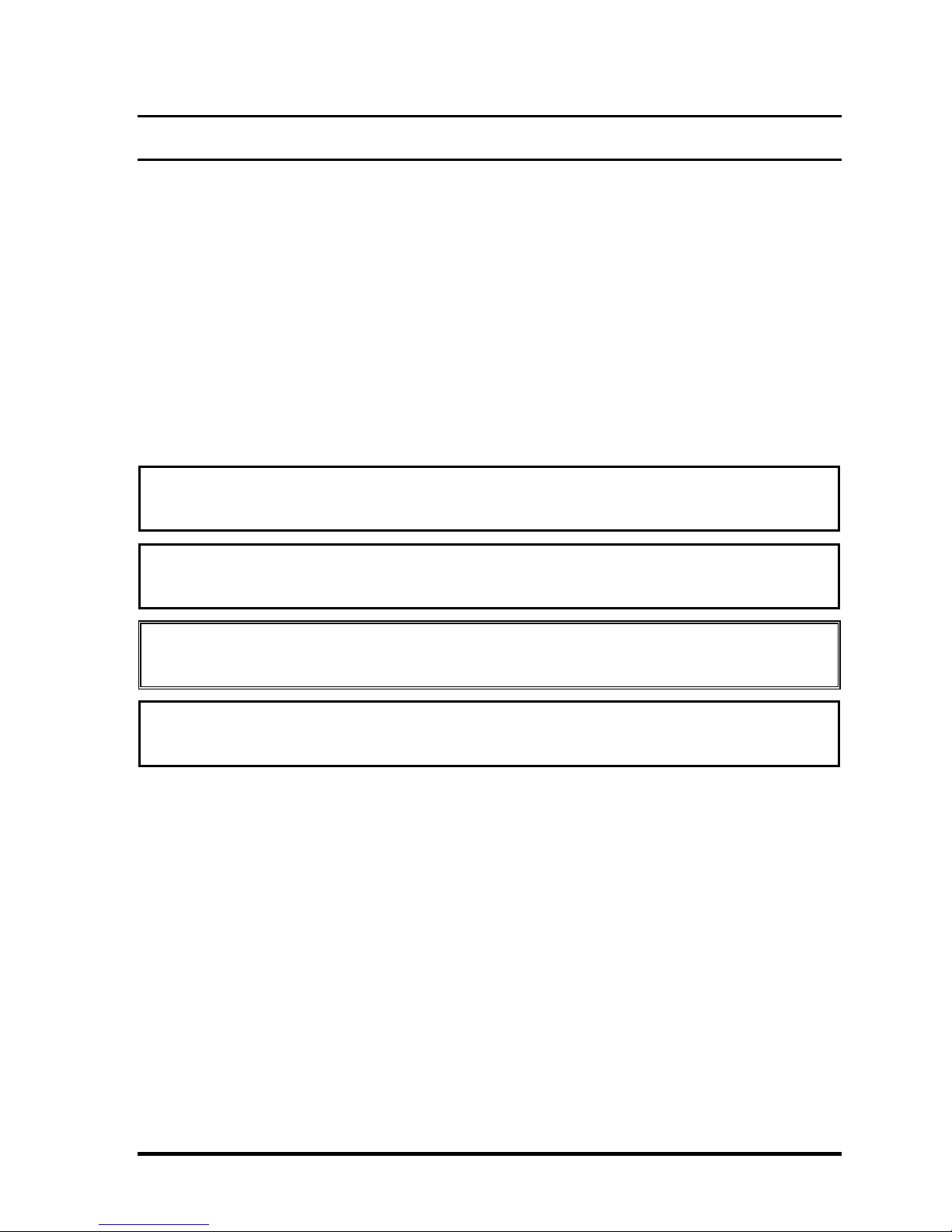
1.4.1 3.5-inch Floppy Disk Drive
The 3.5-inch FDD is a thin, high-performance reliable drive that supports 720KB (formatted)
2DD and 1.44MB (formatted) 2HD disks. The specifications for the FDD are listed in the
table below.
Item 2MB mode 1MB mode
Storage capacity (KB)
Unformatted
Formatted
Number of heads 2 2
Number of cylinders 80 80
Recording method Modified Frequency Modulation (MFM)
2,000
1,440
1,000
720
Satellite P20-25 Series Maintenance Manual 1-9

1 Hardware Overview 1.4 Removable Drives
1.4.2 DVD-R/-RW Drive
The DVD-R/-RW drive (Toshiba SD-R6112) accommodates either 12cm (4.72-inch) or 8cm
(3.15-inch) CDs or DVDs.
Read speeds
DVD-ROM Maximum 8 times faster rotational speed
DVD-RAM Standard rotational speed
CD-ROM Maximum 24 times faster rotational speed
Write speeds
CD-R 4,16 times faster rotational speed
CD-RW 4 times faster rotational speed
High-Speed CD-RW 4,10 times faster rotational speed
DVD-R 1, 2 times rotational speed
DVD-RW disc 1 times rotational speed
Access Speed
Average Random Access Time DVD-ROM: 115 ms (3.3-8X)
CD-ROM: 105 ms (10.3-24X)
DVD-RAM: 170 ms (4.7GB 1X)
Average Random Seek Time DVD-ROM: 105 ms (3.3-8X)
CD-ROM: 100 ms (10.3-24X)
DVD-RAM: 120 ms (4.7GB 1X)
Average Full Stroke Access Time DVD-ROM: 195 ms (3.3-8X)
CD-ROM: 180 ms (10.3-24X)
DVD-RAM: 350 ms (4.7GB 1X)
Buffer capacity 2 Mbytes (Max)
Supported formats
Applicable
Write Formats:
Applicable
CD
DVD
CD
Write Disc:
DVD
Applicable
CD
Read Disc:
DVD
CD-R/RW
DVD-R
DVD-RW
CD-R/RW [CD-DA, CD+(E)G, CD-MIDI, CD-ROM, CD-ROM XA,
MIXED MODE CD, CD-I, CD-I Bridge (Photo-CD, Video-CD),
Multisession CD (Photo-CD, CD-EXTRA, Portfolio)]
DVD-RW
DVD-R
CD-DA, CD+(E)G, CD-MIDI, CD-TEXT, CD-ROM, CD-ROM XA, CD-I, CD-I
Bridge (Photo-CD, Video-CD) Multisession CD (Phto-CD, CD-EXTRA, CD-R,
CD-RW, Portfolio), CD-R, CD-RW
DVD-ROM [DVD-5, DVD-9, DVD-10, DVD-18]
DVD-R
DVD-RW
DVD-RAM
1-10 Satellite P20-25 Series Maintenance Manual

1.4 Removable Drives 1 Hardware Overview
1.4.3 DVD-ROM Drive
The DVD-ROM drive (Toshiba SD-C2612 or Matsushita SR-8177) accommodates either
12cm (4.72-inch) or 8cm (3.15-inch) CDs or DVDs.
Transfer rates
Matsushita SR-8177: The DVD-ROM drive is able to read CD-ROM, CD-R data at 10.3X to
24X CAV mode speed and CD-RW data at 5.1X to 12X CAV mode
speed. The drive has a transfer rate of max. 3 600 kbyte/s for CDROM data, CD-R and max. 1 800 kbyte/s for CD-RW data. The drive
is able to read DVD disc at CAV mode speed. The drive has a transfer
rate of max. 11.08 Mbyte/s for DVD data.
Toshiba SD-C2612: Max.8X (DVD-ROM) / Max. 24X (CD-ROM)/2X (DVD-RAM
Ver.1.0)/1X (DVD-RAM Ver.2.1)
Max. 10,820 KByte/s (DVD-ROM)/Max. 3,600KByte/s (CD-ROM)
Sustained Transfer Rate
Buffer capacity
Matsushita SR-8177: 256 Kbytes (Max)
Toshiba SD-C2612 192 Kbytes (Max)
Supported formats
CD:
CD-Audio CD-ROM (mode 1 and mode 2) CD-ROM XA (mode 2, form 1 and form 2)
DVD:
CD-I Bridge CD-I (mode 2, form 1 and form 2) CD-TEXT
Video CD CD-RW Photo CD
CD-WO** Enhanced Music CD (CD Plus)** CD-I Ready**
CD+(E)G* CD-MIDI* CD-R*
DVD-5 DVD-9 DVD-10
DVD-18* DVD-RAM (2.6G/4.7G) DVD-R (3.95G/4.7G)
DVD-RW
* Toshiba SD-C2612 only
** Matsushita SR-8177only
Satellite P20-25 Series Maintenance Manual 1-11

1 Hardware Overview 1.4 Removable Drives
1.4.4 DVD Multi-Drive
The Matsushita UJ-811B DVD multi-drive is capable of driving either 12cm (4.72-inch) or
8cm (3.15-inch) DVDs and CDs without using an adaptor.
Read speed
DVD-ROM Max 8X CAV (MAX 10800 kB/s)
CD-ROM Max 24X CAV (MAX 3600 kB/s)
Write speed
CD-R : Max16X Zone CLV
CD-RW 4X CLV
High Speed CD-RW 8XCLV
DVD-R 2XCLV
DVD-RW 1X CLV
DVD-RAM 2X ZCLV ( 4.7GB)
Access Speed
DVD-ROM 180ms (Typ.) (Random)
CD-ROM 150ms(Typ.) (Random)
ATAPI Interface
PIO mode 16.6 MB/s :PIO mode4
DMA mode 16.6 MB/s :Multi word mode2
Ultra DMA mode 33.3 MB/s :Ultra DMA mode2
Buffer Memory 2MB
Supported formats
CD: CD-DA CD-ROM CD-R/W
CD-R CD-ROMXA CD-I Ready
Video CD PhotoCD(multi-session) Cd-Extra(CD+)
CD-TEXT
DVD: DVD-Video DVD-ROM DVD-R(3.9GB, 4.7GB)
DVD-RAM DVD-RW(Ver.1.1)
1-12 Satellite P20-25 Series Maintenance Manual

1.4 Removable Drives 1 Hardware Overview
1.4.5 Combo Drive
The CD-RW/DVD-ROM combo drive (Toshiba SD-R2412 or TEAC DW-224E-85) is
capable of driving either 12cm (4.72-inch) or 8cm (3.15-inch) DVDs and CDs without using
an adaptor.
Read speeds
DVD-ROM Maximum 8 times faster rotational speed
DVD-RAM Standard rotational speed
CD-ROM Maximum 24 times faster rotational speed
Write speeds
CD-R 4,8,16,24 times faster rotational speed
CD-RW 4 times faster rotational speed
High-Speed CD-RW 4,10 times faster rotational speed
Access Speed
Average Random Access Time DVD: 100 ms typ (Toshiba SD-R2412)
110 ms typ (TEAC DW-224E-85)
CD: 90 ms typ (10.3-24X)
DVD-RAM: 170 ms*
Average Random Seek Time DVD: 85 ms typ*
CD: 80 ms typ (10.3-24X)*
DVD-RAM: 130 ms typ*
Average Full Stroke Access Time DVD: 170 ms typ*
CD: 160 ms typ (10.3-24X)*
DVD-RAM: 300 ms*
* Toshiba SD-R2412
Buffer capacity 2 Mbytes (Max)
Supported formats
Applicable
CD
Write Formats:
Applicable
CD
Write Disc:
Applicable
CD
Read Disc:
DVD
CD-R
CD-RW
CD-R
CD-RW [CD-DA, CD+(E)G, CD-MIDI, CD-TEXT, CD-ROM, CD-ROM XA,
MIXED MODE CD, CD-I, CD-I Bridge (Photo-CD, Video-CD),
Multisession CD (Photo-CD, CD-EXTRA, Portfolio)]
CD-DA, CD+(E)G, CD-MIDI, CD-TEXT, CD-ROM, CD-ROM XA, MIXED
MODE CD, CD-I, CD-I Bridge (Photo-CD, Video-CD), Multisession CD (PhotoCD, CD-EXTRA, Portfolio, CD-R, CD-RW), CD-R, CD-RW
DVD-ROM [DVD-5, DVD-9, DVD-10, DVD-18]
DVD-R
DVD-RW
DVD-RAM
Satellite P20-25 Series Maintenance Manual 1-13

1 Hardware Overview 1.5 Power Supply
1.5 Power Supply
The power supply supplies seven different voltages to the system board and performs the
following functions:
1. A/D conversion
The EC uses 10-bit sampling for A/D conversion to determine the following values:
• AC adaptor current
• Battery and temperature
2. AC adaptor and battery check
The EC checks the following by A/D converted values:
• Battery installed
The EC checks the following by GPIO values:
• AC adaptor connected
3. Abnormal check
The EC determines whether the condition is abnormal, and if so, stores an error code
into the error register.
4. Input port management
The EC monitors the following input signal status:
• System power ON/OFF status
• Direct CD power ON/OFF status
5. Beep and LED control
Beep is caused by the low battery status.
The EC controls the following two kinds of LED
DC IN LED (one color: green)
• Green = indicates AC adaptor is connected
Battery LED (two colors: orange and green)
• Green solid = The battery is fully charged.
1-14 Satellite P20-25 Series Maintenance Manual

1.5 Power Supply 1 Hardware Overview
• Orange = The computer is quick-charging the battery / The battery is low.
6. Power ON/OFF sequence
When power is turned on or off, the EC starts the power on or off sequence.
• SQ0-4 = power ON sequence
• SQ5-B = power OFF sequence
7. Battery charging control
The EC controls the following.
• The quick charging ON/OFF
• The detection of full charge
8. Detection of the low battery
The EC detects the low battery point by the gas gauge.
• LB10M = The system will be driven by the battery for 12 more minutes.
• LB0 = The battery won't be able to drive the system after 3 minutes.
• LB1 = The battery can drive the system only during the suspend process.
• LB2 = The battery cannot drive the system.
9. New battery installation
When a new battery is installed, the EC communicates with the E
battery to read information of the newly installed battery.
10. Battery capacity calculation
The EC reads battery remaining and percentage capacity from the battery through
SMBus.
2
PROM in the
Satellite P20-25 Series Maintenance Manual 1-15
1 Hardware Overview 1.6 Batteries
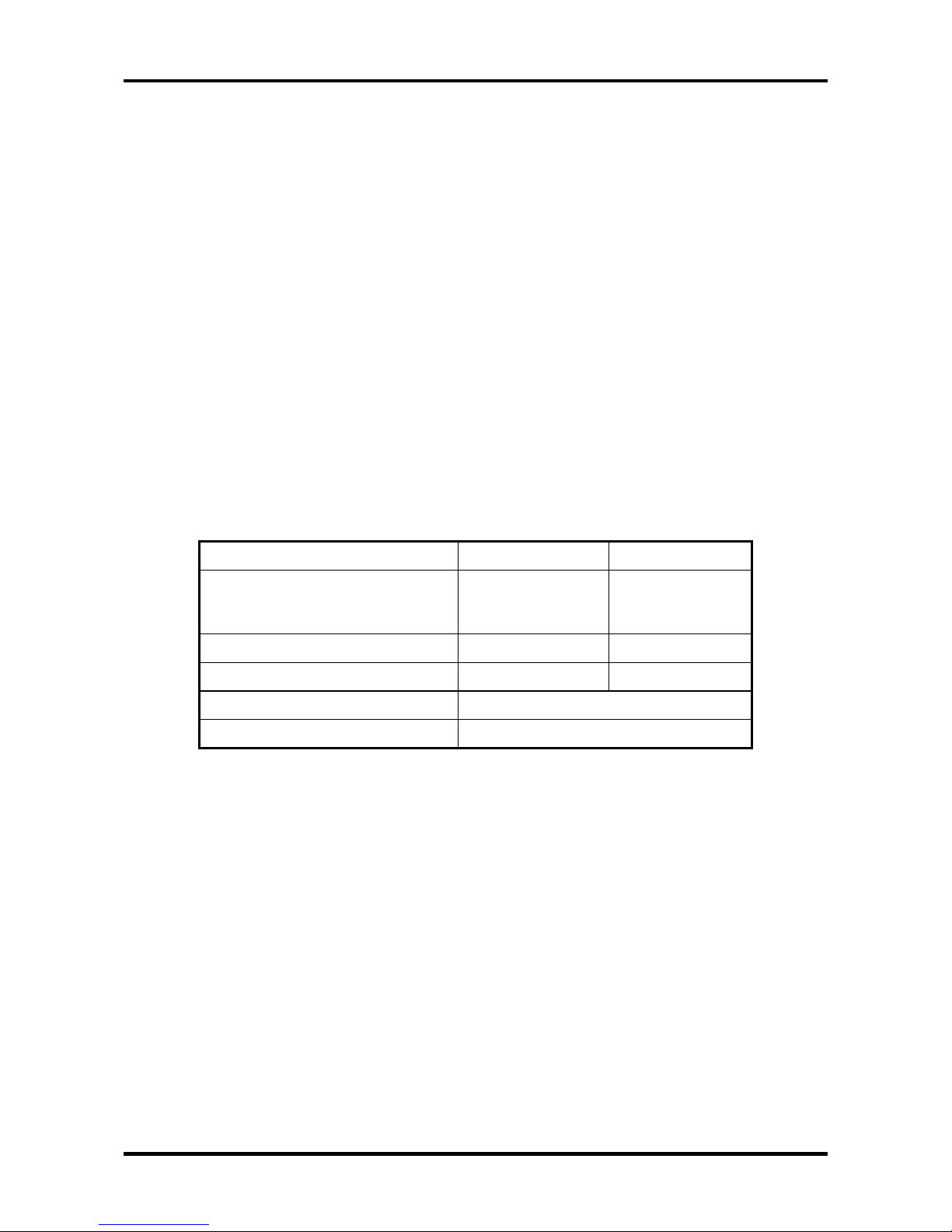
1.6 Batteries
The computer has two types of battery:
Main battery pack (18650 size)
RTC battery
The removable main battery pack is the computer’s main power source when the AC adaptor
is not attached.
The battery specifications are listed in the table below.
Battery name Material Output voltage Capacity
Main battery Lithium-Ion 14.8 V 6450mAH
RTC battery Lithium 3.3 V 15 mAh
1.6.1 Main Battery
Battery charging is controlled by a power supply microprocessor that is mounted on the
system board. The power supply microprocessor controls whether the charge is on or off and
detects a full charge when the AC adaptor and battery are attached to the computer. The
system charges the battery using quick charge or trickle charge.
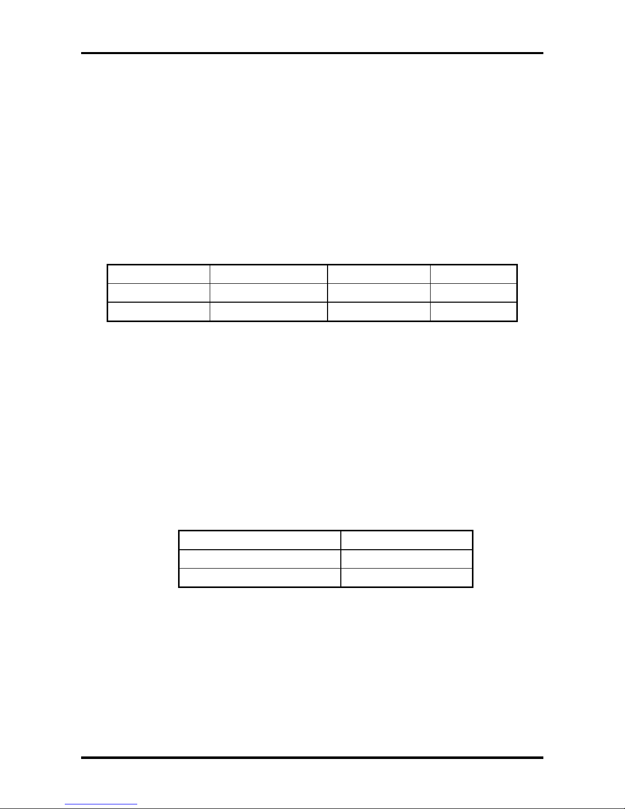
Quick Battery Charge
When the AC adaptor is attached, there are two types of quick charge: quick charge
when the system is powered off and normal charge when the system is powered on.
The times required for charges are listed in the table below.
Status Charging time
Normal charge (power on) 12 hours or longer
Quick charge (power off) About 4 hours
1-16 Satellite P20-25 Series Maintenance Manual
 Loading...