

Toshiba Satellite M640 Maintenance Manual

Toshiba Personal Computer
Satellite
Maintenance Manual
TOSHIBA CORPORATION

Copyright
© 2010 by Toshiba Corporation. All rights reserved. Under the copyright laws, this manual
cannot be reproduced in any form without the prior written permission of Toshiba. No
patent liability is assumed with respect to the use of the information contained herein.
Toshiba Personal Computer Satellite Maintenance Manual
First edition April.2010
Disclaimer
The information presented in this manual has been reviewed and validated for accuracy.
The included set of instructions and descriptions are accurate for the Satellite Series at the
time of this manual's production. However, succeeding computers and manuals are subject
to change without notice. Therefore, Toshiba assumes no liability for damages incurred
directly or indirectly from errors, omissions, or discrepancies between any succeeding
product and this manual.
Trademarks
IBM is a registered trademark, and OS/2 and PS/2 are trademarks of IBM Corporation.
Microsoft, MS-DOS, Windows, DirectSound and DirectMusic are registered trademarks of
Microsoft Corporation.
Intel and Pentium are registered trademarks, and SpeedStep is a trademark of Intel
Corporation.
Sound Blaster is a registered trademark of Creative Technology Ltd.
Centronics is a registered trademark of Centronics Data Computer Corporation.
Photo CD is a trademark of Eastman Kodak.
All other properties are trademarks or registered trademarks of their respective holders.
Satellite M640/ProM640 Series Maintenance Manual ii
Preface
This maintenance manual describes how to perform hardware service maintenance for the
Toshiba Personal Computer Satellite, referred to as the Satellite Series in this manual.
The procedures described in this manual are intended to help service technicians isolate
faulty Field Replaceable Units (FRUs) and replace them in the field.
SAFETY PRECAUTIONS
Four types of messages are used in this manual to bring important information to your
attention. Each of these messages will be italicized and identified as shown below.
DANGER: “Danger” indicates the existence of a hazard that could result in death or
serious bodily injury if the safety instruction is not observed.
WARNING: “Warning” indicates the existence of a hazard that could result in bodily
injury if the safety instruction is not observed.
CAUTION: “Caution” indicates the existence of a hazard that could result in property
damage if the safety instruction is not observed.
NOTE: “Note” contains general information that relates to your safe maintenance
service.
Improper repair of the computer may result in safety hazards. Toshiba requires service
technicians and authorized dealers or service providers to ensure the following safety
precautions are adhered to strictly.
Be sure to fasten screws securely with the right screwdriver. If a screw is not fully
fastened, it could come loose, creating a danger of a short circuit, which could cause
overheating, smoke or fire.
If you replace the battery pack or RTC battery, be sure to use only the same model
battery or an equivalent battery recommended by Toshiba. Installation of the wrong
battery can cause the battery to explode.
Satellite M640/ProM640 Series Maintenance Manual iii

The manual is divided into the following parts:
Chapter 1 Hardware Overview describes the Satellite Series system unit and
each FRU.
Chapter 2 Troubleshooting Procedures explains how to diagnose and resolve
FRU problems.
Chapter 3 Test and Diagnostics describes how to perform test and diagnostic
operations for maintenance service.
Chapter 4 Replacement Procedures describes the removal and replacement of
the FRUs.
Appendices The appendices describe the following:
Handling the LCD module
Board layout
Pin assignments
Keyboard scan/character codes
Key layout
Screw torque list
Reliability
Conventions
This manual uses the following formats to describe, identify, and highlight terms and
operating procedures.
Acronyms
On the first appearance and whenever necessary for clarification, acronyms are enclosed in
parentheses following their definition. For example:
Read Only Memory (ROM)
Keys
Keys are used in the text to describe many operations. The key top symbol as it appears on
the keyboard is printed in boldface type.
Key operation
Satellite M640/ProM640 Series Maintenance Manual iv

Some operations require you to simultaneously use two or more keys. We identify such
operations by the key top symbols separated by a plus (+) sign. For example, Ctrl + Pause
(Break) means you must hold down Ctrl and at the same time press Pause (Break). If
three keys are used, hold down the first two and at the same time press the third.
User input
Text that you are instructed to type in is shown in the boldface type below:
DISKCOPY A: B:
The display
Text generated by the computer that appears on its display is presented in the typeface
below:
Format complete
System transferred
Satellite M640/ProM640 Series Maintenance Manual v

Table of Contents
Chapter 1 Hardware Overview
1.1 Features .................................................................................................................. 1-1
1.2 2.5-inch HDD....................................................................................................... 1-11
1.3 DVD Super Multi (+-R Double Layer) ................................................................ 1-12
1.4 BD-RE and BD-Combo drives............................................................................. 1-13
1.5 Power Supply ....................................................................................................... 1-15
1.6 Batteries................................................................................................................ 1-17
1.6.1 Main Battery ......................................................................................... 1-17
1.6.2 Battery Charging Control ..................................................................... 1-17
1.6.3 RTC Battery.......................................................................................... 1-18
Chapter 2 Troubleshooting Procedures
2.1 Troubleshooting Introduction .............................................................................................. 3
2.2 Troubleshooting Flowchart ................................................................................................. 4
2.3 Power Supply Troubleshooting ........................................................................................... 9
2.4 Display Troubleshooting ................................................................................................... 14
2.5 Keyboard Troubleshooting ................................................................................................ 17
2.6 External USB Devices Troubleshooting ........................................................................... 19
2.7 Touch Pad Troubleshooting .............................................................................................. 21
2.8 Speaker Troubleshooting ................................................................................................... 23
2.9 Optical Drive Troubleshooting .......................................................................................... 25
2.10 Modem Troubleshooting ................................................................................................... 28
2.11 Express card Troubleshooting ........................................................................................... 30
2.12 Wireless LAN Troubleshooting ........................................................................................ 32
2.13 Camera Troubleshooting ................................................................................................... 34
2.14 Bluetooth Troubleshooting ................................................................................................ 36
2.15 Bridge Media Slot Troubleshooting .................................................................................. 38
Satellite M640/ProM640 Series Maintenance Manual vi

2.16 HDD/SSD Troubleshooting ..................................................................................................... 40
2.17 CRT Troubleshooting .............................................................................................................. 42
2.18 HDMI Troubleshooting ........................................................................................................... 44
2.19 MIC Troubleshooting ............................................................................................................... 46
2.20 Finger printer troubleshooting ................................................................................................. 48
2.21 E-SATA Troubleshooting ........................................................................................................ 50
2.22 3D Sensor Troubleshooting ..................................................................................................... 52
2.23 Sleep & Charge Troubleshooting ............................................................................................. 54
2.24 Sleep & Play music Troubleshooting ...................................................................................... 56
2.25 3G Troubleshooting ................................................................................................................. 58
2.26 LAN Troubleshooting .............................................................................................................. 61
2.27 Ambient Light Sensor Troubleshooting ................................................................................... 63
2.28 Wimax Troubleshooting .......................................................................................................... 65
Chapter 3 Tests and Diagnostics
3.1 The Diagnostic Test ............................................................................................................................ 3
3.2 Executing the Diagnostic Test ............................................................................................................ 4
3.3 Display Configuration ......................................................................................................................... 7
3.4 Audio sound test ................................................................................................................................. 8
3.5 Fan ON/OFF/Speed Test ................................................................................................................... 11
3.6 Main Battery Charge Test ................................................................................................................. 13
3.7 FDD Test ........................................................................................................................................... 15
3.8 Memory check .................................................................................................................................. 16
3.9 Keyboard Test ................................................................................................................................... 19
3.10 Mouse (Pad) Test ............................................................................................................................ 21
3.11 LCD Pixels Mode Test .................................................................................................................... 22
3.12 Magnetic Switch Test ..................................................................................................................... 23
3.13 LAN Test ........................................................................................................................................ 25
3.14 RTC Test ......................................................................................................................................... 27
3.15 BUTTON TEST .............................................................................................................................. 28
3.16 1st HDD Test .................................................................................................................................. 30
Satellite M640/ProM640 Series Maintenance Manual vii

3.17 Read DMI ................................................................................................................................... 32
3.18 Write DMI .................................................................................................................................. 33
3.19 3D Sensor Test ........................................................................................................................... 35
3.20 TP TYPE R/W TEST ................................................................................................................. 39
3.21 EE--PROM Setting ..................................................................................................................... 42
3.22 Toshiba Logo set ........................................................................................................................ 46
3.23 Dynabook Logo set .................................................................................................................... 48
Chapter 4 Replacement Procedures
Figure 4.1 Removing the battery pack................................................................................. 4-8
Figure 4.3 Removing the memory from the laptop..................................................... 4-11
Figure 4.4 Removing the HDD door.................................................................................. 4-13
Figure 4.5 Removing the HDD pack from the HDD bay .................................................. 4-14
Figure 4.6 Removing the HDD aluminum foil ................................................................. 4-15
Figure 4.7 Removing the WLAN card............................................................................... 4-17
Figure 4.8 Removing the WWAN card ............................................................................... 4-19
Figure 4.9 Removing the Tray-load ODD........................................................................... 4-21
Figure 4.10 Removing the ODD bracket from the Tray-load ODD.................................... 4-22
Figure 4.11 Hooks on the inside of the Tray-load ODD bezel ............................................ 4-23
Figure 4.12 Removing the keyboard screws and pushing the keyboard free ...................... 4-24
Figure 4.13 Lifting the keyboard ......................................................................................... 4-25
Figure 4.14 Disconnecting the keyboard FPC..................................................................... 4-26
Figure 4.15 Disconnecting the keyboard backlight FFC..................................................... 4-27
Figure 4.16 Removing logic upper asembly screws from the bottom of the laptop............ 4-28
Figure 4.17 Removing four logic upper assembly screws and disconnecting four cables .. 4-29
Figure 4.18 Removing the logic upper assembly from the laptop....................................... 4-30
Figure 4.19 Removing the speakers..................................................................................... 4-32
Figure 4.20 Removing the logo board ................................................................................. 4-33
Figure 4.21 Removing the touch pad light bar .................................................................... 4-35
Figure 4.22 Disconnecting the touch pad switch board FFC and finger print board FFC... 4-36
Figure 4.23 Removing the Bluetooth module...................................................................... 4-37
Satellite M640/ProM640 Series Maintenance Manual viii

Figure 4.24 Disconnecting the Bluetooth cable................................................................... 4-38
Figure 4.25 Disconnecting the power membrane FFC........................................................ 4-39
Figure 4.26 Removing the motherboard from the logic lower assembly ............................ 4-40
Figure 4.27 Removing the thermal fan screw...................................................................... 4-41
Figure 4.28 Removing the Thermal Module spring screws................................................. 4-42
Figure 4.29 Removing the Thermal Module spring screws................................................. 4-43
Figure 4.30 Removing the CPU........................................................................................... 4-44
Figure 4.31 Reapplying the Shinetsu 7762 grease on the thermal module and removing any
release papers .................................................................................................................... 4-46
Figure 4.32 Removing the Slot-load ODD........................................................................ 4-47
Figure 4.33 Disassembling the Slot-load ODD.................................................................. 4-48
Figure 4.34 Removing the membrane power board........................................................... 4-50
Figure 4.35 Removing the display assembly ..................................................................... 4-51
Figure 4.36 Removing the LCD bezel screws ................................................................... 4-53
Figure 4.37 Prying up the LCD bezel ................................................................................ 4-54
Figure 4.38 Unhooking the hinge caps from the LCD hinges ........................................... 4-55
Figure 4.39 Removing the LCD module from the LCD cover assembly .......................... 4-56
Figure 4.40 Disconnecting the camera cable from the camera.......................................... 4-57
Figure 4.41 Removing the LCD hinges from the LCD panel............................................ 4-58
Figure 4.42 Removing the LVDS cable from the LCD panel ........................................... 4-59
Figure 4.43 Installing the LCD hinges............................................................................... 4-60
Figure 4.44 Removing the camera module ....................................................................... 4-61
Figure 4.45 Removing the antennas from the LCD cover assembly ................................. 4-62
Appendices
Appendix A Handling the LCD Module .......................................................................................... A-1
Appendix B Board Layout ............................................................................................................... B-1
Appendix C Pin Assignments ........................................................................................................... C-1
Appendix D Keyboard Scan/Character Codes ................................................................................. D-1
Appendix E Key Layout ................................................................................................................... E-1
Appendix F Series Screw Torque List .............................................................................................. F-1
Appendix G Reliability ..................................................................................................................... G-1
Satellite M640/ProM640 Series Maintenance Manual ix

Chapter 1
Hardware Overview

1 Hardware Overview
Satellite M640/Pro M640 Maintenance Manual 1-ii
Chapter 1 Contents
1.1 Features .................................................................................................................. 1-1
1.2 2.5-inch HDD.......................................................................................................1-11
1.3 DVD Super Multi (+-R Double Layer)................................................................1-12
1.4 BD-RE and BD-Combo drives.............................................. ... ............................1-13
1.5 Power Supply ........................................................ ...............................................1-15
1.6 Batteries................................................................................................................ 1-17
1.6.1 Main Battery........................ .. ........................................................... ... .1-17
1.6.2 Battery Charging Control ..................................................................... 1-17
1.6.3 RTC Battery..........................................................................................1-18

1 Hardware Overview
Satellite M640/Pro M640 Maintenance Manual 1-iii
Figures
Figure 1-1A
ID Parts Description Placement Part A.......................................................... 1-6
Figure 1-2 SATA HDD .................................. .............................................................. .1-11
Figure 1-3 DVD Super Multi Drive ..............................................................................1-12
Figure 1-4 BD-RE or BD-Combo drive (depending on the model)..............................1-13
Tables
Table 1-1
HDD Specifications .....................................................................................1-11
Table 1-2 DVD Super Multi Drive Specifications.......................................................1-12
Table 1-3 Blu-ray Disc Drive specifications................................................................1-14
Table 1-4 Quick/Normal Charging Time.....................................................................1-17

1.1 Features 1 Hardware Overview
Satellite M600/M640/M645/M647 Maintenance Manual 1-1
1.1 Features
The Toshiba Satellite M600/M640/M645/M647 Series computer is a full-size PC notebook
based on a Dual Core Processor, providing high-speed processing capabilities and advanced
features. The computer employs a lithium ion battery that allows it to operate without a DC-in
connection for extended periods of time. The display uses a 14 inch TFT LCD panel. The PGA
socket supports BTO for the CPU so that the system can be designed to suit the cust omer’s needs.
The computer has the following features:
Processor (BTO)
The computer is equipped with the following Intel
®
processor:
Intel
®
Arrandale Processor
Memory (BTO)
The computer has two SODIMM slots that come standard with 1GB, 2GB or 4GB BTO to
meet various memory requirements. It can incorporate up to 8 GB of m ain memory. It
supports DDR3 at 800MHz/1066MHz, depending on the CPU.
Battery Pack
The computer is powered by one rechargeable and removable lithium ion battery pack. The
capacity is either 6-cell or 12-cell, depending on the model of the computer. The computer
also offers a high capacity 6-cell battery (BTO).
Hard Disk Drive (HDD) (BTO)
The computer accommodates one 9.5 mm HDD with the following storage options:
y 250/320/500/640GB SATA (5,400rpm)
y 320/500GB SATA (7,200rpm)
y 64GB/128/256/512GB TOSHIBA solid-state drive (SSD) in the future
ODD (BTO)
y 12.7mm height DVD Super Multi drive (supporting DVD-R / -RW / +R / +RW / -RAM
/ -RDL / +RDL / CD-R / CD-RW) Double Layer with Labelflash
y 12.7mm height BD-Combo drive (supporting BD/DVD/CD/ DVD-R / -RW / +R / +RW
/ -RAM / -RDL / +RDL / CD-R / CD-RW)

1 Hardware Overview 1.1 Features
Satellite M600/M640/M645/M647 Maintenance Manual 1-2
y 12.7mm height BD-RE drive (supporting BD/DVD/CD/BD-R/BD-RE/ DVD-R / -RW /
+R / +RW / -RAM / -RDL / +RDL / CD-R / CD-RW)
Display (BTO)
The computer display features the following LCD panel:
y 14"W 1366 x 768: color TFT/HD
Graphics (BTO)
Intel
®
5 Series Chipset model integrated graphics display
Nvidia N11P-LP1, N11M-OP1, N11P-LP2, N11M-GE2 for external graphics support
( DDR3, 512MB/1GB/2GB)
Keyboard (BTO)
The computer is equipped with an illuminated Toshiba 2010 A4 keyboard with 86/87 keys,
including keyboard overlays to provide all the features of the 104-key enhanced keyboard.
It is a Windows 7 compliant keyboard featuring a Windows key and application keys.
Pointing Device
The integrated Wide Touch Pad and two control buttons in the palm rest allow for control
of the on-screen pointer and supports functions such as multi-touch touchpad gestures and
window scrolling. The device also features a touchpad on/off button and an LED light bar.
External Monitor Port
Dual external monitor functionality is supported by the VGA port and HDMI port.

1.1 Features 1 Hardware Overview
Satellite M600/M640/M645/M647 Maintenance Manual 1-3
Universal Serial Bus (USB) Ports
The computer has three USB 2.0 ports. It is supported to daisy-chain a maximum of 127
USB devices. The serial data transfer rate is 480 Mbps or 12 Mbps and 1.5 Mbps. These
ports support PnP installation and hot plugging.
eSATA/USB Combo Port
The external eSATA/USB combo port executes high-speed data transfer s to external
devices and now supports shielded cable lengths of up to 2 meters outside the computer.
The port also complies with the USB 2.0 standard and supports Sleep and Charge
functionality.
Express Card Slot
The internal Express Card slot is a universal slot. This slot supports ExpressCard34 and the
slot is covered with a dummy card. It also supports USB/PCI Express signals.
Bridge Media Slot
This slot allows you to insert SD, MiniSD/ MicroSD (through adapter), Memory
Stick/Memory Stick Duo (through adaptor), Memory Stick Pro/Memory Stick Pro Duo
(through adaptor), xD and MMC memory cards. It supports High-speed SD, SDHC and
SDXC. An I/O port heel cover is needed. This model does not support CF or Smart Media
cards.
Sound system
The integrated sound system provides support for the computer’s internal speakers and
microphone, also allowing an external microphone and headphones to be connected via the
appropriate jacks. It is composed of two Harman/Kardon OdysseyII 8cc internal speakers,
an internal microphone (equipped with echo cancellation) as well as standard MIC-IN.
Internal Camera (BTO)
The internal camera supports 1.3M pixels without Auto Macro and comes with a blue LED
indicator. (The internal camera is BTO with the internal microphone). The camera is not a
rotation type.
HDMI Out Port (BTO)
The HDMI out port complies with the HDMI 1.3 specification and the HDMI-CEC
standard. The port can connect with a Type C connector HDMI cable. The port can also
connect a Type A connector HDMI cable by using a Type A-to-Type C cable. The port

1 Hardware Overview 1.1 Features
Satellite M600/M640/M645/M647 Maintenance Manual 1-4
supports sending and receiving of SD and HD video/audio and control signals.
Headphones/Line out Jack
This jack connects digital speakers or stereo headphones (16 ohm minimum). When
connected to digital speakers or headphones, the internal speaker is automatically disabled.
Microphone/ Line-in Jack
A 3.5mm mini microphone jack enables connection of a three-conductor microphone for
monaural input and also enables the connection of a stereo device for audio input. The
Sleep and Music function enables audio playback from a connected audio device even when
the computer is in Sleep or Hibernation mode.
LAN (BTO)
The computer has built-in support for 10M/100M Ethernet LAN (10/100 megabits per
second, 10/100BASE-T) or Gigabit Ethernet LAN (1000 megabits per second, 1000BASET). It employs RTL8105E for 10M/100Mbit LAN or RTL8111E for Gigabit LAN. It is preinstalled as a standard device in some markets.
Wireless LAN (BTO)
Some computers in this series are equipped with a Wireless LAN card. This WLAN module
may come in with the following types (depending on the model):
Realtek 802.11 b/g/n 8188CE (1x1)
Realtek 802.11 b/g 8191SE (1x2)
Atheros 802.11 b/g/n HB95 (1x1)
Intel 802.1 1 a/b/g, a/b/n PumaPeak (2x2)
Broadcom 802.11 b/g/n, b/g 4313 (WLAN/BT) w/Bluetooth V3.0+HS
Internal Modem (BTO)
Some models are equipped with an integrated modem. The integrated modem provides
capability for data and fax communications that support the V.90 (V.92) standards and
includes a modem jack for connection to the telephone line. Please note that both the V.90
and V.92 standards are only supported in the USA, Canada, United Kingdom, France,
Germany and Australia - only the V.90 standard is supported in other regions. You should
also be aware that the speed of data and fax transfer will depend on the analog telephone
line conditions. The integrated model is only installed as a standard device in some mark ets.
This internal modem comes with MDC 1.5 solution (Azalia interface).

1.1 Features 1 Hardware Overview
Satellite M600/M640/M645/M647 Maintenance Manual 1-5
Bluetooth (BTO)
Some computers in this series offer Bluetooth wireless communication functionality, which
eliminates the need for cables between electronic devices such as computers and printers.
When implemented, Bluetooth provides a fast, reliable and secure means to achieve
wireless communication in a small space. This module is Version 2.1 + EDR (Antenna on
Module type).
Fingerprint Sensor (BTO)
The computer has a fingerprint utility installed for the purpose of enrolling and recognizing
fingerprints. By enrolling the ID and password to the fingerprint authentication device, it is
no longer necessary to input the password from the keyboard . The Fingerprint sensor is
located at the center of the Touch Pad panel and is an Authentec AES1660.
1 Hardware Overview 1.1 Features
Satellite M600/M640/M645/M647 Maintenance Manual 1-6
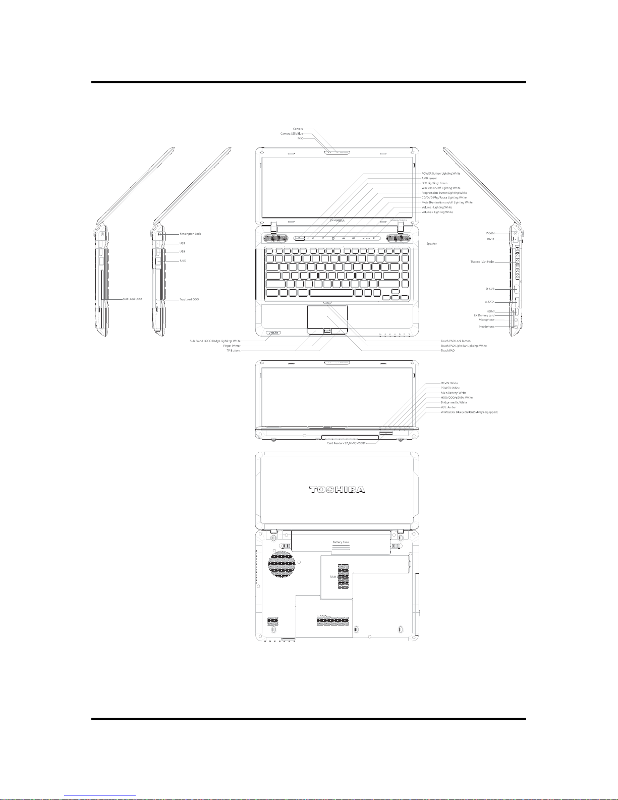
Figure 1-1A shows the computer and its system unit configuration.
Figure 1-1A ID Parts Description Placement Part A

1.1 Features 1 Hardware Overview
Satellite M600/M640/M645/M647 Maintenance Manual 1-7

1 Hardware Overview 1.1 Features
Satellite M600/M640/M645/M647 Maintenance Manual 1-8

1.1 Features 1 Hardware Overview
Satellite M600/M640/M645/M647 Maintenance Manual 1-9
The system unit of the computer consists of the following components:
Processor (BTO)
The computer is equipped with the following Intel
®
processor:
Intel
®
Arrandale Processor
Memory (BTO)
The computer has two SODIMM slots that come standard with 1GB, 2GB or 4GB BTO to
meet various memory requirements. It can incorporate up to 8 GB of m ain memory. It
supports DDR3 at 800MHz/1066MHz, depending on the CPU.
BIOS ROM (EEPROM)
The system BIOS uses 4MB flash ROM and the Embedded Controller (EC) BIOS uses
256KB flash ROM, depending on the PCH type. The BIOS is ACPI-compliant. The fl ash
utility can be used to program both system and keyboard BIOS at the same time.
System Controllers
Advanced Power Management 1.2 support
Energy Star® Revision 5.0
ACPI2.0 b and PC2001 compliant
Support SMBus specification V2.0
Hot keys for system control
Audio volume output control
External LED control
Battery scope report and control
Sticky key support
Power switch control
Two host interface channels support
Supports three independent devices
Internal Keyboard count ry selection
Magnetic lid switch

1 Hardware Overview 1.1 Features
Satellite M600/M640/M645/M647 Maintenance Manual 1-10
Graphics Controller
Intel
®
5 Series Chipset as integrated graphics solution
Following External Graphic solution:
− NVIDIA
®
N11P-LP1/N11M-OP1/N11P-LP2/N11M-GE2
HDMI 1.3-CEC Support
DVI-D supported by conversion cable from HDMI
Express Card Controller
Support USB/PCI Express signals
One Express Card slot 34
Audio Controller
Realtek Azalia ALC269-VB5
One Audio-in port : Mic.-in/Line-in
One Audio-out port: Headphone-out / Line-out
Internal Microphone (wit h Internal Camera, MIC with echo cancellation)
Volume control: Digital control, feather touch button, no mute function
Microsoft inbox audio driver support
Software EQ support
Synchronize to change video and audio output to HDMI
Dolby Sound Room support (BTO by region)
MAXX audio support (BTO by region)
Sleep and Music support
Wireless LAN Controller
Realtek 802.11 b/g/n 8188CE (1x1)
Realtek 802.11 b/g 8191SE (1x2)
Atheros 802.11 b/g/n HB95 (1x1)
Intel 802.1 1 a/b/g, a/b/n PumaPeak (2x2)
Broadcom 802.11 b/g/n, b/g 4313 (WLAN/BT) w/Bluetooth V3.0+HS
1.2 2.5-inch HDD 1 Hardware Overview
Satellite M600/M640/M645/M647 Maintenance Manual 1-11
1.2 2.5-inch HDD
The computer contains an extremely low-profile , lightweight and high-performance HDD. The
HDD incorporates 9.5 mm height magnetic disk and mini-Winchest er type magnetic heads. The
HDD interface conforms to Serial ATA. Storage capacities supported are 250, 320, 500 and
640GB.
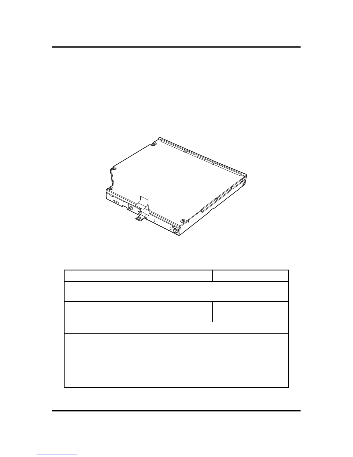
The HDD is shown in Figure 1-2 and some of its specifications are listed in Table 1- 1.
Figure 1-2 SATA HDD
Table 1-1 HDD Specifications
Item
Specifications
Capacity (GB)
250G 320 GB
Rotational Speed (RPM)
5,400 RPM 5,400 or 7,200 RPM
Height
9.5 mm 9.5 mm
User Data Sectors
488,397,168 625,142,448
Bytes / Sector 512 512
Item
Specifications
Capacity (GB)
500G 640 GB
Rotational Speed (RPM)
5,400 or 7,200 RPM 5,400 RPM
Height
9.5 mm 9.5 mm
User Data Sectors
976,773,168 1,250,263,728
Bytes / Sector 512 512
1 Hardware Overview 1.3 DVD Super Multi (+ -R Double Layer)
Satellite M600/M640/M645/M647 Maintenance Manual 1-12
1.3 DVD Super Multi (+-R Double Layer)
The DVD Super Multi drive accepts 12-cm (4.72-inch) and 8-cm (3.15-i nch) disc s. At maximum,
the drive can play back a DVD at 8x speed, read CD-ROM at 24x speed, and write CD-R at 24x
speed, CD-RW at 16x speed, DVD-R at 8x speed, DVD-RW at 6x speed, DVD+R at 8x speed,
DVD+R (DL) at 6x speed, DVD-R (DL) at 6x speed, DVD+RW at 8x speed and DVD-RAM at
5x speed.
The DVD Super Multi drive is shown in Figure 1-3 and its specifications are li sted in Table 1-2.
Figure 1-3 DVD Super Multi Drive
Table 1-2 DVD Super Multi Drive Specifications
Item DVD-ROM Mode CD-ROM Mode
33.3 (U-DMA transfer mode 2)
Data Transfer Rate (Mbytes/s)
16.6 (PIO mode 4, Multiword DMA mode 2)
Access Time (ms)
Average Random Access 130 130
Data Buffer Size (Mbytes) 2MB
DVD:
DVD-VIDEO, DVD-ROM, DVD-R, DVD-RW, DVD-RAM, DVD+R,
DVD+-R (Double Layer), DVD+RW.
CD:
Formats Supported
CD-DA, CD-ROM, CD-R, CD-RW, CD-ROMXA, Photo CD
(Multi-Session), Video CD, CD-Extra (CD+), CD-Text.

1.4 BD-RE and BD-Combo drives 1 Hardware Overview
Satellite M600/M640/M645/M647 Maintenance Manual 1-13
1.4 BD-RE and BD-Combo drives
The BD-RE and BD-Combo drives accept 12-cm (4.72-inch) and 8-cm (3.15-inch) discs and can
play BDs, DVDs and CDs. At maximum the drives can playback BD at 6x speed, DVD at 8x
speed, read CD-ROM at 24x speed.
The BD-RE and BD-Combo drives let you record data to writable CD/DVD discs. The drives
can write CD-R at 24x speed, CD-RW at 16x speed, DVD-R at 8x speed, DVD-RW at 6x speed,
DVD+R at 8x speed, DVD+R (DL) at 4x speed, DVD-R (DL) at 4x speed, DVD+RW at 4x
speed and DVD-RAM at 5x speed.
In addition to being able to write to recordable CD/DVD discs, th e BD-RE drive can write to
BD-R as 6x speed, BD-R (DL) at 4x speed, BD-RE at 2x speed and BD-RE (DL) at 2x speed.
Figure 1-4 BD-RE or BD-Combo drive (depending on the model)

1 Hardware Overview 1.4 BD-RE and BD-Combo drives
Satellite M600/M640/M645/M647 Maintenance Manual 1-14
Table 1-3 Blu-ray Disc Drive specifications
Item BD-ROM Mode DVD-ROM Mode CD-ROM Mode
33.3 (U-DMA transfer mode 2)
Data Transfer Rate (Mbytes/s)
16.6 (PIO mode 4, Multiword DMA mode 2)
Access Time (ms)
Average Random Access 130
Data Buffer Size (Mbytes) 2MB
BD-Combo: BD-RE:
BD-ROM BD-ROM, BD-R (DL), BD-RE (DL)
DVD:
DVD-VIDEO, DVD-ROM, DVD-R, DVD-RW, DVD-RAM, DVD+R,
DVD+-R (Double Layer), DVD+RW.
CD:
Formats Supported
CD-DA, CD-ROM, CD-R, CD-RW, CD-ROMXA, Photo CD
(Multi-Session), Video CD, CD-Extra (CD+), CD-Text.

1.5 Power Supply 1 Hardware Overview
Satellite M600/M640/M645/M647 Maintenance Manual 1-15
1.5 Power Supply
The power supply unit provides constant voltage (19V) for the system board and performs the
following functions:
1. Power input monitor
y Checks whether the AC adapter (DC power supply) is connected to the computer.
y Checks whether the battery pack is connected to the computer.
y Monitors the DC power supply input voltage (AC Adapter output voltage).
2. Power supply's internal control
y Turns on and off the battery pack charging power supply.
y Issues a charging curren t instruction to the PWM control IC of the battery pack charg ing
power supply.
y Controls the suppl y of DC power supply input (AC Adapter output) to the power supply
unit.
y Controls the supply of power to the system block (load/logic circuit side).
y Controls forced shutdown if the power supply malfunctions.
3. Logic circuit control
y Instructs the gate array to enable/disable tuning the power on.
y Controls power-on/off operation.
4. Status display
y Turns on the Power LED (White or Amber color).
y Battery indicator (White or Amber color).
y DC-IN indicator (White color).
5. External interface
y Performs communication through the I2C bus (via the internal EC/KBC).
y Transfers the power supply operation mode.

1 Hardware Overview 1.5 Power Supply
Satellite M600/M640/M645/M647 Maintenance Manual 1-16
6. Output monitor
y Monitors the voltage output to the system block (load/logic circuit side).
y Monitors the voltage, over-voltage, input/output current of the battery pack.
y Monitors the internal temperature of the battery pack.
y Monitors the supply voltage from the AC adapter.
1.6 Batteries 1 Hardware Overview
Satellite M600/M640/M645/M647 Maintenance Manual 1-17
1.6 Batteries
The computer has the following two types of batteries:
Main Battery Pack
Real Time Clock (RTC) Battery
1.6.1 Main Battery
The main battery pack serves as the computer's main power source when the AC adapter is not
attached. The main battery maintains the state of the computer when the AC adapter is detached.
1.6.2 Battery Charging Control
Battery charging is controlled by EC KB926. When the AC adapter and battery pack are attached
to the computer, the EC KB926 controls the charge on/off state and detects a full charge.
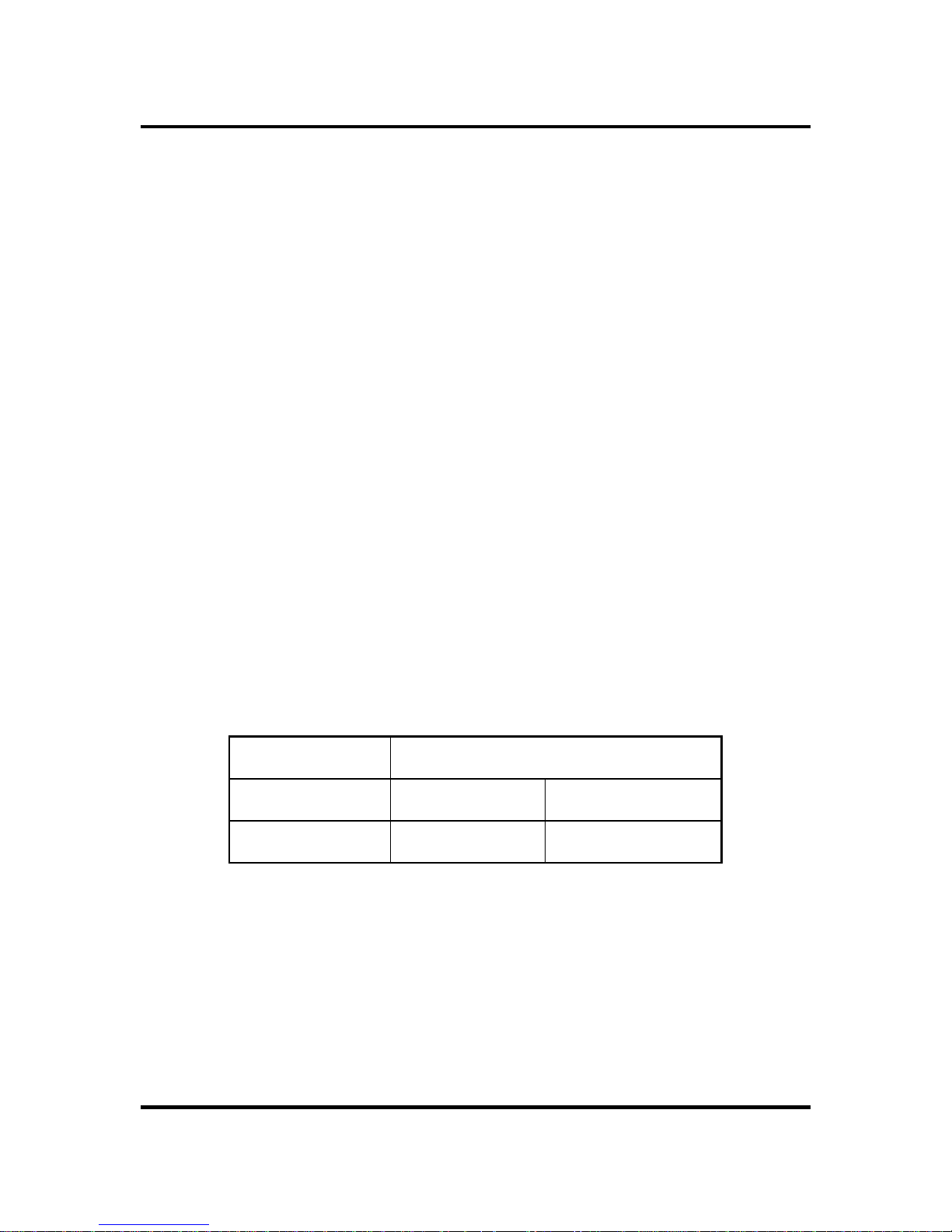
Battery Charge
When the AC adapter is attached, the battery is charged by off-state charge when the system
is powered off or by on-state charge when it is powered on.
Table 1-4 Quick/Normal Charging Time
State Charge Time
Off-State Charge 6/12 Cell About 4 hours
On-State Charge 6/12 Cell About 12 hours

1 Hardware Overview 1.6 Batteries
Satellite M600/M640/M645/M647 Maintenance Manual 1-18
NOTE: The time required for normal charge depends on the power consumption by the
system. Using a fluorescent lamp and frequently accessing the disk consumes more power
and lengthens the charge time.
Any of the following can stop battery charge:
1. The battery becomes fully charged.
2. The AC adapter or battery pack is removed.
3. The battery or AC adapter voltag e is abnormal.
Detection of full charge
A full charge is detected only when the battery is being charged by quick or normal charge.
A full charge is detected when either of the following conditions is met:
1. The current in the battery char ging circuit drops below the predetermined value.
2. The charging time exceeds the fix ed limit.
1.6.3 RTC Battery
The RTC battery provides power to maintain the current date, time and other system information
in memory while the computer is turned off.
 Loading...