

Page 1

Toshiba Personal Computer
Satellite M30-35 Series
Maintenance Manual
TOSHIBA CORPORATION
File Number 960-455
Page 2

Copyright
© 2003 by Toshiba Corporation. All rights reserved. Under the copyright laws, this manual
cannot be reproduced in any form without the prior written permission of Toshiba. No patent
liability is assumed with respect to the use of the information contained herein.
Toshiba Personal Computer Satellite M30-35 Series Maintenance Manual
First edition September 2003
Disclaimer
The information presented in this manual has been reviewed and validated for accuracy. The
included set of instructions and descriptions are accurate for the Satellite M30 Series at the
time of this manual's production. However, succeeding computers and manuals are subject
to change without notice. Therefore, Toshiba assumes no liability for damages incurred
directly or indirectly from errors, omissions, or discrepancies between any succeeding
product and this manual.
Trademarks
Intel, Intel SpeedStep and Banias are trade marks or registered trademarks of Intel
Corporation or its subsidiaries in the United States and other countries/regions.
Windows and Microsoft are registered trademarks of Microsoft Corporation.
Photo CD is a trademark owned by its proprietor and used by TOSHIBA under license.
Bluetooth is a trademark owned by its proprietor and used by TOSHIBA under license.
ii Satellite M30-35 Maintenance Manual (960-455)
Page 3
Preface
This maintenance manual describes how to perform hardware service maintenance for the
Toshiba Personal Computer Satellite M30-35 Series.
The procedures described in this manual are intended to help service technicians isolate
faulty Field Replaceable Units (FRUs) and replace them in the field.
SAFETY PRECAUTIONS
Four types of messages are used in this manual to bring important information to your
attention. Each of these messages will be italicized and identified as shown below.
DANGER: “Danger” indicates the existence of a hazard that could result in death or
serious bodily injury, if the safety instruction is not observed.
WARNING: “Warning” indicates the existence of a hazard that could result in bodily
injury, if the safety instruction is not observed.
CAUTION: “Caution” indicates the existence of a hazard that could result in property
damage, if the safety instruction is not observed.
NOTE: “Note” contains general information that relates to your safe maintenance
service.
Improper repair of the computer may result in safety hazards. Toshiba requires service
technicians and authorized dealers or service providers to ensure the following safety
precautions are adhered to strictly.
Be sure to fasten screws securely with the right screwdriver. If a screw is not fully
fastened, it could come loose, creating a danger of a short circuit, which could cause
overheating, smoke or fire.
If you replace the battery pack or RTC battery, be sure to use only the same model
battery or an equivalent battery recommended by Toshiba. Installation of the wrong
battery can cause the battery to explode.
Satellite M30-35 Maintenance Manual (960-455) iii
Page 4

The manual is divided into the following parts:
Chapter 1 Hardware Overview describes the Satellite M30 system unit and each
FRU.
Chapter 2 Troubleshooting Procedures explains how to diagnose and resolve
FRU problems.
Chapter 3 Test and Diagnostics describes how to perform test and diagnostic
operations for maintenance service.
Chapter 4 Replacement Procedures describes the removal and replacement of the
FRUs.
Appendices The appendices describe the following:
Handling the LCD module
Board layout
Pin assignments
Keyboard scan/character codes
Key layout
Wiring diagrams
BIOS Rewrite Procedures
Reliability
iv Satellite M30-35 Maintenance Manual (960-455)
Page 5

Conventions
This manual uses the following formats to describe, identify, and highlight terms and
operating procedures.
Acronyms
On the first appearance and whenever necessary for clarification acronyms are enclosed in
parentheses following their definition. For example:
Read Only Memory (ROM)
Keys
Keys are used in the text to describe many operations. The key top symbol as it appears on
the keyboard is printed in boldface type.
Key operation
Some operations require you to simultaneously use two or more keys. We identify such
operations by the key top symbols separated by a plus (+) sign. For example, Ctrl + Pause
(Break) means you must hold down Ctrl and at the same time press Pause (Break). If
three keys are used, hold down the first two and at the same time press the third.
User input
Text that you are instructed to type in is shown in the boldface type below:
DISKCOPY A: B:
The display
Text generated by the computer that appears on its display is presented in the type face
below:
Format complete
System transferred
Satellite M30-35 Maintenance Manual (960-455) v
Page 6

Table of Contents
Chapter 1 Hardware Overview
1.1 Features ......................................................................................................................1-1
1.2 System Unit Block Diagram ...................................................................................... 1-7
1.3 3.5-inch Floppy Disk Drive (USB External) ........................................................... 1-14
1.4 2.5-inch Hard Disk Drive......................................................................................... 1-15
1.5 CD-RW/DVD-ROM Drive......................................................................................1-18
1.6 DVD-R/RW Drive ...................................................................................................1-19
1.7 DVD-Multi Drive..................................................................................................... 1-21
1.8 Keyboard..................................................................................................................1-23
1.9 TFT Color Display...................................................................................................1-24
1.10 Power Supply ........................................................................................................... 1-27
1.11 Batteries ................................................................................................................... 1-30
Chapter 2 Troubleshooting Procedures
2.1 Troubleshooting ......................................................................................................... 2-1
2.2 Troubleshooting Flowchart........................................................................................ 2-2
2.3 Power Supply Troubleshooting.................................................................................. 2-6
2.4 System Board Troubleshooting................................................................................ 2-17
2.5 FDD Troubleshooting .............................................................................................. 2-30
2.6 HDD Troubleshooting ............................................................................................. 2-33
2.7 Keyboard Troubleshooting ...................................................................................... 2-38
2.8 Display Troubleshooting.......................................................................................... 2-40
2.9 Optical Drive Troubleshooting ................................................................................ 2-43
2.10 Modem Troubleshooting.......................................................................................... 2-45
2.11 LAN Troubleshooting.............................................................................................. 2-47
2.12 Wireless LAN Troubleshooting............................................................................... 2-48
2.13 Sound Troubleshooting............................................................................................ 2-52
2.14 SD Card Slot Troubleshooting................................................................................. 2-55
vi Satellite M30-35 Maintenance Manual (960-455)
Page 7

Chapter 3 Tests and Diagnostics
3.1 The Diagnostic Test ................................................................................................... 3-1
3.2 Executing the Diagnostic Test ................................................................................... 3-3
3.3 Subtest Names............................................................................................................ 3-7
3.4 System Test................................................................................................................ 3-9
3.5 Memory Test............................................................................................................ 3-12
3.6 Keyboard Test.......................................................................................................... 3-13
3.7 Display Test ............................................................................................................. 3-16
3.8 Floppy Disk Test...................................................................................................... 3-19
3.9 Printer Test............................................................................................................... 3-21
3.10 Async Test ............................................................................................................... 3-23
3.11 Hard Disk Test ......................................................................................................... 3-24
3.12 Real Timer Test........................................................................................................ 3-27
3.13 NDP Test.................................................................................................................. 3-29
3.14 Expansion Test......................................................................................................... 3-30
3.15 CD-ROM/DVD-ROM Test ..................................................................................... 3-31
3.16 LAN Test ................................................................................................................. 3-32
3.17 Error Code and Error Status Names......................................................................... 3-33
3.18 Hard Disk Test Detail Status ................................................................................... 3-36
3.19 Head Cleaning.......................................................................................................... 3-38
3.20 Log Utilities ............................................................................................................. 3-39
3.21 Running Test............................................................................................................ 3-41
3.22 Floppy Disk Drive Utilities...................................................................................... 3-42
3.23 System Configuration .............................................................................................. 3-47
3.24 Wireless LAN Test Program (Calexico).................................................................. 3-49
3.25 Wireless LAN Test Program (Ahteros 11b/g or 11a/b/g)........................................ 3-50
3.26 Sound/LAN/Modem Test Program.......................................................................... 3-53
3.27 IEEE1394 Test Program .......................................................................................... 3-57
Satellite M30-35 Maintenance Manual (960-455) vii
Page 8

Chapter 4 Replacement Procedures
4.1 General....................................................................................................................... 4-1
4.2 Battery Pack ............................................................................................................... 4-9
4.3 PC Card.................................................................................................................... 4-11
4.4 SD Card.................................................................................................................... 4-13
4.5 HDD......................................................................................................................... 4-14
4.6 Optical Drive............................................................................................................ 4-17
4.7 Memory Module/Modem Daughter Card ................................................................ 4-20
4.8 Wireless LAN Card.................................................................................................. 4-24
4.9 Keyboard.................................................................................................................. 4-26
4.10 Switch Cover ASSY/Switch Membrane.................................................................. 4-29
4.11 Display Assembly .................................................................................................... 4-32
4.12 Touch Pad Button ....................................................................................................4-36
4.13 Microphone .............................................................................................................. 4-37
4.14 Touch Pad ................................................................................................................ 4-39
4.15 RTC Battery ............................................................................................................. 4-41
4.16 Sound Board/Touch Pad Holder .............................................................................. 4-43
4.17 CD-Key ASSY......................................................................................................... 4-46
4.18 System Board ........................................................................................................... 4-47
4.19 CPU.......................................................................................................................... 4-50
4.20 Speaker..................................................................................................................... 4-53
4.21 Fan............................................................................................................................ 4-55
4.22 USB Board/DC-IN Jack/Network Jack ...................................................................4-56
4.23 Power Board/RGB Board ........................................................................................ 4-58
4.24 Display Mask ........................................................................................................... 4-61
4.25 FL Inverter ............................................................................................................... 4-63
4.26 LCD Module ............................................................................................................ 4-65
4.27 Sensor/Switch Board................................................................................................ 4-69
4.28 LCD Cable Wireless LAN Antenna ........................................................................ 4-70
4.29 Fluorescent Lamp..................................................................................................... 4-76
viii Satellite M30-35 Maintenance Manual (960-455)
Page 9

Appendices
Appendix A Handling the LCD Module ........................................................................... A-1
Appendix B Board Layout ................................................................................................ B-1
Appendix C Pin Assignments............................................................................................ C-1
Appendix D Character Codes............................................................................................ D-1
Appendix E Key Layout.....................................................................................................E-1
Appendix F Reliability.......................................................................................................F-1
Appendix G BIOS Rewrite Procedures............................................................................. G-1
Appendix H EC/KBC Rewrite Procedures........................................................................ H-1
Appendix I Reliability........................................................................................................I-1
Appendix J SETUP ............................................................................................................J-1
Satellite M30-35 Maintenance Manual (960-455) ix
Page 10

x Satellite M30-35 Maintenance Manual (960-455)
Page 11

Chapter 1
Hardware Overview
Page 12

1 Hardware Overview
1-ii Satellite M30-35 Maintenance Manual (960-455)
Page 13

1 Hardware Overview
Chapter 1 Contents
1.1 Features.......................................................................................................................1-1
1.2 System Unit Block Diagram.......................................................................................1-7
1.3 3.5-inch Floppy Disk Drive (USB External)............................................................1-14
1.4 2.5-inch Hard Disk Drive .........................................................................................1-15
1.5 CD-RW/DVD-ROM Drive.......................................................................................1-18
1.6 DVD-R/RW Drive....................................................................................................1-19
1.7 DVD-Multi Drive ....................................................................................................1-21
1.8 Keyboard ..................................................................................................................1-23
1.9 TFT Color Display ...................................................................................................1-24
1.9.1 LCD Module .......................................................................................1-24
1.9.2 FL Inverter Board ...............................................................................1-26
1.10 Power Supply............................................................................................................1-27
1.11 Batteries....................................................................................................................1-30
1.11.1 Main Battery .......................................................................................1-30
1.11.2 Battery Charging Control....................................................................1-31
1.11.3 RTC battery.........................................................................................1-32
Satellite M30-35 Maintenance Manual (960-455) 1-iii
Page 14

1 Hardware Overview
Figures
Figure 1-1 Front of the computer .....................................................................................1-6
Figure 1-2 System unit configuration...............................................................................1-6
Figure 1-3 System unit block diagram .............................................................................1-7
Figure 1-4 3.5-inch FDD (USB External) ......................................................................1-14
Figure 1-5 2.5-inch HDD ...............................................................................................1-15
Figure 1-6 CD-RW/DVD-ROM drive ..........................................................................1-18
Figure 1-7 DVD-R/RW drive.........................................................................................1-19
Figure 1-8 DVD-Multi drive ..........................................................................................1-21
Figure 1-9 Keyboard ......................................................................................................1-23
Figure 1-10 LCD module .................................................................................................1-24
Tables
Table 1-1 3.5-inch FDD specifications .........................................................................1-14
Table 1-2 2.5-inch HDD specifications ........................................................................1-15
Table 1-3 CD-RW/DVD-ROM drive specifications ....................................................1-18
Table 1-4 DVD-R/RW drive specifications..................................................................1-20
Table 1-5 DVD Multi drive specifications ...................................................................1-21
Table 1-6 LCD module specifications ..........................................................................1-24
Table 1-7 FL inverter board specifications ...................................................................1-26
Table 1-8 Power supply output rating...........................................................................1-28
Table 1-9 Battery specifications ...................................................................................1-30
Table 1-10 Time required for quick charges...................................................................1-31
Table 1-11 RTC battery charging/data preservation time...............................................1-32
1-iv Satellite M30-35 Maintenance Manual (960-455)
Page 15

1.1 Features 1 Hardware Overview
1 Features
1.1 Features
The Toshiba Satellite M30 Personal Computer uses extensive Large Scale Integration (LSI),
and Complementary Metal-Oxide Semiconductor (CMOS) technology extensively to provide
compact size, minimum weight, low power usage and high reliability. This computer
incorporates the following features and benefits: The product configuration is BTOcompatible so that a system can be designed to suit a specific purpose.
Microprocessor
The Satellite M30 computer is equipped with an Intel Banias Processor, which
incorporates a math co-processor, a 64KB L1 cache memory and a 1MB L2 cache
memory. The processor runs with one of the following speeds:
Intel Banias Processor 1.40GHz (1.35V) / 1.20GHz (0.85V) •
•
•
•
Intel Banias Processor 1.50GHz (1.35V) / 1.20GHz (0.85V)
Intel Banias Processor 1.60GHz (1.35V) / 1.20GHz (0.85V)
Intel Banias Processor 1.70GHz (1.35V) / 1.20GHz (0.85V)
This processor operates at 1.35V-0.8V and 100MHz bus clock
Chipset
The Satellite M30 is equipped with Intel Odem+, Intel ICH4-M and YEBISU-SS.
Cache Memory
64KB primary cache (in CPU) and 1MB secondary cache (in CPU)
GPU Controller
The computer has a nVIDIA NV34M controller. The internal VRAM is 32MB/64M,
DDR200MHz.
Memory
Two DDR SO-DIMM slots are available for installation of PC2700 compatible 256,
512MB and 1GB memory modules. The memory is expandable up to 2GB.
Built-in HDD
The computer has a 40GB, 60GB or 80GB internal drive. 2.5 inch x 9.5mm height.
USB FDD
An external two-mode 3.5-inch FDD, which connects with a USB port, supports 720KB
and 1.44MB formats and enables booting from system FD.
Satellite M30-35 Maintenance Manual (960-455) 1-1
Page 16

1 Hardware Overview 1.1 Features
CD-RW/DVD Drive
This drive is a combination of DVD-ROM and CD-R/RW Drive. . It is full-size and runs
either 12cm (4.72-inch) or 8cm (3.15-inch) DVD/CDs without an adaptor. This drive
reads CD-ROM at maximum 24-speed, reads DVD-ROM at maximum 8-speed writes
CD-R at maximum 24-speed, and writes CD-RW at maximum 24-speed.
DVD-R/RW Drive
A full-size DVD-R/-RW drive module lets you record data to rewritable CD/DVDs as
well as run either 12 cm (4.72") or 8 cm (3.15") CD/DVDs without using an adaptor. It
reads DVD-ROMs at maximum 8 speed, CD-ROMs at maximum 24 speed and CD-Rs at
maximum 16 speed. It writes CD-R at up to 16 speed, CD-RW at up to 10 speed, DVD-R
and DVD-RW at single speed.
DVD Multi Drive
This drive is a combination of CD-R/RW, DVD-R/RW and DVD-RAM Drive. It is fullsize and runs either 12cm (4.72-inch) or 8cm (3.15-inch) DVD/CDs without an adaptor.
This drive reads CD-ROM at maximum 24-speed, reads DVD-ROM at maximum 8-speed
writes CD-R at maximum 16-speed, writes CD-RW at maximum 8-speed, writes DVD-R
at maximum 2-speed, writes DVD-RW at maximum 1-speed,.and writes DVD-RAM at
maximum 2-speed.
Display
The display comes in the following three types:
15.4” WXGA-TFT color display, resolution 1280(H)×800(V), 16M colors •
A high-resolution external monitor connected to the computer can display up to
2048(H)×1536(V), at 16M colors.
Keyboard
An-easy-to-use 85(US)/86(UK)-key keyboard provides a numeric keypad overlay for fast
numeric data entry or for cursor and page control. The keyboard also includes two keys
that have special functions in Microsoft Windows 2000/X P. It supports software that
uses a 101- or 102-key enhanced keyboard.
Touch pad
Touch pad is installed as a pointing device.
Batteries
The computer has two batteries: a rechargeable Lithium-Ion main battery pack and RTC
battery (that backs up the Real Time Clock and CMOS memory).
1-2 Satellite M30-35 Maintenance Manual (960-455)
Page 17

1.1 Features 1 Hardware Overview
Universal Serial Bus (USB2.0)
Three USB ports are provided. The ports comply with the USB2.0 standard, which
enables data transfer speeds 40 times faster than USB1.1 standard. USB1.1 is also
supported.
IEEE 1394 port
The computer comes with one IEEE 1394 port. It enables high-speed data transfer directly
from external devices such as digital video cameras.
Parallel port
The parallel port enables connection of parallel printer or other parallel devices. (ECP
compatible)
External monitor port
The port enables connection of an external monitor, which is recognized automatically by
Video Electronics Standards Association (VESA) Display Data Channel (DDC) 2B
compatible functions.
PC card slot
The PC card slot (PCMCIA) accommodates one 5mm Type II card. The slot support 16bit PC cards and Card Bus PC cards. CardBus supports 32-bit PC cards.
SD Card
An SD Card Slot can accommodate Secure Digital flash memory cards with various
capacities. SD cards let you easily transfer data from devices, such as digital cameras and
Personal Digital Assistants, that use SD Card flash-memory.
Infrared port
The infrared port is compatible with Fast InfraRed (FIR) standards enabling cableless 4
Mbps, 1.152 Mbps, 115.2 kbps, 57.6 kbps, 38.4 kbps, 19.2 kbps or 9.6 kbps data transfer
with Infrared Data Association (IrDA) 1.1 compatible external devices.
Satellite M30-35 Maintenance Manual (960-455) 1-3
Page 18

1 Hardware Overview 1.1 Features
Sound system
The sound system is equipped with the following features:
AC 97 Link •
•
•
•
•
•
•
Sound CODEC: STAC9750
Stereo speakers
Built-in Microphone (Mono)
Volume control knob
Stereo Headphone jack
External microphone jack
Video-out jack
The video jack enables to transfer NTSC or PAL data to external devices connected with
S-Video cable.
Internal modem
The internal modem is equipped as a modem daughter card (MDC).
The internal modem provides capability for data and fax communication and supports
V.90/92. For data reception it operates at 56,000bps and for data transmission it operates
at 33,600bps. For fax transmission it operates at 14,400bps. It is also equipped with
Speakerphone and TAM (Telephony Answering Machine) function. The speed of data
transfer and fax depends on analog telephone line conditions. It has an RJ11 modem jack
for connecting to a telephone line. Both of V.90 and V.92 is supported in USA and
Canada. In other regions, only V.90 is available.
Internal LAN
The computer is equipped with LAN circuits that support Ethernet LAN (10 megabits per
second, 10BASE-T), Fast Ethernet LAN (100 megabits per second, 100 BASE-Tx). It also
supports Wakeup on LAN (WOL) and Magic Packet.
Mini PCI Card slot (1 slot)
Some computers in this series are equipped with a wireless LAN mini-PCI card that is
compatible with other LAN systems based on Direct Sequence Spread
Spectrum/Orthogonal Frequency Division Multiplexing radio technology that complies
with the IEEE802.11 Standard (Revision A, B or G) and Turbo Mode. Revisions A and G
support a data transfer rate up to 54 Mbit/s. Revision-B supports a data transfer rate up to
11 Mbit/s. Turbo Mode supports a data transfer rate up to 108 Mbit/s.
1-4 Satellite M30-35 Maintenance Manual (960-455)
Page 19

1.1 Features 1 Hardware Overview
Internet button
This button launches an Internet browser. If the computer’s power is off, you can press
this button to turn on the computer’s power and launch the browser automatically in one
step.
TOSHIBA Console button
This button launches an application automatically. The default is TOSHIBA Console.
S-Video out button
Pressing this button sets the display device to TV (Video out). Pressing it again returns to
LCD.
Satellite M30-35 Maintenance Manual (960-455) 1-5
Page 20

1 Hardware Overview 1.1 Features
The front of the computer is shown in figure 1-1 and the system unit configuration is shown
in figure 1-2.
Figure 1-1 Front of the computer
Figure 1-2 System unit configuration
1-6 Satellite M30-35 Maintenance Manual (960-455)
Page 21
1.2 System Unit Block Diagram 1 Hardware Overview
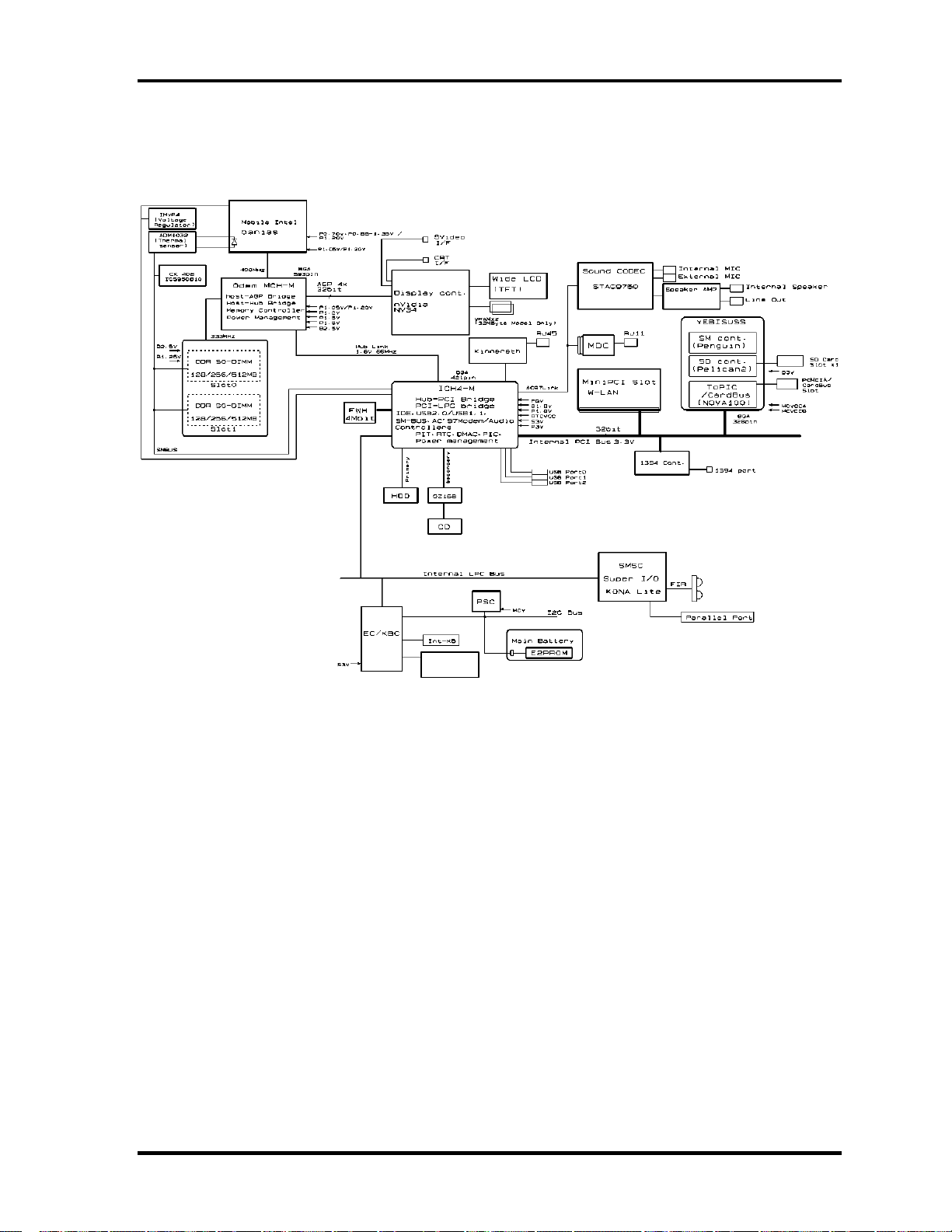
1.2 System Unit Block Diagram
Figure 1-3 is a block diagram of the system unit.
Internal
Touch Pad
Figure 1-3 System unit block diagram
Satellite M30-35 Maintenance Manual (960-455) 1-7
Page 22

1 Hardware Overview 1.2 System Unit Block Diagram
The system unit is composed of the following major components:
Processor
Intel Banias Processor 1.40GHz •
– Processor core speed: 1.40GHz (Performance Mode at 1.35V) and 1.20GHz
(Battery Optimized Mode at 0.85V)
– Processor bus speed: 400MHz
– Integrated L1 cache memory: 32KB instruction cache and 32KB write-back
data cache, 4-way set associative
– Integrated L2 cache memory: 1MB ECC protected cache data array, 8-way set
associative
– Integrated NDP
•
Intel Banias Processor 1.50GHz
– Processor core speed: 1.50GHz (Performance Mode at 1.35V) and 1.20GHz
(Battery Optimized Mode at 0.85V)
– Processor bus speed: 400MHz
– Integrated L1 cache memory: 32KB instruction cache and 32KB write-back
data cache, 4-way set associative
– Integrated L2 cache memory: 1MB ECC protected cache data array, 8-way set
associative
– Integrated NDP
•
Intel Banias Processor 1.60GHz
– Processor core speed: 1.60GHz (Performance Mode at 1.35V) and 1.20GHz
(Battery Optimized Mode at 0.85V)
– Processor bus speed: 400MHz
– Integrated L1 cache memory: 32KB instruction cache and 32KB write-back
data cache, 4-way set associative
– Integrated L2 cache memory: 1MB ECC protected cache data array, 8-way set
associative
– Integrated NDP
•
Intel Banias Processor 1.70GHz
– Processor core speed: 1.70GHz (Performance Mode at 1.35V) and 1.20GHz
(Battery Optimized Mode at 0.85V)
– Processor bus speed: 400MHz
– Integrated L1 cache memory: 32KB instruction cache and 32KB write-back
data cache, 4-way set associative
– Integrated L2 cache memory: 1MB ECC protected cache data array, 8-way set
associative
– Integrated NDP
1-8 Satellite M30-35 Maintenance Manual (960-455)
Page 23

1.2 System Unit Block Diagram 1 Hardware Overview
Memory
Two memory slots are provided. Expansion up to 2GB (2,048MB) is available.
Supports DDR CL2/2.5 •
•
Supports PC2700
– 256MB: 256Mbit (16M × 16bit) chips × 8
– 512MB: 512Mbit (32M × 8bit) chips × 16
– 512Mbit (32M × 16bit) chips × 8
– 1GB: 512Mbit (64M × 8 bit) chips × 16
•
200 pin, SO Dual In-line Memory Modules (SO-DIMM)
•
2.5 volt operation
Intel Odem+ (North Bridge)
•
One Intel RG82P4300M is used.
•
Features:
– Banias Processor System Bus Support
– DRAM Controller supporting DDR333/DDR266/DDR200, 1GB max
– Accelerated Graphics Port Interface: adheres to AGP2.0, AGP×4 mode
– Hub Link Interface
– 593-ball 37.5×37.5 mm FC-BGA package
Intel ICH4-M (South Bridge)
•
One Intel 82801LAM is used.
•
This gate array has the following features:
– Hub Link Interface
– PCI Rev2.2 Interface (6 PCI REQ/GNT Pairs)
– BusMaster IDE Controller (Ultra ATA 100/66/33)
– USB 1.1/2.0 Controller 6 Prots (EHCI: Enhanced Host Controller)
– I/O APIC (ACPI 1.06)
– SMBus2.0 Controller
– FWH Interface (BIOS)
– LPC Interface (EC/KBC, Super I/O)
– IRQ Controller
– Serial Interrupt Controller
– Power Management Controller
– Deeper Sleep (C4) Support
– Suspend/Resume Control
– AC'97 2.2 Interface
– Internal RTC
– Internal LAN Controller (WfM2.0)
– 421-ball 31×31mm BGA Package
Satellite M30-35 Maintenance Manual (960-455) 1-9
Page 24

1 Hardware Overview 1.2 System Unit Block Diagram
PC Card Controller Gate Array
One YEBISU-SS gate array is used. •
•
This gate array has the following functions and components.
– PCI interface (PCI Revision2.2)
– CardBus/PC Card controller (Yenta2 Version2.2)
– SD memory card controller (SDHC Ver.1.2)
– SD IO card controller (Ver.1.0)
– SmartMedia controller (SMHC Ver.01/SMIL1.0)
– SIO (UART) controller (MS Debug Port Specification Ver.1.0)
– Docking station interface
– Q switch control, reset control
– External device interface
Firmware Hub (FWH)
•
One Intel 82802AB8 is used.
•
This gate array has the following features:
– Intel platform compatibility
– Firmware hub hardware interface mode
– Industry-standard packages
– Two configurable interfaces
– 4Mbits of flash memory for platform code/data nonvolatile storage
– Address/Address-Multiplexed (A/A Mux) interface/mode
– Case temperature operating range
– Vcc: 3.3V ± 0.3V
– Vpp: 3.3V and 12V for fast programming (80 hours maximum)
– 4Mbits of flash memory are used as shown below:
– 64KB are used for VGA-BIOS.
– 192KB are used for system BIOS.
– 8KB are used for plug and play data area.
– 8KB are used for password security.
– 16KB are used for boot strap.
– 64KB are used for ACPI P code.
– 64KB are used for LOGO.
– 64KB are reserved for LAN BIOS.
– 32KB are reserved.
1-10 Satellite M30-35 Maintenance Manual (960-455)
Page 25

1.2 System Unit Block Diagram 1 Hardware Overview
GPU Controller
One nVIDIA NV34M chip is used. The GPU controller incorporates graphics accelerator,
video accelerator.
– VRAM 32MB (4M × 32 × 2)/64MB (4M × 32 × 4) DDR200MHz
– AGP bus R2.0 x 4
– LCD Interface LVDS 2ch
– TV Encoder: S-Video 4pin connectorTvxpress2
Sound Controller
AC-Link (in the South Bridge) and STAC975051T (Sigmatel made) are used.
Amplifier, Internal microphone, internal stereo speakers, stereo headphone
•
connector, external microphone connector and volume control knob are mounted.
EC/KBC (Embedded Controller/Keyboard Controller)
One Mitsubishi M306K9FCLRP micon chip functions as both EC and KBC.
•
EC
This controller controls the following functions:
– Power supply sequence
– Thermal conditions
– LEDs
– Beep
– Device ON/OFF
– Fan speed
– Universal I/O port
– Docker Docking Sequence
– Battery capacity check
– Forced reset
– Flash rewriting
– EC interface
– I2C communication
– EC access
– Slim Select Bay Control
•
KBC
This controller has the following functions:
– Scan controller to check status of keyboard matrix
– Interface controller between the keyboard scan controller and the system
– Control of switching and simultaneous operation of the accupoint/external
PS/2 mouse and of the internal keyboard/external PS/2 keyboard
PSC (Power Supply Controller)
Satellite M30-35 Maintenance Manual (960-455) 1-11
Page 26

1 Hardware Overview 1.2 System Unit Block Diagram
One TMP87PM48U chip is used. •
•
This controller controls the power sources.
Clock Generator
•
One ICS950812CGT is used.
•
This device generates the system clock.
Modem Controller
•
One built-in Askey-made 1456VQL4A(INT) modem card
•
This controller has the following functions:
– Digital line protection support
– Ring wake up support
– AC97 interface
– Supports V.92 56k Modem/Fax.
Internal LAN Controller
•
One Kinnereth-R (82562EP) chip is used.
– Supports 10/100Mbit Ethernet.
– Supports LED and WOL.
Wireless LAN
– Mini-PCI Type III 1slot
– Supports Kill SW.
– Supports Wireless LAN through PCMCIA
– 802.11b, 802.11a/b: Intel-made
– 802.11b/g, 802.11a/b/g: Atheros-made
Super I/O
•
One LPC 47N227 chip is used.
– This gate array has the following features:
– Floppy Disk Controller
– Serial Port Controller
– Infrared Communications Controller
– Parallel Port Controller
IEEE1394
•
One TSB43AB22 is used.
1-12 Satellite M30-35 Maintenance Manual (960-455)
Page 27

1.2 System Unit Block Diagram 1 Hardware Overview
Sensor
Thermal Sensor: One ADM1032AR chip is used. •
• LCD Sensor: One NRS-701-1015T is used.
Satellite M30-35 Maintenance Manual (960-455) 1-13
Page 28

1 Hardware Overview 1.3 3.5-inch Floppy Disk Drive (USB External)
1.3 3.5-inch Floppy Disk Drive (USB External)
The 3.5-inch USB FDD is a thin, high-performance reliable drive that supports 720KB and
1.44MB.
The FDD is shown in figure 1-4. The specifications for the FDD are listed in Table 1-1.
Figure 1-4 3.5-inch FDD (USB External)
Table 1-1 3.5-inch FDD specifications
Items 720KB mode 1.44MB mode
FDD part
rate
Disk rotation speed 300rpm 360rpm
Track density 5.3 track/mm (135TPI)
USB Full speed mode (12M bits/second)
250K bits/second
500K bits/second Data transfer
1-14 Satellite M30-35 Maintenance Manual (960-455)
Page 29
1.4 2.5-inch Hard Disk Drive 1 Hardware Overview
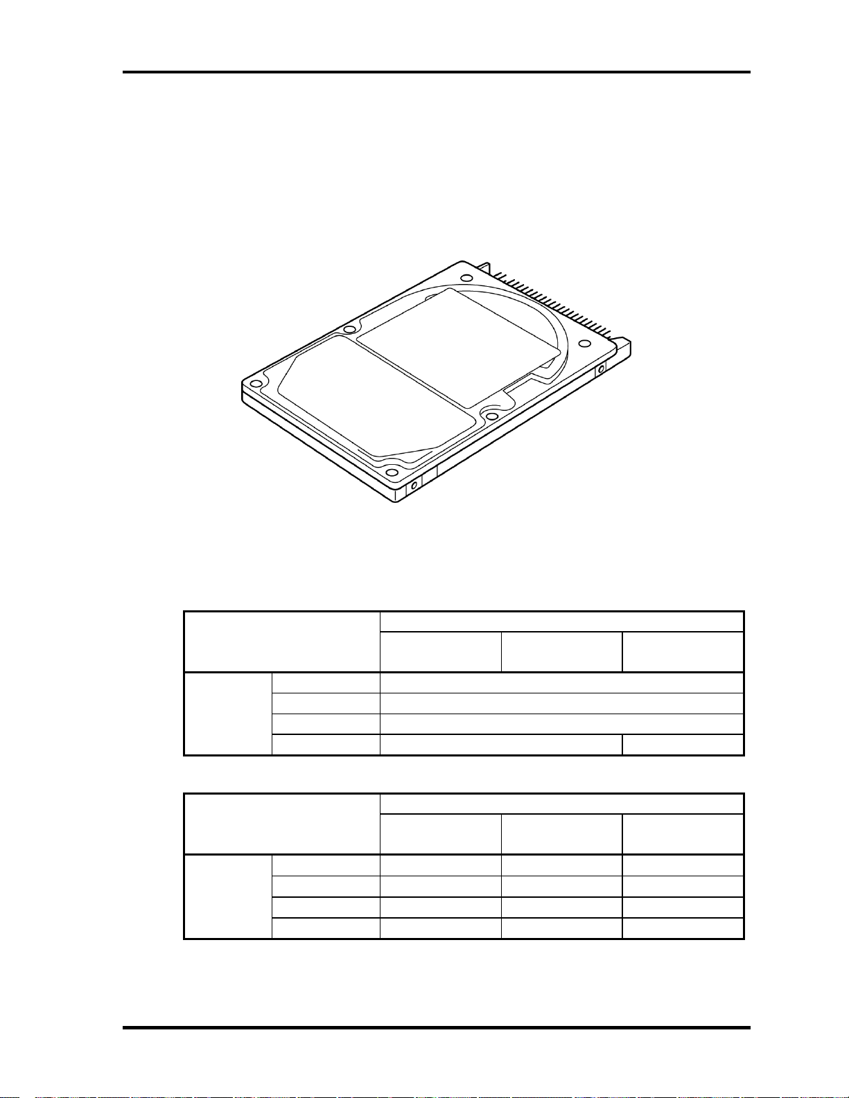
1.4 2.5-inch Hard Disk Drive
The removable HDD is a random access non-volatile storage device. It has a non-removable
2.5-inch magnetic disk and mini-Winchester type magnetic heads.
The computer supports a 40GB, 60GB and 80GB HDD.
The HDD is shown in figure 1-5. Specifications are listed in Table 1-2.
Figure 1-5 2.5-inch HDD
Table 1-2 2.5-inch HDD specifications (1/2)
Parameter Specifications
Outline Width (mm)
dimensions Height (mm)
Depth (mm)
Weight (g)
TOSHIBA
HDD2182B
99 max. 102 max.
TOSHIBA
HDD2183
69.85
9.5
100
TOSHIBA
HDD2184B
Parameter Specifications
Outline Width (mm)
dimensions Height (mm)
Depth (mm)
Weight (g)
HITACHI
G8C0000Z410
69.85±0.25 69.85±0.25
9.5±0.25 9.5±0.25 9.5±0.25
100±0.25 100±0.25 100±0.45
95 max. 99 max. 95 max.
HITACHI
G8C0000Z610
HITACHI
G8BC00013610
70 max
Satellite M30-35 Maintenance Manual (960-455) 1-15
Page 30
1 Hardware Overview 1.4 2.5-inch Hard Disk Drive
Parameter Specifications
Outline Width (mm)
dimensions Height (mm)
Depth (mm)
Weight (g)
HITACHI
GBC000Z810
69.85±0.25 69.85±0.25
9.5±0.25 9.5±0.25
100±0.25 100.2±0.25
99 max 102 99 max.
HITACHI
GBC000014810
TOSHIBA
HDD2188B
69.85
9.5
100
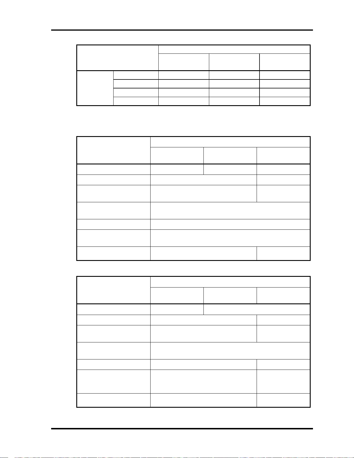
Table 1-2 2.5-inch HDD specifications(2/2)
Specifications
Parameter
Storage size (formatted) 40GB 60GB 60GB
Speed (RPM) 4200 5400
TOSHIBA
HDD2182B
TOSHIBA
HDD2183
TOSHIBA
HDD2184
Data transfer speed
(Mb/sec)
Interface transfer rate
(MB/s)
Track density (Ktpi) 78.9
Access Time
Average seek (sec)
Start time (sec)
154.3-298.0 202.9-373.3
100 max.
(Ultra DMA mode)
12
4 typ.
4 typ.
10 max.
Specifications
Parameter
Storage size (formatted) 40GB 60GB
Speed (RPM) 4200 5400
Data transfer speed
(Mb/sec)
Interface transfer rate
(MB/s)
HITACHI
G8C000Z410
HITACHI
G8C0000Z610
350 typ. 263.2-401.6
100 max.
(Ultra DMA mode)
HITACHI
G8BC00013610
Track density (Ktpi)
Access Time
Average seek (Read)
Average seek (Write)
Start time (sec)
96
12 typ.
14 typ.
5
(Power on)
85
13 typ.
-
5 typ
(Power on)
1-16 Satellite M30-35 Maintenance Manual (960-455)
Page 31

1.4 2.5-inch Hard Disk Drive 1 Hardware Overview
Specifications
Parameter
Storage size (formatted) 80GB 80GB
Speed (RPM) 4200 5400 4200
HITACHI
GBC000Z810
HITACHI
GBC00014810
TOSHIBA
HDD2188B
Data transfer speed
Interface transfer rate
(MB/s)
Track density (Ktpi) 96
Access Time (ms)
Average seek (Read)
Average seek (Write)
Start time (sec)
350 typ 450 max
12 typ
14 typ
5
(Power on)
100 max.
(Ultra DMA mode)
96
12 typ
14 typ
3.5
(Power on)
175.0-341.78
(Mbits/s)
88.1
12
-
4
Satellite M30-35 Maintenance Manual (960-455) 1-17
Page 32

1 Hardware Overview 1.5 CD-RW/DVD-ROM Drive
1.5 CD-RW/DVD-ROM Drive
This drive is a combination of DVD-ROM and CD-R/RW Drive. . It is full-size and runs
either 12cm (4.72-inch) or 8cm (3.15-inch) DVD/CDs without an adaptor. This drive reads
CD-ROM at maximum 24-speed, reads DVD-ROM at maximum 8-speed writes CD-R at
maximum 24-speed, and writes CD-RW at maximum 24-speed.
The CD-RW/DVD-ROM drive is shown in figure 1-6. Specifications are listed in Table 1-3.
Figure 1-6 CD-RW/DVD-ROM drive
Table 1-3 CD-RW/DVD-ROM drive specifications
Matushita G8CC0001C210
Item
ATAPI Burst (MB/s) 33.3 (Ultra DMA mode 2)
Average Access time (ms) 180 typ 130 typ
Data Buffer Capacity (MB) 2
Supported Format CD:
DVD-ROM mode CD-ROM mode CD-R/CD-RW
16.6 (PIO Mode 0 to 4, Multi word DMA mode 0 to 2)
CD-R, CD-RW
CD-DA, CD-ROM, CD-RW, CD-R, CDROM XA, Photo CD, Video CD,
CD-Extra, CD-text
DVD:
DVD-VIDEO, DVD-ROM, DVD-R (3.9G,
4.7G), DVD-RW, DVD-RAM (4.7G)
(Write)
1-18 Satellite M30-35 Maintenance Manual (960-455)
Page 33

1.6 DVD-R/RW 1 Hardware Overview
1.6 DVD-R/RW
A full-size DVD-R/-RW drive module lets you record data to rewritable CD/DVDs as well
as run either 12 cm (4.72") or 8 cm (3.15") CD/DVDs without using an adaptor. It reads
DVD-ROMs at maximum 8 speed, CD-ROMs at maximum 24 speed and CD-Rs at
maximum 16 speed. It writes CD-R at up to 16 speed, CD-RW at up to 10 speed, DVD-R
and DVD-RW at single speed.
The CD-RW/DVD-ROM drive is shown in figure 1-7. Specifications are listed in Table 1-4.
Figure 1-7 DVD-R/RW drive
Satellite M30-35 Maintenance Manual (960-455) 1-19
Page 34

1 Hardware Overview 1.6 DVD-R/RW
Table -4 DVD-R/RW drive specifications
Item
ATAPI Burst (MB/sec) 33.3 (Ultra DMA mode 2)
16.6 (PIO Mode 0 to 4, Multi word DMA
Average access time (ms)
DVD-ROM
CD-ROM
DVD-RAM
Data buffer (MB) 2
Speed (Read)
DVD-ROM
DVD-RAM
CD-ROM
Speed (Write)
CD-R
CD-RW
DVD-R
DVD-RW
Supported format (Read) CD:
CD-DA, CD+(E)G, CD-MIDI,
CD-TEXT, CD-ROM,
CD-ROM XA, CD-I,
CD-I Bridge (Photo-CD, Video-CD)
Multisession CD (Photo-CD,
CD-EXTRA, CD-R, CD-RW,
Portfolio),
CD-R, CD-RW
Toshiba
SD-R6112
mode 0 to 2)
115
105
170
8x
1x
24x
4x, 16x
4x,10x (High Speed)
1x, 2x
1x
DVD :
DVD-ROM (DVD-5, DVD-9,
DVD-10, DVD-18)
DVD-R (Ver.1.0, Ver.2.1)
DVD-RW(Ver.1.0, Ver.1.1)
DVD-RAM(Ver.2.1)
1-20 Satellite M30-35 Maintenance Manual (960-455)
Page 35

1.7 DVD-Multi (CD-R/RW DVD-RAM/R/RW) Drive 1 Hardware Overview
1.7 DVD-Multi (CD-R/RW DVD-RAM/R/RW) Drive
This drive is a combination of CD-R/RW, DVD-R/RW and DVD-RAM Drive. It is full-size
and runs either 12cm (4.72-inch) or 8cm (3.15-inch) DVD/CDs without an adaptor. This
drive reads CD-ROM at maximum 24-speed, reads DVD-ROM at maximum 8-speed writes
CD-R at maximum 16-speed, writes CD-RW at maximum 8-speed, writes DVD-R at
maximum 2-speed, writes DVD-RW at maximum 1-speed,.and writes DVD-RAM at
maximum 2-speed.
The DVD multi drive is shown in Figure 1-8. Specifications for the DVD multi drive are
described in table 1-5.
Figure 1-8 DVD-Multi drive
Table 1-5 DVD-Multi drive specifications (1/2)
Item
ATAPI Burst (MB/sec) 33.3 (Ultra DMA mode 2)
16.6 (PIO Mode 0 to 4, Multi word DMA mode 0 to 2)
Average access time (ms)
DVD-ROM
CD-ROM
Data buffer (MB) 2
Speed (Read)
DVD-ROM
DVD-Video
CD-ROM
CD-DA
DVD-RW
DVD-R/DVD-RW
TEAC
G8CC00013210
130 average.
110 average
8x (CAV)
4x (CAV)
24x (CAV)
8x (CLV)
4x (CAV)
4x (CAV)
Matsushita
G8CC00019210
180 typ. (Random)
150 typ. (Random)
8x max.
24x max. (CAV)
4
8
4
4
Satellite M30-35 Maintenance Manual (960-455) 1-21
Page 36

1 Hardware Overview 1.7 DVD-Multi (CD-R/RW DVD-RAM/R/RW) Drive
Table 1-5 DVD-Multi drive specifications (2/2)
Item
Speed (Write)
CD-R
CD-RW
DVD-R
DVD-RW
DVD-RAM
Supported format CD: CD-DA
CD-ROM
CD-ROM XA Mode 2
(Form 1, Form2)
Photo-CD
(single/multi-session)
Enhanced CD
CD-TEXT
DVD :DVD-ROM
DVD-R (General.
Authoring)
DVD-Video
DVD-RAM(4.7G,
2.6G)
TEAC
G8CC00013210
16x max.(ZCLV)
10x (CLV)
2x (CLV)
1x (CLV)
2x (ZLV)
Matsushita
G8CC00019210
16x (ZoneCLV)
2x (ZCLV) (4.7GB)
CD: CD-DA
CD-ROM
CD-R/W
CD-R
CD-ROMXA
CD-I Ready
Photo-CD
Video CD
Cd-Extra(CD+)
CD-TEXT
DVD :DVD-ROM
DVD-R (3.9GB,
4.7GB)
DVD-RW(Ver. 1.1)
DVD-RAM( 2.6G,
4.7GB,9.4GB)
8x (CLV)
2x (CLV)
1x (CLV)
1-22 Satellite M30-35 Maintenance Manual (960-455)
Page 37

1.8 Keyboard 1 Hardware Overview
1.8 Keyboard
The keyboard is mounted 85(US)/86(UK) keys that consist of character key and control key,
and in conformity with JIS. The keyboard is connected to membrane connector on the system
board and controlled by the keyboard controller.
Figure 1-9 is a view of the keyboard.
See Appendix E about a layout of the keyboard.
Figure 1-9 Keyboard
Satellite M30-35 Maintenance Manual (960-455) 1-23
Page 38

1 Hardware Overview 1.9 TFT Color Display
1.9 TFT Color Display
The TFT color display consists of 15.4-inch WXGA LCD module and FL inverter board.
1.9.1 LCD Module
A high-resolution external monitor connected to the computer can display up to
2048(H)×1536(V), at 16M colors.
Figure 1-10 shows a view of the LCD module and Table 1-6 lists the specifications.
Figure 1-10 LCD module
Table 1-6 LCD module specifications (1/5)
Item
15.4-inch WXGA (G33C0001D110)
Number of Dots 1,280 (W) x 800 (H)
Dot spacing (mm) 0.25875 (H) x 0.25875 (V)
Display range (mm) 331.2 (W) x 207(H)
Specifications
1-24 Satellite M30-35 Maintenance Manual (960-455)
Page 39

1.9 TFT Color Display 1 Hardware Overview
Table 1-6 LCD module specifications (2/5)
Item
15.4-inch WXGA (G33C0001F110)
Number of Dots 1,280 (W) x 800 (H)
Dot spacing (mm) 0.25875 (H) x 0.25875 (V)
Display range (mm) 332.16(H) x 207.6(V)
Specifications
Table 1-6 LCD module specifications (3/5)
Item
15.4-inch WXGA (G33C0001H110)
Number of Dots 1,280 (W) x 800 (H)
Dot spacing (mm) 0.2595 (H) x 0.2595 (V)
Display range (mm) 332.16 (W) x 207.6 (H)
Specifications
Table 1-6 LCD module specifications (4/5)
Item
15.4-inch WXGA(CSV) (G33C0001E110)
Number of Dots 1,280 (W) x 800 (H)
Dot spacing (mm) 0.25875 (H) x 0.25875 (V)
Display range (mm) 331.2 (W) x 207 (H)
Specifications
Table 1-6 LCD module specifications (5/5)
Item
15.4-inch WXGA(CSV) (G33C0001G110)
Number of Dots 1,280 (W) x 800 (H)
Dot spacing (mm) 0.25875 (H) x 0.25875 (V)
Display range (mm) 331.2 (W) x 207 (H)
Specifications
Satellite M30-35 Maintenance Manual (960-455) 1-25
Page 40

1 Hardware Overview 1.9 TFT Color Display
1.9.2 FL Inverter Board
The FL inverter board supplies a high frequency current to illuminate the LCD module FL.
Table 1-7 lists the FL inverter board specifications.
Table 1-7 FL inverter board specifications
Item Specifications
Voltage (V) DC 5 Input
Power (W) 7
Output
Voltage (V) 750
Current (mA) 6.00
Power (mA) 5W/7VA
1-26 Satellite M30-35 Maintenance Manual (960-455)
Page 41

1.10 Power Supply 1 Hardware Overview
1.10 Power Supply
The power supply supplies many different voltages to the system board and performs the
following functions:
1. Checks power input to determine:
Whether the AC adaptor is connected to the computer •
•
Whether the battery pack is installed and supplying power
2. Checks power supply’s internal controls:
•
Battery pack charging: start, stop and voltage supplied to the battery pack
•
Power supply system: Power supplied from a DC power source (AC adaptor)
•
Faulty power supply: Executes forced shutdown if needed
•
Logic: Power supply to various circuits
•
Charging current to PWM control IC for battery pack charging
3. Controls the following aspects of the logic system
•
Power supply to gate arrays
•
Power on/off
4. Indicates the following:
•
DC IN (sets LED to orange or blue)
•
Battery icon (sets LED to orange or blue)
•
Faulty power supply by low battery
5. Interface for the following:
•
BIOS via EC/KBC
•
Function mode of power supply
6. Detects the following:
•
Input voltage to logic system
•
Input voltage, overvoltage and input/output to battery pack
•
Battery pack’s internal temperature
•
Input voltage to DC power supply (output from AC adaptor)
The power supply output rating is specified in Table 1-8.
Satellite M30-35 Maintenance Manual (960-455) 1-27
Page 42

1 Hardware Overview 1.10 Power Supply
Table 1-8 Power supply output rating (1/2)
Name Voltage (V) Use
PPV
MCH1R2-
P1V
PTV 1.075 CPU, ADM1032, Odem, ICH4-M
2R5-B2V 2.5 Odem, SDRAM
2R5-P2V 2.5 NV34
1R25-B1V 1.25 SDRAM
PGV 1.2-1.5 NV34
LAN-E3V 3.3 ICH4-M, KINNERETH
S3V 3.3 ICH4-M, EC/KBC
B3V 3.3 YEBISU3S, PC Card ,MDC
P3V 3.3
SD-P3V 3.3 SD
E5V 5 USB
CD-E5V 5 CD-ROM
B5V 5 PC Card
1.468-0.748
1.2 Odem
CPU
Clock Generator, ICH4-M, FWH, mini-PCI, Super I/O,FIR,
IEEE 1394, LCD, STAC9750
P5V 5 HDD, KB,LED, Parallel, LCD
SND-E5V 5 AN12940
1R8-P1V 1.8 Odem, ICH4-M
1R5-P1V 1.5 Odem, ICH4-M, NV34
1R5-S1V 1.5 ICH4-M
LAN1R5-
E1V
1.5 ICH4-M
1-28 Satellite M30-35 Maintenance Manual (960-455)
Page 43

1.10 Power Supply 1 Hardware Overview
Table 1-8 Power supply board output rating (2/2)
Name Voltage (V) Use
S5V 5 OZ168
MCV 5 PSC
A4R7-P4V 4.7
CDA4R7-E4V 4.7
R3V 2.0-3.3 ICH4-M
STAC9750, MIC
CD, Headphone
Satellite M30-35 Maintenance Manual (960-455) 1-29
Page 44

1 Hardware Overview 1.11 Batteries
1.11 Batteries
The computer has three types of batteries as follows:
Main battery pack
RTC battery
The battery specifications are listed in Table 1-9.
Table 1-9 Battery specifications
Battery name Material Output voltage Capacity
Main battery Lithium-Ion (6-cell) 10.8 V 4,400mAh
Lithium-Ion (12 cell) 10.8 V 8,800mAh
RTC battery Nickel-metal hydride 2.4 V 16
1.11.1 Main Battery
The removable main battery pack is the computer’s main power source when the AC adaptor
is not attached. The main battery maintains the state of the computer when the computer
enters in resume mode.
1-30 Satellite M30-35 Maintenance Manual (960-455)
Page 45

1.11 Batteries 1 Hardware Overview
1.11.2 Battery Charging Control
Battery charging is controlled by a power supply microprocessor. The microprocessor
controls whether the charge is on or off and detects a full charge when the AC adaptor and
battery are attached to the computer. The system charges the battery using quick charge.
Quick Battery Charge
When the AC adaptor is attached, there are two types of quick charge: quick charge 1 when
the system is powered off and quick charge 2 when the system is powered on.
Table 1-10 Time required for quick charges
Status Charging time
Quick charge 1
(Power off)
(Power on)
12 cell About 3.4 hours
6 cell About 2.7 hours
12 cell About 8.0 to 20.0 or longer Quick charge 2
6 cell About 4.0 to 10.0 or longer
NOTE: The time required for quick charge 2 is affected by the amount of power the system
is consuming. Use of the fluorescent lamp and frequent disk access diverts power and
lengthens the charge time.
If any of the following occurs, the battery quick charge process stops.
1. The battery becomes fully charged.
2. The AC adaptor or battery is removed.
3. The battery or output voltage is abnormal.
Detection of full charge
A full charge is detected only when the battery is charging at quick charge. A full charge is
detected under any of the following conditions:
1. The current in the battery charging circuit drops under the predetermined limit.
2. The charging time exceeds the fixed limit.
Satellite M30-35 Maintenance Manual (960-455) 1-31
Page 46

1 Hardware Overview 1.11 Batteries
1.11.3 RTC battery
The RTC battery provides power to keep the current date, time and other setup information
in memory while the computer is turned off. Table 1-11 lists the charging time and data
preservation period of the RTC battery.
Table 1-11 RTC battery charging/data preservation time
Status Time
Charging Time (power on) 8 hours
Data preservation period (full charge) 1 month
1-32 Satellite M30-35 Maintenance Manual (960-455)
Page 47

Chapter 2
Troubleshooting Procedures
Page 48

2 Troubleshooting Procedures
2-ii Satellite M30-35 Maintenance Manual (960-455)
Page 49

2 Troubleshooting Procedures
Chapter 2 Contents
2.1 Troubleshooting......................................................................................................... 2-1
2.2 Troubleshooting Flowchart ....................................................................................... 2-2
2.3 Power Supply Troubleshooting ................................................................................. 2-6
Procedure 1 Power LED Check ...................................................................... 2-6
Procedure 2 Error Code Check ....................................................................... 2-8
Procedure 3 Connection Check ..................................................................... 2-14
Procedure 4 Charge Check ............................................................................ 2-15
Procedure 5 Replacement Check................................................................... 2-16
2.4 System Board Troubleshooting ............................................................................... 2-17
Procedure 1 Message Check ......................................................................... 2-18
Procedure 2 Debugging Port Check on Boot Mode ...................................... 2-20
Procedure 3 Diagnostic Test Program Execution Check .............................. 2-28
Procedure 4 Replacement Check................................................................... 2-29
2.5 FDD Troubleshooting.............................................................................................. 2-30
Procedure 1 FDD Head Cleaning Check....................................................... 2-30
Procedure 2 Diagnostic Test Program Execution Check .............................. 2-31
Procedure 3 Connector Check and Replacement Check ............................... 2-32
2.6 HDD Troubleshooting ............................................................................................. 2-33
Procedure 1 Message Check ......................................................................... 2-33
Procedure 2 Partition Check.......................................................................... 2-34
Procedure 3 Format Check ............................................................................ 2-35
Procedure 4 Diagnostic Test Program Execution Check .............................. 2-36
Procedure 5 Connector Check and Replacement Check ............................... 2-37
2.7 Keyboard Troubleshooting...................................................................................... 2-38
Procedure 1 Diagnostic Test Program Execution Check .............................. 2-38
Procedure 2 Connector and Replacement Check .......................................... 2-39
2.8 Display Troubleshooting ......................................................................................... 2-40
Satellite M30-35 Maintenance Manual (960-455) 2-iii
Page 50

2 Troubleshooting Procedures
Procedure 1 External Monitor Check............................................................ 2-40
Procedure 2 Diagnostic Test Program Execution Check .............................. 2-40
Procedure 3 Connector and Cable Check...................................................... 2-41
Procedure 4 Replacement Check................................................................... 2-42
2.9 Optical Drive Troubleshooting................................................................................ 2-43
Procedure 1 Diagnostic Test Program Execution Check .............................. 2-43
Procedure 2 Connector Check and Replacement Check ............................... 2-44
2.10 Modem Troubleshooting ......................................................................................... 2-45
Procedure 1 Diagnostic Test Program Execution Check .............................. 2-45
Procedure 2 Connector Check and Replacement Check ............................... 2-46
2.11 LAN Troubleshooting ............................................................................................. 2-47
Procedure 1 Diagnostic Test Program Execution Check .............................. 2-47
Procedure 2 Connector Check and Replacement Check ............................... 2-47
2.12 Wireless LAN Troubleshooting .............................................................................. 2-48
Procedure 1 Transmitting-Receiving Check ................................................. 2-48
Procedure 2 Antennas' Connection Check .................................................... 2-49
Procedure 3 Antenna Check.......................................................................... 2-50
Procedure 4 Replacement Check................................................................... 2-51
2.13 Sound Troubleshooting ........................................................................................... 2-52
Procedure 1 Diagnostic Test Program Execution Check .............................. 2-52
Procedure 2 Connector Check....................................................................... 2-53
Procedure 3 Replacement Check................................................................... 2-54
2.14 SD Card SlotTroubleshooting ................................................................................. 2-55
Procedure 1 Check on Windows ................................................................... 2-55
Procedure 2 Connector/Replacement Check................................................ 2-55
2-iv Satellite M30-35 Maintenance Manual (960-455)
Page 51

2 Troubleshooting Procedures
Figures
Figure 2-1 Troubleshooting flowchart ............................................................................ 2-3
Figure 2-2 A set of tool for debug port test ................................................................... 2-20
Figure 2-3 Antenna test cable ....................................................................................... 2-50
Tables
Table 2-1 Battery Icon ................................................................................................... 2-6
Table 2-2 DC IN icon .................................................................................................... 2-7
Table 2-3 Error code ...................................................................................................... 2-9
Table 2-4 Debugging port boot mode status ................................................................ 2-21
Table 2-5 FDD error code and status ........................................................................... 2-31
Table 2-6 Hard disk drive error code and status .......................................................... 2-36
Satellite M30-35 Maintenance Manual (960-455) 2-v
Page 52

2 Troubleshooting Procedures
2-vi Satellite M30-35 Maintenance Manual (960-455)
Page 53

2.1 Troubleshooting 2 Troubleshooting Procedures
2
2.1 Troubleshooting
Chapter 2 describes how to determine if a Field Replaceable Unit (FRU) in the computer is
causing the computer to malfunction. The FRUs covered are:
1. Power supply 5. Keyboard 9. LAN
2. System Board 6. Display 10. Wireless LAN
3. Floppy Disk Drive 7. Optical Drive 11. Sound components
4. Hard Disk Drive 8. Modem 12. SD Card Slot
The Diagnostics Disk operations are described in Chapter 3. Detailed Replacement
Procedures are given in Chapter 4, Replacement Procedures.
The following tools are necessary for implementing the troubleshooting procedures:
1. Diagnostics Disk
2. Phillips screwdriver (2 mm)
3. LH-STIX screwdriver (in some models)
4. Toshiba MS-DOS system disk(s)
(You must install the following onto the disk: SYS.COM, FORMAT.COM,
FDISK.COM and FDISK.EXE)
5. Formatted work disk for floppy disk drive testing
6. Cleaning kit for floppy disk drive troubleshooting
7. Parallel port wraparound connector
8. PC card wraparound connector
9. Multimeter
10. External USB FDD
11. External USB keyboard and Mouse
12. Headphone
13. Microphone
14. USB test module and USB cable
15. TOSHIBA CD-ROM TEST DISK (ZA1217P01/P000204190)
16. CD-RW Media (RICOH-made x4 recommended)
17. DVD-ROM TSD-1 (TOSHIBA-EMI DVD Test Media)
18. Music CD
19. RJ11 connector checker
20. Speaker
21. Personal computer that can communicate by wireless LAN for wireless LAN
troubleshooting
22. Antenna test cable
Satellite M30-35 Maintenance Manual (960-455) 2-1
Page 54

2 Troubleshooting Procedures 2.2 Troubleshooting Flowchart
2.2 Troubleshooting Flowchart
Use the flowchart in Figure 2-1 as a guide for determining which troubleshooting procedures
to execute. Before going through the flowchart steps, verify the following:
Ask the user if a password is registered and, if it is, ask him or her to enter the
password. If the user has forgotten the system password, perform the following
procedure at the appropriate step in the flowchart in Figure 2-1:
Verify with the customer that Toshiba Windows is installed on the hard disk. Non-
Windows operating systems can cause the computer to malfunction.
Make sure all optional equipment is removed from the computer.
Make sure the External USB floppy disk drive is empty.
2-2 Satellite M30-35 Maintenance Manual (960-455)
Page 55

2.2 Troubleshooting Flowchart 2 Troubleshooting Procedures
Figure 2-1 Troubleshooting flowchart (1/2)
Satellite M30-35 Maintenance Manual (960-455) 2-3
Page 56

2 Troubleshooting Procedures 2.2 Troubleshooting Flowchart
Figure 2-1 Troubleshooting flowchart (2/2)
2-4 Satellite M30-35 Maintenance Manual (960-455)
Page 57

2.2 Troubleshooting Flowchart 2 Troubleshooting Procedures
If the diagnostics program cannot detect an error, the problem may be intermittent. The
Running Test program should be executed several times to isolate the problem. Check the
Log Utilities function to confirm which diagnostic test detected an error, then perform the
appropriate troubleshooting procedures as follows:
1. If an error is detected on the system test, memory test, real timer test, perform the
System Board and Processor Module Troubleshooting Procedures in Section 2.4.
2. If an error is detected on the floppy disk test, perform the FDD Troubleshooting
Procedures in Section 2.5.
3. If an error is detected on the hard disk test, perform the HDD Troubleshooting
Procedures in Section 2.6.
4. If an error is detected on the keyboard test, perform the Keyboard Troubleshooting
Procedures in Section 2.7.
5. If an error is detected on the display test, perform the Display Troubleshooting
Procedures in Section 2.8.
6. If an error is detected on the Optical Drive test, perform the Optical Drive
Troubleshooting Procedures in Section 2.9.
7. If an error is detected on the modem test, perform the Modem Troubleshooting
Procedures in Section 2.10.
8. If an error is detected on the LAN test, perform the LAN Troubleshooting Procedures
in Section 2.11.
9. If an error is detected on the Wireless LAN test, perform the Wireless LAN
Troubleshooting Procedures in Section 2.12.
10. If an error is detected on the sound test, perform the Sound Troubleshooting
Procedures in Section 2.13.
11. If an error is detected on the SD card test, perform the SD card slot Troubleshooting
Procedures in Section 2.14.
Satellite M30-35 Maintenance Manual (960-455) 2-5
Page 58

2 Troubleshooting Procedures 2.3 Power Supply Troubleshooting
2.3 Power Supply Troubleshooting
The power supply controls many functions and components. To determine if the power
supply is functioning properly, start with Procedure 1 and continue with the other Procedures
as instructed. The procedures described in this section are:
Procedure 1: Icon Check
Procedure 2: Error Code Check
Procedure 3: Connection Check
Procedure 4: Charge Check
Procedure 5: Replacement Check
Procedure 1 Icon Check
The following Icons indicate the power supply status:
Battery icon
DC IN icon
The power supply controller displays the power supply status through the Battery icon and
the DC IN icon as listed in the tables below. To check the power supply status, install a
battery pack and connect an AC adapter.
Table 2-1 Battery Icon
Battery LED Power supply status
Lights orange Quick charge
Lights blue Battery is fully charged and AC adapter is connected.
Blinks orange
(even intervals)
Flashes orange The power switch is pressed on when the battery level is low.*2
Doesn’t light Any condition other than those above
The battery level becomes low while operating the computer on battery
power.*1
*1 Low Battery Hibernation will be executed soon.
*2 Low Battery Hibernation has already been executed.
2-6 Satellite M30-35 Maintenance Manual (960-455)
Page 59

2.3 Power Supply Troubleshooting 2 Troubleshooting Procedures
Table 2-2 DC IN icon
DC IN icon Power supply status
Lights blue DC power is being supplied from the AC adapter.
Blinks orange Power supply malfunction*3
Doesn’t light Any condition other than those above
*3 When the power supply controller detects a malfunction, the DC IN LED
blinks and an error code is displayed.
If the icon blinks, execute the followings:
1. Remove the battery and AC adapter to cut power supply to the computer.
2. Reinstall the battery and AC adapter.
If the LED still blinks, perform the followings:
Check 1 If the DC IN icon blinks orange, go to Procedure 2.
Check 2 If the DC IN icon does not light blue, go to Procedure 3.
Check 3 If the battery icon does not light orange or blue, go to Procedure 4.
Satellite M30-35 Maintenance Manual (960-455) 2-7
Page 60

2 Troubleshooting Procedures 2.3 Power Supply Troubleshooting
Procedure 2 Error Code Check
If the power supply microprocessor detects a malfunction, the DC IN icon blinks orange. The
blink pattern indicates an error as shown below.
Start Off for 2 seconds
Error code (8 bit)
“1” On for one second
“0” On for a half second
Interval between data bits Off for a half second
The error code begins with the least significant digit.
Example: Error code = 12h (Error codes are given in hexadecimal format.)
2-8 Satellite M30-35 Maintenance Manual (960-455)
Page 61

2.3 Power Supply Troubleshooting 2 Troubleshooting Procedures
Check 1 Convert the DC IN icon blink pattern into the hexadecimal error code and
compare it to the tables below.
The error code begins with the least significant digit.
Error code
Table 2-3 Error code
Error code Where Error occurs
1*h DC Power (AC Adapter)
2*h The 1st battery
4*h S3V output (3.3V)
5*h 1R5-C1V output (1.51V)
6*h 1R8-C1V output (1.804V)
7*h PPV output (CPU core voltage)
8*h 1R2-P1V output (1.21V)
9*h E5V output (5.0V)
A*h E3V output (3.3V)
B*h 2R5-P2V output (for VGA: 2.51V)
C*h PGV output (for VGA core: 1.20V)
D*h 1R25-P1V output (1.251V)
E*h 2R5-B2V output (2.51V)
Satellite M30-35 Maintenance Manual (960-455) 2-9
Page 62

2 Troubleshooting Procedures 2.3 Power Supply Troubleshooting
Check 1 Compare the patterns in the hexadecimal error code to the tables below.
DC IN
Error code Meaning
10h AC Adaptor output voltage is over 16.5 V.
11h Advanced Port Replicator output voltage is over 16.5 V.
12h Current from the DC power supply is over the limit (7.00 A).
13h Current from the DC power supply is over the limit (0.5 A), when there
is no load.
14h Current sensing IC is not normal, when there is no load.
Main Battery
Error code Meaning
20h Over voltage has been detected.
21h Main battery charge current is over 7.00 A.
S3V output
Error code Meaning
1R5-C1V output
Error code Meaning
22h Main battery discharge current is over 0.5 A, when there is no load.
23h Main battery charge current is over 4.3 A, when the AC adapter is not
directly connected.
24h Current sensing IC is not normal, when there is no load.
25h Main battery charge current is over 0.3 A.
40h S3V voltage is 3.14 V or under, when the computer is powered on/off.
45h S3V voltage is 3.14 V or under at power on.
50h 1R5-C1V voltage is over 1.80 V, when the computer is powered on/off.
51h 1R5-C1V voltage is 1.275V or under, when the computer is powered
on.
52h 1R5-C1V voltage is 1.275V or under, when the computer is booting up.
53h 1R5-C1V voltage is 1.275V or under, when the computer is
suspended.
54h 1R5-C1V voltage is not normal, when the computer is suspended.
55h 1R5-C1V voltage is 1.275V or under at power on.
2-10 Satellite M30-35 Maintenance Manual (960-455)
Page 63

2.3 Power Supply Troubleshooting 2 Troubleshooting Procedures
1R8-C1V output
Error code Meaning
60h 1R8-C1V voltage is over 2.16 V, when the computer is powered on/off.
61h 1R8-C1V voltage is 1.53 V or under, when the computer is powered
on.
62h 1R8-C1V voltage is 1.53 V or under, when the computer is booting up.
63h 1R8-C1V voltage is 1.53 V or under, when the computer is suspended.
64h 1R8-C1V voltage is not normal, when the computer is suspended.
65h 1R8-C1V voltage is 1.53V or under at power on.
PPV output
Error code Meaning
70h PPV voltage is over 1.80 V, when the computer is powered on/off.
71h PPV voltage is 0.56 V or under, when the computer is powered on.
1R2-P1V output
Error code Meaning
E5V output
Error code Meaning
72h PPV voltage is 0.56 V or under, when the computer is booting up.
73h PPV voltage is 0.56 V or over, when the computer is powered off.
80h 1R2-P1V voltage is over 1.44 V, when the computer is powered on/off.
81h 1R2-P1V voltage is 1.02 V or under, when the computer is powered
on.
82h 1R2-P1V voltage is 1.02 V or under, when the computer is booting up.
83h 1R2-P1V voltage is 1.02 V or over, when the computer is powered off.
84h 1R2-P1V voltage is 1.02 V or under, when the computer is suspended.
90h E5V voltage is over 6.00V, when the computer is powered on/off.
91h E5V voltage is 4.50 V or under, when the computer is powered on.
92h E5V voltage is 4.50 V or under, when the computer is booting up.
93h E5V voltage is 4.50 V or over, when the computer is powered off.
94h E5V voltage is 4.50 V or under, when the computer is suspended.
Satellite M30-35 Maintenance Manual (960-455) 2-11
Page 64

2 Troubleshooting Procedures 2.3 Power Supply Troubleshooting
E3V output
Error code Meaning
A0h E3V voltage is over 3.96 V, when the computer is powered on/off.
A1h E3V voltage is 2.81 V or under, when the computer is powered on.
A2h E3V voltage is 2 .81 V or under, when the computer is booting up.
A3h E3V voltage is 2.81 V or over, when the computer is powered off.
A4h E3V voltage is 2.81 V or under when the computer is suspended.
2R5-P2V output
Error code Meaning
B0h 2R5-P2V voltage is over 3.00 V, when the computer is powered on/off.
B1h 2R5-P2V voltage is 2.125 V or under, when the computer is powered
on.
B2h 2R5-P2V voltage is 2.125 V or under, when the computer is booting
up.
PGV output
B3h 2R5-P2V voltage is 2.125 V or over, when the computer is powered
off.
Error code Meaning
C0h PGV voltage is over 1.62V, when the computer is powered on/off.
C1h PGV voltage is 2.125 V or under, when the computer is powered on.
C2h PGV voltage is 2.125 V or under, when the computer is booting up.
C3h PGV voltage is 2.125 V or over, when the computer is powered off.
C4h PGV voltage is 2.125 V or under when the computer is suspended.
2-12 Satellite M30-35 Maintenance Manual (960-455)
Page 65

2.3 Power Supply Troubleshooting 2 Troubleshooting Procedures
1R25-P1V output
Error code Meaning
D0h 1R25-P1V voltage is over 1.50 V, when the computer is powered
on/off.
D1h 1R25-P1V voltage is 1.063 V or under, when the computer is powered
on.
D2h 1R25-P1V voltage 1.063 V or under, when the computer is booting up.
D3h 1R25-P1V voltage is 1.063 V or over, when the computer is powered
off.
D4h 1R25-P1V voltage is 1.063 V or under, when the computer is
suspended.
2R5-B2V output
Error code Meaning
E0h 2R5-B2V voltage is over 3.00 V, when the computer is powered on/off.
E1h 2R5-B2V voltage is 2.125 V or under, when the computer is powered
on.
E2h 2R5-B2V voltage is 2.125V or under, when the computer is booting up.
E3h 2R5-B2V voltage is 2.125 V or over, when the computer is powered
off.
E4h 2R5-B2V voltage is 2.125 V or under when the computer is
suspended.
Check 2 In the case of error code 10h or 12h:
Make sure the AC adaptor cord and AC power cord are firmly plugged into
the DC IN 15 V socket and wall outlet. If the cables are connected correctly,
go to the following step:
Connect a new AC adaptor and/or AC power cord, if necessary. If the error
still exists, go to Procedure 5.
Check 3 In the case of error code 2Xh:
Make sure the battery pack is correctly installed in the computer. If the battery
pack is correctly installed, go to the following step:
Replace the battery pack with a new one. If the error still exists, go to
Procedure 5.
Check 4 For any other error, go to Procedure 5.
Satellite M30-35 Maintenance Manual (960-455) 2-13
Page 66

2 Troubleshooting Procedures 2.3 Power Supply Troubleshooting
Procedure 3 Connection Check
The power supply wiring diagram is shown below:
Any of the connectors may be disconnected. Perform Check 1.
Check 1 Disconnect the AC power cord from the wall outlet. Check the power cable for
breaks. If the power cord is damaged, connect a new AC power cord. If there is no
damage, go to Check 2.
Check 2 Make sure the AC adaptor cord and AC power cord are firmly plugged into the
PJ8800 DC IN 15 V socket and AC adaptor inlet/wall outlet, respectively. If these
cables are connected correctly, go to Check 3.
Check 3 Make sure the DC IN input port where an AC adaptor’s DC output plug is
connected is firmly secured to the system board.
• If the DC IN input port is loose, go to Procedure 5.
• If it is not loose, go to Check 4.
Check 4 Use a multimeter to make sure the AC adaptor output voltage is close to 15 V. If
the output is several percent lower than 15 V, go to Check 5. If the output is close
to 15 V, go to Check 6.
Check 5 Connect a new AC adaptor or AC power cord.
• If the DC IN icon does not light, go to Procedure 5.
• If the battery icon does not light, go to Check 6.
Check 6 Make sure the battery pack is installed in the computer correctly. If the battery is
properly installed and the battery icon still does not light, go to Procedure 4.
2-14 Satellite M30-35 Maintenance Manual (960-455)
Page 67

2.3 Power Supply Troubleshooting 2 Troubleshooting Procedures
Procedure 4 Charge Check
The power supply may not charge the battery pack. Perform the following procedures:
1. Reinstall the battery pack.
2. Attach the AC adaptor and turn on the power. If you cannot turn on the power, go to
Procedure 5.
3. Run the Diagnostic test, go to System test and execute subtest 06 (Quick charge)
described in Chapter 3.
4. When charge is complete, the diagnostics test displays the result code. Check the
result code against the table below and perform any necessary check.
Result code Contents Check items
0 The battery is charging normally. Normal
1 The battery is fully charged. Normal
2 The AC adaptor is not connected. Check 1
3 The AC adaptor’s output voltage is not normal. Check 1
4 The battery is not installed. Check 2
5 The battery’s output voltage is not normal. Check 3
6 The battery’s temperature is not normal. Check 4
7 A bad battery is installed. Check 2
8 Any other problems. Check 5
Check 1 Make sure the AC adaptor and AC power cord are firmly plugged into the DC IN
socket and the wall outlet. If these cables are connected correctly, replace the AC
adaptor (and/or AC power cord, if necessary).
Check 2 Make sure the battery is properly installed. If the battery is properly installed, go
to Check 3.
Check 3 The battery pack may be completely discharged. Wait a few minutes to charge the
battery pack. If the battery pack is still not charged, go to Check 4.
Check 4 The battery’s temperature is too hot or cold. Return the temperature to a normal
operating condition. If the battery pack still is not charged, go to Check 5.
Check 5 Replace the battery pack with a new one. If the battery pack still is not charged,
go to Procedure 5.
Satellite M30-35 Maintenance Manual (960-455) 2-15
Page 68

2 Troubleshooting Procedures 2.3 Power Supply Troubleshooting
Procedure 5 Replacement Check
The system board processor module may be disconnected or damaged. Disassemble the
computer following the steps described in Chapter 4, Replacement Procedures. Check the
connection between the AC adaptor and system board. After checking the connections,
perform the following Check 1:
Check 1 Replace the AC adaptor with a new one. If the AC adaptor still does not function
properly, perform Check 2.
Check 2 Replace the system board with a new one following the steps described in Chapter
4, Replacement Procedures.
2-16 Satellite M30-35 Maintenance Manual (960-455)
Page 69

2.4 System Board Troubleshooting 2 Troubleshooting Procedures
2.4 System Board Troubleshooting
This section describes how to determine if the system board is defective or not. Start with
Procedure 1 and continue with the other procedures as instructed. The procedures described
in this section are:
Procedure 1: Message Check
Procedure 2: Debugging port status Check
Procedure 3: Diagnostic Test Program Execution Check
Procedure 4: Replacement Check
Satellite M30-35 Maintenance Manual (960-455) 2-17
Page 70

2 Troubleshooting Procedures 2.4 System Board Troubleshooting
Procedure 1 Message Check
When the power is turned on, the system performs the Initial Reliability Test (IRT) installed
in the BIOS ROM. The IRT tests each IC on the system board and initializes it.
If an error message is shown on the display, perform Check 1.
If nothing is displayed, go to Procedure 2.
If an operating system is properly loaded, go to Procedure 4.
Check 1 If one of the following error messages displays on the screen, press the Run
Setup key as the message instructs. These errors occur, when the system
configuration preserved in the RTC memory (CMOS type memory) is not the
same as the actual configuration or when the data is lost.
If you press the Run Setup key as the message instructs, the SETUP screen
appears to set the system configuration. If any error message is displayed, perform
Check 2.
If error message (a) appears often when the power is turned on, replace the RTC
battery. If any other error message displays, perform Check 2.
(a) 0250: RTC battery is low
(b) 0251: CMOS checksum is inconsistent
(c) 0271: Check date and time settings
(d) 0290: ROM data is invalid
Check 2 If the following error message appears on the screen, press the Continue key as
the message instructs. This error occurs, when consumption of battery or failure
of system board loses the resumed data. Go to Procedure 3.
WARNING: RESUME FAILURE.
If any other error message displays, perform Check 3.
2-18 Satellite M30-35 Maintenance Manual (960-455)
Page 71

2.4 System Board Troubleshooting 2 Troubleshooting Procedures
Check 3 The IRT checks the system board. When the IRT detects an error, the system
stops or an error message appears.
If error message (5) appears, go to the Keyboard Troubleshooting Procedures in
Section 2.7.
If error message (1), (2), (3) or (4) appears, go to the HDD Troubleshooting
Procedures in Section 2.6.
If error message (7) appears, go to the FDD Troubleshooting Procedures in
Section 2.5.
(1) 0201: Failure IDE#0
(2) 0202: Failure IDE#1
(3) 0203: Failure IDE#2
(4) 0204: Failure IDE#3
(5) 0212: Keyboard Controller Failed
(6) 0260: System timer error
(7) 02B0: Diskette drive A error
Satellite M30-35 Maintenance Manual (960-455) 2-19
Page 72

2 Troubleshooting Procedures 2.4 System Board Troubleshooting
Procedure 2 Debugging Port Check on Boot Mode
Check the D port status by a debug port test. The tool for debug port test is shown below.
Figure 2-2 A set of tool for debug port test
The test procedures are follows;
1. Connect the debug test cable to the connector PJ2000 of the system board. For
disassembling to connect the test cable, refer to Chapter 4.
2. Connect the debug port test cable and RS-232C cross-cable to the test board.
3. Connect the RS-232C cross-cable to the PC that displays the results.
System board
4. Boot the computer in MS-DOS mode.
2-20 Satellite M30-35 Maintenance Manual (960-455)
Page 73

2.4 System Board Troubleshooting 2 Troubleshooting Procedures
5. Execute GETDPORT.COM in the text menu in CPU REAL mode. (Insert the FD for
starting D port into FDD and input “FD starting drive:>dport”.)
The D port status is displayed in the following form;
6. When the D port status is FFFFh (normal status), go to Procedure 3.
7. When the D port status falls into any status in Table 2-4, execute Check 1.
Table 2-4 Debugging port boot mode status (1/7)
Debug Port Description
0000h
0080h Initialize the chipset
0081h Initialize the bridge
0082h Initialize the CPU
0083h Initialize system timer
0084h Initialize system I/O
0085h Check for BIOS changing
0087h Go to BIOS
0088h Initialize Multi Processor
0089h Set segments to 4GB
008Ah Initialize specific HW
008Bh Initialize PIC and DMA
008Ch Initialize Memory type
008Dh Initialize Memory size
008Eh Shadow Boot Block
0090h System memory test
0091h Initialize interrupt vectors
0094h Output one beep
0095h Initialize the boot device
0096h Reset segments to 64KB
0097h Boot BIOS change utility
Satellite M30-35 Maintenance Manual (960-455) 2-21
Page 74

2 Troubleshooting Procedures 2.4 System Board Troubleshooting
Table 2-4 Debugging port boot mode status (2/7)
Debug Port Description
0098h Initialize USB Controller
0101h
0102h Verify Real Mode. If the CPU is in protected mode, turn on A20 and pulse the
reset line, forcing a shutdown 0.
0103h Disable Non-Maskable Interrupts.
0104h Get CPU type from CPU registers and save it.
0106h Initialize system hardware. Reset the DMA controllers, disable the videos, clear
any pending interrupts from the real-time clock and set up port B register.
0107h Disable system ROM shadow and start to execute ROM code from the flash part.
0108h Initialize chip set registers to the initial values.
0109h Set in-POST flag in CMOS that indicates we are in POST.
010Ah Initialize CPU registers.
010Bh
010Ch Initialize cache.
010Eh
010Fh
0110h
0111h Load alternate registers with initial table values
0112h Restore the contents of the CPU control word whenever the CPU is reset.
0113h Reset PCI devices in early post
0114h
0116h Verify that the ROM BIOS checksums to zero
0117h Initialize external cache before autosizing memory.
0118h Initialize PIT(Programmable Interval Timer).
011Ah Initialize DMA.
011Ch Initialize interrupt controllers for some shutdowns.
011Fh
0120h Verify that DRAM refresh is operating by polling the refresh bit in PORTB.
0122h
0124h Set segment-register addressibility to 4 GB
0128h Determine DRAM size and configure the chipset accordingly. Before autosizing,
all caches and all shadow RAM are disabled.
2-22 Satellite M30-35 Maintenance Manual (960-455)
Page 75

2.4 System Board Troubleshooting 2 Troubleshooting Procedures
Table 2-4 Debugging port boot mode status (3/7)
Debug Port Description
0129h Initialize the POST Memory Manager
012Ah Zero clear the first 512K of RAM
012Bh
012Ch Test 512K base address lines
012Eh Test the first 4MB of RAM.
012Fh Initialize external cache before shadowing.
0132h Compute CPU speed.
0133h Initialize the Phoenix Dispatch Manager
0134h Test the CMOS RAM and RTC
0136h Vector to proper shutdown routine.
0138h Shadow the system BIOS.
013Ah External cache is autosized and its configuration saved in memory.
013Bh
013Ch If CMOS is valid, load chipset registers with values from CMOS, otherwise load
defaults.
013Dh Load alternate registers with CMOS values.
013Fh
0141h
0142h Initialize interrupt vectors 0 thru 77h to the BIOS general interrupt handler.
0145h Initialize all motherboard devices.
0146h Verify the ROM copyright notice
0148h Verify that the equipment specified in the CMOS matches the hardware currently
installed.
0149h Initialize all PCI devices.
014Ah Initialize video chip in system
014Bh
014Ch Shadow video BIOS ROM.
014Eh Display copyright notice.
014Fh Initialize MultiBoot. Allocate memory for old and new MultiBoot history tables.
0150h Display CPU type and speed.
0151h
Satellite M30-35 Maintenance Manual (960-455) 2-23
Page 76

2 Troubleshooting Procedures 2.4 System Board Troubleshooting
0152h
Table 2-4 Debugging port boot mode status (4/7)
Debug Port Description
0154h
0155h
0157h
0158h Test for unexpected interrupts.
0159h Initialize the POST display service.
015Ah Display prompt "Press F2 for SETUP"
015Bh Disable L1 cache during POST
015Ch Test RAM between 512K and 640K.
0160h Determine the amount of extended memory available.
0162h
0164h
0166h
0167h
0168h
0169h Initialize the handler for SMM.
016Ah
016Ch Display shadow message.
0170h Display error messages on the screen.
0172h Check status bits to see if configuration problems were detected. If so, Display
error messages on the screen.
0176h
017Ch Initialize the hardware interrupt vectors from 08 to 0F and from 70h to 77H. Also
set the interrupt vectors from 60h to 66H to zero.
017Dh
017Eh The Coprocessor initialization test.
0180h
0181h Run late device initialization routines.
0182h
0183h Configure Fisk Disk Controller.
0184h
2-24 Satellite M30-35 Maintenance Manual (960-455)
Page 77

2.4 System Board Troubleshooting 2 Troubleshooting Procedures
0185h Configure all PnP ISA devices.
0186h
Table 2-4 Debugging port boot mode status (5/7)
Debug Port Description
0187h Configure motherboard configurable devices.
0188h Initialize timeouts, key buffer, and soft reset flag.
0189h Enable non-maskable interrupts.
018Ah Initialize Extended BIOS Data Area and initialize the mouse.
018Bh
018Ch Initialize the floppy disk and display an error message if failure was detected.
018Fh
0190h Initialize hard-disk controller.
0191h Configure the local bus IDE timing register based on the drives attached to it.
0192h
0193h
0195h Initialize CD-ROM drive.
0196h Reset segment-register addressibility from 4GB to normal 64K by generating a
Shutdown 8.
0197h
0198h Search for option ROMs.
0199h Check support status for Self-Monitoring Analysis Reporting Technology (disk-
failure warning).
019Bh
019Ch Perform late SMM initialization.
019Dh Initialize Security Engine.
019Eh Enable hardware interrupts.
019Fh
01A0h Verify that the system clock is interrupting.
01A2h Setup Numlock indicator.
01A4h
01A8h Remove "Press F2" prompt from the screen.
01AAh
01ACh Enter SETUP.
Satellite M30-35 Maintenance Manual (960-455) 2-25
Page 78

2 Troubleshooting Procedures 2.4 System Board Troubleshooting
01AEh Clear CMOS flags for post.
2-26 Satellite M30-35 Maintenance Manual (960-455)
Page 79

2.4 System Board Troubleshooting 2 Troubleshooting Procedures
Table 2-4 Debugging port boot mode status (6/7)
Debug Port Description
01B0h Check for errors.
01B1h
01B2h Change status bits in CMOS and/or the BIOS data area to reflect the fact that
POST is complete.
01B3h
01B5h Fade out logo screen.
01B6h
01B7h Initialize ACPI BIOS.
01B9h Clear all screen graphics before booting.
01BAh Initialize the SMBIOS header and sub-structures.
01BCh Clear parity-error latch
01BDh
01BEh Clear the screen before booting.
01BFh
01C1h Initialize error handler
01C2h Save the current boot type into CMOS
01C3h Check the requested boot type
01C4h Initializes (clears) the system error flags
01C5h Mark the fact that we are no longer in POST
01C6h
01C7h
01C8h
01C9h Check (and do) if BIOS change is necessary
01CAh
01CBh
01CCh Restore the memory configuration.
01CDh
01CEh
01D1h Initialize BIOS stack area
01D3h Clear memory
01D4h Determines if the CPU supports the Extended CPUID function for Processor
Name/Brand String.
01D6h
Satellite M30-35 Maintenance Manual (960-455) 2-27
Page 80

2 Troubleshooting Procedures 2.4 System Board Troubleshooting
Table 2-4 Debugging port boot mode status (7/7)
Debug Port Description
01D7h
01D8h
20FFh Try to boot with INT 19h.
03B0h
05B1h
05B2h
05B3h
05B4h
05B5h
06BFh
2-28 Satellite M30-35 Maintenance Manual (960-455)
Page 81

2.4 System Board Troubleshooting 2 Troubleshooting Procedures
Procedure 3 Diagnostic Test Program Execution Check
Execute the following tests from the Diagnostic Test Menu. Refer to Chapter 3, Tests and
Diagnostics, for more information on how to perform these tests.
1. System test
2. Memory test
3. Keyboard test
4. Display test
5. Floppy Disk test
6. Printer test
7. Async test
8. Hard Disk test
9. Real Timer test
10. NDP test
11. Expansion test
12. CD-ROM/DVD-ROM test
13. Wireless LAN test
14. Sound/LAN/Modem test
15. IEEE1394
If an error is detected during these tests, go to Procedure 4.
Satellite M30-35 Maintenance Manual (960-455) 2-29
Page 82

2 Troubleshooting Procedures 2.4 System Board Troubleshooting
Procedure 4 Replacement Check
The system board connectors may be disconnected. Disassemble the computer following the
steps described in Chapter 4, Replacement Procedures and perform Check 1.
Check 1 Visually check for the following:
a) Cracked or broken connector housing
b) Damaged connector pins
If connectors are in good condition, but there is still a problem, go to Check 2.
Check 2 The system board may be damaged. Replace the system board with a new one
following the steps described in Chapter 4, Replacement Procedures.
2-30 Satellite M30-35 Maintenance Manual (960-455)
Page 83

2.5 FDD Troubleshooting 2 Troubleshooting Procedures
2.5 FDD Troubleshooting
This section describes how to determine if the FDD is functioning properly. Perform the
steps below starting with Procedure 1 and continuing with the other procedures as required.
Procedure 1: FDD Head Cleaning Check
Procedure 2: Diagnostic Test Program Execution Check
Procedure 3: Connector Check and Replacement Check
Procedure 1 FDD Head Cleaning Check
FDD head cleaning operation details are given in Chapter 3, Tests and Diagnostics.
Insert the Diagnostics Disk in the computer’s floppy disk drive, turn on the computer and run
the test. Clean the FDD heads using the cleaning kit. If the FDD still does not function
properly after cleaning, go to Procedure 2.
If the test program cannot be executed, go to Procedure 3.
Satellite M30-35 Maintenance Manual (960-455) 2-31
Page 84

2 Troubleshooting Procedures 2.5 FDD Troubleshooting
Procedure 2 Diagnostic Test Program Execution Check
Insert the Diagnostics Disk in the FDD, turn on the computer and run the test. Refer to
Chapter 3, Tests and Diagnostics, for more information about the diagnostics test procedures.
Floppy disk drive test error codes and their status names are listed in Table 2-5. Make sure
the floppy disk is formatted correctly and that the write protect tab is disabled. If any other
errors occur while executing the FDD diagnostics test, go to Check 1.
Table 2-5 FDD error code and status
Code Status
01h Bad command
02h Address mark not found
03h Write protected
04h Record not found
06h Media removed on dual attach card
08h DMA overrun error
09h DMA boundary error
10h CRC error
20h FDC error
40h Seek error
60h No FDD
80h Time out error (Not ready)
EEh Write buffer error
FFh Data compare error
Check 1 If the following message displays, release the write protect tab on the floppy disk.
If any other message appears, perform Check 2.
FDD-Write protected
Check 2 Make sure the floppy disk is formatted correctly. If it is, go to Procedure 3.
2-32 Satellite M30-35 Maintenance Manual (960-455)
Page 85

2.5 FDD Troubleshooting 2 Troubleshooting Procedures
Procedure 3 Connector Check and Replacement Check
The 3.5inch FDD is connected to the System Board via USB port.
Check 1 Make sure the USB cable is securely connected to the FDD. Also, make sure the
USB cable of the FDD is securely connected to the system board.
If any of the connections are loose, reconnect firmly and repeat Procedure 2.
If any connector is damaged, replace it with a new one and repeat Procedure 2.
If there is still an error, go to Check 2.
Check 2 The FDD cable may be defective or damaged. Replace it with a new one. If the
FDD is still not functioning properly, perform Check 3.
Check 3 Replace the System board with a new one following the steps in Chapter 4,
Replacement Procedures.
Satellite M30-35 Maintenance Manual (960-455) 2-33
Page 86

2 Troubleshooting Procedures 2.6 HDD Troubleshooting
2.6 HDD Troubleshooting
This section describes how to determine if the HDD is functioning properly. Perform the
steps below starting with Procedure 1 and continuing with the other procedures as required.
Procedure 1: Message Check
Procedure 2: Partition Check
Procedure 3: Format Check
Procedure 4: Diagnostic Test Program Execution Check
Procedure 5: Connector Check and Replacement Check
CAUTION: The contents of the hard disk will be erased when you execute the HDD
troubleshooting procedures. Transfer the contents of the hard disk to floppy
disks or other storage media.
Procedure 1 Message Check
When the computer’s HDD does not function properly, some of the following error messages
may appear on the display. Start with Check 1 below and perform the other checks as
instructed.
Check 1 If any of the following messages appear, go to Procedure 5. If the following
messages do not appear, perform Check 2.
HDC ERROR (After 5 seconds this message will disappear.)
or
IDE #0 ERROR (After 5 seconds this message will disappear.)
or
IDE #1 ERROR (After 5 seconds this message will disappear.)
Check 2 If either of the following messages appears, go to Procedure 2. If the following
messages do not appear, perform Check 3.
Insert system disk in drive
Press any key when ready .....
or
Non-System disk or disk error
Replace and press any key
Check 3 Make sure the Hard Disk option is set to not used. If it is set to not used, choose
another setting and restart the computer. If the problem still exists, go to
Procedure 2.
2-34 Satellite M30-35 Maintenance Manual (960-455)
Page 87

2.6 HDD Troubleshooting 2 Troubleshooting Procedures
Procedure 2 Partition Check
Insert the Toshiba MS-DOS system disk and restart the computer with U key holding down.
Perform the following checks:
Check 1 Type C: and press Enter. If you cannot change to drive C, go to Check 2. If you
can change to drive C, go to Check 3.
Check 2 Type FDISK and press Enter. Choose Display Partition Information from the
FDISK menu. If drive C is listed, go to Check 3. If drive C is not listed, return to
the FDISK menu and choose the option to create a DOS partition on drive C.
Restart the computer from the Toshiba MS-DOS system disk. If the problem still
exists, go to Procedure 3.
Check 3 If drive C is listed as active in the FDISK menu, go to Check 4. If drive C is not
listed as active, return to the FDISK menu and choose the option to set the active
partition for drive C. Restart the computer and then go to Procedure 3.
Check 4 Remove the FD and restart the computer. If the problem still exists, go to
Procedure 3.
Satellite M30-35 Maintenance Manual (960-455) 2-35
Page 88

2 Troubleshooting Procedures 2.6 HDD Troubleshooting
Procedure 3 Format Check
The computer’s HDD is formatted using the low level format program and the MS-DOS
FORMAT program. To format the HDD, start with Check 1 below and perform the other
steps as required.
Check 1 Format the HDD and transfer system files using FORMAT C:/S/U. If the
following message appears on the display, the HDD is formatted.
Format complete
If an error message appears on the display, refer to the Toshiba MS-DOS Manual
for more information and perform Check 2.
Check 2 Using the Diagnostics Disk, format the HDD with a low level format option.
Refer to Chapter 3, Tests and Diagnostics for more information about the
diagnostic program.
If the following message appears on the display, the HDD low level format is
complete. Partition and format the HDD using the MS-DOS FORMAT command.
Format complete
If you cannot format the HDD using the Tests and Diagnostic program, go to
Procedure 4.
2-36 Satellite M30-35 Maintenance Manual (960-455)
Page 89

2.6 HDD Troubleshooting 2 Troubleshooting Procedures
Procedure 4 Diagnostic Test Program Execution Check
The HDD test program is stored in the Diagnostics Disk. Perform all of the HDD tests in the
Hard Disk Drive Test. Refer to Chapter 3, Tests and Diagnostics, for more information about
the HDD test program.
If an error is detected during the HDD test, an error code and status will be displayed.
Replace the HDD with a new one following the instructions in Chapter 4, Replacement
Procedures. The error codes and statuses are listed in Table 2-6. If an error code is not
generated and the problem still exists, go to Procedure 5.
Table 2-6 Hard disk drive error code and status
Code Status
01h Bad command
02h Bad address mark
04h Record not found
05h HDC not reset
07h Drive not initialized
08h HDC overrun (DRQ)
09h DMA boundary error
0Ah Bad sector error
0Bh Bad track error
10h ECC error
11h ECC recover enable
20h HDC error
40h Seek error
80h Time out error
AAh Drive not ready
BBh Undefined error
CCh Write fault
E0h Status error
EEh Access time out error
DAh No HDD
Satellite M30-35 Maintenance Manual (960-455) 2-37
Page 90

2 Troubleshooting Procedures 2.6 HDD Troubleshooting
Procedure 5 Connector Check and Replacement Check
The HDD may be disconnected, or the HDD or the system board may be damaged.
Disassemble the computer following the steps described in Chapter 4, Replacement
Procedures and perform the following checks:
Check 1 Make sure the HDD is firmly connected to the system board.
If the connection is loose, reconnect firmly and repeat Procedure 1. If there is still
an error, go to Check 2.
Check 2 The HDD may be damaged. Replace it with a new one following the instructions
in Chapter 4, Replacement Procedures. If the problem still exists, perform Check
3.
Check 3 The system board may be damaged. Replace it with a new one following the
instructions in Chapter 4, Replacement Procedures.
2-38 Satellite M30-35 Maintenance Manual (960-455)
Page 91

2.7 Keyboard Troubleshooting 2 Troubleshooting Procedures
2.7 Keyboard Troubleshooting
To determine if the computer’s keyboard is functioning properly, perform the following
procedures. Start with Procedure 1 and continue with the other procedures as instructed.
Procedure 1: Diagnostic Test Program Execution Check
Procedure 2: Connector and Replacement Check
Procedure 1 Diagnostic Test Program Execution Check
Execute the Keyboard Test in the Diagnostic Program. Refer to Chapter 3, Tests and
Diagnostics, for more information on how to perform the test program.
If an error occurs, go to Procedure 2. If an error does not occur, the keyboard is functioning
properly.
Satellite M30-35 Maintenance Manual (960-455) 2-39
Page 92

2 Troubleshooting Procedures 2.7 Keyboard Troubleshooting
Procedure 2 Connector and Replacement Check
The keyboard, PAD I/F and PAD Switch may be disconnected or damaged. Disassemble the
computer following the steps described in Chapter 4, Replacement Procedures, and perform
the following checks:
1. If the keyboard malfunctions, start with Check 1.
2. If the PAD switch malfunctions, start with Check 3.
Check 1 Make sure the keyboard cable is securely connected to the system board.
If the connection is loose, reconnect firmly and repeat Procedure 1. If there is still
an error, go to Check 2.
Check 2 The keyboard or its cable may be damaged. Replace it with a new one following
the instructions in Chapter 4, Replacement Procedures. If the problem still exists,
perform Check 5.
Check 3 Make sure the PAD switch cable is firmly connected to the system board.
If the connection is loose, reconnect firmly and repeat Procedure 2. If there is still
an error, go to Check 4.
Check 4 The PAD switch board or PAD switch cable may be damaged. Replace it with a
new one following the instructions in Chapter 4, Replacement Procedures. If the
problem still exists, perform Check 5.
Check 5 The system board may be damaged. Replace it with a new one following the
instructions in Chapter 4, Replacement Procedures.
2-40 Satellite M30-35 Maintenance Manual (960-455)
Page 93

2.8 Display Troubleshooting 2 Troubleshooting Procedures
2.8 Display Troubleshooting
This section describes how to determine if the computer’s display is functioning properly.
Start with Procedure 1 and continue with the other procedures as instructed.
Procedure 1: External Monitor Check
Procedure 2: Diagnostic Test Program Execution Check
Procedure 3: Connector and Cable Check
Procedure 4: Replacement Check
Procedure 1 External Monitor Check
Connect an external monitor to the computer’s external monitor port, then boot the computer.
The computer automatically detects the external monitor.
If the external monitor works correctly, the internal LCD may be damaged. Go to Procedure
3.
If the external monitor appears to have the same problem as the internal monitor, the system
board may be damaged. Go to Procedure 2.
Procedure 2 Diagnostic Test Program Execution Check
The Display Test program is stored on the computer’s Diagnostics disk. This program checks
the display controller on the system board. Insert the Diagnostics disk in the computer’s
floppy disk drive, turn on the computer and run the test. Refer to Chapter 3, Tests and
Diagnostics for details. If an error is detected, go to Procedure 3.
Satellite M30-35 Maintenance Manual (960-455) 2-41
Page 94

2 Troubleshooting Procedures 2.8 Display Troubleshooting
Procedure 3 Connector and Cable Check
The LCD Module is connected to the system board by an LCD/FL cable. The FL inverter
board is also connected to the system board by an LCD/FL cable. And the FL is connected to
the FL inverter board by the HV cable. The connectors may be disconnected from the system
board or the FL inverter board, or they may be damaged. Disassemble the computer
following the steps described in Chapter 4, Replacement Procedures.
If the connection is loose, reconnect firmly and restart the computer. If there is still an error,
go to Procedure 4.
2-42 Satellite M30-35 Maintenance Manual (960-455)
Page 95

2.8 Display Troubleshooting 2 Troubleshooting Procedures
Procedure 4 Replacement Check
The FL, FL inverter board, LCD module, and system board are connected to display circuits.
Any of these components may be damaged. Refer to Chapter 4, Replacement Procedures, for
instructions on how to disassemble the computer and then perform the following checks:
If the FL does not light, perform Check 1.
If characters or graphics are not displayed clearly, perform Check 4.
If some screen functions do not operate properly, perform Check 4.
If the FL remains lit when the display is closed, perform Check 5.
Check 1 Replace the FL with a new one following the instructions in Chapter 4,
Replacement Procedures and test the display again. If the problem still exists,
perform Check2.
Check 2 The LCD/FL cable or HV cable may be defective or damaged. Replace the
FL/LCD or HV cable with a new one following the instructions in Chapter 4,
Replacement Procedure and test the display again. If the problem still exists,
perform Check3.
Check 3 The FL inverter board may be defective or damaged. Replace the FL inverter
board with a new one following the instructions in Chapter 4, Replacement
Procedure and test the display again. If the problem still exists, perform Check4.
Check 4 The LCD module may be defective or damaged. Replace the LCD module with a
new one following the instructions in Chapter 4, Replacement Procedure and test
the display again. If the problem still exists, perform Check 5.
Check 5 The system board may be defective or damaged. Replace it with a new one
following the instructions in Chapter 4, Replacement Procedure.
Satellite M30-35 Maintenance Manual (960-455) 2-43
Page 96

2 Troubleshooting Procedures 2.9 Optical Drive Troubleshooting
2.9 Optical Drive Troubleshooting
This section describes how to determine if the Optical Drive is functioning properly. Perform
the steps below starting with Procedure 1 and continue with the other procedures as required.
Procedure 1: Diagnostic Test Program Execution Check
Procedure 2: Connector Check and Replacement Check
Procedure 1 Diagnostic Test Program Execution Check
The CD-ROM/DVD-ROM test program is stored in the Diagnostics Disk.
For the test, prepare a test CD-ROM, DVD-ROM, music CD and CD-RW Media.
Then insert the Diagnostics Disk in the computer’s floppy disk drive, turn on the computer
and run the test. Refer to Chapter 3, Tests and Diagnostics, for more information about the
diagnostics test procedures.
If any errors occur while executing the CD-ROM/DVD-ROM test, go to Procedure 2.
2-44 Satellite M30-35 Maintenance Manual (960-455)
Page 97

2.9 Optical Drive Troubleshooting 2 Troubleshooting Procedures
Procedure 2 Connector Check and Replacement Check
The Optical Drive is connected to the system board. The connectors may be disconnected
from the system board or may be damaged. Disassemble the computer following the steps
described in Chapter 4, Replacement Procedures and perform the following checks:
Check 1 Make sure the Optical Drive is firmly connected to the system board.
If the connection is loose, reconnect firmly and repeat Procedure 1. If there is still
an error, go to Check 2.
Check 2 The Optical Drive may be defective or damaged. Replace the drive with a new
one. If there is still an error, go to Check 3.
Check 3 Replace the system board with a new one following the steps in Chapter 4,
Replacement Procedures.
Satellite M30-35 Maintenance Manual (960-455) 2-45
Page 98

2 Troubleshooting Procedures 2.10 Modem Troubleshooting
2.10 Modem Troubleshooting
This section describes how to determine if the computer's modem is functioning properly.
Perform the steps below starting with Procedure 1 and continuing with the other procedures
as required.
Procedure 1: Diagnostic Test Program Execution Check
Procedure 2: Connector Check and Replacement Check
Procedure 1 Diagnostic Test Program Execution Check
The Sound/LAN/Modem test program is stored in the Diagnostics Disk.
For the test, prepare a test Sound/LAN/Modem.
Then insert the Diagnostics Disk in the computer’s floppy disk drive, turn on the computer
and run the test. Refer to Chapter 3, Tests and Diagnostics, for more information about the
diagnostics test procedures.
If any errors occur while executing the Sound/LAN/Modem test, go to Procedure 2.
2-46 Satellite M30-35 Maintenance Manual (960-455)
Page 99

2.10 Modem Troubleshooting 2 Troubleshooting Procedures
Procedure 2 Connector Check and Replacement Check
The Modem is installed as a modem daughter card (MDC). If the modem malfunctions, there
may be a bad connection between the MDC and the System Board. Or the MDC, System
Board or their connectors might be damaged.
Disassemble the computer following the steps described in Chapter 4, Replacement
Procedures and perform the following checks:
Check 1 Make sure the MDC cable is firmly connected to the MDC and make sure the
MDC is firmly connected to PJ3000 on the System Board.
MDC cable
If a connector is disconnected, connect it firmly and repeat Procedure 1. If the
Modem is still not functioning properly, perform Check 2.
Check 2 The MDC may be defective or damaged. Replace it with a new one following the
steps in Chapter 4, Replacement Procedures. If the Modem is still not functioning
properly, perform Check 3.
Check 3 The system board may be defective or damaged. Replace the System Board with a
new one following the steps in Chapter 4, Replacement Procedures.
Satellite M30-35 Maintenance Manual (960-455) 2-47
Page 100

2 Troubleshooting Procedures 2.12 LAN Troubleshooting
2.11 LAN Troubleshooting
This section describes how to determine if the computer's LAN is functioning properly.
Perform the steps below starting with Procedure 1 and continuing with the other procedures
as required.
Procedure 1: Diagnostic Test Program Execution Check
Procedure 2: Connector Check and Replacement Check
Procedure 1 Diagnostic Test Program Execution Check
The Sound/LAN/Modem test program is stored in the Diagnostics Disk.
For the test, prepare a test Sound/LAN/Modem.
Then insert the Diagnostics Disk in the computer’s floppy disk drive, turn on the computer
and run the test. Refer to Chapter 3, Tests and Diagnostics, for more information about the
diagnostics test procedures.
If any errors occur while executing the Sound/LAN/Modem test, go to Procedure 2.
Procedure 2 Connector Check and Replacement Check
A RJ45 jack with LAN cable is on the System Board. If the LAN malfunctions, the System
Board might be damaged.
Disassemble the computer following the steps described in Chapter 4, Replacement
Procedures.
2-48 Satellite M30-35 Maintenance Manual (960-455)
 Loading...