

Page 1
4 Replacement Procedures 4.14 Speakers
4
4.14 Speakers
Removing the Speakers
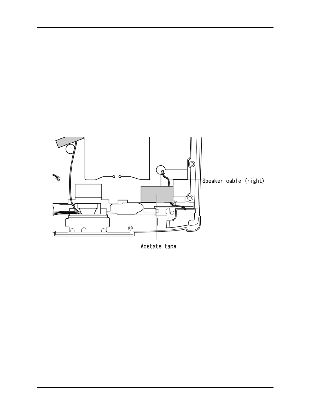
To remove the speakers, follow the steps below and refer to figure 4-33, 4-34.
1. Seat the top cover and display assembly.
2. Remove the acetate tape fixing the speaker cable (right) on the back.
Figure 4-33 Removing the glass tape
4-52 PORTEGE M100 Maintenance Manual (960-452)
Page 2
4.14 Speakers 4 Replacement Procedures
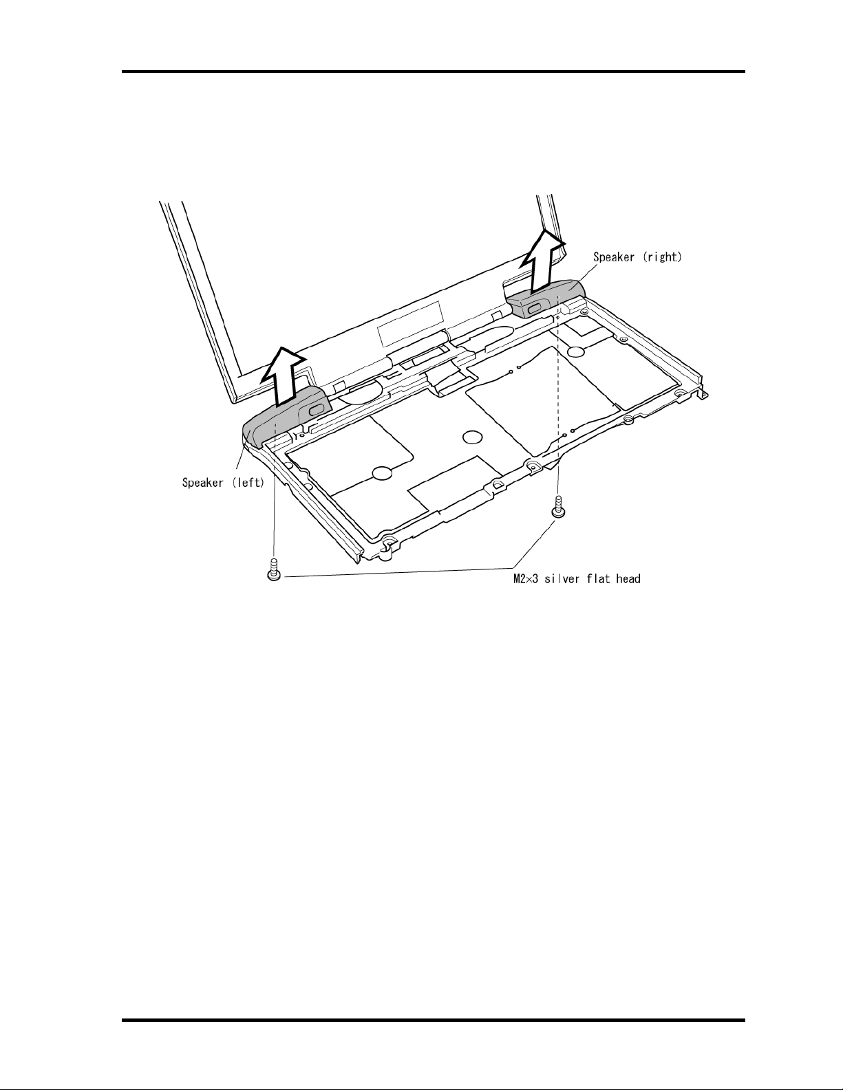
3. Remove two M2x3 silver flat head screws.
4. Grasp the speakers and lift up to remove it.
Figure 4-34 Removing Speakers
PORTEGE M100 Maintenance Manual (960-452) 4-53
Page 3

4 Replacement Procedures 4.14 Speakers
Installing the Speakers
To install the speakers, follow the steps below and refer to figure 4-33, 4-34.
1. Pass each speaker cable through the hole and seat each speaker.
2. Secure each speaker with a M2x3 silver flat head screw.
3. Fix the speaker cable (right) with an acetate tape on the back.
4-54 PORTEGE M100 Maintenance Manual (960-452)
Page 4
4.15 System Board 4 Replacement Procedures
4.15 System Board
Removing the System Board
To remove the system board, follow the steps below and refer to figures 4-35 and 4-36.
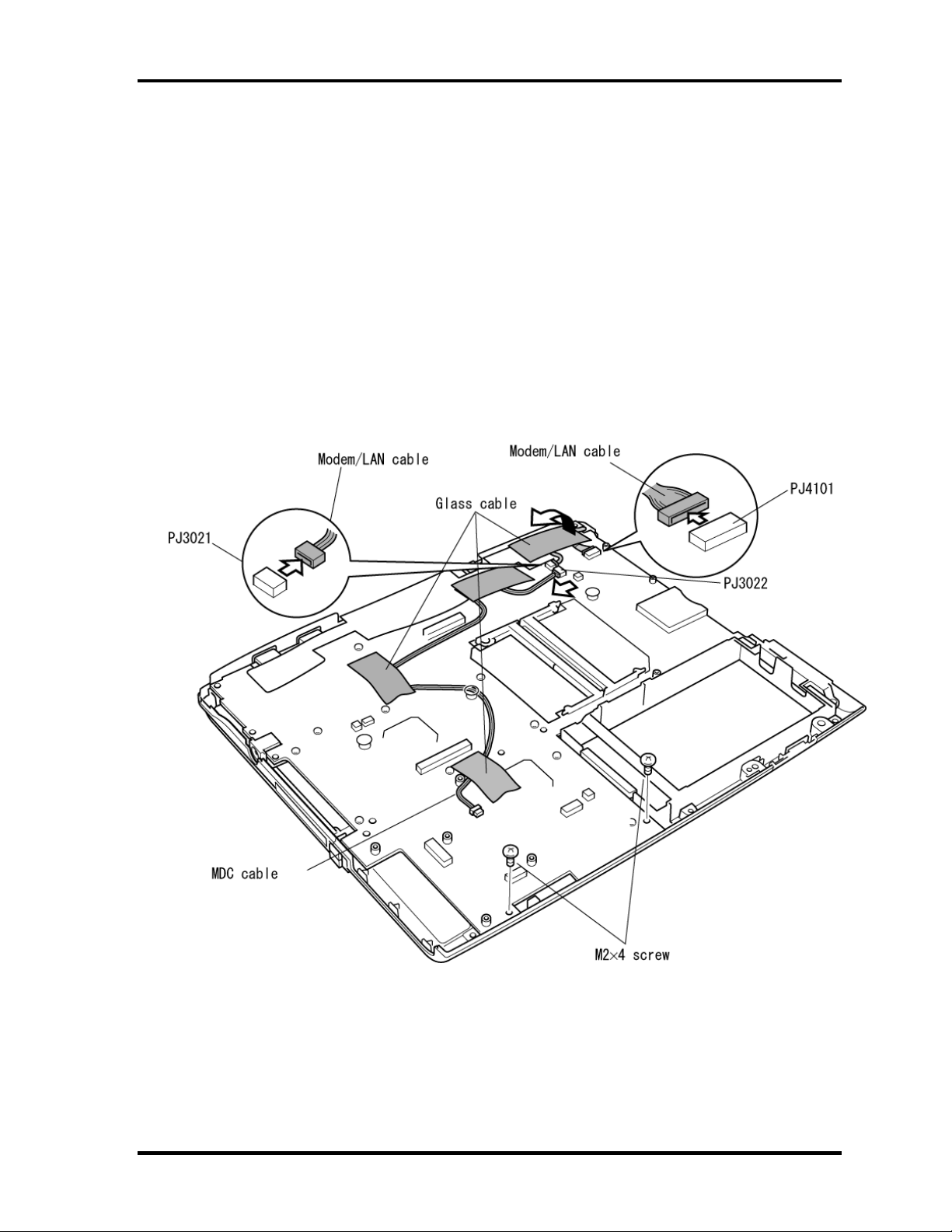
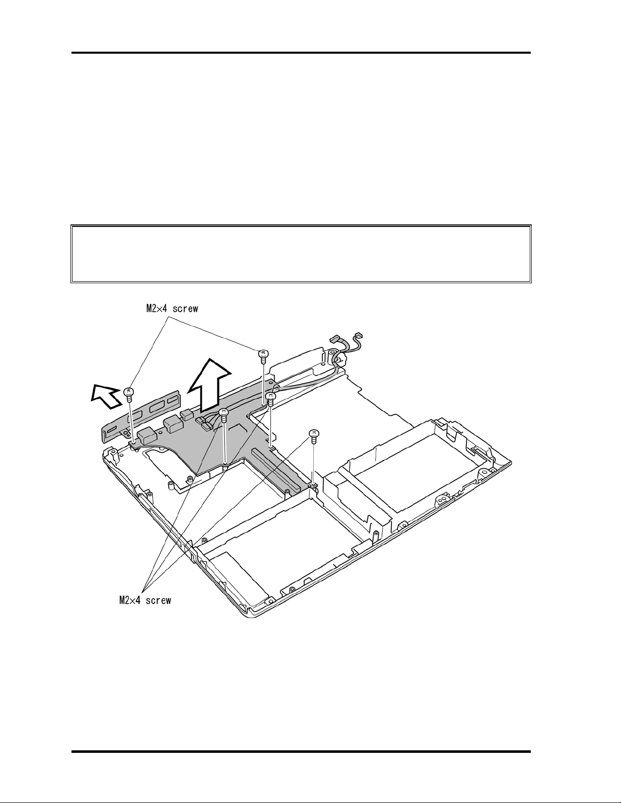
1. Remove two M2×4 screws securing the system board.
2. Remove the glass tapes securing the MDC cable and Modem/LAN cable.
3. Disconnect the MDC cable from the connector PJ3022 on the system board.
4. Disconnect the Modem/LAN cable from PJ3021 and PJ4101 on the system board.
Figure 4-35 Removing the screws securing the system board
PORTEGE M100 Maintenance Manual (960-452) 4-55
Page 5
4 Replacement Procedures 4.15 System Board
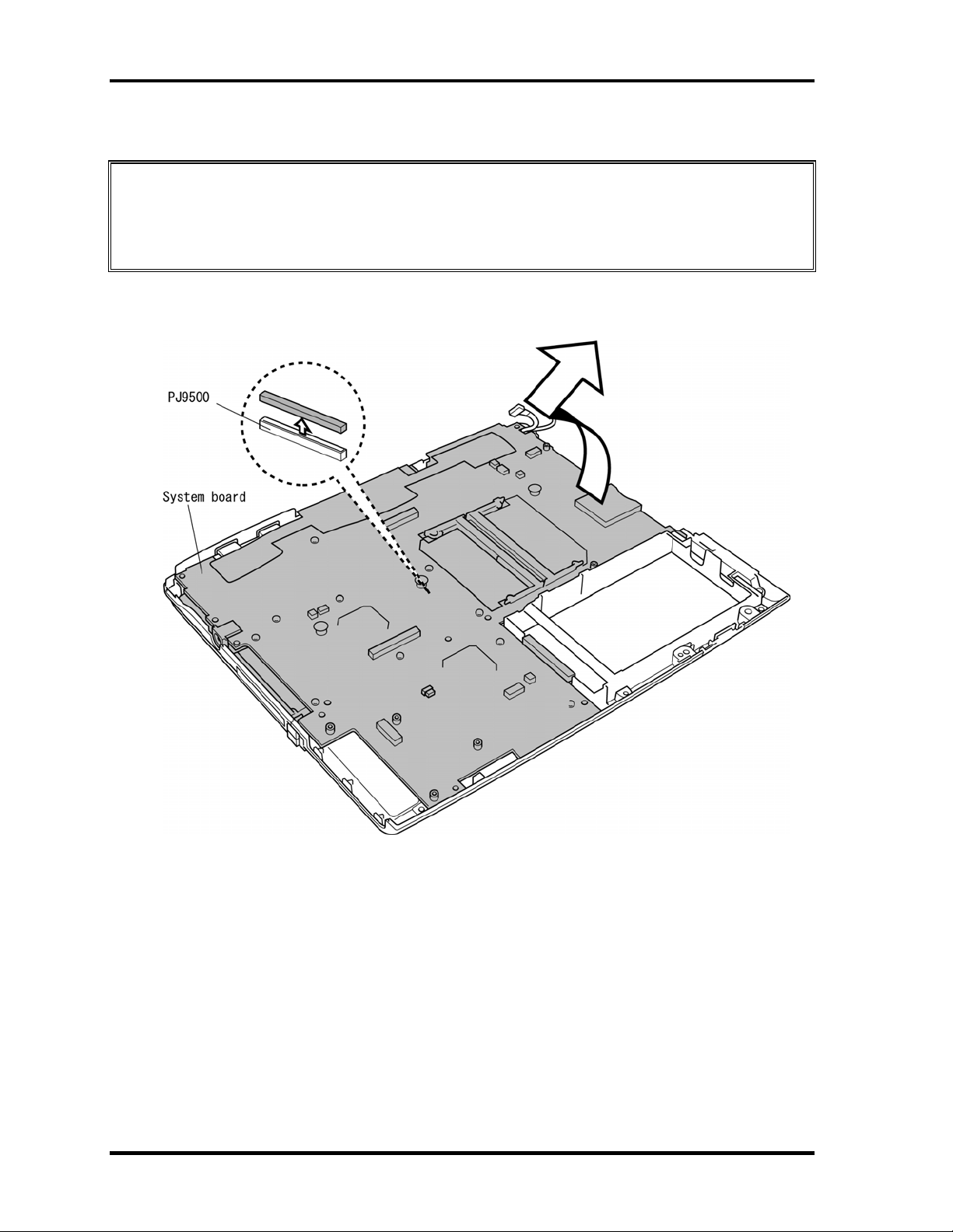
5. Carefully lift up the system board to disconnect it from PJ9500 on the I/O board.
CAUTION: The system board is connected to the IO board by stacking connectors. When
removing the system board, be sure to lift up the system board
perpendicularly and gently. Do not to give excessive stress to the
connectors. Otherwise the soldered portions of connectors may be damaged
Figure 4-36 Removing the system board
4-56 PORTEGE M100 Maintenance Manual (960-452)
Page 6
4.15 System Board 4 Replacement Procedures
Installing the System Board
To install the system board, follow the steps below and refer to figures 4-35 to 4-37.
1. Seat the system board.
2. Connect the system board to PJ9500 on the I/O board.
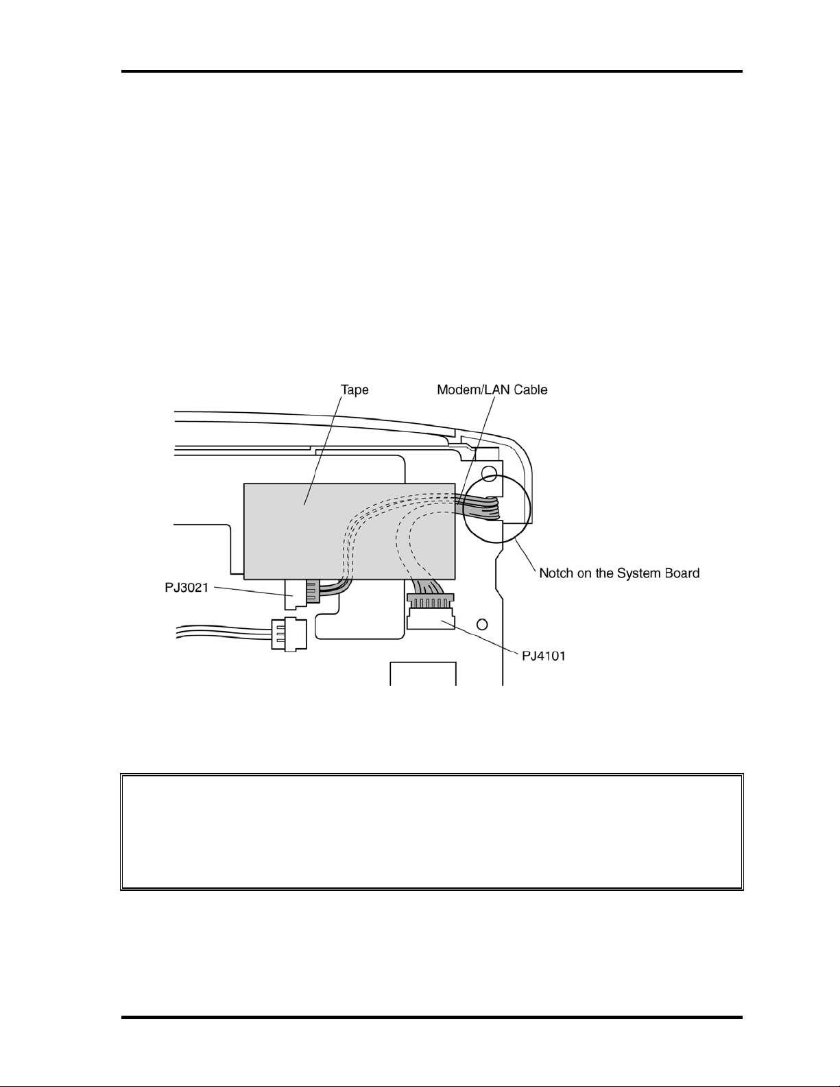
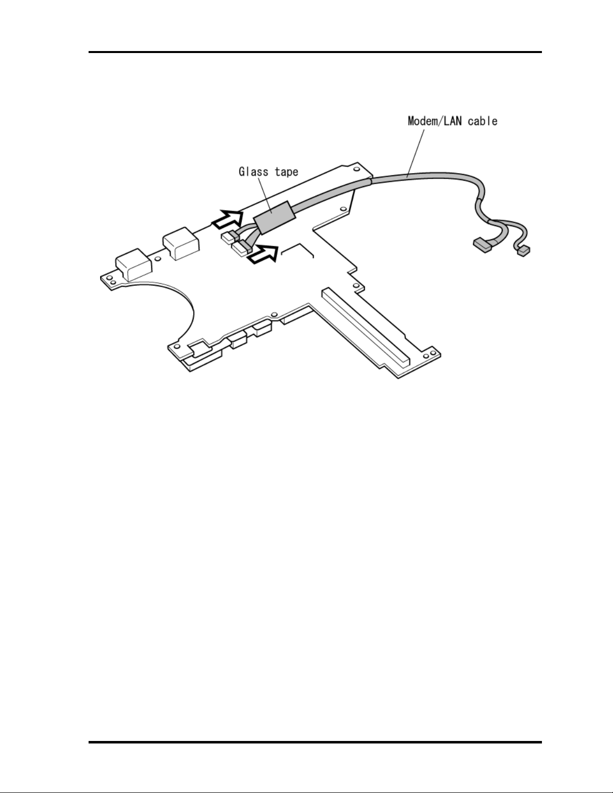
3. Route the Modem/LAN cable through the notch of the system board.
4. Connect the MDC cable to the connector PJ 3022 and Modem/LAN cable to the
connector PJ3021/PJ4101 on the system board.
5. Secure the cables with glass tapes.
Figure 4-37 Seating the cables
CAUTION: Make sure the cable lies inside the notch. Be careful not to damage or pinch
the cables when you seat the system board in the bottom case.
Secure the cable with a glass tape referring to Figure 4-37.
Be careful not to lay the cable on the lead of DIP of the RJ11/RJ45
connector.
PORTEGE M100 Maintenance Manual (960-452) 4-57
Page 7
4 Replacement Procedures 4.15 System Board
6. Secure the system board with two M2×4 screws.
CAUTION: Make sure you connect the boards securely. A loose connection could cause
damage to the boards. Also, if the connectors are not fully seated the boards
could be bent and damaged when you secure them with screws.
CAUTION: There are two MAC address barcode labels in the package containing the
new system board. Apply one label to the bottom of the computer and one to
the box the computer was shipped in. Before you apply the new labels,
remove the old ones from the computer and the box. The computer may have
MAC address barcode labels for both wired and wireless LANs. Be sure to
replace the correct label.
4-58 PORTEGE M100 Maintenance Manual (960-452)
Page 8
4.16 PC Card Slot 4 Replacement Procedures
4.16 PC Card Slot
Removing the PC card slot
To remove the PC card slot, follow the steps below and refer to figures 4-38 and 4-39.
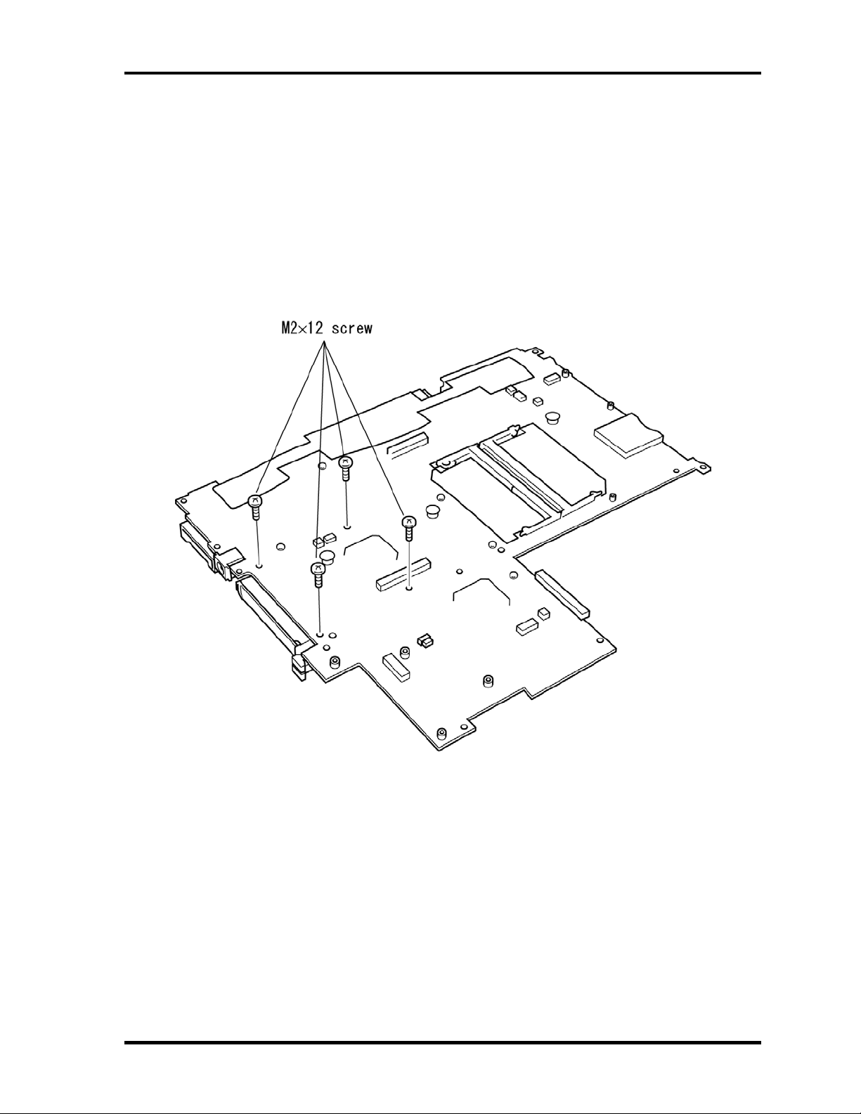
1. Lay the system board right side up.
2. Remove four M2×12 screws.
Figure 4-38 Removing four screws securing PC card slot
PORTEGE M100 Maintenance Manual (960-452) 4-59
Page 9
4 Replacement Procedures 4.16 PC Card Slot
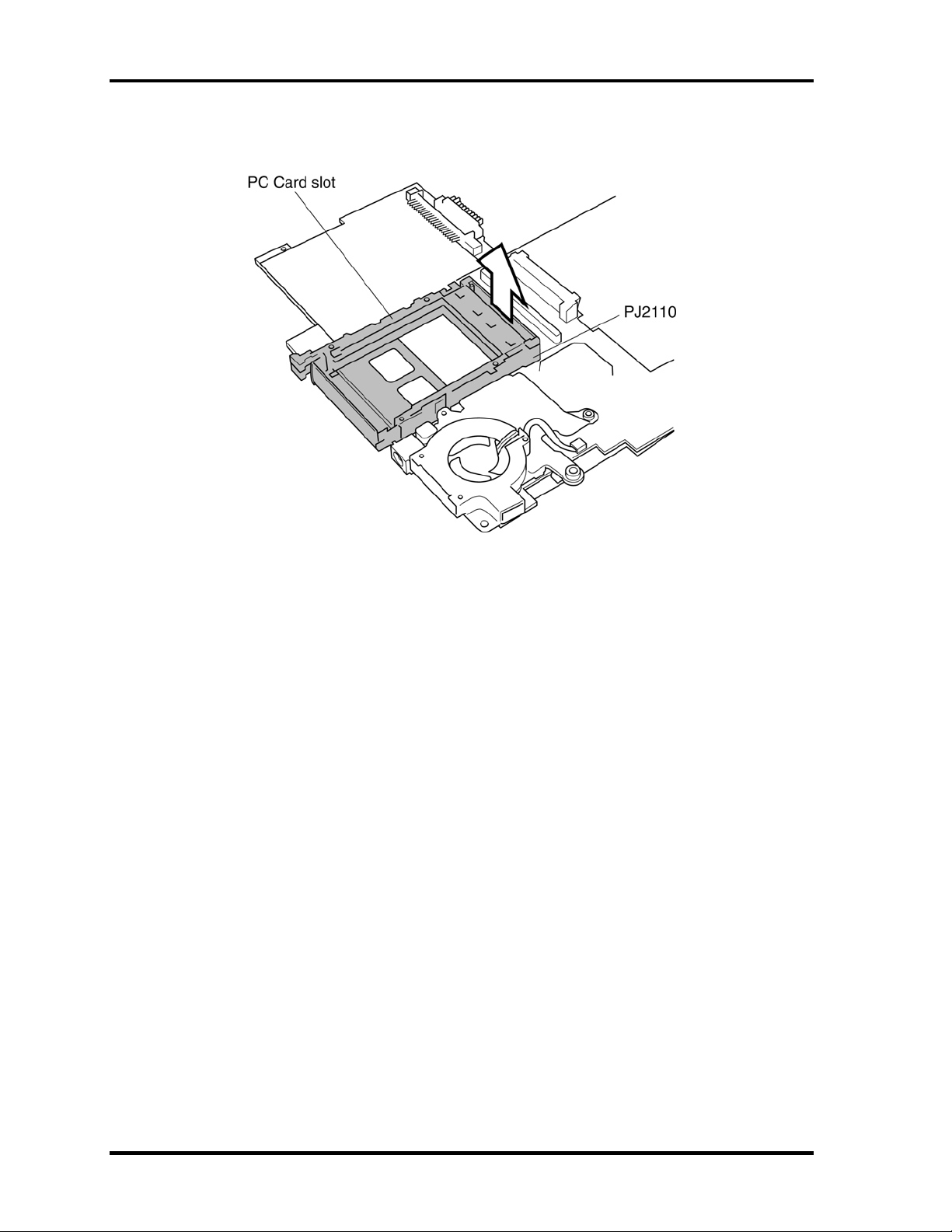
3. Lift up the PC card slot to disconnect from the connector PJ2110.
Figure 4-39 Removing the PC card slot
4-60 PORTEGE M100 Maintenance Manual (960-452)
Page 10
4.16 PC Card Slot 4 Replacement Procedures
Installing the PC card slot
To install the PC card slot, follow the steps below and refer to figures 4-38 and 4-39.
1. Fit the PC card slot into the connector PJ2110 on the system board.
CAUTION: If you do not seat the PC card slot completely, you might not be able to
connect the system board properly. Make sure the plastic part of the PC
card spot is flush with the connector.
2. Secure four M2×12 screws.
PORTEGE M100 Maintenance Manual (960-452) 4-61
Page 11
4 Replacement Procedures 4.17 I/O Board
4.17 I/O Board
Removing the I/O Board
To remove the I/O Board, follow the steps below and refer to figures 4-40 and 4-41.
1. Remove five M2×4 screws securing the I/O Board.
2. Lift out the I/O Board.
CAUTION: When removing the IO board, be sure to lift up it perpendicularly and gently.
Do not to give excessive stress to the stacking connectors. Otherwise the
soldered portions of connectors may be damaged.
Figure 4-40 Removing six screws securing the I/O Board
4-62 PORTEGE M100 Maintenance Manual (960-452)
Page 12
4.17 I/O Board 4 Replacement Procedures
3. If necessary, remove the Modem/LAN cable with peeling off the glass tape.
Figure 4-41 Removing the Modem/LAN cable
PORTEGE M100 Maintenance Manual (960-452) 4-63
Page 13
4 Replacement Procedures 4.17 I/O Board
Installing the I/O board
To install the I/O board, follow the steps below and refer to figures 4-40 and 4-41.
1. Connect the Modem/LAN cable to the I/O board and fix it with the glass tape.
2. Seat the I/O board.
3. Secure the I/O board with five M2×4 screws.
CAUTION: Make sure you connect the boards securely. A loose connection could cause
damage to the boards. Also, if the connectors are not fully seated the boards
could be bent and damaged when you secure them with screws.
4-64 PORTEGE M100 Maintenance Manual (960-452)
Page 14
4.18 Display Mask 4 Replacement Procedures
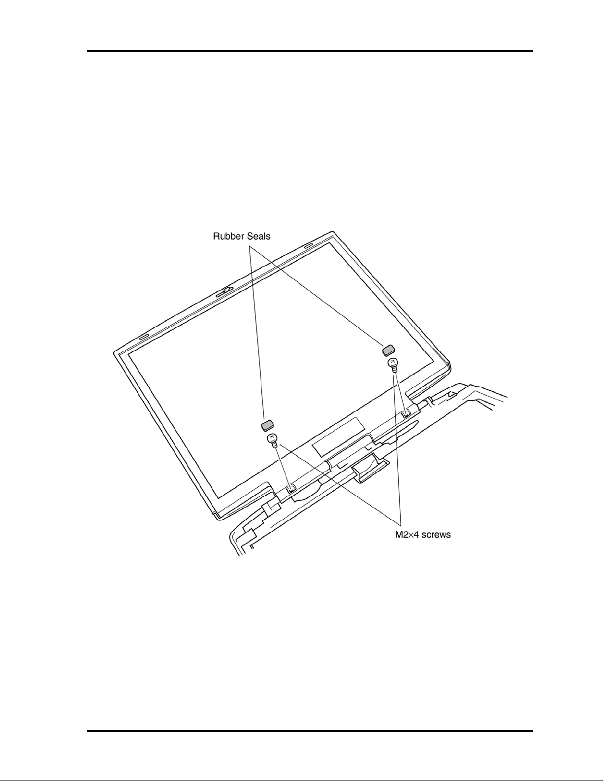
4.18 Display Mask
Removing the display mask
To remove the display mask, follow the steps below and refer to figures 4-42 and 4-43.
1. Remove the rubber seals with tweezers.
2. Remove two M2×4 screws securing display mask.
Figure 4-42 Removing the rubber seals and screws
PORTEGE M100 Maintenance Manual (960-452) 4-65
Page 15

4 Replacement Procedures 4.18 Display Mask
3. Release latches securing the display mask and remove the mask.
CAUTION: When releasing latches, do not give excessive force to the thin parts of
display mask.
Figure 4-43 Removing the display mask
4-66 PORTEGE M100 Maintenance Manual (960-452)
Page 16

4.18 Display Mask 4 Replacement Procedures
Installing the display mask
To install the system board, follow the steps below and refer to figures 4-42 and 4-43.
1. Seat the display mask and press to secure latches in the order of upper, right, left and
lower side.
2. Secure the display mask with two M2×4 screws.
3. Secure the rubber seals with tweezers.
PORTEGE M100 Maintenance Manual (960-452) 4-67
Page 17

4 Replacement Procedures 4.21 FL Inverter Board
4.19 FL Inverter Board
Removing the FL inverter board
To remove the FL inverter board, follow the steps below and refer to figure 4-44.
1. Remove one M2x4 flat-head screw securing the FL inverter board.
Figure 4-44 Removing two screws
2. Peel off insulators on both the sides of FL inverter board.
3. Disconnect the FL cable from CN1 on the FL inverter board.
4. Disconnect the HV cable from CN2 on the FL inverter board.
5. Remove the FL inverter board.
4-68 PORTEGE M100 Maintenance Manual (960-452)
Page 18

4.19 FL Inverter Board 4 Replacement Procedures
Installing the FL inverter board
To install the FL inverter board, follow the steps below and refer to figure 4-44.
1. Connect the HV cable to CN2 on the FL inverter board.
2. Connect the FL cable to CN1 on the FL inverter board.
3. Seat the FL inverter board and secure it with one M2x4 flat-head screw.
4. Stick insulators to both sides of FL inverter board.
PORTEGE M100 Maintenance Manual (960-452) 4-69
Page 19

4 Replacement Procedures 4.20 LCD Module
4.20 LCD Module
Removing the LCD module
To remove the LCD module, follow the steps below and refer to figures 4-45 and 4-46.
CAUTION: You do not need to remove the LCD module’s metal fittings unless you are
going to change the LCD module or FL.
1. Remove four M2×4 screws securing the LCD module.
Figure 4-45 Removing four screws
4-70 PORTEGE M100 Maintenance Manual (960-452)
Page 20

4.20 LCD Module 4 Replacement Procedures
2. Lift up the left side of the LCD module as indicated by the arrow in the figure below.
3. Peel off the glass tape fixing the LCD connector.
4. Disconnect the LCD cable from the LCD connector and remove the LCD module.
Figure 4-46 Removing the LCD module
PORTEGE M100 Maintenance Manual (960-452) 4-71
Page 21

4 Replacement Procedures 4.20 LCD Module
Installing the LCD module
To install the LCD module, follow the steps below and refer to figures 4-45 and 4-46.
1. Connect the LCD cable to the LCD connector on the back of the LCD module.
2. Fix the connected part of the LCD cable with a glass tape.
3. Seat the LCD module in the display panel.
4. Secure the LCD module with four M2×4 screws.
4-72 PORTEGE M100 Maintenance Manual (960-452)
Page 22

4.21 LCD/LED Cable 4 Replacement Procedures
4.21 LCD/LED Cable
Removing the LCD/LED cable
To remove the LCD cable, follow the steps below and refer to figures 4-47 to 4-50.
1. Remove two M2.5×4 black screws securing the display hinge.
2. Remove the top cover.
Figure 4-47 Removing two screws and the top cover
PORTEGE M100 Maintenance Manual (960-452) 4-73
Page 23

4 Replacement Procedures 4.21 LCD/LED Cable
3. Remove one M2×3 silver flat-head screw securing a plastic brace.
Figure 4-48 Removing one screw and plastic brace
4-74 PORTEGE M100 Maintenance Manual (960-452)
Page 24

4.21 LCD/LED Cable 4 Replacement Procedures
4. Lift out the LED board from the hook.
5. Peel off the tape and remove the LED cable and the LCD cable together.
Figure 4-49 Removing the LED board and the tape securing LED cable
6. If necessary, remove the LED cable from the LED board.
Figure 4-50 Removing the LED cable from LED board
PORTEGE M100 Maintenance Manual (960-452) 4-75
Page 25

4 Replacement Procedures 4.21 LCD/LED Cable
Installing the LCD/LED cable
To install the LCD/LED cable, follow the steps below and refer to figures 4-47 to 4-50.
CAUTION: Do not bend or scrub the LCD/LED cable. A slight damage may cause break
down of it. Be careful not to damage it.
1. Route the LCD/LED cable through the display hinge and seat the plastic brace.
2. Seat the LED board in the display panel.
3. Seat the display hinge in the display panel.
4. Seat the plastic brace and secure it with one M2×3 silver flat-head screw.
CAUTION: When seating the plastic brace, make sure the LCD/LED cable, wireless
LAN antenna and bluetooth antenna are not pinched. Be careful not to
damage them.
5. Secure the display hinge with two M2.5×4 black screws.
4-76 PORTEGE M100 Maintenance Manual (960-452)
Page 26

4.22 Antenna Coaxial Cables 4 Replacement Procedures
4.22 Antenna Coaxial Cables
Removing the Antenna Coaxial Cables
To remove the antenna coaxial cables, follow the steps below and refer to figures 4-51 to 4-
54.
1. Remove two M2.5×4 black screws securing the display hinge.
2. Remove the top cover.
Figure 4-51 Removing two screws and the top cover
PORTEGE M100 Maintenance Manual (960-452) 4-77
Page 27

4 Replacement Procedures 4.22 Antenna Coaxial Cables
3. Remove one M2×3 silver flat-head screw securing one plastic brace.
Figure 4-52 Removing one screw and plastic brace
4. Remove two glass tapes securing the Bluetooth antenna coaxial cable.
4-78 PORTEGE M100 Maintenance Manual (960-452)
Page 28

4.22 Antenna Coaxial Cables 4 Replacement Procedures
5. Lift out the LED board from the hook.
6. If necessary, peel off the tape fixing the LED cable.
Figure 4-53 Removing the LED board and the tape securing LED cable
CAUTION: You do not need to remove the LCD/LED cable from the hinge unless you
are going to change the LCD/LED cable.
PORTEGE M100 Maintenance Manual (960-452) 4-79
Page 29

4 Replacement Procedures 4.22 Antenna Coaxial Cables
7. Peel off the tape and remove the antenna coaxial cables.
Figure 4-54 Removing the tape and the antenna
CAUTION: The tip of antenna is like film and is fit in the latch portion. Do not bent or
scrub it. A slight damage may cause break down of tip. Be careful not to
damage it.
4-80 PORTEGE M100 Maintenance Manual (960-452)
Page 30

4.22 Antenna Coaxial Cables 4 Replacement Procedures
Installing the Antenna Coaxial Cables
To install the antenna coaxial cables, follow the steps below and refer to figure 4-51 to 4-54.
CAUTION: The tip of antenna is like film and is fit in the latch portion. Do not bent or
scrub it. A slight damage may cause break down of tip. Be careful not to
damage it.
1. Route the antenna coaxial cables through the display hinge and seat the plastic
brace.
2. Route the LCD/LED cable and seat the LED board.
3. Seat the display hinge in the display panel.
4. Seat the plastic brace and secure it with one M2×3 silver flat-head screw.
CAUTION: When seating the plastic brace, make sure the LCD/LED cable, wireless
LAN antenna and bluetooth antenna are not pinched. Be careful not to
damage them.
5. Secure the display hinge with two M2.5×4 black screws.
PORTEGE M100 Maintenance Manual (960-452) 4-81
Page 31

4 Replacement Procedures 4.23 TFT FL
4.23 TFT FL (Model 12.1 Toshiba)
Removing the TFT FL (Model 12.1 Toshiba)
To remove the TFT FL (Model 12.1 Toshiba), follow the steps below and refer to Figures
4-55 to 4-58.
1. Carefully, turn the LCD module upside down on the flat surface of the table. To avoid
damaging the surface of the LCD module, lay it on a protective, dust-free sheet such
as a soft, clean cloth.
2. Remove the light-green tape securing the wire.
3. Remove the FPC protective sheet, the blue tape and the PCB sheet. Keep the PCB
sheet for reuse.
4. Remove four screws.
CAUTION: Do not damage the FPC.
Figure 4-55 Removing the tapes and sheet
4-82 PORTEGE M100 Maintenance Manual (960-452)
Page 32

4.23 TFT FL 4 Replacement Procedures
CAUTION: Use a point size 0 Phillips screwdriver to remove the screws. Do not damage
the PCB when you pull the FPC out of the hook on the frame.
5. Remove copper ground.
6. Remove the PCB from the backlight frame.
Figure 4-56 Removing the Copper-ground
PORTEGE M100 Maintenance Manual (960-452) 4-83
Page 33

4 Replacement Procedures 4.23 TFT FL
7. Turn the LCD module right side up.
8. Release three latches on the lamp side of the frame.
9. Release three latches on the opposite side of the frame.
CAUTION: Do not damage the FPC with the bend parts on the top side of the frame
when you remove the frame.
Figure 4-57 Removing the frame
4-84 PORTEGE M100 Maintenance Manual (960-452)
Page 34

4.23 TFT FL 4 Replacement Procedures
10. Separate the PCB-ASSY cell from the backlight unit in the illustrated below.
CAUTION: Do not damage the FPC. The TAB and the panel are connected with the
PCB.
Figure 4-58 Separating the panel
PORTEGE M100 Maintenance Manual (960-452) 4-85
Page 35

4 Replacement Procedures 4.23 TFT FL
Installing the TFT FL (Model 12.1 Toshiba)
To install the TFT FL (Model 12.1 Toshiba), follow the steps below and refer to Figures 4-59
to 4-70.
1. Lay a new backlight unit face up.
2. Remove the liner from the double-faced tape.
3. Make sure there is no dust, foreign matter or damage on the backlight or back side of
the cell, then install the PCB-ASSY cell to the backlight unit.
Figure 4-59 Laying a new backlight unit
4-86 PORTEGE M100 Maintenance Manual (960-452)
Page 36

4.23 TFT FL 4 Replacement Procedures
4. Lay the LCD panel with PCB-ASSY on top of the backlight unit.
a. Fit the top edge first.
Figure 4-60 Laying the LCD panel with PCB-ASSY (1/2)
PORTEGE M100 Maintenance Manual (960-452) 4-87
Page 37

4 Replacement Procedures 4.23 TFT FL
b. Lay the LCD panel in place.
Figure 4-61 Laying the LCD panel with PCB-ASSY (2/2)
4-88 PORTEGE M100 Maintenance Manual (960-452)
Page 38

4.23 TFT FL 4 Replacement Procedures
5. Secure the latches.
Figure 4-62 Securing the latches
PORTEGE M100 Maintenance Manual (960-452) 4-89
Page 39

4 Replacement Procedures 4.23 TFT FL
6. Move the PCB behind the LCD module.
Figure 4-63 Moving the PCB
4-90 PORTEGE M100 Maintenance Manual (960-452)
Page 40

4.23 TFT FL 4 Replacement Procedures
7. Turn the LCD module face down.
8. Insert copper ground between the backlight unit and frame.
Figure 4-64 Inserting Copper-ground
PORTEGE M100 Maintenance Manual (960-452) 4-91
Page 41

4 Replacement Procedures 4.23 TFT FL
9. Secure the screws (right side).
Figure 4-65 Securing the screws (right side)
10. Secure the screws (left side).
Figure 4-66 Securing the screws (left side)
4-92 PORTEGE M100 Maintenance Manual (960-452)
Page 42

4.23 TFT FL 4 Replacement Procedures
11. Apply new blue tape, aligning it with the hole for the FL cable. It must not protrude
beyond the module surface. Be sure to cover the edge of the frame.
Figure 4-67 Applying new blue tape
PORTEGE M100 Maintenance Manual (960-452) 4-93
Page 43

4 Replacement Procedures 4.23 TFT FL
12. Apply the transparent PCB tape. Align the tape with the edge of the sheet. It must not
protrude beyond the module surface. Cover the edge of the frame.
Figure 4-68 Applying the PCB tape
4-94 PORTEGE M100 Maintenance Manual (960-452)
Page 44

4.23 TFT FL 4 Replacement Procedures
13. Secure the wire with light-green tape as shown below.
Figure 4-69 Securing the wire with light-green tape
PORTEGE M100 Maintenance Manual (960-452) 4-95
Page 45

4 Replacement Procedures 4.23 TFT FL
14. Apply the transparent PCB cover sheet removed in step 3. Be sure it covers the PCB
properly.
Figure 4-70 Applying the transparent PCB cover
4-96 PORTEGE M100 Maintenance Manual (960-452)
 Loading...