

Page 1

T
T
O
O
S
HII
S
H
TOSHIBA NOTEBOOK
B
B
A
A
Maintenance Manual
Satellite L10
(960-Q01)
[CONFIDENTIAL]
Page 2

Contents:
1. Chapter 1 Hardware Overview ...........................1-1
2. Chapter 2 Troubleshooting Procedures...............2-1
3. Chapter 3 Test Program for Field........................ 3-1
4. Chapter 4 Replacement Procedures.....................4-1
1-ii [CONFIDENTIAL] Satellite L10 Maintenance Manual(960-Q01)
Page 3

Chapter 1
Hardware Overview
[CONFIDENTAIL]
Page 4

1 Hardware Overview
1-ii [CONFIDENTIAL] Satellite L10 Maintenance Manual(960-Q01)
Page 5

Chapter 1 Contents
1.1 Features......................................................................................................................1-1
1.2 System Block Diagram..............................................................................................1-5
1.3 2.5-inch Hard Disk Drive......................................................................................... 1-10
1.4 Optical Drive............................................................................................................ 1-12
1.4.1 DVD-ROM & CD-R/RW Drive ........................................................1-12
1.4.2 DVD Super Multi Drive.....................................................................1-15
1.5 Keyboard.................................................................................................................. 1-17
1.6 TFT Color Display...................................................................................................1-18
1.6.1 LCD Module ......................................................................................1-18
1.6.2 FL Inverter Board...............................................................................1-19
1.7 Power Supply........................................................................................................... 1-20
1.8 Batteries ...................................................................................................................1-22
1.8.1 Main Battery....................................................................................... 1-22
1.8.2 Battery Charging Control................................................................... 1-23
1.8.3 RTC battery........................................................................................ 1-24
1.9 AC Adapter .............................................................................................................. 1-25
Satellite L10 Maintenance Manual(960-Q01) [CONFIDENTIAL] 1-iii
Page 6

Figures
Figure 1-1 Front of the computer and the system units configuration ............................1-5
Figure 1-2 System block diagram....................................................................................1-6
Figure 1-3 2.5-inch HDD...............................................................................................1-10
Figure 1-4 DVD-ROM & CD-R/RW drive...................................................................1-12
Figure 1-5 DVD Super Muti drive................................................................................. 1-15
Figure 1-6 Keyboard...................................................................................................... 1-17
Figure 1-7 LCD module................................................................................................. 1-18
Tables
Table 1-1 2.5-inch HDD dimensions ........................................................................... 1-10
Table 1-2 2.5-inch HDD specifications........................................................................ 1-11
Table 1-3 DVD-ROM & CD-R/RW drive outline dimensions.................................... 1-12
Table 1-4 DVD-ROM & CD-R/RW drive specifications............................................ 1-13
Table 1-5 DVD Super Multi drive outline dimensions................................................ 1-15
Table 1-6 DVD Super Multi drive specifications ........................................................ 1-16
Table 1-7 LCD module specifications..........................................................................1-18
Table 1-8 FL inverter board specifications .................................................................. 1-19
Table 1-9 Power supply output rating.......................................................................... 1-21
Table 1-10 Battery specifications...................................................................................1-22
Table 1-11 Time required for charges of main battery .................................................. 1-23
Table 1-12 Data preservation time................................................................................. 1-23
Table 1-13 Time required for charges of RTC battery................................................... 1-24
Table 1-14 AC adapter specifications............................................................................1-25
1-iv [CONFIDENTIAL] Satellite L10 Maintenance Manual(960-Q01)
Page 7

Chapter 1 Hardware Overview
1 Features
1.1 Features
The Satellite L10 series are 2 spindle PCs running a Intel ® Celeron®-M processor
and Intel . Intel ® Mobile Pentium ®-M
The features are listed below.
Microprocessor
Microprocessor that is used will be different of the model.
If North Bridge is 852GM , it supports Celeron-M as follows
®
Intel
360 (1.40GHz)
370 (1.50GHz)
Celeron ®-M 350 (1.30GHz)
L1 cache : 64KB (32KB + 32KB)
L2 cache : 1MB
If North Bridge is 855GME, it supports Pentium-M as follows
®
Intel
Mobile Pentium ®-M
Pentium-M 1.60GHz (Processor Number ; 725)
1.70GHz (Processor Number ; 735)
1.80GHz (Processor Number ; 745)
2.00GHz (Processor Number ; 755)
2.10GHz (Processor Number ; 765)
L1 cache : 64KB (32KB + 32KB)
L2 cache : 2MB
Memory
If North Bridge is 852GM then
Two DDR266 SO-DIMM slots. Memory modules can be installed to provide a
maximum of 1GB. Memory modules are available in 256MB and 512MB sizes.
If North Bridge is 855GME then
Satellite L10 Maintenance Manual(960-Q01) [CONFIDENTIAL] 1-1
Page 8

Chapter 1 Hardware Overview
Two DDR333 SO-DIMM slots. Memory modules can be installed to provide a
maximum of 2GB. Memory modules are available in 256MB 512MB and 1GB sizes.
VRAM
Shared with System RAM.
HDD
Double (or single) 40GB, 60GB and 80GB internal drives. 2.5 inch x 9.5mm height.
USB FDD (Option)
USB FDD supports 720KB and 1.44MB.
1-2 [CONFIDENTIAL] Satellite L10 Maintenance Manual (960-Q01)
Page 9

Chapter 1 Hardware Overview
Display
LCD
Built-in 15.0-inch, XGA (1024 x 768 dots), 262,144 colors, amorphous silicon
TFT color display.
CRT
Supported via a RGB connector.
TV-out
S-VIDEO OUT port supported.
Keyboard
An-easy-to-use 84(US)/85(Euro)-key keyboard provides a numeric keypad overlay
for fast numeric data entry . The keyboard also includes two keys that have special
functions in Microsoft® Windows® XP. It supports software that uses a 101- or 102key enhanced keyboard.
PC card slot
The PC card slot (PCMCIA) accommodates one 5mm Type II card. The slot support
16-bit PC cards and Card Bus PC cards. CardBus supports 32-bit PC cards.
Satellite L10 Maintenance Manual(960-Q01) [CONFIDENTIAL] 1-3
Page 10

Chapter 1 Hardware Overview
Optical devices
A DVD-ROM & CD-R/RW drive or DVD Super Multi drive is equipped.
Battery
The RTC battery is equipped inside the computer.
The main battery is a detachable lithium ion battery (4,300mAh:Li-Ion, 8cell).
USB (Universal Serial Bus)
Three USB ports are provided. The ports comply with the USB2.0 standard, which
enables data transfer speeds 40 times faster than USB1.1 standard. USB1.1 is also
supported.
Sound system
An internal stereo speaker, external monaural microphone connector, stereo
headphone connector is also equipped.
Wireless LAN (Mini PCI slot) (BTO)
The wireless LAN is equipped on the mini PCI slot.
LAN/MODEM
Connectors for LAN and Modem are separately mounted.
1-4 [CONFIDENTIAL] Satellite L10 Maintenance Manual (960-Q01)
Page 11
Chapter 1 Hardware Overview
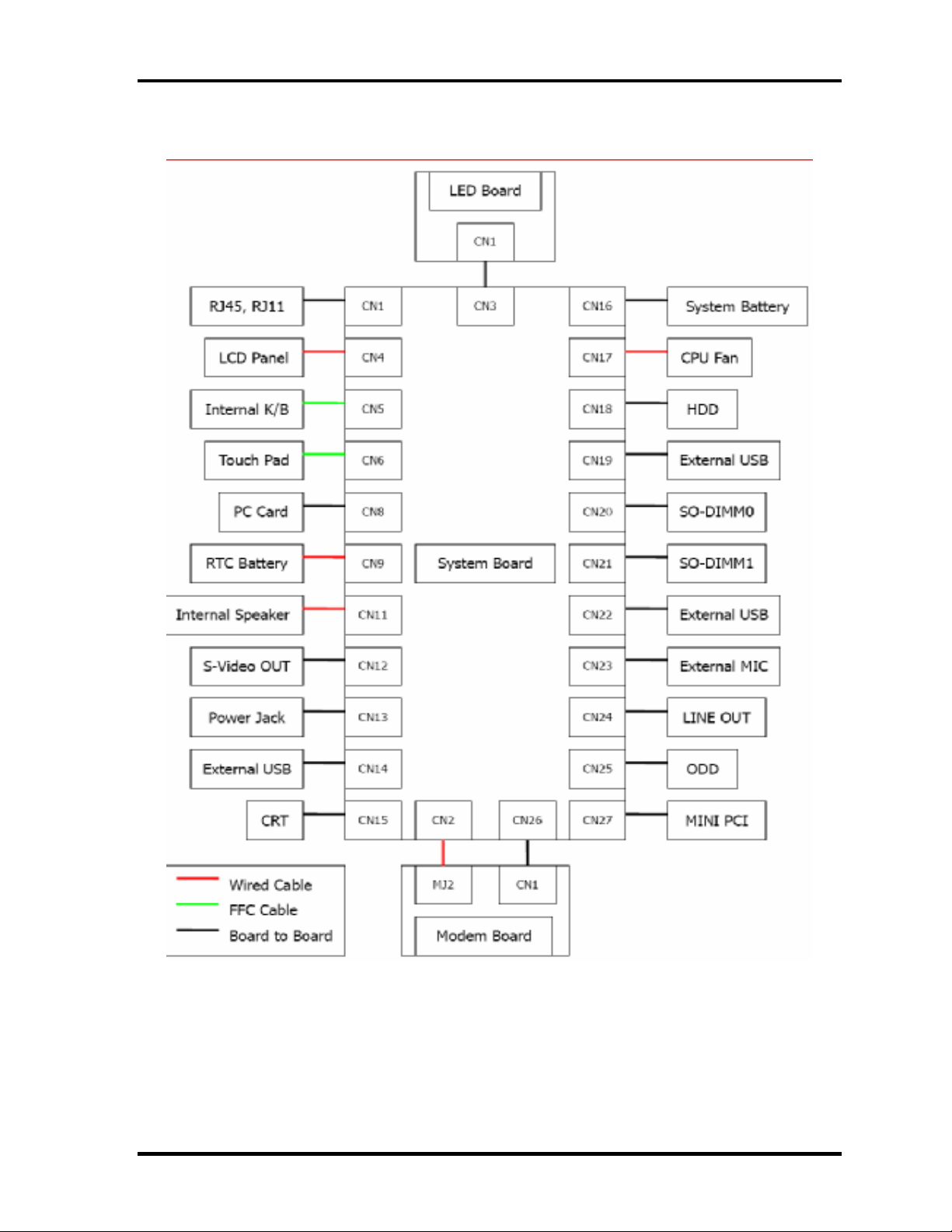
Figure 1-1 Front of the computer and the system units configuration
Satellite L10 Maintenance Manual(960-Q01) [CONFIDENTIAL] 1-5
Page 12
Chapter 1 Hardware Overview
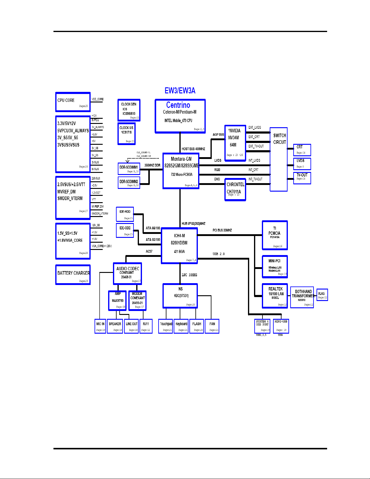
1.2 System Block Diagram
Figure 1-2 shows the system block diagram.
1-6 [CONFIDENTIAL] Satellite L10 Maintenance Manual (960-Q01)
Page 13

Chapter 1 Hardware Overview
Figure 1-2 System block diagram for 852GM/855GME Platform
Satellite L10 Maintenance Manual(960-Q01) [CONFIDENTIAL] 1-7
Page 14

Chapter 1 Hardware Overview
The PC contains the following components.
CPU
If the north bridge is 852GM , it supports Celeron-M CPU as follows
Intel ® Celeron ®-M 350 (1.30GHz)
360 (1.40GHz)
370 (1.50GHz)
L1 cache : 64KB (32KB + 32KB)
L2 cache : 1MB
FSB : 400MHz Core voltage : 1.26V
If the North Bridge is 855GME , It supports Pentium-M CPU as follows
Intel ® Mobile Pentium ®-M
Pentium-M 1.60GHz (Processor Number ; 725)
1.70GHz (Processor Number ; 735)
1.80GHz (Processor Number ; 745)
2.00GHz (Processor Number ; 755)
2.10GHz (Processor Number ; 765)
L1 cache : 64KB (32KB + 32KB)
L2 cache : 2MB
FSB : 400MHz Core voltage : 1.340~0.748V
Memory
If North Bridge is 852GM
Two memory slots capable of accepting DDR-SDRAM 256MB, or 512MB memory
modules for a maximum of 1GB.
• 200-pin SO-DIMM
• 2.5V operation
• PC2100 support
If North Bridge is 855GME
Two memory slots capable of accepting DDR-SDRAM 256MB, 512MB or 1GB
memory modules for a maximum of 2GB.
• 200-pin SO-DIMM
• 2.5V operation
• PC2100 support
1-8 [CONFIDENTIAL] Satellite L10 Maintenance Manual (960-Q01)
Page 15

Chapter 1 Hardware Overview
BIOS ROM (Flash memory)
• 4Mbit (512K×8-bit chip)
Chipset
This gate array has the following elements and functions.
• North Bridge (Intel 852GM (GMCH, B-step))
− Celeron-M processor System Bus support
− DRAM Controller : DDR266/DDR200 support
− Hub Link Interface
− 732-ball 37.5mmx37.5mm Mirco FC-BGA Package
• Or North Bridge (Intel 855GME (GMCH, B-step))
− Pentium-M processor System Bus support
− DRAM Controller : DDR333 support
− Hub Link Interface
− 732-ball 37.5mmx37.5mm Mirco FC-BGA Package
• South Bridge (Intel 82801DBM (ICH4-M))
− PCI slot
− IDE controller
− DMA controller
− USB host interface
− USB 2.0 host controller
− UHCI host controller
− Interrupt controller
− SM Bus interface
− ACPI Power management
− Firmware Hub interface
− Low Pin count (LPC) interface
− Real time clock
− AC’97 Rev. 2.3 interface
− Alert ON LAN (AOL)
− 421-pin 31mmx31mm BGA Package
PC card controller (PCI1410, Texas Instrument-made)
− PCI Interface (PCI Rev. 2.3)
− PC Card Controller
Satellite L10 Maintenance Manual(960-Q01) [CONFIDENTIAL] 1-9
Page 16

Chapter 1 Hardware Overview
VGA controller
• Intel VGA
− VRAM 16MB/32MB/64MB
− LVDS
Other main system chips
• Clock Generator (ICS-made ICS950810 x 1)
• EC/KBC (NS97551 x 1)
• AC97-CODEC (Conexant 20468-31 x1)
• Audio AMP (Maxim 9750x1)
• TV Encoder (Chrontel CH7011A)
•
Mini PCI
Wireless LAN card (BTO)
2.4GHz DSSS/OFDM LAN card is equipped. Conformity with IEEE 802.11b/g .
Transfer speed is maximum of 54Mbit/sec. Supports 128bit WEP.
LAN (Realtek RT8100CL x 1)
Controls LAN.
Supports 100Base-TX and 10Base-T.
MODEM (Conexant x 1)
Supported by on board Modem + DAA daughter card.
Data and FAX transmission is available.
Supports ITU-TV.90.
The transfer speed of data receiving is 56kbps, of data sending is 33.6kbps and of
FAX is 14.4kbps. Actual speed depends on the quality of the line used.
Connected to telephone line through RJ11 MODEM jack.
1-10 [CONFIDENTIAL] Satellite L10 Maintenance Manual (960-Q01)
Page 17
Chapter 1 Hardware Overview
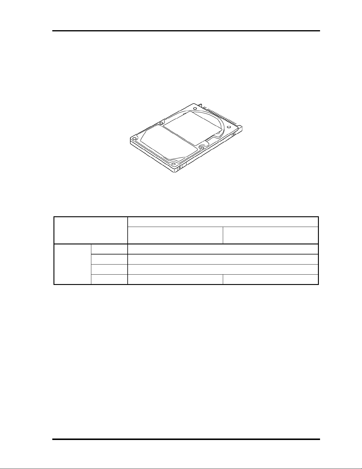
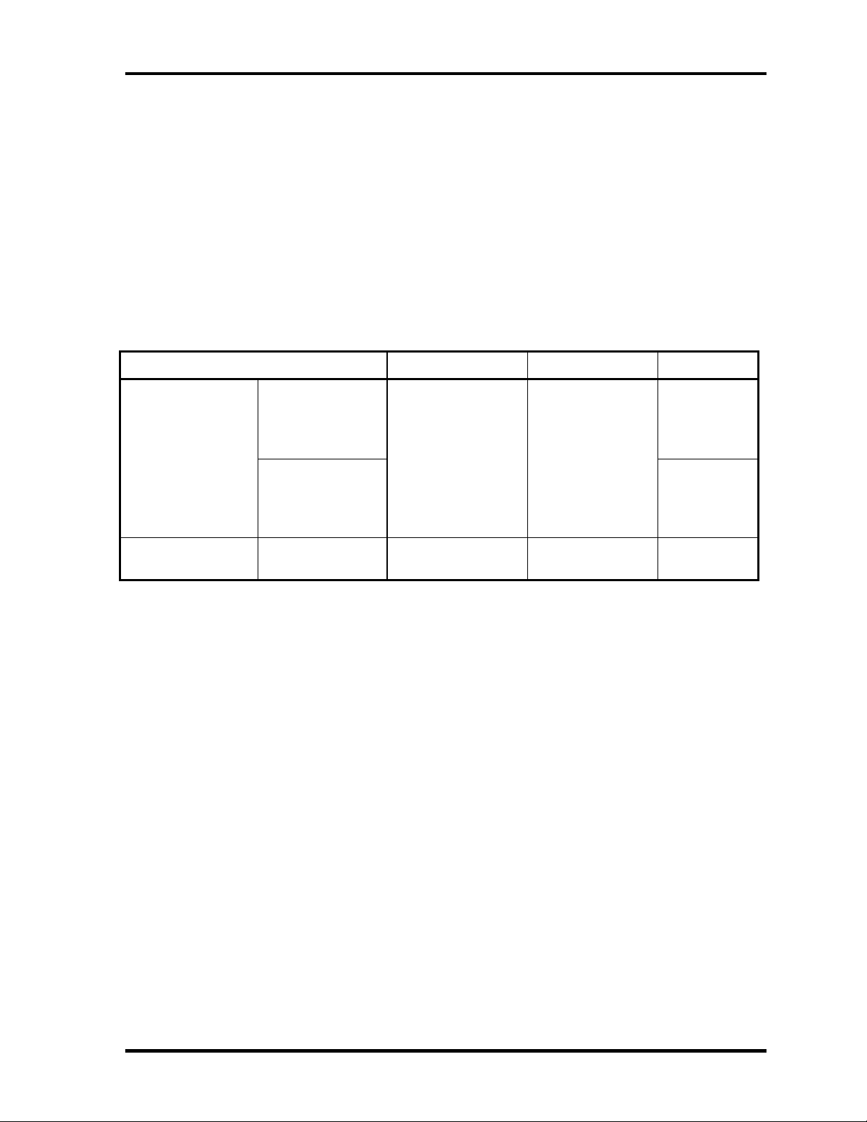
1.3 2.5-inch Hard Disk Drive
A compact, high-capacity HDD with a height of 9.5mm. Contains a 2.5-inch magnetic disk
and magnetic heads.
Figure 1-3 shows a view of the 2.5-inch HDD and Tables 1-1 and 1-2 list the specifications.
Figure 1-3 2.5-inch HDD
Outline
dimensions
Parameter
Width (mm)
Height (mm)
Depth (mm)
Weight (g)
Table 1-1 2.5-inch HDD dimensions
Standard value
TOSHIBA
MK4025GAS
69.85
9.5
100.0
94 (typ.) / 95 (max.) 94 (typ.) / 99 (max.)
TOSHIBA
MK6025GAS
Satellite L10 Maintenance Manual(960-Q01) [CONFIDENTIAL] 1-11
Page 18
Chapter 1 Hardware Overview
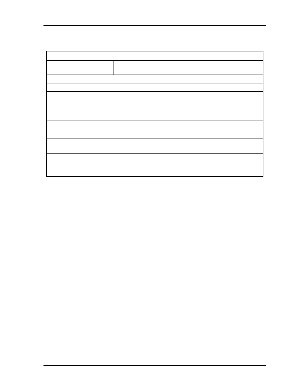
Table 1-2 2.5-inch HDD Specifications
Specification
Parameter
Storage size (formatted) 40GB 60GB
Speed (RPM) 4,200
Data transfer speed
(Mbits/s)
Interface transfer rate
(MB/s)
Storage density (Kbpi)
Track density (Ktpi)
Average random seek time
(read) (ms)
Average random seek time
(write) (ms)
Power-on-to-ready (sec) 4 (typ.) / 10 (max.)
TOSHIBA
MK4025GAS
175.0 ~ 341.7 201.6 ~ 307.5
100 (Ultra DMA Mode)
735 (max.) 658 (max.)
88.1 88.1
12
-
TOSHIBA
MK6025GAS
1-12 [CONFIDENTIAL] Satellite L10 Maintenance Manual (960-Q01)
Page 19
Chapter 1 Hardware Overview
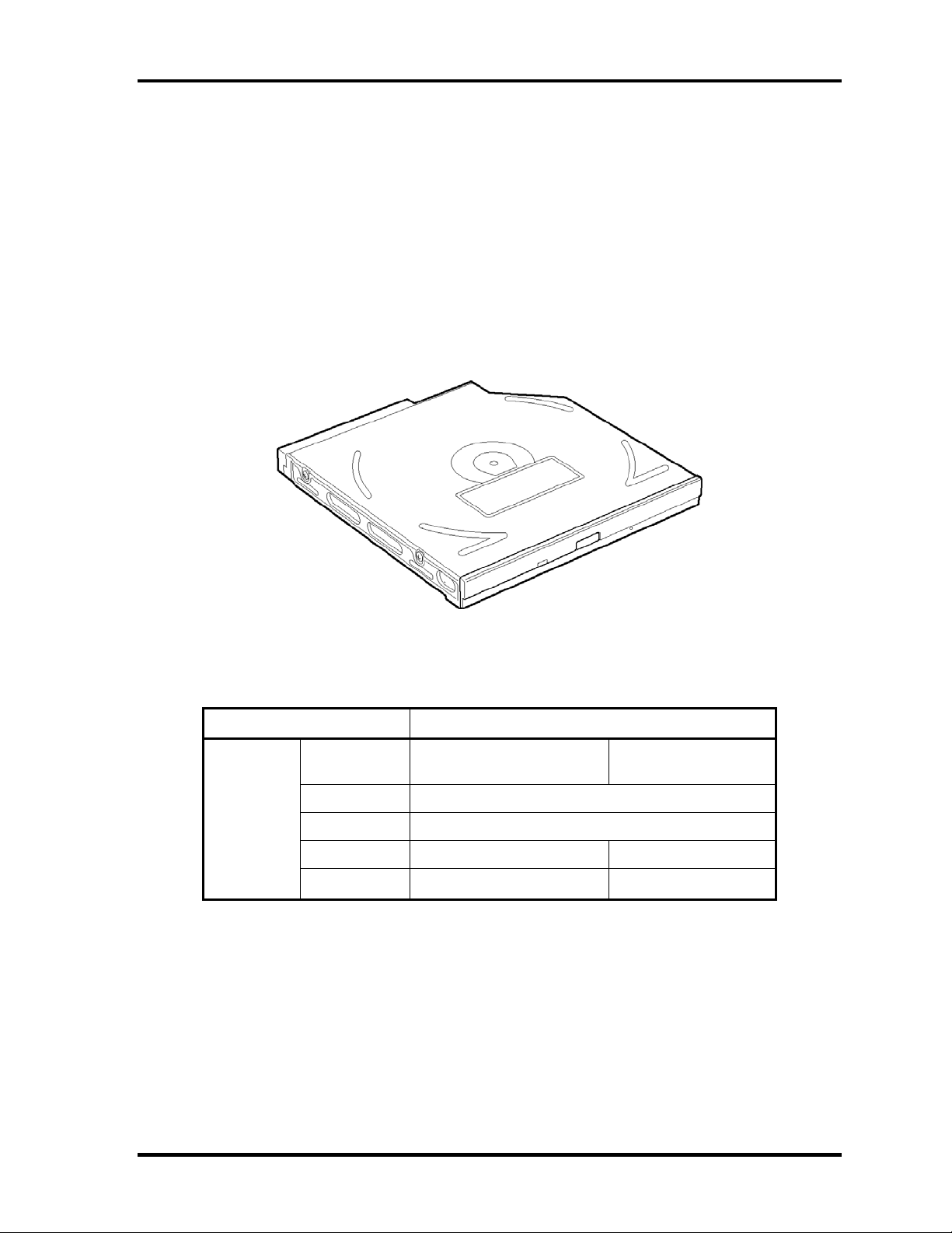
1.4 Optical Drive
1.4.1 DVD-ROM & CD-R/RW Drive
The DVD-ROM & CD-R/RW drive accommodates either 12 cm (4.72-inch) or 8 cm (3.15inch) CD/DVD-ROM and CD-R/RW. It is a high-performance drive that reads DVD at
maximum 8-speed and CD at maximum 24-speed.
The DVD-ROM & CD-R/RW drive is shown in Figure 1-4. The dimensions and
specifications of the DVD-ROM & CD-R/RW drive are described in Table 1-3, Table 1-4.
Figure 1-4 DVD-ROM & CD-R/RW drive
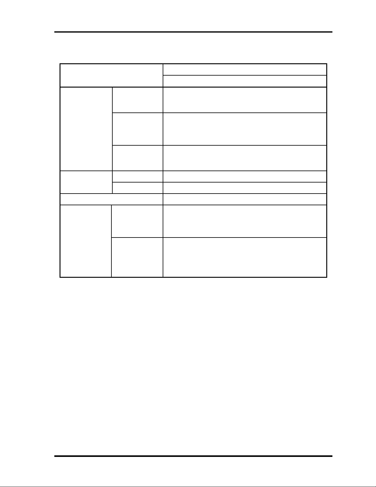
Table 1-3 DVD-ROM & CD-R/RW drive outline dimensions
Parameter Standard value
Outline
dimensions
Maker
Width (mm) 128
Height (mm) 12.7 (excluding projections)
Depth (mm) 129 127
Mass (g) 190±10 180
MATSUSHITA
(UJDA760TT-A)
TOSHIBA
(TS-L462A)
Satellite L10 Maintenance Manual(960-Q01) [CONFIDENTIAL] 1-13
Page 20
Chapter 1 Hardware Overview
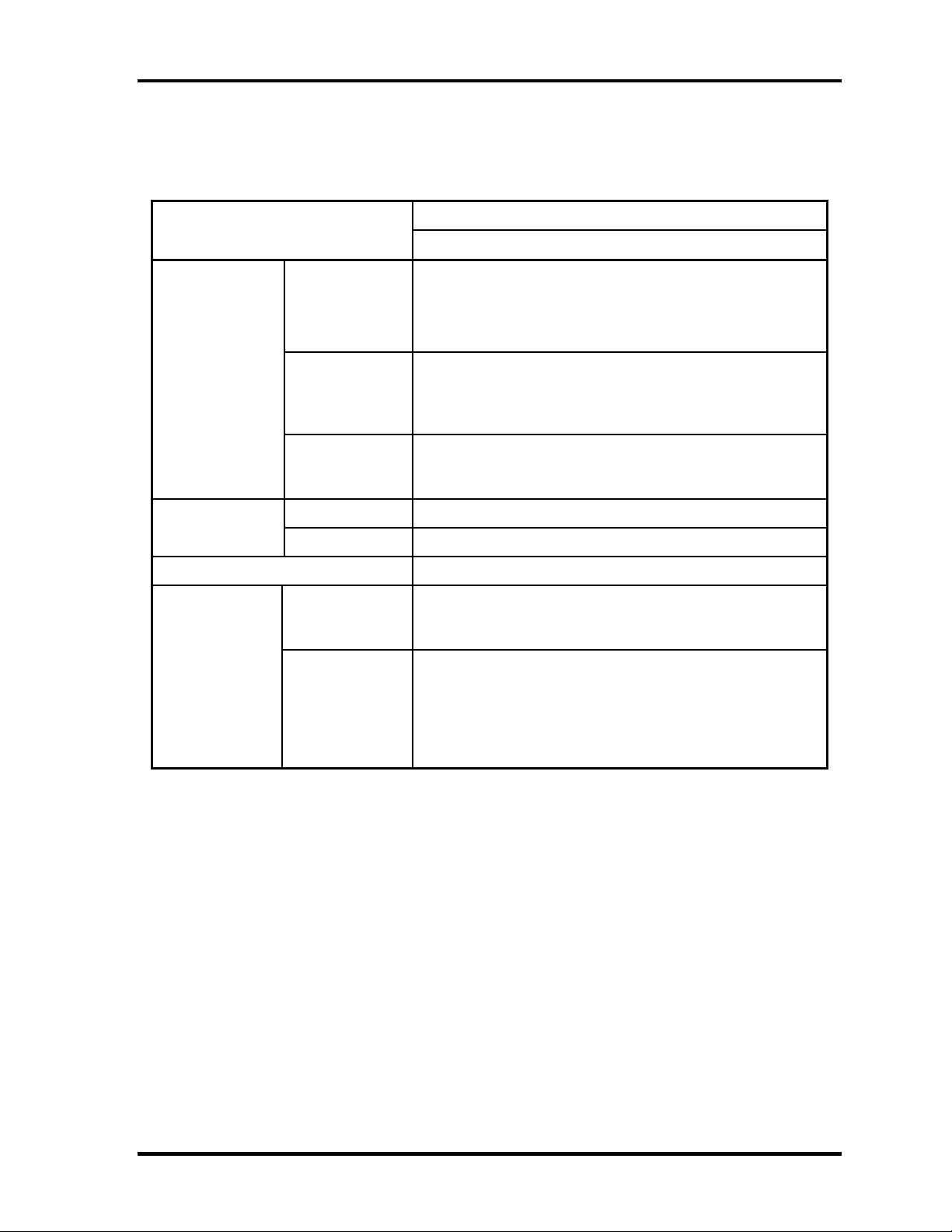
Table 1-4 DVD-ROM & CD-R/RW drive specifications (1/2)
Parameter
Data transfer
speed
Access time
(ms) (Random)
Buffer memory 2MB
Supported disk
format
Drive Specification
MATSUSHITA (UJDA760TT-A)
DVD-ROM MAX 8X CAV (MAX 10800 KB/s)
Read (KB/s)
Write
ATAPI interface
(MB/s)
CD-ROM 150ms
DVD-ROM 180ms
CD
DVD
DVD-R MAX 4X CAV (MAX 5400 KB/s)
CD-ROM MAX 24X CAV (MAX 3600 KB/s)
CD-R 4X,8X(CLV), 16X(PCAV), MAX24x(CAV)
CD-RW 4X (CLV)
High Speed CD-RW 4X,8X,10X (CLV)
Ultra Speed CD-RW 10X(CLV), Max24X(CAV)
PIO Mode4 (MAX 16.6 MB/s)
DMA Multiword Mode2 (MAX 16.6 MB/s)
Ultra DMA Mode2 (MAX 33.3 MB/s)
CD-DA,CD-ROM,CD-ROM XA
CD-R,CD-RW
Photo CD
CD-Extra(CD+),CD-text
DVD-ROM,DVD-Video
DVD-RAM(2.6GB/4.7GB)
DVD-R (DVD-R Multi Boarder supported)
DVD-RW(Ver.1.1)
DVD+R, DVD+RW (Support Multi Session)
1-14 [CONFIDENTIAL] Satellite L10 Maintenance Manual (960-Q01)
Page 21
Chapter 1 Hardware Overview
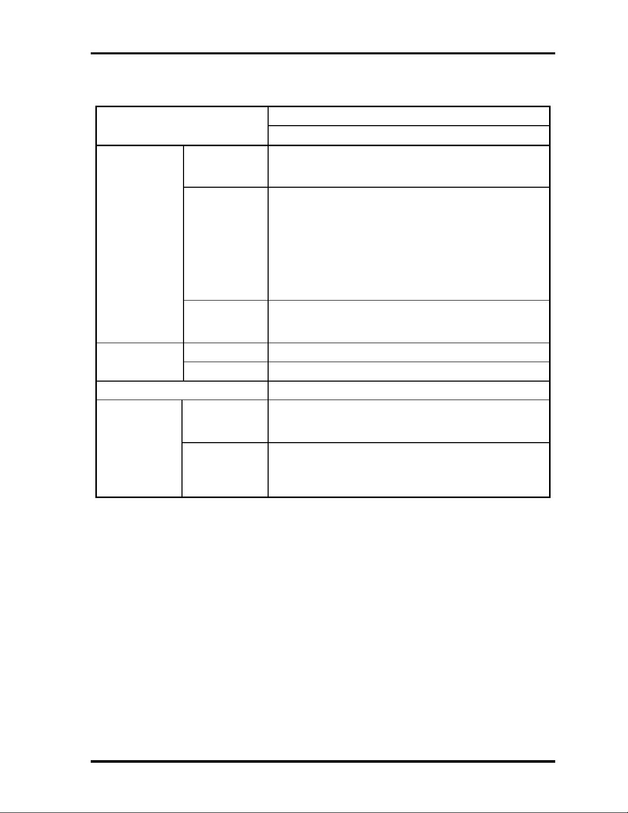
Table 1-4 DVD-ROM & CD-R/RW drive specifications (2/2)
Parameter
Data transfer
speed
Access time
(ms) (Random)
Buffer memory 2MB
Supported disk
format
Drive Specification
TOSHIBA (TS-L462A)
CD-ROM,CD-RW MAX 24X CAV (MAX 3,600KB/s)
Read (KB/s)
Write
ATAPI interface
(MB/s)
CD-ROM 130ms (typ.) / 160ms (max.)
DVD-ROM 130ms (typ.) / 160ms (max.)
CD
DVD
DVD-ROM MAX 8X CAV (MAX 10800KB/s)
DVD±R,DVD±RW MAX 6X (MAX 8100 KB/s)
DVD-RAM MAX 4X CAV (MAX 5400KB/s)
CD-R MAX 24X (P-CAV)
CD-RW 4X (CLV)
High Speed CD-RW 4X,10X (CLV)
Ultra Speed CD-RW 24X (P-CAV)
PIO Mode4 (MAX 16.7 MB/s)
DMA Multiword Mode2 (MAX 16.7 MB/s)
Ultra DMA Mode2 (MAX 33.3 MB/s)
CD-ROM Mode1&2S
CD-ROM XA Modo2 (Form1&2)
CD-DA, CD-I, CD-Extra/CD-Plus, Video-CD
DVD-ROM
DVD Video
DVD-R (General, Authoring)
DVD-RW (Single/Multi-boarder, Packet)
DVD-RAM
DVD+R/RW
Satellite L10 Maintenance Manual(960-Q01) [CONFIDENTIAL] 1-15
Page 22

Chapter 1 Hardware Overview
1.4.2 DVD Super Multi Drive
The DVD Super Multi drive accommodates either 12 cm (4.72-inch) or 8 cm (3.15-inch)
CD/DVD-ROM, CD-R/RW, DVD±R/±RW and DVD-RAM. It is a high-performance drive
that reads DVD-ROM at maximum 8-speed and CD at maximum 24-speed. Write speed of
DVD±R/±RW and DVD-RAM is different depending on the drive.
The DVD Super Multi drive is shown in Figure 1-5. The dimensions and specifications of the
DVD Super Multi drive are described in Table 1-5, Table 1-6.
Outline
dimensions
Figure 1-5 DVD Super Multi drive
Table 1-5 DVD Super Multi drive outline dimensions
Parameter Standard value
Maker
Width (mm) 128
Height (mm) 12.7
Depth (mm) 129.0
Mass (g) 210±10
MATSUSHITA
(UJ-830BTQ-A)
1-16 [CONFIDENTIAL] Satellite L10 Maintenance Manual (960-Q01)
Page 23
Chapter 1 Hardware Overview
Table 1-6 DVD Super Multi drive specifications (1/1)
Parameter
Data transfer
speed
Access time
(ms)
Buffer memory 2MB
Supported disk
format
Drive Specification
MATSUSHITA (UJ-830BTQ-A)
Read(KB/s)
Write
ATAPI interface
(MB/s)
CD-ROM 150 (Random)
DVD-ROM 180 (Random)
CD
DVD
DMA Multiword Mode2 (MAX 16.6 MB/s)
DVD-ROM MAX 8X CAV
CD-ROM MAX 24X CAV
CD-R MAX 24X (Zone CLV)
CD-RW 4X (CLV)
High Speed CD-RW 10X (CLV)
Ultra Speed CD-RW 10X (CLV)
DVD-R MAX 8X (Zone CLV)
DVD-RW MAX 4X (Zone CLV)
DVD+R MAX 8X (Zone CLV)
DVD+RW MAX 4X (Zone CLV)
DVD-RAM 3X (ZCLV) (4.7GB)
PIO Mode4 (MAX 16.6 MB/s)
Ultra DMA Mode2 (MAX 33.3 MB/s)
CD-DA, CD-ROM, Video CD
CD-ROM XA, Photo CD
CD-Extra(CD+),CD-text
DVD-ROM
DVD-R, DVD-RW (Ver1.1)
DVD+R/+RW, DVD Video,
DVD-RAM (2.6GB(read only)/4.7GB)
Satellite L10 Maintenance Manual(960-Q01) [CONFIDENTIAL] 1-17
Page 24
Chapter 1 Hardware Overview
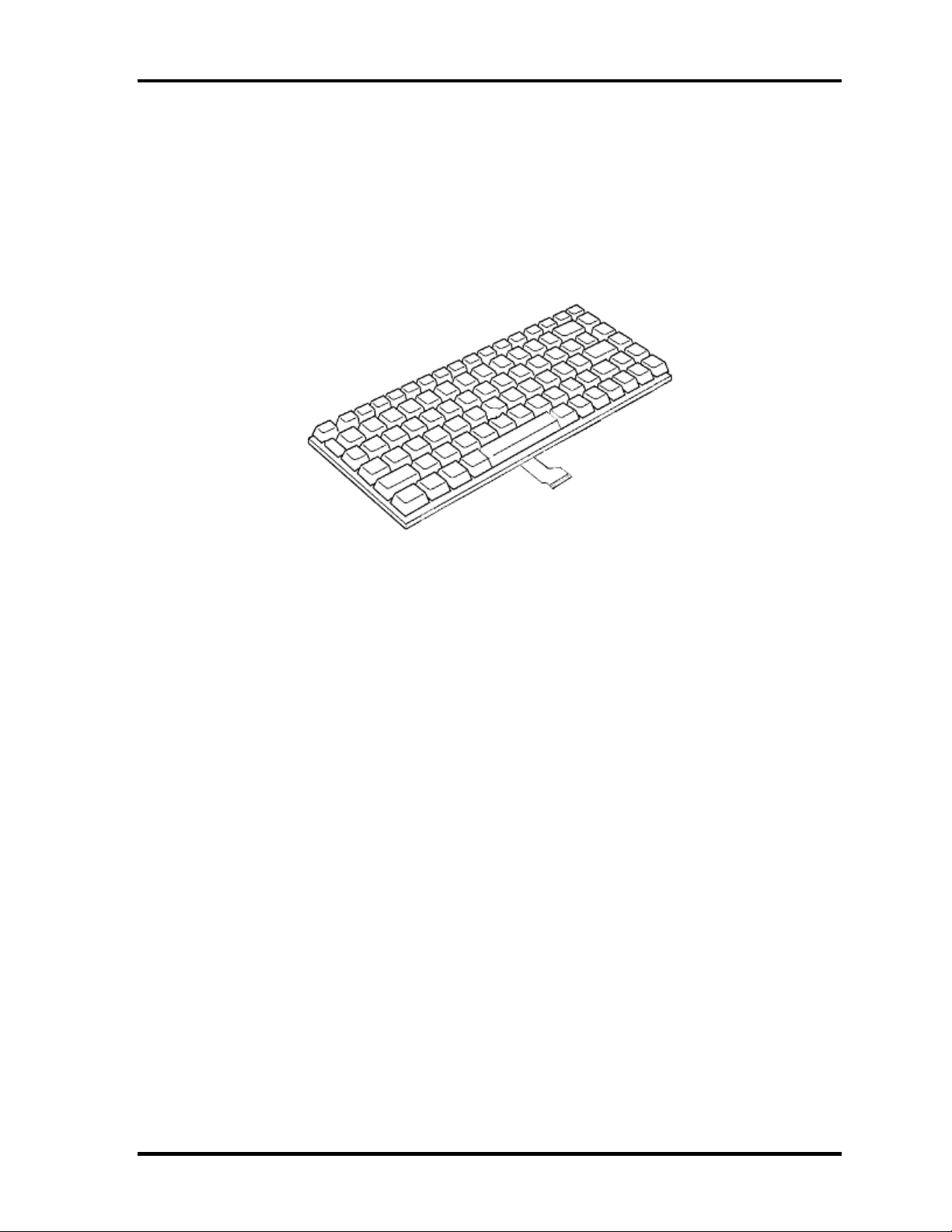
1.5 Keyboard
A keyboard which consists of 84(US)/85(Euro) keys is mounted on the system unit. The
keyboard is connected to membrane connector on the system board and controlled by the
keyboard controller.
Figure 1-6 is a view of the keyboard.
Figure 1-6 Keyboard
See Appendix E for details of the keyboard layout.
1-18 [CONFIDENTIAL] Satellite L10 Maintenance Manual (960-Q01)
Page 25
Chapter 1 Hardware Overview
1.6 TFT Color Display
The TFT color display is 15.0 inch and consists of LCD module and FL inverter board.
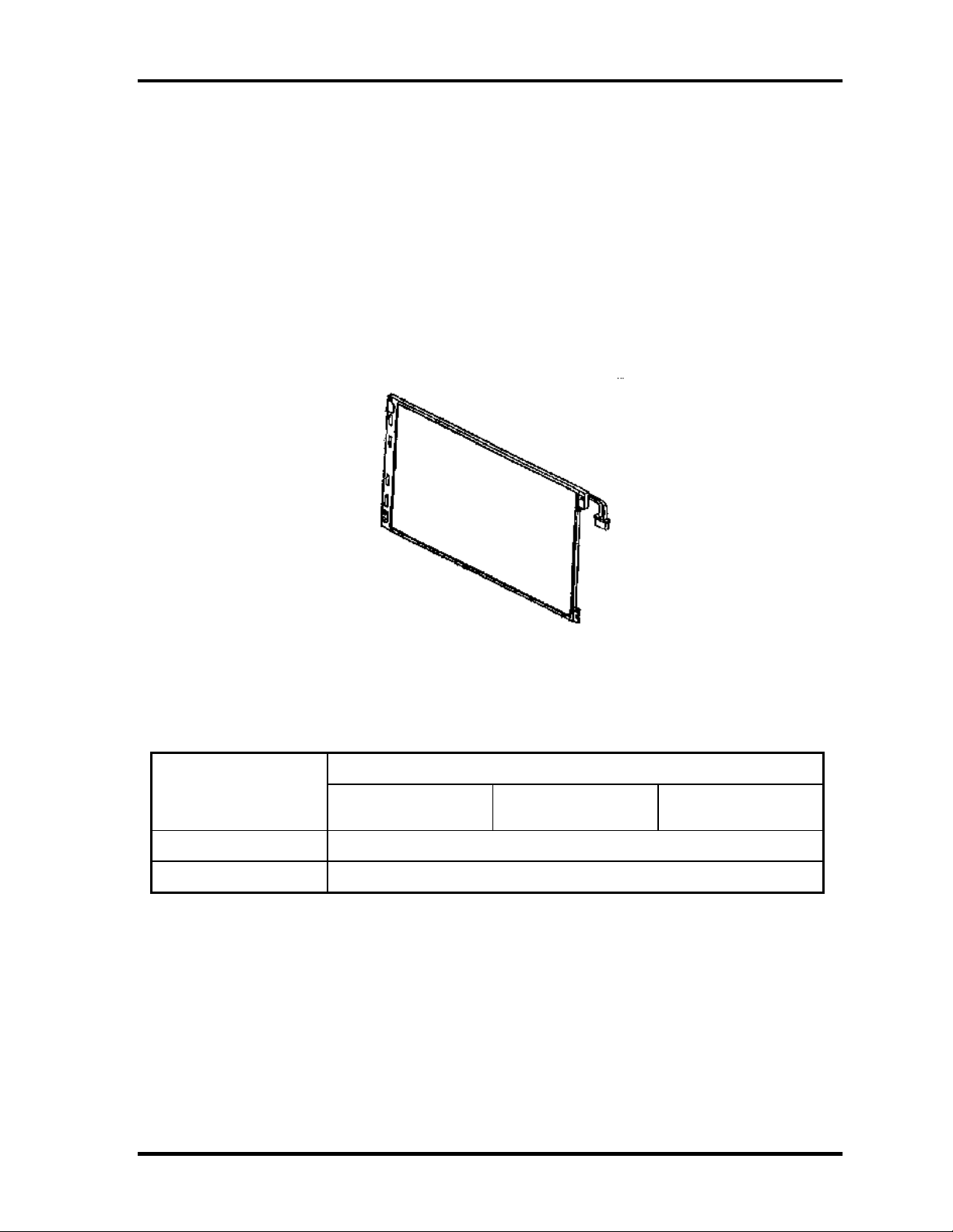
1.6.1 LCD Module
The LCD module used for the TFT color display uses a backlight as the light source and can
display a maximum of 262,144 colors with 1,024 x 768 resolution.
Figure 1-8 shows a view of the LCD module and Table 1-9 lists the specifications.
Item
Number of Dots
Dot spacing (mm)
Figure 1-7 LCD module
Table 1-7 LCD module specifications
Specifications
LG-Philips
LP150X08
1,024(W) × 768(H)
0.297(H)× 0.297(V)
CPT
CLAA150XH01
AU
B150XG01V.2
Satellite L10 Maintenance Manual(960-Q01) [CONFIDENTIAL] 1-19
Page 26
Chapter 1 Hardware Overview
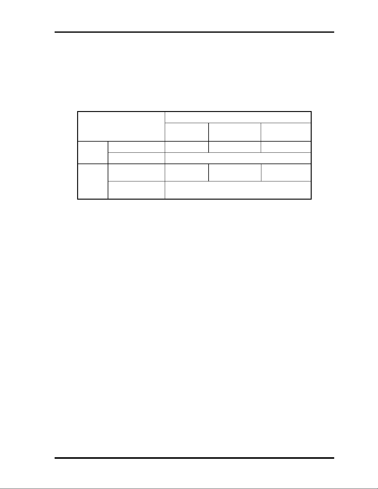
1.6.2 FL Inverter Board
The FL inverter board supplies a high frequency current to illuminate the LCD module FL.
Table 1-10 lists the FL inverter board specifications.
Table 1-8 FL inverter board specifications
Specifications
Item
Voltage (V) 8 ~ 20 8 ~ 20 7.5 ~ 21 Input
Power (W) 5
PI
FL9030
DELTA
DAC-08N009
SUMIDA
IV002
Output
Voltage (Vrms)
Current
(mArms)
(f=55KHz)
1500 1400 ~ 1800 1500 ~ 1900
6
1-20 [CONFIDENTIAL] Satellite L10 Maintenance Manual (960-Q01)
Page 27

Chapter 1 Hardware Overview
1.7 Power Supply
The power supply supplies 23 different voltages to the system board.
The power supply microcontroller has the following functions.
1. Judges if the DC power supply (AC adapter) is connected to the computer.
2. Detects DC output and circuit malfunctions.
3. Controls the battery icon, and DC IN icon.
4. Turns the battery charging system on and off and detects a fully charged battery.
5. Turns the power supply on and off.
6. Provides more accurate detection of a low battery.
7. Calculates the remaining battery capacity.
8. Controls the transmission of the status signal of the main battery.
Table 1-11 lists the power supply output specifications.
Satellite L10 Maintenance Manual(960-Q01) [CONFIDENTIAL] 1-21
Page 28
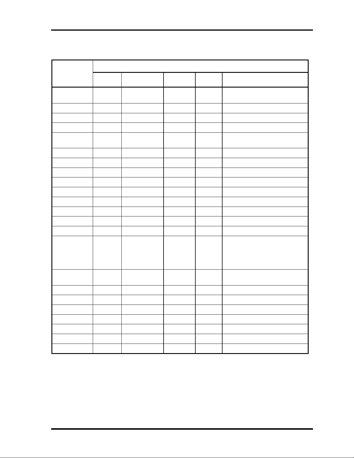
Chapter 1 Hardware Overview
Table 1-9 Power supply output rating
Power supply (Yes/No)
Name
Voltage
[V]
Power OFF
Suspend mode
Power OFF
Boot mode
No
Battery
Object
VCC_CORE
1.484 -
0.748
No No No CPU
VTT 1.05 No No No CPU, GMCH, ICH4-M
+1.8V 1.8 No No No CPU
1.2VCCT 1.35 No No No GMCH
SMDDR_VTE
RM
1.25
Yes
No No DDR-SDRAM Termination
+1.5V 1.5 No No No GMCH, ICH4-M, TV Encoder
1.5V_S5 1.5
2.5VSUS 2.5
Yes Yes
Yes
No No GMCH, DDR-SDRAM
No ICH4-M
BT_POWER 3.3 No No No Bluetooth
USBPWR2 5
USBPWR3 5
USBPWR5 5
Yes
Yes
Yes
No No USB
No No USB
No No USB
+3VA 3.3 No No No Audio Codec
AVDD 5 No No No MAX9755
Clock Generator,
Thermal Sensor, Mini-PCI,
+3V 3.3 No No No
SDRAM(SPD), GMCH, ICH4-M,
FWH, LAN, TV Encoder, LCD,
PCMCIA, EC, LED
+5V 5 No No No
3VSUS 3.3
5VSUS 5
3V_S5 3.3
5V_S5 5
3V_ALWAYS 3.3
5VPCU 5
VCCRTC 2.0 -3.6
Yes
Yes
Yes Yes
Yes Yes
Yes Yes
Yes Yes
No No Card Cont, Mini-PCI, MDC
No No PC-Card, USB
No ICH4-M
No ICH4-M
No EC/KBC
No EC/KBC, System LED
Yes Yes Yes
Mini-PCI, HDD, ODD, TP,
ICH4-M, CRT, PCMCIA, FAN
ICH4-M (RTC)
1-22 [CONFIDENTIAL] Satellite L10 Maintenance Manual (960-Q01)
Page 29
Chapter 1 Hardware Overview
1.8 Batteries
The PC has the following two batteries.
Main battery
Real time clock (RTC) battery
Table 1-12 lists the specifications for these two batteries.
Table 1-70 Battery specifications
Battery Name Battery Element Output Voltage Capacity
Main battery
Real time clock
(RTC) battery
Panasonic
CGR-B/8B9BE
Lithium ion
Simplo
916-4050
ML1220EI2 Nickel hydrogen 3V 14mAh
14.4V 4,300mAh
14.8V 4,400mAh
1.8.1 Main Battery
The main battery is the primary power supply for the computer when the AC adapter is not
connected. In Standby, the main battery maintains the current status of the computer.
Satellite L10 Maintenance Manual(960-Q01) [CONFIDENTIAL] 1-23
Page 30
Chapter 1 Hardware Overview
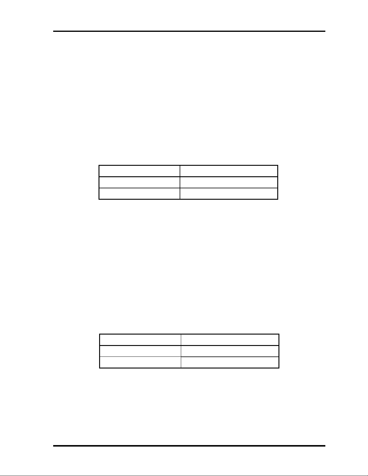
1.8.2 Battery Charging Control
Battery charging is controlled by a power supply microprocessor. The power supply
microprocessor controls power supply and detects a full charge when the AC adaptor and
battery are connected to the computer.
Battery Charge
When the AC adapter is connected, normal charging is used while the system is
turned on and quick charge is used while the system is turned off. Refer to the
following Table 1-11.
Table 1-81 Time required for charges of main battery
Condition Charging Time
Power On Charge About 6 hours
Power Off Charge About 3 hours
Charge is stopped in the following cases.
1. The main battery is fully charged
2. The main battery is removed
3. Main battery or AC adapter voltage is abnormal
4. Charging current is abnormal
Data preservation time
When turning off the power in being charged fully, the preservation time is as
following Table 1-12.
Standby About 3 days
Hibernation About 1 month
Table 1-12 Data preservation time
Condition preservation time
1-24 [CONFIDENTIAL] Satellite L10 Maintenance Manual (960-Q01)
Page 31

Chapter 1 Hardware Overview
1.8.3 RTC Battery
The RTC battery provides the power supply to maintain the date, time, and other system
information in memory.
Table 1-13 lists the Time required for charges of RTC battery and data preservation time.
Table 1-93 Time required for charges of RTC battery
Condition Time
Power ON (Lights Power LED) About 24 hours
Data preservation tome (Full-charged) About a month
Satellite L10 Maintenance Manual(960-Q01) [CONFIDENTIAL] 1-25
Page 32

Chapter 1 Hardware Overview
1.9 AC Adapter
The AC adapter is used to charge the battery.
Table 1-14 lists the AC adapter specifications.
Table 1-14 AC adapter specifications
Parameter
Power 65W
Input voltage AC 100V/240V
Input frequency 50Hz/60Hz
Input current
Output voltage DC 19V
Output current 3.42A
DELTA
SADP-65KB BFG
≦ 1.5A ≦ 1.8A
Specification
LITE-ON
PA-1650-02QT
1-26 [CONFIDENTIAL] Satellite L10 Maintenance Manual (960-Q01)
Page 33

Chapter 2
Troubleshooting Procedures
[CONFIDENTIAL]
Page 34

2
2-ii [CONFIDENTIAL] Satellite L10 Maintenance Manual(960-Q01)
Page 35

Chapter 2 Contents
2.1 Troubleshooting......................................................................................................... 2-1
2.2 Troubleshooting Flowchart........................................................................................2-3
2.3 Power Supply Troubleshooting..................................................................................2-7
Procedure 1 Power Status Check ............................................................... 2-7
Procedure 2 Error Code Check ..................................................................2-9
Procedure 3 Connection Check................................................................2-10
Procedure 4 Charging Check ................................................................... 2-10
Procedure 5 Replacement Check ............................................................. 2-11
2.4 System Board Troubleshooting................................................................................2-12
Procedure 1 Message Check .................................................................... 2-12
Procedure 2 Debugging Port Check.........................................................2-14
Procedure 3 Diagnostic Test Program Execution Check.........................2-19
Procedure 4 Replacement Check ............................................................. 2-19
2.5 USB FDD Troubleshooting .....................................................................................2-20
Procedure 1 FDD Head Cleaning Check ................................................. 2-20
Procedure 2 Diagnostic Test Program Execution Check.........................2-21
Procedure 3 Connector Check and Replacement Check..........................2-22
2.6 2.5” HDD Troubleshooting...................................................................................... 2-24
Procedure 1 Partition Check.....................................................................2-24
Procedure 2 Message Check .................................................................... 2-25
Procedure 3 Format Check.......................................................................2-26
Procedure 4 Diagnostic Test Program Execution Check.........................2-27
Procedure 5 Connector Check and Replacement Check..........................2-28
2.7 Keyboard Troubleshooting ......................................................................................2-29
Procedure 1 Diagnostic Test Program Execution Check.........................2-29
Procedure 2 Connector Check and Replacement Check..........................2-30
2.8 Touch pad Troubleshooting..................................................................................... 2-31
Procedure 1 Diagnostic Test Program Execution Check.........................2-31
Procedure 2 Connector Check and Replacement Check..........................2-32
Satellite L10 Maintenance Manual(960-Q01) [CONFIDENTIAL] 2-iii
Page 36

2.9 Display Troubleshooting.......................................................................................... 2-33
Procedure 1 External Monitor Check....................................................... 2-33
Procedure 2 Diagnostic Test Program Execution Check.........................2-33
Procedure 3 Connector and Cable Check.................................................2-34
Procedure 4 Replacement Check .............................................................2-35
2.10 Optical Disk Drive Troubleshooting........................................................................2-36
Procedure 1 Diagnostic Test Program Execution Check.........................2-36
Procedure 2 Connector Check and Replacement Check..........................2-36
2.11 Modem Troubleshooting..........................................................................................2-37
Procedure 1 Diagnostic Test Program Execution Check.........................2-37
Procedure 2 Connector Check and Replacement Check..........................2-37
2.12 LAN Troubleshooting..............................................................................................2-39
Procedure 1 Diagnostic Test Program Execution Check.........................2-39
Procedure 2 Connector Check and Replacement Check..........................2-39
2.13 Wireless LAN Troubleshooting............................................................................... 2-40
Procedure 1 Transmitting-Receiving Check............................................ 2-40
Procedure 2 Antennas' Connection Check............................................... 2-41
Procedure 3 Replacement Check ............................................................. 2-42
2.14 Sound Troubleshooting............................................................................................2-43
Procedure 1 Diagnostic Test Program Execution Check.........................2-43
Procedure 2 Connector Check.................................................................. 2-43
Procedure 3 Replacement Check ............................................................. 2-44
2-iv [CONFIDENTIAL] Satellite L10 Maintenance Manual(960-Q01)
Page 37

Chapter 2 Troubleshooting Procedures
2
2.1 Troubleshooting
Chapter 2 describes how to determine which Field Replaceable Unit (FRU) in the computer
is causing the computer to malfunction. (The “FRU” means the replaceable unit in the field.)
The FRUs covered are:
1. Power supply 6. Touch pad 11. Wireless LAN
2. System Board 7. Display 12. Sound
3. USB FDD 8. Optical Disk Drive
4. 2.5” HDD 9. Modem
5. Keyboard 10. LAN
The Test Program operations are described in Chapter 3. Detailed replacement procedures are
described in Chapter 4.
NOTE: After replacing the system board or CPU, it is necessary to execute the subtest 01
initial configuration of the 3.3 Setting of the hardware configuration in Chapter
3. Also update with the latest BIOS as described in Appendix G “BIOS Rewrite
Procedures”
After replacing the LCD, update with the latest EC/KBC as described in
Appendix H “EC/KBC Rewrite Procedures” to set the SVP parameter.
The implement for the Diagnostics procedures is referred to Chapter 3. Also, following
implements are necessary:
1. Phillips screwdrivers (For replacement procedures)
2. Implements for debugging port check
•
Toshiba MS-DOS system FD
•
RS-232C cross cable
•
Test board with debug port test cable
•
PC for displaying debug port test result
Satellite L10 Maintenance Manual (960-Q01) [CONFIDENTIAL]
2-1
Page 38

Chapter 2 Troubleshooting Procedures
There are following two types of connections in the figure of board and module connection in
and after 2.3 Power Supply Troubleshooting.
(1) Cable connection is described in the figure as line.
(2) Pin connection is described in the figure as arrow.
<e.g> Connection of modem
2-2 [CONFIDENTIAL] Satellite L10 Maintenance Manual (960-Q01)
Page 39

Chapter 2 Troubleshooting Procedures
2.2 Troubleshooting Flowchart
Use the flowchart in Figure 2-1 as a guide for determining which troubleshooting procedures
to execute. Before going through the flowchart steps, verify the following:
Ask him or her to enter the password if a password is registered.
Verify with the customer that Toshiba Windows is installed on the hard disk. Non-
Windows operating systems can cause the computer to malfunction.
Make sure all optional equipment is removed from the computer.
Satellite L10 Maintenance Manual (960-Q01) [CONFIDENTIAL]
2-3
Page 40

Chapter 2 Troubleshooting Procedures
Figure 2-1 Troubleshooting flowchart (1/2)
2-4 [CONFIDENTIAL] Satellite L10 Maintenance Manual (960-Q01)
Page 41

Chapter 2 Troubleshooting Procedures
Figure 2-1 Troubleshooting flowchart (2/2)
Satellite L10 Maintenance Manual (960-Q01) [CONFIDENTIAL]
2-5
Page 42

Chapter 2 Troubleshooting Procedures
If the diagnostics program cannot detect an error, the problem may be intermittent. The Test
program should be executed several times to isolate the problem. Check the Log Utilities
function to confirm which diagnostic test detected an error(s), then perform the appropriate
troubleshooting procedures as follows:
1. If an error is detected on the system test, memory test, display test, CD-ROM/DVD-
ROM test, expansion test, real timer test, sound test or Modem/LAN/Bluetooth
/IEEE1394 test, perform the System Board Troubleshooting Procedures in Section 2.4.
2. If an error is detected on the floppy disk test, perform the USB FDD Troubleshooting
Procedures in Section 2.5.
3. If an error is detected on the hard disk test, perform the HDD Troubleshooting
Procedures in Section 2.6.
4. If an error is found on the keyboard test (DIAGNOSTICS TEST) and pressed key
display test (ONLY ONE TEST), perform the Keyboard Troubleshooting Procedures
in Section 2.7.
5. If an error is found on the touch pad test (ONLY ONE TEST), perform the touch pad
Troubleshooting Procedures in Section 2.8.
6. If an error is detected on the display test, perform the Display Troubleshooting
Procedures in Section 2.9.
7. If an error is detected on the CD-ROM/DVD-ROM test, perform the Optical Disk
Drive Troubleshooting Procedures in Section 2.10.
8. If an error is detected on the modem test, perform the Modem Troubleshooting
Procedures in Section 2.11.
9. If an error is detected on the LAN test, perform the LAN Troubleshooting Procedures
in Section 2.12.
10. If an error is detected on the wireless LAN test, perform the Wireless LAN
Troubleshooting Procedures in Section 2.13.
11. If an error is detected on the sound test, perform the Sound Troubleshooting
Procedures in Section 2.14.
12. If an error is detected on the TV tuner test, perform the TV tuner Troubleshooting
Procedures in Section 2.15.
2-6 [CONFIDENTIAL] Satellite L10 Maintenance Manual (960-Q01)
Page 43

Chapter 2 Troubleshooting Procedures
2.3 Power Supply Troubleshooting
The power supply controller controls many functions and components. To determine if the
power supply is functioning properly, start with Procedure 1 and continue with the other
Procedures as instructed. The procedures described in this section are:
Procedure 1: Power Status Check
Procedure 2: Connection Check
Procedure 3: Charging Check
Procedure 4: Replacement Check
Procedure 1 Power Status Check
The following LED indicate the power supply status:
Battery LED
DC IN LED
The Power Supply control displays the power supply status with the Battery LED and the DC
IN LED as listed in the tables below.
Table 2-1 Battery icon
Battery icon Power supply status
Lights orange Battery is charged and the external DC is input. It has no
relation with ON/OFF of the system power.
Lights green Battery is fully charged and the external DC is input. It has
no relation with ON/OFF of the system power.
Blinks orange
(even intervals)
Blinks orange once
(at being switched on)
Doesn’t light Any condition other than those above.
The battery level is low while the system power is ON.
The system is driven by only a battery and the battery level
is low.
Satellite L10 Maintenance Manual (960-Q01) [CONFIDENTIAL]
2-7
Page 44

Chapter 2 Troubleshooting Procedures
Table 2-2 DC IN icon
DC IN icon Power supply status
Lights green DC power is being sup plied from the AC adapter.
Doesn’t light Any condition other than those above.
*1 When the power supply controller detects a malfunction, the DC IN icon blinks
orange. It shows an error code.
When the icon is blinking, perform the following procedure.
1. Remove the battery pack and the AC adapter.
2. Re-attach the battery pack and the AC adapter.
If the icon is still blinking after the operation above, check the followings:
Check 1 If the DC IN icon does not light, go to Procedure 2.
Check 2 If the battery icon does not light orange or green, go to Procedure 3.
NOTE: Use a supplied AC adapter.
2-8 [CONFIDENTIAL] Satellite L10 Maintenance Manual (960-Q01)
Page 45

Chapter 2 Troubleshooting Procedures
Procedure 2 Connection Check
The wiring diagram related to the power supply is shown below:
Any of the connectors may be disconnected. Perform Check 1.
Check 1 Make sure the AC adapter and the AC power cord are firmly plugged into the DC
IN socket (CN13) and wall outlet. If these cables are connected firmly, go to
Check 2.
Check 2 Replace the AC adapter and the AC power cord with new ones.
• If the DC IN icon does not light, go to Procedure 4.
• If the battery icon does not light, go to Check 3.
Check 3 Make sure the battery pack is installed in the computer correctly. If the battery is
properly installed and the battery icon still does not light, go to Procedure 4.
Procedure 3 Charging Check
Check if the power supply controller charges the battery pack properly. Perform the
following procedures:
Check 1 Make sure the AC adapter is firmly plugged into the DC IN socket (CN13).
Check 2 Make sure the battery pack is properly installed. If it is properly installed, go to
Check 3.
Check 3 The battery pack may be completely discharged. Wait a few minutes to charge the
battery pack while connecting the battery pack and the AC adapter. If the battery
pack is still not charged, go to Check 4.
Check 4 The battery’s temperature is too high or low. Leave the battery for a while to
adjust it in the right temperature. If the battery pack is still not charged, go to
Check 5.
Check 5 Replace the battery pack with a new one. If the battery pack is still not charged,
go to Procedure 4.
Satellite L10 Maintenance Manual (960-Q01) [CONFIDENTIAL]
2-9
Page 46

Chapter 2 Troubleshooting Procedures
Procedure 4 Replacement Check
The power is supplied to the system board by the AC adapter. If either the AC adapter or the
system board was damaged, perform the following Checks.
To disassemble the computer, follow the steps described in Chapter 4, Replacement
Procedures.
When AC adapter is connected ;
Check 1 AC adapter may be faulty. Replace the AC adapter with a new one. If the problem
still occurs, perform Check 2.
Check 2 System board may be faulty. Replace the system board with a new one.
When AC adapter is not connected ;
(When driving with battery pack)
Check 1 Battery pack may be faulty. Replace it with a new one. If the problem still occurs,
perform Check 2.
Check 2 System board may be faulty. Replace it with a new one.
2-10 [CONFIDENTIAL] Satellite L10 Maintenance Manual (960-Q01)
Page 47

Chapter 2 Troubleshooting Procedures
2.4 System Board Troubleshooting
This section describes how to determine if the system board is malfunctioning or not. Start
with Procedure 1 and continue with the other procedures as instructed. The procedures
described in this section are:
Procedure 1: Message Check
Procedure 2: Debugging Port Check
Procedure 3: Diagnostic Test Program Execution Check
Procedure 4: Replacement Check
Satellite L10 Maintenance Manual (960-Q01) [CONFIDENTIAL]
2-11
Page 48

Chapter 2 Troubleshooting Procedures
Procedure 1 Message Check
When the power is turned on, the system performs the Power On Self Test (POST) installed
in the BIOS ROM. The POST tests each IC on the system board and initializes it.
If an error message is shown on the display, perform Check 1.
If there is no error message, go to Procedure 2.
If MS-DOS or Windows XP is properly loaded, go to Procedure 4.
Check 1 If one of the following error messages is displayed on the screen, press the F1 key
as the message instructs. These errors occur when the system configuration
preserved in the RTC memory (CMOS type memory) is not the same as the actual
configuration or when the data is lost.
If you press the F1 key as the message instructs, the SETUP screen appears to set
the system configuration. If error message (b) appears often when the power is
turned on, replace the RTC battery. If any other error message is displayed,
perform Check 2.
(a) *** Bad HDD type ***
Check system. Then press [F1] key ......
(b) *** Bad RTC battery ***
Check system. Then press [F1] key ......
(c) *** Bad configuration ***
Check system. Then press [F1] key ......
(d) *** Bad memory size ***
Check system. Then press [F1] key ......
(e) *** Bad time function ***
Check system. Then press [F1] key ......
(f) *** Bad check sum (CMOS) ***
Check system. Then press [F1] key ......
(g) *** Bad check sum (ROM) ***
Check system. Then press [F1] key ......
Check 2 If the following error message is displayed on the screen, press any key as the
message instructs.
The following error message appears when data stored in RAM under the resume
function is lost because the battery has become discharged or the system board is
damaged. Go to Procedure 3.
WARNING: RESUME FAILURE.
PRESS ANY KEY TO CONTINUE.
If any other error message displays, perform Check 3.
2-12 [CONFIDENTIAL] Satellite L10 Maintenance Manual (960-Q01)
Page 49

Chapter 2 Troubleshooting Procedures
Check 3 The IRT checks the system board. When the IRT detects an error, the system
stops or an error message appears.
If one of the following error messages (1) through (17), (24) or (25) is displayed,
go to Procedure 4.
If error message (18) is displayed, go to the Keyboard Troubleshooting
Procedures.
If error message (19), (20) or (21) is displayed, go to the 2.5” HDD
Troubleshooting Procedures.
If error message (22) or (23) is displayed, go to the USB FDD Troubleshooting
Procedures.
(1) PIT ERROR
(2) MEMORY REFRESH ERROR
(3) TIMER CH.2 OUT ERROR
(4) CMOS CHECKSUM ERROR
(5) CMOS BAD BATTERY ERROR
(6) FIRST 64KB MEMORY ERROR
(7) FIRST 64KB MEMORY PARITY ERROR
(8) VRAM ERROR
(9) SYSTEM MEMORY ERROR
(10) SYSTEM MEMORY PARITY ERROR
(11) EXTENDED MEMORY ERROR
(12) EXTENDED MEMORY PARITY ERROR
(13) DMA PAGE REGISTER ERROR
(14) DMAC #1 ERROR
(15) DMAC #2 ERROR
(16) PIC #1 ERROR
(17) PIC #2 ERROR
(18) KBC ERROR
(19) HDC ERROR
(20) HDD #0 ERROR
(21) HDD #1 ERROR
(22) NO FDD ERROR
(23) FDC ERROR
(24) TIMER INTERRUPT ERROR
(25) RTC UPDATE ERROR
Satellite L10 Maintenance Manual (960-Q01) [CONFIDENTIAL]
2-13
Page 50

Chapter 2 Troubleshooting Procedures
Procedure 2 Debugging Port Check
Check the MiniPCI Debug board. The tool for debug port test is shown below.
Figure 2-2 A set of tool for debug port test
The test procedures are follows:
1. Replace MiniPCI debug port with Wireless LAN card, check LED in the miniPCI
debug board
The following is a list of the Test Point codes written to port 80h at the start
of each routine, the beep codes issued for terminal errors, and a description
of the POST routine. Unless otherwise noted, these codes are valid for
PhoenixBIOS 4.0 Release 6.0.
NOTE: The following routines are sorted by their test point numbers
assigned in the BIOS code. Their actual order as executed during POST can
be quite different.
Code Beeps POST Routine Description
02h Verify Real Mode
03h Disable Non-Maskable Interrupt (NMI)
04h Get CPU type
06h Initialize system hardware
08h Initialize chipset with initial POST values
09h Set IN POST flag
0Ah Initialize CPU registers
0Bh Enable CPU cache
0Ch Initialize caches to initial POST values
0Eh Initialize I/O component
0Fh Initialize the local bus IDE
10h Initialize Power Management
11h Load alternate registers with initial POST values
12h Restore CPU control word during warm boot
13h Initialize PCI Bus Mastering devices
2-14 [CONFIDENTIAL] Satellite L10 Maintenance Manual (960-Q01)
Page 51

Chapter 2 Troubleshooting Procedures
Code Beeps POST Routine Description
14h Initialize keyboard controller
16h 1-2-2-3 BIOS ROM checksum
17h Initialize cache before memory autosize
18h 8254 timer initialization
1Ah 8237 DMA controller initialization
1Ch Reset Programmable Interrupt Controller
20h 1-3-1-1 Test DRAM refresh
22h 1-3-1-3 Test 8742 Keyboard Controller
24h Set ES segment register to 4 GB
26h Enable A20 line
28h Autosize DRAM
29h Initialize POST Memory Manager
2Ah Clear 512 KB base RAM
2Ch 1-3-4-1 RAM failure on address line xxxx*
2Eh 1-3-4-3 RAM failure on data bits xxxx* of low byte of memory bus
2Fh Enable cache before system BIOS shadow
30h 1-4-1-1 RAM failure on data bits xxxx* of high byte of memory bus
32h Test CPU bus-clock frequency
33h Initialize Phoenix Dispatch Manager
36h Warm start shut down
38h Shadow system BIOS ROM
3Ah Autosize cache
3Ch Advanced configuration of chipset registers
3Dh Load alternate registers with CMOS values
42h Initialize interrupt vectors
45h POST device initialization
46h 2-1-2-3 Check ROM copyright notice
48h Check video configuration against CMOS
49h Initialize PCI bus and devices
4Ah Initialize all video adapters in system
4Bh QuietBoot start (optional)
4Ch Shadow video BIOS ROM
4Eh Display BIOS copyright notice
50h Display CPU type and speed
51h Initialize EISA board
52h Test keyboard
54h Set key click if enabled
58h 2-2-3-1 Test for unexpected interrupts
59h Initialize POST display service
5Ah Display prompt "Press F2 to enter SETUP"
5Bh Disable CPU cache
5Ch Test RAM between 512 and 640 KB
60h Test extended memory
62h Test extended memory address lines
64h Jump to UserPatch1
Satellite L10 Maintenance Manual (960-Q01) [CONFIDENTIAL]
2-15
Page 52

Chapter 2 Troubleshooting Procedures
66h Configure advanced cache registers
67h Initialize Multi Processor APIC
68h Enable external and CPU caches
69h Setup System Management Mode (SMM) area
6Ah Display external L2 cache size
6Bh Load custom defaults (optional)
6Ch Display shadow-area message
6Eh Display possible high address for UMB recovery
70h Display error messages
72h Check for configuration errors
76h Check for keyboard errors
7Ch Set up hardware interrupt vectors
7Eh Initialize coprocessor if present
80h Disable onboard Super I/O ports and IRQs
81h Late POST device initialization
82h Detect and install external RS232 ports
83h Configure non-MCD IDE controllers
84h Detect and install external parallel ports
85h Initialize PC-compatible PnP ISA devices
86h Re-initialize onboard I/O ports.
87h Configure Motheboard Configurable Devices (optional)
88h Initialize BIOS Data Area
89h Enable Non-Maskable Interrupts (NMIs)
8Ah Initialize Extended BIOS Data Area
8Bh Test and initialize PS/2 mouse
8Ch Initialize floppy controller (optional)
8Fh Determine number of ATA drives (optional)
90h Initialize hard-disk controllers
91h Initialize local-bus hard-disk controllers
92h Jump to UserPatch2
93h Build MPTABLE for multi-processor boards
95h Install CD ROM for boot
96h Clear huge ES segment register
97h Fixup Multi Processor table
98h 1-2 Search for option ROMs. One long, two short beeps on checksum failure
99h Check for SMART Drive (optional)
9Ah Shadow option ROMs
9Ch Set up Power Management
9Dh Initialize security engine (optional)
9Eh Enable hardware interrupts
9Fh Determine number of ATA and SCSI drives
A0h Set time of day
A2h Check key lock
A4h Initialize Typematic rate
A8h Erase F2 prompt
2-16 [CONFIDENTIAL] Satellite L10 Maintenance Manual (960-Q01)
Page 53

Chapter 2 Troubleshooting Procedures
Code Beeps POST Routine Description
AAh Scan for F2 key stroke
ACh Enter SETUP
AEh Clear Boot flag
B0h Check for errors
B2h POST done - prepare to boot operating system
B4h 1 One short beep before boot
B5h Terminate QuietBoot (optional)
B6h Check password (optional)
B9h Prepare Boot
Bah Initialize DMI parameters
BBh Initialize PnP Option ROMs
BCh Clear parity checkers
BDh Display MultiBoot menu
BEh Clear screen (optional)
BFh Check virus and backup reminders
C0h Try to boot with INT 19
C1h Initialize POST Error Manager (PEM)
C2h Initialize error logging
C3h Initialize error display function
C4h Initialize system error handler
C5h PnPnd dual CMOS (optional)
C6h Initialize notebook docking (optional)
C7h Initialize notebook docking late
C8h Force check (optional)
C9h Extended checksum (optional)
D2h Unknown interrupt
Satellite L10 Maintenance Manual (960-Q01) [CONFIDENTIAL]
2-17
Page 54

Chapter 2 Troubleshooting Procedures
Code Beeps For Boot Block in Flash ROM
E0h Initialize the chipset
E1h Initialize the bridge
E2h Initialize the CPU
E3h Initialize system timer
E4h Initialize system I/O
E5h Check force recovery boot
E6h Checksum BIOS ROM
E7h Go to BIOS
E8h Set Huge Segment
E9h Initialize Multi Processor
EAh Initialize OEM special code
EBh Initialize PIC and DMA
ECh Initialize Memory type
EDh Initialize Memory size
EEh Shadow Boot Block
EFh System memory test
F0h Initialize interrupt vectors
F1h Initialize Run Time Clock
F2h Initialize video
F3h Initialize System Management Mode
F4h 1 Output one beep before boot
F5h Boot to Mini DOS
F6h Clear Huge Segment
F7h Boot to Full DOS
2-18 [CONFIDENTIAL] Satellite L10 Maintenance Manual (960-Q01)
Page 55

Chapter 2 Troubleshooting Procedures
Procedure 3 Diagnostic Test Program Execution Check
Execute the following tests from the Diagnostic Test Menu. These tests check the system
board. Refer to Chapter 3, Tests and Diagnostic, for more information on how to perform
these tests.
1. System test
2. Memory test
3. Keyboard test
4. Display test
5. Floppy Disk test [It is not supported]
6. Printer test [It is not supported]
7. Async test [It is not supported]
8. Hard Disk test
9. Real Timer test
10. NDP test
11. Expansion test
12. CD-ROM/DVD-ROM test
13. Only One test
14. Wireless LAN test
15. LAN/ModemSound test
If an error is detected during these tests, go to Procedure 4.
Procedure 4 Replacem ent Check
System board may be faulty. Disassemble the computer following the steps described in
Chapter 4, Replacement Procedures and replace system board with a new one.
Satellite L10 Maintenance Manual (960-Q01) [CONFIDENTIAL]
2-19
Page 56

Chapter 2 Troubleshooting Procedures
2.5 USB FDD Troubleshooting
To check if the USB FDD is malfunctioning or not, follow the troubleshooting procedures
below as instructed.
Procedure 1: FDD Head Cleaning Check
Procedure 2: Diagnostic Test Program Execution Check
Procedure 3: Connector Check and Replacement Check
Procedure 1 FDD Head Cleaning Check
FDD head cleaning is one option available in the Diagnostic Program.
After connecting USB FDD, insert the Diagnostics Disk in the floppy disk drive. Turn on the
computer and run the test. And then clean the FDD heads using the cleaning kit. If the FDD
still does not function properly after cleaning, go to Procedure 2.
Detailed operation is given in Chapter 3, Tests and Diagnostics.
If the test program cannot be executed on the computer, go to Procedure 3.
2-20 [CONFIDENTIAL] Satellite L10 Maintenance Manual (960-Q01)
Page 57

Chapter 2 Troubleshooting Procedures
Procedure 2 Diagnostic Test Program Execution Check
Insert the Diagnostics Disk in the USB FDD, turn on the computer and run the test. Refer to
Chapter 3, Tests and Diagnostics, for more information about the diagnostics test procedures.
Make sure the floppy disk is formatted correctly and that the write protect tab is disabled.
Floppy disk drive test error codes and their status names are listed in Table 2-7. If any other
errors occur while executing the FDD diagnostics test, go to Check 1.
Table 2-7 FDD error code and status
Code Status
01h Bad command
02h Address mark not found
03h Write protected
04h Record not found
06h Media replaced
08h DMA overrun error
09h DMA boundary error
10h CRC error
20h FDC error
40h Seek error
60h FDD not drive
80h Time out error (Not ready)
EEh Write buffer error
FFh Data compare error
Check 1 If the following message is displayed, disable the write protect tab on the floppy
disk by sliding the write protect tab to “write enable”. If any other message
appears, perform Check 2.
Write protected
Check 2 Make sure the floppy disk is formatted correctly. If it is, go to Procedure 3.
Satellite L10 Maintenance Manual (960-Q01) [CONFIDENTIAL]
2-21
Page 58

Chapter 2 Troubleshooting Procedures
Procedure 3 Connector Check and Replacement Check
USB FDD is connected to USB port on system board and US board. US board is also
connected to system board by cable. The connection of cable and board may be defective.
Otherwise, they may be faulty. Disassemble the computer following the steps described in
Chapter 4, Replacement Procedures and perform the following checks.
USB FDD can be connected to the following 3 ports.
(System board x 3 ports, US board x 1 port )
Check 1 Make sure USB FDD is firmly connected to USB port. If the connection is loose,
connect firmly and repeat Procedure 2. If the problem still occurs, go to Check 2.
NOTE: When checking the connection, be sure to check it with care for the followings.
1. Cable can not be disconnected from the connector.
2. Cable is connected straight to the connector.
3. Cable is connected all the way seated in the connector.
4. Cable can not be broken.
2-22 [CONFIDENTIAL] Satellite L10 Maintenance Manual (960-Q01)
Page 59

Chapter 2 Troubleshooting Procedures
Check 2 USB FDD may be faulty. Replace it with a new one. If the problem still occurs,
perform Check 3.
Check 3 Connect USB FDD to each port embedded on system board . If it does not work
properly when connected to CN14, CN19, CN22 or all ports, perform Check 4.
Check 4 System board may be faulty. Replace it with a new one following the steps in
Chapter 4, Replacement Procedures.
Satellite L10 Maintenance Manual (960-Q01) [CONFIDENTIAL]
2-23
Page 60

Chapter 2 Troubleshooting Procedures
2.6 2.5” HDD Troubleshooting
To check if 2.5” HDD is malfunctioning or not, follow the troubleshooting procedures below
as instructed.
Procedure 1: Partition Check
Procedure 2: Message Check
Procedure 3: Format Check
Procedure 4: Diagnostic Test Program Execution Check
Procedure 5: Connector Check and Replacement Check
CAUTION: The contents of the hard disk will be erased when the 2.5” HDD
troubleshooting procedures are executed. Transfer the contents of the hard
disk to floppy disks or other storage drive(s). For the backup, refer to the
User’s Manual.
Procedure 1 Partition Check
Insert the Toshiba MS-DOS system disk and start the computer. Perform the following
checks:
Check 1 Input C: and press Enter. If you cannot change to drive C, go to Check 2. If you
can change to drive C, go to Procedure 2.
Check 2 Input FDISK and press Enter. Choose Display Partition Information from the
FDISK menu. If drive C is listed in the Display Partition Information, go to Check
3. If drive C is not listed, return to the FDISK menu and choose the option to
create a DOS partition or a logical DOS drive on drive C. If the problem still
occurs, go to Procedure 2.
Check 3 If drive C is listed as active in the FDISK menu, go to Check 4. If drive C is not
listed as active, return to the FDISK menu and choose the option to set the active
partition for drive C. Then go to Procedure 2.
Check 4 Remove the system disk from the FDD and reboot the computer. If the problem
still occurs, go to Procedure 2. Otherwise, the 2.5” HDD is operating normally.
2-24 [CONFIDENTIAL] Satellite L10 Maintenance Manual (960-Q01)
Page 61

Chapter 2 Troubleshooting Procedures
Procedure 2 Message Check
When the power is turned on, the system performs the Initial Reliability Test (IRT) installed
in the BIOS ROM. When the test detects an error, an error message is displayed on the screen.
Make sure no floppy disk is in the FDD. Turn on the computer and check the message on the
screen. When an OS starts from the 2.5” HDD, go to Procedure 3. Otherwise, start with
Check 1 below and perform the other checks as instructed.
Check 1 If any of the following messages appear, go to Procedure 3. If the following
messages do not appear, perform Check 2.
HDC ERROR
or
HDD #X ERROR (After 5 seconds this message will disappear.)
Check 2 If either of the following messages appears, go to Check 3. If the following
messages do not appear, perform Check 4.
Insert system disk in drive
Press any key when ready .....
or
Non-System disk or disk error
Replace and press any key when ready
Check 3 Using the SYS command of the MS-DOS, transfer the system to the 2.5” HDD. If
the system is not transferred, go to Procedure 3. Refer to the MS-DOS Manual for
detailed operation.
If the following message appears on the display, the system program has been
transferred to the HDD.
System Transferred
If an error message appears on the display, perform Check 4.
Check 4 2.5” HDD(s) and the connector(s) of system board may be defective (Refer to the
steps described in Chapter 4, Replacement Procedures for disassembling.). Insert
HDD(s) to the connector(s) firmly. If it is (or they are) firmly connected, go to
Procedure 3.
Satellite L10 Maintenance Manual (960-Q01) [CONFIDENTIAL]
2-25
Page 62

Chapter 2 Troubleshooting Procedures
Procedure 3 Format Check
The computer’s HDD is formatted using the MS-DOS FORMAT program or the physical
format program of the test program. To format the HDD, start with Check 1 below and
perform the other steps as required.
Refer to the MS-DOS Manual for the operation of MS-DOS. For the format by the test
program, refer to the Chapter 3.
Check 1 Format an 2.5” HDD using MS-DOS FORMAT command. Type as FORMAT
C:/S/U.
If 2.5” HDD can not be formatted, perform Check 2.
Check 2 Using the MS-DOS FDISK command, set the 2.5” HDD partition. If the partition
is not set, go to Check 3. If it is set, format 2.5” HDD using MS-DOS FORMAT
command.
Check 3 Using the Diagnostic Disk, format 2.5” HDD with a format option (physical
format). If HDD is formatted, set the 2.5” HDD partition using MS-DOS FDISK
command.
If you cannot format 2.5” HDD using the Tests and Diagnostic program, go to
Procedure 4.
2-26 [CONFIDENTIAL] Satellite L10 Maintenance Manual (960-Q01)
Page 63

Chapter 2 Troubleshooting Procedures
Procedure 4 Diagnostic Test Program Execution Check
The HDD test program is stored in the Diagnostics Disk. Perform all of the HDD tests in the
Hard Disk Drive Test. Refer to Chapter 3, Tests and Diagnostics, for more information about
the HDD test program.
If an error is detected during the HDD test, an error code and status will be displayed. The
error codes and statuses are described in Table 2-8. If an error code is not displayed but the
problem still occurs, go to Procedure 5.
Table 2-8 2.5” Hard disk drive error code and status
Code Status
05 HDD - HDC NOT RESET ERROR
07 HDD - DRIVE NOT INITIALIZE
09 HDD - DMA BOUNDARY ERROR
0B HDD - BAD TRACK ERROR
BB HDD - UNDEFINED ERROR
08 HDD - OVERRUN ERROR (DRQ ON)
01 HDD - BAD COMMAND ERROR
02 HDD - ADDRESS MARK NOT FOUND
04 HDD - RECORD NOT FOUND ERROR
10 HDD - ECC ERROR
20 HDD - HDC ERROR
40 HDD - SEEK ERROR
80 HDD - TIME OUT ERROR
11 HDD - ECC RECOVER ENABLE
AA HDD - DRIVE NOT READY
CC HDD - WRITE FAULT
E0 HDD - STATUS ERROR
0A HDD - BAD SECTOR
EE HDD - ACCESS TIME ERROR
DA HDD - NO HDD
12 HDD - DMA CRC ERROR
Satellite L10 Maintenance Manual (960-Q01) [CONFIDENTIAL]
2-27
Page 64

Chapter 2 Troubleshooting Procedures
Procedure 5 Connector Check and Replacement Check
HDD(s) is/are connected to the connector(s) on the system board. The connection of HDD(s)
and board may be defective. Otherwise, they may be faulty. Disassemble the computer
following instructions in Chapter 4, Replacement Procedures and perform the following
checks.
Check 1 Make sure HDD(s) is/are firmly connected to the connector(s) on the system
board.
If any of the connections are loose, reconnect firmly and repeat Procedure 1. If the
problem still occurs, go to Check 2.
Check 2 (One of) HDD(s) may be faulty. Replace it with a new one following the
instructions in Chapter 4, Replacement Procedures and check the operation. If the
problem still occurs, perform Check 3.
Check 3 System board may be faulty. Replace it with a new one following the instructions
in Chapter 4, Replacement Procedures.
2-28 [CONFIDENTIAL] Satellite L10 Maintenance Manual (960-Q01)
Page 65

Chapter 2 Troubleshooting Procedures
2.5 2.7 Keyboard Troubleshooting
To check if the computer’s keyboard is malfunctioning or not, follow the troubleshooting
procedures below as instructed.
Procedure 1: Diagnostic Test Program Execution Check
Procedure 2: Connector and Replacement Check
Procedure 1 Diagnostic Test Program Execution Check
Execute the Keyboard Test (DIAGNOSTIC TEST) and Pressed key display test (ONLY
ONE TEST) in the Diagnostic Program. Refer to Chapter 3, Tests and Diagnostics, for more
information on how to perform the test program.
If an error occurs, go to Procedure 2. If an error does not occur, keyboard is functioning
properly.
Satellite L10 Maintenance Manual (960-Q01) [CONFIDENTIAL]
2-29
Page 66

Chapter 2 Troubleshooting Procedures
Procedure 2 Connector and Replacement Check
The connection of cable and board may be defective. Otherwise, they may be faulty.
Disassemble the computer following the steps described in Chapter 4, Replacement
Procedures, and perform the following checks:
Check 1 Make sure keyboard cable is firmly connected to system board.
If the connection is loose, reconnect firmly and repeat Procedure 1. If the problem
still occurs, go to Check 2.
Check 2 Keyboard may be faulty. Replace it with a new one following the instructions in
Chapter 4, Replacement Procedures. If the problem still occurs, perform Check 3.
Check 3 System board may be faulty. Replace it with a new one following the instructions
in Chapter 4, Replacement Procedures.
2-30 [CONFIDENTIAL] Satellite L10 Maintenance Manual (960-Q01)
Page 67

Chapter 2 Troubleshooting Procedures
2.8 Touch pad Troubleshooting
To check if the computer’s touch pad is malfunctioning or not, follow the troubleshooting
procedures below as instructed.
Procedure 1: Diagnostic Test Program Execution Check
Procedure 2: Connector and Replacement Check
Procedure 1 Diagnostic Test Program Execution Check
Execute the Touch pad test (ONLY ONE TEST) in the Diagnostic Program. Refer to Chapter
3, Tests and Diagnostics, for more information on how to perform the test program.
If an error occurs, go to Procedure 2. If an error does not occur, touch pad is functioning
properly.
Satellite L10 Maintenance Manual (960-Q01) [CONFIDENTIAL]
2-31
Page 68

Chapter 2 Troubleshooting Procedures
Procedure 2 Connector and Replacement Check
The connection of cable and board may be defective. Otherwise, they may be faulty.
Disassemble the computer following the steps described in Chapter 4, Replacement
Procedures, and perform the following checks:
Check 1 Make sure the cable is firmly connected to system board.
If the connection is loose, reconnect firmly and repeat Procedure 1. If the problem
still occurs, go to Check 2.
Check 2 Touch Pad or the cable may be faulty. Replace it with a new one following the
instructions in Chapter 4, Replacement Procedures. If the problem still occurs,
perform Check 3.
Check 3 System board may be faulty. Replace it with a new one following the instructions
in Chapter 4, Replacement Procedures.
2-32 [CONFIDENTIAL] Satellite L10 Maintenance Manual (960-Q01)
Page 69

Chapter 2 Troubleshooting Procedures
2.9 Display Troubleshooting
To check if the computer’s display is malfunctioning or not, follow the troubleshooting
procedures below as instructed.
Procedure 1: External Monitor Check
Procedure 2: Diagnostic Test Program Execution Check
Procedure 3: Connector and Cable Check
Procedure 4: Replacement Check
Procedure 1 External Monitor Check
Connect an external monitor to the computer’s external monitor port, then boot the computer.
The computer automatically detects the external monitor.
If the external monitor works correctly, the internal LCD may be faulty. Go to Procedure 3.
If the external monitor appears to have the same problem as the internal monitor, system
board may be faulty. Go to Procedure 2.
Procedure 2 Diagnostic Test Program Execution Check
The Display Test program is stored in Diagnostics disk. This program checks the display
controller on system board. Insert the Diagnostics disk in the USB FDD, turn on the computer
and run the test. Refer to Chapter 3, Tests and Diagnostics for details. If an error is detected,
go to Procedure 3.
Satellite L10 Maintenance Manual (960-Q01) [CONFIDENTIAL] 2-33
Page 70

Chapter 2Troubleshooting Procedures
Procedure 3 Connector and Cable Check
LCD Module is connected to system board by an LCD/FL cable. FL inverter board is also
connected to system board by an LCD/FL cable. And, fluorescent lamp is connected to FL
inverter board by HV cable. Their cables may be disconnected from system board or FL
inverter board. Disassemble the computer following the steps described in Chapter 4,
Replacement Procedures.
If the connection is loose, reconnect firmly and restart the computer. If the problem still
occurs, go to Procedure 4.
2-34 [CONFIDENTIAL] Satellite L10 Maintenance Manual (960-Q01)
Page 71

Chapter 2 Troubleshooting Procedures
Procedure 4 Replacem ent Check
Fluorescent lamp, FL inverter, LCD module, HV cable and LCD/FL cable are connected to
display circuits. Any of these components may be faulty. Refer to Chapter 4, Replacement
Procedures, for instructions on how to disassemble the computer and then perform the
following checks:
If fluorescent lamp does not light, perform Check 1.
If characters or graphics on the internal display are not displayed clearly, perform
Check 4.
If some screen functions do not operate properly, perform Check 4.
If fluorescent lamp remains lit when the display is closed, perform Check 5.
Check 1 Replace fluorescent lamp with a new one following the instructions in Chapter 4,
Replacement Procedures and test the display again. If the problem still occurs,
perform Check 2.
Check 2 LCD/FL cable may be faulty. Replace FL/LCD cable with a new one following the
instructions in Chapter 4, Replacement Procedure and test the display again. If the
problem still occurs, perform Check 3.
Check 3 FL inverter may be faulty. Replace FL inverter with a new one following the
instructions in Chapter 4, Replacement Procedure and test the display again. If the
problem still occurs, perform Check 4.
Check 4 LCD module may be faulty. Replace LCD module with a new one following the
instructions in Chapter 4, Replacement Procedure and test the display again. If the
problem still occurs, perform Check 5.
Check 5 System board may be faulty. Replace it with a new one following the instructions
in Chapter 4, Replacement Procedure.
Satellite L10 Maintenance Manual (960-Q01) [CONFIDENTIAL] 2-35
Page 72

Chapter 2Troubleshooting Procedures
2.10 Optical Disk Drive Troubleshooting
To check if optical disk drive is malfunctioning or not, follow the troubleshooting procedures
below as instructed.
Procedure 1: Diagnostic Test Program Execution Check
Procedure 2: Connector Check and Replacement Check
Procedure 1 Diagnostic Test Program Execution Check
Execute the CD-ROM/DVD-ROM Test in the Diagnostic Program. Refer to Chapter 3, Tests
and Diagnostics for more information on how to perform the test program.
Prepare the tools before the test.
If any error is detected by the test, go to Procedure 2.
Procedure 2 Connector Check and Replacement Check
The connection of optical disk drive and system board may be defective. Otherwise, they may
be faulty. Disassemble the computer following the steps described in Chapter 4 and perform
the following checks:
Check 1 Make sure optical disk drive is firmly connected to the connector on system board.
If the connection is loose, reconnect it firmly and return to Procedure 2. If the
problem still occurs, perform Check 2.
Check 2 Optical disk drive may be faulty. Replace it with a new one following the steps in
Chapter 4. If the problem still occurs, perform Check 3.
Check 3 System board may be faulty. Replace it with new one following the instructions in
Chapter 4.
2-36 [CONFIDENTIAL] Satellite L10 Maintenance Manual (960-Q01)
Page 73

Chapter 2 Troubleshooting Procedures
2.11 Modem Troubleshooting
To check if modem is malfunctioning or not, follow the troubleshooting procedures below as
instructed.
Procedure 1: Diagnostic Test Program Execution Check
Procedure 2: Connector Check and Replacement Check
Procedure 1 Diagnostic Test Program Execution Check
Execute Modem test in the LAN/Modem/Bluetooth/IEEE1394 test program. Refer to Chapter
3, Tests and Diagnostics for more information on how to perform the test program.
If any error is detected, perform Procedure 2.
Procedure 2 Connector Check and Replacement Check
MDC (Modem Daughter Card) is used as the modem for this computer. MDC is connected to
connected to system board by CN26. And also, MDC is connected to system board by cable.
If modem malfunctions, The connection of cable, board and module may be defective.
Otherwise, they may be faulty.
Disassemble the computer following the steps described in Chapter 4 and perform the
following checks:
Check 1 Make sure the following connections are firmly connected.
If any connector is disconnected, connect it firmly and return to Procedure 1. If the
problem still occurs, perform Check 2.
Satellite L10 Maintenance Manual (960-Q01) [CONFIDENTIAL] 2-37
Page 74

Chapter 2Troubleshooting Procedures
Check 2 Modem cable may be faulty. Replace it with a new one. If the problem still occurs,
perform Check 3.
Check 3 MDC may be faulty. Replace it with a new one following the steps in Chapter 4. If
the problem still occurs, perform Check 4.
Check 4 Cable between MDC and system board may be faulty. Replace it with a new one
following the instructions in Chapter 4. If the problem still occurs, perform Check
5.
Check 6 System board may be faulty. Replace it with a new one following the instruction in
Chapter 4.
2-38 [CONFIDENTIAL] Satellite L10 Maintenance Manual (960-Q01)
Page 75

Chapter 2 Troubleshooting Procedures
2.12 LAN Troubleshooting
To check if the computer’s LAN is malfunctioning or not, follow the troubleshooting
procedures below as instructed.
Procedure 1: Diagnostic Test Program Execution Check
Procedure 2: Connector Check and Replacement Check
Procedure 1 Diagnostic Test Program Execution Check
Execute LAN test in the LAN/Modem test program. Refer to Chapter 3, Tests and Diagnostics
for more information on how to perform the test program.
If any error is detected by the test, go to Procedure 2.
Procedure 2 Connector Check and Replacement Check
The LAN function is embedded on system board. If LAN malfunctions, its connection is
defective or LAN cable and system board may be faulty.
Check 1 Make sure LAN cable is firmly connected to the connector CN1. If the problem
still occurs, perform Check 2.
Check 2 LAN cable may be faulty. Replace it with a new one. If the problem still occurs,
perform Check 3.
Check 3 System board may be faulty. Replace it with a new one following the instruction in
Chapter 4.
Satellite L10 Maintenance Manual (960-Q01) [CONFIDENTIAL] 2-39
Page 76

Chapter 2Troubleshooting Procedures
2.13 Wireless LAN Troubleshooting
To check if the computer's Wireless LAN is malfunctioning or not, follow the troubleshooting
procedures below as instructed.
Procedure 1: Transmitting-Receiving Check
Procedure 2: Antennas' Connection Check
Procedure 3: Replacement Check
Procedure 1 Transmitting-Receiving Check
Before starting the test, make sure the wireless communication switch is set in the ON
position.
Check 1 Execute Wireless LAN test program to check the transmitting-receiving function
of wireless LAN. You will need a second computer that can communicate by
wireless LAN. Perform the test following the instructions described in Chapter 3.
If the computer passes the test, the function is correctly working. If the computer
does not pass the test, perform Procedure 2.
2-40 [CONFIDENTIAL] Satellite L10 Maintenance Manual (960-Q01)
Page 77

Chapter 2 Troubleshooting Procedures
Procedure 2 Antennas' Connectio n Check
The wireless LAN function-wiring diagram is shown below:
Any of the connections may be defective. Disassemble the computer following the steps
described in Chapter 4, Replacement Procedures, and perform the following checks:
Check 1 Make sure the wireless communication switch is “On”.
If the switch is “Off”, turn it “On”. If the problem still occurs, perform Check 2.
Check 2 Make sure wireless LAN card (Mini-PCI) is firmly connected to the CN2200 on
system board. If the connector is defective, connect it firmly and perform
Procedure 1. If the problem still occurs, perform Check 3.
Check 3 Make sure that wireless LAN antenna cables (black and white) are firmly
connected to the connectors on Wireless LAN card. If wireless LAN antenna
cables are not connected properly, connect them firmly and perform Procedure 1.
If the problem still occurs, go to the procedure 3.
Satellite L10 Maintenance Manual (960-Q01) [CONFIDENTIAL] 2-41
Page 78

Chapter 2Troubleshooting Procedures
Procedure 3 Replacement Check
Wireless LAN card, wireless LAN antenna or system board may be faulty. Refer to Chapter 4,
Replacement Procedures, for instructions on how to disassemble the computer and then
perform the following checks:
Check 1 Wireless LAN antenna may be faulty. Replace it with a new one following the
instructions in Chapter 4, Replacement Procedures. If the problem still occurs,
perform Check 2.
Check 2 Wireless LAN card may be faulty. Replace it with a new one following the
instructions in Chapter 4, Replacement Procedures. If the problem still occurs,
perform Check 3.
Check3 System board may be faulty. Replace it with a new one following the instructions
in Chapter 4, Replacement Procedures.
2-42 [CONFIDENTIAL] Satellite L10 Maintenance Manual (960-Q01)
Page 79

Chapter 2 Troubleshooting Procedures
2.14 Sound Troubleshooting
To check if the sound function is malfunctioning or not, follow the troubleshooting procedures
below as instructed.
Procedure 1: Diagnostic Test Program Execution Check
Procedure 2: Connector Check
Procedure 3: Replacement Check
Procedure 1 Diagnostic Test Program Execution Check
Execute the Sound test in Sound Test program disk. Refer to Chapter 3, Tests and Diagnostics
for more information on how to perform the test program.
If any error is detected by the test, go to Procedure 2.
Procedure 2 Connector Check
The connection of sound system is shown in the following figure.
As the connection may be defective, disassemble the PC and check each connection.
If the problem still occurs, go to Procedure 3.
Satellite L10 Maintenance Manual (960-Q01) [CONFIDENTIAL] 2-43
Page 80

Chapter 2Troubleshooting Procedures
Procedure 3 Replacement Check
If external microphone does not work properly, perform check 1.
If headphone does not work properly, perform check 2.
If speaker does not work properly, perform check 4.
Check 1 External microphone may be faulty. Replace it with a new one following the steps
in Chapter 4. If the problem still occurs, perform Check 5.
Check 2 Headphone may be faulty. Replace it with a new one following the steps in
Chapter 4. If the problem still occurs, perform Check 5.
Check 3 Internal microphone may be faulty. Replace it with a new one following the steps
in Chapter 4. If the problem still occurs, perform Check 5.
Check 4 Speaker may be faulty. Replace it with a new one following the steps in Chapter 4.
If the problem still occurs, perform Check 7.
Check 5 Flat cable between SD board and system board may be faulty. Replace it with a
new one following the instructions in Chapter 4. If the problem still occurs,
perform Check 7.
Check 7 System board may be faulty. Replace it with a new one following the instructions
in Chapter 4.
2-44 [CONFIDENTIAL] Satellite L10 Maintenance Manual (960-Q01)
Page 81

Chapter 3
Test Program for Field
[CONFIDENTAIL]
Page 82

1 Hardware Overview
Chapter 3 Contents
3.1 Tests and Diagnostics Software Overview................................................................3-1
3.2 Executing the Diagnostic Test...................................................................................3-3
3.3 Subtest names.............................................................................................................3-7
3.4 System Test..............................................................................................................3-10
3.5 Memory Test............................................................................................................3-11
3.6 Keyboard Test.........................................................................................................3-14
3.7 Display Test............................................................................................................3-17
3.8 Floppy Disk Test...................................................................................................... 3-33
3.9 Parallel Port Test......................................................................................................3-36
3.19.1 Function Description..................................................................................... 3-67
3.10 Async Test ............................................................................................................... 3-39
3.11 Hard Disk Test .........................................................................................................3-41
3.12 Real Time Clock Test .............................................................................................. 3-46
3.13 Cache Memory Test................................................................................................. 3-48
3.14 High Resolution Display Test.................................................................................. 3-50
3.16 USB Test..................................................................................................................3-60
3.17 MEMORY2 Test...................................................................................................... 3-61
3.18 Error Codes and Error Status Names.......................................................................3-63
3.19 Running Test............................................................................................................3-67
3.19.1 Function Description..................................................................................... 3-67
3.19.2 Operations..................................................................................................... 3-67
3.20 CHECK DMI INFOEMATION .............................................................................. 3-69
3.21 Log Utilities.............................................................................................................3-70
3.21.1 Operations..................................................................................................... 3-67
3.22 System Configuration ..............................................................................................3-73
3.22.1 Function Description..................................................................................... 3-73
3.22.2 Operations..................................................................................................... 3-73
3.23 Running Test Edit Item............................................................................................ 3-74
3.23.1 Function Description..................................................................................... 3-74
3.23.2 Operations..................................................................................................... 3-74
1-ii [CONFIDENTIAL] Satellite L10 Maintenance Manual(960-Q01)
Page 83

3.24 Common Tests and Operation ................................................................................. 3-76
3.24.1 How to operate a window.............................................................................3-76
3.24.2 How to Stop the Test Program...................................................................... 3-76
3.24.3 Test Status Screen......................................................................................... 3-76
3.24.5 How to enter data.......................................................................................... 3-78
3.25 DMI Tool ................................................................................................................. 3-79
3.25.1 DMI Data Write........................................................................................... 3-79
3.25.2 DMI Data Read............................................................................................. 3-79
Satellite L10 Maintenance Manual(960-Q01) [CONFIDENTIAL] 1-iii
Page 84

Chapter3 Test Program for Field.
3. Tests and Diagnosti cs Software
3.1 Tests and Diagnostics Software Overview
This chapter explains how to use the Tests and Diagnostics Software for the Satellite™ L10
and Satellite™ Pro L10 computer systems.
NOTES: Before starting the Tests and Diagnostics software:
1. Check all cables for loose connections.
2. Exit any application and close Windows.
NOTE: This manual follows the Diagnostic Test Menu order of the Satellite L10. All tests
are the same for the Satellite Pro L10.
The Diagnostics Menu consists of the following options:
Diagnostic Test
Running Test
Check DMI Information
Log Utilities
System Configuration
Running Test Edit Item
The Diagnostic Test Menu consists of the following functional tests:
System Test
Memory Test
Keyboard Test
Display Test
Floppy Disk Test
Parallel Port Test
Async Test
Hard Disk Test
Real Time Clock Test
NPX Test
Cache Memory Test
High Resolution Display Test
Multimedia Test
USB Test
Memory2 Test
FDD & HDD Error Retry Count Set
Satellite L10 Maintenance Manual (960-Q01) [CONFIDENTIAL] 3-1
Page 85

Chapter3 Test Program for Field.
The following equipment is required to perform some of the diagnostic test programs:
The Diagnostics Disk (all tests)
A formatted working disk for the floppy disk drive test (all tests)
A printer wraparound connector for the printer wraparound test (printer test)
A CD test media (Toshiba Backup CD ROM and music CD for the CD-ROM test)
Serial port wraparound connector
The following sections detail the tests contained within the Diagnostic Test Menu. Refer to
Sections 3.21, 3.22, 3.23 and, 3.24 for detailed information on the remaining functions of the
Tests and Diagnostics software.
3-2 [CONFIDENTIAL] Satellite L10 Maintenance Manual (960-Q01)
Page 86

Chapter3 Test Program for Field.
3.2 Executing the Diagnostic Test
MS-DOS is required to run the Diagnostics Program. To start the program follow these steps:
1. Create a DOS bootable disk and copy all the files from the Tests and Diagnostics
software to the disk. Label the new work disk the same as the original.
2. Insert the new work disk into the computer’s floppy disk drive and turn on the
computer.
The following screen displays:
TOSHIBA Satellite L10 Diagnostics
Version 0.90 (C) Copyright Toshiba Corp.
[ DIAGNOSTICS MENU ]
01.DIAGNOSTIC TEST
02.RUNNING TEST
03.CHECK DMI
INFORMATION
04.LOG UTILITIES
05.SYSTEM
CONFIGURATION
06.OPTION
99.EXIT
:Select
item
ESC :Escape
3. To select the Diagnostic Test from the Diagnostics Menu use the arrow keys to set
the highlight bar to 01 and press Enter.
Satellite L10 Maintenance Manual (960-Q01) [CONFIDENTIAL] 3-3
Page 87

The following menu displays for the Satellite L10:
01. SYS
Chapter3 Test Program for Field.
TOSHIBA Satellite L10 Diagnostics
Version 0.90 (C) Copyright Toshiba Corp. 2004
[ DIAGNOSTICS MENU ]
01. DIAGNOSTIC TEST
02. RUNNING TEST
03. DISK UTILITIES
04. LOG UTILITIES
05. SYSTEM CONFIGURATION
01. SYSTEM TEST 10. CACHE MEMORY TEST
06. OPTION
02. MEMORY TEST 11. HIGH RESOLUTION DISPLAY TEST
03. KEYBOARD TEST 12. MULTIMEDIA TEST
99. EXIT
04. DISPLAY TEST 13. USB TEST
05. FLOPPY DISK TEST 14. MEMORY2 TEST
06. PARALLEL PORT TEST 88. FDD&HDD ERROR RETRY COUNT SET
07. ASYNC TEST 99. EXIT TO DIAGNOSTICS MENU
08. HARD DISK TEST
09. REAL TIME CLOCK TEST
TEM TEST
[ DIAGNOSTIC TEST MENU ]
:Select item Enter:Decision item Esc:Escape
: :Select item
ESC :Escape
3-4 [CONFIDENTIAL] Satellite L10 Maintenance Manual (960-Q01)
Page 88

Chapter3 Test Program for Field.
01. ROM checksum
Refer to Sections 3.4 through 3.18 for detailed descriptions of Diagnostics Tests 1 through
14. Item 88 sets the floppy disk drive and hard disk drive error retry count. Item 99 exits the
submenu of the Diagnostic Test and returns to the Diagnostics Menu.
4. Select the subtest you want to execute and press Enter. The following menu displays:
TOSHIBA Satellite L10 Diagnostics
Version 0.90 (C) Copyright Toshiba Corp. 2004
: :Select item
ESC :Escape
[ DIAGNOSTICS MENU ]
01. DIAGNOSTIC TEST
02. RUNNING TEST
03. DISK UTILITIES
04. LOG UTILITIES
05. SYSTEM CONFIGURATION
01. SYSTEM TEST
01. SYSTEM TEST
06. OPTION
02. MEMORY TEST
9. EXIT 9
03. KEYBOARD TEST
04. DISPLAY TEST 12. MULTIMEDIA TEST
05. FLOPPY DISK TEST 13. USB TEST
06. PARALLEL PORT TEST 14. MEMRY2 TEST
07. ASYNC TEST 88. FDD&HDD ERROR RETRY COUNT SET
08. HARD DISK TEST 99. EXIT TO DIAGNOSTICS MENU
09. REAL TIME CLOCK TEST
[ SYSTEM TEST ]
01. ROM checksum
[ DIAGNOSTI
9. REAL TIME CLOCK TEST
10. CACHE MEMORY TEST
11. HIGH RESOLUTION DISPLAY TEST
99. Exit to DIAGNOSTIC TEST
C TEST MENU ]
MENU
5. Select the desired test from the subtest menu and press Enter. The following Test
Parameter menu displays:
Satellite L10 Maintenance Manual (960-Q01) [CONFIDENTIAL] 3-5
Page 89

Chapter3 Test Program for Field.
01. ROM checksum
01. SYS
TOSHIBA Satellite L10 Diagnostics
Version 0.90 (C) Copyright Toshiba Corp. 2004
[ DIAGNOSTICS MENU ]
01. DIAGNOSTIC TEST
02. RUNNING TEST
03. DISK UTILITIES
05. SYSTEM CONFIGURATION
01. SYSTEM TEST 09. REAL TIME CLOCK TEST
06. OPTION
02. MEMORY TEST 10. NPX TEST
99. EXIT
03. KEYBOARD TEST 11. HIGH RESOLUTION DISPLAY TEST
04. DISPLAY TEST 12. MULTIMEDIA TEST
05. FLOPPY D SB TEST ISK TEST 13. U
06. PARALLEL PORT TEST 14. MEMORY2 TEST
07. ASYN 88. FDD&HDD ERROR RETRY COUNT SET C TEST
08. HARD IT TO DIAGNOSTICS MENU DISK TEST 99. EX
09. REAL TIME CLOCK TEST
TEM TEST
01. Go To Test
01. Go To Test
02. Test Loop : YES
03. Error Stop : NO
[ DIAGNOSTIC TEST MENU ]
ES 04. LOG UTILITI
[ TEST PARAMETER ]
01. ROM checksum
[ SYSTEM TEST ]
: :Select item
ESC :Escape
Use the arrow keys to highlight the desired option and press Enter.
Go To Test
Move the highlight bar to Go To Test and press Enter to start executing the test.
Test Loop
Select NO to return the screen to the subtest menu after the test is complete.
Select YES to set the test to run continuously until it is halted by the user.
Error Stop
Select NO to keep the test running even if an error is found.
Select YES to stop the test program when an error is found and display the HALT
OPERATION screen as shown below:
[[ HALT OPERATION ]]
1: Test end
2: Continue
3: Retry
These three selections have the following functions:
1: Terminates the test program and exits to the subtest menu.
2: Continues the test from the error.
3: Restarts the test from the beginning.
Use the arrow keys to move the cursor to the desired option and press Enter.
Table 3-1 in Section 3.3 lists the function of each test on the subtest menu. Table 3-3 in
Section 3.19 lists the error codes and error status for each error.
3-6 [CONFIDENTIAL] Satellite L10 Maintenance Manual (960-Q01)
Page 90

Chapter3 Test Program for Field.
3.3 Subtest names
Table 3-1 lists the subtest names for each test program in the Diagnostic
Test menu.
Table 3-1 Subtest Names(1/3)
No. Test Name No. Subtest Name
01 SYSTEM TEST 01 ROM Checksum
*FAN ON/OFF check(Cannot Support)
*Battery TEST(Cannot Support)
02 MEMORY TEST 01
02
03
04
05
03 KEYBOARD TEST 01
02
03
04
05
06
04 DISPLAY TEST 01
02
03
04
05
06
Conventional Memory
Protected Mode
Protected Mode (32MB-MAX)
RAM Refresh
Stress Test
Pressed Key Display [90]
Pressed Key Display [88]
Pressed Key Display [87]
Keyboard LED
PS/2 Mouse (Pointing 2Button)
PS/2 Mouse (Pointing 3Button)
Character Attributes
Character Set
80* 25 Character Display
320* 200 Graphics Display
640* 200 Graphics Display
640* 480 Graphics Display
07
08
09
10
11
12
Display Page
“H” Pattern Display
Video DAC Register W/R/C
Color Graphics Display
Color Attributes Display
Color Tiling
Satellite L10 Maintenance Manual (960-Q01) [CONFIDENTIAL] 3-7
Page 91

Chapter3 Test Program for Field.
Table 3-1 Subtest Names(2/3)
No. Test Name No. Subtest Name
05 FLOPPY DISK TEST 01
02
03
04
05
06 PARALLEL PORT
TEST
07 ASYNC TEST 01
08 HARD DISK TEST 01
01
02
02
02
03
04
05
06
07
08
Sequential Read
Sequential W/R/C
Random Address/Data
Write Specified Address
Read Specified Address
Ripple Pattern
Wraparound
Wraparound (Channel 1)
Wraparound (Channel 2)
Sequential Read
Address Uniqueness
Random Address Data
Cross Talk and Peek Shift
Write Specified Address
Read Specified Address
Sequential Write
W-R-C Specified Address
09 REAL TIME CLOCK
TEST
09
01
02
03
Unclip
Real Time
Backup Memory
Real Time Carry
3-8 [CONFIDENTIAL] Satellite L10 Maintenance Manual (960-Q01)
Page 92

Chapter3 Test Program for Field.
Table 3-1 Subtest Names(3/3)
No. Test Name No. Subtest Name
10 CACHE MEMORY
TEST
11 HIGH RESOLUTION
DISPLAY TEST
01
02
03
04
05
06
07
08
09
01
02
03
04
05
06
07
08
Constant Data Test
Address Pattern Test
Increment/Decrement Test
Bit Shift Pattern Test
Write Disturb Test
Checker Board Test
Marching Test
Working Data Test
Caching Data Test
VRAM W/R/C Test
640* 480 Mode Display
800* 600 Mode Display
1024* 768 Mode Display
1280* 1024 Mode Display
1600* 1200 Mode Display
“H” Pattern Display
Focus Test (“E” Pattern)
12 MULTIMEDIA TEST 01
02
03
04
14 USB 01
02
03
04
05
15 MEMORY2 01
02
03
04
*This test cannot support.
**This test is possible if you have the USB test fixture of CATC
Sequential Read Test
Random Read Test
Read Specified Address Test
1 point W/R/C Test
**Execute USB HPT test (DID:24x2)
**Execute USB HPT test (DID:24x4)
**Execute USB HPT test (DID:24x7)
**Execute UPT test (3 port)
**Execute UPT test (1 port)
All one/zero
Walking 1/Walking 0(Left)
Walking 1/Walking 0(Right)
Walking 1/Walking 0(Left /Right)
Satellite L10 Maintenance Manual (960-Q01) [CONFIDENTIAL] 3-9
Page 93

Chapter3 Test Program for Field.
3.4 System Test
To execute the System Test select 01 from the Diagnostic Test Menu, press Enter and follow
the directions on the screen. The System Test contains one subtest that tests the basic
functionality of ROM, RAM, and the processor. This test, combined with all the other
diagnostics tests, provides a complete overall system test. Move the highlight bar to the
subtest you want to execute and press Enter.
Subtest 01 ROM Checksum
This subtest executes a checksum test of the ROM on the system board. It
verifies that the processor is executing the program and the memory is holding
the program. (Test range: 64KB at F0000H-FFFFFH.)
NOTE: If NO is selected for Test Loop on the Test Parameter menu, a
blank screen displays while the test is executing. When the test is complete
the System Test menu displays.
If YES is selected for Test Loop on the Test Parameter menu, the Test
Status screen displays (see Section 3.24.3 for a description of the Test
Status screen) while the test is executing. Press Ctrl + break to return to
the System Test menu.
Subtest 02 FAN ON/OFF Checking
Satellite L10 and Satellite Pro L10 cannot support. Next Version will be
support.
Subtest 03 Battery Test
Satellite L10 and Satellite Pro L10 cannot support. Next Version will be
support.
3-10 [CONFIDENTIAL] Satellite L10 Maintenance Manual (960-Q01)
Page 94

Chapter3 Test Program for Field.
3.5 Memory Test
To execute the Memory Test select 02 from the Diagnostic Test Menu, press Enter and
follow the directions on the screen. The Memory Test contains five subtests that test the
computer’s memory. Move the highlight bar to the subtest you want to execute and press
Enter.
NOTE: If NO is selected for Test Loop on the Test Parameter menu, the Test Status
screen displays while the test is executing. When the test is complete the Memory Test
menu displays.
If YES is selected for Test Loop on the Test Parameter menu, the Test Status screen
displays while the test is executing. Press Ctrl + break to return to the Memory Test menu.
Subtest 01 Conventional Memory
This subtest first writes test data patterns to conventional memory (0 to 640
KB), then reads the new data and compares the result with the original data
patterns.
If a compare error occurs, the write data, read data, and test address display on
the screen. Addresses are displayed in 4KB increments during the test.
Test Process:
1. Byte Enable Test
One bit write/ 8 bit read” is executed and the new data is compared
with the original data.
Test data = CCAA5533H, 80000000H
2. Byte Enable Test
“One bit write/16 bit read” is executed and the new data is compared
with the original data.
Test data = CCAA5533H, 80000000H
3. Data bus test
“One bit write/16 bit read” is executed and the new data is compared
with the original data.
Test data = 1H, 2H, 4H, 8H, 10H, through 80000000H.
4. Fixed data test
“16 bit write/ 16 bit read” is executed and the new data is compared
to the original data.
Test data = FFFFFFFFH, 00000000H, 80018001H
Satellite L10 Maintenance Manual (960-Q01) [CONFIDENTIAL] 3-11
Page 95

5. Address pattern test
“16 bit write and 16 bit read” of address pattern data is executed and
the new data is compared with the original data.
Test data = 0000H, 0004H, 0008H, 000CH,...8000H, 8004H, through
FFECH
Subtest 02 Protected Mode
This subtest first writes data patterns and address data from 1 to 32 MB, then
reads the new data and compares the result with the original data patterns.
Addresses are displayed in 64KB increments during the test.
. Test Process:
1. Switch to Protected Mode. (INT 15H)
2. Tests 256KB - 640KB and 1MB to 32MB of installed memory.
Executes Step 1 through Step 5 of Subtest 1. The test data is the same
as Subtest 1.
Chapter3 Test Program for Field.
Subtest 03 Protected Mode [32MB - MAX]
This subtest first writes data patterns and address data from 32MB to the
maximum installed memory, reads the new data, and then compares the result
with the original data patterns. Addresses are displayed in 64KB increments
during the test.
Test Process:
1. Switch to Protected Mode. (INT 15H)
2. Tests from 32MB to the maximum installed memory (extended
memory). Executes Step 1 through Step 5 of Subtest 1. The test data is
the same as Subtest 1.
Subtest 04 RAM Refresh
This subtest writes a data pattern (CCAA5533H ) in 4KB from 0 to the
maximum installed memory, then waits for a memory refresh cycle (16 ms or
more), reads the new data, and compares the result with the original data
pattern.
3-12 [CONFIDENTIAL] Satellite L10 Maintenance Manual (960-Q01)
Page 96

Chapter3 Test Program for Field.
Test Process:
1. Checks the memory size to determine the maximum size of installed
memory.
2. Tests memory addresses 0 to the maximum installed.
3. Writes, reads, and compares test data after a memory refresh cycle
(16ms or more).
NOTE: There may be a short delay between write and read operations,
depending on the memory size.
Subtest 05 Stress Test
This subtest writes the following 16KB data patterns to the Write/Read Buffer
in conventional memory.
d ata:
FFFFFFFFFFFFFFFF0000000000000000
5555555555555555AAAAAAAAAAAAAAAA
CCCCCCCCCCCCCCCC3333333333333333
0000000000000000FFFFFFFFFFFFFFFF
AAAAAAAAAAAAAAAA5555555555555555
3333333333333333CCCCCCCCCCCCCCCC
FFFFFFFFFFFFFFFF0000000000000000
0000000000000000FFFFFFFFFFFFFFFF
5555555555555555AAAAAAAAAAAAAAAA
AAAAAAAAAAAAAAAA5555555555555555
CCCCCCCCCCCCCCCC3333333333333333
3333333333333333CCCCCCCCCCCCCCCC
Satellite L10 Maintenance Manual (960-Q01) [CONFIDENTIAL] 3-13
Page 97

Chapter3 Test Program for Field.
3.6 Keyboard Test
To execute the Keyboard Test select 03 from the Diagnostic Test Menu, press Enter and
follow the directions on the screen. The Keyboard Test contains six subtests that test the
computer’s keyboard and mouse actions. Move the highlight bar to the subtest you want to
execute and press Enter.
NOTE: The Test Loop and Error Stop parameters are not enabled for the Keyboard test.
The test of a keyboard test cannot be supported.(From Subtest1 to Subtest3)
Subtest 01 Pressed Key Display [90 Keyboard]
NOTE: This keyboard layout does not correctly reflect the US keyboard
and the “Print Scrn/SysRq” key does not function during this test. This
will be amended in the next release.
When you execute this subtest, the keyboard layout is drawn on the display.
When any key is pressed, the corresponding key on the screen changes from
light to dark. Holding a key down enables the auto-repeat function which
causes the key’s display character to blink.
[[[ Press Key Display ]]]
Layout of a keyboard (90 keys)
Subtest 02 Pressed Key Display [88 Keyboard]
This subtest is used for the 88 keyboard and functions the same as Subtest 1.
Subtest 03 Pressed Key Display [87 Keyboard]
This subtest is used for the 87 keyboard and functions the same as Subtest 1.
3-14 [CONFIDENTIAL] Satellite L10 Maintenance Manual (960-Q01)
Page 98

Chapter3 Test Program for Field.
Subtest 04 Keyboard LED
The LED display for Num Lock, Caps Lock, and Scroll Lock (in that order)
will flash repeatedly. Confirm this visually. The following screen displays
while this test executes.
Keyboard LED “ON” CHECK !
Press ANY KEY
If there is an error, a message displays as follows:
ERROR STATUS : XX
Actual
Subtest 05 PS/2 Mouse (Pointing)
This subtest checks the functions of the mouse as shown below.
A) Pointing device (mouse)
B) Mouse buttons
This subtest reports the mouse movements by displaying the location
parameters. When the mouse is moved towards the upper left, the
<POINTING> display changes according to the following illustration. If a
mouse button is pressed, the <BUTTON> display alternates between black
and white. Also, the parameters appear on the right side of the display.
To exit this subtest and return to the Keyboard Test menu using a .
Two-button Mouse
Press both mouse buttons simultaneously.
Three-button Mouse
Satellite L10 Maintenance Manual (960-Q01) [CONFIDENTIAL] 3-15
Page 99

Chapter3 Test Program for Field.
Press mouse buttons 1 and 3 simultaneously.
3-16 [CONFIDENTIAL] Satellite L10 Maintenance Manual (960-Q01)
Page 100

Chapter3 Test Program for Field.
3.7 Display Test
To execute the Display Test select 04 from the Diagnostic Test Menu, press Enter and
follow the directions displayed on the screen. The Display Test contains thirteen subtests that
test the display in various modes. Move the highlight bar to the subtest you want to execute
and press Enter.
Subtest 01 Character Attributes
This subtest displays character attributes and color attributes. The character
attributes are: normal, intensified, reverse, and blinking. The color attributes
are: blue, red, magenta, cyan, yellow, and white. These seven colors each
display a background color, foreground color and high resolution color. The
screen below displays when this subtest is executed.
CHARACTER ATTRIBUTES
NEXT LINE SHOWS NORMAL DISPLAY
NNNNNNNNNNNNNNNNNNNNNNNNNNNNNNNN
NEXT LINE SHOWS INTENSIFIED DISPLAY
IIIIIIIIIIIIIIIIIIIIIIIIIIIIIIII
NEXT LINE SHOWS REVERSE DISPLAY
RRRRRRRRRRRRRRRRRRRRRRRRRRRRRRRR
NEXT LINE SHOWS BLINKING DISPLAY
BBBBBBBBBBBBBBBBBBBBBBBBBBBBBBBB
BLUE
RED
MAGENTA
GREEN
CYAN
YELLOW
WHITE
Press [ Enter ] KEY
RRRRRRRRRRRRRRRRRRRRRRRRRRRRRRRR
To exit this subtest and return to the Display Test menu:
Satellite L10 Maintenance Manual (960-Q01) [CONFIDENTIAL] 3-17
 Loading...