

Page 1

Toshiba Personal Computer
Satellite A80/A85
Maintenance Manual
TOSHIBA CORPORATION
[CONFIDENTIAL]
Page 2

Copyright
© 2004 by Toshiba Corporation. All rights reserved. Under the copyright laws, this manual
cannot be reproduced in any form without the prior written permission of Toshiba. No patent
liability is assumed with respect to the use of the information contained herein.
Toshiba Personal Computer Satellite A80/A85 Maintenance Manual
First edition September 2004
Disclaimer
The information presented in this manual has been reviewed and validated for accuracy. The
included set of instructions and descriptions are accurate for the A80/A85 Series at the time of
this manual's production. However, succeeding computers and manuals are subject to change
without notice. Therefore, Toshiba assumes no liability for damages incurred directly or
indirectly from errors, omissions, or discrepancies between any succeeding product and this
manual.
Trademarks
IBM is a registered trademark, and OS/2 and PS/2 are trademarks of IBM Corporation.
Microsoft, MS-DOS, Windows, DirectSound and DirectMusic are registered trademarks of
Microsoft Corporation.
Intel and Pentium are registered trademarks, and SpeedStep is a trademark of Intel Corporation.
Sound Blaster is a registered trademark of Creative Technology Ltd.
Centronics is a registered trademark of Centronics Data Computer Corporation.
Photo CD is a trademark of Eastman Kodak.
All other properties are trademarks or registered trademarks of their respective holders.
ii
[CONFIDENTIAL]
Satellite A80/A85 Maintenance Manual
Page 3
Preface
This maintenance manual describes how to perform hardware service maintenance for the
Toshiba Personal Computer Satellite SATELLITE A80/A85, referred to as the A80/A85 Series
in this manual.
The procedures described in this manual are intended to help service technicians isolate faulty
Field Replaceable Units (FRUs) and replace them in the field.
SAFETY PRECAUTIONS
Four types of messages are used in this manual to bring important information to your attention.
Each of these messages will be italicized and identified as shown below.
DANGER: “Danger” indicates the existence of a hazard that could result in death or
serious bodily injury if the safety instruction is not observed.
WARNING: “Warning” indicates the existence of a hazard that could result in bodily
injury if the safety instruction is not observed.
CAUTION: “Caution” indicates the existence of a hazard that could result in property
damage if the safety instruction is not observed.
NOTE: “Note” contains general information that relates to your safe maintenance
service.
Improper repair of the computer may result in safety hazards. Toshiba requires service
technicians and authorized dealers or service providers to ensure the following safety precautions
are adhered to strictly.
Be sure to fasten screws securely with the right screwdriver. If a screw is not fully
fastened, it could come loose, creating a danger of a short circuit, which could cause
overheating, smoke or fire.
If you replace the battery pack or RTC battery, be sure to use only the same model battery
or an equivalent battery recommended by Toshiba. Installation of the wrong battery can
cause the battery to explode.
Satellite A80/A85 Maintenance Manual
[CONFIDENTIAL]
iii
Page 4

The manual is divided into the following parts:
Chapter 1 Hardware Overview describes the A80/A85 Series system unit and each
FRU.
Chapter 2 Troubleshooting Procedures explains how to diagnose and resolve FRU
problems.
Chapter 3 Test and Diagnostics describes how to perform test and diagnostic
operations for maintenance service.
Chapter 4 Replacement Procedures describes the removal and replacement of the
FRUs.
Appendices The appendices describe the following:
Handling the LCD module
Board layout
Pin assignments
Keyboard scan/character codes
Key layout
Screw torque list
Reliability
iv
[CONFIDENTIAL]
Satellite A80/A85 Maintenance Manual
Page 5

Conventions
This manual uses the following formats to describe, identify, and highlight terms and operating
procedures.
Acronyms
On the first appearance and whenever necessary for clarification acronyms are enclosed in
parentheses following their definition. For example:
Read Only Memory (ROM)
Keys
Keys are used in the text to describe many operations. The key top symbol as it appears on the
keyboard is printed in boldface type.
Key operation
Some operations require you to simultaneously use two or more keys. We identify such
operations by the key top symbols separated by a plus (+) sign. For example, Ctrl + Pause
(Break) means you must hold down Ctrl and at the same time press Pause (Break). If three
keys are used, hold down the first two and at the same time press the third.
User input
Text that you are instructed to type in is shown in the boldface type below:
DISKCOPY A: B:
The display
Text generated by the computer that appears on its display is presented in the type face below:
Format complete
System transferred
Satellite A80/A85 Maintenance Manual
[CONFIDENTIAL]
v
Page 6

vi
[CONFIDENTIAL]
Satellite A80/A85 Maintenance Manual
Page 7

Table of Contents
Chapter 1 Hardware Overview
1.1 Features............................................................................................................................1-1
1.2 System Unit......................................................................................................................1-5
1.3 2.5-inch Hard Disk Drive.................................................................................................1-9
1.4 Removable Drives..........................................................................................................1-10
1.5 Power Supply.................................................................................................................1-16
1.6 Batteries .........................................................................................................................1-18
Chapter 2 Troubleshooting Procedures
2.1 Troubleshooting Introduction ..........................................................................................2-1
2.2 Troubleshooting Flowchart..............................................................................................2-2
2.3 Power Supply Troubleshooting .......................................................................................2-7
2.4 Display Troubleshooting................................................................................................2-12
2.5 Keyboard Troubleshooting ............................................................................................2-15
2.6 External USB Devices Troubleshooting........................................................................2-17
2.7 TV-Out Failure Troubleshooting...................................................................................2-19
2.8 Printer Port Troubleshooting .........................................................................................2-21
2.9 TouchPad Troubleshooting............................................................................................2-23
2.10 Speaker Troubleshooting............................................................................................... 2-25
2.11 Optical Drive Troubleshooting......................................................................................2-27
2.12 Modem Troubleshooting................................................................................................2-30
2.13 PCMCIA Troubleshooting............................................................................................. 2-32
2.14 IEEE 1394 Troubleshooting ..........................................................................................2-34
2.15 Wireless LAN Troubleshooting..................................................................................... 2-36
Satellite A80/A85 Maintenance Manual
[CONFIDENTIAL]
vii
Page 8

Chapter 3 Tests and Diagnostics
3.1 The Diagnostic Test .........................................................................................................3-1
3.2 Executing the Diagnostic Test..........................................................................................3-2
3.3 Config Check Test............................................................................................................3-6
3.4 DMI Check Test...............................................................................................................3-7
3.5 PIO Loopback Test...........................................................................................................3-8
3.6 IEEE 1394 Test ................................................................................................................3-9
3.7 Speaker Audio Test........................................................................................................3-10
3.8 Fan ON/OFF Test...........................................................................................................3-11
3.9 Main Battery Charge Test ..............................................................................................3-12
3.10 FDD Test........................................................................................................................3-13
3.11 CD-ROM Test................................................................................................................3-14
3.12 Keyboard Test ................................................................................................................3-15
3.13 Mouse (Pad) Test ...........................................................................................................3-17
3.14 LCD Pixels Mode Test...................................................................................................3-19
3.15 Lid Switch Test ..............................................................................................................3-20
3.16 HDD R/W Test...............................................................................................................3-21
3.17 LAN Test........................................................................................................................3-23
3.18 RTC Test ........................................................................................................................3-25
3.19 CD Control Button Test .................................................................................................3-26
viii
[CONFIDENTIAL]
Satellite A80/A85 Maintenance Manual
Page 9

Chapter 4 Replacement Procedures
4.1 General.............................................................................................................................4-1
4.2 Battery.............................................................................................................................. 4-7
4.3 PC Card............................................................................................................................4-9
4.4 HDD...............................................................................................................................4-11
4.5 Optical Drive Module.................................................................................................... 4-13
4.6 Optical Drive..................................................................................................................4-15
4.7 Wireless LAN Unit........................................................................................................4-17
4.8 Expansion Memory........................................................................................................4-20
4.9 Keyboard........................................................................................................................4-23
4.10 Modem........................................................................................................................... 4-26
4.11 Display Assembly..........................................................................................................4-28
4.12 Touch Cover...................................................................................................................4-31
4.13 Touch Pad ......................................................................................................................4-34
4.14 Speakers......................................................................................................................... 4-36
4.15 System Board.................................................................................................................4-37
4.16 Fan, Heat Sink, & CPU..................................................................................................4-39
4.17 Display Mask................................................................................................................. 4-42
4.18 LCD Module.................................................................................................................. 4-44
4.19 FL Inverter Board ..........................................................................................................4-47
Satellite A80/A85 Maintenance Manual
[CONFIDENTIAL]
ix
Page 10

Appendices
Appendix A Handling the LCD Module..................................................................................A-1
Appendix B Board Layout.......................................................................................................B-1
Appendix C Pin Assignments..................................................................................................C-1
Appendix D Keyboard Scan/Character Codes.........................................................................D-1
Appendix E Key Layout.......................................................................................................... E-1
Appendix F Series Screw Torque List .................................................................................... F-1
Appendix G Reliability............................................................................................................G-1
x
[CONFIDENTIAL]
Satellite A80/A85 Maintenance Manual
Page 11

Chapter 1
Hardware Overview
1
[CONFIDENTIAL]
Page 12

1 Hardware Overview
1-ii
[CONFIDENTIAL]
Satellite A80/A85 Series Maintenance Manual
Page 13

1 Hardware Overview
Chapter 1 Contents
1.1 Features......................................................................................................................1-5
1.2 System Unit................................................................................................................1-9
1.3 2.5-inch Hard Disk Drive.........................................................................................1-11
1.4 Optical device Drives...............................................................................................1-12
1.4.1 DVD-ROM & CD-RW ............................................................................. 1-12
1.4.2 DVD Super Multi Double Layer...............................................................1-13
1.5 Power Supply...........................................................................................................1-14
1.6 Batteries ...................................................................................................................1-16
1.6.1 Main Battery.............................................................................................. 1-17
1.6.2 RTC battery...............................................................................................1-18
Satellite A80/A85 Series Maintenance Manual
[CONFIDENTIAL]
1-iii
Page 14

1 Hardware Overview
Figures
Figure 1-1 2.5-inch HDD .............................................................................................. 1-11
Table
Table 1-1 2.5-inch HDD specifications....................................................................... 1-11
Table 1- 2 DVD-ROM & CD-RW drive specifications............................................... 1-12
Table 1- 3 DVD Super Multi drive specifications............Error! Bookmark not defined.
Table 1- 4 DVD Super Multi Double Layer drive specifications................................. 1-13
1-iv
[CONFIDENTIAL]
Satellite A80/A85 Series Maintenance Manual
Page 15

1.1 Features 1 Hardware Overview
1.1 Features
The Satellite A80/A85 Series Personal Computer uses extensive Large Scale Integration (LSI),
and Complementary Metal-Oxide Semiconductor (CMOS) technology extensively to provide
compact size, minimum weight and high reliability. This computer incorporates the following
features and benefits:
CPU
• Intel Celeron M CPU 350J (1.3GHz) / 360J (1.4GHz) / 370(1.5GHz), 0.09u, 1M L2,
FSB 400MHz
Chipset
• ATi RL300MB (400 MHz FSB supported)
• ATI IXP150
• ENE KB910 for Keyboard Controller, Battery management Unit, and RTC.
• TI PCI1410 for Card Bus PCMCIA controller.
• Realtek ALC250VD for AC97 Codec.
• Realtek RTL8100CL for 10/100M LAN
Memory
• Support DDR1 333MHz, No support Dual Channel.
• Two SODIMM with 256MB/512MB/1GB, one socket on upper of PCB, another
socket on bottom of PCB.
• Easy upgrade from bottom side, Max. 2GB
• Integrated Gfx supported by ATI RL300MB
• Support 16/32/64/128MB UMA VGA Memory
• Default VRAM size: 64MB
BIOS
• 512KB Flash ROM for system BIOS.
• Suspend to RAM/Disk.
• Password protection (System).
• Windows 98 ready with PnP
• Various hot key for system control.
• Refreshable
• Complete ACPI 1.0B Function
Satellite A80/A85 Series Maintenance Manual
[CONFIDENTIAL]
1-5
Page 16

1 Hardware Overview 1.1 Features
Power
• 4 cells Li-Ion 18650 size smart battery Pack with 14.4 Vx2000mAh
• 8 cells Li-Ion 18650 size smart battery Pack with 14.4 Vx4300mAh
HDD
• 9.5mm, 2.5" HDD up to 120 GB
• Bus Master IDE
• 9.5m/m, 2.5”HDD Support
• Support Ultra 100 synchronous DMA
Fixed Device Drivers
• Fixed bay
• CD-RW/DVD-ROM, DVD-RAM/-R/-RW readable
• DVD Super Multi Dual-Layer Recording:
• 5/8/4/8/4/2.4x (write speed of DVD-RAM/-R/-RW/+R/+RW/+R DL)
Optional Devices
• 128MB/256MB/512MB/1024MB SO-DIMM modules
• Dual-Band builds in Antenna for Wireless LAN Communication.
Keyboard
The computer's keyboard layouts are compatible with a 101/102-key enhanced keyboard.
There are five types of keys: typewriter keys, keypad overlay, function keys, soft keys
and cursor control keys. The typewriter keys and keypad overlay keys are black. The
other keys are dark gray.
TouchPad
This pointing control device, located in the center of the keyboard palm-rest, provides
convenient control of the cursor without requiring desk space for a mouse. The TouchPad
incorporates two mouse buttons.
1-6
[CONFIDENTIAL]
Satellite A80/A85 Series Maintenance Manual
Page 17

1.1 Features 1 Hardware Overview
Display
• 15.0” TFT screen with a resolution of 1024 horizontal x 768 vertical pixels XGA
I/O Ports
• One 15 pins CRT port
• One MIC In port
• One headphone-out
• One 2pins AC Adapter Jack
• One type II PCMCIA Card Bus slots with shutter door
• Three 4 pins USB 2.0 ports
• One RJ11/RJ45 Port
• VR for volume control
Satellite A80/A85 Series Maintenance Manual
[CONFIDENTIAL]
1-7
Page 18

1 Hardware Overview 1.1 Features
PCMCIA Card Organization
• One type II card sockets
• 1.8" 10.5mm removable ATA Device
• Card bus card or PC Care with hot insertion and removal
• ACPI 1.1 Compliant.
• Support 5V/3.3V PC Cards and 3.3V Cardbus cards.
• Supports PCMCIA-ATA Specification.
Universal Serial Bus (USB)
The computer has three Universal Serial Bus (USB) ports that comply with the USB 2.0
standard, which enable data transfer speeds more than 40 times faster than USB 1.1
(which this computer also supports.) The USB drives may be used to transfer data at Low,
Full, and high speeds.
External monitor port
A 15-pin CRT port supporting DDC 2B enables connection of an external monitor, which
is recognized automatically by Video Electronics Standards Association (VESA) Display
Data Channel (DDC) compatible functions.
Sound system
Windows® Operating System compatible sound system provides internal speakers as
well as jacks for an external microphone and headphone.
TV-out port
This video-out mini-jack enables transfer of NTSC or PAL data (video and right/left
audio) to external devices such as a TV.
LAN port
The computer comes with an RJ-45 Local Area Network (LAN) port. The LAN port
provides connectivity for LAN.
1-8
[CONFIDENTIAL]
Satellite A80/A85 Series Maintenance Manual
Page 19

1.2 System Unit 1 Hardware Overview
1.2 System Unit
The system unit is composed of the following major components:
Processor
• Intel Celeron M CPU up to 1.5GHZ 0.09u, 1M L2, FSB 400MHz
• Micro FC-PGA package CPU
System Logic
• ATI RL300MB (400 MHz FSB supported)
• ATI IXP150
• ENE KB910 for Keyboard Controller, Battery management Unit, and RTC.
• TI PCI1410 for Card Bus PCMCIA controller.
• Integrated VGA solution for RL300MB
• Realtek ALC250VD for AC97 Codec.
• Realtek RTL8100CL for 10/100M LAN
•
Keyboard Controller
• ENE KB910 is use as Keyboard Controller and Battery management unit.
Memory
• Support DDR1 333MHz, No support Dual Channel.
• Two SODIMM with 256MB/512MB/1GB, one socket on upper of PCB, another
socket on bottom of PCB.
• Easy upgrade from bottom side, Max. 2GB
• Integrated Gfx supported by ATI RL300MB
• Support 16/32/64/128MB UMA VGA Memory
• Default VRAM size: 64MB.
Satellite A80/A85 Series Maintenance Manual
[CONFIDENTIAL]
1-9
Page 20

1 Hardware Overview 1.2 System Unit
Audio subsystem
• Support of S’PDIF out is fully compliant with AC’97 rev2.3 specifications.
• 20-bit Stereo Digital-to-Analog Converters.
• 18-bit Stereo Analog-to- Digital Converters.
• Built-in 7 Bands of Digital Hardware Equalizer for Optimizing Speaker Response.
• Supports double sampling rate(96KHz) of DVD audio playback.
• Two Analog Line-level Stereo inputs with LIN_IN, CD, and AUX.
• Two Analog Line-level Mono Input: PCBEEP, PHONE-IN.
• Two software selectable MIC inputs.
• High quality differential CD Input.
• Power management and enhanced power saving features.
• Meets Microsoft WHQL/WLP 2.0 audio requirements.
• HRTF 3D positional audio.
• 3D Stereo Enhancement.
1-10
[CONFIDENTIAL]
Satellite A80/A85 Series Maintenance Manual
Page 21
1.3 2.5-inch Hard Disk Drive 1 Hardware Overview
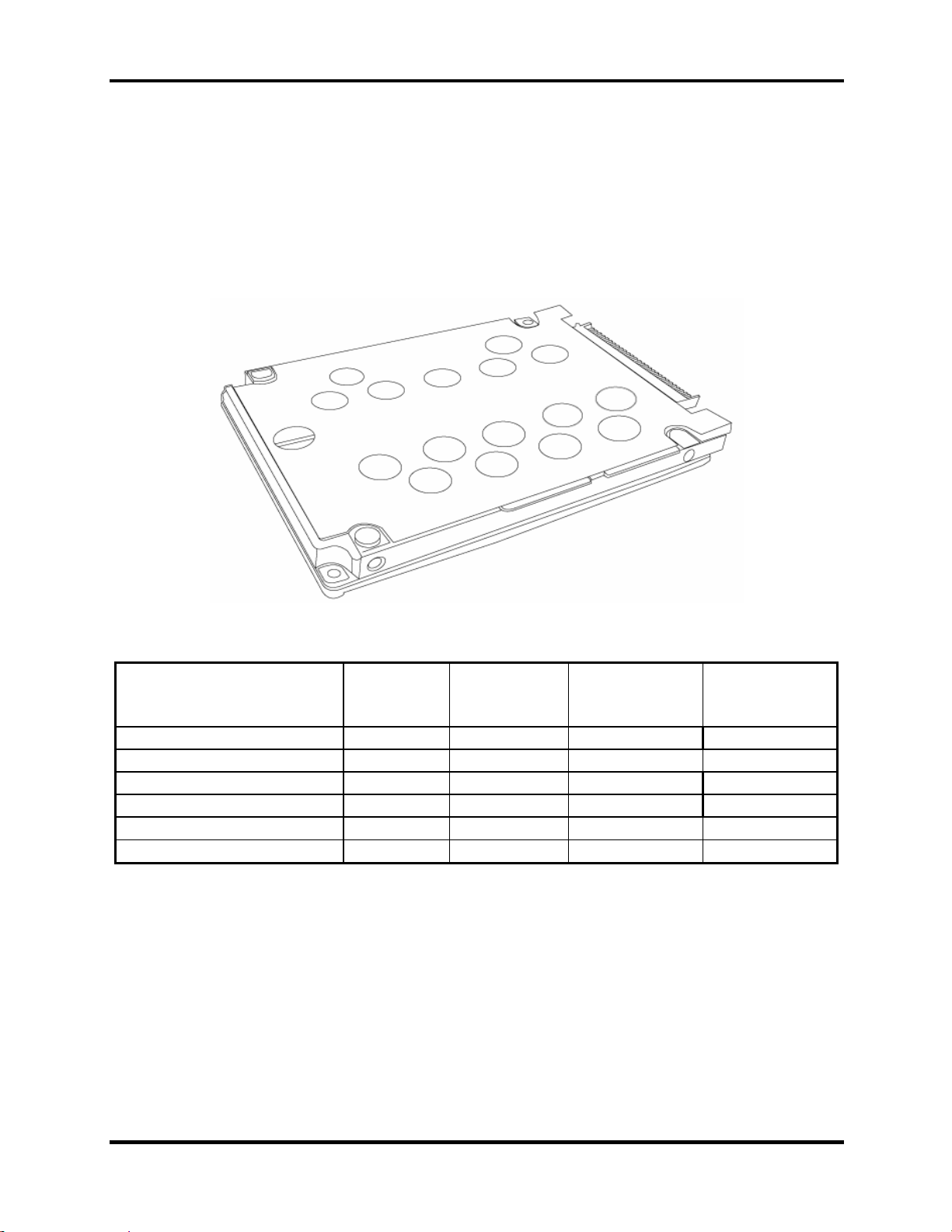
1.3 2.5-inch Hard Disk Drive
The internal HDD is a random access non-volatile storage device. It has a non-removable 2.5inch magnetic disk and mini-Winchester type magnetic heads. The computer supports up
to100GB HDD.
The HDD is shown in Figure 1-1. Specifications are listed in Table 1-1
Figure 1-1 2.5-inch HDD
Items 40GB 60GB 80GB 100GB
Formatted capacity (GB) 37.26 55.89 74.52 93.15
Logical Blocks (LBA) 78,125,000 117,187,500 156,301,488 195,371,568
Rotational speed (rpm) 4,200/5400 4,200/5400 4200/5400 4200/5400
Toshiba HDD Buffer (MB) 8/16 8/16 8/16 8/16
Hitachi HDD Buffer (MB) 2/8 8/8 8/8 NA/8
Bytes per sector 512 512 512 512
Table 1-1 2.5-inch HDD specifications
Satellite A80/A85 Series Maintenance Manual
[CONFIDENTIAL]
1-11
Page 22
1 Hardware Overview 1.4 Optical device Drives
1.4 Optical device Drives
• DVD-ROM & CD-RW drive
• DVD Super Multi drive
1.4.1 DVD-ROM & CD-RW
The DVD Super Multi drive accepts 12-cm (4.72-inch) and 8-cm (3.15-inch) discs. At maximum,
the drive can play back a DVD at 8x speed, read CD-ROM at 24x speed, and write CD-R at 24x
speed and CD-RW at 4x speed or High speed CD-RW at 10X or Ultra speed CD-RW at 24X
speed.
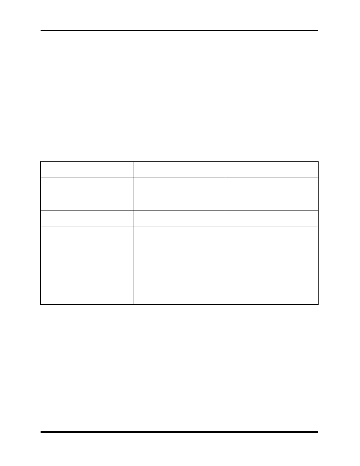
The specifications of the DVD-ROM & CD-RW drive are listed in Table 1-2.
Item DVD-ROM mode CD-ROM mode
Data transfer rate (Mbytes/s)
Access time (ms)
Average random access
33.3 (U-DMA transfer mode 2)
16.6 (PIO mode 4, Multiword DMA mode 2)
180 150
Data buffer size (Mbytes) 2MB
DVD:
DVD-VIDEO, DVD-ROM, DVD-R (3.9G,4.7G), DVD-RW
(Ver.1.1), DVD-RAM, DVD+R, DVD+RW, DVD+R DL.
Formats supported
CD:
CD-DA, CD-ROM, CD-R, CD-RW, CD-ROMXA,
PhotoCD (muitiSession), Video CD, CD-Extra (CD+), CD-Text
Table 1- 2 DVD-ROM & CD-RW drive specifications
1-12
[CONFIDENTIAL]
Satellite A80/A85 Series Maintenance Manual
Page 23
1.4 Optical device Drives 1 Hardware Overview
1.4.2 DVD Super Multi Double Layer
The DVD Super Multi drive accepts 12-cm (4.72-inch) and 8-cm (3.15-inch) discs. At maximum,
the drive can play back a DVD at 8x speed, read CD-ROM at 24x speed, and write CD-R at 24x
speed and CD-RW at 4x speed or Ultra and High speed CD-RW at 10x speed and DVD-R at 8x
speed and DVD-RW at 4x speed and DVD+R at 8x speed and DVD+RW at 4x speed and DVDRAM at 5x speed and DVD+R DL at 2.4x speed.
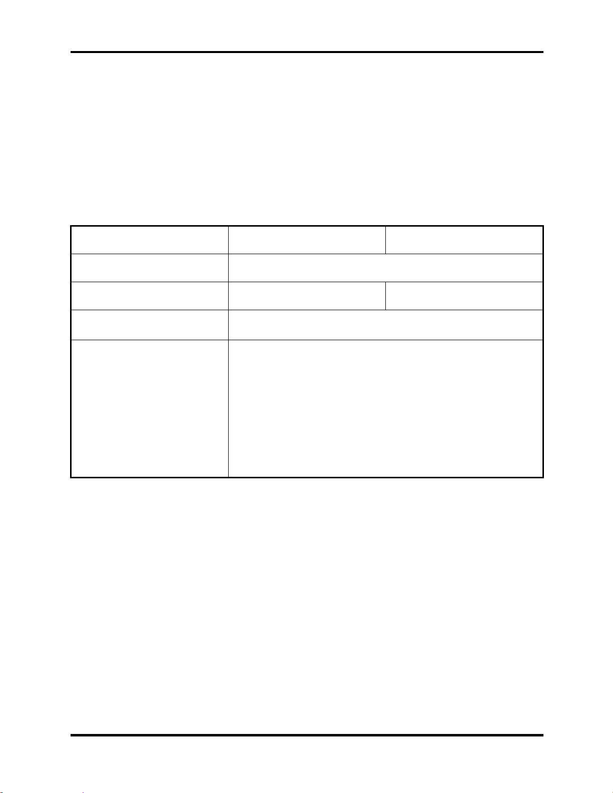
The specifications of the DVD Super Multi Double Layer drive are listed in Table 1-3
Item DVD-ROM mode CD-ROM mode
Data transfer rate (Mbytes/s)
Access time (ms)
Average random access
33.3 (U-DMA transfer mode 2)
16.6 (PIO mode 4, Multiword DMA mode 2)
180 150
Data buffer size (Mbytes) 2MB
DVD:
DVD-VIDEO, DVD-ROM, DVD-R (4.7G), DVD-RW (Ver.1.1),
DVD-RAM, DVD+R, DVD+RW, DVD+R DL.
Formats supported
CD:
CD-DA, CD-ROM, CD-R, CD-RW, CD-ROMXA,
PhotoCD (muitiSession), Video CD, CD-Extra (CD+), CD-Text
Table 1- 3 DVD Super Multi Double Layer drive specifications
Satellite A80/A85 Series Maintenance Manual
[CONFIDENTIAL]
1-13
Page 24

1 Hardware Overview 1.5 Power Supply
1.5 Power Supply
This specification defines the performance and characteristic of 65W and 75W AC adapter power
supply. It supplies a constant voltage 19V output source for A80/A85 series notebook computer.
A/D conversion
• The EC uses 10-bit sampling for A/D conversion to determine the following values:
– AC adaptor current
– Battery and temperature
AC adaptor and battery check
• The EC checks the following by A/D converted values:
– Battery installed
• The EC checks the following by GPIO values:
– AC adaptor connected
Abnormal check
• The EC determines whether the condition is abnormal, and if so, stores an error code
into the error register.
Input port management
• The EC monitors the following input signal status:
– System power ON/OFF status
– Direct CD power ON/OFF status
Beep and LED control
• Beep is caused by the low battery status.
• The EC controls the following two kinds of LED
– DC IN LED (one color: green)
• Green = indicates AC adaptor is connected
– Battery LED (two colors: orange and green)
• Green solid = The battery is fully charged.
• Orange = The computer is quick-charging the battery / The battery is low.
Power ON/OFF sequence
• When power is turned on or off, the EC starts the power on or off sequence.
– SQ0-4 = power ON sequence
– SQ5-B = power OFF sequence
1-14
[CONFIDENTIAL]
Satellite A80/A85 Series Maintenance Manual
Page 25

1.5 Power Supply 1 Hardware Overview
Battery charging control
• The EC controls the following.
– The quick charging ON/OFF
– The detection of full charge
Detection of the low battery
• The EC detects the low battery point by the gas gauge.
– LB10M = The system will be driven by the battery for 12 more minutes.
– LB0 = The battery won't be able to drive the system after 3 minutes.
– LB1 = The battery can drive the system only during the suspend process.
– LB2 = The battery cannot drive the system.
New battery installation
• When a new battery is installed, the EC communicates with the E2PROM in the
battery to read information of the newly installed battery.
Battery capacity calculation
• The EC reads battery remaining and percentage capacity from the battery through
SMBus.
Satellite A80/A85 Series Maintenance Manual
[CONFIDENTIAL]
1-15
Page 26

1 Hardware Overview 1.6 Batteries
1.6 Batteries
The computer has two types of battery:
Main battery pack (18650 size)
RTC battery
The removable main battery pack is the computer’s main power source when the AC adaptor is
not attached.
The battery specifications are listed in the table below.
Battery name Material Output voltage Capacity
Main battery (4 cell) Lithium-Ion 14.4 V 2000mAH
Main battery (8 cell) Lithium-Ion 14.4 V 4300mAH
RTC battery Lithium 3.3 V 15 mAh
1-16
[CONFIDENTIAL]
Satellite A80/A85 Series Maintenance Manual
Page 27
1.6 Batteries 1 Hardware Overview
1.6.1 Main Battery
Battery charging is controlled by a power supply microprocessor that is mounted on the system
board. The power supply microprocessor controls whether the charge is on or off and detects a
full charge when the AC adaptor and battery are attached to the computer. The system charges
the battery using quick charge or trickle charge.
Quick Battery Charge
When the AC adaptor is attached, there are two types of quick charge: quick charge when
the system is powered off and normal charge when the system is powered on.
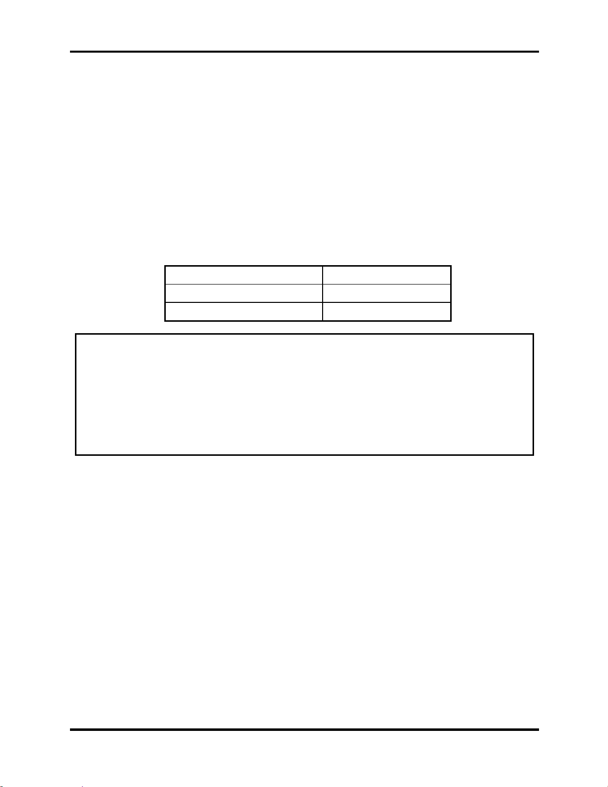
The times required for charges are listed in the table below.
Status Charging time
Normal charge (power on) 12 hours or longer
Quick charge (power off) About 4 hours or longer
NOTES
1. The time required for normal charge is affected by the amount of power the system
is consuming. Use of the fluorescent lamp and frequent disk access diverts power
and lengthens the charge time.
2. Using quick charge, the power supply microprocessor automatically stops the
charge after eight hours regardless of the condition of the battery. Overcharging
could cause the battery to explode.
If any of the following occurs, the battery quick charge process stops.
1. The battery becomes fully charged.
2. The AC adaptor or battery is removed.
3. The battery or output voltage is abnormal.
4. The battery temperature is abnormal.
5. The battery SMBus communication fails.
6. The battery cell is bad.
Detection of full charge
A full charge is detected from the battery pack through SMBus when the battery is
charging.
Satellite A80/A85 Series Maintenance Manual
[CONFIDENTIAL]
1-17
Page 28
1 Hardware Overview 1.6 Batteries
1.6.2 RTC battery
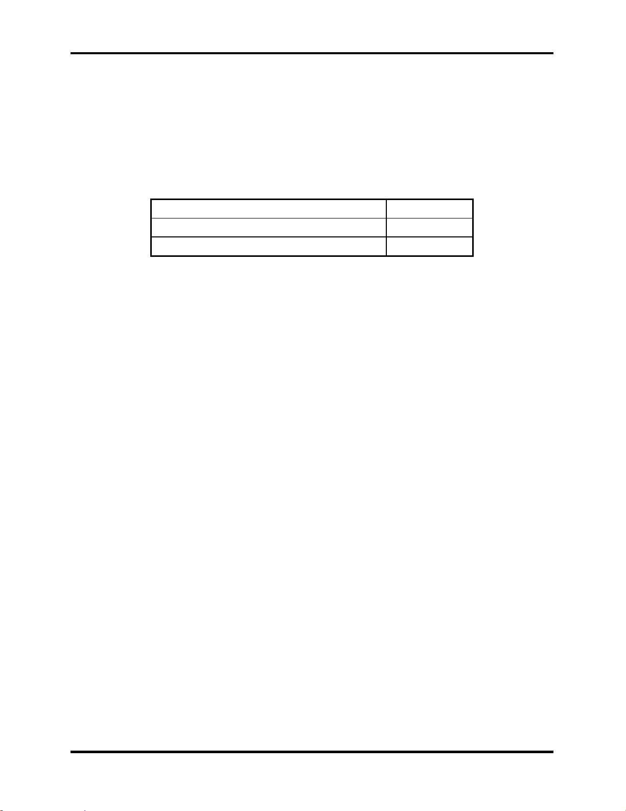
The RTC battery provides power to keep the current date, time and other setup information in
memory while the computer is turned off. The table below lists the charging time and data
preservation period of the RTC battery. The RTC battery is charged by the adaptor or main
battery, while the computer is powered on.
Status Time
Charging Time (power on) About 24 hours
Data preservation period (full charge) 1 month
1-18
[CONFIDENTIAL]
Satellite A80/A85 Series Maintenance Manual
Page 29

Chapter 3
Tests and Diagnostics
3
[CONFIDENTIAL]
Page 30

Contents
3.1 The Diagnostic Test .........................................................................................................3-3
3.2 Executing the Diagnostic Test..........................................................................................3-4
3.3 Config Check Test............................................................................................................3-8
3.4 DMI Check Test...............................................................................................................3-9
3.5 Speaker Audio Test........................................................................................................3-10
3.6 Fan ON/OFF Test...........................................................................................................3-12
3.7 Main Battery Charge Test ..............................................................................................3-13
3.8 FDD Test........................................................................................................................3-14
3.9 CD-ROM Test................................................................................................................3-15
3.10 Keyboard Test ................................................................................................................3-16
3.11 Mouse (Pad) Test ...........................................................................................................3-19
3.12 LCD Pixels Mode Test...................................................................................................3-21
3.13 Lid Switch Test ..............................................................................................................3-22
3.14 HDD R/W Test...............................................................................................................3-23
3.15 LAN Test........................................................................................................................3-25
RTC Test ........................................................................................................................3-27 3.16
3.17 CD Control Button Test .................................................................................................3-28
3-2
Manual
[CONFIDENTIAL]
Satellite A80/A85Series Maintenance
Page 31

The Diagnostic Test
This chapter explains how to use the Test & Diagnostic program to test the functions of the
(Base on Sakhir10E T&D version 1.0) hardware modules. The Test & Diagnostic Program is
stored on the T&D diskettes. The program consists of a series of tests that run automatically
w xecuted.
hen the Diagnostics Program items are selected and e
NOTES: To start the diagnostics, follow thes
e steps
1. Check all cables for loose connections.
2. Exit this program when you are at Main Menu.
The TEST & DIAGNOSTIC PROGRAM contains the following functional tests:
CONFIG CHECK TEST
DMI CHECK TEST
SPEAKER AUDIO TEST
FAN ON/OF
MAIN BATTERY
F TEST
CHARGE TEST
FDD TEST
CD-ROM TEST
KEYBOARD TEST
MOUSE(PAD) TEST
LCD PIXELS MO
MAGNETIC
HDD R/W T
DE TEST
SWITCH TEST
EST
LAN TEST
RTC TEST
Button Test
You
will need the following equipment to perform some of the Diagnostic test programs.
The diagnostics diskette (2 pcs)
A formatted working diskette for the flop
py disk drive test (Floppy Disk Drive Test)
A data CD disc (CD-ROM Test)
A LAN loopback connector (LAN Test)
he following sections explain how to execute the Test & Diagnostic Program and detail the
T
tests within the program.
Satellite A80/A85 Series Maintenance Manual
[CONFIDENTIAL]
3-3
Page 32

3. Tests and Diagnostics 3.2 Executing the Diagnostic Test
3.1 Executing the Diagnostic Test
Toshiba MS-DOS is required to run the DIAGNOSTICS PROGRAM. To start the
DIAGNOSTIC PROGRAM, follow these steps:
1. Insert the diagnostics diskette #1 in the floppy disk drive and turn on the computer. (The
diagnostics diskette contains the MS-DOS boot files.) And then follow the instructions to
swap with the diagnostics diskette #2 for T&D program installed in RAM driver.
NOTE: To execute the CD test, make sure the CD is installed in the ODD drive.
The T&D Program can run by single test item when you press corresponsive English
letter of test item, or run two or more test items what you like if you choose them by
“Arrow cursors” and “Space Bar” – the wonderful thing is you can setup test loop by
“Enter” button. And it also asks you if you like to copy test log file to diskette as
reference at the end of test(s).
The test list is as the following:
A. CONFIG CHECK TEST
B. DMI CHECK TEST
C. RTC TEST
D. LAN TEST
E. SPEAKER AUDIO TEST
F. FAN ON/OFF TEST
G. MAIN BATTERY CHARGE TEST
H. FDD TEST
I. CD-ROM TEST
J. KEYBOARD TEST
K. MOUSE (PAD) TEST
L. LCD PIXELS MODE TEST
M. MAGNETIC SWITCH TEST
N. HDD R/W TEST
O: Button test
3-4
Manual
[CONFIDENTIAL]
Satellite A80/A85Series Maintenance
Page 33

3.2 Executing the Diagnostic Test 3. Tests and Diagnostics
The below display will show up at the beginning of T&D program
If the test result passes, the following display will show up:
Satellite A80/A85 Series Maintenance Manual
[CONFIDENTIAL]
3-5
Page 34

3. Tests and Diagnostics 3.2 Executing the Diagnostic Test
If an error is detected and a test fails, the following message displays:
Then press any key for next actions – the below display presented if copying test log file
onto diskette is necessary. This action will be executed when “Y” key pressed.
3-6
Manual
[CONFIDENTIAL]
Satellite A80/A85Series Maintenance
Page 35

3.2 Executing the Diagnostic Test 3. Tests and Diagnostics
It will skip this process if “N” key pressed.
And then it will check if it’s necessary to leave this program. Program will quit when “Y”
key pressed and it will go back main menu for next test if “N” key pressed.
NOTE: Press Pause to pause a test and Enter to resume.
Satellite A80/A85 Series Maintenance Manual
[CONFIDENTIAL]
3-7
Page 36

3. Tests and Diagnostics 3.7 Speaker Audio Test
3.2 Config Check Test
The config check test checks unit configuration. It includes:
CPU type (P4/CEL; Dothan; Cache ; CPU speed )
BIOS version
Panel ID
VRAM size
System memory size (*** MB)
ODD type (DVD-SuperMulti; COMBO; …)
HDD type & capacity (Vendor ID. Model .Firmwave)
Wireless type
LAN Type (LAN10/100; GigaLAN)
With/Without Bluetooth (BLUE/NONE)
FIR
Battery cell
This test needs input unit Part Number by manual to make comparison with known SKU data.
NOTE: To execute this test, you must input unit Part Number as “Uppercase Character”.
Then it will show its configuration is correct (in green color) or failed (in red color).
The screen should display as below, indicating whether the test is passed or failed after
comparison.
3-8
Manual
[CONFIDENTIAL]
Satellite A80/A85Series Maintenance
Page 37

3.7 Speaker Audio Test 3. Tests and Diagnostics
3.3 DMI Check Test
This test will check if the computer’s Desktop Management Interface (DMI) is correct.
DMI includes:
Manufacturer
Production Name
Version
Serial Number
UUID
OEM String
It needs to input unit Part Number by manual, then show this unit DMI information and makes
comparison with SKU data.
NOTE: To execute this test, you must input unit Part Number as “Uppercase Character”.
Satellite A80/A85 Series Maintenance Manual
[CONFIDENTIAL]
3-9
Page 38

3. Tests and Diagnostics 3.7 Speaker Audio Test
The screen should display as below, indicating whether the test is passed or failed after
comparison.
3.4 speaker Audio Test
The speaker audio test allows the user to aurally confirm the speaker functions. And check both
speakers if they are OK within 3 times “Beep” sound generated.
NOTE: Remember to tune up the volume as “Maximum” before this test starts.
The screen should display as below, indicating whether the test is passed or failed after the
question.
3-10
Manual
[CONFIDENTIAL]
Satellite A80/A85Series Maintenance
Page 39

3.7 Speaker Audio Test 3. Tests and Diagnostics
Satellite A80/A85 Series Maintenance Manual
[CONFIDENTIAL]
3-11
Page 40

3. Tests and Diagnostics 3.8 Fan ON/OFF Test
3.5 Fan ON/OFF Test
The fan test allows the user to test aurally whether the fan is working. And follow the below
procedures for this test:
The computer will let the fan be “ON” after any key pressed. Listen to check
whether the fan is working.
NOTE: Remember to approach fan outlet that is near right side of unit whether fan is
“ON”.
The computer will stop the fan working after any key pressed. Listen to check if
the fan is “OFF” – it means no rotating sound.
The screen should display as below, indicating whether the test is passed or failed after the
question.
3-12
Manual
[CONFIDENTIAL]
Satellite A80/A85Series Maintenance
Page 41

3.9 Main Battery Change Test 3. Tests and Diagnostics
3.6 Main Battery Charge Test
NOTE: The AC adaptor (75W, 19V) should be connected to successfully run this test.
This test shows and measures the main battery:
Battery type (Lion)
Manufacturer (Sanyo/Panasonic)
Remain charge capacity (0 ~ 100%)
Charge function (PASS/FAIL)
- “Battery Is Full” showed when “remain charge capacity” is 100%
The screen should display as below, indicating whether the test is passed or failed when finished.
Satellite A80/A85 Series Maintenance Manual
[CONFIDENTIAL]
3-13
Page 42

3 Tests and Diagnostics 3.10 FDD Test
3.7 FDD Test
NOTE: Before running the FDD test, prepare a formatted work diskette (1.44 MB).
Remove the diagnostics diskette and insert the work diskette into the FDD. The contents of
the floppy diskette maybe erased.
The Floppy Disk Test includes three subtests of the:
1. Sequential seek/verify function (Range: Track 0 ~ 79)
2. Funnel code seek/verify function (Range: Track 0 ~ 79)
3. Write/Read/Compare pattern function (Range: Track 75 ~ 79)
NOTE: The write-protected device of this formatted diskette should be “Disable”.
The subtests run automatically.
NOTE: Press “Esc” key can skip the current subtest.
The screen should display as below, indicating whether the subtests pass or fail when finished.
3-14
Manual
[CONFIDENTIAL]
Satellite A80/A85Series Maintenance
Page 43

3.11 CD-ROM Test 3 Tests and Diagnostics
3.8 ODD Test
The ODD test allows a user to aurally confirm the CD-ROM functions.
NOTE: A CD disc (including data file) must be inserted into the ODD drive before this test
starts.
The CD-ROM test includes two subtests of the:
1. Random read/partial sequential read function
2. Sequential read function (for all surface)
Each item can be chosen by manual. When each test item finished, the CD-ROM tray will open.
Check whether the tray can open automatically.
NOTE: Press “Esc” key can skip the current subtest.
The screen should display as below, indicating whether the subtests pass or fail when finished.
Satellite A80/A85 Series Maintenance Manual
[CONFIDENTIAL]
3-15
Page 44

3. Tests and Diagnostics 3.12 Keyboard Test
3.9 Keyboard Test
The keyboard test checks the all keys function.
NOTE: The Num Lock and the Overlay mode must be off to execute the keyboard test.
Before keyboard test starts, the keyboard matrix code should be chosen as below display:
1. K (UK, for Europe)
2. S (US, for America)
3. J (JP, for Japan)
When you execute this test, the keyboard layout is drawn on the display. When any key is
pressed, the corresponding key on the screen changes to black as shown below.
It will indicate whether the subtest is passed or failed after the question.
NOTE: The “Fn” key cannot be tested in the keyboard test. To determine whether the “Fn”
key is working correctly, press “Fn+F6 ” or “Fn+F7 ” keys to check if LCD display
brightness change gradually.
3-16
Manual
[CONFIDENTIAL]
Satellite A80/A85Series Maintenance
Page 45

3.12 Keyboard Test 3. Tests and Diagnostics
Satellite A80/A85 Series Maintenance Manual
[CONFIDENTIAL]
3-17
Page 46

3. Tests and Diagnostics 3.12 Keyboard Test
p
9
Pressing a key also reveals that key’s scan codes in the upper right hand corner of the screen.
When the key is depressed, its make code is displayed. When the key is released, the break code
is shown.
3-18
Manual
[CONFIDENTIAL]
Satellite A80/A85Series Maintenance
Page 47

3.13 Mouse (Pad) Test 3. Tests and Diagnostics
3.10 Mouse (Pad) Test
The Mouse test allows the user to select and assign values to the following, using the Touch Pad
or “Tab” key to move between selections:
1. Mouse Speed (on a scale from slow to fast)
2. Acceleration (Off, Low, Medium, High)
3. Button Assignments (Left + Right / Right button, either Unassigned or Drag
Lock)
4. Swap Buttons (Left /Right)
NOTE: The Touch Pad test cannot be used to test an external USB mouse.
The Touch Pad button subtest allows users to test their Touch Pad buttons. If the buttons are
clicked, the cursors should appear in the corresponding box of the button figure that is displayed
on the screen as below.
Satellite A80/A85 Series Maintenance Manual
[CONFIDENTIAL]
3-19
Page 48

3. Tests and Diagnostics 3.13 Mouse (Pad) Test
After checking T/Pad buttons and cursor’s function, use “Tab” key or use T/Pad cursor to click
the “OK” column will end this test.
It will indicate whether the subtests pass or fail after three questions.
NOTE: The above figure has three compartments although the Touch Pad installed may
only have two buttons. In this case, the central compartment in the figure does not
correspond to any button.
3-20
Manual
[CONFIDENTIAL]
Satellite A80/A85Series Maintenance
Page 49

3.14 LCD Pixels Mode Test 3. Tests and Diagnostics
3.11 LCD Pixels Mode Test
This LCD pixels mode test checks whether video display is fine.
This test includes two modes of the test:
1. Text Mode
- including 40*25 (16 colors) and 80*25 (2/16colors).
2. VGA Mode
- including 320*200 (4/16/256 colors), 640*200 (2/16 colors), 640*350 (2/16 colors),
640*480 (2/16/256 colors), 800*600 (256 colors) and 1024*768 (256 colors).
The screen should display as below, indicating whether the test is passed or failed after the
question.
Satellite A80/A85 Series Maintenance Manual
[CONFIDENTIAL]
3-21
Page 50

3. Tests and Diagnostics 3.15 Lid Switch Test
3.12 Magnetic Lid Switch Test
The lid switch test checks the lid function of the unit. When LCD cover closed, the lid should
enable to turn off the display.
NOTE: Remember to tune up the volume as “Maximum” before this test starts.
Follow below steps to run this test:
1. Close the LCD cover.
2. Heard 3 “Beep” sound happened during LCD closed.
3. Open the LCD.
Then it will indicate whether the test is passed or failed.
3-22
Manual
[CONFIDENTIAL]
Satellite A80/A85Series Maintenance
Page 51

3.16 HDD R/W Test 3. Tests and Diagnostics
3.13 HDD R/W Test
The HDD R/W test allows the user to test aurally HDD read/write function. For data security
concern, it is necessary to input password - “hard disk” before HDD write test starts.
The HDD test includes three subtests of the:
1. Sequential read (all surface)
2. Sequential write (all surface)
3. Partial W/R + Random W/R
After the choice is made, HDD information will show as below:
Model name
Firmware revision
Serial number
CHR (Cylinder High Register) mode – including cylinders, heads, sectors and sizes.
LBA (Logical Block Addressing) mode – including sectors and sizes.
Support Ultra DMA Mode
Satellite A80/A85 Series Maintenance Manual
[CONFIDENTIAL]
3-23
Page 52

3. Tests and Diagnostics 3.16 HDD R/W Test
NOTE: Press “Ctrl + Break” keys can terminate the current subtest.
The screen should display as previous picture, indicating whether the subtest is passed or failed
when finished.
NOTE: The AC adaptor should be connected to successfully run this test.
3-24
Manual
[CONFIDENTIAL]
Satellite A80/A85Series Maintenance
Page 53

3.17 LAN Test 3. Tests and Diagnostics
3.14 LAN Test
The LAN test checks the LAN full-duplex environment.
NOTE: LAN loopback needs to plug in before test begins.
And LAN information will show on the test screen:
IO Base – Port: 3000H
IRQ – AH, it’s “IRQ 10”.
Node – it is “MAC Address”.
Line Frame – 1514 Bytes.
Line Speed – 100Mbps or 10 Mbps.
Bus ID – it’s “4”.
The LAN test includes two subtests of the:
1. Speed100
- including Ethernet_802.2, Ethernet_II, Ethernet_SNAP and Ethernet_802.3. All
test items are in LSB mode.
2. Speed10
- including Ethernet_802.2 in LSB mode.
The subtests run automatically.
Satellite A80/A85 Series Maintenance Manual
[CONFIDENTIAL]
3-25
Page 54

3. Tests and Diagnostics 3.17 LAN Test
The screen should display as below, indicating whether the subtests pass or fail when finished.
If an error is detected and a test fails, the following message displays:
3-26
Manual
[CONFIDENTIAL]
Satellite A80/A85Series Maintenance
Page 55

3.18 RTC Test 3. Tests and Diagnostics
3.15 RTC Test
Checks the computer’s RTC (Real Time Clock) and calendar functions by comparing the DOS
and CMOS values.
The test runs automatically.
The screen should display as below, indicating whether the test is passed or failed when finished.
Satellite A80/A85 Series Maintenance Manual
[CONFIDENTIAL]
3-27
Page 56

3. Tests and Diagnostics 3.19 CD Control Button Test
3.16 CD Control Button Test
The CD control button test allows the user to manually test each of the five CD control buttons.
Key ”WWW” need to press first. One will hear one “bi” sound when press ”WWW” or “Audio”
Sound, and continuously “bi” sound for another key test.
The figure below will be displayed:
Press each of the buttons on the front panel in turn. A yellow bar will appear on the
relevant section of the figure if the button passes the test.
Press Ctrl +C to quit the test.
3-28
Manual
[CONFIDENTIAL]
Satellite A80/A85Series Maintenance
Page 57

Chapter 4
Replacement Procedures
4
[CONFIDENTIAL]
Page 58

4 Replacement Procedures
4-ii
[CONFIDENTIAL]
Satellite A80 /A85 Series Maintenance Manual
Page 59

4 Replacement Procedures
Chapter 4 Contents
4.1 General.............................................................................................................................4-1
4.2 Battery.............................................................................................................................. 4-7
4.3 PC Card............................................................................................................................4-9
4.4 HDD...............................................................................................................................4-11
4.5 Optical Drive Module.................................................................................................... 4-14
4.6 Optical Drive..................................................................................................................4-15
4.7 Wireless LAN ................................................................................................................4-16
4.8 Modem........................................................................................................................... 4-18
4.9 Expansion Memory Module .......................................................................................... 4-19
4.10 Keyboard........................................................................................................................4-23
4.11 Display Assembly..........................................................................................................4-26
4.12 Top Cover ......................................................................................................................4-28
4.13 Direct Play Button Board...............................................................................................4-31
4.14 Memory Module ............................................................................................................4-32
4.15 Touch Pad ......................................................................................................................4-33
4.16 Speakers......................................................................................................................... 4-34
4.17 System Board.................................................................................................................4-35
4.18 Heat Sink, & CPU..........................................................................................................4-40
4.19 Display Mask................................................................................................................. 4-42
4.20 LCD Module.................................................................................................................. 4-43
4.21 FL Inverter Board ..........................................................................................................4-45
Satellite A80 /A85 Series Maintenance Manual
[CONFIDENTIAL]
4-iii
Page 60

4 Replacement Procedures
Figures
Figure 4-1 Removing the battery pack ...................................................................................4-7
Figure 4-2 Removing a PC Card.............................................................................................4-9
Figure 4-3 Installing a PC Card............................................................................................4-10
Figure 4-4 HDD....................................................................................................................4-11
Figure 4-5 Removing the HDD door....................................................................................4-11
Figure 4-6 Removing the HDD module ...............................................................................4-12
Figure 4-7 Removing the HDD bracket................................................................................4-13
Figure 4-8 Removing the optical drive module....................................................................4-14
Figure 4-9 Removing the optical drive bracket ....................................................................4-15
Figure 4-10 Removing the wireless LAN cover.....................................................................4-16
Figure 4-11 Removing the wireless LAN unit........................................................................4-17
Figure 4-12 Removing the modem module ............................................................................4-18
Figure 4-13 Removing the memory module cover.................................................................4-19
Figure 4-14 Removing a memory module..............................................................................4-20
Figure 4-15 Removing an expansion memory cover..............................................................4-21
Figure 4-16 Installing an expansion memory .........................................................................4-22
Figure 4-17 Removing the strip cover....................................................................................4-23
Figure 4-18 Removing the keyboard ......................................................................................4-24
Figure 4-19 Disconnecting the keyboard cable ......................................................................4-25
Figure 4-20 Removing the display assembly screws..............................................................4-26
Figure 4-21 Removing the wireless and LCD cables .............................................................4-27
Figure 4-22 Removing screws of the bottom..........................................................................4-28
Figure 4-23 Removing the top cover .....................................................................................4-29
Figure 4-24 Removing FFC cable ..........................................................................................4-29
Figure 4-25 Removing Speaker cables ...................................................................................4-30
4-iv
[CONFIDENTIAL]
Satellite A80 /A85 Series Maintenance Manual
Page 61

4 Replacement Procedures
Figure 4-26 Removing the Direct Play Button board ............................................................ 4-31
Figure 4-27 Removing the Memory Module .........................................................................4-32
Figure 4-28 Removing the Touch Pad board .........................................................................4-33
Figure 4-29 Removing the speakers.......................................................................................4-34
Figure 4-30 Removing LAN board ........................................................................................ 4-35
Figure 4-31 Removing the fan module................................................................................... 4-36
Figure 4-32 Removing USB board........................................................................................4-37
Figure 4-33 Removing the system board ...............................................................................4-38
Figure 4-34 Removing the heat sink ......................................................................................4-40
Figure 4-35 Removing the CPU.............................................................................................4-41
Figure 4-36 Removing the display mask................................................................................4-42
Figure 4-37 Removing the LCD module-1 ............................................................................4-43
Figure 4-38 Removing the LCD module-2 ............................................................................4-44
Figure 4-39 Removing the FL inverter board ........................................................................4-45
Satellite A80 /A85 Series Maintenance Manual
[CONFIDENTIAL]
4-v
Page 62

4 Replacement Procedures
4.1 General
This chapter explains how to disassemble the computer and replace Field Replaceable Units
(FRUs). It may not be necessary to remove all the FRUs in order to replace one. The chart below
is a guide to which FRUs need to be removed in order to remove others. Always start by
removing the battery pack, next, optional items such as the optional PC Card, then follow the
chart downward removing only those FRUs necessary to reach the one you think is causing the
computer to operate improperly. Refer to the example on the following page.
Battery pack
Wireless LAN
HDD ODD Modem Keyboard
Expansion Memory
Module
Display Assembly
Top Cover Display Mask
System Board LCD Module
Fan & Heat Sink
CPU
Speakers
Memory
Module
Touch Pad
Direct Play
Button Board
FL Inverter
Board
Satellite A80 /A85 Series Maintenance Manual
[CONFIDENTIAL]
4-1
Page 63

4 Replacement Procedures
The example below shows FRUs to be removed before the CPU can be removed and repaired or
replaced. The CPU is overlapped by the top cover which must be removed before the CPU can
be reached. The removable HDD, keyboard, wireless LAN, ODD, modem, and display assembly
in turn overlap the top cover. Always starts the disassembly process by removing the battery
pack.
Battery pack
Wireless LAN
Expansion Memory
Module
System Board LCD Module
Fan & Heat Sink
CPU
HDD
ODD Modem
Top Cover Display Mask
Speakers
Memory
Module
Keyboard
Touch Pad
Display Assembly
Direct Play
Button Board
FL Inverter
Board
4-2
[CONFIDENTIAL]
Satellite A80 /A85 Series Maintenance Manual
Page 64

4 Replacement Procedures
Safety Precautions
Before you begin disassembly, read the following safety precautions and observe them carefully
as you work.
DANGER:
1. Always use the lithium ion battery pack or backup battery that is authorized by
Toshiba or compatible with the unit. Since other battery packs have different
specifications, they may be incompatible with the unit, and may burst or explode.
Heating or disassembling the battery pack could cause leakage of alkaline solution.
Throwing the battery pack into a fire could cause the battery pack to explode.
2. The power supply, FL inverter and other components carry high voltages. To avoid
the risk of electric shock when you need to turn on the power of a partially
disassembled computer to check its operation, be very careful not to touch
connectors or components. Also, do not disassemble individual components in firstlevel maintenance.
WARNING: To avoid the risk of electric shock or other injury:
1. Always turn the power off and disconnect the AC adaptor from the power source.
2. Remove any metal jewelry or accessories such as necklaces, bracelets, or rings.
Batteries in the computer retain an electrical charge so there is danger of electrical
shock even when the computer is disconnected from an AC power source.
3. Never work with wet or damp hands.
4. The computer contains sharp edges and corners: be careful not to injure yourself.
5. Make sure that all replacement components meet the specifications for the computer
and that all cables and connectors are securely fastened.
CAUTION: To avoid damage to the computer:
1. When you change a component, be sure the replacement component meets the required
specifications. Never use foreign parts.
2. Metal objects such as screws or paper clips which fall into the unit can cause a shortcircuit, fire, or other internal damage.
3. When assembling the computer, make sure you use the correct screws to secure the
various pieces in place. Screw sizes are listed in their corresponding figure. Make sure
all screws are securely fastened. Loose screws can cause short circuits, resulting in
heat, smoke, or fire.
4. Before removing an FRU or other component, make sure all cables to the component
have been disconnected.
5. If you use AC power, be sure to use the cable that came with the computer or one
recommended by Toshiba.
Satellite A80 /A85 Series Maintenance Manual
[CONFIDENTIAL]
4-3
Page 65

4 Replacement Procedures
Before You Begin
Look over the procedures in this section before you begin disassembling the computer.
Familiarize yourself with the disassembly and reassembly steps. Begin each procedure by
removing the AC adaptor and the battery pack as instructed in section 4.2.
1. Do not disassemble the computer unless it is operating abnormally.
2. Use only the correct and approved tools.
3. Make sure the working environment is free from the following elements whether you are
using or storing the computer.
Dust and contaminates
Static electricity
Extreme heat, cold and humidity
4. Make sure the FRU you are replacing is causing the abnormal operation by performing the
necessary troubleshooting and diagnostics tests described in chapters 2 and 3 of this manual.
5. Do not perform any operations that are not necessary and use only the described procedures
for disassembling and installing FRUs in the computer.
6. After removing parts from the computer, place them in a safe place away from the computer
so they will not be damaged and will not interfere with your work.
7. You will remove and replace many screws when you disassemble the computer. When you
remove screws, make sure they are placed in a safe place and identified with the correct
parts.
8. When assembling the computer make sure you use the correct screws to secure the various
pieces. Screw sizes are listed in their corresponding figures.
9. The computer contains many sharp edges and corners, so be careful not to injure yourself.
10. After you have replaced an FRU, make sure the computer is functioning properly by
performing the appropriate test on the FRU you have fixed or replaced.
4-4
[CONFIDENTIAL]
Satellite A80 /A85 Series Maintenance Manual
Page 66

4 Replacement Procedures
Disassembly Procedures
The computer has two basic types of cable connectors:
Pressure Plate Connectors
Standard Pin Connectors
To disconnect a Pressure Plate connector, lift up the tabs on either side of the connector’s plastic
pressure plate and slide the cable out of the connector. To connect the cable to a Pressure Plate
connector, make sure the pressure plate is fully lifted and slide the cable into the connector.
Secure the cable in place by pushing the sides of the pressure plate down so the plate is flush
with the sides of the connector. Gently pull on the cable to make sure the cable is secure. If you
pull out the connector, connect it again making sure the connector’s pressure plate is fully lifted
when you insert the cable.
Standard pin connectors are used with all other cables. These connectors can be connected and
disconnected by simply pulling them apart or pushing them together.
Assembly Procedures
After you have disassembled the computer and fixed or repaired the problem that was causing the
computer to operate abnormally, you will need to reassemble the computer.
Install all the removed FRUs following the steps described in the corresponding sections in this
chapter.
While assembling the computer, remember the following general points:
Take your time, making sure you follow the instructions closely. Most problems arise
when you get in a hurry assembling the computer.
Make sure all cables and connectors are securely fastened.
Before securing the FRU or other parts, make sure that no cables will be pinched by
screws or the FRU.
Check that all latches are closed securely.
Make sure all the correct screws are used to secure all FRUs. Using the wrong screw
can either damage the threads on the screw or the head of the screw and may prevent
proper seating of an FRU.
After installing an FRU in the computer, confirm that the FRU and the computer are functioning
properly.
Satellite A80 /A85 Series Maintenance Manual
[CONFIDENTIAL]
4-5
Page 67

4 Replacement Procedures
Tools and Equipment
The use of Electrostatic Discharge (ESD) equipment is very important for your safety and the
safety of those around you. Proper use of these devices will increase the success rate of your
repairs and lower the cost for damaged or destroyed parts. The following equipment is necessary
to disassemble and reassemble the computer:
One M2 Phillips screwdriver to remove and replace screws.
One T5 security screwdriver.
Tweezers, to lift out screws that you cannot grasp with your fingers.
ESD mats for the floor and the table you are working on.
ESD wrist strap or heel grounder.
Anti-static carpeting or flooring.
Air-ionizers in highly static sensitive areas.
4-6
[CONFIDENTIAL]
Satellite A80 /A85 Series Maintenance Manual
Page 68

4 Replacement Procedures
4.2 Battery
Removing the Battery Pack
To remove the battery pack from the battery bay, follow the steps below.
1. Turn the computer upside down.
2. Disengage the battery pack lock (1).
3. Release the battery pack release latch (2).
4. Remove the battery pack from the bay (3).
Figure 4-1 Removing the battery pack
NOTE: For environmental reasons, do not throw away a spent battery pack. Please return
spent battery packs to Toshiba.
Satellite A80 /A85 Series Maintenance Manual
[CONFIDENTIAL]
4-7
Page 69

4 Replacement Procedures
Installing the Battery Pack
To install the battery pack in the battery bay, follow the steps below and refer to the figure in the
preceding section.
WARNING: The battery is a lithium ion battery and can explode if not properly replaced,
used, handled or disposed of. Use only batteries recommended by Toshiba as replacements.
1. Slide the battery pack into the battery bay. The battery bay latch will click automatically.
2. Lock the battery pack lock and battery pack release latch to secure the installation.
4-8
[CONFIDENTIAL]
Satellite A80 /A85 Series Maintenance Manual
Page 70

4 Replacement Procedures
4.3 PC Card
Removing a PC Card
To remove a PC Card, follow the steps below.
1. Push the PC Card’s eject button. The button pops out when you release it.
2. Push the eject button once more to pop the PC Card out slightly.
3. Grasp the PC Card and remove it.
4. Push the eject button back into place, if necessary.
Eject button
Figure 4-2 Removing a PC Card
Satellite A80 /A85 Series Maintenance Manual
[CONFIDENTIAL]
4-9
Page 71

4 Replacement Procedures
Installing a PC Card
To install a PC Card, follow the steps below and refer to the figures in the preceding section.
1. Make sure the eject button does not stick out.
2. Insert a PC Card and press gently to ensure a firm connection.
Figure 4-3 Installing a PC Card
4-10
[CONFIDENTIAL]
Satellite A80 /A85 Series Maintenance Manual
Page 72

4 Replacement Procedures
4.4 HDD
NOTE: When handling the HDD, do not press the top
surface as shown by the arrow. Hold it by the sides.
Figure 4-4 HDD
Removing the HDD Module
Follow the steps below to remove HDD module:
1. Turn the computer upside down
2. Remove two black M2.5x5 screws to release the HDD door.
Satellite A80 /A85 Series Maintenance Manual
[CONFIDENTIAL]
4-11
Page 73

4 Replacement Procedures
Figure 4-5 Removing the HDD door
3. Pull on the tab to remove the HDD unit.
Figure 4-6 Removing the HDD module
4. Remove the HDD from the HDD case.
Installing the HDD Module
To install the HDD module, follow the steps below and refer to the figures in the preceding
section.
1. Insert the HDD module into the HDD case.
2. Secure the HDD door with two black M2.5x5 screws.
4-12
[CONFIDENTIAL]
Satellite A80 /A85 Series Maintenance Manual
Page 74

4 Replacement Procedures
Disassembling the HDD Module
To take apart the HDD module, first remove it from the computer as described earlier.
1. Remove four M3x3 screws securing the HDD mounting brackets to the HDD. There are two
on each side.
M3X3
M3X3
Figure 4-7 Removing the HDD bracket
Satellite A80 /A85 Series Maintenance Manual
[CONFIDENTIAL]
4-13
Page 75

4 Replacement Procedures
4.5 Optical Drive Module
Removing the Optical Drive Module
To remove the optical drive module, follow the steps below:
1. Turn the computer upside down.
2. Remove one M2.5x5 screw securing the optical drive module into place.
3. Remove one M2.5x5 screw securing the wireless LAN compartment cover, then open it.
4. Insert your finger into the gap directly behind the ODD then press it gently to eject it
slightly from the ODD bay.
5. Slide the optical drive module from the bay.
Figure 4-8 Removing the optical drive module
Installing the Optical Drive Module
To install a device in the optical drive module bay, follow the steps below and refer to the figure
in the preceding section.
1. Slide the device into the optical drive module bay.
2. Use one M2.5x5 screw to secure it in position.
3. If you previously removed the wireless LAN compartment cover, then secure it in place with
one M2.5x5 screw.
4-14
[CONFIDENTIAL]
Satellite A80 /A85 Series Maintenance Manual
Page 76

4 Replacement Procedures
4.6 Optical Drive
This computer may be fitted with a: CD-RW/DVD-ROM device
DVD+-R/+-RW
DVD Super Multi device
Disassembling the Optical Drive
To disassemble the optical drive, then follow the steps below.
1.
Remove one M2.5x5 screw and slide the optical drive module from the bay. (Refer 4.5
Optical Drive Module)
2. Remove two M2x3 screws from the bracket plate. Remove the bracket plate.
M2x3
Figure 4-9 Removing the optical drive bracket
Reassembling the Optical Drive
To reassemble an optical drive, follow the steps below and refer to the figure in the preceding
section.
1. Position the optical drive bracket plate to the rear panel of optical drive.
2. Secure the optical drive bracket plate with two black M2×3 screws.
3. Install the optical drive module into the bay and secure with one M2.5x5 screw. (Refer 4.5
Optical Drive Module)
Satellite A80 /A85 Series Maintenance Manual
[CONFIDENTIAL]
4-15
Page 77

4 Replacement Procedures
4.7 Wireless LAN
Removing the Wireless LAN
1. Turn the computer upside down and loosen the embedded M2.5x5 screw securing the
wireless LAN compartment cover.
Figure 4-10 Removing the wireless LAN cover
2. Lift off the wireless LAN compartment cover.
3. Remove the embedded one M2.5x3.6 screw securing the Mini PCI bracket.
Note: If your wireless LAN unit is an ‘A’ type card, then the screw will be a safety screw.
4. Detach the two ends of the wireless LAN antenna.
5. Gently press out on the latches. One end of the wireless LAN unit will pop up.
6. Detach antenna cables from LAN card connector.
7. Grasp the wireless LAN unit and pull it out.
4-16
[CONFIDENTIAL]
Satellite A80 /A85 Series Maintenance Manual
Page 78

4 Replacement Procedures
Figure 4-11 Removing the wireless LAN unit
CAUTION: Do not touch the connectors on the wireless LAN unit or on the
computer. Debris on the connectors may cause malfunction.
Installing the Wireless LAN
To install the wireless LAN unit, follow the steps below and refer to the figures in the preceding
section.
1. Turn the computer upside down and loosen the embedded M2.5x5 screw securing the
wireless LAN compartment cover.
2. Lift off the wireless LAN compartment cover.
3. Fit the wireless LAN unit’s connector to the computer’s connectors and press carefully to
ensure firm contact.
CAUTION: Do not touch the connectors on the wireless LAN unit or on the
computer. Debris on the connectors may cause malfunction.
4. Gently, push the wireless LAN unit down until the latches engage the unit to hold it in place.
5. Attach the ends of the wireless LAN antenna. Connect the black cable to the AUX
connector, and the white cable to the Main connector.
6. Use one M2.5x3.6 screw to secure the Mini PCI bracket.
Note: If your wireless LAN unit is an ‘A’ type card, then the screw will be a safety screw.
7. Seat the wireless LAN compartment cover and secure it with the embedded security screw.
Satellite A80 /A85 Series Maintenance Manual
[CONFIDENTIAL]
4-17
Page 79

4 Replacement Procedures
4.8 Modem
Removing the Modem
To remove the installed modem, remove the Wireless LAN compartment cover and then follow
the steps below:
1. Remove two black M2.5x3 screws securing the modem module.
2. Carefully lift the unit off its connector
3. Disconnect the modem cable from the modem module.
Figure 4-12 Removing the modem module
Installing the Modem
To install a modem, follow the steps below and refer to the figures in the preceding section.
1. Connect the modem cable to the modem module.
2. Fit the modem into its connector and secure it with two black M2.5x3 screws.
3. Restore the Wireless LAN compartment cover and secure it with one M2.5 x 5 screw.
4-18
[CONFIDENTIAL]
Satellite A80 /A85 Series Maintenance Manual
Page 80

4 Replacement Procedures
4.9 Expansion Memory Module
Removing an Expansion Memory
To remove an expansion memory module, make sure the computer is in boot mode then:
1. Be sure the power is off and all cables are disconnected from the computer.
2. Turn the computer upside down and remove the battery pack. Loosen the embedded M2.5x5
screw securing the Wireless LAN compartment cover.
Figure 4-13 Removing the memory module cover
3. Slide your fingernail or a thin object under the cover and lift it off.
4. Push the latches to the outside to release a module. A spring will force one end of the
module up.
5. Grasp the module and pull it out.
Satellite A80 /A85 Series Maintenance Manual
[CONFIDENTIAL]
4-19
Page 81

4 Replacement Procedures
6. Seat the cover and secure its screw.
7. Replace the battery pack.
Figure 4-14 Removing a memory module
CAUTION: Do not touch the connectors on the expansion memory or on the
computer. Debris on the connectors may cause memory access problems.
4-20
[CONFIDENTIAL]
Satellite A80 /A85 Series Maintenance Manual
Page 82

4 Replacement Procedures
Installing an Expansion Memory Module
CAUTION: Do not touch the connectors on the expansion memory or on the computer.
Debris on the connectors may cause memory access problems.
Follow these steps to install a memory module:
1. Set the computer to boot mode and turn off the power.
2. Remove all cables connected to the computer.
3. Turn the computer upside down and remove the battery. Loosen the embedded M2.5x5
screw securing the memory module socket cover.
Figure 4-15 Removing an expansion memory cover
4. Slide your fingernail or a thin object under the cover and lift it off.
5. Fit the module's connectors into the computer's connectors at about a 45-degree angle and
press the module carefully to ensure a firm connection.
Satellite A80 /A85 Series Maintenance Manual
[CONFIDENTIAL]
4-21
Page 83

4 Replacement Procedures
6. Push the module down so it lies flat. Latches on either side will click into place to secure the
module.
Figure 4-16 Installing an expansion memory
4-22
[CONFIDENTIAL]
Satellite A80 /A85 Series Maintenance Manual
Page 84

4 Replacement Procedures
4.10 Keyboard
Removing the Keyboard
Follow the steps below to remove the keyboard:
1. Open the display panel.
2. Remove the strip cover by forcing one end of the strip cover up.
Figure 4-17 Removing the strip cover
3. Remove two black M2.5×3 screws securing the keyboard.
Satellite A80 /A85 Series Maintenance Manual
[CONFIDENTIAL]
4-23
Page 85

4 Replacement Procedures
Figure 4-18 Removing the keyboard
4. After removing the screws, flip the keyboard latch with either a screwdriver or a fingernail.
5. Lift the keyboard out of its bay, revealing the keyboard cable.
6. Disconnect the keyboard cable and remove the keyboard from the computer entirely.
4-24
[CONFIDENTIAL]
Satellite A80 /A85 Series Maintenance Manual
Page 86

4 Replacement Procedures
Figure 4-19 Disconnecting the keyboard cable
Installing the Keyboard
To install the keyboard, follow the steps below and refer to the figures in the preceding section.
1. Connect the keyboard cable to the system board.
2. Set the keyboard in place and secure it with two black M2.5x3 screws.
3. Engage the flip latch with either a screwdriver or a fingernail.
4. Set the strip cover and press down to secure the strip cover latches engage.
Satellite A80 /A85 Series Maintenance Manual
[CONFIDENTIAL]
4-25
Page 87

4 Replacement Procedures
4.11 Display Assembly
Removing the Display Assembly
To remove the display assembly, first remove the keyboard and wireless LAN, then follow the
steps below:
1. Remove two black M2.5x8 screws from the back side of the computer.
Figure 4-20 Removing the display assembly screws
2. Remove the strip cover.
3. Disconnect the wireless cable (1) from system.
4. Disconnect the LCD cable (2) from system.
5. Remove two M2.5x8 black screws securing LCD hinge.
4-26
[CONFIDENTIAL]
Satellite A80 /A85 Series Maintenance Manual
Page 88

4 Replacement Procedures
M2.5X8
1
2
Figure 4-21 Removing the wireless and LCD cables
6. Lift the display assembly from the computer’s chassis.
Installing the Display Assembly
M2.5X8
To install the display assembly, follow the steps below and refer to the figures in the preceding
section.
1. Seat the display assembly taking care not to crush to the LCD cable or wireless cable.
2. Secure two M2.5x8 black screws to LCD hinge.
3. Connect the LCD cable to the top chassis.
4. Connect the wireless cable to the wireless module.
5. Reinstall the strip cover and the keyboard.
6. Secure two black M2.5x8 screws on the back of the computer.
Satellite A80 /A85 Series Maintenance Manual
[CONFIDENTIAL]
4-27
Page 89

4 Replacement Procedures
4.12 Top Cover
Removing the Top Cover
To remove the top covers, first remove the battery pack, display assembly, optical drive module,
HDD, memory module and wireless LAN as described in the preceding sections, then follow the
steps below:
1. Remove seven black M2.5x8 and eight black M2.5x5 securing from bottom.
4-28
Figure 4-22 Removing screws of the bottom
[CONFIDENTIAL]
Satellite A80 /A85 Series Maintenance Manual
Page 90

4 Replacement Procedures
2. Remove one black M2.5x5 and three black M2.5x14 screws securing the top half of the cover:
Figure 4-23 Removing the top cover
3. Detach the Touch Pad FFC cable.
Figure 4-24 Removing FFC cable
Satellite A80 /A85 Series Maintenance Manual
[CONFIDENTIAL]
4-29
Page 91

4 Replacement Procedures
4. Detach the speaker cable.
Figure 4-25 Removing Speaker cables
5. Detach the Direct Play Button Board FFC cable.
6. Remove the top cover.
Installing the Top Cover
To install the top cover, follow the steps below and refer to the figures in the preceding section.
1. Seat the top cover and secure the Touch Pad FFC cable.
2. Connect the Direct Play Button Board FFC cable.
3. Connect the speaker cable.
4. Secure the top cover with one black M2.5x5 and three black M2.5x14 screws.
5. Secure the seven black M2.5x8 and eight black M2.5x5 securing from bottom.
4-30
[CONFIDENTIAL]
Satellite A80 /A85 Series Maintenance Manual
Page 92

4 Replacement Procedures
4.13 Direct Play Button Board
Removing the Direct Play Button Board
To remove the Direct Play Button board, first remove the Top Cover then follow the steps below:
1. Remove two M2.5x 3 screws and FFC from top cover.
M2.5X3
FFC
Figure 4-26 Removing the Direct Play Button board
Installing the Direct Play Button Board
To install the Direct Play Button board, follow the steps below and refer to the figures in the
preceding section.
1. Secure two M2.5x 3 screws and FFC from top cover.
Satellite A80 /A85 Series Maintenance Manual
[CONFIDENTIAL]
4-31
Page 93

Appendices
[CONFIDENTIAL]
Page 94

Appendices
App-ii
[CONFIDENTIAL]
Satellite A80/A85 Series Maintenance Manual
Page 95

Appendix Contents
Appendix A Handling the LCD Module...............................................................................A-1
Appendix B Board Layout.....................................................................................................B-1
B.1 System Board (FRDSY*) Bottom View......................................................................... B-1
B.2 System Board (FRDSY*) Top View.............................................................................. B-2
Appendix C Pin Assignments................................................................................................ C-1
C.1 JP23/JP24 SODIMM I/F (200-PIN)............................................................................... C-1
C.2 JP1/JP2 LCD I/F (22-pin)............................................................................................... C-5
C.3 JP14 RGB I/F (15-pin).................................................................................................... C-6
C.4 JP10 HDD I/F (44-pin) ................................................................................................... C-7
C.5 JP28 ODD Module I/F (60-pin)...................................................................................... C-8
C.6 JP13 Parallel I/F (25-pin)................................................................................................ C-9
C.7 JP26 PC Card I/F (84-pin) ............................................................................................ C-10
C.8 JP19, JP22 Fan I/F (3-pin)............................................................................................ C-14
C.9 PCN1 AC Adaptor Connector (3-pin) .......................................................................... C-14
C.10 JP29 LINE IN (6-pin) ................................................................................................... C-14
C.11 JP30 Microphone (6-pin).............................................................................................. C-15
C.12 JP31 Headphone (6-pin) ............................................................................................... C-15
C.13 JP31 Headphone Connector (6-pin).............................................................................. C-15
C.14 JP29 LINE-IN Connector (6-pin) ................................................................................. C-15
Appendix D Keyboard Scan/Character Codes....................................................................D-1
Appendix E Key Layout ........................................................................................................ E-1
E.1 Japanese (JA) Keyboard ..................................................................................................E-2
Appendix F Series Screw Torque List...................................................................................F-1
Appendix G Reliability...........................................................................................................G-1
Satellite A80/A85 Series Maintenance Manual
[CONFIDENTIAL]
App-iii
Page 96

Appendices
Figures
Figure B-1 System board (FRDSY*) layout (Bottom)..........................................................B-1
Figure B.2 System board (FRDSY*) layout (Top) ...............................................................B-2
Figure E-1 US keyboard........................................................................................................ E-1
Figure E-2 UK keyboard .......................................................................................................E-1
Figure E-3 SP keyboard.........................................................................................................E-2
Figure E-4 JA keyboard.........................................................................................................E-2
Figure E-5 KO keyboard .......................................................................................................E-3
Figure E-6 CF keyboard ........................................................................................................ E-3
Figure E-7 Portuguese-ALPS keyboard ................................................................................ E-4
Figure E-8 US-INTE_ALPS Keyboard................................................................................. E-4
Figure E-9 GR keyboard........................................................................................................ E-5
Figure E-10 FR keyboard........................................................................................................E-5
Figure E-11 CH keyboard........................................................................................................E-6
Figure E-12 Swissc-Darfon keyboard ..................................................................................... E-6
Figure E-13 IT new keyboard.................................................................................................. E-7
App-iv
[CONFIDENTIAL]
Satellite A80/A85 Series Maintenance Manual
Page 97

Tables
Table B-1 System board ICs (top and bottom).................................................................... B-3
Table B-2 System board connectors (top and bottom) ........................................................ B-4
Table C-1 SODIMM I/F pin assignments (200-PIN) .......................................................... C-1
Table C-2 LCD I/F pin assignments (22-pin)...................................................................... C-5
Table C-3 RGB I/F pin assignments (15-pin)...................................................................... C-6
Table C-4 HDD I/F pin assignments (44-pin) ..................................................................... C-7
Table C-5 ODD I/F pin assignments (50-pin) ..................................................................... C-8
Table C-6 Parallel I/F pin assignments (25-pin).................................................................. C-9
Table C-7 PC Card I/F pin assignments (84-pin) .............................................................. C-10
Table C-8 Mini PCI I/F pin assignments (124-pin)........................................................... C-12
Table C-9-1 JP18 Fan I/F pin assignments (3-pin) ............................................................... C-14
Table C-9-2 JP21 Fan I/F pin assignments (3-pin) ............................................................... C-14
Table C-10 AC Adaptor Connector pin assignments (3-pin) .............................................. C-14
Table C-11 Line in I/F pin assignments (6-pin).................................................................. C-14
Table C-12 Microphone I/F pin assignments (6-pin)........................................................... C-15
Table C-13 Microphone I/F pin assignments (6-pin)........................................................... C-15
Table C-14 Headphone Connector pin assignments (6-pin)................................................ C-15
Table C-15 Headphone Connector pin assignments (6-pin)................................................ C-15
Table D-1 Scan codes (set 1 and set 2) ................................................................................ D-1
Table D-2 Scan codes with left Shift key.............................................................................D-5
Table D-3 Scan codes in Numlock mode.............................................................................D-6
Table D-4 Scan codes with Fn key....................................................................................... D-6
Table D-5 Scan codes in overlay mode................................................................................ D-7
Table D-6 No.124 key scan code ......................................................................................... D-7
Table D-7 No.126 key scan code ......................................................................................... D-8
Table F-1 Series Screw Torque List.....................................................................................F-1
Table G-1 MTBF.................................................................................................................. G-1
Satellite A80/A85 Series Maintenance Manual
[CONFIDENTIAL]
App-v
Page 98

Appendix A
Appendix A Handling the LCD Module
Precautions for handling the LCD module
The LCD module can be easily damaged during assembly or disassembly. Therefore, please
observe the following precautions when handling it:
1. When installing the LCD module in the LCD cover, be sure to seat it so that it is properly
aligned and maximum visibility of the display is maintained.
2. Be careful to align the holes at the four corners of the LCD module with the
corresponding holes in the LCD cover before securing the module with screws.
Do not force the module into place, because stress can affect its performance.
Note: The panel’s polarized surface is easily scarred, so handle it carefully.
Satellite A80/A85 Series Maintenance Manual
[CONFIDENTIAL]
A-1
Page 99

3. If the panel’s surface gets dirty, wipe it with cotton or a soft cloth. If it is still dirty, try
breathing on the surface to create a light condensate and wipe it again.
If the surface is very dirty, we recommend a CRT cleaning agent. Apply the agent to a
cloth and then wipe the panel’s surface. Do not apply cleanser directly to the panel.
CRT
Cleaner
4. If water or other liquid is left on the panel’s surface for a long period, it can change the
screen’s tint or stain it. Be sure to quickly wipe off any liquid.
A-2
[CONFIDENTIAL]
Satellite A80/A85 Series Maintenance Manual
Page 100

5. Glass is used in the panel, so be careful not to drop it or let it strike a hard object, which
could cause breakage or cracks.
6. CMOS-LSI circuits are used in the module, so guard against damage from electrostatic
discharge. Be sure to wear a wrist or ankle ground when handling the module.
Satellite A80/A85 Series Maintenance Manual A-3
 Loading...