

Toshiba Tecra A2-S316, Tecra A2 SERIES, Satellite A50 SERIES Maintenance Manual

1
Toshiba Personal Computer
Satellite A50/TECRA A2 Series
Maintenance Manual
TOSHIBA CORPORATION
File Number 960 -478

ii Satellite A50/TECRA A2 Maintenance Manual (960-478)
Copyright
© 2004 by Toshiba Corporation. All rights reserved. Under the copyright laws, this manual cannot be
reproduced in any form without the prior written permission of Toshiba. No patent liability is assumed with
respect to the use of the information contained herein.
Toshiba Satellite A50/TECRA A2 Series Maintenance Manual
First edition April 2004
Disclaimer
The information presented in this manual has been reviewed and validated for accuracy. The included set of
instructions and descriptions are accurate for the Satellite A50/TECRA A2 series at the time of this manual's
production. However, succeeding computers and manuals are subject to change without notice. Therefore,
Toshiba assumes no liability for damages incurred directly or indirectly from errors, omissions, or discrepancies
between any succeeding product and this manual.
Trademarks
Intel , Intel SpeedStep, Pentium and Celeron are trademarks or registered trademarks of Intel
Corporation or its subsidiaries in the United States and other countries/regions.
Windows and Microsoft are registered trademarks of Microsoft Corporation.
i.LINK is a trade mark of Sony Corporation.
Other trademarks and registered trademarks not listed above may be used in this manual.
Satellite A 50/TECRA A2 Maintenance Manual (960-478) iii
Preface
This maintenance manual describes how to perform hardware service maintenance for the
Toshiba Personal Computer Satellite A50/TECRA A2 series.
NOTE: This Satellite A50/TECRA A2 series is a BTO -support personal computer. Each
model has a different configuration. For each model’s configuration, refer to the parts list
dedicated to it.
The procedures described in this manual are intended to help service technicians isolate
faulty Field Replaceable Units (FRUs) and replace them in the field.
SAFETY PRECAUTIONS
Four types of messages are used in this manual to bring important information to your
attention. Each of these messages will be italicized and identified as shown below.
DANGER: “Danger” indicates the existence of a hazard that could result in death or
serious bodily injury, if the safety instruction is not observed.
WARNING: “Warning” indicates the existence of a hazard that could result in bodily
injury, if the safety instruction is not observed.
CAUTION: “Caution” indicates the existence of a hazard that could result in property
damage, if the safety instruction is not observed.
NOTE: “Note” contains general information that relates to your safe maintenance
service.
Improper repair of the computer may result in safety hazards. Toshiba requires service
technicians and authorized dealers or service providers to ensure the following safety
precautions are adhered to strictly.
q Be sure to fasten screws securely with the right screwdriver. Be sure to use the PH
Point size “0” and “1” screwdrivers complying with the ISO/DIS 8764-1:1996. If a
screw is not fully fastened, it could come loose, creating a danger of a short circuit,
which could cause overheating, smoke or fire.
q If you replace the battery pack or RTC battery, be sure to use only the same model
battery or an equivalent battery recommended by Toshiba. Installation of the wrong
battery can cause the battery to explode.

iv Satellite A50/TECRA A2 Maintenance Manual (960-478)
The manual is divided into the following parts:
Chapter 1 Hardware Overview describes Satellite A50/TECRA A2 series system
unit and each FRU.
Chapter 2 Troubleshooting Procedures explains how to diagnose and resolve
FRU problems.
Chapter 3 Test and Diagnostics describes how to perform test and diagnostic
operations for maintenance service.
Chapter 4 Replacement Procedures describes the removal and replacement of the
FRUs.
Appendices The appendices describe the following:
q Handling the LCD module
q Board layout
q Pin assignment
q Display codes
q Key layout
q Wiring diagrams
q BIOS/KBC/EC Update
q Reliability

Satellite A 50/TECRA A2 Maintenance Manual (960-478) v
Conventions
This manual uses the following formats to describe, identify, and highlight terms and
operating procedures.
Acronyms
On the first appearance and whenever necessary for clarification acronyms are enclosed in
parentheses following their definition. For example:
Read Only Memory (ROM)
Keys
Keys are used in the text to describe many operations. The key top symbol as it appears on
the keyboard is printed in boldface type.
Key operation
Some operations require you to simultaneously use two or more keys. We identify such
operations by the key top symbols separated by a plus (+) sign. For example, Ctrl + Pause
(Break) means you must hold down Ctrl and at the same time press Pause (Break). If
three keys are used, hold down the first two and at the same time press the third.
User input
Text that you are instructed to type in is shown in the boldface type below:
DISKCOPY A: B:
The display
Text generated by this computer that appears on its display is presented in the type face
below:
Format complete
System transferred

vi Satellite A50/TECRA A2 Maintenance Manual (960-478)
Table of Contents
Chapter 1 Hardware Overview
1.1 Features ......................................................................................................................1-1
1.2 System Block Diagram ..............................................................................................1-6
1.3 3.5-inch USB Floppy Disk Drive............................................................................. 1-10
1.4 2.5-inch Hard Disk Drive.........................................................................................1-11
1.5 CD-ROM Drive........................................................................................................ 1-16
1.6 DVD-ROM Drive .................................................................................................... 1-17
1.7 DVD-ROM & CD-R/RW Drive .............................................................................. 1-18
1.8 DVD-R/-RW Drive.................................................................................................. 1-20
1.9 DVD Super Multi Drive ........................................................................................... 1-21
1.10 Keyboard.................................................................................................................. 1-23
1.11 TFT Color Display................................................................................................... 1-24
1.12 Power Supply ........................................................................................................... 1-28
1.13 Batteries ...................................................................................................................1-30
1.14 AC Adapter .............................................................................................................. 1-34
Chacxpter 2 Troubleshooting Procedures
2.1 Troubleshooting.........................................................................................................2-1
2.2 Troubleshooting Flowchart ........................................................................................ 2-2
2.3 Power Supply Troubleshooting..................................................................................2-6
2.4 System Board Troubleshooting................................................................................ 2-17
2.5 3.5” FDD Troubleshooting ...................................................................................... 2-31
2.6 2.5” HDD Troubleshooting...................................................................................... 2-34
2.7 Keyboard Troubleshooting ...................................................................................... 2-39
2.8 Display Troubleshooting .......................................................................................... 2-40
2.9 Touch Pad Troubleshooting..................................................................................... 2-42
2.10 Optical Drive Troubleshooting................................................................................ 2-43
2.11 Modem Troubleshooting.......................................................................................... 2-44

Satellite A 50/TECRA A2 Maintenance Manual (960-478) vii
2.12 LAN Troubleshooting .............................................................................................. 2-45
2.13 Sound Troubleshooting ............................................................................................ 2-46
2.14 Wireless LAN Troubleshooting ............................................................................... 2-48
Chapter 3 Tests and Diagnostics
3.1 The Diagnostic Test ...................................................................................................3-1
3.2 Executing the Diagnostic Test ...................................................................................3-3
3.3 Setting of the hardware configuration........................................................................3-7
3.4 Subtest Names............................................................................................................3-9
3.5 System Test .............................................................................................................. 3-11
3.6 Memory Test ............................................................................................................ 3-15
3.7 Keyboard Test.......................................................................................................... 3-17
3.8 Display Test ............................................................................................................. 3-20
3.9 Floppy Disk Test...................................................................................................... 3-23
3.10 Printer Test ............................................................................................................... 3-25
3.11 ASYNC Test............................................................................................................ 3-27
3.12 Hard Disk Test.........................................................................................................3-29
3.13 Real Timer Test........................................................................................................ 3-32
3.14 NDP Test.................................................................................................................. 3-34
3.15 Expansion Test.........................................................................................................3-35
3.16 CD-ROM/DVD-ROM Test ..................................................................................... 3-37
3.17 Sound/LAN/Modem/TV Test.................................................................................. 3-38
3.18 IEEE1394 Test......................................................................................................... 3-42
3.19 Wireless LAN Test (Atheros) .................................................................................. 3-43
3.20 Wireless LAN Test (Calexico).................................................................................3-47
3.21 Thermal Raditaion Control Test ..............................................................................3-50
3.22 Error Code and Error Status Names.........................................................................3-51
3.23 Hard Disk Test Detail Status.................................................................................... 3-54
3.24 FDD Cleaning .......................................................................................................... 3-56
3.25 Log Utilities ............................................................................................................. 3-57
3.26 Running Test ............................................................................................................ 3-59
3.27 Floppy Disk Drive Utilities ...................................................................................... 3-61

viii Satellite A50/TECRA A2 Maintenance Manual (960-478)
3.28 System Configuration .............................................................................................. 3-66
3.29 SETUP ..................................................................................................................... 3-68
Chapter 4 Replacement Procedures
4.1 Overview....................................................................................................................4-1
4.2 Battery Pack /PC Card ................................................................................................4-8
4.3 Memory Module ...................................................................................................... 4-11
4.4 MDC Modem ........................................................................................................... 4-13
4.5 HDD......................................................................................................................... 4-15
4.6 Mini PCI Card.......................................................................................................... 4-18
4.7 Cooling Fin/CPU ..................................................................................................... 4-20
4.8 Keyboard.................................................................................................................. 4-25
4.9 Switch Board ............................................................................................................ 4-29
4.10 Optical Drive ............................................................................................................ 4-31
4.11 Display Assembly ....................................................................................................4-33
4.12 Sound Board ............................................................................................................. 4-37
4.13 Connector Board ......................................................................................................4-38
4.14 FAN.......................................................................................................................... 4-40
4.15 System Board/DC -IN Jack/RTC Battery.................................................................4-41
4.16 Battery Latch............................................................................................................4-44
4.17 Battery Lock ............................................................................................................. 4-46
4.18 Touch Pad ............................................................................................................... 4-48
4.19 LCD Unit/FL Inverter ..............................................................................................4-50
4.20 Latch Assembly........................................................................................................ 4-56
4.21 Wireless LAN Antenna/Speaker/Hinge................................................................... 4-57
4.22 Fluorescent Lamp ..................................................................................................... 4-66
Appendices
Appendix A Handling the LCD Module ........................................................................ A-1
Appendix B Board Layout ...............................................................................................B-1
Appendix C Pin Assignment .......................................................................................... C-1
Appendix D Keyboard Scan/Character Codes ...............................................................D-1
Appendix E Key Layout.................................................................................................. E-1

Satellite A 50/TECRA A2 Maintenance Manual (960-478) ix
Appendix F Wiring Diagrams .........................................................................................F-1
Appendix G BIOS/KBC/EC Update .............................................................................. G-1
Appendix H Reliability................................................................................................... H-1

x Satellite A50/TECRA A2 Maintenance Manual (960-478)

Chapter 1
Hardware Overview

1 Hardware Overview
1-ii Satellite A50/TECRA A2 Maintenance Manual (960-478)
1 Hardware Overview

1 Hardware Overview
Satellite A 50/TECRA A2 Maintenance Manual (960-478) 1-iii
Chapter 1 Contents
1.1 Features ......................................................................................................................1-1
1.2 System Block Diagram ..............................................................................................1-6
1.3 3.5-inch USB Floppy Disk Drive............................................................................. 1-10
1.4 2.5-inch Hard Disk Drive.........................................................................................1-11
1.5 CD-ROM Drive........................................................................................................ 1-16
1.6 DVD-ROM Drive .................................................................................................... 1-17
1.7 DVD-ROM & CD-R/RW Drive .............................................................................. 1-18
1.8 DVD-R/-RW Drive.................................................................................................. 1-20
1.9 DVD Super Multi Drive ........................................................................................... 1-21
1.10 Keyboard.................................................................................................................. 1-23
1.11 TFT Color Display................................................................................................... 1-24
1.11.1 LCD Module........................................................................................ 1-24
1.11.2 FL Inverter Board ................................................................................ 1-27
1.12 Power Supply ........................................................................................................... 1-28
1.13 Batteries ...................................................................................................................1-30
1.13.1 Main Battery........................................................................................ 1-30
1.13.2 Battery Charging Control.................................................................... 1-31
1.13.3 RTC Battery.........................................................................................1-33
1.14 AC Adapter .............................................................................................................. 1-34

1 Hardware Overview
1-iv Satellite A50/TECRA A2 Maintenance Manual (960-478)
Figures
Figure 1-1 Front of the computer ..................................................................................... 1-4
Figure 1-2 System units configuration............................................................................1-5
Figure 1-3 System block diagram....................................................................................1-6
Figure 1-4 3.5-inch USB FDD....................................................................................... 1-10
Figure 1-5 2.5-inch HDD...............................................................................................1-11
Figure 1-6 CD-ROM Drive............................................................................................ 1-16
Figure 1-7 DVD-ROM Drive ........................................................................................ 1-17
Figure 1-8 DVD-ROM & CD-R/RW Drive .................................................................. 1-18
Figure 1-9 DVD-R/-RW Drive ...................................................................................... 1-20
Figure 1-10 DVD Super Multi Drive............................................................................... 1-21
Figure 1-11 Keyboard ...................................................................................................... 1-23
Figure 1-12 LCD module.................................................................................................1-24
Tables
Table 1-1 3.5-inch USB FDD specifications................................................................ 1-10
Table 1-2 2.5-inch HDD dimensions ........................................................................... 1-11
Table 1-3 2.5-inch HDD specification......................................................................... 1-13
Table 1-4 CD-ROM Drive specifications .................................................................... 1-16
Table 1-5 DVD-ROM Drive dimensions ..................................................................... 1-17
Table 1-6 DVD-ROM & CD-R/RW Drive specifications ........................................... 1-18
Table 1-7 DVD-R/-RW Drive specifications ............................................................... 1-20
Table 1-8 DVD Super Multi Drive speciifcations........................................................ 1-21
Table 1-9 LCD module specifications .......................................................................... 1-25
Table 1-10 FL inverter board specifications .................................................................. 1-27
Table 1-11 Power supply output rating .......................................................................... 1-29
Table 1-12 Battery specifications ................................................................................... 1-30
Table 1-13 Time required for charges of main battery...................................................1-31
Table 1-14 Battery preservation time ............................................................................. 1-32
Table 1-15 Time required for charges of RTC battery...................................................1-33
Table 1-16 AC adapter specifications ............................................................................ 1-34

1.1 Features 1 Hardware Overview
Satellite A 50/TECRA A2 Maintenance Manual (960-478) 1-1
1 Features
1.1 Features
The Satellite A50/TECRA A2 is a high performance all-in-one PC running a Pentium M or
Celeron M processor.
Features are listed below.
q Microprocessor [CPU Easy Replaceable]
Microprocessor used is different from each model.
Mobile Intel® Pentium® -M model
A 1.50/1.60/1.70GHz Pentium M processor with a 1.50/1.60/1.70GHz internal
clock, 400MHz bus and 1.48/0.88V core operation
Mobile Intel® Celeron ® -M model
A 1.20/1.30/1.40GHz Celeron M processor with a 1.20/1.30/1.40GHz internal
clock, 400MHz bus and 1.356V core operation
q Cache memory
Mobile Intel® Pentium® -M model
64KB L1 cache (in CPU) and 1024KB L2 cache
Mobile Intel® Celeron® -M model
64KB L1 cache (in CPU) and 512KB L2 cache
q Memory
Two SO -DIMM slots for DDR333 or DDR266. Memory modules can be installed to
provide a maximum of 1GB or 2GB (It depend on a model.) Memory modules are
available in 256MB, 512MB and 1,024MB sizes.
Montara-GML model can support 1GB in total as its maximum memory.
Montara-GM+ model can support 2GB in total as its maximum memory.
q VRAM
The computer has VGA imbedded in North Bridge and VRAM in 16-64MB.
q HDD
Single 20GB, 30GB, 40GB, 60GB or 80GB internal drive. 2.5 inch x 9.5mm height.

1 Hardware Overview 1.1 Features
1-2 Satellite A50/TECRA A2 Maintenance Manual (960-478)
q USB FDD
The two - mode 3.5- inch USB FDD supports 720KB, and 1.44MB formats.
q Display
LCD
Built-in 14.1- or 15.0-inch, XGA (1,024 x 768 dots), or 15-inch, SXGA+ (1,400 x
1,050 dots), 262,144 colors, amorphous silicon TFT color display.
CRT
Supported via an RGB connector.
TV-out
The S-Video terminal supports VIDEO-OUT.
q Keyboard
An easy-to-use 85(US)-/86(UK)-key keyboard (101 Key emulation). Windows key is
supported.
The keyboard also supports touchpad as a pointing device.
q Optical devices
A CD-ROM, DVD-ROM, DVD-ROM & CD-R/RW, DVD-R/-RW or DVD Super
Multi Drive is supported.
q Battery
The RTC battery is mounted inside the computer.
The main battery is a detachable lithium ion battery (2,200mAh: Li-Ion, 3 cell /
4,400mAh: Li-Ion, 6cell / 8,800mAh: Li-Ion, 12cell).
q USB (Universal Serial Bus)
Two or three USB ports are provided. The ports comply with the USB2.0 standard,
which enables data transfer speeds 40 times faster than USB1.1 standard. USB1.1 is
also supported.
q PC card slot
The PC card slot accepts one Type II (5mm thick) card. The slot is equipped with an
ejector and supports ToPIC-100 (3.3V/CardBus).

1.1 Features 1 Hardware Overview
Satellite A 50/TECRA A2 Maintenance Manual (960-478) 1-3
q Sound system
The computer has an external monaural microphone connector, stereo headphone
connector and internal stereo speakers.
q Wireless LAN (Mini PCI slot)
The wireless LAN (802.11b, 802.11g or 802.11a/g) is equipped on the mini PCI slot.
q LAN/MODEM
Connectors for LAN and Modem are separately mounted.
q RGB
The port enables connection of an external monitor.
q IEEE1394
The computer comes with one IEEE1394 port. It enables high-speed transfer directly
from external devices such as digital video cameras.
q Docking interface port
§ RJ-45 LAN jack, RJ-11 Modem jack
§ External monitor port
§ PS/2 mouse and PS/2 keyboard ports
§ Parallel port
§ Serial port
§ DC IN socket
§ Audio line-in, line-out jack
§ Four USB ports
§ IEEE1394 port (The port is not supported by the computer.)
§ DVI port (The port is not supported by the computer.)
1 Hardware Overview 1.1 Features
1-4 Satellite A50/TECRA A2 Maintenance Manual (960-478)
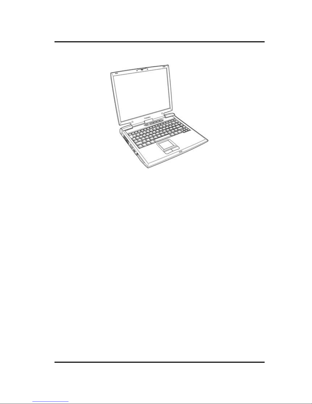
Figure 1-1 shows the front of the computer.
Figure 1-1 Front of the computer
1.1 Features 1 Hardware Overview
Satellite A 50/TECRA A2 Maintenance Manual (960-478) 1-5
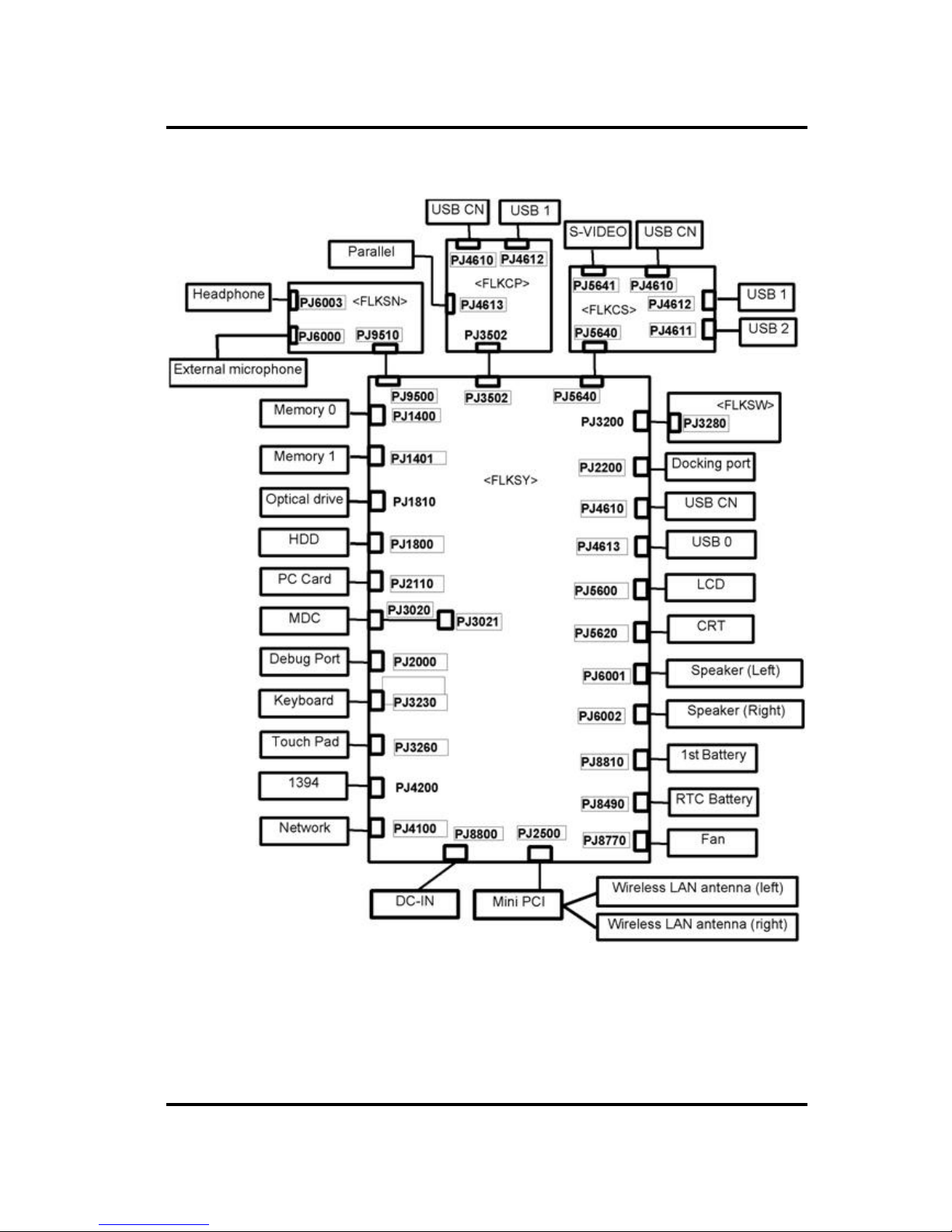
Figure 1-2 shows the system units configuration.
Figure 1-2 System units configuration
1 Hardware Overview 1.2 System Block Diagram
1-6 Satellite A50/TECRA A2 Maintenance Manual (960-478)
1.2 System Block Diagram
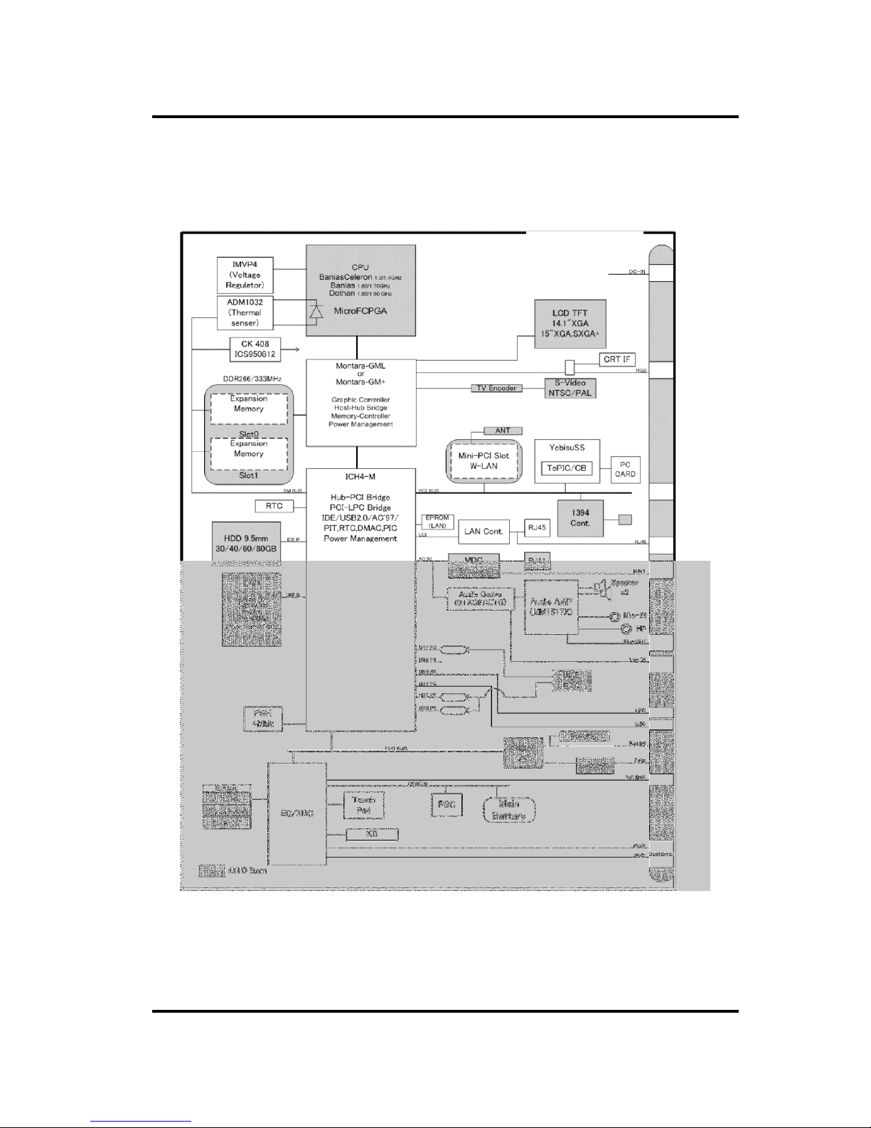
Figure 1-3 shows the system block diagram.
Figure 1-3 System Block Diagram

1.2 System Block Diagram 1 Hardware Overview
Satellite A 50/TECRA A2 Maintenance Manual (960-478) 1-7
The PC contains the following components.
q CPU
Intel® Mobile Pentium® -M model
• 1.50/1.60/1.70GHz (Internal clock: 1.50/1.60/1.70GHz, Bus: 400MHz, Core
voltage: 1.48/0.88V, Built-in NDP)
• L1 cache memory: 64KB
• L2 cache memory: 1024KB
Intel® Mobile Celeron® -M model
• 1.20/1.30/1.40GHz (Internal clock: 1.20/1.30/1.40GHz, Bus: 400MHz, Core
voltage: 1.356V, Built-in NDP)
• L1 cache memory: 64KB
• L2 cache memory: 256KB
q Memory
Two memory slots capable of accepting 256MB, 512MB or 1024MB memory
modules for a maximum of 1GB or 2GB.
• 200-pin DDR -SDRAM (PC2100/PC2700)
• Pipeline configuration
• 2.5V operation
• Support PC133
q Firmware Hub
• 4Mbit (Flash memory)
• Vcc : 3.3V±0.3V
• Vpp : 3.3V/12V

1 Hardware Overview 1.2 System Block Diagram
1-8 Satellite A50/TECRA A2 Maintenance Manual (960-478)
q Chipset
This gate array has the following elements and functions.
• North Bridge (Intel Montara-GML or Intel Montara-GM+)
− CPU interface and controller
− Host bus support
− System memory SDRAM controller
− Hub interface
− AGP interface
− Power management
− Graphic controller
• South Bridge (Intel ICH4 -M)
− LAN controller
− IDE controller
− DMA controller
− USB interface
− SM Bus interface
− Interrupt controller
− Power management
− Firmware Hub interface
− Low Pin count (LPC) interface
− Real time clock
− AC’97 interface
− Audio controller
− Hub interface
q PC card controller (YEBISUSS)
− PCI interface (PCI Revision 2.2)
− Deeper Sleep control interface
− Chipset interface
Intel serial interrupt
− Card Bus /PC card controller (Yenta Version 2.2: 1 slot)
Parallel power control (Toshiba style)
− SD memory card controller (SDHC Version 1.2)
− SD IO card controller (Version 1.1)
− Smart Card interface debug port
− Docking station interface
Q Switch control, reset control
− External device interface
FDD/IDE hot plug plug-and-play control

1.2 System Block Diagram 1 Hardware Overview
Satellite A 50/TECRA A2 Maintenance Manual (960-478) 1-9
q VGA co ntroller
Imbedded in North Bridge
q Super I/O (SMSC-made LPC-47n277-MN)
• FDC (765B FDC)
• Parallel port control (PS/2 bi-directional compatible, EPP compatible,
IEEE1284 ECP)
q Other main system chips
• EC/KBC (SMSC-made LPC microcontroller LPC47N259 x 1)
• PSC (Toshiba -made TMP87PM48U x 1)
• Thermal sensor (AnalogDevice-made ADM1032 x 1)
• Audio AMP (Mitsumi-made MM1517X x1)
• AC97-CODEC (SigmaTel-made STAC9750TG x1)
q Mini PCI (802.11b: made by Intel, 802.11a/g: made by Askey or Intel, 802.11g: made
by Intel x 1)
2.4 GHz DSSS wireless LAN card is equipped in the mini PCI card slot. Conformity
with IEEE 802.11b (WiFi). Transfer speed is maximum of 11Mbit/sec. Supports
128bit WEP.
q LAN (Intel -made Kinnereth (ED82562 x 1)
Controls LAN.
Supports 100Base-TX and 10Base-T.
q MODEM (A skey-made 1456VQL4A (INT) x 1)
Supported by MDC.
Uses secondary AC97 line.
Data and FAX transmission is available.
Supports ITU-TV.90 and V.92.
The transfer speed of data receiving is 56kbps, of data sending is 33.6kbps and of
FAX is 14.4Kbps. Actual speed depends on the quality of the line used.
Connected to telephone line through RJ11 modem jack.
1 Hardware Overview 1.3 3.5-inch USB Floppy Disk Drive
1-10 Satellite A50/TECRA A2 Maintenance Manual (960-478)
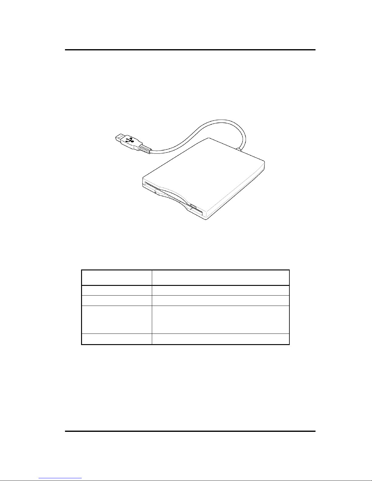
1.3 3.5-inch USB Floppy Disk Drive
This compact, lightweight and high-reliability FDD can be used with 720KB and 1.44MB
floppy disks.
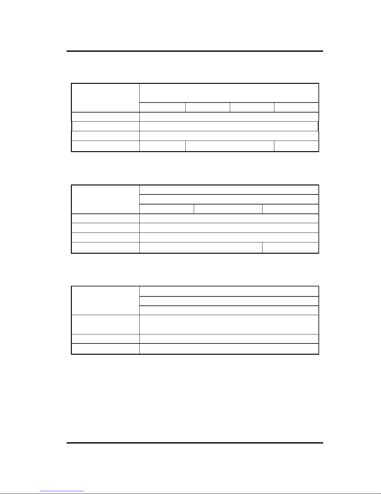
Figure 1-4 shows the 3.5-inch FDD. Table 1-1 lists the specifications.
Figure 1-4 3.5-inch USB FDD
Table 1- 1 3.5-inch USB FDD specifications
Item Specifications
Disk used 2DD 2HD
Unformatted capacity 1.0MB 2.0MB
Formatted capacity 720KB 1.44MB
Data transfer speed
( Kb/s)
250 500
Rotation speed( rpm)
300 300

1.4 2.5-inch Hard Disk Drive 1 Hardware Overview
Satellite A 50/TECRA A2 Maintenance Manual (960-478) 1-11
1.4 2.5-inch Hard Disk Drive
The computer has a compact, high-capacity HDD with a height of 9.5 mm. The HDD
contains a 2.5-inch magnetic disk and magnetic heads.
Figure 1-5 shows a view of the 2.5-inch HDD and Tables 1-2 and 1-3 list the dimensions and
specifications.
Figure 1- 5 2.5-inch HDD
Table 1-2 2.5-inch HDD dimensions (1/5)
Standard
Item
TOSHIBA
HDD2187B
HDD2188B HDD2189B HDD2190B HDD2191B HDD2193B HDD2194B
Width (mm) 69.85
Height (mm) 9.5
Depth (mm) 100.0
Weight (g) (MAX) 95
Table 1-2 2.5-inch HDD dimensions (2/5)
Standard
FUJITSU
Item
G8BC0001C410 G8BC0001C610
Width (mm) 70
Height (mm) 9.5
Depth (mm) 100.0
Weight (g) (MAX)
99
1 Hardware Overview 1.4 2.5-inch Hard Disk Drive
1-12 Satellite A50/TECRA A2 Maintenance Manual (960-478)
Table 1-2 2.5-inch HDD dimensions (3/5)
Standard
HITACHI
Item
G8BC0000Z310 G8BC0000Z311 G8BC0000Z411 G8BC0000Z611
Width (mm) 69.85
Height (mm) 9.5
Depth (mm) 100.0
Weight (g)
99 95 99
Table 1-2 2.5-inch HDD dimensions (4/5)
Standard
HITACHI
Item
G8BC00014410 G8BC00014610 G8BC00014810
Width (mm) 69.85
Height (mm) 9.5
Depth (mm) 100.0
Weight (g)
95 102 (max)
Table 1-2 2.5-inch HDD dimensions (5/5)
Standard
SEAGATE
Item
G8BC0001F410
Width (mm) 69.85
Height (mm) 9.5
Depth (mm) 100.2
Weight (g)
99
1.4 2.5-inch Hard Disk Drive 1 Hardware Overview
Satellite A 50/TECRA A2 Maintenance Manual (960-478) 1-13
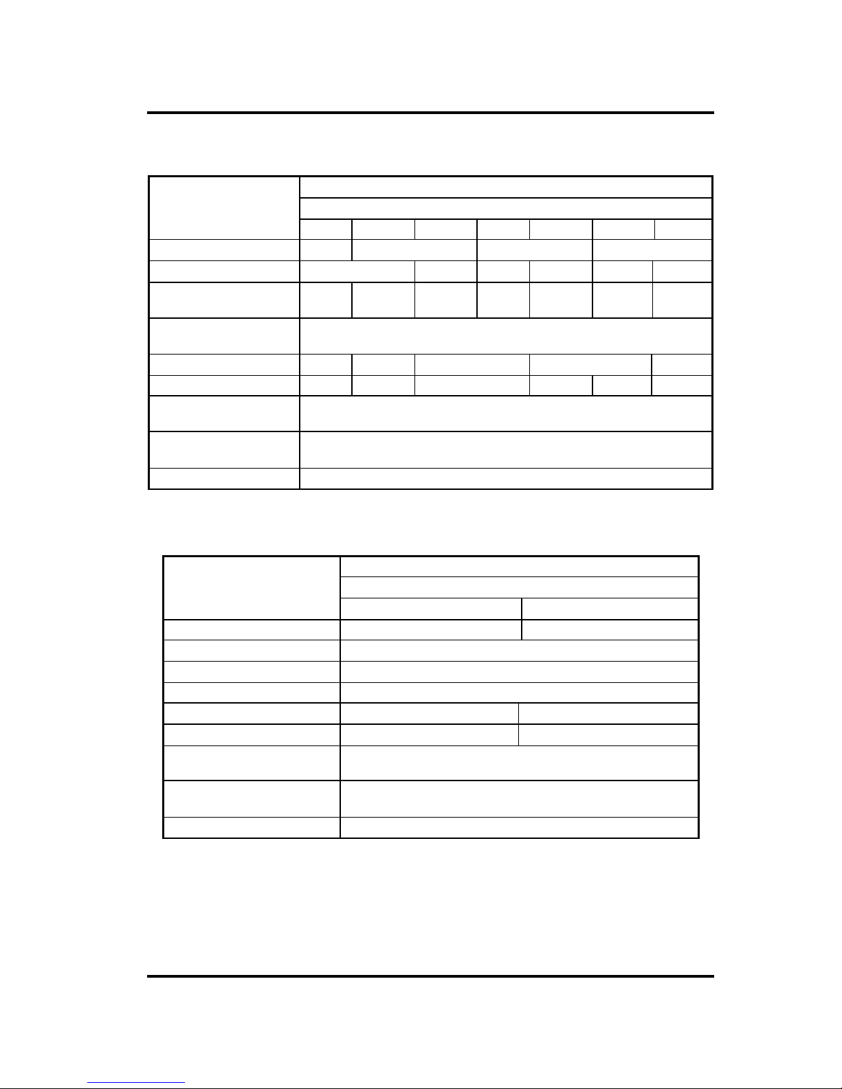
Table 1-3 2.5-inch HDD Specifications (1/5)
Specifications
Item
TOSHIBA
HDD2187B
HDD2190B HDD2193 HDD2189B HDD2194 HDD2188B HDD2191
Storage size (formatted) 20GB 40GB 60GB 80GB
Rotation speed (RPM) 4,200 5,400 4,200 5,400 4,200 5,400
Data transfer rate (MB/s) 164.6-
257.1
175.0-
341.7
154.3-
298.0
175.0-
341.7
258.0-
394.0
175.0-
341.7
233.0-
446.0
Interface transfer rate
(MB/s)
100
Storage density (Kbpi) 543 735 728 735 728
Track density (Ktpi) 72 88.1 78.9 88.8 88.1 88.8
Average random seek time
(read) (ms)
12
Average random seek time
(write) (ms)
12
Motor startup time (ms) 4
Table 1-3 2.5-inch HDD Specifications (2/5)
Specifications
Item
FUJITSU
G8BC0001C410 G8BC0001C610
Storage size (formatted) 40GB 60GB
Rotation speed (RPM) 4,200
Data transfer rate (MB/s) 443.2 (max)
Interface transfer rate (MB/s) 100
Storage density (Kbpi) 752 651
Track density (Ktpi) 92 79.8
Average random seek time
(read) (ms)
12
Average random seek time
(write) (ms)
14
Motor startup time (ms) 4.0
1 Hardware Overview 1.4 2.5-inch Hard Disk Drive
1-14 Satellite A50/TECRA A2 Maintenance Manual (960-478)
Table 1-3 2.5-inch HDD Specifications (3/5)
Specifications
HITACHI
Item
G8BC0000Z310 G8BC0000Z311 G8BC0000Z411 G8BC0000Z611
Storage size (formatted) 30GB 30GB 40GB 60GB
Rotation speed (RPM) 4,200
Data transfer rate (MB/s) 350 (max)
Interface transfer rate (MB/s) 100
Storage density (Kbpi) 712
Track density (Ktpi) 63
Average random seek time
(read) (ms)
14
Average random seek time
(write ) (ms)
12
Motor startup time (ms) 5.0
Table 1-3 2.5-inch HDD Specifications (4/5)
Specifications
HITACHI
Item
G8BC00014410 G8BC00014610 G8BC00014810
Storage size (formatted) 40GB 60GB 80GB
Rotation speed (RPM) 5,400
Data transfer rate (MB/s) 450 (max)
Interface transfer rate (MB/s) 100
Storage density (Kbpi) 712
Track density (Ktpi) 96
Average random seek time
(read) (ms)
14
Average random seek time
(write ) (ms)
12
Motor startup time (ms) 3.5
1.4 2.5-inch Hard Disk Drive 1 Hardware Overview
Satellite A 50/TECRA A2 Maintenance Manual (960-478) 1-15
Table 1-3 2.5-inch HDD Specifications (5/5)
Specifications
SEAGATE
Item
G8BC0001F410
Storage size (formatted) 40GB
Rotation speed (RPM) 4,200
Data transfer rate (MB/s) 386
Interface transfer rate (MB/s) 100
Storage density (Kbpi) 642
Track density (Ktpi) 100.7
Average random seek time
(read) (ms)
12
Average random seek time
(write ) (ms)
14
Motor startup time (ms) 3.9

1 Hardware Overview 1.5 CD-ROM Drive
1-16 Satellite A50/TECRA A2 Maintenance Manual (960-478)
1.5 CD-ROM Drive
The CD-ROM drive accommodates either 12 cm (4.72-inch) or 8 cm (3.15-inch) CD. It is a
high-performance drive that reads at maximum 24 -speed (3,600 KB per second).
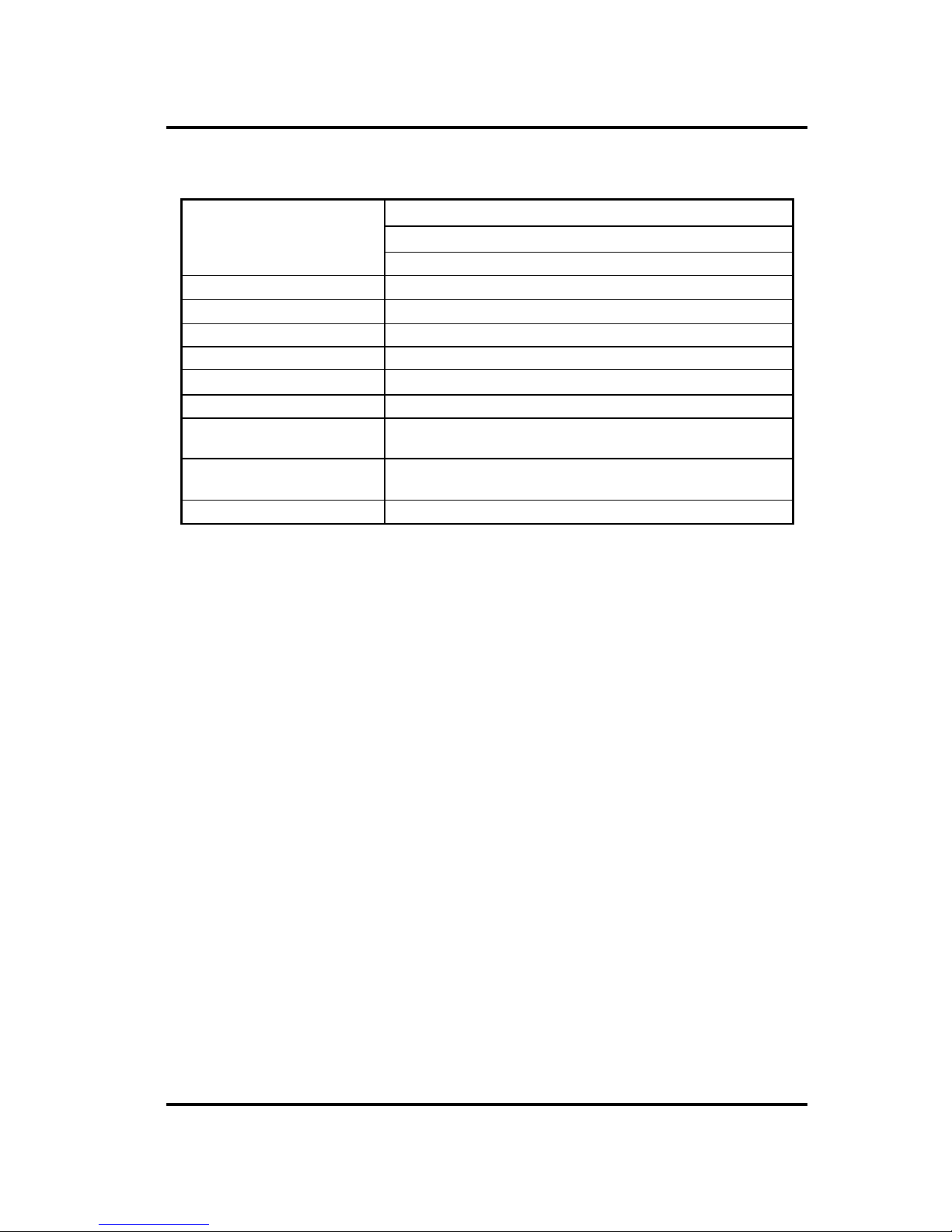
The CD-ROM drive is shown in Figure 1-6. The specifications of the CD-ROM drive are
described in Table 1-4.
Figure 1-6 CD-ROM drive
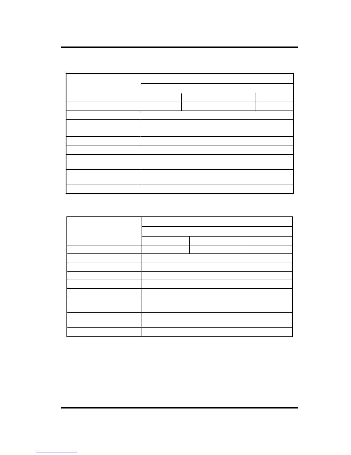
Table 1-4 CD-ROM drive specifications
Item Specifications
TEAC G8CC00005810
Data transfer rate (MB/s) 16.7 (PIO Mode 0 to 4)
16.7 (Multiple word DMA Mode 0 to 2)
33.3 (Ultra DMA)
Average random access time 110 ms
Average full stroke access time 240 ms
Data buffer capacity 128 MB
Supported formats CD-DA, CD-ROM Mode 1, Mode 2,
CD-ROM XA Mode 2 (Form 1, Form 2)
Photo CD (single/multi-session),
Enhanced CD
 Loading...