

Page 1

Toshiba Personal Computer
Satellite A20 Series
Maintenance Manual
TOSHIBA CORPORATION
File Number 960-444
ii Satellite A20 Maintenance Manual (960-444)
Page 2

Copyright
© 2003 by Toshiba Corporation. All rights reserved. Under the copyright laws, this manual
cannot be reproduced in any form without the prior written permission of Toshiba. No patent
liability is assumed with respect to the use of the information contained herein.
Toshiba Personal Computer Satellite A20 Series Maintenance Manual
First edition May 2003
Disclaimer
This manual has been validated and reviewed for accuracy. The instructions and descriptions
it contains are accurate for the TOSHIBA A20 Series Portable Personal Computer at the time
of this manual's production. However, succeeding computers and manuals are subject to
change without notice. TOSHIBA assumes no liability for damages incurred directly or
indirectly from errors, omissions or discrepancies between the computer and the manual.
Trademarks
Intel, Intel SpeedStep and Pentium are trademarks or registered trademarks of Intel
Corporation or its subsidiaries in the United States and other countries/regions.
Windows and Microsoft are registered trademarks of Microsoft Corporation.
Photo CD is a trademark of Eastman Kodak.
Bluetooth is a trademark owned by its proprietor and used by TOSHIBA under license.
Page 3
Preface
This maintenance manual describes how to perform hardware service maintenance for the
Toshiba Personal Computer Satellite A20 Series, referred to as A20 Series in this manual.
The procedures described in this manual are intended to help service technicians isolate
faulty Field Replaceable Units (FRUs) and replace them in the field.
SAFETY PRECAUTIONS
Four types of messages are used in this manual to bring important information to your
attention. Each of these messages will be italicized and identified as shown below.
DANGER: “Danger” indicates the existence of a hazard that could result in death or
serious bodily injury, if the safety instruction is not observed.
WARNING: “Warning” indicates the existence of a hazard that could result in bodily
injury, if the safety instruction is not observed.
CAUTION: “Caution” indicates the existence of a hazard that could result in property
damage, if the safety instruction is not observed.
NOTE: “Note” contains general information that relates to your safe maintenance
service.
Improper repair of the computer may result in safety hazards. Toshiba requires service
technicians and authorized dealers or service providers to ensure the following safety
precautions are adhered to strictly.
Be sure to fasten screws securely with the right screwdriver. If a screw is not fully
fastened, it could come loose, creating a danger of a short circuit, which could cause
overheating, smoke or fire.
If you replace the battery pack or RTC battery, be sure to use only the same model
battery or an equivalent battery recommended by Toshiba. Installation of the wrong
battery can cause the battery to explode.
Satellite A20 Maintenance Manual (960-444) iii
Page 4

The manual is divided into the following parts:
Chapter 1 Hardware Overview describes the Satellite A20 Series system unit and
each FRU.
Chapter 2 Troubleshooting Procedures explains how to diagnose and resolve
FRU problems.
Chapter 3 Test and Diagnostics describes how to perform test and diagnostic
operations for maintenance service.
Chapter 4 Replacement Procedures describes the removal and replacement of the
FRUs.
Appendices The appendices describe the following:
Handling the LCD module
Board layout
Pin assignments
Keyboard scan/character codes
Key layout
Wiring diagrams
BIOS Rewrite Procedures
Reliability
iv Satellite A20 Maintenance Manual (960-444)
Page 5

Conventions
This manual uses the following formats to describe, identify, and highlight terms and
operating procedures.
Acronyms
On the first appearance and whenever necessary for clarification acronyms are enclosed in
parentheses following their definition. For example:
Read Only Memory (ROM)
Keys
Keys are used in the text to describe many operations. The key top symbol as it appears on
the keyboard is printed in boldface type.
Key operation
Some operations require you to simultaneously use two or more keys. We identify such
operations by the key top symbols separated by a plus (+) sign. For example, Ctrl + Pause
(Break) means you must hold down Ctrl and at the same time press Pause (Break). If
three keys are used, hold down the first two and at the same time press the third.
User input
Text that you are instructed to type in is shown in the boldface type below:
DISKCOPY A: B:
The display
Text generated by the computer that appears on its display is presented in the type face
below:
Format complete
System transferred
Satellite A20 Maintenance Manual (960-444) v
Page 6

vi Satellite A20 Maintenance Manual (960-444)
Page 7

Table of Contents
Chapter 1 Hardware Overview
1.1 Features ......................................................................................................................1-1
1.2 System Unit Block Diagram ...................................................................................... 1-7
1.3 2.5-inch Hard Disk Drive......................................................................................... 1-14
1.4 CD-RW/DVD Drive ................................................................................................ 1-16
1.5 DVD-R/-RW Drive..................................................................................................1-19
1.6 DVD Multi Drive.....................................................................................................1-20
1.7 Keyboard..................................................................................................................1-23
1.8 TFT Color Display...................................................................................................1-24
1.9 Power Supply ........................................................................................................... 1-26
1.10 Batteries ...................................................................................................................1-28
Chapter 2 Troubleshooting Procedures
2.1 Troubleshooting ......................................................................................................... 2-1
2.2 Troubleshooting Flowchart........................................................................................ 2-3
2.3 Power Supply Troubleshooting.................................................................................. 2-7
2.4 System Board Troubleshooting................................................................................ 2-19
2.5 FDD Troubleshooting .............................................................................................. 2-33
2.6 HDD Troubleshooting ............................................................................................. 2-36
2.7 Keyboard Troubleshooting ...................................................................................... 2-41
2.8 Display Troubleshooting.......................................................................................... 2-44
2.9 CD-RW/DVD, DVD-ROM, DVD-R/-RW
and DVD Multi Drive Troubleshooting................................................................... 2-46
2.10 Modem Troubleshooting.......................................................................................... 2-48
2.11 LAN Troubleshooting.............................................................................................. 2-50
2.12 Wireless LAN Troubleshooting............................................................................... 2-52
2.13 Sound Troubleshooting............................................................................................ 2-56
2.14 SD Card Troubleshooting ........................................................................................ 2-59
Satellite A20 Maintenance Manual (960-444) vii
Page 8

Chapter 3 Tests and Diagnostics
3.1 The Diagnostic Test ................................................................................................... 3-1
3.2 Executing the Diagnostic Test ................................................................................... 3-3
3.3 Subtest Names............................................................................................................ 3-7
3.4 System Test................................................................................................................ 3-9
3.5 Memory Test............................................................................................................ 3-12
3.6 Keyboard Test.......................................................................................................... 3-14
3.7 Display Test .............................................................................................................3-18
3.8 Floppy Disk Test...................................................................................................... 3-22
3.9 Printer Test............................................................................................................... 3-24
3.10 Async Test ............................................................................................................... 3-26
3.11 Hard Disk Test ......................................................................................................... 3-27
3.12 Real Timer Test........................................................................................................ 3-30
3.13 NDP Test.................................................................................................................. 3-32
3.14 Expansion Test......................................................................................................... 3-34
3.15 CD-ROM/DVD-ROM Test ..................................................................................... 3-36
3.16 Wireless LAN Test (Agere).................................................................................... 3-37
3.17 Wireless LAN Test (Atheros) ................................................................................. 3-42
3.18 Sound/LAN/Modem Test......................................................................................... 3-45
3.19 Error Code and Error Status Names......................................................................... 3-51
3.20 Hard Disk Test Detail Status ................................................................................... 3-54
3.21 Head Cleaning.......................................................................................................... 3-56
3.22 Log Utilities .............................................................................................................3-57
3.23 Running Test............................................................................................................ 3-59
3.24 Floppy Disk Drive Utilities...................................................................................... 3-61
3.25 System Configuration .............................................................................................. 3-66
3.26 SETUP ..................................................................................................................... 3-68
Chapter 4 Replacement Procedures
4.1 General....................................................................................................................... 4-1
4.2 Battery Pack ............................................................................................................... 4-9
viii Satellite A20 Maintenance Manual (960-444)
Page 9

4.3 Optional PC Card..................................................................................................... 4-11
4.4 Optional SD Card..................................................................................................... 4-13
4.5 HDD......................................................................................................................... 4-14
4.6 Modem Daughter Card ............................................................................................ 4-18
4.7 Slim Select Bay Module .......................................................................................... 4-20
4.8 Cooling Fan.............................................................................................................. 4-24
4.9 CPU.......................................................................................................................... 4-27
4.10 Keyboard.................................................................................................................. 4-32
4.11 Memory Module ...................................................................................................... 4-36
4.12 Wireless LAN Card.................................................................................................. 4-38
4.13 Bluetooth.................................................................................................................. 4-41
4.14 Switch Board............................................................................................................ 4-43
4.15 Top Cover with Display Assembly.......................................................................... 4-45
4.16 Touch Pad ................................................................................................................ 4-48
4.17 Front Membrane ASSY ...........................................................................................4-50
4.18 USB Board ............................................................................................................... 4-52
4.19 Sound Board............................................................................................................. 4-54
4.20 RTC Battery ............................................................................................................. 4-56
4.21 DC-IN Jack .............................................................................................................. 4-58
4.22 System Board ........................................................................................................... 4-59
4.23 Sub Fan .................................................................................................................... 4-61
4.24 PC Card Slot ............................................................................................................4-63
4.25 Speakers ................................................................................................................... 4-65
4.26 Touch Pad Switch .................................................................................................... 4-67
4.27 Display Mask ...........................................................................................................4-68
4.28 FL Inverter ...............................................................................................................4-70
4.29 LCD Module ............................................................................................................ 4-72
4.30 Wireless LAN Antenna/Blutooth Antenna/Display Cover...................................... 4-76
4.31 Fluorescent Lamp..................................................................................................... 4-85
Satellite A20 Maintenance Manual (960-444) ix
Page 10

Appendices
Appendix A Handling the LCD Module ........................................................................... A-1
Appendix B Board Layout ................................................................................................ B-1
Appendix C Pin Assignments............................................................................................ C-1
Appendix D Keyboard Scan/Character Codes .................................................................. D-1
Appendix E Key Layout.....................................................................................................E-1
Appendix F Wiring Diagram ............................................................................................. F-1
Appendix G BIOS Rewrite Procedures............................................................................. G-1
Appendix H EC/KBC Rewrite Procedures........................................................................ H-1
Appendix I Reliability........................................................................................................I-1
x Satellite A20 Maintenance Manual (960-444)
Page 11

Chapter 1
Hardware Overview
Page 12

1 Hardware Overview
1-ii Satellite A20 Maintenance Manual (960-444)
Page 13

1 Hardware Overview
Chapter 1 Contents
1.1 Features.......................................................................................................................1-1
1.2 System Unit Block Diagram.......................................................................................1-7
1.3 2.5-inch Hard Disk Drive .........................................................................................1-14
1.4 CD-RW/DVD Drive .................................................................................................1-16
1.5 DVD-R/-RW Drive...................................................................................................1-19
1.6 DVD Multi Drive .....................................................................................................1-20
1.7 Keyboard ..................................................................................................................1-23
1.8 TFT Color Display ...................................................................................................1-24
1.8.1 LCD Module .......................................................................................1-24
1.8.2 FL Inverter Board ...............................................................................1-25
1.9 Power Supply............................................................................................................1-26
1.10 Batteries....................................................................................................................1-28
1.10.1 Main Battery .......................................................................................1-28
1.10.2 Battery LED (Main Battery) ...............................................................1-28
1.10.3 Battery Charging Control....................................................................1-29
1.10.4 RTC battery.........................................................................................1-30
Satellite A20 Maintenance Manual (960-444) 1-iii
Page 14

1 Hardware Overview
Figures
Figure 1-1 Front of the computer .....................................................................................1-5
Figure 1-2 System unit configuration...............................................................................1-6
Figure 1-3 System unit block diagram .............................................................................1-7
Figure 1-4 2.5-inch HDD ...............................................................................................1-14
Figure 1-5 CD-RW/DVD drive ......................................................................................1-16
Figure 1-6 DVD-R/-RW drive .......................................................................................1-19
Figure 1-7 DVD Multi drive ..........................................................................................1-20
Figure 1-8 Keyboard ......................................................................................................1-23
Figure 1-9 LCD module .................................................................................................1-24
Tables
Table 1-1 2.5-inch HDD specifications ........................................................................1-14
Table 1-2 CD-RW/DVD drive specifications ...............................................................1-17
Table 1-3 DVD-R/-RW drive specifications ................................................................1-19
Table 1-4 DVD Multi drive specifications ...................................................................1-20
Table 1-5 LCD module specifications ..........................................................................1-25
Table 1-6 FL inverter board specifications ...................................................................1-25
Table 1-7 Power supply board output rating.................................................................1-27
Table 1-8 Battery specifications ...................................................................................1-28
Table 1-9 Time required for quick charges...................................................................1-29
Table 1-10 RTC battery charging/data preservation time...............................................1-30
1-iv Satellite A20 Maintenance Manual (960-444)
Page 15

1.1 Features 1 Hardware Overview
1 Features
1.1 Features
The Toshiba Satellite A20 Personal Computer uses extensive Large Scale Integration (LSI),
and Complementary Metal-Oxide Semiconductor (CMOS) technology extensively to provide
compact size, minimum weight, low power usage and high reliability. The computer is built
and configured to order, to best meet the customer’s needs. This computer incorporates the
following features:
Processor
Intel Desktop Pentium 4 Processor •
The processor runs at one of the following speeds:
– 2.53GHz (1.525volts) / 533MHz
– 2.66GHz (1.525volts) / 533MHz
– 2.80GHz (1.525volts) / 533MHz
– 3.06GHz (1.525volts) / 533MHz
The processor incorporates a 12KB L1 cache memory and 512KB L2 cache
memory.
Memory
The computer contains no on-board memory.
Two PC2100 (266MHz) compatible DDR-SDRAM slots are available for installation
of a 128MB, 256MB, 512MB or 1GB memory module, for a total of 2GB.
HDD
Single 30GB, 40GB, 60GB or 80GB internal drive, 2.5-inch and 9.5 mm height.
USB FDD
A 3.5-inch USB FDD accommodates both 2HD (1.44MB) and 2DD (720KB) disks.
Satellite A20 Maintenance Manual (960-444) 1-1
Page 16

1 Hardware Overview 1.1 Features
CD-RW/DVD Drive
A full-size, CD-RW/DVD-ROM drive module lets you run CD/DVDs without using
an adaptor. It reads DVD-ROMs at maximum 8 speed and CD-ROMs at maximum
24 speed. It writes CD-R at up to 24 speed and CD-RW at up to 10 speed. A Mode
Control button turns power to the fixed CD-RW/DVD-ROM drive on and off so you
can use the drive as a stand-alone audio CD player. This drive supports the following
formats: Photo-CD, CD-EXTRA, CD-R, CD-RW, DVD-ROM, DVD-R, DVD-RW,
DVD-Video, DVD-RAM.
DVD-R/-RW Drive
A full-size DVD-R/-RW drive module lets you record data to rewritable CD/DVDs as
well as run either 12 cm (4.72") or 8 cm (3.15") CD/DVDs without using an adaptor.
It reads DVD-ROMs at maximum 8 speed and CD-ROMs at maximum 24 speed. It
writes CD-R at up to 16 speed, CD-RW at up to 10 speed, DVD-R and DVD-RW at
single speed. This drive supports the following formats: Photo CD, CD-R, CD-ROM,
CD-RW, CD-ROM XA, CD-DA, CD-TEXT, DVD-Video, DVD-ROM, DVD-R,
DVD-RW, DVD-RAM.
DVD-Multi Drive
A full-size, DVD Multi drive module lets you run either 12 cm (4.72") or 8 cm
(3.15") CD/DVDs without using an adaptor. It reads DVD-ROMs at maximum 8
speed and CD-ROMs at maximum 24 speed. It writes CD-R at up to 16 speed, CDRW at up to 8 speed, DVD-R and DVD-RW at single speed, and DVD-RAM at 2
speed. This drive supports the following formats: CD-ROM, CD-R, CD-RW, Photo
CD, CD-EXTRA, DVD-Video, DVD-ROM, DVD-R.
Keyboard
An easy-to-use 85(US)/86(UK)-key keyboard provides a numeric keypad overlay for
fast numeric data entry or for cursor and page control. The keyboard also includes
two keys that have special functions in Microsoft Windows XP. It supports software
that uses a 101- or 102-key enhanced keyboard.
Touch pad
A touch pad and control buttons in the palm rest enable control of the on-screen
pointer and scrolling of windows.
1-2 Satellite A20 Maintenance Manual (960-444)
Page 17

1.1 Features 1 Hardware Overview
Display
The following displays are available:
14.1-inch XGA TFT screen, 1,024×768 pixels, 16M colors •
• • 15.0-inch XGA TFT screen, 1,024×768 pixels, 16M colors
15.0-inch SXGA+ TFT screen, 1,400×1,050 pixels, 16M colors
A video controller contained on the north bridge and 4MB, 8MB, 16MB or
32MB of SMA VRAM enable an external monitor with an RGB cable to display
64k colors at a resolution of 1,600 x 1,200 pixels.
Batteries
The computer has two batteries: a lithium-ion main battery pack and RTC battery
(that backs up the Real Time Clock and CMOS memory).
Slot for optional memory
Two DDR-SDRAM (PC2100) slots are available for 128MB, 256MB, 512MB and
1GB memory modules, consisting of SDRAM chips.
Universal Serial Bus (USB)
The computer comes with three USB 2.0 ports that comply with Enhanced Host
Controller Interface (EHCI) and Open Host Controller Interface (OHCI). The USB
enables daisy-chain connection of up to 127 USB-equipped devices and 480Mbps
serial data transfer. It is designed for easy configuration by a Plug-and-Play operating
system and provides hot insertion/ejection capability.
Infrared port
The infrared port is compatible with Fast InfraRed (FIR) standards enabling cableless
1.15 Mbps, 4 Mbps, 115.2 kbps, 57.6 kbps, 38.4 kbps, 19.2 kbps or 9.6 kbps data
transfer with Infrared Data Association (IrDA) 1.1 compatible external devices.
Internal LAN
The computer is equipped with LAN circuits that support Ethernet LAN (10 megabits
per second, 10BASE-T) and Fast Ethernet LAN (100 mega bits per second, 100
BASE-Tx). It also supports Wakeup on LAN (WOL) and Magic Packet.
Satellite A20 Maintenance Manual (960-444) 1-3
Page 18

1 Hardware Overview 1.1 Features
Wireless LAN (mini PCI Card slot)
In some models, a Mini PCI Card with wireless LAN functions is available as a
dealer-installed option.
The mini PCI Card for wireless LAN is compatible with other LAN systems based on
Direct Sequence Spread Spectrum radio technology that complies with the IEEE
802.11b or a/b. It supports data transfer up to 11 Mbit/s. It has Frequency Channel
Selection (2.4GHz) and allows roaming over Multiple channels. Modem + 802.11b
and modem mini PCI cards do not support wireless LAN.
PC Card Slot
A PC Card Slot accommodates two 5mm cards (Type II) or one 10.5mm (Type III)
card, which support the PC Card Standard Release 1997 cards and are ready for
advanced cards, including PC Card 16's multifunction cards and CardBus 32-bit cards.
SD Card Slot
The computer is equipped with an SD Card slot that can accommodate Secure Digital
flash memory cards with capacities of 8MB, 16MB, 32MB, 64MB and 256MB. SD
cards let the user easily transfer data from devices, such as digital cameras and
Personal Digital Assistants, that use SD Card flash-memory. The cards have a highlevel of security and copy protection features.
Sound system
This computer supports software sound (AC97 Audio). The sound system is equipped
with AC97 Audio, a CODEC chip, stereo speakers and jacks for headphone and
external microphone. The sound system is equipped with the following:
• Stereo speakers
• Volume control knob
• Headphone jack
• External microphone jack
• Line-in jack
Video out
This video-out mini-jack enables transfer of NTSC or PAL data (video and right/left
audio) to external devices such as a TV.
1-4 Satellite A20 Maintenance Manual (960-444)
Page 19

1.1 Features 1 Hardware Overview
Internal modem
The internal modem is equipped as a modem daughter card (MDC).
The internal modem provides capability for data and fax communication and supports
ITU-TV.90. In the U.S. and Canada, V.92 is supported. For data reception it operates
at 56,000bps and for data transmission it operates at 33,600bps. For fax transmission
it operates at 14,400bps. The speed of data transfer and fax depends on analog
telephone line conditions. It has an RJ11 modem jack for connecting to a telephone
line.
The computer is shown in figure 1-1. The system unit configuration is shown in figure 1-2.
Figure 1-1 Front of the computer
Satellite A20 Maintenance Manual (960-444) 1-5
Page 20
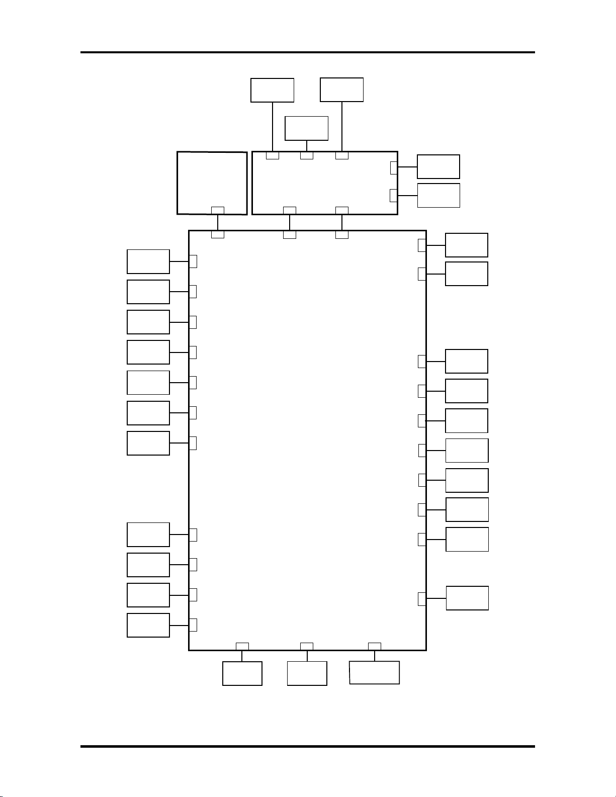
1 Hardware Overview 1.1 Features
Memory 1
Memory 2
TV
FIR
Board
PJ9610
PJ9500
PJ1400
PJ1401
PJ5600LCD 0
PJ5601LCD 1
PJ5655
SD Card
PJ2130
PJ9601
PJ9510
Headphone
External
Microphone
PJ6000
Sound Board
System Board
PJ6004
PJ9600
PJ9511
PJ6001
PJ3010
PJ9512
PJ9513
PJ8800
PJ8810
Line IN
MDC
Speaker
(Right)
Speaker
(Left)
DC-IN
1st Battery
CRT
USB
Network
HDD
ODD
PC Card
PJ5620
PJ4600
PJ4100
PJ1800
PJ1820
PJ2110
PJ3230
Keyboard
PJ3240
PAD
PJ9999
PJ9900
PJ2010
PJ8770
PJ2200
PJ3510
PJ3260
Switch Board
RTC
Battery
FAN 0
Debug port
FAN 1
Mini PCI
Parallel
Figure 1-2 System unit configuration
1-6 Satellite A20 Maintenance Manual (960-444)
Page 21
1.2 System Unit Block Diagram 1 Hardware Overview
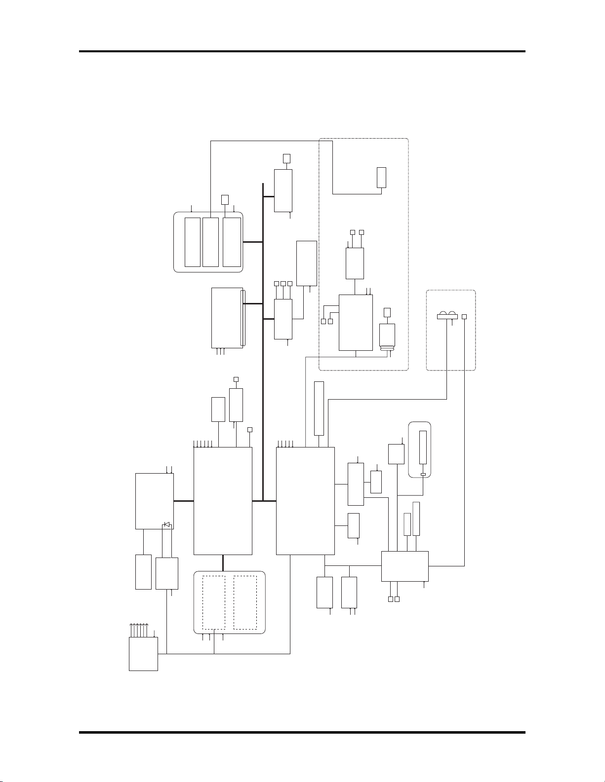
1.2 System Unit Block Diagram
Figure 1-3 is the block diagram of the system unit.
MEMCLK
AGPCLK
CPUCLK
CPU
Voltage
PCICLK
P3V
VID1.2V
DT
Northwood
Intel Pentium 4
2.53/2.66/2.8/3.06GHz
Analog
Sensor
Thermal
Regulator
48MCLK
14MCLK
P3V
256 Balls
YEBISU SS
PPV
533MHz
Devices
ADM1032
P3V
BGA
B3V
Flute
PPV
645 Balls
PCMCIA/
SD Cont.
(Pelican3)
P3V
LCD
P3V
BMV
B2.5V
B3V
B5V
North Bridge
ALi Sonoma-P4
w/Trident XP2 Graphics
266MHz
Memory
Expansion
CardBus
Slot
MCVCCA
Cont.
CardBus
(ToPIC100)
MiniPCI Slot
Wireless LAN
P5V
B3V
S-VIDEO
(TFT)
TV encoder
TVXPRESS2
CRT I/F
B3V
PCI-PCI Bridge
Host-PCI Bridge
Memory Controller
Graphics Controller
Slot0
Memory
Expansion
128/256/512MB/1GB
128/256/512MB/1GB
33MHz
Slot1
LAN Cont.
USB Port0
USB2.0 Cont.
PCI Bus
P2.5V
BGA
352 Balls
RJ45
Realtek
RTL8139DL
LAN-E3V
USB Port1
USB Port2
NEC
UPD720101
B3V
P3V
P5V
S3V
ALi M1535+
South Bridge
SMBUS
S5V
Module
Bluetooth
BT-P3V
Parallel Port
IDE, USB1.1,
PCI-South I/O bridge
SM-BUS, AC' 97 Modem/Audio,
FSNAS*
MIC
Line-IN
Secondary IDE
Primary IDE
Power management
Super I/O, PIT, DMAC, PIC,
4Mbit
BIOS ROM
P5V
HEADPHONE
SPEAKER
SND-E5V
AMP
MM1517
A4R7-P4V
P3V
Analog
Devices
AD1981B
SOUND Codec
S5V
OZ168
O2Micro
CDPLAY Cont.
HDD
P5V
RTC
bq3285
P5V
R3V
SD Card
RJ11
CD-E5V
ODD
Slot x1
MDC
B3V
3rd. I2C Bus
1st. I2C Bus
Power Switch
MCV
PSC
Int-KB
EC/KBC
Mitsubishi
Panel Switch
FIR
P3V
FSNAF*
Wireless Switch. LED
E2PROM
Main Battery
Touch PAD
K9
S3V
P3V
B2.5V
ICS
Clock Gen.
ICS951104
B1.25V
Figure 1-3 System unit block diagram
Satellite A20 Maintenance Manual (960-444) 1-7
Page 22

1 Hardware Overview 1.2 System Unit Block Diagram
The system unit is composed of the following major components:
Processor
Intel Desktop Pentium 4 Processor 2.53GHz
– Processor core speed: 2.53GHz at 1.525V
– Processor bus speed: 533MHz
– Integrated L1 cache memory: 12KB instruction cache and 8KB write-back
data cache, 4-way set associative
– Integrated L2 cache memory: 512KB ECC protected cache data array, 8-
way set associative
– Integrated NDP
Intel Desktop Pentium 4 Processor 2.66GHz
– Processor core speed: 2.66GHz at 1.525V
– Processor bus speed: 533MHz
– Integrated L1 cache memory: 12KB instruction cache and 8KB write-back
data cache, 4-way set associative
– Integrated L2 cache memory: 512KB ECC protected cache data array, 8-
way set associative
– Integrated NDP
Intel Desktop Pentium 4 Processor 2.8GHz
– Processor core speed: 2.8GHz at 1.525V
– Processor bus speed: 533MHz
– Integrated L1 cache memory: 12KB instruction cache and 8KB write-back
data cache, 4-way set associative
– Integrated L2 cache memory: 512KB ECC protected cache data array, 8-
way set associative
– Integrated NDP
Intel Desktop Pentium 4 Processor 3.06GHz
– Processor core speed: 3.06GHz at 1.525V
– Processor bus speed: 533MHz
– Integrated L1 cache memory: 12KB instruction cache and 8KB write-back
data cache, 4-way set associative
– Integrated L2 cache memory: 512KB ECC protected cache data array, 8-
way set associative
– Integrated NDP
1-8 Satellite A20 Maintenance Manual (960-444)
Page 23

1.2 System Unit Block Diagram 1 Hardware Overview
PCI Chip Set
North Bridge
ALi M1672 Northbridge with Integrated Graphic Chip
ALi PCI Northbridge Core Logic Processor Support
– Supports Intel Pentium 4 microprocessor family with host bus frequency
can be up to 400MHz
– 64-bit data bus and 32-bit addressing bus
– Optimum buffering architecture design for CPU to memory, AGP and PCI
read/write
– Flexible configuration to support back-to-back read transfer in 1QW or
2QW
– Supports back-to-back write transfer
– Supports synchronous / pseudo asynchronous clock mode between
processor and memory interface with optimized latency
Memory Support
– Supports SDR DRAM PC-100, PC-133
– Supports DDR up to 200, 266MHz
– Supports symmetrical and asymmetrical SDRAM / DDR addressing
– Supports 64, 128, 256, 512Mbit SDRAM / DDR
– Maximum memory size: 3GB
– Supports 6 memory rows with per byte access on each row
– Supports memory shadowing
– x-1-1-1-1-1-1-1 back-to-back page hit
– CAS before RAS and self refresh for SDRAM
– Pipelined SDRAM / DDR cycle control with hidden pre-charge
– Dynamic switching CKE algorithm
– Supports LVTTL / SSTL2 signal level
Advanced Mobile Power Management
– Low power cell design
– Suspend and standby modes
– Internal clock gating on each functional block
– PCIPM (H/W PCI initiated)
– AGP Busy#/Stop# and PCI Clock Run#
– ACPI and DPMS support
High Performance DirectX 7.0 3D Engine
DVD Playback
Satellite A20 Maintenance Manual (960-444) 1-9
Page 24

1 Hardware Overview 1.2 System Unit Block Diagram
PCI Bus Support
– Supports synchronous / asynchronous clock mode between the processor
bus and the PCI bus
– 32-bit Address / Data PCI bus using PCI bus driver technology
– Supports up to 5 PCI masters excluding the M1672 and PCI-to-ISA bridge
– Parity protection on all PCI bus signals
– Fully supports PCI Configuration Space Enable (CSE) protocol
– Fully compliant with PCI Rev. 2.2
– Supports delayed transaction
– Dynamic memory prefetch algorithm and programmable post write flush
algorithm
– Data Collection/Write assembly of line bursts
– Supports concurrent PCI bus burst transfer at zero wait-states
Trident CyberBlade XP Graphic Core Highly Integrated Graphics Engine
– Advanced CyberBlade XP Dual-Pixel, Quad-Texture Single-Pass 3D
rendering engine
– 128-bit internal bus interface to Core logic block
– Supports Microsoft DirectX 7.0/8.0 with Cubic Mapping
– Integrated Dual-channel LVDS transmitter
– Digital interface to external TMDS transmitter
– Digital interface to external TV encoder
– DVD hardware assist with Motion Compensation (MC) and Inverse
Discrete Cosine Transform (IDCT)
– TrueVideo with Advanced Video De-interlacing
– PC2001 Compliant
Packaging
– 645 balls in 37.5 x 37.5mm BGA package
1-10 Satellite A20 Maintenance Manual (960-444)
Page 25

1.2 System Unit Block Diagram 1 Hardware Overview
South Bridge
ALi M1535+ Southbridge
– Provides a high integration bridge between the PCI Bus and Peripheral
Bus (PCI spec. 2.2 Compliant)
– Provides Steerable PCI Interrupts for PCI Device Plug-and-Play
– Enhanced DMA Controller
– Interrupt Controller
– Counter/Timers
– Distributed DMA Supported
– PC/PCI DMA Supported
– Serialized IRQ Supported
– Low Pin Count (LPC) Host Controller
– Plug-and-Play Supported
– Built-in Keyboard Controller
– Supports up to 512 KB ROM Size Decoding PMU Features
– Built-in PCI IDE Controller
– USB Interface
– SMBus Interface
– Super I/O Interface
– Audio System
– Software Modem Interface
– 352-pin (27mm x 27mm) BGA Package
Card Controller:
• YEBISU SS
This gate array has the following functions and components.
– PCI Interface (PCI Rev. 2.2)
– Chipset Interface (Intel serial interrupt)
– CardBus/PC Card Controller (Yenta Ver. 2.2) : 1 slot
– SD memory Card Controller (SDHC Ver. 1.2 enhanced)
– SD I/O card controller (Ver. 1.1)
– SmartCard I/F / Debug port
– External device interface
– Deeper Sleep control interface
Thermo Sensor
• One ADM1032AR is used.
LAN
• One RTL8139DL chip is used
Satellite A20 Maintenance Manual (960-444) 1-11
Page 26

1 Hardware Overview 1.2 System Unit Block Diagram
KBC/EC (Keyboard Controller/Embedded Controller)
• One M306K9FCLRP chip functions as both KBC and EC.
• KBC has the following functions:
– Scan controller to check status of keyboard matrix
– Interface controller between the keyboard scan controller and the system
• EC has the following functions:
– Power supply sequence control
– System I/F
– Thermal conditions control
– Flash rewriting
PSC (Power Supply Controller)
• One TMP87PM48V chip is used.
• This controller controls the power sources.
Onboard memory: 0MB
Optional memory
Two SO-DIMM slots are available for 128, 256, 512MB and 1GB memory modules,
consisting of SDRAM chips.
• PC2100
• 3.3 volts operation
• No parity bit
• Data transfer width is 64-bit
• 128/256/512/1024 MB selectable
– 128MB: eight 128Mbit (8M x 16bit) chips
– 128MB: four 256Mbit (16M x 16bit) chips
– 256MB: eight 256Mbit (16M x 16bit) chips
– 512MB: eight 512Mbit (32M x 16bit) chips
– 1GB: eight 1Gbit (64M x 16bit) chips
Sound CODEC
• One AD1981B chip is used.
• Internal Audio Controller is integrated into the MM1535+ chip.
Both chips are used as the CODEC chip.
2
Battery E
PROM: ST24C04FM
• One ST24C04FM equivalent (128 words × 16-bit, I
This memory maintains records of battery use.
2
C-Interface) is used.
1-12 Satellite A20 Maintenance Manual (960-444)
Page 27

1.2 System Unit Block Diagram 1 Hardware Overview
Clock Generator
• One ICS951104 is used.
This device generates the system clock.
Satellite A20 Maintenance Manual (960-444) 1-13
Page 28
1 Hardware Overview 1.3 2.5-inch Hard Disk Drive
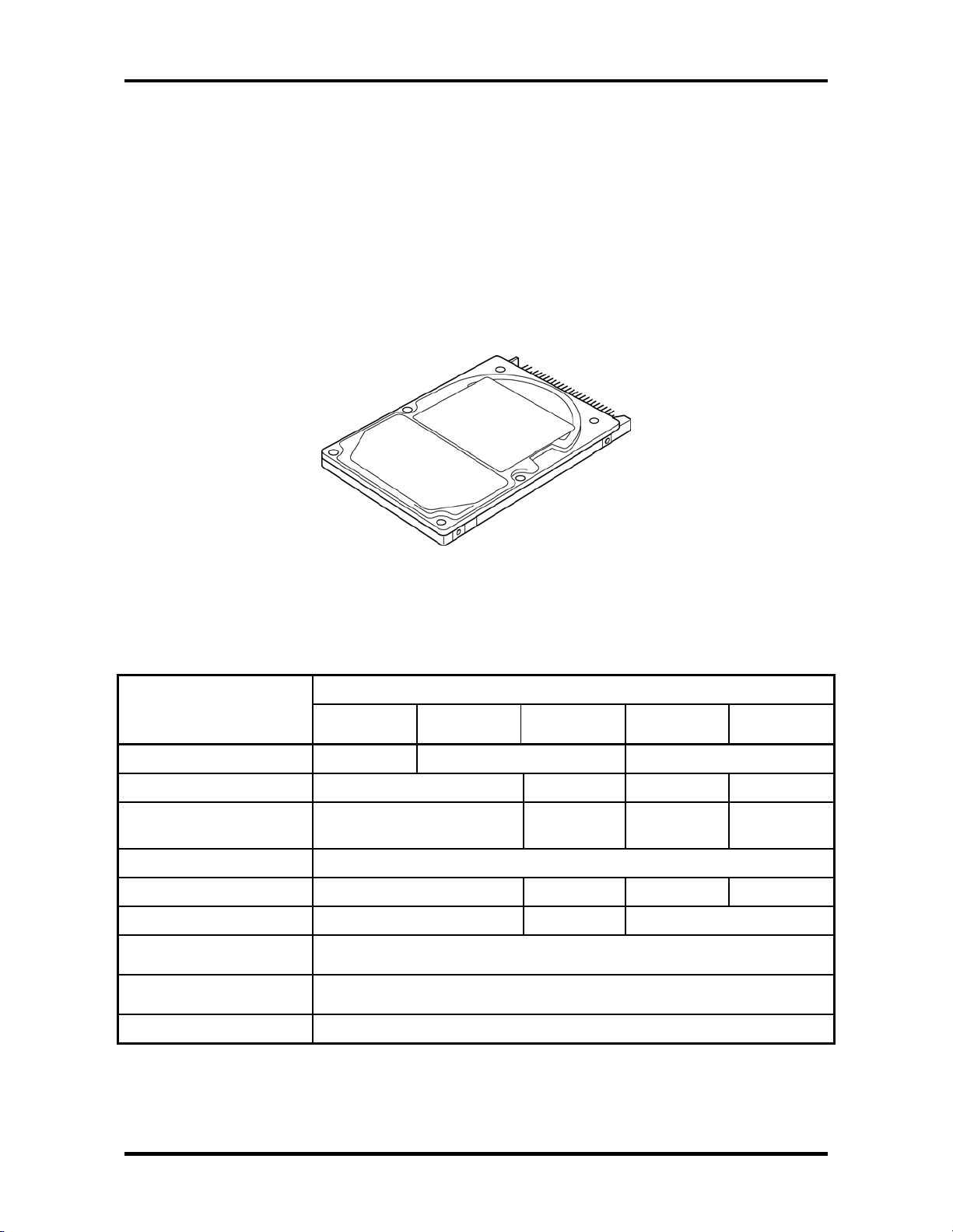
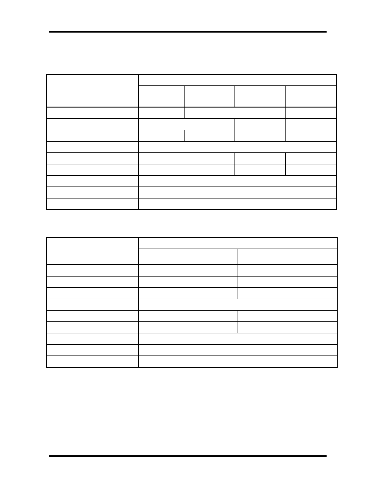
1.3 2.5-inch Hard Disk Drive
The removable HDD is a random-access, non-volatile storage device. It has a non-removable
2.5-inch magnetic disk and mini-Winchester type magnetic heads. The computer supports a
30GB, 40GB, 60GB or 80GB HDD.
The HDD is shown in figure 1-4. The specifications are listed in table 1-1.
Storage size (formatted)
Speed (RPM)
Data transfer speed (Mbits/s)
Interface transfer rate (MB/s)
Storage density (Kbpi)
Track density (Ktpi)
Average random seek time
(read) (ms)
Average random seek time
(write) (ms)
Motor start up time (ms)
Figure 1-4 2.5-inch HDD
Table 1-1 2.5-inch HDD specifications (1/3)
Specifications Parameter
TOSHIBA
HDD2181B
30 40 60
154.3 – 298.0 200.8 –
TOSHIBA
HDD2182B
TOSHIBA
HDD2171B
4.200 5.400 4.200 5.400
333.2
100
618 607 618 632
78.9 57.1 78.9
12
-
4
TOSHIBA
HDD2183B
154.3 –
298.0
TOSHIBA
HDD2184B
202.9 –
373.3
1-14 Satellite A20 Maintenance Manual (960-444)
Page 29
1.3 2.5-inch Hard Disk Drive 1 Hardware Overview
Table 1-1 2.5-inch HDD specifications (2/3)
Parameter
Storage size (formatted)
Speed (RPM)
Data transfer speed (Mbits/s)
Interface transfer rate (MB/s)
Storage density (Kbpi)
Track density (Kbpi)
Average random seek time (read) (ms)
Average random seek time (write) (ms)
Motor start up time (ms)
Table 1-1 2.5-inch HDD specifications (3/3)
Storage size (formatted)
Speed (RPM)
Data transfer speed (Mbits/s)
Interface transfer rate (MB/s)
Storage density (Kbpi)
Track density (Ktpi)
Average random seek time (read) (ms)
Average random seek time (write) (ms)
Motor start up time (ms)
Specifications
HITACHI
G8BC0000F310
HITACHI
G8BC0000F410
G8BC0000Z410
G8BC00009110
HITACHI
HITACHI
G8BC0000F610
30 40 60
4.200 5.400 4.200
22.1 – 42.8 19.4 – 37.1 27.8 – 44.1 22.1 – 42.8
100 (MAX Ultra DMA mode)
716 644 (MAX) 612 716 (MAX)
70.0 63.0 70.0
13
-
5
Specifications Parameter
TOSHIBA
HDD2188B
HITACHI
G8BC0000Z810
80 80
4200 4200
350 350
100 (MAX Ultra DMA mode)
712 712
96 96
12
-
4
Satellite A20 Maintenance Manual (960-444) 1-15
Page 30
1 Hardware Overview 1.4 CD-RW/DVD Drive
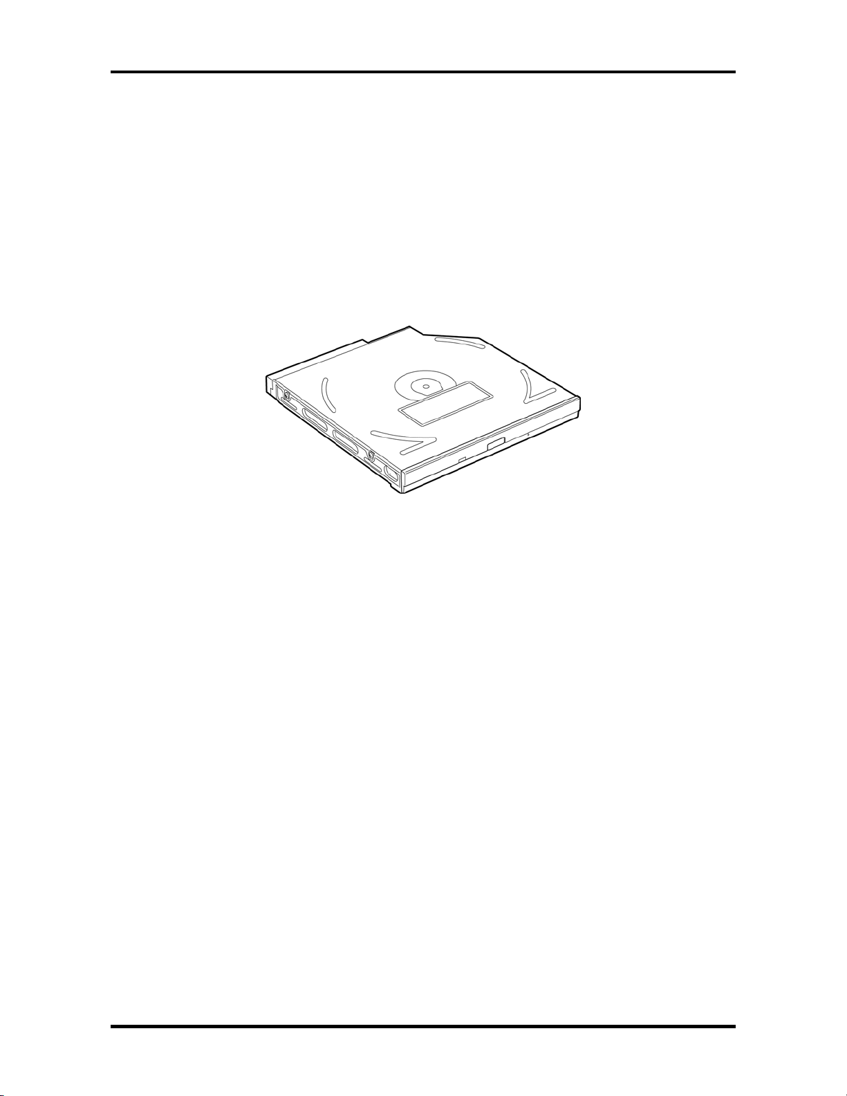
1.4 CD-RW/DVD Drive
A full-size, CD-RW/DVD-ROM drive module lets you run CD/DVDs without using an
adaptor. It reads DVD-ROMs at maximum 8 speed and CD-ROMs at maximum 24 speed. It
writes CD-R at up to 24 speed and CD-RW at up to 10 speed. A Mode Control button turns
power to the fixed CD-RW/DVD-ROM drive on and off so you can use the drive as a standalone audio CD player.
The CD-RW/DVD drive is shown in figure 1-5. Specifications for the CD-RW/DVD drive
are described in table 1-2.
Figure 1-5 CD-RW/DVD drive
1-16 Satellite A20 Maintenance Manual (960-444)
Page 31

1.4 CD-RW/DVD Drive 1 Hardware Overview
Table 1-2 CD-RW/DVD drive specifications (1/4)
Item
Specifications
TEAC G8CC0000Q410
Transfer rate
access time
(msec.)
Data Buffer Capacity 2MB
Supported Formats CD: CD-DA, CD-ROM Mode1, Mode2, CD-ROM XA
Read (CD-ROM) 1,545 to 3,600 KB/sec.
Read (DVD-ROM) 4,469 to 10,816 KB/sec.
Write (CD-R) -
Write (CD-RW) -
CD-ROM 90 Average
DVD-ROM 110
Mode 2 (Form 1, Form 2), Photo CD (single/multisession), Enhanced CD, CD-TEXT
DVD: DVD-ROM, DVD-Video, DVD-R (General,
Authoring) DVD-RAM (4.7GB, 2.6GB)
Table 1-2 CD-RW/DVD drive specifications (2/4)
Item
Specifications
Panasonic G8CC00010410
Transfer rate
access time
(msec.)
Data Buffer Capacity 2MB
Supported Formats CD: CD-DA, CD-ROM, CD-ROM XA, CD-R, CD-RW,
Satellite A20 Maintenance Manual (960-444) 1-17
Read (CD-ROM) MAX 8x CAV (MAX 10,800KB/sec.)
Read (DVD-ROM) MAX 24x CAV (MAX 3,600KB/sec.)
Write (CD-R) 4x, 8x (CLV), MAX 16x, MAX 24x (ZCLV)
Write (CD-RW) 4x (CLV)
CD-ROM 130 Average
DVD-ROM 180
Photo CD, Video CD, CD-EXTRA (CD+), CDTEXT
DVD: DVD-Video, DVD-ROM, DVD-R (3.9GB, 4.7GB),
DVD-RW, DVD-RAM (4.7GB)
Page 32

1 Hardware Overview 1.4 CD-RW/DVD Drive
Table 1-2 CD-RW/DVD drive specifications (3/4)
TEAC G8CC0001D410
Item DVD-ROM
(Play mode)
ATAPI Burst (Mbytes/s) 33.3 (Ultra DMA mode 2)
16.7 (PIO Mode 4, Multi word DMA mode 2)
Access time (ms)
Average 1/3 Stroke Access
Data Buffer Capacity (Mbytes) 2
Supported Format DVD:
DVD-ROM, DVD-VIDEO, DVD-R (read)
CD:
CD-DA, CD-Text, Photo CD,
CD-ROM Mode 1/Mode 2,
CD-ROM XA Mode 2 (Form 1, Form 2),
Enhanced CD (CD-EXTRA),
CD-G (Audio CD only),
Addressing Method 2
180
CD-ROM
(Play mode)
130
Table 1-2 CD-RW/DVD drive specifications (4/4)
TOSHIBA SD-R2212
CD-R/CD-RW
(Record mode)
-
CD-DA, CD-Text,
Photo CD, CDROM Mode 1/
Mode 2, CD-ROM
XA Mode 2 (Form
1, Form 2),
Enhanced CD
(CD-EXTRA),
CD-G (Audio CD
only), Addressing
Method 2
Item DVD-ROM mode CD-ROM mode CD-R/CD-RW
ATAPI Burst (Mbytes/s) 33.3 (Ultra DMA mode 2)
16.6 (PIO Mode 4, Multi-word DMA mode 2)
Access time (ms)
1/3 Stroke Access (typ.)
Data Buffer Capacity (Mbytes) 2
Supported Formats CD:
CD-DA, CD-ROM, CD-R/W, CD-R, CDROM XA (except ADPCM),
CD-I Ready, Photo CD (Multi session),
Video CD, CD-Extra (CD+), CD-text
DVD:
DVD-VIDEO, DVD-ROM, DVD-R
140
120
(Write)
-
CD-R, CD-RW
1-18 Satellite A20 Maintenance Manual (960-444)
Page 33

1.5 DVD-R/-RW Drive 1 Hardware Overview
1.5 DVD-R/-RW Drive
A full-size DVD-R/-RW drive module lets you record data to rewritable CD/DVDs as well
as run either 12 cm (4.72") or 8 cm (3.15") CD/DVDs without using an adaptor. It reads
DVD-ROMs at maximum 8 speed and CD-ROMs at maximum 24 speed. It writes CD-R at
up to 16 speed, CD-RW at up to 10 speed, DVD-R and DVD-RW at single speed. The DVDR/-RW drive is shown in figure 1-6. Specifications for the DVD-R/-RW drive are described
in table 1-3.
Figure 1-6 DVD-R/-RW drive
Table 1-3 DVD-R/-RW drive specifications
Item
DVD-ROM CD-ROM DVD-RAM (Write)
Transfer rate (Kbytes/s) 33.3 (Ultra DMA)
16.7 (PIO mode 4, Multiple word DMA transfer mode 2)
Access time (ms)
Average Random Access
Average Full Stroke Access
Average Full Stroke Access
Data Buffer Capacity (Mbytes) 2
Supported Formats DVD-ROM,
DVD-R,
DVD-RW,
DVD-RAM
100
95
160
Specifications
TOSHIBA G8CC0000ZD10
95
90
160
CD-DA, CD+ (E)G,
CD-MIDI,
CD-TEXT,
CD-ROM,
CD-ROM XA,
CD-I, CD-I Bridge,
Multi session CD,
CD-R, CD-RW
170
120
350
DVD-ROM
DVD-RW (Ver.1.1)
Satellite A20 Maintenance Manual (960-444) 1-19
Page 34

1 Hardware Overview 1.6 DVD Multi Drive
1.6 DVD Multi Drive
A full-size, DVD Multi drive module lets you run either 12 cm (4.72") or 8 cm (3.15")
CD/DVDs without using an adaptor. It reads DVD-ROMs at maximum 8 speed and CDROMs at maximum 24 speed. It writes CD-R at up to 16 speed, CD-RW at up to 8 speed,
DVD-R and DVD-RW at single speed, and DVD-RAM at 2 speed.
The DVD Multi drive is shown in figure 1-7. Specifications for the DVD-Multi drive are
listed in table 1-4.
Figure 1-7 DVD Multi drive
Table 1-4 DVD Multi drive specifications (1/2)
TEAC G8CC00013410 Item
DVD-ROM mode CD-ROM mode CD-R/CD-RW
ATAPI Burst (Mbytes/s) 33.3 (Ultra DMA mode 2)
16.7 (PIO Mode 4, Multi word DMA mode 2)
Access time (ms)
1/3 Stroke Access (typ.)
Data Buffer Capacity (Mbytes) 2
Supported Formats CD: CD-DA, CD-ROM Mode1, Mode2,
CD-R/W, CD-R, CD-ROM XA
130
Mode2 (Form1,Form2),
Photo CD (Single/multi-session),
CD-TEXT, Enhanced CD
110
(Write)
-
CD-R, CD-RW
DVD: DVD-VIDEO, DVD-ROM,
DVD-R (General, Authoring),
DVD-RAM
1-20 Satellite A20 Maintenance Manual (960-444)
Page 35

1.6 DVD Multi Drive 1 Hardware Overview
Table 1-4 DVD-Multi drive specifications (2/2)
Panasonic G8CC00012410 Item
DVD-ROM mode CD-ROM mode CD-R/CD-RW
(Write)
ATAPI Burst (Mbytes/s) 33.3 (Ultra DMA mode 2)
16.6 (PIO Mode 4, Multi-word DMA mode 2)
Access time (ms)
1/3 Stroke Access (typ.)
Data Buffer Capacity (Mbytes) 2
Supported Formats CD: CD-DA, CD-ROM, CD-R/W, CD-R,
DVD:DVD-VIDEO, DVD-ROM,
180
CD-ROM XA (except ADPCM),
CD-I Ready, Photo CD (Multi
session), Video CD, CD-EXTRA
(CD+), CD-TEXT
DVD-R (3.9GB, 4.7GB),
DVD-RW (Ver.1.1), DVD-RAM
130
-
CD-R, CD-RW
Satellite A20 Maintenance Manual (960-444) 1-21
Page 36

Page 37

1.7 Keyboard 1 Hardware Overview
1.7 Keyboard
The keyboard is mounted 85(US)/86(UK) keys that consist of character key and control key,
and in conformity with JIS. The keyboard is connected to membrane connector on the system
board and controlled by the keyboard controller.
Figure1-8 is a view of the keyboard.
See Appendix E about a layout of the keyboard.
Figure 1-8 Keyboard
Satellite A20 Maintenance Manual (960-444) 1-23
Page 38

1 Hardware Overview 1.8 TFT Color Display
1.8 TFT Color Display
The TFT color display consists of 14.1/15.0-inch XGA/SXGA+ LCD module and FL
inverter board.
1.8.1 LCD Module
The LCD module used for the TFT color display uses a backlight as the light source and can
display a maximum of 262,144 colors with 1,024 x 768 or 1,400 x 1,050 resolution. The
M1672 can control both internal and external XGA- or SXGA+- support displays
simultaneously.
Figure 1-9 shows a view of the LCD module and Table 1-5 lists the specifications.
Figure 1-9 LCD module
1-24 Satellite A20 Maintenance Manual (960-444)
Page 39

1.8 TFT Color Display 1 Hardware Overview
Table 1-5 LCD module specifications (14.1-inch XGA TFT) (1/3)
Specifications Item
G33C0000
L110
G33C0000
G110
G33C0000
M110
G33C0000
Q110
VF2058
P01
VF2062
P01
Number of Dots 1,024 (W) x 768 (H)
Dot spacing (mm) 0.297 (H) x 0.297 (V)
Display range (mm) 304.128 (H) x 228.096 (V)
Table 1-5 LCD module specifications (15.0-inch XGA TFT) (2/3)
Specifications Item
G33C0000L110 G33C0000G110 G33C0000M110 G33C0000Q110
Number of Dots 1,024 (W) x 768 (H)
Dot spacing (mm) 0.297 (H) x 0.297 (V)
Display range (mm) 304.128 (H) x 228.096 (V)
Table 1-5 LCD module specifications (15.0-inch SXGA + TFT) (3/3)
Specifications Item
G33C0000P110 G33C0000N110 G33C0000R110
Number of Dots 1,400 (W) x 1,050 (H)
Dot spacing (mm) 0.2175 (H) x 0.2175 (V)
Display range (mm) 304.5 (H) x 228.375 (V)
1.8.2 FL Inverter Board
The FL inverter board supplies a high frequency current to illuminate the LCD module FL.
Table 1-6 lists the FL inverter board specifications.
Table 1-6 FL inverter board specifications
Item Specifications
Voltage (V) DC 5 Input
Power (W) 7
Output
Voltage (V) 750
Current (mA) 6.00
Power (mA) 5W/7VA
Satellite A20 Maintenance Manual (960-444) 1-25
Page 40

1 Hardware Overview 1.9 Power Supply
1.9 Power Supply
The power supply distributes many different voltages to the system board and performs the
following functions:
1. Input port management
• AC adaptor connection
• Battery pack installation
• The voltage of AC adaptor (both IN and OUT)
2. Power supply internal control
• Battery pack charging status (ON/OFF)
• Controls DC voltage output by AC Adaptor
• Regulates power supply to system components (load and logic circuits)
• Controls circuit breakers in event of a power supply malfunction
3. Management of power to logic circuits
• Controls power to the CPU
• Regulates power supplied to gate arrays
• Controls ON/OFF power
4. Status indicators
• DC IN LED
• Battery LED
5. External device interface
2
• Monitors I
C bus connections through EC/KBC on the system board.
• Transmits the power supply mode.
6. Monitors power output
• Power to systems components (load and logic circuits)
• Battery pack voltage, overvoltage and I/O current
• Battery pack internal temperature
1-26 Satellite A20 Maintenance Manual (960-444)
Page 41

1.9 Power Supply 1 Hardware Overview
The power supply output rating is specified in table 1-7.
Table 1-7 Power supply board output rating
Use Name
CPU,M1672 PPV 1.55-1.25 NO NO NO
CPU
M1672,Memory 2R5-B2V 2.5 YES NO NO
M1535+,Clock Generator 2R5-P2V 2.5 NO NO NO
Memory 1R25-B1V 1.25 YES NO NO
Memory
M1672 BMV 3.3 YES NO NO
LAN LAN-E3V 3.3 YES YES NO
LAN
M1672,YEBISUSS-GA,Mini PCI,PCCard(s),uPD720101,TVXPRESS2
M1535+,Clock
Generator,Memory,Mini PCI
LCD PNL-P3V 3.3 NO NO NO
VID1R2-
P1V
MR1R25-
B1V
LAN-
E2R5V
B3V 3.3 YES NO NO
P3V 3.3 NO NO NO
Voltage
(V)
1.2 NO NO NO
1.25 YES NO NO
2.5 YES YES NO
Power supplied Yes/No
Stand by Power off No battery
USB Power E5V 5.0 YES NO NO
M1672,PC-Card(s) B5V 5.0 YES NO NO
M1535+,BIOS,HDD,Mini
PCI,Keyboard,TouchPad,FAN,LEDs
ODD CD-E5V 5.0 YES YES NO
FL-inv FL-P5V 5.0 NO NO NO
SD card SD-B3V 3.3 YES NO NO
MDC MDC-B3V 3.3 YES NO NO
CRT DDC-P5V 5.0 NO NO NO
Sound SND-E5V 5.0 YES YES NO
Sound
Sound A4R7-P4V 4.7 NO NO NO
Pull-ups 15-EBV 9.0-11.5 YES NO NO
FAN FANVCC 0-5.0 NO NO NO
EC/KBC,M1535+,OZ168 S3V 5.0 YES YES NO
M1535+,OZ168,LEDs,Battery S5V 5.0 YES YES NO
PSC MCV 5.0 YES YES NO
RTC(CLK 32kHz) R3V 2.0-3.5 YES YES YES
P5V 5.0 NO NO NO
CDA4R7-
E4V
4.7 YES YES NO
Satellite A20 Maintenance Manual (960-444) 1-27
Page 42

1 Hardware Overview 1.10 Batteries
1.10 Batteries
The computer has two types of batteries:
Main battery pack
RTC battery
The battery specifications are listed in table 1-8.
Table 1-8 Battery specifications
Battery name Material Output voltage Capacity
Main battery Lithium-Ion 10.8 V 8,400 mAh
RTC battery NiMH 3.0 V 17mAh
1.10.1 Main Battery
The removable main battery pack is the computer’s main power source when the AC adaptor
is not attached. When the main battery is fully charged, it can power the computer for the
following duration:
Power ON about 2.5 to 4 hours (Normal Mode)
1.10.2 Battery LED (Main Battery)
The battery LED displays the status of the battery pack. The battery LED on the computer
displays the status of the main battery.
Orange Main battery is charging. (with AC Adaptor)
Green Main battery is fully charged. (with AC Adaptor)
Orange / Flashing Power ON (without AC Adaptor)
Main battery charge is low.
LED Off Any other condition
1-28 Satellite A20 Maintenance Manual (960-444)
Page 43

1.10 Batteries 1 Hardware Overview
1.10.3 Battery Charging Control
Battery charging is controlled by a power supply microprocessor mounted on the system
board. The power supply microprocessor controls whether the charge is on or off and detects
a full charge when the AC adaptor and battery are attached to the computer. The system
charges the battery using quick charge or trickle charge.
Battery Charge
When the AC adaptor is attached, battery charge starts.
The times required for quick charges are listed in table 1-9.
Table 1-9 Time required for quick charges
Status Charging time
Power off About 3.5 hours
Power on 3.5 to 12.5 hours or longer
NOTE: The time required for quick charge when power is on is affected by the amount of
power the system is consuming. Use of the fluorescent lamp and frequent disk access
consumes power and lengthens the charge time.
If any of the following occurs, the battery charge stops.
1. The battery becomes fully charged.
2. The AC adaptor or battery is removed.
3. The AC adaptor or battery voltage is abnormal
4. The charging current is abnormal.
Detection of full charge
A full charge is detected when the battery is charging, and under any of the following
conditions:
1. The battery charging current drops under the predetermined limit.
2. The charging time exceeds the limit.
3. The battery’s temperature exceeds 60°C.
Satellite A20 Maintenance Manual (960-444) 1-29
Page 44

1 Hardware Overview 1.10 Batteries
1.10.4 RTC battery
The RTC battery provides power to keep the current date, time and other setup information
in memory while the computer is turned off. Table 1-10 lists the charging time and data
preservation period of the RTC battery. The adapter or main battery charges the RTC battery,
while the computer is powered on.
Table 1-10 RTC battery charging/data preservation time
Status Time
Charging Time (power on) About 8 hours
Data preservation period (full charge) 1 month
1-30 Satellite A20 Maintenance Manual (960-444)
Page 45

Chapter 2
Troubleshooting Procedures
Page 46

2 Troubleshooting Procedures
2-ii Satellite A20 Maintenance Manual (960-444)
Page 47

2 Troubleshooting Procedures
Chapter 2 Contents
2.1 Troubleshooting ......................................................................................................... 2-1
2.2 Troubleshooting Flowchart........................................................................................ 2-3
2.3 Power Supply Troubleshooting ................................................................................. 2-7
Procedure 1 Power Status Check ..................................................................... 2-7
Procedure 2 Error Code Check ........................................................................ 2-9
Procedure 3 Connection Check ...................................................................... 2-16
Procedure 4 Quick Charge Check .................................................................. 2-17
Procedure 5 Replacement Check ................................................................... 2-18
2.4 System Board Troubleshooting ............................................................................... 2-19
Procedure 1 Message Check .......................................................................... 2-20
Procedure 2 Printer Port LED Check on Boot Mode ..................................... 2-22
Procedure 3 Diagnostic Test Program Execution Check ............................... 2-31
Procedure 4 Replacement Check ................................................................... 2-32
2.5 FDD Troubleshooting .............................................................................................. 2-33
Procedure 1 FDD Head Cleaning Check ....................................................... 2-33
Procedure 2 Diagnostic Test Program Execution Check ............................... 2-34
Procedure 3 Connector Check and Replacement Check................................ 2-35
2.6 HDD Troubleshooting ............................................................................................. 2-36
Procedure 1 Message Check .......................................................................... 2-36
Procedure 2 Partition Check .......................................................................... 2-37
Procedure 3 Format Check............................................................................. 2-38
Procedure 4 Diagnostic Test Program Execution Check ............................... 2-39
Procedure 5 Connector Check and Replacement Check................................ 2-40
2.7 Keyboard Troubleshooting ...................................................................................... 2-41
Procedure 1 Diagnostic Test Program Execution Check ............................... 2-41
Procedure 2 Connector and Replacement Check ........................................... 2-42
Satellite A20 Maintenance Manual (960-444) 2-iii
Page 48

2 Troubleshooting Procedures
2.8 Display Troubleshooting.......................................................................................... 2-44
Procedure 1 External Monitor Check............................................................. 2-44
Procedure 2 Diagnostic Test Program Execution Check ............................... 2-44
Procedure 3 Connector and Replacement Check ........................................... 2-45
2.9 CD-RW/DVD, DVD-ROM, DVD-R/RW
and DVD Multi Drive Troubleshooting ............................................................... 2-46
Procedure 1 Drive Cleaning Check................................................................ 2-46
Procedure 2 Diagnostic Test Program Execution Check ............................... 2-46
Procedure 3 Connector Check and Replacement Check................................ 2-47
2.10 Modem Troubleshooting.......................................................................................... 2-48
Procedure 1 Diagnostic Test Program Execution Check ............................... 2-48
Procedure 2 Connector Check and Replacement Check................................ 2-49
2.11 LAN Troubleshooting.............................................................................................. 2-50
Procedure 1 Diagnostic Test Program Execution Check ............................... 2-50
Procedure 2 Connector Check and Replacement Check................................ 2-51
2.12 Wireless LAN Troubleshooting............................................................................... 2-52
Procedure 1 Transmitting-Receiving Check .................................................. 2-52
Procedure 2 Antennas’ Connection Check .................................................... 2-53
Procedure 3 Antenna Check........................................................................... 2-54
Procedure 4 Replacement Check ................................................................... 2-55
2.13 Sound Troubleshooting............................................................................................ 2-56
Procedure 1 Diagnostic Test Program Execution Check ............................... 2-56
Procedure 2 Connector Check........................................................................ 2-57
Procedure 3 Replacement Check ................................................................... 2-58
2.14 SD Card Troubleshooting ........................................................................................ 2-59
Procedure 1 Check on Windows XP Pro/Home ............................................ 2-59
Procedure 2 Connector/Replacement Check.................................................. 2-59
2-iv Satellite A20 Maintenance Manual (960-444)
Page 49

2 Troubleshooting Procedures
Figures
Figure 2-1 Troubleshooting flowchart................................................................................. 2-4
Figure 2-2 Printer port LED............................................................................................... 2-22
Figure 2-3 Antenna test jig ................................................................................................ 2-54
Tables
Table 2-1 Battery LED ........................................................................................................ 2-7
Table 2-2 DC IN LED.......................................................................................................... 2-8
Table 2-3 Printer port LED boot mode status.................................................................... 2-23
Table 2-4 FDD error code and status................................................................................. 2-34
Table 2-5 Hard disk drive error code and status................................................................ 2-39
Satellite A20 Maintenance Manual (960-444) 2-v
Page 50

2 Troubleshooting Procedures
2-vi Satellite A20 Maintenance Manual (960-444)
Page 51

2.1 Troubleshooting 2 Troubleshooting Procedures
2
2.1 Troubleshooting
Chapter 2 describes how to determine if a Field Replaceable Unit (FRU) in the computer is
causing the computer to malfunction. The FRUs covered are:
1. System Board 5. Display 9. Wireless LAN
2. Floppy Disk Drive 6. CD/DVD/Multi Drive 10. Sound components
3. Hard Disk Drive 7. Modem 11. SD card
4. Keyboard 8. LAN
The Diagnostics Disk operations are described in Chapter 3. Detailed replacement procedures
are given in Chapter 4.
The following tools are necessary for implementing the troubleshooting procedures:
1. Diagnostics Disk
2. Phillips screwdriver (2 mm)
3. Toshiba MS-DOS system disk(s)
(You must install the following onto the disk: SYS.COM, FORMAT.COM, FDISK.COM
and FDISK.EXE)
4. 2DD or 2HD formatted work disk for floppy disk drive testing
5. Cleaning kit for floppy disk drive troubleshooting
6. Cleaning kit for CD-RW/DVD, DVD-ROM, DVD-R/-RW and DVD Multi Drive
troubleshooting
7. Printer port LED
8. Printer port wrap around connector
9. PC Card wrap around card
10. Multimeter
11. External monitor
12. PS/2 or compatible keyboard
13. PS/2 or compatible mouse
14. Multimedia sound system with line-in and line-out ports
15. Headphone
16. Microphone
17. USB test module and USB cable
18. TOSHIBA CD-ROM TEST DISK (ZA1217P01/P000204190)
19. DVD-ROM TSD-1 (TOSHIBA EMI DVD Test Media)
Satellite A20 Maintenance Manual (960-444) 2-1
Page 52

2 Troubleshooting Procedures 2.1 Troubleshooting
20. CD-RW media that supports four-speed writing and is formatted with DirectCD (media
manufactured by RICOH or Mitsubishi Chemical are recommended).
21. RJ11 connector checker and modular cable or RJ11 connector checker LED
22. LAN wraparound connector
23. Music CD
24. DVD that isn’t a test media
2-2 Satellite A20 Maintenance Manual (960-444)
Page 53

2.2 Troubleshooting Flowchart 2 Troubleshooting Procedures
2.2 Troubleshooting Flowchart
Use the flowchart in Figure 2-1 as a guide for determining which troubleshooting procedures to
execute. Before going through the flowchart steps, verify the following:
Ask the user if a password is registered and, if it is, ask him or her to enter the password.
If the user has forgotten the system password, perform the following procedure at the
appropriate step in the flowchart in Figure 2-1:
Connect the printer port wraparound board (F31PRT), and then turn the POWER switch
on. The computer will override the password function by erasing the current password.
Verify with the customer that Toshiba Windows XP Pro/Home is installed on the hard
disk. Operating systems that were not preinstalled by Toshiba can cause the computer to
malfunction.
Make sure all optional equipment is removed from the computer.
Satellite A20 Maintenance Manual (960-444) 2-3
Page 54

2 Troubleshooting Procedures 2.2 Troubleshooting Flowchart
Figure 2-1 Troubleshooting flowchart (1/2)
2-4 Satellite A20 Maintenance Manual (960-444)
Page 55

2.2 Troubleshooting Flowchart 2 Troubleshooting Procedures
Figure 2-1 Troubleshooting flowchart (2/2)
Satellite A20 Maintenance Manual (960-444) 2-5
Page 56

2 Troubleshooting Procedures 2.2 Troubleshooting Flowchart
If the diagnostics program cannot detect an error, the problem may be intermittent. The Running
Test program should be executed several times to isolate the problem. Check the Log Utilities
function to confirm which diagnostic test detected an error, then perform the appropriate
troubleshooting procedures as follows:
1. If an error is detected by the system test, memory test, printer test, expansion test or real
timer test, perform the System Board Troubleshooting Procedures in Section 2.4.
2. If an error is detected by the floppy disk test, perform the FDD Troubleshooting
Procedures in Section 2.5.
3. If an error is detected by the hard disk test, perform the HDD Troubleshooting Procedures
in Section 2.6.
4. If an error is detected by the keyboard test, perform the Keyboard Troubleshooting
Procedures in Section 2.7.
5. If an error is detected by the display test, perform the Display Troubleshooting
Procedures in Section 2.8.
6. If an error is detected by the CD-ROM/DVD-ROM test, perform the CD-RW/DVD,
DVD-ROM, DVD-R/-RW and DVD Multi Drive Troubleshooting Procedures in Section
2.9.
7. If an error is detected by the Modem test, perform the Modem Troubleshooting
Procedures in Section 2.10 or the LAN Troubleshooting Procedures in Section 2.11.
8. If an error is detected by the Sound test, perform the Sound Troubleshooting Procedures
in Section 2.13.
2-6 Satellite A20 Maintenance Manual (960-444)
Page 57

2.3 Power Supply Troubleshooting 2 Troubleshooting Procedures
2.3 Power Supply Troubleshooting
The power supply controls many functions and components. To determine if the power supply is
functioning properly, start with Procedure 1 and continue with the other Procedures as instructed.
The procedures described in this section are:
Procedure 1: Power Status Check
Procedure 2: Error Code Check
Procedure 3: Connection Check
Procedure 4: Quick Charge Check
Procedure 5: Replacement Check
Procedure 1 Power Status Check
The following LEDs indicate the power supply status:
Battery LED
DC IN LED
The power supply controller displays the power supply status through the Battery and the DC IN
LEDs as listed in the tables below.
Table 2-1 Battery LED
Battery LED Power supply status
Lights orange Quick charge
Lights green Battery is fully charged and AC adaptor is connected.
Blinks orange
(even intervals)
Flashes orange
Doesn’t light Any condition other than those above
The battery level becomes low while operating the computer on battery
power.*1
The power switch is pressed on when the battery level is low.*2
*1 Low Battery Hibernation will be executed soon.
*2 Low Battery Hibernation has already been executed.
Satellite A20 Maintenance Manual (960-444) 2-7
Page 58

2 Troubleshooting Procedures 2.3 Power Supply Troubleshooting
Table 2-2 DC IN LED
DC IN LED Power supply status
Lights green DC power is being supplied from the AC adaptor.
Blinks orange
Doesn’t light Any condition other than those above
Power supply malfunction*3
*3 When the power supply controller detects a malfunction, the DC IN LED blinks
and an error code is displayed.
To check the power supply status, install a battery pack and connect an AC adaptor.
Check 1 If the DC IN LED blinks orange, go to Procedure 2.
Check 2 If the DC IN LED does not light, go to Procedure 3.
Check 3 If the battery LED does not light orange or green, go to Procedure 4.
2-8 Satellite A20 Maintenance Manual (960-444)
Page 59

2.3 Power Supply Troubleshooting 2 Troubleshooting Procedures
Procedure 2 Error Code Check
If the power supply microprocessor detects a malfunction, the DC IN LED blinks orange. The
blink pattern indicates an error as shown below.
Start Off for 2 seconds
Error code (8 bit)
“1” On for one second
“0” On for a half second
Interval between data bits Off for a half second
The error code begins with the least significant digit.
Example: Error code 12h (Error codes are given in hexadecimal format.)
Satellite A20 Maintenance Manual (960-444) 2-9
Page 60

2 Troubleshooting Procedures 2.3 Power Supply Troubleshooting
Check 1 Convert the DC IN LED blink pattern into the hexadecimal error code and
compare it to the tables below.
The error code begins with the least significant digit.
Error code
Error code Where Error occurs
1*h DC-IN
(AC Adaptor, DS)
2*h The 1st Battery The 1st Battery is not connected.
3*h The 2nd Battery The 2nd Battery is not connected.
4*h S3V output (P60) Operating Power ON
5*h E5V output (P61) Error code begins with : 0x40
6*h E3V output (P62) Error code ends with : 0xEF
7*h PPV output
(P63:CH0)
8*h EMV output
(P64:CH0)
9*h 2R5-E2V output
(P65:CH0)
AC Adaptor is not connected.
Error code begins with : 0x10
Error code ends with : 0x1F
Error code begins with : 0x20
Error code ends with : 0x2F
Error code begins with : 0x30
Error code ends with : 0x3F
A*h 1R25-B1V output
(P66:CH0)
B*h PPV output
(P63:CH1)
C*h EMV output
(P64:CH1)
D*h 2R5-E2V output
(P65:CH1)
E*h 1R25-B1V output
(P66:CH1)
F*h
2-10 Satellite A20 Maintenance Manual (960-444)
Page 61

2.3 Power Supply Troubleshooting 2 Troubleshooting Procedures
DC IN
Error code Meaning
10h AC Adaptor output voltage is over 16.5V.
11h Common Dock output voltage is over 16.5V.
12h Current from the DC power supply is over 13.2A.
13h Current from the DC power supply is over 0.5A when there is no load.
14h Current sensing IC is not normal.
1st Battery
Error code Meaning
20h Overvoltage is detected. (Not supported)
21h Main battery charge current is over 13.2A.
22h Main battery discharge current is over 0.5A when there is no load.
23h Main battery charge current is more than 4.3A when the main battery
isn’t being quick charged.
2nd Battery
S3V output
24h Current sensing IC is abnormal when there is no load.
25h Main battery charge current is more than 0.3A when the main battery
isn’t being charged.
Error code Meaning
30h Overvoltage is detected. (Not supported)
31h Main battery charge current is over 13.2A.
32h Main battery discharge current is over 0.5A when there is no load.
33h Main battery charge current is over 4.3A when DC IN direct charge is off.
34h Current sensing IC is not normal.
35h Second battery charge current is over 0.3A.
Error code Meaning
40h S3V voltage is 3.14V or less when the computer is powered on/off.
45h S3V voltage is 3.14V or less when the computer is booting up.
(CV support)
Satellite A20 Maintenance Manual (960-444) 2-11
Page 62

2 Troubleshooting Procedures 2.3 Power Supply Troubleshooting
E5V output
Error code Meaning
50h E5V voltage is over 6.00V when the computer is powered on/off.
51h E5V voltage is 4.50V or less when the computer is powered on.
52h E5V voltage is 4.50V or less when the computer is booting up.
53h E5V voltage is abnormal when the computer is suspended.
54h E5V voltage is abnormal when the computer shuts down. (CV support)
55h E5V voltage is 4.50V or less when the computer is booting up.
(CV support)
E3V output
Error code Meaning
PPV output
60h E3V voltage is over 3.96V when the computer is powered on/off.
61h E3V voltage is 2.81V or less when the computer is powered on.
62h E3V voltage is 2.81V or less when the computer is booting up.
63h E3V voltage is abnormal when the computer is suspended.
64h E3V voltage is abnormal when the computer shuts down. (CV support)
65h E3V voltage is 2.81V or less when the computer is booting up.
(CV support)
Error code Meaning
70h PPV voltage is over 1.92V when the computer is powered on/off.
71h PPV voltage is 1.04V or less when the computer is powered on.
72h PPV voltage is 1.04V or less when the computer is booting up.
73h PPV voltage is 1.04V or more when the computer is powered off.
2-12 Satellite A20 Maintenance Manual (960-444)
Page 63

2.3 Power Supply Troubleshooting 2 Troubleshooting Procedures
EMV output
Error code Meaning
80h EMV voltage is over 3.00V when the computer is powered on/off.
81h EMV voltage is 1.53V or less when the computer is powered on.
82h EMV voltage is 1.53V or less when the computer is booting up.
83h EMV voltage is 1.53V or more when the computer is powered off.
84h EMV voltage is 1.53V when the computer is suspended.
2R5-E2V output
Error code Meaning
90h 2R5-E2V voltage is over 3.00V when the computer is powered on/off.
91h 2R5-E2V voltage is 2.125V or less when the computer is powered on.
92h 2R5-E2V voltage is 2.125V or less when the computer is booting up.
93h 2R5-E2V voltage is 2.125V or more when the computer is powered off.
94h 2R5-E2V voltage is 2.125V or less when the computer is suspended.
1R25-B1V output
Error code Meaning
A0h 1R25-B1V voltage is over 1.50V when the computer is powered on/off.
A1h 1R25-B1V voltage is 1.063V or less when the computer is powered on.
A2h 1R25-B1V voltage is not more than 1.063V when the computer is booting
A3h 1R25-B1V voltage is 1.063V or less when the computer is powered off.
A4h 1R25-B1V voltage is 1.063V or less when the computer is suspended.
up.
Satellite A20 Maintenance Manual (960-444) 2-13
Page 64

2 Troubleshooting Procedures 2.3 Power Supply Troubleshooting
PPV output
Error code Meaning
B0h PPV voltage is over 1.92V when the computer is powered on or off.
B1h PPV voltage is 1.04V or less when the computer is powered on.
B2h PPV voltage is 1.04V or less when the computer is booting up.
B3h PPV voltage is 1.04V or more when the computer is powered off.
EMV output
Error code Meaning
C0h EMV voltage is over 3.00V when the computer is powered on/off.
C1h EMV voltage is 1.53V or less when the computer is powered on.
C2h EMV voltage is 1.53V or less when the computer is booting up.
C3h EMV voltage is 1.53V or more when the computer is powered off.
C4h EMV voltage is 1.53V or less when the computer is suspended.
2R5-E2V output
Error code Meaning
D0h 2R5-E2V voltage is over 3.00V when the computer is powered on/off.
D1h 2R5-E2V voltage is 2.125V or less when the computer is powered on.
D2h 2R5-E2V voltage is 2.125V or less when the computer is booting up.
D3h 2R5-E2V voltage is 2.125V or more when the computer is powered off.
D4h 2R5-E2V voltage is 2.125V or less when the computer is suspended.
1R25-B1V output
Error code Meaning
E0h 1R25-B1V voltage is over 1.50V when the computer is powered on/off.
E1h 1R25-B1V voltage is 1.063V or less when the computer is powered on.
E2h 1R25-B1V voltage is 1.063V or less when the computer is booting up.
E3h 1R25-B1V voltage is 1.063V or more when the computer is powered off.
E4h 1R25-B1V voltage is 1.063V or less when the computer is suspended.
2-14 Satellite A20 Maintenance Manual (960-444)
Page 65

2.3 Power Supply Troubleshooting 2 Troubleshooting Procedures
Check 2 In the case of error code 10h or 12h:
Make sure the AC adaptor cord and AC power cord are firmly plugged into the DC IN 15
V socket and wall outlet. If the cables are connected correctly, go to the following step:
Connect a new AC adaptor and/or AC power cord, if necessary. If the error still exists,
go to Procedure 5.
Check 3 In the case of error code 2Xh:
Make sure the battery pack is correctly installed in the computer. If the battery pack is
correctly installed, go to the following step:
Replace the battery pack with a new one. If the error still exists, go to Procedure 5.
Check 4 Any other error is occurred, go to Procedure 5.
Satellite A20 Maintenance Manual (960-444) 2-15
Page 66

2 Troubleshooting Procedures 2.3 Power Supply Troubleshooting
A
Procedure 3 Connection Check
The power supply wiring diagram is shown below:
C
adapter
AC power cord
AC adapter cord
System board
Battery pack
Any of the connectors may be disconnected. Perform Check 1.
Check 1 Disconnect the AC power cord from wall outlet. Check the power cable for breaks.
If the power cord is damaged, connect a new AC power cord. If there is no damage,
go to Check 2.
Check 2 Make sure the AC adaptor cord and AC power cord are firmly plugged into the DC IN
15 V socket, AC adaptor inlet and wall outlet. If these cables are connected correctly,
go to Check 3.
Check 3 Use a multimeter to make sure that the AC adaptor output voltage is close to 15 V. If
the output is several percent lower than 15 V, go to Check 4. If the output is close to
15 V, go to Check 5.
Check 4 Connect a new AC adaptor or AC power cord.
• If the DC IN LED does not light, go to Procedure 5.
• If the battery LED does not light, go to Check 5.
Check 5 Make sure the battery pack is installed in the computer correctly. If the battery is
properly installed and the battery LED still does not light, go to Procedure 4.
2-16 Satellite A20 Maintenance Manual (960-444)
Page 67

2.3 Power Supply Troubleshooting 2 Troubleshooting Procedures
Procedure 4 Quick Charge Check
The power supply may not charge the battery pack. Perform the following procedures:
1. Reinstall the battery pack.
2. Attach the AC adaptor and turn on the power. If you cannot turn on the power, go to
Procedure 5.
3. Run the Diagnostic test, go to System test and execute subtest 06 (quick charge)
described in Chapter 3.
4. When quick charge is complete, the diagnostics test displays the result code. Check the
result code against the table below and perform any necessary check.
Result code Contents Check items
0 The battery is quick charging normally. Normal
1 The battery is fully charged. Normal
2 The AC adaptor is not attached. Check 1
3 The AC adaptor’s output voltage is not normal. Check 1
4 The battery is not installed. Check 2
5 The battery’s output voltage is not normal. Check 3
6 The battery’s temperature is not normal. Check 4
7 A bad battery is installed. Check 2
8 Any other problems. Check 5
Check 1 Make sure the AC adaptor and AC power cord are firmly plugged into the DC IN
socket and the wall outlet. If these cables are connected correctly, replace the AC
adaptor (and/or AC power cord, if necessary).
Check 2 Make sure the battery is properly installed. If the battery is properly installed, go to
Check 3.
Check 3 The battery pack may be completely discharged. Wait a few minutes to charge the
battery pack. If the battery pack is still not charged, go to Check 4.
Check 4 The battery’s temperature is too hot or cold. Return the temperature to a normal
operating condition. If the battery pack still is not charged, go to Check 5.
Check 5 Replace the battery pack with a new one. If the battery pack still is not charged, go to
Procedure 5.
Satellite A20 Maintenance Manual (960-444) 2-17
Page 68

2 Troubleshooting Procedures 2.3 Power Supply Troubleshooting
Procedure 5 Replacement Check
The system board or the battery board may be disconnected or damaged. Disassemble the
computer following the steps described in Chapter 4, Replacement Procedures. Check the
connection between the AC adaptor and the system board and connection between the system
board and the battery board. After checking the connection, perform the following Check 1:
Check 1 Replace the AC adaptor with a new one. If the AC adaptor is still not functioning
properly, perform Check 2.
Check 2 Use a multimeter to make sure that F5602, F5603 and F8800 fuses on the system
board are not blown. If a fuse(s) is not blown, go to Check 3. If a fuse(s) is blown, go
to Check 4.
Check 3 Use a multimeter to make sure that F8810 fuse on the battery board are not blown. If
the fuse is not blown, go to Check 4. If the fuse is blown, replace the battery board
with a new one following the instructions in Chapter 4.
Check 4 The battery board or system board may be damaged. Replace it with a new one
following the instructions in Chapter 4.
2-18 Satellite A20 Maintenance Manual (960-444)
Page 69

2.12 Sound Troubleshooting 2 Troubleshooting Procedures
2.4 System Board Troubleshooting
This section describes how to determine if the system board is defective or not functioning
properly. Start with Procedure 1 and continue with the other procedures as instructed. The
procedures described in this section are:
Procedure 1: Message Check
Procedure 2: Printer Port LED Check on Boot Mode
Procedure 3: Diagnostic Test Program Execution Check
Procedure 4: Replacement Check
Satellite A20 Maintenance Manual (960-444) 2-19
Page 70

2 Troubleshooting Procedures 2.12 Sound Troubleshooting
Procedure 1 Message Check
When the power is turned on, the system performs the Initial Reliability Test (IRT) installed in
the BIOS ROM. The IRT tests each IC on the system board and initializes it.
If an error message is shown on the display, perform Check 1.
If there is no error message, go to Procedure 2.
If Toshiba MS-DOS or Toshiba Windows XP Pro/Home is properly loaded, go to
Procedure 3.
Check 1 If one of the following error messages appears on the screen, press F1 as the message
instructs. These errors occur when the system configuration preserved in the RTC
memory (CMOS type memory) is not the same as the actual configuration or when
the data is lost.
If you press F1 as the message instructs, the SETUP screen appears to set the system
configuration. If the error message (b) appears often when the power is turned on,
replace the RTC battery. If any other error message displays, perform Check 2.
(a) *** Bad HDD type ***
Check system. Then press [F1] key ......
(b) *** Bad RTC battery ***
Check system. Then press [F1] key ......
(c) *** Bad configuration ***
Check system. Then press [F1] key ......
(d) *** Bad memory size ***
Check system. Then press [F1] key ......
(e) *** Bad time function ***
Check system. Then press [F1] key ......
(f) *** Bad check sum (CMOS) ***
Check system. Then press [F1] key ......
(g) *** Bad check sum (ROM) ***
Check system. Then press [F1] key ......
2-20 Satellite A20 Maintenance Manual (960-444)
Page 71

2.12 Sound Troubleshooting 2 Troubleshooting Procedures
Check 2 The IRT checks the system board. When the IRT detects an error, the system stops or
an error message appears.
If one of the following error messages (1) through (17), (24) or (25) appears, go to
Procedure 4.
If the error message (18) appears, go to the Keyboard Troubleshooting Procedures in
Section 2.7.
If the error message (19) or (20) appears, go to the HDD Troubleshooting Procedures
in Section 2.6.
If the error message (21) appears, go to the DVD-ROM and CD-RW/DVD-ROM
Troubleshooting Procedures in Section 2.9.
If the error message (22) or (23) appears, go to the FDD Troubleshooting Procedures
in Section 2.5.
(1) PIT ERROR
(2) MEMORY REFRESH ERROR
(3) TIMER CH.2 OUT ERROR
(4) CMOS CHECKSUM ERROR
(5) CMOS BAD BATTERY ERROR
(6) FIRST 64KB MEMORY ERROR
(7) FIRST 64KB MEMORY PARITY ERROR
(8) VRAM ERROR
(9) SYSTEM MEMORY ERROR
(10) SYSTEM MEMORY PARITY ERROR
(11) EXTENDED MEMORY ERROR
(12) EXTENDED MEMORY PARITY ERROR
(13) DMA PAGE REGISTER ERROR
(14) DMAC #1 ERROR
(15) DMAC #2 ERROR
(16) PIC #1 ERROR
(17) PIC #2 ERROR
(18) KBC ERROR
(19) HDC ERROR
(20) IDE #0 ERROR
(21) IDE #1 ERROR
(22) NO FDD ERROR
(23) FDC ERROR
(24) TIMER INTERRUPT ERROR
(25) RTC UPDATE ERROR
Satellite A20 Maintenance Manual (960-444) 2-21
Page 72

2 Troubleshooting Procedures 2.12 Sound Troubleshooting
Procedure 2 Printer Port LED Check on Boot Mode
The printer port LED displays the IRT status and test status by turning lights on and off as an
eight-digit binary value for boot mode. Figure 2-2 shows the printer port LED.
Figure 2-2 Printer port LED
To use the printer port LED, follow the steps below:
1. Plug the printer port LED into the computer’s parallel port.
2. Turn on the computer’s power.
3. Read the LED status from left to right as you are facing the back of the computer.
4. Convert the status from binary to hexadecimal notation.
5. If the final LED status is FFh (normal status), go to Procedure 3.
6. If the final LED status matches any of the test status values in Table 2-3, perform Check
1.
NOTE: If an error condition is detected by the IRT test, the printer port LED displays an
error code after the IRT test ends. For example, when the printer port LED displays 19h and
halts, the IRT test has already completed the Display initialization. In this instance, the IRT
indicates an error has been detected during the Display logo.
2-22 Satellite A20 Maintenance Manual (960-444)
Page 73

2.12 Sound Troubleshooting 2 Troubleshooting Procedures
Table 2-3 Printer port LED boot mode status (1/8)
LED Status Test item Message
Register initialization for boot block
FFh Start
B0h Flash ROM check
B1h EC/KBC rewrite check
Clearing software reset bit
Permitting A20 line
Initialization of special register and Intel chip set
PIT CH0 initialization (for HOLD ON)
BIOS rewrite flag initialization
Checksum check
Transition to protected mode
Boot block checksum check (The system halts
when a checksum error is detected.)
Transition to BIOS rewriting when rewrite is
requested
Executing KBC initialization sequence
B2h BIOS rewrite check
B3h
System BIOS rewrite
transition to IRT
BIOS rewrite process
Enabling keyboard
[Tilde], [TAB] key check
BIOS rewrite request check when check sum error
except for Boot Block is detected, or rewrite is
requested by user
Transition to BIOS rewrite
System BIOS rewrite transition to IRT
Hardware initialization
Setting base for Power Management I/O Space
Enabling BIOS write
Special interrupt control
Disabling BIOS write protect
Enabling SMBus I/O space
Enable SMBus access
Opening work I/O for SDRAM initialization
Setting FDC prohibition
Hardware initialization for each model
PIT CH1 initialization (setting refresh interval to 30
m/s)
Initialization of PIT, DMAC, PIC
Satellite A20 Maintenance Manual (960-444) 2-23
Page 74

2 Troubleshooting Procedures 2.12 Sound Troubleshooting
Table 2-3 Printer port LED boot mode status (2/8)
LED Status Test item Message
(B3h)
B5h Display initialization
B6h Second controller
initialization
DRAM configuration
Enable L1 cache
Memory clear
Transition to real mode, coping BIOS on RAM
Storing key scan code
Setting TASK_1ms_TSC
Display initialization
FAN control
Sound controller initialization (for beep)
Enabling system speaker
Disabling mute
Setting the volume to max
Display of message (EC/KBC UPDATE/DAMAGED,
BIOS UPDATE/DAMAGED)
Key input
Disabling USB
Sound beep
Waiting for key input
Reading “CHGBIOSA.EXE”/”CHGFIRMA.EXE”
FDC reset
Setting parameters for 2DD (720KB), setting
transmission rate
Reading the first sector (For 2HD (1.44MB), the
media is defined.)
Setting parameters for 2SS (720KB), setting
transmission rate
Searching “CHGBIOSA.EXE” from route directory
Working out the head and sector of directory start
Reading the route directory by one sector
Searching the entry of
“CHGBIOSA.EXE”/”CHGFIRM.EXE” from the
sector read.
Key input when an error is detected while reading
the EXE header of “CHGBIOSA.EXE”/
”CHGFIRM.EXE”
Executing “CHGBIOSA.EXE”/ ”CHGFIRM.EXE”
2-24 Satellite A20 Maintenance Manual (960-444)
Page 75

2.12 Sound Troubleshooting 2 Troubleshooting Procedures
Table 2-3 Printer port LED boot mode status (3/8)
LED Status Test item Message
Initialization of special register 00h IRT Check system
PIT CH1 initialization size (Setting refresh interval
to 30 m/s)
01h Memory check
02h CMOS check and
initialization
03h Resume branch
Check of the type and size of DRAM (at Cold
Boot)
The system halts when the DRAM size is zero.
SM-RAM stack area test (The system halts when
the stack area can not be used.)
Cache configuration
Enabling L1 cache
CMOS access test (at Cold Boot) (the system
halts when an error is detected.)
Check of CMOS battery level
Check of CMOS checksum
CMOS data initialization (1)
Setting of IRT status (setting boot status and IRT
busy flag, the bit remained is zero)
Storing DRAM size
Resume branch (at Cold Boot)
Not resume when a CMOS error is detected
Not resume when resume status code is not set
Resume error check
ICH Power Failure error resume error 7Ah
SM-RAM checksum check resume error 73h
Check of change of memory configuration resume
error 73h
System BIOS RAM area checksum check resume
error 79h
PnP RAM checksum check resume error 77h
Transition to resume process
Resume error process
Reset of the CPU clock to low
Disabling all SMI
Clearing resume status
Return to ROM
Setting the area of C0000h to EFFFFh to PCI
(Disabling DRAM)
Satellite A20 Maintenance Manual (960-444) 2-25
Page 76

2 Troubleshooting Procedures 2.12 Sound Troubleshooting
Table 2-3 Printer port LED boot mode status (4/8)
LED Status Test item Message
Setting resume error request (03h)
System BIOS ROM to RAM copy (The system
halts when an error is detected.)
04h SMRAM initialization
05h CPU initialization
SMRAM initialization
Check of Wake Up factor
SMRAM base rewrite and BIOS CPU state map
store
Enabling SMI by ASMI
Initialization of devices that needs initialization
before PCCI Bus initialization
PIT test (at Cold Boot) and initialization of PIT
Setting test pattern for PIT#0 CH0
Check whether the test pattern set can be read
PIT CH0 initialization (setting timer interrupt
internal to 55m/s)
PIT CH2 initialization (setting the frequency for
sound generator to 55 m/s)
PIT CH1 test (Check whether the refresh signal is
working properly when the refresh interval is
30m/s. The system halts when the time is out.)
PIT CH2 test (Check whether the speaker gate is
working properly.)
Measuring of CPU clock
Enabling SMI except for auto-off function
Battery discharge current control (ICmA)
Executing division proves for measuring IRT time
Setting of clock generator
Check of parameter block A
CPU initialization
Micro code update
Check of Geyserville support
Setting CPU clock to high
Setting of Graphics Aperture Size
2-26 Satellite A20 Maintenance Manual (960-444)
Page 77

2.12 Sound Troubleshooting 2 Troubleshooting Procedures
Table 2-3 Printer port LED boot mode status (5/8)
LED Status Test item Message
06h PCI initialization
Storing memory configuration In buffer
Reading EC version
Update of flash ROM type
Destination (home/abroad) reference by DMI data
Default setting when CMOS default setting error
(Bad Battery, Bad Checksum (ROM, CMOS) is
detected)
ACPI table initialization (for executing an optical
ROM)
Initialization of a device that needs initialization
before PCI Bus initialization
AC’97 control
Initialization of temperature control information
KBC initialization
Setting VGA display to off and reset control
Sound initialization
Acquiring Multibox status of the computer
HC initialization, connection recognition and
initialization of a USB device
Enable/Disable control of the internal LAN
07h PCI Bus initialization
08h PnP initialization
PIC initialization
PIC test
Check whether self test is necessary (at Cold
Boot)
(Check of space key and printer wraparound
connector)
Initialization of password
PCI Bus initialization (Connecting DS Bus)
Initialization of LAN information
Check of WakeUp factor
Running a task for waiting the completion of INITPCI
CMOS data initialization (2)
PnP initialization
Waiting for the completion of Multibox status
check
Hardware setting from PnP resource
Satellite A20 Maintenance Manual (960-444) 2-27
Page 78

2 Troubleshooting Procedures 2.12 Sound Troubleshooting
Table 2-3 Printer port LED boot mode status (6/8)
LED Status Test item Message
09h PnP Hardware initialization
0Ah Output code generation
0Bh First 64KB memory check First 64KB memory check
0Ch Interrupting vector
initialization
0Dh NDP initialization NDP initialization
0Eh System initialization
0Fh Waiting for the completion of
VGA chip, VGA BIOS
initialization
10h Logo Display Logo Display
11h System memory check Conventional memory check (Boot)
12h External memory check Check of exceptional cases in protected mode
Running a task for waiting the completion of PnP
resource creating
Serial interrupt control (before executing interrupt)
PnP Hardware initialization
PC card slot initialization
FIR initialization
PCI auto configuration
Preparing work for auto configuration
Acquiring PCI IRQ
Configuration
Storing the result of VGA configuration
Running a task for waiting the completion of PCI
configuration
Initialization of hardware that is necessary after
PCI configuration
Setting of printer port
Start of HDD initialization sequence
SD initialization
Output code generation
Interrupting vector initialization
Storing CMOS error status in IRT error status
buffer
Start of timer initialization
Initialization of buffer for power save
EC initialization and reading battery information
System BIOS update (Update of model name,
EDID information for LCD)
Waiting for the completion of VGA chip, VGA
BIOS initialization
(Boot)
2-28 Satellite A20 Maintenance Manual (960-444)
Page 79

2.12 Sound Troubleshooting 2 Troubleshooting Procedures
Table 2-3 Printer port LED boot mode status (7/8)
LED Status Test item Message
13h System memory initialization
* LED=14h when an error is
detected in check of
exceptional cases in
protected mode
15h DMA Page Register check DMA Page Register check (Boot)
16h DMAC check DMAC check (Boot)
17h DMAC initialization DMAC initialization (Boot)
18h Printer port check Printer port check
19h SIO check SIO check
1Ah Boot password
1Bh Extension I/O ROM check Optional I/O ROM check
1Ch Pre Boot Setup
Initialization of conventional memory (Reboot)
Password check
(Reboot)
Waiting for the completion of HDD initialization
Key input check during IRT (Waiting for the
completion of KBC initialization)
Initialization of ATA priority
(Boot)
Loading BM
BM initialization
Key input check during IRT (Waiting for the
completion of KBC initialization)
Password input
Releasing BM
Storing the value of 40:00h (for SIO save/restore)
Setting of font address for resume password
Setting repeat parameters for USB KB
Storing T shadow RAW size
Update of system resource for preboot
Rewriting the memory map data for INT 15h
E820h function
Waiting for the completion of AC-Link initialization
Update of DMI table
Copying ACPI table to the top of expansion
memory
Waiting for the completion of writing PSC version
on BIOS
Satellite A20 Maintenance Manual (960-444) 2-29
Page 80

2 Troubleshooting Procedures 2.12 Sound Troubleshooting
Table 2-3 Printer port LED boot mode status (8/8)
LED Status Test item Message
(1Ch)
Waiting for the completion of the clock generator
setting (The system halts in LED=1Dh when an
error is detected.)
Waiting for the completion of Serial Port
initialization
Releasing NMI mask
TIT checksum
Clearing runtime flag in IRT
Update of runtime checksum
Hibernation branch
Bluetooth initialization
Check the presence of a target maintenance card
Disabling the PC card not used
Hardware initialization Pre Boot
Notifying the conditional of DVI connection to VGA
BIOS
Setting of the battery save mode
Setting of date
Waiting for the completion of Bluetooth
initialization
Update of DMI Wakeup factor and SM-BIOS
structure table
Closing the configuration space for PCI device
Cache control
Update of parameter block A
Process related to CPU
Setting CPU clock to setup specification
Waiting for motor of f of the disabled HDD
Final decision of the USB FDD drive information
Process after Pre Boot Setup
Clearing the power status button
Enabling the power button
Measure against the operation failure of USB at
high temperature
FFh End
2-30 Satellite A20 Maintenance Manual (960-444)
Page 81

2.12 Sound Troubleshooting 2 Troubleshooting Procedures
Check 1 If any of the following error codes display, go to Procedure 4.
B0h, B1h, B2h, B3h, B7h, B8h, 00h, 01h, 02h, 03h, 04h, 06h, 07h, 05h, D0h, D1h,
D2h, D3h, D4h, D5h, 70h, 74h, 75h, 71h, 72h, 73h, 76h, 77h, 81h, 82h, 83h, 78h,
79h, 08h, 09h, 0Ah, 0Dh, 18h, 19h, 1Fh, 20h, 25h, 30h, 40h, 41h, 22h, 42h, 80h, 83h,
C0h, C1h, A6h
Check 2 If error codes 81h or 82h are displayed, go to the following sections:
Section 2.5 FDD Troubleshooting
Section 2.6 HDD Troubleshooting
Procedure 3 Diagnostic Test Program Execution Check
Execute the following tests from the Diagnostic Test Menu. Refer to Chapter 3, Tests and
Diagnostics, for more information on how to perform these tests.
1. System test
2. Memory test
3. Keyboard test
4. Display test
5. Floppy Disk test
6. Printer test
7. Async test
8. Hard Disk test
9. Real Timer test
10. NDP test
11. Expansion test
12. Sound test
13. CD-ROM/DVD-ROM test
14. Wireless LAN test
15. Sound/LAN/Modem test
Satellite A20 Maintenance Manual (960-444) 2-31
Page 82

2 Troubleshooting Procedures 2.12 Sound Troubleshooting
16. IEEE1394 test
17. Bluetooth test
If an error is detected during these tests, go to Procedure 4.
Procedure 4 Replacement Check
The system board connectors may be damaged. Disassemble the computer following the steps
described in Chapter 4, Replacement Procedures and perform Check 1.
Check 1 Visually check for the following conditions:
a) Connector housing is cracked or broken.
b) Connector pins are damaged.
• If there is damage, go to Check 2
• If there is no damage, but an error message still appears, go to Check 2.
Check 2 The system board may be damaged. Replace the system board with a new one.
2-32 Satellite A20 Maintenance Manual (960-444)
Page 83

2.5 FDD Troubleshooting 2 Troubleshooting Procedures
2
2.5 FDD Troubleshooting
This section describes how to determine if the USB FDD is functioning properly. Perform the
steps below starting with Procedure 1 and continuing with the other procedures as required.
Procedure 1: FDD Head Cleaning Check
Procedure 2: Diagnostic Test Program Execution Check
Procedure 3: Connector Check and Replacement Check
Procedure 1 FDD Head Cleaning Check
FDD head cleaning is one option available in the Diagnostic Program. The detailed operation is
given in Chapter 3, Tests and Diagnostics.
Insert the Diagnostics Disk in the external floppy disk drive. Then turn on the computer and run
the test. Clean the FDD heads using the cleaning kit. If the FDD still does not function properly
after cleaning, go to Procedure 3.
If the test program cannot be executed on the computer, go to Procedure 3.
Satellite A20 Maintenance Manual (960-444) 2-33
Page 84

2 Troubleshooting Procedures 2.5 FDD Troubleshooting
Procedure 2 Diagnostic Test Program Execution Check
Insert the Diagnostics Disk in the USB FDD, turn on the computer and run the test. Refer to
Chapter 3, Tests and Diagnostics, for more information about the diagnostics test procedures.
Floppy disk drive test error codes and their status names are listed in Table 2-4. Make sure the
floppy disk is formatted correctly and that the write protect tab is disabled. If any other errors
occur while executing the FDD diagnostics test, go to Check 1.
Table 2-4 FDD error code and status
Code Status
01h Bad command
02h Address mark not found
03h Write protected
04h Record not found
06h Media removed on dual attach card
08h DMA overrun error
09h DMA boundary error
10h CRC error
20h FDC error
40h Seek error
60h FDD not drive
80h Time out error (Not ready)
EEh Write buffer error
FFh Data compare error
Check 1 If the following message appears, disable the write protect tab on the floppy disk. If
any other message appears, perform Check 2.
Write protected
Check 2 Make sure the floppy disk is formatted correctly. If it is, go to Procedure 3.
2-34 Satellite A20 Maintenance Manual (960-444)
Page 85

2.5 FDD Troubleshooting 2 Troubleshooting Procedures
Procedure 3 Connector Check and Replacement Check
The 3.5-inch USB FDD is connected to the system board.
Check 1 Make sure the USB FDD cable is firmly connected to PJ4600 on system board.
USB FDD
USB cable
PJ4600
System board
If any of the connections is loose, reconnect firmly and repeat Procedure 2. If any of
the connections is damaged, or there is still an error, go to Check 2.
Check 2 The FDD or USB cable may be defective or damaged. Replace it with a new one. If
the USB FDD is still not functioning properly, perform Check 3.
Check 3 Replace the system board with a new one following the steps in Chapter 4.
Satellite A20 Maintenance Manual (960-444) 2-35
Page 86

2 Troubleshooting Procedures 2.6 HDD Troubleshooting
2.6 HDD Troubleshooting
This section describes how to determine if the HDD is functioning properly. Perform the steps
below starting with Procedure 1 and continuing with the other procedures as required.
Procedure 1: Message Check
Procedure 2: Partition Check
Procedure 3: Format Check
Procedure 4: Diagnostic Test Program Execution Check
Procedure 5: Connector Check and Replacement Check
CAUTION: The contents of the hard disk will be erased when the HDD troubleshooting
procedures are executed. Transfer the contents of the hard disk to floppy disks or other
storage drive(s).
Procedure 1 Message Check
When the computer’s HDD does not function properly, some of the following error messages
may appear on the display. Start with Check 1 below and perform the other checks as instructed.
Check 1 If any of the following messages appear, go to Procedure 5. If the following
messages do not appear, perform Check 2.
HDC ERROR (After 5 seconds this message will disappear.)
or
IDE #0 ERROR (After 5 seconds this message will disappear.)
Check 2 If either of the following messages appears, go to Procedure 2. If the following
messages do not appear, perform Check 3.
Insert system disk in drive
Press any key when ready .....
or
Non-System disk or disk error
Replace and press any key
Check 3 Check SETUP to see whether the Hard Disk option is set to Not used. If it is set to
Not used, choose another setting and restart the computer. If the problem still exists,
go to Procedure 2.
2-36 Satellite A20 Maintenance Manual (960-444)
Page 87

2.6 HDD Troubleshooting 2 Troubleshooting Procedures
Procedure 2 Partition Check
Insert the Toshiba MS-DOS system disk and restart the computer. Perform the following checks:
Check 1 Type C: and press Enter. If you cannot change to the drive C, go to Check 2. If you
can change to drive C, go to Check 3.
Check 2 Type FDISK and press Enter. Choose Display Partition Information from the
FDISK menu. If the drive C is listed, go to Check 3. If the drive C is not listed,
return to the FDISK menu and choose the option to create a DOS partition on the
drive C. Restart the computer from the Toshiba MS-DOS system disk. If the
problem still exists, go to Procedure 3.
Check 3 If the drive C is listed as active in the FDISK menu, go to Check 4. If the drive C is
not listed as active, return to the FDISK menu and choose the option to set the active
partition for the drive C. Restart the computer. If the problem still exists, go to
Check 4.
Check 4 Type DIR C: and press Enter. If the following message appears, go to Procedure 3.
If contents of drive C are listed on the display, go to Check 5.
Invalid media type reading drive C
Abort, Retry, Fail?
Check 5 Using the SYS command on the Toshiba MS-DOS system disk, install system files on
the HDD.
If the following message appears on the display, the system files have been
transferred to the HDD. Restart the computer. If the problem still exists, go to
Procedure 3.
System transferred
Satellite A20 Maintenance Manual (960-444) 2-37
Page 88

2 Troubleshooting Procedures 2.6 HDD Troubleshooting
Procedure 3 Format Check
The computer’s HDD is formatted using the MS-DOS FORMAT program. To format the HDD,
follow the steps below.
Check 1 Format the HDD and transfer system files using FORMAT C:/S/U. If the following
message appears on the display, the HDD is formatted.
Format complete
If an error message appears on the display, go to Procedure 4.
2-38 Satellite A20 Maintenance Manual (960-444)
Page 89

2.6 HDD Troubleshooting 2 Troubleshooting Procedures
Procedure 4 Diagnostic Test Program Execution Check
The HDD test program is stored in the diagnostics disk. Perform all of the HDD tests in the Hard
Disk Drive Test. Refer to Chapter 3, Tests and Diagnostics, for more information about the
HDD test program.
If an error is detected during the HDD test, an error code and status will be displayed. The error
codes and statuses are listed in Table 2-5. If an error code is not generated and the problem still
exists, go to Procedure 5.
Table 2-5 Hard disk drive error code and status
Code Status
01h Bad command
02h Bad address mark
04h Record not found
05h HDC not reset
07h Drive not initialized
08h HDC overrun (DRQ)
09h DMA boundary error
0Ah Bad sector error
0Bh Bad track error
10h ECC error
11h ECC recover enable
20h HDC error
40h Seek error
80h Time out error
AAh Drive not ready
BBh Undefined error
CCh Write fault
E0h Status error
EEh Access time out error
DAh No HDD
Satellite A20 Maintenance Manual (960-444) 2-39
Page 90

2 Troubleshooting Procedures 2.6 HDD Troubleshooting
Procedure 5 Connector Check and Replacement Check
The HDD or the system board may be disconnected or damaged. Disassemble the computer
following the steps described in Chapter 4, Replacement Procedures and perform the following
checks:
Check 1 Make sure the HDD is firmly connected to PJ1800 on the system board.
HDDD
PJ1800
System board
If the connection is loose, reconnect firmly and repeat Procedure 1. If there is still an
error, go to Check 2.
Check 2 The HDD may be damaged. Replace it with a new one following the instructions in
Chapter 4. If the problem still exists, perform Check 3.
Check 3 The system board may be damaged. Replace it with a new one following the
instructions in Chapter 4.
2-40 Satellite A20 Maintenance Manual (960-444)
Page 91

2.7 Keyboard Troubleshooting 2 Troubleshooting Procedures
2.7 Keyboard Troubleshooting
To determine if the computer’s keyboard or touch pad is functioning properly, perform the
following procedures. Start with Procedure 1 and continue with the other procedures as
instructed.
Procedure 1: Diagnostic Test Program Execution Check
Procedure 2: Connector and Replacement Check
Procedure 1 Diagnostic Test Program Execution Check
Execute the Keyboard Test in the Diagnostic Program. Refer to Chapter 3, Tests and
Diagnostics for more information on how to perform the test program.
If an error occurs, go to Procedure 2. If an error does not occur, the keyboard is functioning
properly.
Satellite A20 Maintenance Manual (960-444) 2-41
Page 92

2 Troubleshooting Procedures 2.7 Keyboard Troubleshooting
Procedure 2 Connector and Replacement Check
The keyboard, touch pad or system board may be disconnected or damaged. Disassemble the
computer following the steps described in Chapter 4, Replacement Procedures and perform the
following checks. If the touch pad malfunctions, start with Check 3. If the keyboard
malfunctions, start with Check 1.
Check 1 Make sure the keyboard cable is firmly connected to PJ3230 on the system board.
Keyboard cable
Keyboard
PJ3230
System board
If the connection is loose, reconnect firmly and repeat Procedure 2. If there is still an
error, go to Check 2.
Check 2 The keyboard may be damaged. Replace it with a new one following the instructions
in Chapter 4.
If the problem still exists, perform Check 3.
Check 3 Make sure the touch pad cable is firmly connected to PJ3240 on the system board.
Touch pad
PJ3240
Touch pad cable
System board
If the connection is loose, reconnect firmly and repeat Procedure 1. If there is still an
error, go to Check 4.
Check 4 The touch pad may be damaged. Replace it with a new one following the instructions
in Chapter 4. If the problem still exists, perform Check 5.
Check 5 The system board may be damaged. Replace it with a new one following the
instructions in Chapter 4.
2-42 Satellite A20 Maintenance Manual (960-444)
Page 93

2.8 Display Troubleshooting 2 Troubleshooting Procedures
2.8 Display Troubleshooting
This section describes how to determine if the computer’s display is functioning properly. Start
with Procedure 1 and continue with the other procedures as instructed.
Procedure 1: External Monitor Check
Procedure 2: Diagnostic Test Program Execution Check
Procedure 3: Connector and Replacement Check
Procedure 1 External Monitor Check
Connect an external monitor to the computer’s external monitor port, then boot the computer.
The computer automatically detects the external monitor.
If the external monitor works correctly, the internal LCD may be damaged. Go to Procedure 3.
If the external monitor appears to have the same problem as the internal monitor, the system
board may be damaged. Go to Procedure 2.
Procedure 2 Diagnostic Test Program Execution Check
The Display Test program is stored on the computer’s Diagnostics disk. This program checks the
display controller on the system board. Insert the Diagnostics disk in the computer’s floppy disk
drive, turn on the computer and run the test. Refer to Chapter 3, Tests and Diagnostics for
details.
If an error is detected, go to Procedure 3. If an error is not detected, the display is functioning
properly.
Satellite A20 Maintenance Manual (960-444) 2-43
Page 94

2 Troubleshooting Procedures 2.8 Display Troubleshooting
Procedure 3 Connector and Replacement Check
The FL, FL inverter, LCD module, and system board are connected to the display circuits. Any
of these components may be damaged. Refer to Chapter 4, Replacement Procedures, for
instructions on how to disassemble the computer and then perform the following checks:
If the FL does not light, perform Check 1.
If characters or graphics are not displayed clearly, perform Check 2.
If some screen functions do not operate properly, perform Check 3.
If the FL remains lit when the display is closed, perform Check 4.
Check 1 Replace the FL inverter with a new one and test the display again. If the problem still
exists, perform Check 2.
LCD
FL cable
PJ5600
FL
CN2
HV cable
FL Inverter
CN1
System board
PJ5601
Check 2 The FL cable or HV cable may be defective or damaged. Replace the FL or HV cable
with a new one and test the display again. If the problem still exists, perform Check3.
Check 3 The LCD module may be defective or damaged. Replace the LCD module with a
new one and test the display again. If the problem still exists, perform Check 4.
Check 4 The FL cable may be defective or damaged. Replace the FL cable with a new one and
test the display again. If the problem still exists, perform Check 5.
Check 5 The system board may be defective or damaged. Replace it with a new one following
the instructions in Chapter 4, Replacement Procedure.
2-44 Satellite A20 Maintenance Manual (960-444)
Page 95

2.9 DVD-ROM and CD-RW/DVD-ROM Troubleshooting 2 Troubleshooting Procedures
2.9 CD-RW/DVD, DVD-ROM, DVD-R/-RW, and DVD Multi Drive
Troubleshooting
This section describes how to determine if the computer’s internal CD-RW/DVD, DVD-ROM,
DVD-R/-RW drive, or DVD Multi drive is functioning properly. Perform the steps below starting
with Procedure 1 and continue with the other procedures as required.
Procedure 1: Drive Cleaning Check
Procedure 2: Diagnostic Test Program Execution Check
Procedure 3: Connector Check and Replacement Check
Procedure 1 Drive Cleaning Check
1. Turn off the power to the computer.
2. Open the CD/DVD drawer by inserting a slender object such as a straightened paper clip
into the eject hole. The object must be long enough to activate the eject mechanism.
3. Clean the laser pickup lens with a lens cleaner. Apply the cleaner to a cloth and wipe the
lens.
4. If the drive still does not function properly after cleaning, go to Procedure 2.
Procedure 2 Diagnostic Test Program Execution Check
The CD-ROM/DVD-ROM test program is stored in the Diagnostics Disk.
For the DVD-ROM test, prepare a test DVD (TOSHIBA-EMI DVD-ROM Test Media TSD-1).
For the CD-RW test, use CD-RW media that supports four-speed writing (media manufactured
by RICOH or Mitsubishi Chemical are recommended).
Then insert the Diagnostics Disk in the computer’s floppy disk drive, turn on the computer and
run the test. Refer to Chapter 3, Tests and Diagnostics, for more information about the
diagnostics test procedures.
If any errors occur while executing the CD-ROM/DVD-ROM test, go to Procedure 3.
Satellite A20 Maintenance Manual (960-444) 2-45
Page 96

2 Troubleshooting Procedures 2.9 DVD-ROM and CD-RW/DVD-ROM Troubleshooting
Procedure 3 Connector Check and Replacement Check
The CD-RW/DVD, DVD-ROM, DVD-R/-RW or DVD Multi drive connects to PJ1820 on the
system board. The drive may be disconnected, or the drive or system board may be damaged.
Disassemble the computer following the steps described in Chapter 4, Replacement Procedures
and perform the following checks:
Check 1 Make sure the drive is firmly connected to PJ1820 on the system board.
CD-RW/DVD
DVD-ROM
DVD-R/-RW or
DVD Multi Drive
PJ1820
System board
If the connection is loose, reconnect firmly and repeat Procedure 2. If there is still an
error, go to Check 2.
Check 2 The drive may be defective or damaged. Replace the drive with a new one following
the steps in Chapter 4, Replacement Procedures. If the drive is still not functioning
properly, perform Check 3.
Check 3 The system board may be defective or damaged. Replace it with a new one following
the instructions in Chapter 4, Replacement Procedures.
2-46 Satellite A20 Maintenance Manual (960-444)
Page 97

2.10 Modem Troubleshooting 2 Troubleshooting Procedures
2.10 Modem Troubleshooting
This section describes how to determine if the computer's modem is functioning properly.
Perform the steps below starting with Procedure 1 and continuing with the other procedures as
required.
Procedure 1: Diagnostic Test Program Execution Check
Procedure 2: Connector Check and Replacement Check
Procedure 1 Diagnostic Test Program Execution Check
The modem Diagnostic test program is stored on the computer's diagnostic disk. Insert the
diagnostics disk in the computer's floppy disk drive, turn the computer on and run the test. Refer
to Chapter 3, Tests and Diagnostics, for details.
If an error occurs while executing the modem diagnostics test, go to Procedure 2.
Satellite A20 Maintenance Manual (960-444) 2-47
Page 98

2 Troubleshooting Procedures 2.10 Modem Troubleshooting
Procedure 2 Connector Check and Replacement Check
The Modem is installed as a modem daughter card (MDC). If the modem malfunctions, there
may be a bad connection between the MDC and the sound board, or the sound board and the
system board. Or the MDC, the sound board, the system board or their connectors might be
damaged.
Disassemble the computer following the steps described in Chapter 4, Replacement Procedures
and perform the following checks:
Check 1 Make sure the MDC is firmly connected to PJ3010 on the sound board, and the RJ-11
Jack (modem jack) is firmly connected to MDC JP1.
RJ-11
(Modem
jack)
JP1 MDC
PJ3010
PJ9600
Sound board
PJ9601
PJ9511
System board
PJ9510
If a connector is disconnected, connect it firmly and repeat Procedure 1. If the
Modem is still not functioning properly, perform Check 2.
Check 2 The RJ-11 jack may be defective or damaged. Replace the RJ-11 jack with a new one
following the steps in Chapter 4, Replacement Procedures. If the modem is still not
functioning properly, perform Check 3.
Check 3 The MDC may be defective or damaged. Replace it with a new one following the
steps in Chapter 4, Replacement Procedures. If the modem is still not functioning
properly, perform Check 4.
Check 4 The sound board or system board may be defective or damaged. Replace the sound
board or system board with a new one following the steps in Chapter 4, Replacement
Procedures.
2-48 Satellite A20 Maintenance Manual (960-444)
Page 99

2.11 LAN Troubleshooting 2 Troubleshooting Procedures
2.11 LAN Troubleshooting
This section describes how to determine if the computer's LAN port is functioning properly.
Perform the steps below starting with Procedure 1 and continuing with the other procedure as
required.
Procedure 1: Diagnostic Test Program Execution Check
Procedure 2: Connector Check and Replacement Check
Procedure 1 Diagnostic Test Program Execution Check
The LAN Diagnostic test program is stored on the computer's diagnostic disk. This program
checks the LAN function. Insert the diagnostics disk in the computer's floppy disk drive, turn the
computer on and run the test. Refer to Chapter 3, Tests and Diagnostics, for details.
If an error occurs while executing the LAN diagnostics test, go to Procedure 2.
Satellite A20 Maintenance Manual (960-444) 2-49
Page 100

2 Troubleshooting Procedures 2.11 LAN Troubleshooting
Procedure 2 Connector Check and Replacement Check
If the LAN port malfunctions, there may be a bad connection between the RJ-45 jack and the
system board. Or the system board may be damaged.
Disassemble the computer following the steps described in Chapter 4, Replacement Procedures
and perform the following checks:
Check 1 Make sure the RJ-45 jack cable is firmly connected to PJ4100 on system board.
RJ-45
PJ4100
System board
If a connector is disconnected, connect it firmly and repeat Procedure 1. If the LAN
port is still not functioning properly, perform Check 2.
Check 2 The RJ-45 jack may be defective or damaged. Replace the RJ-45 jack with a new one
following the steps in Chapter 4, Replacement Procedures. If the LAN port is still not
functioning properly, perform Check 3.
Check 3 The system board may be defective or damaged. Replace the system board with a
new one following the steps in Chapter 4, Replacement Procedures.
2-50 Satellite A20 Maintenance Manual (960-444)
 Loading...