

Page 1

Toshiba Personal Computer
Satellite A100/A105
TECRA A7
(PSAA8/PSAA9)
(PTA70/PTA71)
(PSAAx)
Maintenance Manual
TOSHIBA CORPORATION
S/ No.
Satellite A100/A105 / TECRA A7 Maintenance Manual
Page 2

Copyright
© 2005 by Toshiba Corporation. All rights reserved. Under the copyright laws, this manual
cannot be reproduced in any form without the prior written permission of Toshiba. No patent
liability is assumed with respect to the use of the information contained herein.
Toshiba Satellite A100/A105 / TECRA A7 Maintenance Manual
First edition JAN. 2006
Disclaimer
The information presented in this manual has been reviewed and validated for accuracy. The
included set of instructions and descriptions are accurate for the Satellite A100/A105 /
TECRA A7 at the time of this manual's production. However, succeeding computers and
manuals are subject to change without notice. Therefore, Toshiba assumes no liability for
damages incurred directly or indirectly from errors, omissions, or discrepancies between any
succeeding product and this manual.
Trademarks
Intel and Pentium are registered trademarks of Intel Corporation.
IBM, IBM PC/XT, PC/AT, PS/2 and OS/2 are registered trademarks of IBM Corporation.
MS-DOS and Windows XP home edition are registered trademarks of Microsoft Corporation.
Sound Blaster and Pro are trademarks of Creative Technology Ltd.
UNIX is a registered trademark of X/Open Company Ltd.
NetWare are registered trademarks of Novell, Inc.
All other properties are trademarks or registered trademarks of their respective holders.
ii
Satellite A100/A105 / TECRA A7 Maintenance Manual
Page 3
Preface
This maintenance manual describes how to perform hardware service maintenance for the
Toshiba Personal Computer Satellite A100/A105 / TECRA A7, referred to as Satellite
A100/A105 / TECRA A7 in this manual.
The procedures described in this manual are intended to help service technicians isolate
faulty Field Replaceable Units (FRUs) and replace them in the field.
SAFETY PRECAUTIONS
Four types of messages are used in this manual to bring important information to your
attention. Each of these messages will be italicized and identified as shown below.
DANGER: “Danger” indicates the existence of a hazard that could result in death or
serious bodily injury, if the safety instruction is not observed.
WARNING: “Warning” indicates the existence of a hazard that could result in bodily
injury, if the safety instruction is not observed.
CAUTION: “Caution” indicates the existence of a hazard that could result in property
damage, if the safety instruction is not observed.
NOTE: “Note” contains general information that relates to your safe maintenance service.
Improper repair of the computer may result in safety hazards. Toshiba requires service
technicians and authorized dealers or service providers to ensure the following safety
precautions are adhered to strictly.
Be sure to fasten screws securely with the right screwdriver. If a screw is not fully
fastened, it could come loose, creating a danger of a short circuit, which could cause
overheating, smoke or fire.
If you replace the battery pack, RTC battery or backup battery, be sure to use only the
same model battery or an equivalent battery recommended by Toshiba. Installation of
the wrong battery can cause the battery to explode.
Satellite A100/A105 / TECRA A7 Maintenance Manual
iii
Page 4

The manual is divided into the following parts:
Chapter 1 Hardware Overview describes the Satellite A100/A105 / TECRA A7
system unit and each FRU.
Chapter 2 Troubleshooting Procedures explains how to diagnose and resolve
FRU problems.
Chapter 3 Test and Diagnostics describes how to perform test and diagnostic
operations for maintenance service.
Chapter 4 Replacement Procedures describes the removal and replacement of the
FRUs.
Appendices The appendices describe the following:
Handling the LCD module
Board layout
Keyboard scan/character codes
Key layout
Wiring diagrams
BIOS Rewrite Procedures
iv
Satellite A100/A105 / TECRA A7 Maintenance Manual
Page 5

Conventions
This manual uses the following formats to describe, identify, and highlight terms and
operating procedures.
Acronyms
On the first appearance and whenever necessary for clarification acronyms are enclosed in
parentheses following their definition. For example:
Read Only Memory (ROM)
Keys
Keys are used in the text to describe many operations. The key top symbol as it appears on
the keyboard is printed in boldface type.
Key operation
Some operations require you to simultaneously use two or more keys. We identify such
operations by the key top symbols separated by a plus (+) sign. For example, Ctrl + Pause
(Break) means you must hold down Ctrl and at the same time press Pause (Break). If
three keys are used, hold down the first two and at the same time press the third.
User input
Text that you are instructed to type in is shown in the boldface type below:
DISKCOPY A: B:
The display
Text generated by the XXXXX that appears on its display is presented in the type face
below:
Format complete
System transferred
Satellite A100/A105 / TECRA A7 Maintenance Manual
v
Page 6

Table of Contents
Chapter 1 Hardware Overview
1.1 Features................................................................................................................................1
1.2 System Unit Components ....................................................................................................9
1.3 2.5-inch HDD.....................................................................................................................15
1.4 DVD-ROM Drive ..............................................................................................................16
1.5 CD-RW/DVD-ROM Drive................................................................................................17
1.6 DVD Super Multi (+-R Double Layer)..............................................................................18
1.7 Power Supply.....................................................................................................................19
1.8 Batteries .............................................................................................................................20
1.1.1 Main Battery...........................................................................................20
1.1.2 Battery Charging Control.......................................................................20
1.1.3 RTC Battery ...........................................................................................21
Chapter 2 Troubleshooting
2.1 Outline....................................................................................................................2-1
2.2 Basic Flowchart......................................................................................................2-2
2.3 Power Supply .........................................................................................................2-6
Procedure 1 Power Icon Check........................................................................... 2-6
Procedure 2 Connection Check........................................................................... 2-8
Procedure 3 Replacement Check........................................................................ 2-8
2.4 System Board .........................................................................................................2-9
Procedure 3 Replacement Check.................................................................... 2-10
2.5 2.5-inch HDD....................................................................................................... 2-11
Procedure 1 Message Check............................................................................. 2-11
Procedure 2 Partition Check ......................................................................2-11
Procedure 3 Format Check..........................................................................2-12
Procedure 4 Test Program Check ...............................................................2-13
Procedure 5 Connector Check and Replacement Check.............................2-14
vi
Satellite A100/A105 / TECRA A7 Maintenance Manual
Page 7

2.6 Keyboard..............................................................................................................2-15
Procedure 1 Test Program Check ......................................................................2-15
Procedure 2 Connector Check and Replacement Check....................................2-15
2.7 Display ................................................................................................................. 2-16
Procedure 1 External Monitor Check .........................................................2-16
Procedure 2 Test Program Check ...............................................................2-16
Procedure 3 Connector Check and Replacement Check.............................2-16
2.8 ODD (Optical Disk Drive)...................................................................................2-18
Procedure 1 ODD Cleaning Check.............................................................2-18
Procedure 2 Test Program Check ...............................................................2-18
Procedure 3 Connector Check and Replacement Check.............................2-18
2.9 LAN......................................................................................................................2-20
Procedure 1 Test Program Check ...............................................................2-20
Procedure 2 Connector Check and Replacement Check.............................2-20
2.10 SD/MS/MS pro/MMC/XD Card(Optional) .........................................................2-21
Procedure 1 Test Program Check ...............................................................2-21
Procedure 2 Connector Check ....................................................................2-21
2.11 Finger Print(Optional)..........................................................................................2-22
Procedure 1 Test Program Check ...............................................................2-22
Procedure 2 Connector Check ....................................................................2-22
2.12 3D Sensor.............................................................................................................2-23
Procedure 1 Test Program Check ...............................................................2-23
Procedure 2 Replacement Check................................................................2-23
2.13 Parallel Port(Optional) .........................................................................................2-24
Procedure 1 Test Program Check ...............................................................2-24
Procedure 2 Connector Check ....................................................................2-24
2.14 Audio Test............................................................................................................ 2-25
Procedure 1 Test Program Check ......................................................................2-25
Procedure 2 Connector Check and Replacement Check....................................2-25
2.15 IEEE 1394 Test ....................................................................................................2-26
Procedure 1 Test Program Check ...............................................................2-26
Procedure 2 Connector Check ....................................................................2-26
Satellite A100/A105 / TECRA A7 Maintenance Manual
vii
Page 8

2.16 Cooling Module....................................................................................................2-27
Procedure 1 Test Program Check ...............................................................2-27
Procedure 2 Connector Check and Replacement Check.............................2-27
Chapter 3 Diagnostic Programs
3.1 General .......................................................................................................................1
3.2 Quick Start..................................................................................................................3
3.2.1 Quick Test ................................................................................................3
3.2.2 Customization Test...................................................................................3
3.2.3 Keyboard Layout test ...............................................................................7
3.2.4 Hotkey Test ..............................................................................................8
3.2.5 Audio Play Test........................................................................................8
3.2.6 Audio Record Test ...................................................................................8
3.2.7 DMI Read.................................................................................................8
3.2.8 DMI Write................................................................................................9
3.2.9 3D Sensor Test .......................................................................................10
3.2.10 FPRD Test.............................................................................................16
3.2.11 FENR Test.............................................................................................16
3.2.12 IrDA ManMaster Test............................................................................16
3.2.13 IrDA ManSlave Test ..............................................................................17
3.2.14 System Information................................................................................17
3.2.15 View Logs ..............................................................................................19
3.2.16 Exit to MS DOS .....................................................................................19
3.2.17 The Diagnostics Screen Explanation......................................................19
3.3 Options .....................................................................................................................23
3.3.1 Overview ................................................................................................23
3.3.2 Batch Parameters Configuration ............................................................24
3.3.3 Item’s Parameters Configuration ...........................................................26
3.3.4 Load Batch Parameters...........................................................................27
3.3.5 Save Batch Parameters...........................................................................28
3.3.6 LOG Parameters Setting.........................................................................28
3.3.7 Specify LOG Viewer..............................................................................29
viii
Satellite A100/A105 / TECRA A7 Maintenance Manual
Page 9

3.3.8 Display LOG File.................................................................................. 30
3.3.9 LOG Viewer.......................................................................................... 30
3.3.10 LOG File Sample................................................................................... 32
3.4 Subtests.................................................................................................................... 33
3.5 System Test ............................................................................................................. 36
3.6 Memory Test ........................................................................................................... 40
3.7 Storage..................................................................................................................... 46
3.8 Video ....................................................................................................................... 50
3.9 Communication (COMM)....................................................................................... 59
3.10 Peripheral ................................................................................................................ 61
3.11 Error Codes and description.................................................................................... 63
3.12 Quick Test Item List...................................................................................................i
Satellite A100/A105 / TECRA A7 Maintenance Manual
ix
Page 10

Chapter 4 Replacement Procedures
4.1 General...................................................................................................................4-1
Safety Precautions................................................................................................ 4-2
Before You Begin................................................................................................4-4
Disassembly Procedures ......................................................................................4-5
Assembly Procedures........................................................................................... 4-5
Tools and Equipment........................................................................................... 4-6
Screw Tightening Torque ....................................................................................4-6
Colors of Screw Shanks.......................................................................................4-7
Symbols of Screws on the Computer Body......................................................... 4-7
Symbol examples.................................................................................................4-7
Removing the Battery Pack .................................................................................4-8
Installing the Battery Pack...................................................................................4-9
Removing the PCI Expresss Card...................................................................... 4-10
Installing the PCI Expresss Card.......................................................................4-11
Removing the Optional PC Card .......................................................................4-12
Installing the Optional PC Card.........................................................................4-13
Removing the Momery Card .............................................................................4-14
Installing the Momery Card...............................................................................4-15
Removing the Optional Memory....................................................................... 4-16
Installing the Optional Memory......................................................................... 4-18
Removing the MDC Card.................................................................................. 4-19
Installing the MDC Card....................................................................................4-21
4.2 HDD .....................................................................................................................4-22
Removing the HDD ...........................................................................................4-22
Installing the HDD.............................................................................................4-24
4.3 Speaker Cover and Keyboard............................................................................... 4-24
Removing the Speaker Cover and Keyboard..................................................... 4-25
Installing the Speaker Cover and Keyboard......................................................4-26
4.4 Bluetooth Card .....................................................................................................4-27
Removing the Bluetooth Card ...........................................................................4-27
x
Satellite A100/A105 / TECRA A7 Maintenance Manual
Page 11

Installing the Bluetooth Card.............................................................................4-28
4.5 Wireless LAN Card..............................................................................................4-29
Removing the Wireless LAN Card....................................................................4-29
Installing the Wireless LAN Card......................................................................4-30
4.6 ODD Bay Module ................................................................................................4-31
Removing the ODD Bay Module ......................................................................4-31
Installing the ODD Bay Module........................................................................4-32
Disassembling the ODD Bay Module................................................................4-33
Assembling the ODD Bay Module....................................................................4-33
4.7 Display Assembly..................................................................................................... 4-34
Removing the Display Assembly.......................................................................4-34
Installing the Display Assembly........................................................................4-35
4.8 Top Cover.............................................................................................................4-36
Removing the Top Cover...................................................................................4-36
Installing the Top Cover ....................................................................................4-38
4.9 CPU Cooling Module and Fan............................................................................. 4-39
Removing the CPU Cooling and Fan (for VGA Card Model) ..........................4-39
Installing the CPU Cooling and Fan (for VGA Card Model)............................4-41
Removing the CPU Cooling and Fan.................................................................4-42
Installing the CPU Cooling and Fan.................................................................. 4-43
4.10 VGA Card (for VGA Card Model Only) .............................................................4-44
Removing the VGA Card...................................................................................4-44
Installing the VGA Card.................................................................................... 4-45
4.11 CPU......................................................................................................................4-46
Removing the CPU............................................................................................4-46
Installing the CPU.............................................................................................. 4-47
4.12 USB Board, Finger Print Board and Print Board.................................................4-49
Removing the USB Board, Finger Print Board and Print Board.......................4-49
Installing the USB Board, Finger Print Board and Print Board.........................4-50
4.13 System Board, MIC cable, AC IN cable.............................................................. 4-51
Removing the System Board, MIC cable, AC IN cable…................................4-51
Satellite A100/A105 / TECRA A7 Maintenance Manual
xi
Page 12

Installing the System Board, MIC cable, AC IN cable….................................. 4-52
4.14 Display Mask........................................................................................................4-53
Removing the 15.4-inch LCD Display Mask ....................................................4-53
Installing the 15.4-inch LCD Display Mask......................................................4-54
4.15 FL Inverter Board.................................................................................................4-55
Removing the FL Inverter Board.......................................................................4-55
Installing the FL Inverter Board ........................................................................4-56
4.16 LCD Modules.......................................................................................................4-57
Removing the 15.4-inch LCD module............................................................... 4-57
Installing the 15.4-inch LCD Module................................................................4-59
4.17 Speakers ............................................................................................................... 4-60
Removing the Speakers......................................................................................4-60
Installing the Speakers.......................................................................................4-60
4.18 Switch Cover and Switch Board ..........................................................................4-61
Removing the Switch Cover and Switch Board (For Consumer Model)..........4-61
Installing the Switch Cover and Switch Board..................................................4-62
Removing the Switch Cover and Switch Board (For Commercial Model).......4-63
Installing the Switch Cover and Switch Board..................................................4-64
4.19 Touch Pad and Touch Pad Board ........................................................................4-65
Removing the Touch Pad and Touch Pad Board (For Consumer Model).........4-65
Installing the Touch Pad and Touch Pad Board ................................................ 4-66
Removing the Touch Pad and Touch Pad Board (For Commercial Model)......4-67
Installing the Touch Pad and Touch Pad Board ................................................ 4-68
xii
Satellite A100/A105 / TECRA A7 Maintenance Manual
Page 13

Appendices
Appendix A Handling the LCD Module ...........................................................................A-1
Appendix B Board Layout ................................................................................................ B-1
Appendix C Keyboard Scan/Character Codes .................................................................. C-1
Appendix D Key Layout....................................................................................................D-1
Appendix E Wiring Diagrams............................................................................................E-1
Appendix F BIOS Rewrite Procedures..............................................................................F-1
Appendix G EC/KBC Rewrite Procedures........................................................................G-1
Appendix H GREASE NFORMATION ………………………..………………………H-1
Satellite A100/A105 / TECRA A7 Maintenance Manual
xiii
Page 14

Chapter 1 Hardware Overview
Page 15

1 Hardware Overview
ii Satellite A100/A105 / TECRA A7 Maintenance Manual
Page 16

1 Hardware Overview
Chapter 1 Contents
1.1 Features............................................................................................................................... 1
1.2 System Unit Components ................................................................................................... 9
1.3 2.5-inch HDD.................................................................................................................... 15
1.4 DVD-ROM Drive ............................................................................................................. 16
1.5 CD-RW/DVD-ROM Drive............................................................................................... 17
1.6 DVD Super Multi (+-R Double Layer)............................................................................. 18
1.7 Power Supply.................................................................................................................... 19
1.8 Batteries ............................................................................................................................ 20
1.1.1 Main Battery.......................................................................................... 20
1.1.2 Battery Charging Control...................................................................... 20
1.1.3 RTC Battery .......................................................................................... 21
Satellite A100/A105 / TECRA A7 Maintenance Manual iii
Page 17

1 Hardware Overview
Figures
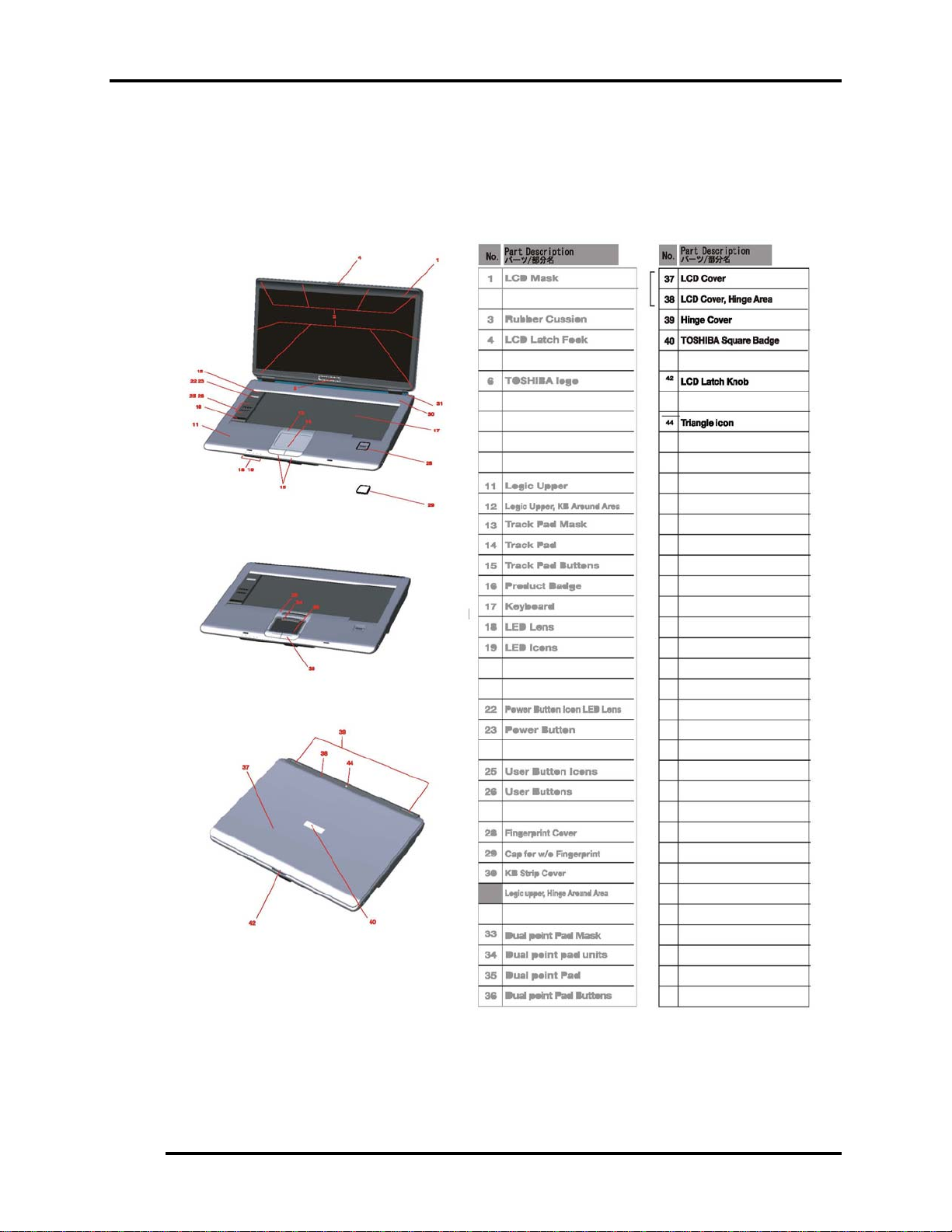
Figure 1- 1 id Parts description placement..............................................................................6
Figure 1- 2 The computer Block diagram ................................................................................7
Figure 1- 3 System Board configuration.................................................................................8
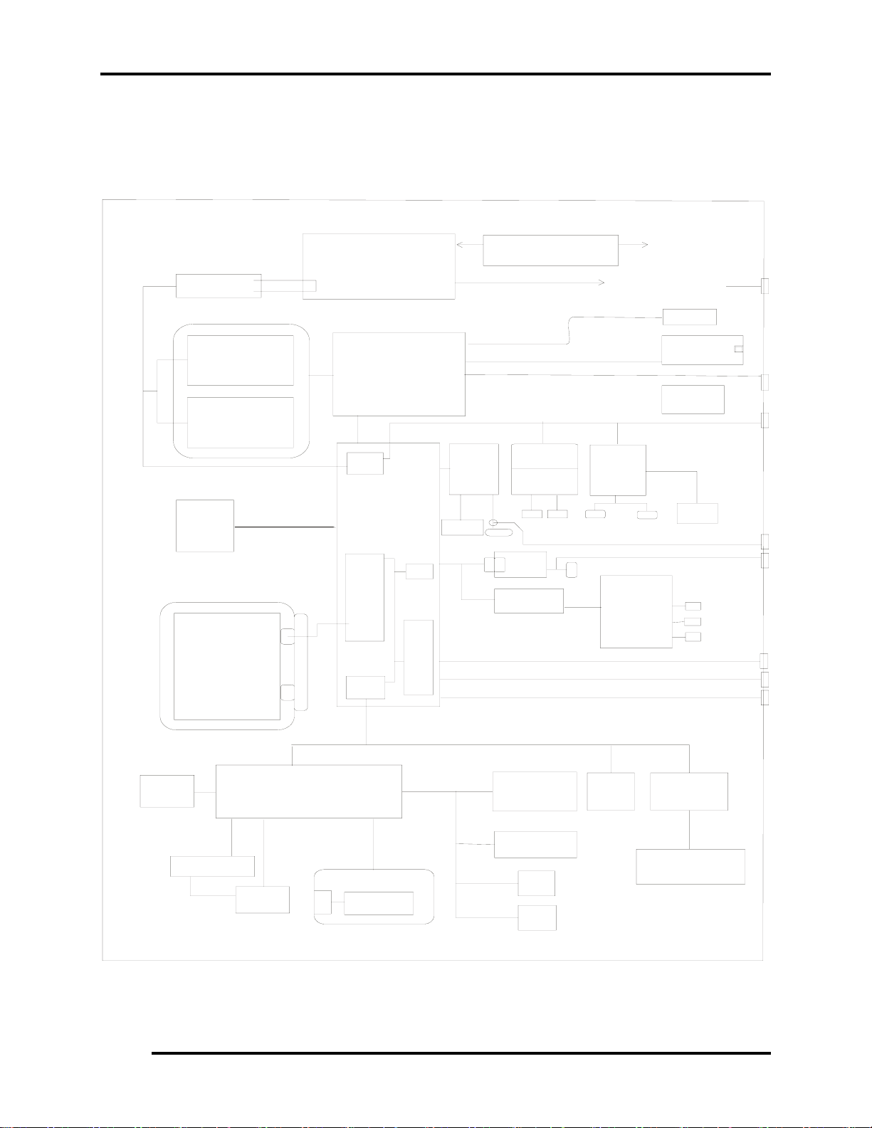
Figure 1- 4 System unit block diagram ....................................................................................9
Figure 1- 5 2.5-inch HDD .....................................................................................................15
Figure 1- 6 DVD-ROM drive................................................................................................16
Tables
Table 1- 1 2.5-inch HDD specifications................................................................................15
Table 1- 2 DVD-ROM drive specifications ..........................................................................16
Table 1- 3 CD-RW/DVD-ROM drive specifications............................................................17
Table 1- 4 DVD Super Multi drive (+-R Double Layer) specifications ...............................18
Table 1- 5 Battery specifications...........................................................................................20
Table 1-6 Quick/normal charging time .................................................................................21
iv Satellite A100/A105 / TECRA A7 Maintenance Manual
Page 18

1.1 Features 1 Hardware Overview
1.1 Features
The Toshiba Satellite A100/A105 / TECRA A7 is a full size notebook PC based on the Intel
Pentinm M (Dothan) and Celeron M processor, providing high-speed processing capabilities and
advanced features. The computer employs a Lithium Ion battery that allows it to be batteryoperated for a longer period of time. The display uses 15.4-inch WXGA and WSXGA+ LCD
panel, at a resolution of 1280 by 800 pixels (WXGA) and 1680 by 1050 pixels (WSXGA+), The
uPGA socket supports BTO/CTO for the CPU so that the system can be designed to suit your
needs.
The computer has the following features.
Processor
The CPU is the Intel Yonah Processor and Intel Yonah based Celeron M.
Intel Yonah Processor (667MHz)
T2300(1.66G)/T2400(1.83G)/T2500(2G)/T2600(2.16G)/T2700(2.33G)
/T1300(1.66G)/T1400(1.83G) Hz
Intel Yonah based Celeron M Processor (533MHz)
410/420/430
Host bridge system controller
System controller: Intel 945GM/945PM/940GML
Memory
The computer has two SO DIMMs slot comes standard with DDRII 4200 module. It
supports PC2-4200 and uses SO DIMMs (DDRII SDRAM) driven at 1.8 V, accepting
BTO/CTO for your memory requirements. It can incorporate up to 4 GB of main
memory.
using the following sizes of memory modules:
y 256 MB (16M×16×8P)/533/667 MHZ
y 512 MB (32M×16×8P)/533/667 MHZ
y 1024 MB (64Mx16x8P)/533/667 MHZ
Satellite A100/A105 / TECRA A7 Maintenance Manual 1
Page 19

1 Hardware Overview 1.1 Features
Hard Disk Drive (HDD)
The computer accommodates one 2.5-inch HDD with any of the following storage
capacities:
y 40 GB (9.5 mm thick) SATA (5,400rpm)
y 60 GB (9.5 mm thick) SATA (5,400rpm/7200rpm)
y 80 GB (9.5 mm thick) SATA (5,400rpm/7200rpm)
y 100 GB (9.5 mm thick) SATA (5,400rpm/7200rpm)
y 120 GB (9.5 mm thick) SATA (5400rpm)
ODD
The ODD can accommodate a DVD-ROM, CD-RW/DVD ROM,
DVD Super Multi (+-R Double Layer)drives.
Display
The LCD displays available come in the following four sizes:
y 15.4” WXGA-Non CSV/15.4” WXGA-CSV/15.4” WXGA-CSV(200 NITs High
brightness) /15.4” WXGA-HHCSV(490 NITs High brightness) color display,
resolution 1280×800,262,144 colors with dithering.
y
Keyboard
The keyboard has 29 kinds countries key.
Batteries
The computer has a removable 6/9/12 Cell Lithium Ion battery pack and an internal RTC
battery (rechargeable).
Universal Serial Bus (USB) ports
The computer has four USB 2.0 ports, It is supported to daisy-chain a maximum of 127
USB devices. The serial data transfer rate is 480 Mbps or 12 Mbps and 1.5 Mbps These
ports support PnP installation and hot plugging.
2 Satellite A100/A105 / TECRA A7 Maintenance Manual
Page 20

1.1 Features 1 Hardware Overview
External monitor port
A 15-pin external monitor port is provided, through which the computer automatically
recognizes an external VESA DDC 2B compatible monitor.
PC Card slot
A PC Card slot is provided to hold PC Card Standard Type II (5.0 mm) card, capable of
using a variety of PC Cards including 16-bit Multiple Function PC Cards and 32-bit
CardBus cards.
PC card HDD boot does Not be supported.
SD/MS/MS Pro/MMC/XD Card slot(BTO)
This slot is for your memory card requirements to provide memory card read on your
computer
Toshiba Pointing Device(BTO)
Toshiba Pointing Device has one kind of Synaptice TouchPad with two button and
One kind of Dual mode Pad for BTO .
Sound system
The ALC861 integrated audio controller supports multimedia. The sound system
contains the following:
y Stereo speakers
y Headphone jack
y Internal microphone
y External microphone jack
LAN
The internal LAN board supports 10/100 Mbit and Giga-bit for BTO, enabling
connection to a LAN at up to 1GMbps. It also supports Wake-up On LAN From
S3/S4/S5 and PXE boot support. The LAN board has the RJ45 jack to directly
accommodate a LAN cable.
Satellite A100/A105 / TECRA A7 Maintenance Manual 3
Page 21

1 Hardware Overview 1.1 Features
Wireless LAN
The internal Mini Card slot supports IEEE802.11a/g(11ch)/ IEEE802.11g(11ch)/
IEEE802.11a/g(13ch)/ IEEE802.11g(13ch)/IEEE802.11a/g(14ch)/ IEEE802.11g(14ch)
card. The Antenna has three wires dual band antenna support with Blue tooth for BTO.
Internal Modem
The computer contains a MDC, enabling data and fax communication. It supports ITUT V.90 (for rest countries )/V.92(America, Canada,UK,Germany,France) The transfer
rates are 56 Kbps for data reception, 33.6 Kbps for data transmission, and 14,400 bps for
fax transmission. Note, however, that the actual speed depends on the line quality. The
RJ11 modem jack is used to accommodate a telephone line.
IEEE 1394(BTO)
The IEEE 1394 serial data transfer rate is 400 Mbps, These port support hot plugging.
Finger Print(BTO)
This product has a fingerprint utility installed for the purpose of enrolling and
recognizing fingerprints. By enrolling the ID and password to the fingerprint authentication device, it is no longer necessary to input the password from the keyboard. Just by
swiping the finger against the fingerprint sensor.
TPM 1.2
The Trusted Platform Module (TPM) is an integrated circuit and software platform that
provides computer manufacturers with the core components of a subsystem used to
assure authenticity, integrity and confidentiality in e-commerce transactions and Internet
communications.
CD Key(BTO)
The CD Key supports to play Audio CD directly.
PCI Express Slot(BTO)
4 Satellite A100/A105 / TECRA A7 Maintenance Manual
Page 22

1.1 Features 1 Hardware Overview
The ICH7 provides PCI Express root ports which are compliant to the PCI Express Base
Specification ,Revision 1.0a.The Root Port supports 2.5Gb/s bandwidth in each direction
(5 Gb/s concurrent) and two virtual channels for full isochronous data support.
Parallel Port(BTO)
The Parallel Port is optional integrated device. to supported connect a printer or
another parallel device. The port is IEEE-1284 compliant and supports Extended
Capabilities Port (ECP).
Fast Serial Infrared (FIR) communications port(BTO)
The FIR Port is optional integrated device. It provided an IrDA 1.1 compatible FIR port ,
enabling wireless communication at a high speed of 1.15 or 4 Mbps.
Satellite A100/A105 / TECRA A7 Maintenance Manual 5
Page 23
1 Hardware Overview 1.1 Features
Figures 1-1/1-2/1-3 and 1-4 show the computer and its system unit configuration,
respectively.
Figure 1- 1 id Parts description placement
6 Satellite A100/A105 / TECRA A7 Maintenance Manual
Page 24

1.1 Features 1 Hardware Overview
USB 2
USB 1
USB0
CON N A
CON N B
PORT REPLICATOR
BA TTERY
CON N C
HDD
ODD
S-video
LCM
CRT
USB 3
CON N D
USB5
USB4
Bluetooth
MDC/ Modem
Modul e 56K
SATA
Pri mar y_ I DE
USB6
FINGER PRINT
USB7
Express Card
3.3V, AZALI A
AZALIA
DO CKING
Yonah
(uFCPGA)
FSB, 533/ 667 MHz
Calistoga
945GM /PM
1466 uFCBGA
DMIx4
ICH7-M
652 BGA
3.3V, LPC_Interface,33MHz
ICS9LP306
Clock generator
1.8V, DDR2 I nt er f ace, 533/ 667 MHz
1.8V, DDR2 I nt er f ac e, 533/667 MHz
PCI_EXPRESS
INTEL
10/100 82562GZ
1G 82573 E( AT M)
82573L( w/o ATM)
RJ45
MINI CA RD
Wireless LAN
ANT
DDR2 _SODIMM0
3.3V, PCI_ I nt er f ac e,33MHz
EXPRESS CARD
ANT
DDR2_SODIMM1
CA RD B US
TI PCI7412 4512_/
(CO-LAYOUT)
Card b us
SL OT A
Card reader
CO NN
1394
CONN
System Charger &
DC/DC System p o wer
(IMVP-6
VR)
RJ11
MIC
JACK
HP
JACK
SPEAKER
SMSC
KBC1100
BIOS
FLASH ROM
3- AXI S SENSOR
SERI AL PORT
Figure 1- 2 The computer Block diagram
FIR
CIR
TPM 1.2
SMSC
SIO 1036
PARALLEL PORT
Satellite A100/A105 / TECRA A7 Maintenance Manual 7
Page 25
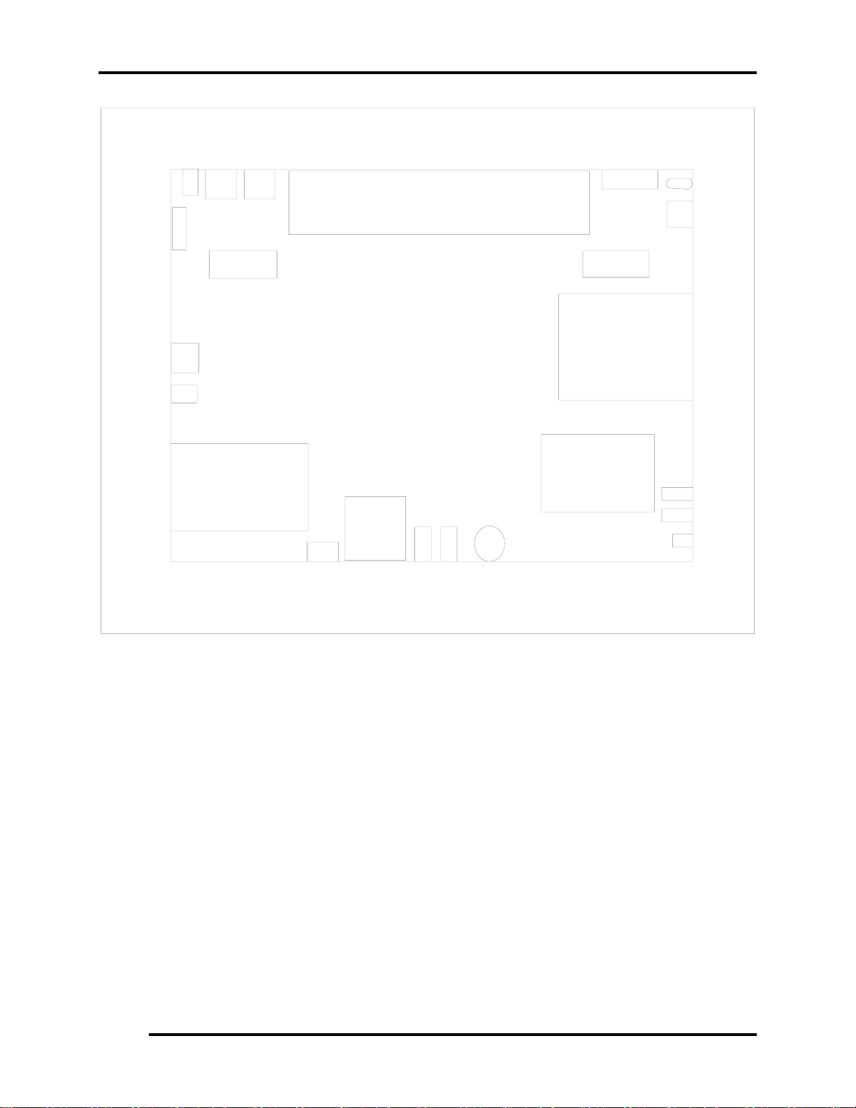
1.1 Features 1 Hardware Overview
Rj 4 5
Par al l el
Ken s i ngt on
Rj 1 1
RGB
DC- I N
USB* 2
Battery
S- Vi deo
1394
Spe ak e r
PC Car d* 1
Express Car d *1
Figure 1- 3 System Board configuration
FI R/ CI R
5 i n 1
Car d
Reader
Vol ume
Mi c r ophone
Headphone
Spe ak e r
ODD
HDD
USB* 2
Ki l l SW
Satellite A100/A105 / TECRA A7 Maintenance Manual 8
Page 26
1.2 System Unit Components 1 Hardware Overview
1.2 System Unit Components
Figure 1-4 is a block diagram of the system unit.
Max 6657
Themal Sensor
Pc4200 DDRI I
533/ 667 Mhz
Expans i on
Me mo r y
256/ 512/ 1024
Expans i on
Me mo r y
256/ 512/ 1024
I nt - HDD
SATA
40- 120GB
9. 5mm
DVD- ROM
DVD- CD/ RW COMBO
DVD Super Mul t i
(+-R Double l ayer)
CPU : Intel
Yonah
1.66G......2.33GHZ
uPGA
Intel
945GM/ PM
940GML
No r t h Br i dg e
DMI
SM Bus
Cont .
ICH7-M
SATA
Sout h
Br i dge
IDE
Cont .
PCI - PC
Br i dge
Ac97
USB
Cont .
( 02)
LAN
Cont .
10/ 100
82562GZ
1G
82573E
EEPRO M
Cl o c k Ge ne r a t o r
( I CS9LP306)
CPU V I D
Mini
PCI Sl o t
802. 11g, a / g
Wireless
Lan
Rj 45
CODEC
ALC 86 1
MDC
Modem
Ant enna
PCMCI A
Rj 11
I SL6218
LVDS
CARD BUS
Controller
TI PCI 7412
_
/
PCI 4512
TPA6011
5i n1
Car d
Read er
DC
S- Vi deo
LCD 15. 4"
VRAM
1394
CNNx1
Speaker
MI C
Headphone
CRT
USB
USB
USB
Internal LPC
Fl ash
ROM
Stick point
K/ B
EC/ KBC
( KBC1100)
KPA AC
1269A
I2C
Ma i n B a t t e r y
EEPRO M
3- AXI S
SENSOR
SERI AL
PO R T
FI R
TPM
1. 2
SMSC
SI O 1036
PARALLEL
PO R T
CI R
Figure 1- 4 System unit block diagram
Satellite A100/A105 / TECRA A7 Maintenance Manual 9
Page 27

1 Hardware Overview 1.2 System Unit Components
The system unit of the computer consists of the following components:
Processor: Intel Yonah Processor and Yonah Based Celeron M
y Intel Yonah Processor (667MHz)
− Core speed: 1.66/1.83/2.0/2.16/2.33 GHz
− System bus: 667 MHz
− On-die level 2 cache 2 MB
− Advanced Power Management features including Enhanced
Intel ® SpeedStep ® technology
y Yonah Based Celeron-M (533MHz)
− Core speed: TBD
− System bus: 533 MHz
− On-die level 2 cache 1 MB
Memory
Two expansion memory slots were provided, They can hold 256/512/1024MB expansion
memory modules available as options to grow up to 4.0 GB.
y PC2-4200 /533/667MHz DDRII SDRAM supported
y 256/512/1024MB modules supported
− 256 MB (16M x 16 x 8P)
− 512 MB (32M x 16 x 8P)
− 1024 MB (64M x 8 x 16P)
y 1.8 volt operation
y No parity bit
y 64-bit data transfer
10 Satellite A100/A105 / TECRA A7 Maintenance Manual
Page 28

1.2 System Unit Components 1 Hardware Overview
BIOS ROM (flash EEPROM)
y 8Mb x 1 chip (1024KB flash parts)
− 40Kb used for EC BIOS
− 35Kb used for PNP
− 3Kb used for display
− 15Kb used for logo
− 16Kb used for setup
− 10Kb used for setup nodes
− 1Kb used for decompress code
− 1Kb used for boot block
− 2Kb used for TPM
− 64Kb used for
− 23Kb used for miser
− 237Kb used for VGA BIOS
− 42Kb used for PXE
− 14Kb used for string
− 47Kb used for ROMEXEC
− 133Kb used for BIOS code
− 6Kb used for mini loader
System controllers
y North Bridge: Intel 945 GM/PM/940GML
− CPU interface and control
− System Memory Support
− PCI Express* Graphics (PEG) Interface
− Integrated Display Interface Support
− Internal Graphics Features
− Direct Media Interface (DMI)
− Power Management
− Serial ATA Interface
− ICH7 Audio Control
− SMBus 2.0/SMLink Interface
y South Bridge: ICH7-M
− Direct Media Interface (DMI)
− PCI Express* Interface
− Serial ATA (SATA) Controller
Satellite A100/A105 / TECRA A7 Maintenance Manual 11
Page 29

1 Hardware Overview 1.2 System Unit Components
− Advanced Host Controller Interface (AHCI)
− PCI Interface
− IDE Interface
− Low Pin Count (LPC) Interface
− Compatibility Modules
− Advanced Programmable Interrupt Controller (APIC)
− Universal Serial Bus (USB) Controller
− Lan Controller
− Alert Standard Format (ASF) Management Controller
− RTC
− GPIO
− Enhanced Power Management
− Manageability
− System Management Bus (SMBus 2.0)
− Intel High Definition Audio Controller
− AC ’97 2.3 Controller
PC Card controller
y TI_PCI7412
− CardBus/PC Card controller
− 16-bit PCMCIA and 32-bit CardBus.
− SD/MS/MS Pro/MMC/XD Card controller
− IEEE 1394 Controller
Audio Controller
The ALC861 integrated audio controller supports multimedia. The sound system feature
contains the following:
y 4 Stereo DACs support 16/20/24-bit PCM format for 7.1 channel audio solution.
y 1 stereo ADCs support 16-bit PCM forma.t
y Front/Surround /Cen/Lfe/Side-Surround DACs support independent 48KHz/96KHz
sample rate.
y ADC support 48K/96K sample rate.
y FRONT(port-D),LINE2(port-E)and MIC2(port-F) are stereo input and output re-tasking.
y High quality differential CD input.
y 2 jack detection pins each supports up to 4 jacks can be detected.
y Support 48KHz/96KHz of S/PDIF output.
y Supports analog PCBEEP input.
y Integrates digital BEEP generator.
12 Satellite A100/A105 / TECRA A7 Maintenance Manual
Page 30

1.2 System Unit Components 1 Hardware Overview
y Power support : Digital : 3.3V ; Analog : 5.0V
y 48-ping LQFP package.
KBC/EC (Keyboard Controller/Embedded Controller)
A single KBC 1100L chip is used to serve as KBC/ EC and Super IO.
y KBC
− Scan controller function
− Interface controller function
y EC
− Power supply sequence control
− Overheat shutdown support
− LED control
− Beep control
− Device ON/OFF
− Cooling fan speed control
− Universal I/O port
− Battery capacity check
− Flash memory reprogramming function
− EC access interface
− I2C communication control
−
Battery EE PROM
y 24C02 equivalent (128 words x 16 bits, I2C interface) integrated in the battery pack
− Storing records of battery use
Clock Generator
y ICS9LP306
− Generating the clock signal required for the system
Modem Controller
y Built-in MDC card with askey
y Functions of the modem controller:
− Digital signal conductor protection
− Ring wake-up support
− Communication codes supported:
Satellite A100/A105 / TECRA A7 Maintenance Manual 13
Page 31

1 Hardware Overview 1.2 System Unit Components
For data communication:
V.90(China)/V.92 data rates: 28kbps/56kbps
V.34 Extended rates: 33.6K/2400/V.32 turbo, V.32bits,and fallbacks
For fax:
V.34,V.17,V.29 V.27 and V.21 Channel 2
V.253 Class 1 fax
-AC97 interface
LAN controller
y 82562GZ
− IEEE 802.3 10BASE-T/100BASE-TX compliant physical
layer interface
− IEEE 802.3u Auto-Negotiation support
− Digital Adaptive Equalization control
− 10BASE-T auto-polarity correction
− LAN Connect interface
− Automatic detection of “unplugged mode”
− Remote boot(PXE 2.1)
− Smart power down when link is not detected
y 82573E
− PCIe Power Management
− Peak bandwidth 2 gigabytes/second per direction
− Digital Adaptive Equalization control
− Optimized transmit and receive queues
− On-board microcontroller
− SNMP and RMON statistic counters
− SDG 3.0, WfM 3.0, and PC2001 compliance
− Wake on LAN support
Wireless LAN controller
y Support following 2 kinds of mini PCI wireless LAN cards.
− IEEE 802.11g
− IEEE 802.11a/g
y Transfer Rate
− IEEE 802.11a/g: Standard 54M bps
− IEEE 802.11g: Standard 54M bps
y Frequency Channel
− IEEE802.11a/g: 5.4GHz
− IEEE802.11g: 2.4GHz
14 Satellite A100/A105 / TECRA A7 Maintenance Manual
Page 32

1.3 2.5-inch HDD 1 Hardware Overview
1.3 2.5-inch HDD
The computer contains an extremely low-profile and lightweight, high-performance HDD.
The HDD incorporates a 2.5-inch magnetic disk and mini-Winchester type magnetic heads.
Storage capacities supported are 40,60,80,100/120 GB.
The HDD interface conforming to Serial ATA (for 40/60/80/100/120 GB).
The HDD is shown in Figure 1-5 and some of its specifications are listed in Table 1-1.
Figure 1- 5 2.5-inch HDD
Table 1- 1 2.5-inch HDD specifications
rpm
Specifications
5400
rpm
7200
rpm
5400
rpm
7200
rpm
5400 rpm
Item
Capacity (GB) 40GB 60GB 80GB 100GB 120GB
Rotational
speed
(RPM)
User data
sectors
Bytes/sector 512 512 512 512 512
5400 rpm
78,140,160 117,210,240 156,301,488 195,371,568 234,442,648
5400
rpm
7200
Satellite A100/A105 / TECRA A7 Maintenance Manual 15
Page 33

1.6 DVD Super Multi (+-R Double Layer) 1 Hardware Overview
1.4 DVD-ROM Drive
The DVD-ROM drive accepts 12-cm (4.72-inch) and 8-cm (3.15-inch) discs. The drive
provides high-speed data transfer, playing back a DVD at up to 8x speed and reading up to
10,820 Kbytes per second from DVD-ROM and 3,600 Kbytes per second from CD-ROM.
The DVD-ROM drive is shown in Figure 1-6 and its specifications are listed in Table 1-2.
Figure 1- 6 DVD-ROM drive
Table 1- 2 DVD-ROM drive specifications
Item DVD-ROM
Data transfer rate (Mbytes/s) 33.3 (U-DMA transfer mode 2)
16.7 (PIO mode 4, Multiword DMA mode 2)
Access time (ms)
100ms
Average random access
Data buffer size (Kbytes) 512KB
Formats supported DVD-R/W(Read only), DVD-R (Read only),DVD-
RAM ,
CD-ROM, CD-R,CD-DA,CD-I,CD(Photo-CD,CD-
EXTRA,CD-R,CD-RW,Portiolio)
CD-R (Read only), CD-RW (Read only)
Satellite A100/A105 / TECRA A7 Maintenance Manual 16
Page 34

1.5 CD-RW/DVD-ROM Drive 1 Hardware Overview
1.5 CD-RW/DVD-ROM Drive
The CD-RW/DVD-ROM drive accepts 12-cm (4.72-inch) and 8-cm (3.15-inch) discs. At
maximum, the drive can play back a DVD at 8x speed, read CD-ROM at 24x speed, and
write CD-R at 24x speed and HS CD-RW at 10x speed and US CD-RW at 24x speed and
CD-RW at 4x speed.
The specifications of the CD-RW/DVD-ROM drive are listed in Table 1-3.
Table 1- 3 CD-RW/DVD-ROM drive specifications
Item DVD-ROM mode CD-RW mode
33.3 (U-DMA transfer mode 2) Data transfer rate
(Mbytes/s)
Access time (ms)
Average random
access
Data buffer size
(Mbytes)
Formats supported
16.7 (PIO mode 4, Multiword DMA mode 2)
150 ms 130 ms
2MB
DVD:
DVD-ROM,DVD-R,DVD-RAM
CD:
CD-DA,CD+(E)G,CD-MIDI,CD-TEXT,CD-ROM,CD-ROM XA,MIXED
MODE CD,CD-I,CD-I Bridge(Photo CD,Video CD),Muitisession
CD(Photo CD,CD-EXTRA,Portfolio,CD-R,CD-RW),CD-R,CD-RW
Satellite A100/A105 / TECRA A7 Maintenance Manual 17
Page 35

1.6 DVD Super Multi (+-R Double Layer) 1 Hardware Overview
1.6 DVD Super Multi (+-R Double Layer)
The DVD Super Multi drive accepts 12-cm (4.72-inch) and 8-cm (3.15-inch) discs. At
maximum, the drive can play back a DVD at 8x speed, read CD-ROM at 24x speed, and
write CD-R at 24x speed and CD-RW at 4x speed and US CD-RW at 16x speed and High
speed CD-RW at 10x speed and DVD-R at 8x speed and DVD-RW at 6x speed and DVD+R
at 8x speed and DVD+R (Double Layer) at 4x speed and DVD-R (Double Layer) at 4x speed
and DVD+RW at 8x speed and DVD-RAM at 5x speed.
The specifications of the DVD Super Multi (+-R Double Layer) drive are listed in Table 1-4.
Table 1- 4 DVD Super Multi drive (+-R Double Layer) specifications
Item DVD-ROM mode CD-ROM mode
33.3 (U-DMA transfer mode 2) Data transfer rate
(Mbytes/s)
16.6 (PIO mode 4, Multiword DMA mode 2)
Access time (ms)
Average random
access
Data buffer size
(Mbytes)
Formats supported
130 130
2MB
DVD:
DVD-VIDEO,DVD-ROM,DVD-R,DVD-RW,DVD-RAM,
DVD+R,DVD+-R(Double Layer),DVD+RW.
CD:
CD-DA,CD-ROM, CD-R,CD-RW,CD-ROMXA,
PhotoCD(muitiSession),Video CD,CD-Extra(CD+),CD-Text
Satellite A100/A105 / TECRA A7 Maintenance Manual 18
Page 36

1.7 Power Supply 1 Hardware Overview
1.7 Power Supply
The power supply unit provides many different voltages for the system board and performs the
following functions:
1. Power input monitor
y Checks whether the DC power supply (AC adapter) is connected to the computer.
y Checks whether the battery pack is connected to the computer.
y Monitors the DC power supply input voltage (AC Adapter output voltage).
2. Power supply's internal control
y Turns on and off the battery pack charging power supply.
y Issues a charging current instruction to the PWM control IC of the battery pack charging
power supply.
y Controls the supply of DC power supply input (AC Adapter output) to the power supply
unit.
y Controls the supply of power to the system block (load/logic circuit side).
y Controls forced shutdown if the power supply malfunctions.
3. Logic circuit control
y Instructs the gate array to enable/disable tuning the power on.
y Controls power-on/off operation.
4. Status display
y Turns on the Power LED (in Blue or Green or AMBER).
y Battery indicator (in Blue or Green or AMBER or AMBER Flash).
5. External interface
y Performs communication through the I2C bus (via the internal EC/KBC).
y Transfers the power supply operation mode.
6. Output monitor
y Monitors the voltage output to the system block (load/logic circuit side).
y Monitors the voltage, over voltage, input/output current of the battery pack.
y Monitors the internal temperature of the battery pack.
y Monitors the supply voltage from the AC adapter.
Satellite A100/A105 / TECRA A7 Maintenance Manual 19
Page 37

1 Hardware Overview 1.8 Batteries
1.8 Batteries
The computer has the following three types of batteries:
Main battery pack
Real time clock (RTC) battery
Table 1-5 lists the specifications of these batteries.
Table 1- 5 Battery specifications
Battery name Material Output voltage Capacity
6 Cell Lithium Ion 10.8 V 4000 mAh
Main battery pack
9 Cell Lithium Ion 10.8 V 6000 mAh
12 Cell Lithium Ion 10.8 V 8600 mAh
RTC battery Lithium Ion 3.0 V 14 mAh
1.1.1 Main Battery
The main battery pack serves as the computer's main power source when the AC adapter
is not attached. The main battery maintains the state of the computer so that it can
resume it.
1.1.2 Battery Charging Control
Battery charging is controlled by LPC 47N249. When the AC adapter and battery pack
are attached to the computer, the LPC 47N249 controls the charge on/off state and
detects a full charge.
Battery Charge
When the AC adapter is attached, the battery is charged by off-state charge when the
system is powered off or by on-state charge when it is powered on.
20 Satellite A100/A105 / TECRA A7 Maintenance Manual
Page 38
1.8 Batteries 1 Hardware Overview
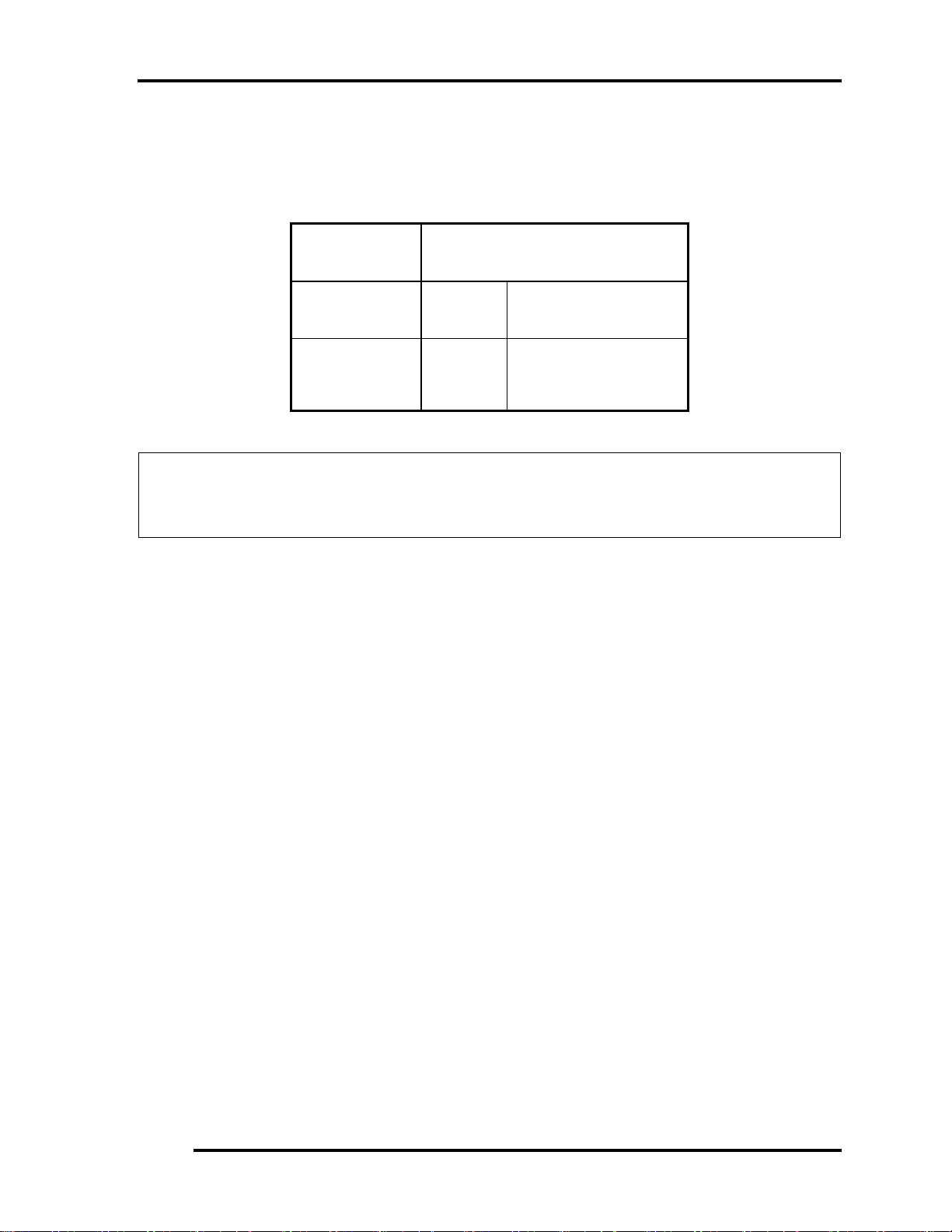
Table 1-6 Quick/normal charging time
State Charge time
Off-state charge
On-state charge
6/9/12
Cell
6/9/12
Cell
About 4 hours max
About 4~10 hours max
NOTE: The time required for normal charge depends on the power consumption by the
system. Using the fluorescent lamp and frequently accessing the disk consume much
power and lengthen the charge time.
Any of the following cases stops battery charge:
1. The battery becomes fully charged.
2. The AC adapter or battery pack is removed.
3. The battery or AC adapter voltage is abnormal.
Detection of full charge
A full charge is detected only when the battery is being charged by quick or normal
charge. A full charge is detected when either of the following conditions is met:
1. The current in the battery charging circuit drops below the predetermined
value.
2. The charging time exceeds the fixed limit.
1.1.3 RTC Battery
The RTC battery provides power to keep the current date, time and other system information
in memory while the computer is turned off.
Satellite A100/A105 / Satellite Pro A100 / EQUIUM A100 Maintenance Manual 21
Page 39

2 Troubleshooting
2
Chapter 2 Troubleshooting
2-i Satellite A100/A105 / TECRA A7 Maintenance Manual
Page 40

2 Troubleshooting
Chapter 2 Contents
2.1 Outline....................................................................................................................2-1
2.2 Basic Flowchart......................................................................................................2-2
2.3 Power Supply .........................................................................................................2-6
Procedure 1 Power Icon Check.......................................................................2-6
Procedure 2 Connection Check....................................................................... 2-8
Procedure 3 Replacement Check....................................................................2-8
2.4 System Board .........................................................................................................2-9
Procedure 3 Replacement Check.................................................................2-11
2.5 2.5-inch HDD....................................................................................................... 2-12
Procedure 1 Message Check......................................................................... 2-12
Procedure 2 Partition Check ..........................................................................2-12
Procedure 3Format Check..............................................................................2-14
Procedure 4Test Program Check ...................................................................2-15
Procedure 5Connector Check and Replacement Check.................................2-16
2.6 Keyboard.............................................................................................................. 2-17
Procedure 1 Test Program Check ..................................................................2-17
Procedure 2 Connector Check and Replacement Check................................2-17
2.7 Display ................................................................................................................. 2-18
Procedure 1External Monitor Check .............................................................2-18
Procedure 2Test Program Check ...................................................................2-18
Procedure 3Connector Check and Replacement Check.................................2-18
2.8 ODD (Optical Disk Drive)................................................................................... 2-20
Procedure 1ODD Cleaning Check.................................................................2-20
Procedure 2Test Program Check ...................................................................2-20
Procedure 3Connector Check and Replacement Check.................................2-20
2.9 LAN...................................................................................................................... 2-22
Procedure 1Test Program Check ...................................................................2-22
Procedure 2Connector Check and Replacement Check.................................2-22
2.10 SD/MS/MS pro/MMC/XD Card(Optional) .........................................................2-23
Procedure 1Test Program Check ...................................................................2-23
2-ii Satellite A100/A105 / TECRA A7 Maintenance Manual
Page 41

2 Troubleshooting
Procedure 2Connector Check ........................................................................2-23
2.11 Finger Print(Optional).......................................................................................... 2-24
Procedure 1Test Program Check ...................................................................2-24
Procedure 2Connector Check ........................................................................2-24
2.12 3D Sensor.............................................................................................................2-25
Procedure 1Test Program Check ...................................................................2-25
Procedure 2Replacement Check....................................................................2-25
2.13 Parallel Port(Optional) .........................................................................................2-26
Procedure 1Test Program Check ...................................................................2-26
Procedure 2Connector Check ........................................................................2-26
2.14 Audio Test............................................................................................................ 2-27
Procedure 1 Test Program Check ..................................................................2-27
Procedure 2 Connector Check and Replacement Check................................2-27
2.15 IEEE 1394 Test ....................................................................................................2-28
Procedure 1Test Program Check ...................................................................2-28
Procedure 2Connector Check ........................................................................2-28
2.16 Cooling Module....................................................................................................2-29
Procedure 1Test Program Check ...................................................................2-29
Procedure 2Connector Check and Replacement Check.................................2-29
Satellite A100/A105 / TECRA A7 Maintenance Manual 2-iii
Page 42

2 Troubleshooting
Figures
Figure 2-1 Basic flowchart ..............................................................................................2-3
Tables
Table 2-1 HDD error code and status........................................................................... 2-15
2-iv Satellite A100/A105 / TECRA A7 Maintenance Manual
Page 43

2.1 Outline 2 Troubleshooting
2.1 Outline
This chapter describes the fault diagnosis procedures for field replaceable units (FRUs) in the
computer.
The FRUs covered here are as follows:
1. System board 2. 2.5-inch HDD 3. Keyboard
4. Display 5. ODD drive 6. LAN
7. SD/MS/MS pro/MMC/XD 8. Finger Print
9. Speaker 9. IEEE 1394 10. Cooling module
See Chapter 4 for the procedures to replace FRUs and Chapter 3 for the procedures to use test
programs
The following tools are required to perform the diagnostic procedures:
1. Diagnostics (maintenance test program) disk
2. Phillips screwdrivers (2 mm, 2.5 mm)
3. Cleaning disk kit (for ODD drive cleaning)
4. Bootable CD
5. PC Card loopback connector
6. Multimeter
7. External monitor
8. Headphone
9. Microphone
10. A-BEX TEST DVD
11. Music CD
12. DVD TSD-1 (TOSHIBA EMI DVD Test Media)
Satellite A100/A105 / TECRA A7 Maintenance Manual 2-1
Page 44

2 Troubleshooting 2.2 Basic Flowchart
2.2 Basic Flowchart
The basic flowchart in Figure 2-1 serves as a guide for identifying a possibly faulty FRU.
Before going through the diagnostic flowchart steps, verify the following:
Ask the user if a password has been registered and, if so, ask him or her to enter the
password. If the user has forgotten the system password, use a jump wire to make a
short circuit on M/B C88 , then turn the computer power on. When booted, the
computer overrides password protection and automatically erases the current
password.
Make sure the Windows® XP Home Edition has been installed on the HDD. Any
other operating system can cause the computer to malfunction.
Make sure any piece of optional equipment has been installed.
2-2 Satellite A100/A105 / TECRA A7 Maintenance Manual
Page 45

2.2 Basic Flowchart 2 Troubleshooting
p
p
p
p
p
N
N
NoN
N
N
Star
t
Connect the AC Adapter
DC IN LED on ??
Follow the power supply diagnostic
rocedure in Section 2.3
BATTERY LED on ??
Yes
o
Follow the power supply diagnostic
rocedure in Section 2.3
Turn the power on.
Yes
Any error message displayed ??
o
Yes
Follow the system board diagnostic
rocedure in Section 2.4
Message "In Touch with
Tomorrow Toshiba" displayed
o
Follow the display diagnostic
rocedure in Section 2.7
"Password=" displayed ??
Yes
Yes
See the previous page to
delete the password.
o
OS started ??
o
Yes
1
Follow the HDD diagnostic
rocedure in Section 2.5
Figure 2-1 Basic flowchart(1/2)
Satellite A100/A105 / TECRA A7 Maintenance Manual 2-3
Page 46

2 Troubleshooting 2.2 Basic Flowchart
N
r
NoN
N
1
Keyboard works well ??
Insert Bootable CD into ODD
Diagnostic Program
Loaded ??
Yes
Perform each test with the
diagnostic program.
Any error detected by the
diagnostic program ??
o
Perform the continuous test to check if the
error is intermittent.
Any error detected by the
diagnostic program ??
o
The system is normal.
END
Figure 2-1 Basic flowchart (2/2)
o
Yes
Yes
Follow the keyboard diagnostic
procedure in Section 2.6
Follow the ODD diagnostic
procedure in Section 2.8
Identify the test resulting in the erro
and perform the appropriate
diagnostic procedures
Identify the test resulting in the
error and perform the appropriate
diagnostic procedures
2-4 Satellite A100/A105 / TECRA A7 Maintenance Manual
Page 47

2.2 Basic Flowchart 2 Troubleshooting
If the diagnostic program cannot detect an error, the error may be intermittent. Run the
continuous test program repeatedly to isolate the problem. Check the log utilities function to
confirm which diagnostic test detected the error, then perform the appropriate
troubleshooting procedures as follows:
1. If an error is detected by the System test, Memory test, Async test, Printer test,
Sound test, or Real Timer test, follow the system board troubleshooting procedures in
Section 2.4.
2. If an error is detected by the Hard Disk test, follow the HDD troubleshooting
procedures in Section 2.5.
3. If an error is detected by the Keyboard test, follow the keyboard troubleshooting
procedures in Section 2.6.
4. If an error is detected by the Display test, follow the display troubleshooting
procedures in Section 2.7.
5. If an error is detected by the ODD test, follow the ODD troubleshooting procedures in
Section 2.8.
6. If an error is detected by the LAN test, follow the LAN troubleshooting procedures in
section 2.9.
7. If an error is detected by the SD Card test, follow the SD Card troubleshooting
procedures in section 2.10
8. If an error is detected by the Finger Print test, follow the Speaker troubleshooting
procedures in section 2.11.
9. If an error is detected by the 3D sensor test, follow the Speaker troubleshooting
procedures in section 2.12.
10. If an error is detected by the Parallel test, follow the Speaker troubleshooting
procedures in section 2.13.
11. If an error is detected by the Speaker test, follow the Speaker troubleshooting
procedures in section 2.14.
12. If an error is detected by the IEEE 1394 test, follow the IEEE 1394 troubleshooting
procedures in section 2.15.
13. If an error is detected by the Fan On/Off test, follow the cooling module
troubleshooting procedures in Section 2.16.
Satellite A100/A105 / TECRA A7 Maintenance Manual 2-5
Page 48
2 Troubleshooting 2.3 Power Supply
2.3 Power Supply
The power supply in the computer controls many functions and components. To check if the
power supply is defective or malfunctioning, follow the troubleshooting procedures below as
instructed.
Procedure 1 Power Icon Check
Procedure 2 Connection Check
Procedure 3 Replacement Check
Procedure 1 Power Icon Check
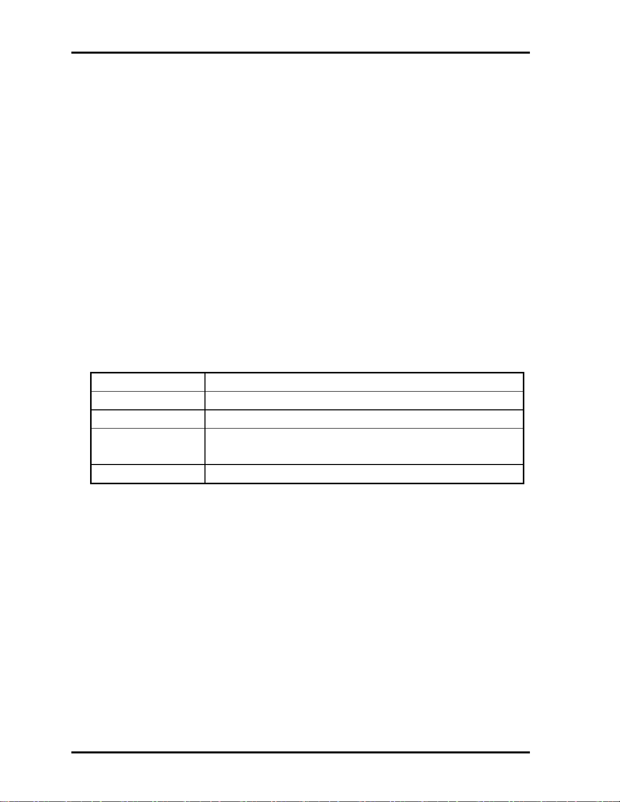
The following two power LEDs indicate the power supply status:
Battery LED
DC IN LED
The power supply controller displays the power supply status through the Battery and DC IN
LEDs as in the tables below.
Battery LED
Battery LED Power supply status
On in Amber Battery being charged
On in Green/Blue Battery fully charged, with AC adapter connected
Blinking in Amber
(at equal intervals)
Off Else
Battery low *1 while driving the computer
2-6 Satellite A100/A105 / TECRA A7 Maintenance Manual
Page 49

2.3 Power Supply 2 Troubleshooting
DC IN LED
DC IN LED Power supply status
On in Green/Blue DC power being supplied (from the AC adapter)
Off Battery damage and can’t charge during DC-in.
Off Else
If the DC IN LED off, follow the steps below:
1. Remove the battery pack and the AC adapter to shut off power supply to the
computer.
2. Attach the battery and AC adapter back again.
If the LED still off, follow the steps below:
Check 1 Make sure the DC IN LED goes on in Green or Blue . If it does not, go to
Procedure 2.
Check 2 Make sure the Battery LED goes on in Amber or Blue or Green . If it does
not, go to Procedure 3.
Satellite A100/A105 / TECRA A7 Maintenance Manual 2-7
Page 50

2 Troubleshooting 2.3 Power Supply
Procedure 2 Connection Check
Power is supplied to the system board as illustrated below:
AC
System board
adaptor
AC power cord
AC adaptor cord
Battery pack
Follow the steps below to check whether each connector has been connected correctly:
Check 1 Make sure the AC adaptor and AC power cord have been firmly plugged into
the DC IN 19V socket and wall outlet, respectively. When they have been
connected correctly, perform Check 2.
Check 2 Connect a new AC adaptor and AC power cord.
• If the DC IN LED does not go on, go to Procedure 3.
• If the battery LED does not go on, perform Check 3.
Check 3 Make sure the battery pack has been correctly installed in the computer. If the
battery LED does not go on while the battery pack has been installed correctly,
go to Procedure 3.
Procedure 3 Replacement Check
The system board, power supply board, or CPU may be faulty. Disassemble the computer
according to Chapter 4 and follow the steps below:
Check 1 Replace the power supply board with a new one. If the battery pack is still not
working properly, perform Check 2.
Check 2 Replace the system board with a new one. If the battery pack is still not
working properly, perform Check 3.
Check 3 Replace the CPU with a new one.
2-8 Satellite A100/A105 / TECRA A7 Maintenance Manual
Page 51

2.4 System Board 2 Troubleshooting
2.4 System Board
To check if the system board is defective or malfunctioning, follow the troubleshooting
procedures below as instructed.
Procedure 1 Message Check
Procedure 2 Test Program Check
Procedure 3 Replacement Check
Procedure 1 Message Check
When the power is turned on, the system performs the self-diagnostic Power On Self Test
(POST) embedded in the BIOS ROM. The POST tests and initializes each IC on the system
board.
If an error message appears on the display, perform Check 1.
If there is no error message, go to Procedure 2.
If MS-DOS or Windows XP Home Edition is loaded normally, go to Procedure 3.
Check 1 If the following error message is displayed on the screen, press the F1 key as
prompted. These errors occur when the system configuration preserved in the
RTC memory (generally called CMOS memory) does not match the actual
configuration or when the data is lost.
If you press the F1 key as prompted by the message, the TSETUP screen
appears to set the system configuration. If the error message appears
frequently when the power is turned on, replace the RTC battery. If any other
error message is displayed, perform Check 2.
*** Bad RTC battery ***
Check system. Then press [F1] key
Check 2 If the following error message is displayed on the screen, press any key as
prompted by the message.
The error message appears when either data stored in RAM to be resumed is
lost because the battery has been exhausted or the system board is faulty.
If any other error message displays, perform Check 3.
Check 3 Resume failure and press any key to continue.
Satellite A100/A105 / TECRA A7 Maintenance Manual 2-9
Page 52

2 Troubleshooting 2.4 System Board
2-10 Satellite A100/A105 / TECRA A7 Maintenance Manual
Page 53

2.4 System Board 2 Troubleshooting
Procedure 2 Test Program Check
The maintenance test program contains several programs for diagnosing the system board
and CPU. Execute the following test programs using the procedures described in Chapter 3.
1. System test
2. Memory test
3. Keyboard test
4. Display test
5. Hard Disk test
6. Mouse test
7. SD Card/Memory stick test
8. ODD test
9. Sound test
10. LAN test
If an error is detected during these tests, go to Procedure 3.
Procedure 3 Replacement Check
The system board, memory, or CPU may be defective. Disassemble the computer following
the steps described in Chapter 4 and replace the system board, memory module or CPU with
a new one.
Satellite A100/A105 / TECRA A7 Maintenance Manual 2-11
Page 54

2 Troubleshooting 2.5 2.5-inch HDD
2.5 2.5-inch HDD
To check if the 2.5-inch HDD is defective or malfunctioning, follow the troubleshooting
procedures below as instructed.
Procedure 1 Message Check
Procedure 2 Partition Check
Procedure 3 Format Check
Procedure 4 Test Program Check
Procedure 5 Connector Check and Replacement Check
CAUTION: The contents of the 2.5-inch HDD will be erased when the HDD 2.5-inch
HDD diagnostic test or formatting is executed. Save the required contents of the HDD to
floppy disks or other storage drive in advance.
Procedure 1 Message Check
When the computer's HDD does not function properly, some of the following error messages
may appear on the display. Follow the steps below to check the HDD.
Check 1 If either of the following messages appears, go to Procedure 2. If the following
messages do not appear, perform Check 3.
Insert system disk in drive
Press any key when ready .....
or
Non-System disk or disk error
Replace and press any key
Check 2 Check TSETUP to see if the Hard Disk option has been set to “Not used”. If
so, choose another setting and restart the computer. If the problem persists, go
to Procedure 2.
Procedure 2 Partition Check
Enter the MS-DOS system. Perform the following checks:
Check 1 Type C: and press the Enter key. If you cannot change to drive C, perform
Check 2. If you can change to drive C, perform Check 3.
Check 2 Type FDISK and press the Enter key. Choose “Display partition
information” from the FDISK menu. If drive C is listed, perform Check 3. If
drive C is not listed, return to the FDISK menu and choose the option to create
2-12 Satellite A100/A105 / TECRA A7 Maintenance Manual
Page 55

2.5 2.5-inch HDD 2 Troubleshooting
a DOS partition on drive C. Then restart the computer.. If the problem
persists, go to Procedure 3.
Satellite A100/A105 / TECRA A7 Maintenance Manual 2-13
Page 56

2 Troubleshooting 2.5 2.5-inch HDD
Check 3 If drive C is listed as active in the FDISK menu, perform Check 4. If drive C
is not listed as active, return to the FDISK menu and choose the option to set
the active partition for drive C. Then restart the computer. If the problem
persists, perform Check 4.
Check 4 Enter DIR C: and press the Enter key. If the following message is displayed,
go to Procedure 3. If contents of drive C are listed on the display, perform
Check 5.
Invalid media type reading drive C
Abort, Retry, Fail?
Check 5 Use the SYS command in the MS-DOS system to install system files.
If the following message appears on the display, the system files have been
transferred to the HDD. Restart the computer. If the problem persists, go to
Procedure 3.
System transferred
NOTE: If the computer is running Windows XP Home edition and the hard disk capacity
is more than 512 MB, the FDISK program will ask if you need support for a partition
larger than 2 GB. Select Y for large partition support; however, be sure to read the
precaution regarding access by other operating systems.
Procedure 3 Format Check
The 2.5-inch HDD is formatted using the low-level format program and the MS-DOS
FORMAT program. Using these programs, follow the steps below to format the HDD.
Check 1 Enter FORMAT C:/S/U to format the HDD and transfer system files. If the
following message appears on the display, the HDD has been formatted.
Format complete
If you cannot format the HDD using the test program, go to Procedure 4.
2-14 Satellite A100/A105 / TECRA A7 Maintenance Manual
Page 57
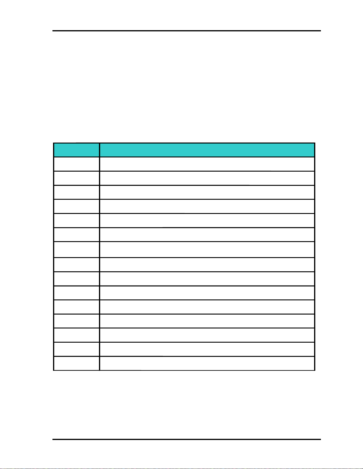
2.5 2.5-inch HDD 2 Troubleshooting
r
r
Procedure 4 Test Program Check
Run the HDD test program stored on the maintenance test program disk for all test items.
See Chapter 3 for details on how to use the test program.
If an error is detected during the HDD test, an error code and status will be displayed. The
error codes and their status names are listed in Table 2-1. If an error code is not generated
and the problem still exists, go to Procedure 5.
Table 2- 1 HDD error code and status
Code Status
1 Get Parameter Fail !
2
Read Old Data Error
3 Write Pattern Error
4 Read Back Data Error
5 Data Compare Error
6 Restore Data Error
7 Read Verify Error
9
Seek Error
10 Disk Controller Self Test Failed
11 Disk Controller Test unexpected interrupt Failed
12 Disk Controller action Test Failed
13 Disk dos not support SMART
14
Disk read attribute threshold erro
15 Disk read attribute value error
16 Disk SMART attribute value erro
Satellite A100/A105 / TECRA A7 Maintenance Manual 2-15
Page 58

2 Troubleshooting 2.5 2.5-inch HDD
Procedure 5 Connector Check and Replacement Check
The HDD or system board may be faulty. Disassemble the computer following the steps
described in Chapter 4 and perform the following checks:
Check 1 Make sure the following connectors have been firmly connected to the HDD,
system board and CPU.
HDD
System board
CPU
If any connector is loose or off, reconnect it firmly and return to Procedure 1.
If there is still an error, perform Check 2.
Check 2 The HDD may be damaged. Replace it with a new one following the
disassembling instructions in Chapter 4. If the problem persists, perform
Check 3.
Check 3 The System board may be damaged. Replace it with a new one following the
disassembling instructions in Chapter 4. If the problem persists, perform
Check 4.
Check 4 The CPU may be damaged. Replace it with a new one following the
disassembling instructions in Chapter 4.
2-16 Satellite A100/A105 / TECRA A7 Maintenance Manual
Page 59
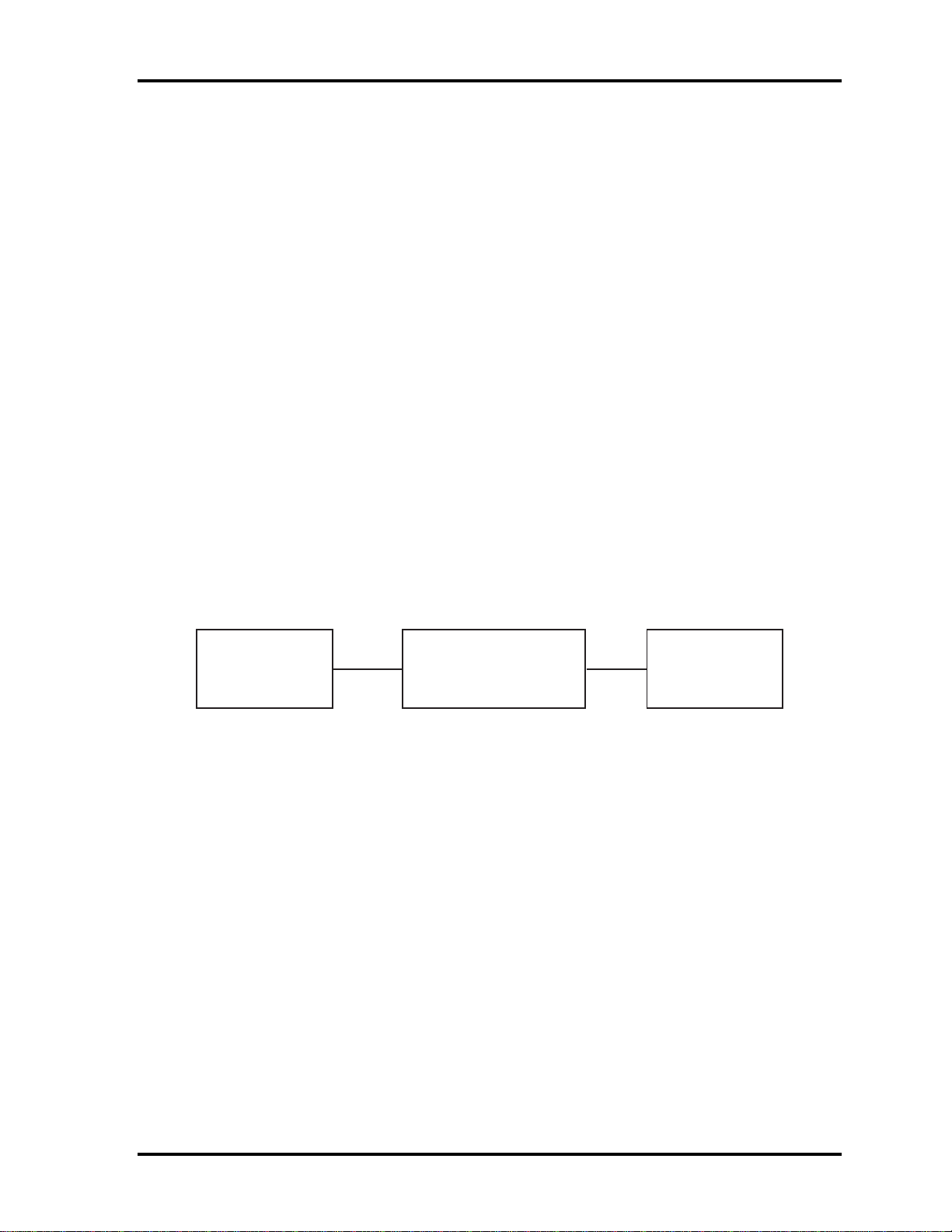
2.6 Keyboard 2 Troubleshooting
2.6 Keyboard
To check if the computer’s keyboard is defective or malfunctioning, follow the
troubleshooting procedures below as instructed.
Procedure 1 Test Program Check
Procedure 2 Connector Check and Replacement Check
Procedure 1 Test Program Check
Execute the Keyboard test available as part of the maintenance test program. See Chapter 3
for information on how to perform the test.
If an error is detected in the test, go to Procedure 2. If no error is detected, the keyboard
itself is normal.
Procedure 2 Connector Check and Replacement Check
The keyboard or system board may be disconnected or faulty. Disassemble the computer
following the steps described in Chapter 4 and perform the following checks:
Check 1 Make sure the keyboard cable has been firmly connected to the system board.
Keyboard
If the cable is loose or off, reconnect it firmly and return to Procedure 1. If
there is still an error, perform Check 2.
Check 2 The keyboard may be faulty. Replace it with a new one following the
instructions in Chapter 4. If the problem persists, perform Check 3.
Check 3 The System board may be faulty. Replace it with a new one following the
instructions in Chapter 4. If the keyboard is still not functioning properly,
perform Check 4.
Check 4 The memory may be defective. Replace the memory module with a new one
following the steps described in Chapter 4. If the problem persist, perform
Check 5.
Check 5 The CPU may be faulty. Disassemble the computer following the steps
described in Chapter 4 and replace the CPU with a new one.
System board
CPU
Satellite A100/A105 / TECRA A7 Maintenance Manual 2-17
Page 60

2 Troubleshooting 2.7 Display
2.7 Display
To check if the computer’s display is defective or malfunctioning, follow the troubleshooting
procedures below as instructed.
Procedure 1 External Monitor Check
Procedure 2 Test Program Check
Procedure 3 Connector Check and Replacement Check
Procedure 1 External Monitor Check
Connect an external monitor to the computer's external monitor port, then boot the computer.
The computer automatically detects the external monitor even if resume mode is enabled.
If the external monitor works correctly, the internal LCD, LCD/FL cable, or FL may be
faulty. Go to Procedure 3.
If the external monitor appears to have the same problem as the internal monitor, the system
board may be faulty. Go to Procedure 2.
Procedure 2 Test Program Check
Insert the diagnostics bootable CD in the computer's CD ROM, turn on the computer and run
the test. See Chapter 3 for information on how to perform the test.
If an error is detected in the test, go to Procedure 3. If no error is detected, the display itself
is normal.
Procedure 3 Connector Check and Replacement Check
The display unit has an LCD module, Fluorescent lamp (FL), panel close switch and FL
inverter board. Any of the components or their connections may be defective. Disassemble
the computer following the steps described in Chapter 4, then perform the following checks:
(1) If the FL does not light, perform Check 1.
(2) If characters or graphics are not displayed normally, perform Check 5.
(3) If the FL remains lit when the display is closed, the panel close switch may be
defective. Perform Check 8.
Check 1 Make sure the following cables have been firmly connected to the system
board and FL inverter board.
FL
FL inverter board
System board
CPU
HV cable LCD/FL cable
If any of the cables is loose or off, reconnect it firmly and return to Procedure
3. If there is still an error, perform Check 2.
Check 2 The LCD/FL cable may be faulty. Replace it with a new one and return to
Procedure 3. If there is still an error, perform Check 3.
2-18 Satellite A100/A105 / TECRA A7 Maintenance Manual
Page 61

2.7 Display 2 Troubleshooting
Check 3 The FL may be faulty. Replace it with a new one and return to Procedure 3. If
there is still an error, perform Check 4.
Check 4 The FL inverter board may be faulty. Replace it with a new one and return to
Procedure 3. If there is still an error, perform Check 5.
Check 5 Make sure the LCD/FL cable has been firmly connected to the system board
and LCD module.
FL inverter board
System board
LCD/FL cable
CPU
If the cable is loose or off, reconnect it firmly and return to Procedure 3. If
there is still an error, perform Check 6.
Check 6 The LCD/FL inverter cable may be faulty. Replace it with a new one and
return to Procedure 3. If there is still an error, perform Check 7.
Check 7 The LCD module may be faulty. Replace it with a new one and return to
Procedure 3. If there is still an error, perform Check 8.
Check 8 The System board may be faulty. Replace it with a new one. If there is still an
error, perform Check 9.
Check 9 The CPU may be faulty. Replace it with a new one following the instructions
in Chapter 4.
Check 10 The memory may be defective. Replace the memory module with a new one
following the steps described in Chapter 4. If the problem persist, perform
Check 10.
Satellite A100/A105 / TECRA A7 Maintenance Manual 2-19
Page 62
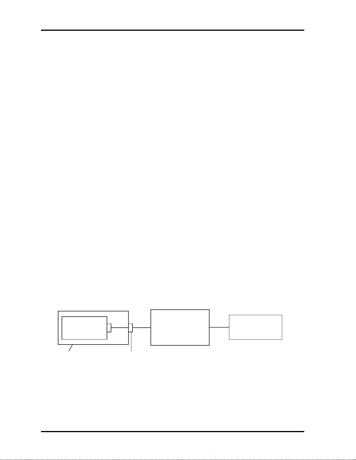
2 Troubleshooting 2.8 ODD Drive
2.8 ODD (Optical Disk Drive)
To check if the internal ODD drive is defective or malfunctioning, follow the troubleshooting
procedures below as instructed.
Procedure 1 ODD Cleaning Check
Procedure 2 Test Program Check
Procedure 3 Connector Check and Replacement Check
Procedure 1 ODD Cleaning Check
1. Turn off the power to the computer.
2. Open the ODD tray by inserting a slender object such as a straightened paper clip into
the eject hole. The object must be long enough to activate the eject mechanism.
3. Clean the laser pickup lens with a lens cleaner. Apply the cleaner to a cloth and wipe
the lens.
4. If the ODD drive still does not function properly after cleaning, go to Procedure 2.
Procedure 2 Test Program Check
Execute the ODD drive test program available as part of the maintenance test program. Insert
the diagnostics CD in the computer's CD, turn on the computer and run the test. Then insert a
test ODD (Toshiba-EMI DVD-ROM TEST DISK TSD-1) into the ODD drive. See Chapter 3
for information on how to perform the test.
If any error is detected by the test, go to Procedure 3.
Procedure 3 Connector Check and Replacement Check
The ODD drive is connected to the system board by the connector. The connector may be
disconnected from the system board or faulty. Disassemble the computer following the steps
described in Chapter 4 and perform the following checks:
Check 1 Make sure the following connector has been firmly connected to the ODD
drive and the system board.
ODD
drive
Attachment case
If the connector is loose or off, reconnect it firmly and return to Procedure 2.
If there is still an error, perform Check 2.
Check 2 The connector may be faulty. Replace the connector with a new one following
the steps in Chapter 4. If the ODD drive is still not functioning properly,
perform Check 3.
Connector
System board
CPU
2-20 Satellite A100/A105 / TECRA A7 Maintenance Manual
Page 63

2.8 ODD Drive 2 Troubleshooting
Check 3 The ODD drive may be faulty. Replace the ODD drive with a new one
following the steps in Chapter 4. If the ODD drive is still not functioning
properly, perform Check 4.
Check 4 The system board may be faulty. Replace it with new one following the
instructions in Chapter 4. If the ODD drive is still not functioning properly,
perform Check 5.
Check 5 The memory may be defective. Replace the memory module with a new one
following the steps described in Chapter 4. If the problem persist, perform
Check 6.
Check 6 The memory may be defective. Replace the memory module with a new one
following the steps described in Chapter 4. If the problem persist, perform
Check 3.
Satellite A100/A105 / TECRA A7 Maintenance Manual 2-21
Page 64

2 Troubleshooting 2.9 LAN
2.9 LAN
To check if the computer’s LAN is defective or malfunctioning, follow the troubleshooting
procedures below as instructed.
Procedure 1 Test Program Check
Procedure 2 Connector Check and Replacement Check
Procedure 1 Test Program Check
Execute the LAN check program available as part of the maintenance test program. This
program will check the LAN. Insert the Bootable CD into the CD. Turn on the computer
and run the check program. See Chapter 3 for information on how to perform the check.
If any abnormal is detected by the check, go to Procedure 2
Procedure 2 Connector Check and Replacement Check
The LAN connector (RJ45) is mounted on the system board. If the LAN malfunctions, the
system board or CPU might be faulty.
Disassemble the computer following the steps described in Chapter 4 and perform the
following checks:
Check 1 The system board may be faulty. Replace it with a new one following the
instructions in Chapter 4. If the LAN is still not functioning properly, perform
Check 2.
Check 2 The memory may be defective. Replace the memory module with a new one
following the steps described in Chapter 4. If the problem persist, perform
Check 3.
Check 3 The CPU may be faulty. Disassemble the computer following the steps
described in Chapter 4 and replace the CPU with a new one.
2-22 Satellite A100/A105 / TECRA A7 Maintenance Manual
Page 65

2.10 SD Card/Memory Stick 2 Troubleshooting
2.10 SD/MS/MS pro/MMC/XD Card(Optional)
To check if the computer’s SD/MS/MS Pro/MMC/XD Card is defective or malfunctioning,
follow the troubleshooting procedures below as instructed.
Procedure 1 Test Program Check
Procedure 2 Connector Check
Procedure 1 Test Program Check
Execute the SD/MS/MS Pro/MMC/XD Card test program available as part of the
maintenance test program. This program checks the SD/MS/MS Pro/MMC/XD card. Insert
the Bootable CD into the CD. Turn on the computer and run the test. See Chapter 3 for
information on how to perform the test.
If any error is detected by the test, go to Procedure 2
Procedure 2 Connector Check
The Memory Card connector is mounted on the system board. If the Memory Card
malfunctions, the system board or CPU might be faulty.
Disassemble the computer following the steps described in Chapter 4 and perform the
following checks:
Check 1 The system board may be faulty. Replace it with a new one following the
instructions in Chapter 4. If the Memory Card is still not functioning properly,
perform Check 2.
Check 2 The memory may be defective. Replace the memory module with a new one
following the steps described in Chapter 4. If the problem persist, perform
Check 3.
Check 3 The CPU may be faulty. Disassemble the computer following the steps
described in Chapter 4 and replace the CPU with a new one.
Satellite A100/A105 / TECRA A7 Maintenance Manual 2-23
Page 66

2 Troubleshooting 2.11 Finger Print(Optional)
2.11 Finger Print(Optional)
To check if the computer’s Finger Print is defective or malfunctioning, follow the
troubleshooting procedures below as instructed.
Procedure 1 Test Program Check
Procedure 2 Connector Check
Procedure 1 Test Program Check
Execute the Finger Print test program available as part of the maintenance test program. This
program checks the Finger Print. Insert the Bootable CD into the CD. Turn on the computer
and run the test. See Chapter 3 for information on how to perform the test.
If any error is detected by the test, go to Procedure 2
Procedure 2 Connector Check
The Finger Print connector is mounted on the system board. If the Finger Print
malfunctions, the system board or Finger Print Board might be faulty.
Disassemble the computer following the steps described in Chapter 4 and perform the
following checks:
Check 1 The Finger Print board may be faulty. Replace it with a new one following the
instructions in Chapter 4. Then go through procedure 1 again.If the Finger
Print is still not functioning properly, perform Check 2.
Check 2 The system board may be defective. Replace the system board with a new one
following the steps described in Chapter 4. Then go through procedure 1 again
.
2-24 Satellite A100/A105 / TECRA A7 Maintenance Manual
Page 67

2.12 2 Troubleshooting 3D Sensor
2.12 3D Sensor
To check if the computer’s 3D sensor is defective or malfunctioning, follow the
troubleshooting procedures below as instructed.
Procedure 1 Test Program Check
Procedure 2 Replacement Check
Procedure 1 Test Program Check
Execute the 3D sensor test program available as part of the maintenance test program. This
program checks the3D sensor. Insert the Bootable CD into the CD. Turn on the computer
and run the test. See Chapter 3 for information on how to perform the test.
If any error is detected by the test, go to Procedure 2
Procedure 2 Replacement Check
The 3D sensor chipset is mounted on the system board. If the 3D sensor malfunctions, the
system board might be faulty.
Disassemble the computer following the steps described in Chapter 4 and perform the
following checks:
Check 1 The system board may be faulty. Replace it with a new one following the
instructions in Chapter 4. Then go through procedure 1 again .
Satellite A100/A105 / TECRA A7 Maintenance Manual 2-25
Page 68

2 Troubleshooting 2.13 Parallel Port(Optional)
2.13 Parallel Port(Optional)
To check if the computer’s Parallel Port is defective or malfunctioning, follow the
troubleshooting procedures below as instructed.
Procedure 1 Test Program Check
Procedure 2 Connector Check
Procedure 1 Test Program Check
Execute the Parallel Port test program available as part of the maintenance test program.
This program checks the Parallel Port. Insert the Bootable CD into the CD. Turn on the
computer and run the test. See Chapter 3 for information on how to perform the test.
If any error is detected by the test, go to Procedure 2
Procedure 2 Connector Check
The Parallel Port connector is mounted on the parallel board. If the Parallel Port
malfunctions, the parallel board or or cable or system board or CPU might be faulty.
Disassemble the computer following the steps described in Chapter 4 and perform the
following checks:
Check 1 The parallel board may be faulty. Replace it with a new one following the
instructions in Chapter 4. If the Parallel Port is still not functioning properly,
perform Check 2.
Check 2 The parallel board cable may be faulty. Replace it with a new one following
the instructions in Chapter 4. If the Parallel Port is still not functioning
properly, perform Check 3.
Check 3 The system board may be faulty. Replace it with a new one following the
instructions in Chapter 4. If the Parallel Port is still not functioning properly,
perform Check 4.
Check 4 The memory may be defective. Replace the memory module with a new one
following the steps described in Chapter 4. If the problem persist, perform
Check 5.
Check 5 The CPU may be faulty. Disassemble the computer following the steps
described in Chapter 4 and replace the CPU with a new one.
2-26 Satellite A100/A105 / TECRA A7 Maintenance Manual
Page 69
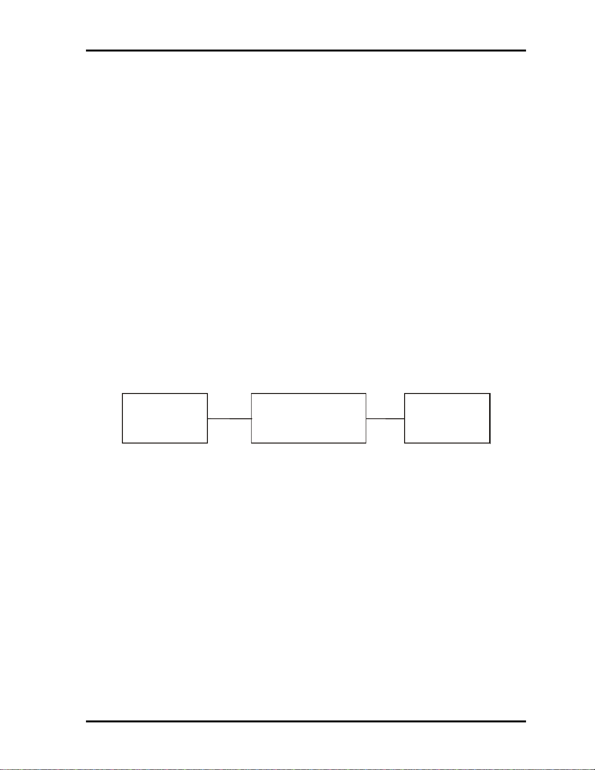
2.13 2 Troubleshooting Audio Test
r
2.14 Audio Test
To check if the computer’s Speaker is defective or malfunctioning, follow the
troubleshooting procedures below as instructed.
Procedure 1 Test Program Check
Procedure 2 Connector Check and Replacement Check
Procedure 1 Test Program Check
Execute the Audio test available as part of the maintenance test program. See Chapter 3 for
information on how to perform the test.
If an error is detected in the test, go to Procedure 2. If no error is detected, the Audio itself is
normal.
Procedure 2 Connector Check and Replacement Check
The Audio or system board may be disconnected or faulty. Disassemble the computer
following the steps described in Chapter 4 and perform the following checks:
Check 1 Make sure the Speaker cable has been firmly connected to the system board.
Speake
If the cable is loose or off, reconnect it firmly and return to Procedure 1. If
there is still an error, perform Check 2.
Check 2 The Speaker may be faulty. Replace it with a new one following the
instructions in Chapter 4. If the problem persists, perform Check 3.
Check 3 The System board may be faulty. Replace it with a new one following the
instructions in Chapter 4. If the Audio is still not functioning properly,
perform Check 4.
Check 4 The memory may be defective. Replace the memory module with a new one
following the steps described in Chapter 4. If the problem persist, perform
Check 5.
Check 5 The CPU may be faulty. Disassemble the computer following the steps
described in Chapter 4 and replace the CPU with a new one.
System board
CPU
Satellite A100/A105 / TECRA A7 Maintenance Manual 2-27
Page 70

2 Troubleshooting 2.15 IEEE 1394 Test
2.15 IEEE 1394 Test
To check if the computer’s IEEE 1394 is defective or malfunctioning, follow the
troubleshooting procedures below as instructed.
Procedure 1 Test Program Check
Procedure 2 Connector Check
Procedure 1 Test Program Check
Execute the IEEE 1394 test program available as part of the maintenance test program. This
program checks the IEEE 1394. Insert the Bootable CD into the CD. Turn on the computer
and run the test. See Chapter 3 for information on how to perform the test.
If any error is detected by the test, go to Procedure 2
Procedure 2 Connector Check
The IEEE 1394 connector is mounted on the system board. If the IEEE 1394 malfunctions,
the system board or CPU might be faulty.
Disassemble the computer following the steps described in Chapter 4 and perform the
following checks:
Check 1 The system board may be faulty. Replace it with a new one following the
instructions in Chapter 4. If the IEEE 1394 is still not functioning properly,
perform Check 2.
Check 2 The memory may be defective. Replace the memory module with a new one
following the steps described in Chapter 4. If the problem persist, perform
Check 3.
Check 3 The CPU may be faulty. Disassemble the computer following the steps
described in Chapter 4 and replace the CPU with a new one.
2-28 Satellite A100/A105 / TECRA A7 Maintenance Manual
Page 71

2.16 2 Troubleshooting Cooling Module
2.16 Cooling Module
To check if the computer’s cooling module is defective or malfunctioning, follow the
troubleshooting procedures below as instructed.
Procedure 1 Test Program Check
Procedure 2 Connector Check and Replacement Check
Procedure 1 Test Program Check
Execute the Fan On/Off test program available as part of the maintenance test program. This
test program checks the cooling module. Insert the diagnostics bootable CD in the
computer's CD, turn on the computer and run the test. See Chapter 3 for information on how
to perform the test.
If any error is detected by the test, go to Procedure 2.
Procedure 2 Connector Check and Replacement Check
The cooling module is connected to the system board. If the cooling module malfunctions,
there may be a bad connection between the cooling module and the system board or either
might be faulty.
Disassemble the computer following the steps described in Chapter 4 and perform the
following checks:
Check 1 Make sure the cooling module has been firmly connected to the connector on
the system board. Also make sure that the tape is not stuck to any part of the
fan and that the fan is free of foreign matter.
Cooling module
If the connector is disconnected, connect it firmly to the system board and
return to Procedure 1. If the tape is stuck to any part of the fan, stick it back to
the specified point. If a foreign matter is found in the fan, remove it and then
return to Procedure 1. If there is still an error, perform Check 2.
Check 2 The cooling module may be faulty. Replace it with a new one following the
steps in Chapter 4. If the cooling module is still not functioning properly,
perform Check 3.
Check 3 The memory may be defective. Replace the memory module with a new one
following the steps described in Chapter 4. If the problem persist, perform
Check 4.
Check 4 The CPU may be faulty. Disassemble the computer following the steps
described in Chapter 4 and replace the CPU with a new one.
Satellite A100/A105 / TECRA A7 Maintenance Manual 2-29
System board
CPU
Page 72

2 Troubleshooting 2.16 Cooling Module
2-30 Satellite A100/A105 / TECRA A7 Maintenance Manual
Page 73

Chapter 3 Diagnostic Programs
Page 74

3 Diagnostic Programs
Chapter 3 Contents
3.1 General.......................................................................................................................... 1
3.2 Quick Start.................................................................................................................... 3
3.2.1 Quick Test ............................................................................................... 3
3.2.2 Customization Test.................................................................................. 3
3.2.3 Keyboard Layout test .............................................................................. 7
3.2.4 Hotkey Test ............................................................................................. 8
3.2.5 Audio Play Test....................................................................................... 8
3.2.6 Audio Record Test................................................................................... 8
3.2.7 DMI Read................................................................................................ 8
3.2.8 DMI Write............................................................................................... 9
3.2.9 3D Sensor Test ...................................................................................... 10
3.2.10 FPRD Test............................................................................................ 16
3.2.11 FENR Test............................................................................................ 16
3.2.12 IrDA ManMaster Test........................................................................... 16
3.2.13 IrDA ManSlave Test ............................................................................. 17
3.2.14 System Information............................................................................... 17
3.2.15 View Logs ............................................................................................. 19
3.2.16 Exit to MS DOS .................................................................................... 19
3.2.17 The Diagnostics Screen Explanation..................................................... 19
3.3 Options........................................................................................................................ 23
3.3.1 Overview ............................................................................................... 23
3.3.2 Batch Parameters Configuration ........................................................... 24
3.3.3 Item’s Parameters Configuration........................................................... 26
3.3.4 Load Batch Parameters.......................................................................... 27
3.3.5 Save Batch Parameters.......................................................................... 28
3.3.6 LOG Parameters Setting........................................................................ 28
3.3.7 Specify LOG Viewer............................................................................. 29
3.3.8 Display LOG File.................................................................................. 30
3.3.9 LOG Viewer.......................................................................................... 30
3.3.10 LOG File Sample................................................................................... 32
ii Satellite A100/A105 / TECRA A7 Maintenance Manual
Page 75

3 Diagnostic Programs
3.4 Subtests....................................................................................................................... 33
3.5 System Test................................................................................................................. 36
3.6 Memory Test............................................................................................................... 40
3.7 Storage........................................................................................................................ 46
3.8 Video........................................................................................................................... 50
3.9 Communication (COMM) .......................................................................................... 59
3.10 Peripheral.................................................................................................................... 61
3.11 Error Codes and description........................................................................................ 63
3.12 Quick Test Item List ...................................................................................................... i
Satellite A100/A105 / TECRA A7 Maintenance Manual iii
Page 76

Page 77

3.1 General 3 Diagnostic Programs
3.1 General
This chapter explains the diagnostic programs which tests and diagnoses the functions of the
hardware components of this computer. The diagnostic programs can be classified into two
types: OPTION and DIAGNOSTIC TEST.
NOTE 1: This Diagnostic supports Satellite A100/A105 / TECRA A7
NOTE 2: Before running a test, be sure to:
1. Check that all the cables are connected securely.
2. Exit the application that is currently running and close Windows.
The OPTION includes the following functions:
Select All Items
Test All Items
Edit Batch Parameters
Load Batch Parameters
Save Batch Parameters
Log Parameters
Specify Log Viewer
Display Error Log File
DOS Shell
Exit to DOS
The DIAGNOSTIC TEST Devices include the following tests:
System Test
Memory Test
Storage Test
Video Test
Communication Test
Peripheral Test
Audio Test
DMI Read/Write
System Information
Before running the diagnostic programs, get the following tools prepared:
A Service Diagnostic BOOT CD
A Formatted FLOPPY DISK
A Test Media CD (A-BEX TEST CD-ROM TCDR-702)(for CD-ROM test)
A Test Media DVD (Toshiba-EMI DVD-ROM TEST DISK TSD-1)
An External Monitor (for DISPLAY test)
A CD-ROM Driver (for CD-ROM test)
Satellite A100/A105 / TECRA A7 Maintenance Manual 1
Page 78

3 Diagnostic Programs 3.1 General
Audio Line for audio record test
Loop back connector of LPT
A Data CD (for CD-ROM test)
The following chapters describe all the test details. The test items could be selected from the
DIAGNOSTIC TEST menu.
Note:
When booting up the unit for the first time, the system will automatically select the location
of the result log file. If a USB floppy drive is connected, and there is an unprotected floppy
diskette with more then 50KB spare space in the drive, system will save all log files into the
root directory the diskette; otherwise, system will save all log files in the root directory of
RAM disk.
2 Satellite A100/A105 / TECRA A7 Maintenance Manual
Page 79

3.2 Quick Start 3 Diagnostic Programs
3.2 Quick Start
When the system is booting from Service Diagnostic CD, the following screen will be displayed:
Please select a test item or select 0 to exit to MS-DOS:
3.2.1 Quick Test
When this item is selected, the system will run the configured test items and generate a test
report automatically.
When the test is completed, a file named Quick.log would be saved in the defined location.
When Quick.log is being created, meanwhile, a file named quick.log has already existed, the
system will automatically rename Quick.log to Quick.old for the backup purpose of the log file.
For the detail of test item, please refer to Quick Test Item List.
3.2.2 Customization Test
When this item is selected, the system will run the diagnostic programs according to the
procedures you defined. When the test is completed, a file named Custom.log will be saved in
the defined location. Please see the following example-- Mouse test.
1. Use arrow key to select ‘TouchPad’ item on ‘Peripheral’ in the menu, then press Space
key to select it. (When it is being selected, there is a X marked in the [ ])
Satellite A100/A105 / TECRA A7 Maintenance Manual 3
Page 80

3 Diagnostic Programs 3.2 Quick Start
Select ‘Test Mouse’ or press F8 to run the test. The prompt information would be
displayed in the screen as below. This test item needs user to verify whether the mouse
works normally.
The test result will be displayed in the following screen:
4 Satellite A100/A105 / TECRA A7 Maintenance Manual
Page 81

3.2 Quick Start 3 Diagnostic Programs
Here is another method to run the test: Highlight a test item by using arrow keys, then,
press Enter to start. If there are parameters provided, user should set parameters in the
parameter dialog window.
CPU Speed Test (Step by Step):
1. Select test item:
Select System—CPU—CPU Speed, then, press the Enter key.
2. Parameters Setting
Choose the OK button after you set the proper parameters in the following window.
Satellite A100/A105 / TECRA A7 Maintenance Manual 5
Page 82

3 Diagnostic Programs 3.2 Quick Start
3. Test Result
System will automatically run and display the test result as follows:
Following is the comparison report of the two testing methods mentioned above:
1) Configuration and Running
As to the method used in Mouse test, the user is required to select test items by pressing
Space key and set the parameters artificially, (See
3.3.3 Item’s Parameters
Configuration) Then press F8 to start the test. User should configure each parameter in
advance; otherwise the default parameters would be used. Using this method, user is
allowed to select more than one test item at one time.
2) Running the current test item
As to the method adopted in CPU Speed test, user should highlight the test item and
press Enter to start testing. And the user has to setup the parameters every time before
running the test. Using this method, only one test item would be tested at one time.
6 Satellite A100/A105 / TECRA A7 Maintenance Manual
Page 83
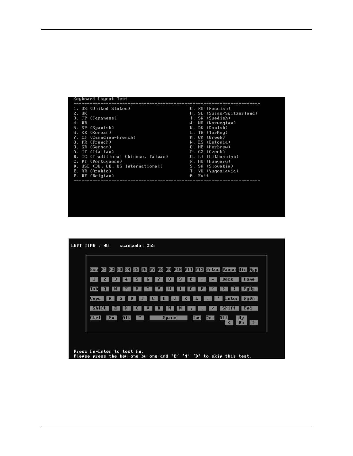
3.2 Quick Start 3 Diagnostic Programs
3.2.3 Keyboard Layout test
The test purpose is to check whether 18 kinds of European keyboards run well during the
test procedure. When users choose the item, the names of these countries will be
displayed on the screen for user choice. User press any index of token in ASCII, and the
program will test the kind of keymap of the country.
The test screen would be shown as below:
It requires user to press the key and check whether the key in the screen changes
color or not. User can terminate test by typing ‘END’. When testing the ‘Fn’ key, it
must press the ‘Enter’ key at the same time.
Satellite A100/A105 / TECRA A7 Maintenance Manual 7
Page 84

3 Diagnostic Programs 3.2 Quick Start
When the user has checked all the keys and all the keys in the screen have changed
color, the diagnostics program would automatically end the test and report the pass
information.
If keyboard test fails, program will terminate the test and report the fail information
when it is time to timeout.
The test will end when all keys are pressed or test time is out after 100 seconds.
3.2.4 Hotkey Test
Check whether Hotkey run well. Hotkey test mainly functional keys, for example: IE
Key Audio play etc. The methods of testing hotkey are different from keyboard tests
sometimes depending on the specific type of notebooks, and this explains why some
types of notebooks can be tested together with keyboard while others cannot. Press E+
+N+D to quit the test.
3.2.5 Audio Play Test
Check whether the system could playback audio normally. When the test is completed, a
file named Audio_P.log will be saved in the defined location.
3.2.6 Audio Record Test
Check whether the system could record the sound normally. If there is no error during
the whole test, Pass; otherwise Fail. The test will repeat for four times. When the test is
completed, a file named autest.log will be saved in the defined location.
3.2.7 DMI Read
Read the information from the system’s SMBIOS and display it in the screen as follows:
8 Satellite A100/A105 / TECRA A7 Maintenance Manual
Page 85
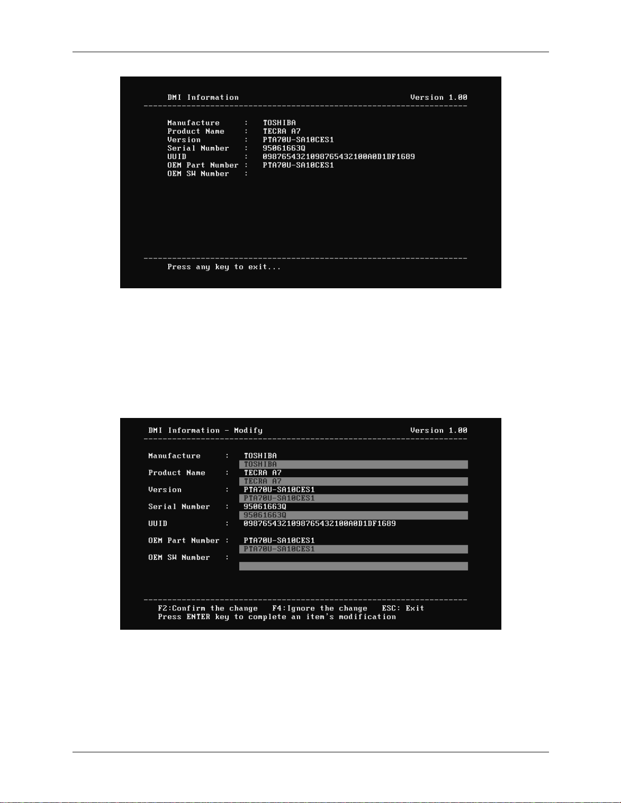
3.2 Quick Start 3 Diagnostic Programs
User can press any key to exit the program.
3.2.8 DMI Write
In addition to reading the DMI information, DMI Write also permits attributes editing
and updating: Manufacture, Product Name, Version, Serial Number, and OEM Part
Number, etc. The following screen will be displayed:
In this screen, there are two lines which attribute could be edited and updated. The 1
line (the font in yellow with blue background) shows the attribute’s value that is read
from the current system and the 2nd line (the font in red with turquoise background)
shows the same value as that in the 1st line before user’s editing. User can modify the
nd
attribute’s value in the 2
line and press Enter to confirm the current edition and
continue editing the next attribute.
Satellite A100/A105 / TECRA A7 Maintenance Manual 9
st
Page 86

3 Diagnostic Programs 3.2 Quick Start
During the editing, user could press F2 to confirm the DMI attribute update or press F4 to
ignore the modification. Press ESC to exit the program of DMI Write.
The confirmation screen is as below:
The attributes that have been modified would be marked in red; otherwise in yellow.
User could press F2 to save the changes, or press F4 to ignore and exit the current
program.
3.2.9 3D Sensor Test
In 3D Sensor test, the system checks whether the HDD protection is normal. This
program judges by sampling five kinds of data shown below.
No Item Contents
1 Access
An access platform is leveling.
platform.
The Fixture which fixes PC by 90 degree inclination is used. 2 Test
Fixture
Vibration/shock doesn't take a PCB at the time of T&D inspection.
10 Satellite A100/A105 / TECRA A7 Maintenance Manual
Page 87

3.2 Quick Start 3 Diagnostic Programs
3 Test1
The display of a test program and the set method of PC are shown below.
Display of a Test Program
The portion which PC and Test-Fixture contact is green.
Set method of PC
Z
Upper
X
Judgment
If all data is less than ranges, it will be OK.
Satellite A100/A105 / TECRA A7 Maintenance Manual 11
Page 88

3 Diagnostic Programs 3.2 Quick Start
4 Test2
The display of a test program and the set method of PC are shown below.
Display of a Test Program
Set method of PC
Rear
Upper
Judgment
If all data is less than ranges, it will be OK.
12 Satellite A100/A105 / TECRA A7 Maintenance Manual
Page 89

3.2 Quick Start 3 Diagnostic Programs
5 Test3
The display of a test program and the set method of PC are shown below.
Display of a Test Program
Set method of PC
Right
Upper
Judgment
If all data is less than ranges, it will be OK.
Satellite A100/A105 / TECRA A7 Maintenance Manual 13
Page 90

3 Diagnostic Programs 3.2 Quick Start
6 Test4
The display of a test program and the set method of PC are shown below.
Display of a Test Program
Set method of PC
Front
Upper
Judgment
If all data is less than ranges, it will be OK.
14 Satellite A100/A105 / TECRA A7 Maintenance Manual
Page 91

3.2 Quick Start 3 Diagnostic Programs
7 Test5
The display of a test program and the set method of PC are shown below.
Display of a Test Program
Set method of PC
Left
8 Inspection
9 Setting
Calibration
data
If it succeeded, the system will prompt a message of PASS, otherwise the message will
be FAIL.The test information will be written in log file.
Note:
Please do not use this program, when you test PC without 3D sensor.
Upper
Judgment
If all data is less than ranges, it will be OK.
Judgment
If all data is less than ranges, it will be OK.
When an inspection result is O.K., calibration at HPC.
Satellite A100/A105 / TECRA A7 Maintenance Manual 15
Page 92

3 Diagnostic Programs 3.2 Quick Start
3.2.10 FPRD Test
Both FPRD and FENR refer to finger print test, which means finger print identification
system. FPRD, a self test of finger print test, detects the existence of the device. If it
exists, the system will prompt a message of PASS, otherwise the message will be FAIL.
3.2.11 FENR Test
In FENR test, the system scans a finger print for three times and displays Succeeded if
successfully collected finger print information. Then it will scan the finger print one
more time for comparison and display PASS if succeeded. If the comparison is not
successful, the system will request another scan for totally five times and display FAIL if
it always fails.
Note:
Because, execution of this test vanishes all fingerprint data. When you perform this test,
please make it only failure of a fingerprint sensor.
3.2.12 IrDA ManMaster Test
This test item supports the transfer rates of 2.4Kbps, 9.6Kbps, 19.2Kbps, 38.4Kbps,
57.6Kbps, 115.2Kbps , 0.576Mbps,1.152Mbps and 4.00Mbps. The unit under testing
(UUT) is called Slave, that requires a unit whose IrDA works normally(that is called
Master) for transferring data between Slave and Master.
Below are the operation steps:
Prepare a Master whose IrDA works normally, then run the test item from
Main Menu, The master stays here to wait for slave requesting.
Prepare a slave. User should choose the test item from Main Menu and set
parameters.
Below is the Master Testing window:
16 Satellite A100/A105 / TECRA A7 Maintenance Manual
Page 93

3.2 Quick Start 3 Diagnostic Programs
Press any key to quit when you want to stop
3.2.13 IrDA ManSlave Test
Below is the Slave Testing window.
3.2.14 System Information
This function is used to read the system information. When the test is completed, a file
named System.log will be saved in the defined location. During the reading process, the
following screen will be displayed to indicate that the progress is in detection:
Satellite A100/A105 / TECRA A7 Maintenance Manual 17
Page 94

3 Diagnostic Programs 3.2 Quick Start
On the left column of the above screen, the detected hardware components are listed. The
corresponding information of the detected hardware components is displayed on the right
of the screen. It displays the current running status information of the check program.
The name of the program is marked on the top of the screen. At the bottom, the function
keys are listed for user operation. During the detection, keyboard operation is invalid.
When the detection is finished, the hardware components information will be displayed
as follows:
User can use function keys listed on the bottom of the screen to display the configuration
of the component or exit the current program. On the left column, the components
information is listed and user can use arrow keys or PgUp/PgDn to view the list and
highlight the chosen component. On the right column, the configuration information of
the highlighted component is listed. Press ESC to exit this program.
18 Satellite A100/A105 / TECRA A7 Maintenance Manual
Page 95

3.2 Quick Start 3 Diagnostic Programs
3.2.15 View Logs
User can enter one choice to view a log file in the screen as follows.
3.2.16 Exit to MS DOS
Select this item to exit to MS DOS.
3.2.17 The Diagnostics Screen Explanation
Below is an example of running a test item. It includes the following parts: Diagnostics
Windows, Test Status Area, Progress Bar, Error List, Test Item’s Title, Status Bar and
Message Box.
Satellite A100/A105 / TECRA A7 Maintenance Manual 19
Page 96
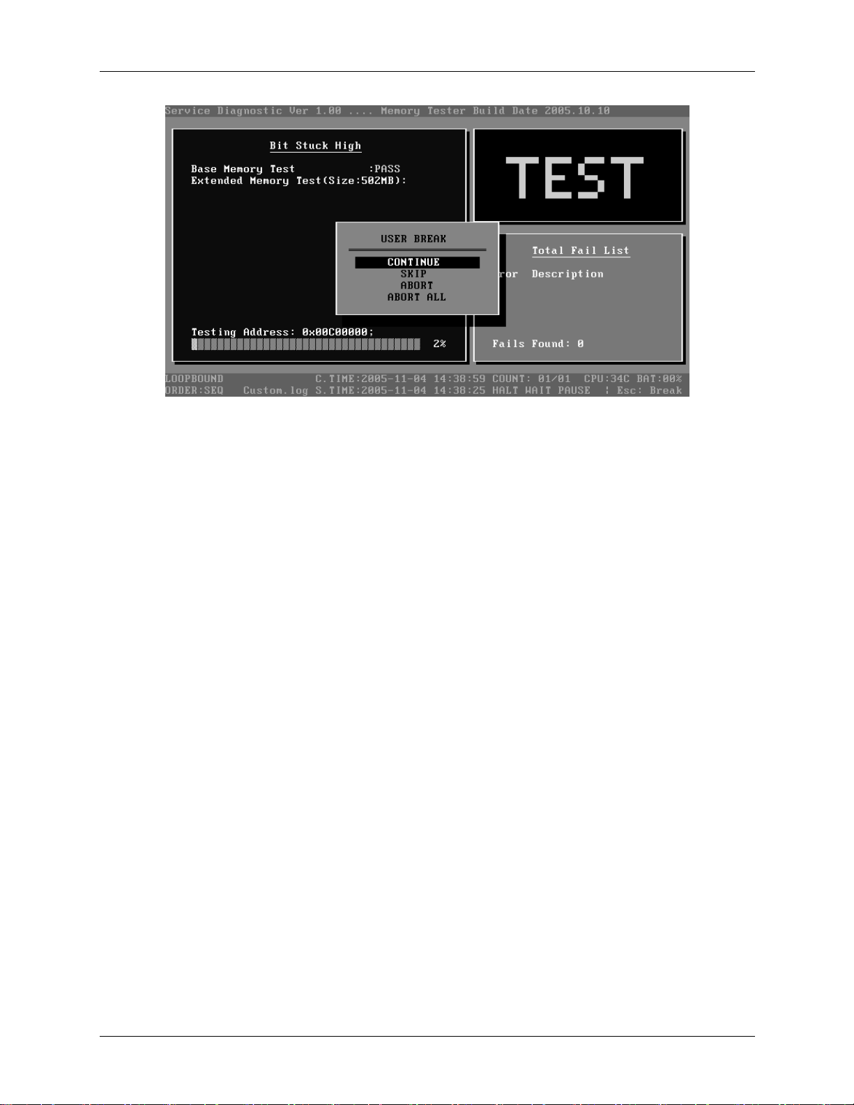
3 Diagnostic Programs 3.2 Quick Start
1. Diagnostics Windows
When a test item is running, a Diagnostics Windows is displayed in full screen. It consists of
the following parts: Title Bar, Test Running Status and Report Panel, Status Bar. There
would prompt a message box called USER BREAK in the central of the window whether
user press ESC to interrupt the test.
2. Test Running Status and Report Panel
Test Running Status and Report Panel are located on the middle of Diagnostics Windows.
Test item name, test process and test result are displayed in the left;
Test status and result are displayed in the upper right corner of the screen. It displays the
test status of the current test item – TEST (in testing), PASS (test finished and its result
is passed), FAIL (test finished and its result is failed) and SKIP (test skipped).
The error list of each test module is displayed at the lower right corner of the screen. It
would display the total error quantity found in the test, the most recent five error codes
and description would be shown here. Detailed error report could be viewed with
Logview.exe.
When pressing ESC key during the test process, a User Break Windows will be popped
up for the user to select.
3. USER BREAK
20 Satellite A100/A105 / TECRA A7 Maintenance Manual
Page 97

3.2 Quick Start 3 Diagnostic Programs
Pressing ESC key to interrupt the test, USER BREAK message box would be prompted out
in the central of Diagnostics Window for the user to select the following actions:
CONTINUE---- Continue the test;
SKIP---- Stop the sub-item of current test item to go to the next item’s test;
ABORT----Stop the current test item to test the next module.
ABORT ALL---- Stop all the selected test items. User could use the hot key Ctrl+D to
achieve the same operation. When the user calls ABORT ALL, the following message
box will prompt for his selecting.
4. Title Bar:
Title Bar located at the top of the window, it includes information as follows:
Program Name and Its Version: Service Diagnostic Ver1.10;
Test Module Name: Label the name and version of the test module. For example, in the
above screen, the name of the test module is ‘Memory Tester Build Date 2002.12.31’.
Status Bar: Located at the bottom of the screen as follows:
The status bar is used to indicate the current script setting and test status. It consists of two
lines that includes the information as follows:
Test Mode: TIMEBOUND or LOOPBOUND, e.g. LOOPBOUND in the above screen;
Script File Name: Script file name, e.g. ‘Quick.INI’ in the above screen;
Current Time(C. TIME): Current system time, e.g. ‘C.TIME:2004-01-04 19:21:27’ in the
above screen;
Test Time Remaining (LEFT): In TIMEBOUND mode, it would display the remaining
test time at the same location as Current TIME (C. TIME) in the above screen;
Current Loop Count: In LOOPBOUND mode, it will display the total LOOP number
planning to execute and the current LOOP number have been finished, e.g. ‘COUNT:
01/01’ in the above screen;
Satellite A100/A105 / TECRA A7 Maintenance Manual 21
Page 98

3 Diagnostic Programs 3.2 Quick Start
CPU Temperature: Detect the temperature in the current CPU, e.g. ‘CPU: 49C’ in the
above screen;
Remaining Battery Capacity: Remaining Battery Capacity detected in the current
Battery, e.g. ‘BAT: 97%’;
Test Order: Define the test sequence. There is two sequence modes: Sequential Test
Mode and Random Test Mode. The default mode is Sequential Test Mode, it would
displays ‘ORDER: SEQ’ as in the above screen;
LOG File Name: Display the file name of the test log, e.g. Quick.Log in the above
screen;
Start Test Time (S.TIME): Display the test start time for the current test item or the test
script, e.g. ‘S.TIME: 2004-01-04 19:21:16’ in the above screen;
Break On Error: Display ‘HALT’ as shown in the above screen when ‘Break On Error’ is
enabled;
Wait On Error: Display ‘WAIT’ as shown in the above screen when ‘Wait On Error’ is
enabled;
Pause Enable: Display ‘PAUSE’ when “Pause Enable” is enabled;
Manual Interrupt Method: Display ‘Esc: Break’ to tell the user how to manually interrupt
the test process.
22 Satellite A100/A105 / TECRA A7 Maintenance Manual
Page 99

3.3 Option 3 Diagnostic Programs
3.3 Options
3.3.1 Overview
In Service Diagnostics, with the Options menu user can configure the batch
parameters, test item’s parameters and those parameters created by the LOG file.
Options Menu Notes:
• Select All/None Items
Switch between selecting all test items and selecting none. The hot key is F6.
• Test Selected Items
Execute all selected test items in this editor. The hot key is F8.
If “Interactive” option in batch parameters has not been selected, a warning
message would be shown as below:
• Edit Batch Parameters
Satellite A100/A105 / TECRA A7 Maintenance Manual 23
Page 100

3 Diagnostic Programs 3.3 Option
Configure batch parameters and all the test item’s parameters.
• Load Batch Parameters
Upload all the test items and the parameters to the *.ini file.
• Save Batch Parameters
Save all the parameters and the test items that are configured in the editor to a
specified file.
• Log Parameters
Configure LOG parameters.
• Specify LOG Viewer
Specify the viewer for the LOG file.
• Display Error Log File
Load the LOG file viewer specified in the Specify Log Viewer to view the LOG
file.
• DOS Shell
Enter the DOS Shell and execute the DOS programs. You can also exit to the
Service Diagnostics Editor by the command of EXIT.
• Exit to DOS
Exit the Service Diagnostics Editor and back to DOS.
3.3.2 Batch Parameters Configuration
The batch parameters configuration screen can be accessed through Service
Diagnostics/OPTIONS -> EDIT BATCH PARAMETERS -> BATCH
PARAMETERS:
24 Satellite A100/A105 / TECRA A7 Maintenance Manual
 Loading...