

Toshiba Satellite L730, Satellite 735, Satellite Pro 730 Maintenance Manual

Chapter 1
Hardware Overview
Satellite L730/Satellite 735/Satellite Pro 730 Maintenance Manual (960-Q08)

Chapter1 Hardware Overview
1 Hardware Overview
Chapter 1 Contents
1.1 Features ......................................................................................................................... 1
1.2 System Block Diagram ................................................................................................. 5
1.3 2.5-inch Hard Disk Drive .............................................................................................. 8
1.4 Optical Drive ............................................................................................................... 11
1.4.1 DVD Super Multi Drive ........................................................................ 11
1.4.2 Bule Ray ODD ...................................................................................... 11
1.5 Keyboard ..................................................................................................................... 13
1.6 Color Display .............................................................................................................. 14
1.7 Power Rails ................................................................................................................. 15
1.8 Batteries ...................................................................................................................... 16
1.8.1 Main Battery .......................................................................................... 16
1.8.2 Battery Charging Control ...................................................................... 17
1.8.3 RTC battery ........................................................................................... 18
1.9 AC Adapter ................................................................................................................. 19
Satellite L730/Satellite 735/Satellite Pro 730 Maintenance Manual (960-Q08)

Chapter1 Hardware Overview
Figures
Figure 1-1-1 Left of the computer .......................................................................................... 3
Figure 1-1-2 Right of the computer ....................................................................................... 4
Figure 1-2-1 System Block Diagram for Intel Platform ........................................................ 5
Figure 1-3-1 2.5-inch HDD ................................................................................................... 8
Figure 1-5-1 Keyboard for US Style .................................................................................... 13
Figure 1-6-1 LCD Module………… ......................... ……………………………………..14
Tables
Table 1-3-1 2.5-inch HDD dimensions ................................................................................ 9
Table 1-3-2 2.5-inch HDD Specification ............................................................................ 10
Table 1-4-1 DVD Super Multi drive outline dimensions ................................................... 11
Table 1-4-2 DVD Super Multi drive specifications ........................................................... 11
Table 1-4-3 Blue Ray ODD outline dimensions ................................................................. 12
Table 1-4-4 Blue Ray ODD outline specifications ............................................................. 12
Table 1-6-1 LCD module specifications ............................................................................. 14
Table 1-7-1 Power supply output rating ............................................................................. 15
Table 1-8-1 Battery specifications ...................................................................................... 16
Table 1-8-2 Time required for charges of main battery ..................................................... 17
Table 1-8-3 Data preservation time .................................................................................... 17
Table 1-8-4 Time required for charges of RTC battery ...................................................... 18
Table 1-9-1 AC adapter specifications ............................................................................... 19
Satellite L730/Satellite 735/Satellite Pro 730 Maintenance Manual (960-Q08)

Chapter 1 Hardware Overview
1.1 Features
The Satellite L730/Satellite 735/Satellite Pro 730 (Intel Platform) features are listed below.
Microprocessor
Microprocessor that is used will be different by the model.
It supports processors as follows
Intel® Huron River-Sandy Bridge Dual Core
Memory
Two DDRIII SO-DIMM (1333MHz specification compliant) used and be up to 8GB
which can be upgraded through Memory Module Slot. Maximum upgradeable system
memory may depend on the model
VRAM
Shared with System RAM for Intel UMA
HDD
5400RPM: 2.5 inch x 9.5mm height.
ODD
12.7mm DVD SMD (Tray) / BD-ROM (Tray) / BD-RE (Tray)
Display
LCD
13-inch, Aspect ratio 16:9, HD, 1366x768, LED type
Dimension 308 x 183 x 5.05 mm
CRT
Supported via a RGB connector.
Keyboard
TOSHIBA 2010 new A4, 300 x 110.85 x 4.75 mm
Satellite L730/Satellite 735/Satellite Pro 730 Maintenance Manual (960-Q08)
1

Chapter 1 Hardware Overview
Battery
The RTC battery is equipped inside the computer.
The main battery is a detachable lithium ion battery.
5600mAh, 4400mAh
USB (Universal Serial Bus)
3 USB ports are provided. The ports comply with the USB2.0 standard. One port
comply with USB3.0.(On the right).USB Sleep and Charge function can be supported
by only the USB3.0 port (.If USB Sleep and Charge function is enabled, the
computer’s battery will discharge during hibernation or when the computer is turned
off. It is recommended that user connect the AC adaptor to the computer when
enabling the USB Sleep and Charge function.
Sound system
Internal stereo speaker, Internal MIC (Option) external monaural microphone
connector, stereo headphone connector.
Wireless LAN
Half x 1 WiFi/WiMAX/BT (BT combo module with WLAN)
LAN
The computer has built-in support for Ethernet LAN (10 megabits per second,
10BASE-T) and Fast Ethernet LAN (100 megabits per second, 100 BASE-TX)
SD/SDHC/MS/MS pro/MMC are supported.
Bluetooth Combo with WLAN
Bluetooth V3.0 + HS support ready (BT combo module with WLAN) (BTO)
Security
Kensington Lock,
Hard Disk Drive Password
3D Accelerometer for Hard Disk Drive
Satellite L730/Satellite 735/Satellite Pro 730 Maintenance Manual (960-Q08)
2

Chapter 1 Hardware Overview
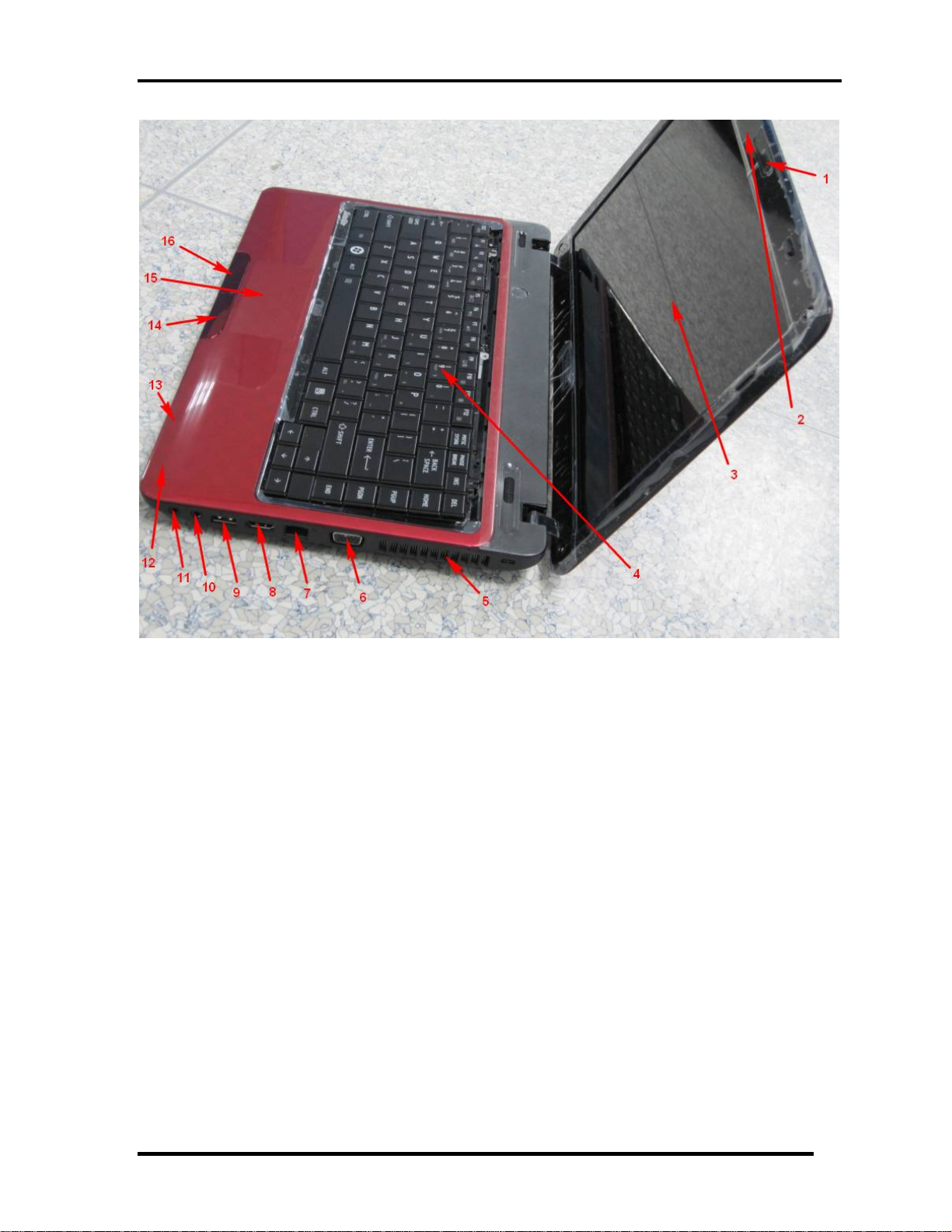
1. Power Button
2. DC-IN jack
3. USB2.0 port
4. USB2.0 port
5. ODD
Figure 1-1-1 Left of the computer
Satellite L730/Satellite 735/Satellite Pro 730 Maintenance Manual (960-Q08)
3
Chapter 1 Hardware Overview
1. Web Camera 2. Microphone
3. Display Screen 4. Keyboard
5. FAN HOLE 6. Extend Monitor connector
7. LAN Jack 8. HDMI out port
9. USB3.0 port 10. Microphone jack
11. Headphone Jack 12.
13. LED light indicator
14. Touch Pad Control Right Button
15. Touch Pad
16. Touch Pad Control Left Button
Top Cover censer
Figure 1-1-2 Right of the computer
Satellite L730/Satellite 735/Satellite Pro 730 Maintenance Manual (960-Q08)
4
Chapter 1 Hardware Overview
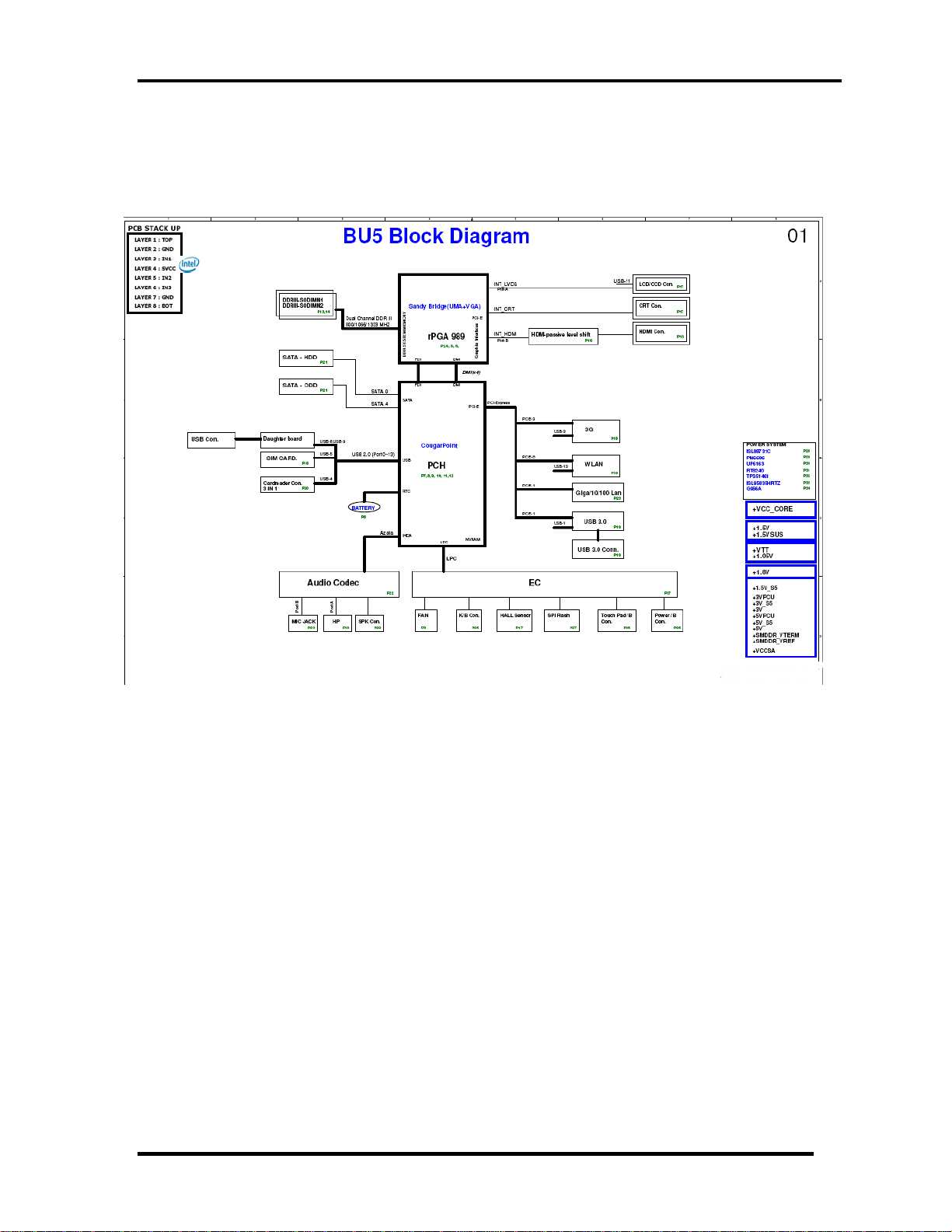
1.2 System Block Diagram
Figure 1-2-1 shows the system block diagram.
Figure 1-2-1 System block diagram for Intel Platform
Satellite L730/Satellite 735/Satellite Pro 730 Maintenance Manual (960-Q08)
5

Chapter 1 Hardware Overview
6
The PC contains the following components.
CPU
Intel® Huron River-Sandy Bridge Dual Core
Memory
Two memory slots capable of accepting DDRIII-SDRAM 1GB, 2GB 4GB, or 8GB
memory modules for a maximum of 16GB.(TBD)
204-pin SO-DIMM
1.5V operation
BIOS ROM (Flash memory)
4MB
Chipset
This gate array has the following elements and functions.
PCH (Cougar Point HM65)
Direct Media Interface (DMI)
Flexible Display Interface(FDI)
PCI Express
Serial ATA (SATA) Controller
Low Pin count (LPC) interface
Serial Peripheral Interface (SPI)
Advanced Programmable Interrupt Controller (APIC)
USB Controllers
RTC
GPIO
Enhanced Power Management
SMBus 2.0
High Definition Audio Controller
Other main system chips
• EC/KBC –[W/CIR(Winbond WPCE791CA0DG)]
• HD Audio (CONEXANT CX20582-21Z)
Satellite L730/Satellite 735/Satellite Pro 730 Maintenance Manual (960-Q08)

Chapter 1 Hardware Overview
7
• Card Reader controller (REALTEAK RTS5209)
• 10/100 LAN controller (Atheros AR8152)
Mini Card
Wireless LAN (BTO)
IEEE802.11a/g/n
Wireless WAN (BTO)
HSPA
Blue tooth
Bluetooth V3.0 + HS support ready (BTO)
Satellite L730/Satellite 735/Satellite Pro 730 Maintenance Manual (960-Q08)
Chapter 1 Hardware Overview
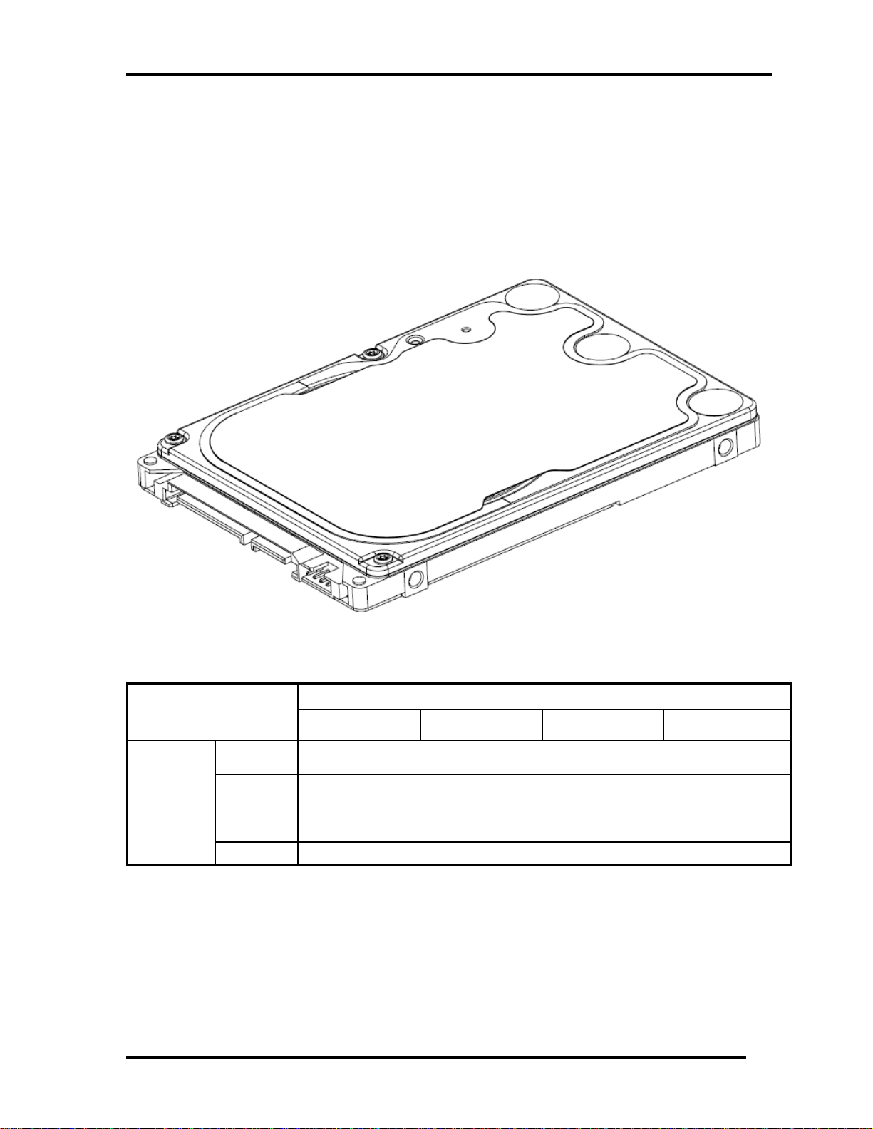
1.3 2.5-inch Hard Disk Drive
A compact, high-capacity HDD with a height of 9.5mm contains 2.5-inch magnetic disks and
magnetic heads.
Figure 1-3-1 shows a view of the 2.5-inch HDD and Tables 1-3-1 and 1-3-2 list the
specifications.
Parameter
Outline
dimensions
Figure 1-3-1 2.5-inch HDD
Standard value
TOS
MK3276GSXN
Width
(mm)
Height
(mm)
Depth
(mm)
Weight (g) 101(typ.)/102(max.)
TOS
MK5065GSXN
TOS
MK6465GSXN
69.85
9.5
100
TOS
MK7559GSXP
Satellite L730/Satellite 735/Satellite Pro 730 Maintenance Manual (960-Q08)
8
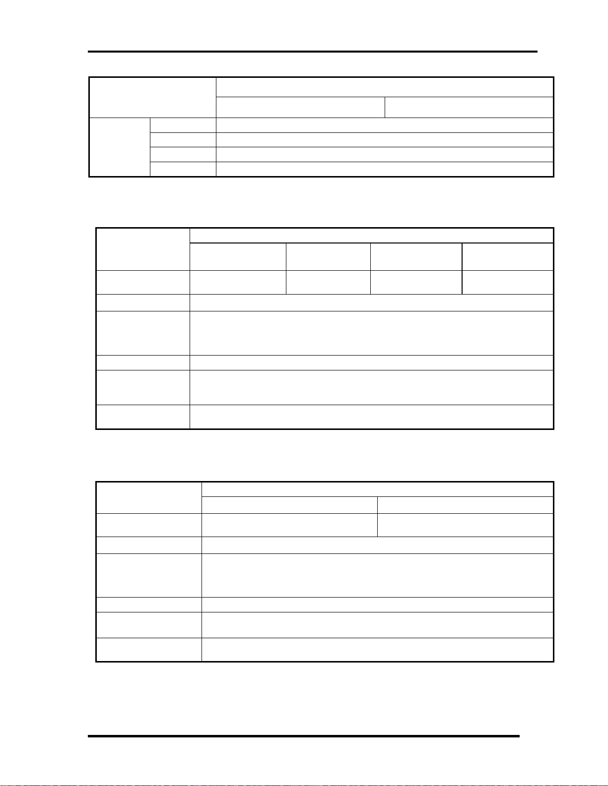
Chapter 1 Hardware Overview
Standard value
Parameter
Outline
dimensions
Width (mm) 69.85
Height(mm) 9.5
Depth (mm) 100
Weight (g) 101(Max)
HTS547550A9E384 HTS547564A9E384
Table 1-3-1 2.5-inch HDD dimensions
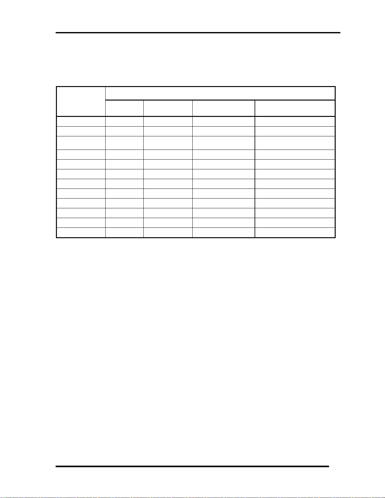
Specification
Parameter
Storagesize
(formatted)
Speed (RPM) 5400
Data transfer Rate
- To/From Media 464~1148MB/S
- To/From Host 3GB/S
Bus Transfer Rate 3GB/S
Average random
seek time (read)
(ms)
Power-on-to-ready
(sec)
TOS
MK3276GSXN
320G 500GB 640GB 750GB
TOS
MK5065GSXN
TOS
MK6465GSXN
TOS
MK7559GSXP
12
3.5
Parameter
Storage size
(formatted)
Speed (RPM)
Data transfer Rate
- To/From Media
- T0/From Host
Bus Transfer Rate 3GB/S
Average random
seek time (read) (ms)
Power-on-to-ready
(sec)
HTS547550A9E384 HTS547564A9E384
500G 640G
Specification
5400
363~952MB/S
3GB/S
12
3.5
Table 1-3-2 2.5-inch HDD Specification
Satellite L730/Satellite 735/Satellite Pro 730 Maintenance Manual (960-Q08)
9
Chapter 1 Hardware Overview
1.4 Optical Drive
1.4.1 DVD Super Multi Drive
The DVD Super Multi drive accommodates either 12 cm (4.72-inch) or 8 cm (3.15-inch)
CD/DVD-ROM, CD-R/RW, DVD±R/±RW and DVD-RAM. It is a high-performance drive
that reads DVD-ROM at maximum 8-speed and CD at maximum 24-speed. Write speed of
DVD±R/±RW and DVD-RAM is different depending on the drive.
Parameter Standard value
Maker
Outline
dimensions
Data transfer speed
Width (mm) 128
Height (mm) 12.7
Depth (mm) 129
Mass (g)
Parameter
Panasonic
(UJ8A0EDTJL-B)
165 +/- 10
Table 1-4-1 DVD Super Multi drive outline dimensions
Drive Specification
Panasonic (UJ8A0EDTJL-B / UJ8A0ADTJL-B)
DVD-ROM MAX 8X CAV (MAX 10800 KB/s)
Read (KB/s)
Write
CD-ROM
CD-R :Max24X CAV
CD-RW :4X CLV
High Speed CD-RW :10XCLV
Ultra Speed CD-RW :Max 24X Zone CLV
DVD-R :Max.8X CAV
DVD-R DL :Max.3.3x-6X PCAV
DVD-RW :Max.6X Zone CLV
DVD+R :Max.8X CAV
DVD+R DL :Max.3.3x-6X PCAV
DVD+RW :Max.8X Zone CLV
DVD-RAM :Max.3-5X PCAV (4.7GB)
MAX 24X CAV (MAX 3600 KB/s)
Panasonic
(UJ8A0ADTJL-B)
Access time (ms)
(Random)
Buffer memory
SATA interface
(MB/s)
CD-ROM 150ms (Typ.)
DVD-ROM 180ms (Typ.)
150
1MB
Table 1-4-2 DVD Super Multi drive specifications
Satellite L730/Satellite 735/Satellite Pro 730 Maintenance Manual (960-Q08)
10
Chapter 1 Hardware Overview
1.4.2 Blue Ray ODD
The Blue Ray ODD accommodates either 12 cm (4.72-inch) or 8 cm (3.15-inch) CD/DVDROM, CD-R/RW, DVD±R/±RW and DVD-RAM. It is a high-performance drive that reads
DVD-ROM at maximum 8-speed, CD at maximum 24-speed and BD at maximum 6-speed.
Write speed of DVD±R/±RW and DVD-RAM is different depending on the drive.
Parameter Standard value
Maker
Panasonic
(UJ240EJTJL-B)
HLDS
(CT31F-ATAK7B0)
Outline
dimensions
Data transfer speed
Width (mm) 128
Height (mm) 12.7
Depth (mm) 129
Mass (g)
Parameter
185 +/- 10
Table 1-4-3 Blue Ray ODD outline dimensions
Drive Specification
MAT (UJ8A0EDTJL/UJ8A0ADTJL) HLDS(CT30F-ATAK7N2)
DVD-ROM MAX 8X CAV (MAX 10800 KB/s)
Read (KB/s)
Write
SATA interface
(MB/s)
CD-ROM
BD-ROM 1.6x CLV(for Video)/Max 6X CAV(for Data)
CD-R Max.24X Zone CLV
CD-RW 4X (CLV)
High Speed CD-RW 10X (CLV)
Ultra Speed CD-RW Max 16X Zone CLV
DVD-R :Max.8X CAV
DVD-R DL :Max.4X Zone CLV
DVD-RW :Max.6X Zone CLV
DVD+R :Max.8X CAV
DVD+R DL :Max.4X Zone CLV
DVD+RW :Max.8X Zone CLV
DVD-RAM :3X-5X PCAV ( 4.7GB)
BD-R :6X CAV ( SL), 4XPCAV (DL)
BD-RE :2X CLV ( SL), 2XCLV (DL)
MAX 24X CAV (MAX 3600 KB/s)
150
CD-ROM 180ms (Typ.)
Access time (ms)
(Random)
Buffer memory
DVD-ROM 190ms (Typ.)
BD-ROM
300ms(Typ.)
2MB
Table 1-4-4 Blue Ray ODD outline specifications
Satellite L730/Satellite 735/Satellite Pro 730 Maintenance Manual (960-Q08)
11
Chapter 1 Hardware Overview
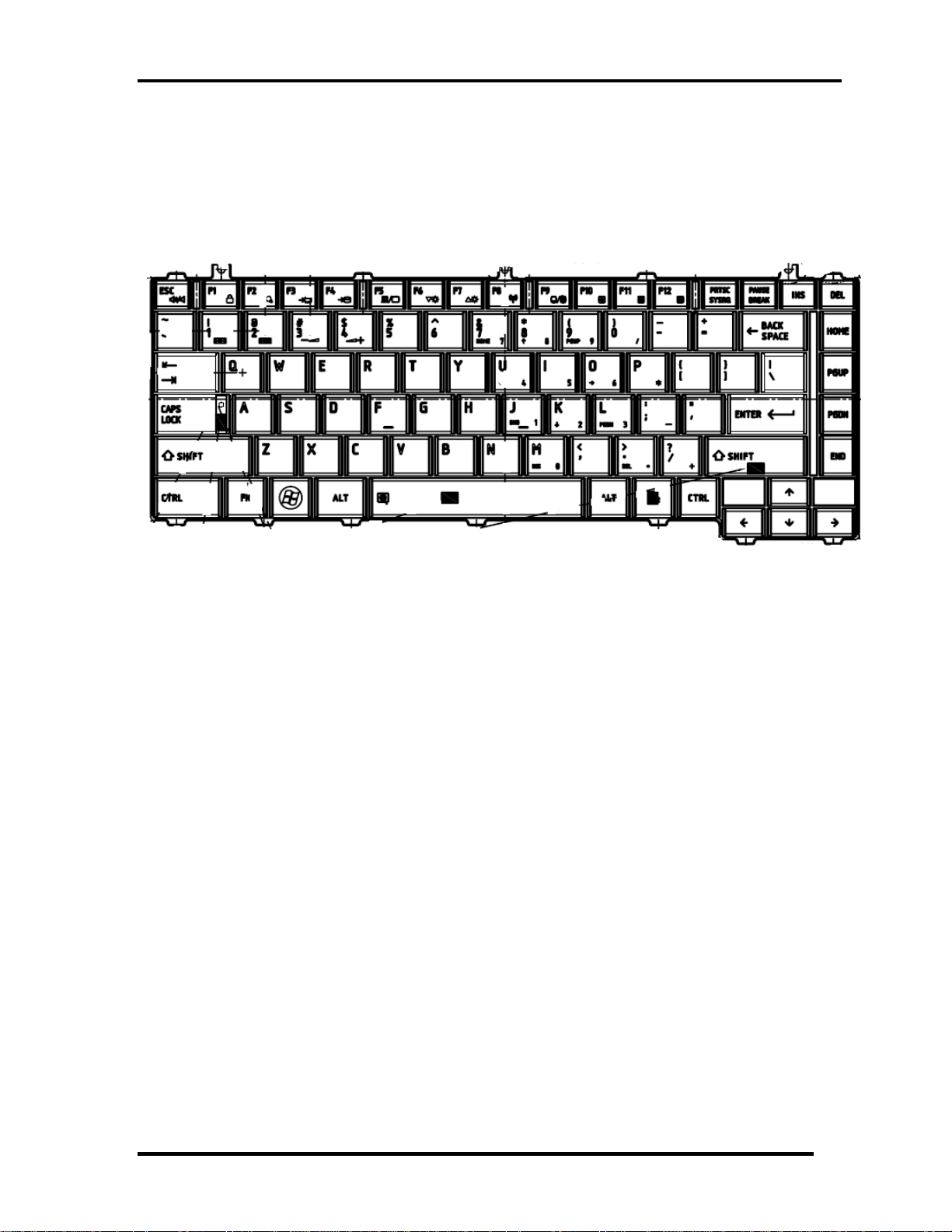
1.5 Keyboard
The Satellite E300/E305 keyboard is for US style
Figure 1-5-1 is a view of the keyboard for US style
Figure 1-5-1 Keyboard for US style
See Appendix E for details of the keyboard layout
Satellite L730/Satellite 735/Satellite Pro 730 Maintenance Manual (960-Q08)
12
Chapter 1 Hardware Overview
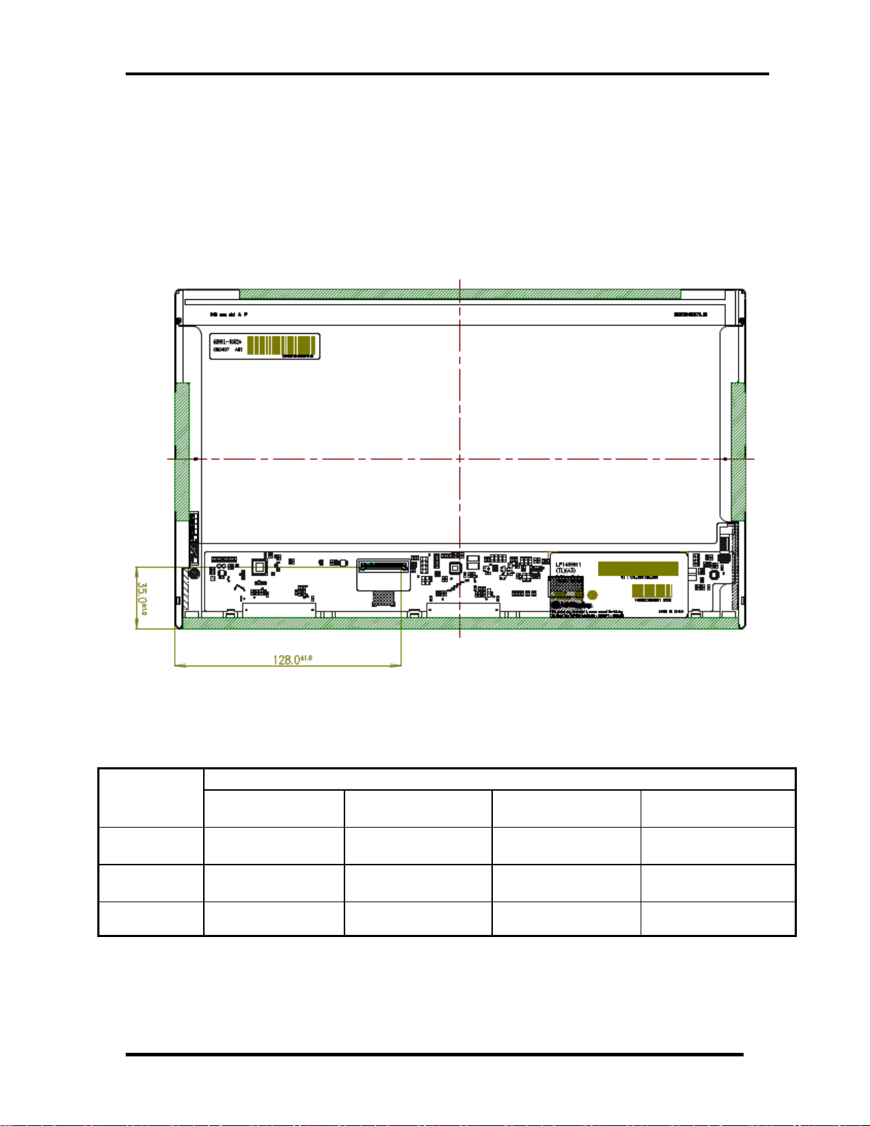
1.6 Color Display
The Satellite L730/Satellite 735/Satellite Pro 730use LED to control backlight.
LCD Module
Figure 1-5-1 shows a view of the LCD module and Table 1-6-1 lists the specifications.
Figure 1-6-1 LCD Module
Specifications(WXGA+)
Item
Number of
Dots
Dot spacing
(mm)
Display
Colors
SAMSUNGA
LTN133AT17-T05
1,366 x 3(R,G,B) x
768
0.2148(H)×
0.2148(V)
262,144 colors 262,144 colors 262,144 colors 262,144 colors
LP133WH1-TLA1
1,366 x 3(R,G,B) x
LG
768
0.2148(H)×
0.2148(V)
CMO
N133BGE-L21
1,366 x 3(R,G,B) x
768
0.2148(H)×
0.2148(V)
AUO
B133XW04
1,366 x 3(R,G,B) x
768
0.2148(H)×
0.2148(V)
Table 1-6-1 LCD module specifications
Satellite L730/Satellite 735/Satellite Pro 730 Maintenance Manual (960-Q08)
13
Chapter 1 Hardware Overview
1.7 Power Rails
Table 1-7-1 lists the power rail output specifications of Huron River platform.
Power supply (Yes/No)
Name
VA1
VIN
+5VPCU
Voltage [V]
19.37 2.123 19.40 1.733
19.19 12.45 19.22 12.31
5.150
Power OFF
Suspend mode
5.148
Power OFF
Boot mode
5.157
No Battery
5.152
+3VPCU
+3V_S5
+3V
+5V_S5
+5V
+VCC_CORE
+VTT
+VAXG
+1.5VSUS
3.389 3.387 3.389 3.386
3.387 3.385 3.386 3.385
0 0 0 0
5.148 5.146 5.155 0
0 0 0 0
0 0 0 0
0 0 0 0
0 0 0 0
1.507 1.507 0 0
Table 1-7-1 Power supply output rating
Satellite L730/Satellite 735/Satellite Pro 730 Maintenance Manual (960-Q08)
14

Chapter 1 Hardware Overview
1.8 Batteries
The PC has the following two batteries.
Main battery
Real time clock (RTC) battery
Table 1-8-1 lists the specifications for these two batteries.
Battery Name Battery Element Output Voltage
Main battery
6 Cells Lithium ion 10.8 V
Real time clock
(RTC) battery
COIN Type Lithium ion 3V
Table 1-8-1 Battery specifications
1.8.1 Main Battery
The main battery is the primary power supply for the computer when the AC adapter is not
connected. In Standby, the main battery maintains the current status of the computer.
Satellite L730/Satellite 735/Satellite Pro 730 Maintenance Manual (960-Q08)
15

Chapter 1 Hardware Overview
6
1.8.2 Battery Charging Control
Battery charging is controlled by a power supply microprocessor. The power supply
microprocessor controls power supply and detects a full charge when the AC adaptor and
battery are connected to the computer.
Battery Charge
When the AC adapter is connected, normal charging is used while the system is
turned on and quick charge is used while the system is turned off. Refer to the
following Table 1-8-2.
Power ON Power OFF
6 cell 5 ~ 10 hours about 5 hours
Table 1-8-2 Time required for charges of main battery
Charge is stopped in the following cases.
1. The main battery is fully charged
2. The main battery is removed
3. Main battery or AC adapter voltage is abnormal
4. Charging current is abnormal
Data preservation time
When turning off the power in being charged fully, the preservation time is as
following Table 1-8-3.
Sleep Shut down
6 cell About 3 days About 30 days
Table 1-8-3 Data preservation time
Satellite L730/Satellite 735/Satellite Pro 730 Maintenance Manual (960-Q08)
1
Chapter 1 Hardware Overview
7
1.8.3 RTC Battery
The RTC battery provides the power supply to maintain the date, time, and other system
information in memory.
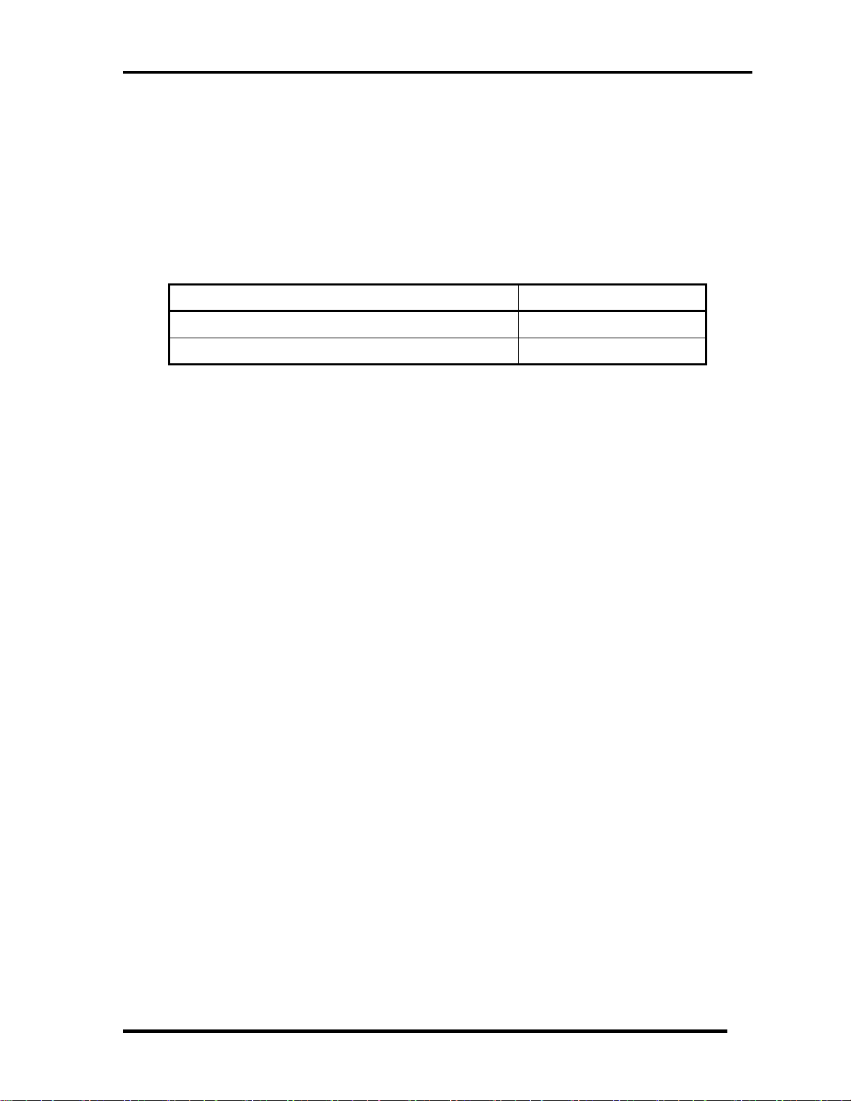
Table 1-8-4 lists the Time required for charges of RTC battery and data preservation time.
Condition Time
Charging time About 24 hours
Data retaining time About 30 days
Table 1-8-4 Time required for charges of RTC battery
Satellite L730/Satellite 735/Satellite Pro 730 Maintenance Manual (960-Q08)
1
Chapter 1 Hardware Overview
1.9 AC Adapter
The AC adapter is used to charge the battery.
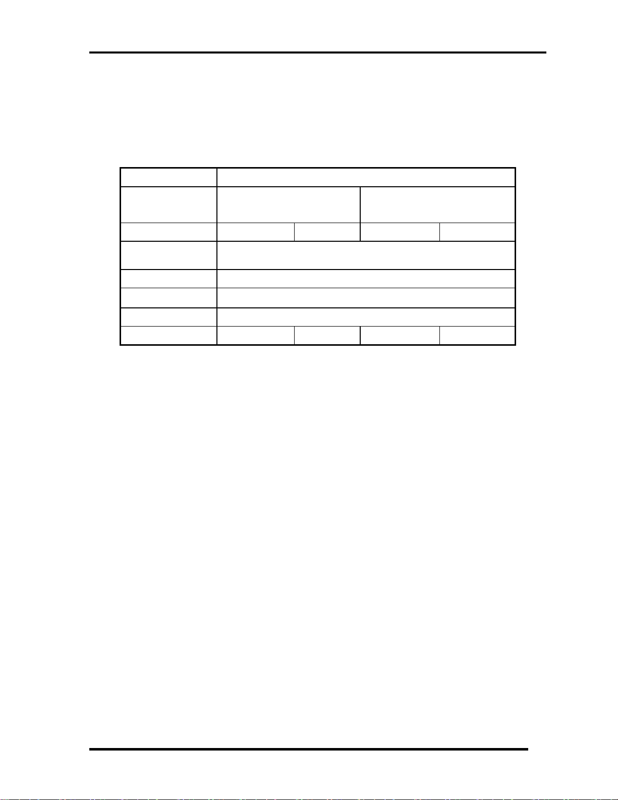
Table 1-9-1 lists the AC adapter specifications.
Parameter
With Led
Power 65W 75W 65W 75W
Input voltage AC 90V/264V
Input frequency 50Hz/60Hz
Input current
Output voltage DC 19V
Output current 3.42A 3.95A 3.42A 3.95A
DELTA/ LITE-ON/Chiony
3pin
Specification
DELTA/ LITE-ON/Chiony
2pin
≦1.5A
Table 1-9-1 AC adapter specifications
Satellite L730/Satellite 735/Satellite Pro 730 Maintenance Manual (960-Q08)
18

Chapter 2
Troubleshooting Procedures
Satellite E300/E305 Maintenance Manual (960-Q08)

Chapter 2 Troubleshooting Procedures
Chapter 2 Contents
Chapter 2 Contents
2.1 Troubleshooting ............................................................................................................ 1
2.2 Troubleshooting Flowchart ........................................................................................... 2
2.3 Power Supply Troubleshooting ..................................................................................... 6
Procedure 1 Power Status Check .................................................................. 6
Procedure 2 Connection Check ..................................................................... 8
Procedure 3 Charging Check ........................................................................ 8
Procedure 4 Replacement Check .................................................................. 9
2.4 System Board Troubleshooting ................................................................................... 10
Procedure 1 Message Check ....................................................................... 11
Procedure 2 Diagnostic Test Program Execution Check ............................ 12
Procedure 3 Replacement Check ................................................................ 12
2.5 SATA Hard Disk Drive Troubleshooting ................................................................... 13
Procedure 1 Partition Check ........................................................................ 13
Procedure 2 Message Check ....................................................................... 14
Procedure 3 Diagnostic Test Program Execution Check ............................ 15
Procedure 4 Connector Check and Replacement Check ............................. 16
2.6 Keyboard Troubleshooting ......................................................................................... 17
Procedure 1 Diagnostic Test Program Execution Check ............................ 17
Procedure 2 Connector Check and Replacement Check ............................. 18
2.7 Touch pad Troubleshooting ........................................................................................ 19
Procedure 1 Diagnostic Test Program Execution Check ............................ 19
Procedure 2 Connector Check and Replacement Check ............................. 20
2.8 Display Troubleshooting ............................................................................................. 21
Procedure 1 External Monitor Check .......................................................... 21
Procedure 2 Diagnostic Test Program Execution Check ............................ 21
Procedure 3 Connector and Cable Check .................................................... 22
Procedure 4 Replacement Check ................................................................ 23
2.9 LAN Troubleshooting ................................................................................................. 24
Procedure 1 Diagnostic Test Program Execution Check ............................ 24
Satellite E300/E305 Maintenance Manual (960-Q08)

Chapter 2 Troubleshooting Procedures
Procedure 2 Connector Check and Replacement Check ............................. 24
2.10 Wireless LAN and Bluetooth Troubleshooting .......................................................... 25
Procedure 1 Transmitting-Receiving Check ............................................... 25
Procedure 2 Antennas' Connection Check .................................................. 26
Procedure 3 Replacement Check ................................................................ 27
2.11 Sound Troubleshooting ............................................................................................... 28
Procedure 1 Connector Check ..................................................................... 28
Procedure 2 Replacement Check ................................................................ 29
2.12 ODD Troubleshooting ................................................................................................ 30
Procedure 1 Connector Check and Replacement Check ............................ 30
2.13 HDMI Troubleshooting .............................................................................................. 31
Procedure 1 Connector Check and Replacement Check ............................. 31
Procedure 2 External Monitor Check .......................................................... 31
Procedure 3 Replacement Check ................................................................ 32
2.14 Memory Troubleshooting ........................................................................................... 33
Procedure 1 Diagnostic Test Program Execution Check ............................ 33
Procedure 2 Connect Check and Replacement Check ................................ 33
2.15 3G Troubleshooting .................................................................................................... 34
Procedure 1 Connect Check and Replacement Check ................................ 34
2.16 Camera Troubleshooting ............................................................................................. 35
Procedure 1 Camera Execution Check ........................................................ 35
Procedure 2 Connect Check and Replacement Check ................................ 35
2.17 Microphone Troubleshooting ...................................................................................... 36
Procedure 1 Sound Recorder Execution Check .......................................... 36
Procedure 2 Connect Check and Replacement Check ................................ 36
2.18 CRT Troubleshooting ................................................................................................. 37
Procedure 1 External Monitor Check .......................................................... 37
Procedure 2 Connector and Cable Check .................................................... 37
Procedure 3 Replacement Check ................................................................ 37
2.19 USB Troubleshooting ................................................................................................. 38
Procedure 1 Diagnostic Test Program Execution Check ............................ 38
Procedure 2 Connect Check and Replacement Check ................................ 38
Satellite E300/E305 Maintenance Manual (960-Q08)

Chapter 2 Troubleshooting Procedures
d
y
2
2.1 Trouble shooting
Chapter 2 describes how to determine which Field Replaceable Unit (FRU) in the computer
is causing the computer to malfunction.
The FRUs covered are:
1. Power supply 7. LAN 13. 3G
2. System Board 8.WLAN+BT 14. Camera
3. SATA HDD 9. Soun
4. Keyboard 10. ODD 16. Ext CRT
5. Touch pad 11. HDMI 17. USB
6. Display 12. Memor
The Test Program operations are described in Chapter 3. Detailed replacement procedures are
described in Chapter 4.
NOTE: After replacing the system board, it is necessary to execute the subtest 01 initial
configuration of the 3.3 Setting of the hardware configuration in Chapter 3.
15. Microphone
The implement for the Diagnostics procedures is referred to Chapter 3. Also, following
implements are necessary:
1. Phillips screwdrivers (For replacement procedures)
2. Implements for debugging port check
Toshiba Free-DOS system
Satellite L730/Satellite 735/Satellite Pro 730 Maintenance Manual (960-Q08)
1

Chapter 2 Troubleshooting Procedures
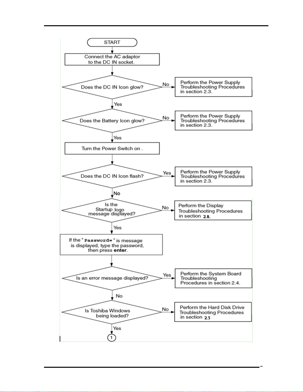
2.2 Troubleshooting Flowchart
Use the flowchart in Figure 2-2-1 as a guide for determining which troubleshooting
procedures to execute. Before going through the flowchart steps, verify the following:
Ask customer to enter the password if a password is registered.
Verify with the customer that Toshiba Windows is installed on the hard disk. Non-
Windows operating systems can cause the computer to malfunction.
Make sure all optional equipment is removed from the computer.
Satellite L730/Satellite 735/Satellite Pro 730 Maintenance Manual (960-Q08)
2
Chapter 2 Troubleshooting Procedures
Figure 2-2-1 Troubleshooting flowchart (1/2)
Satellite L730/Satellite 735/Satellite Pro 730 Maintenance Manual (960-Q08)
3
Chapter 2 Troubleshooting Procedures
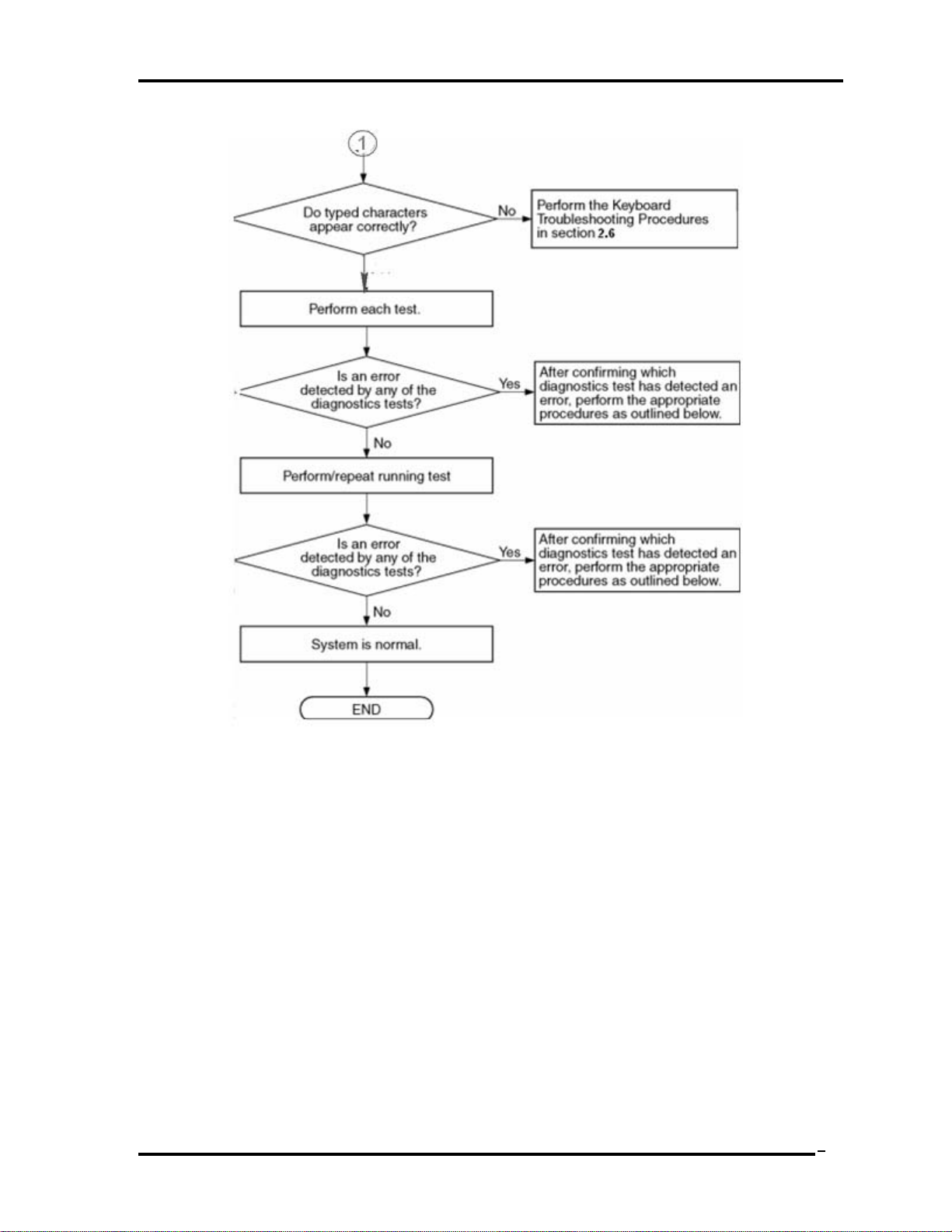
Figure 2-2-1 Troubleshooting flowchart (2/2)
If the diagnostics program cannot detect an error, the problem may be intermittent. The Test
program should be executed several times to isolate the problem. Check the Log Utilities
function to confirm which diagnostic test detected an error(s), and then perform the
appropriate troubleshooting procedures as follows:
1. If an error is detected on the system test, memory test, display test, expansion test,
real timer test, sound test or LAN/Bluetooth test, perform the System Board
Troubleshooting Procedures in Section 2.4.
2. If an error is detected on the hard disk test, perform the HDD Troubleshooting
Procedures in Section 2.5.
3. If an error is found on the keyboard test (DIAGNOSTICS TEST) and pressed key
display test, perform the Keyboard Troubleshooting Procedures in Section 2.6.
Satellite L730/Satellite 735/Satellite Pro 730 Maintenance Manual (960-Q08)
4

Chapter 2 Troubleshooting Procedures
4. If an error is found on the touch pad test, perform the Touch pad Troubleshooting
Procedures in Section 2.7.
5. If an error is detected on the display test, perform the Display Troubleshooting
Procedures in Section 2.8.
6. If an error is detected on the LAN test, perform the LAN Troubleshooting Procedures
in Section 2.9.
7. If an error is detected on the Wireless LAN, BLUETOOTH test, perform the Wireless
LAN and BLUETOOTH Troubleshooting Procedures in Section 2.10.
8. If an error is detected on the sound test, perform the Sound Troubleshooting
Procedures in Section 2.11.
9. If an error is detected on the ODD test, perform the ODD Troubleshooting Procedures
in Section 2.12.
10. If an error is detected on the HDMI test, perform the HDMI Troubleshooting
Procedures in Section 2.13
Satellite L730/Satellite 735/Satellite Pro 730 Maintenance Manual (960-Q08)
5
Chapter 2 Troubleshooting Procedures
6
2.3 Power Supply Troubleshooting
The power supply controller controls many functions and components. To determine if the
power supply is functioning properly, start with Procedure 1 and continue with the other
Procedures as instructed. The procedures described in this section are:
Procedure 1: Power Status Check
Procedure 2: Connection Check
Procedure 3: Charging Check
Procedure 4: Replacement Check
Procedure 1 Power Status Check
The following LED indicates the power supply status:
Battery LED
DC IN LED
The Power Supply control displays the power supply status with the Battery LED and the DC
IN LED as listed in the tables below.
Battery icon Power supply status
Lights Orange Battery is charged and the AC adapter is connected. It has
no relation with ON/OFF of the system power.
Lights Green Battery is fully charged and the AC adapter is connected. It
has no relation with ON/OFF of the system power.
Blinks Orange
(even intervals)
Doesn’t light Any condition other than those above.
The battery level is low while the system power is ON.
Table 2-3-1 Battery icon
DC IN icon Power supply status
Lights Green DC power is being supplied from the AC adapter.
Blinks Orange Power supply malfunction*1
Doesn’t light Any condition other than those above.
Table 2-3-2 DC IN icon
Satellite L730/Satellite 735/Satellite Pro 730 Maintenance Manual (960-Q08)
 Loading...