

Page 1

Rev 051115
Programmable Controllers
Ethernet Setup for the S2T
Ethernet communications with the S2T CPU is done through the GEN651A Ethernet module.
Prior to using this module, it must be configured using the EtherSetup_E setup software. The
EtherSetup_E software is used to configure the network parameters (IP Address, Subnet
Mask, and Multicast Addresses) in the GEN651A Ethernet module. When all the following
setup steps described below are completed, Ethernet connection to the S2T through the
GEN651A Ethernet module will be possible. There are two methods of connection:
● T-PDS (Toshiba Program Development Software). ● UDP/IP Socket Interface.
Setup GEN651 Ethernet Module
This module must be setup 1st before either of the connections methods are possible.
1, Install the EtherSetup_E software on an MS Windows computer. See the installation
instructions in the User’s Guide for the Ethernet Module Parameter Setting Tool, 6F8C1103.
2, Set the network parameters in the GEN651A module.
2.1 Set the DIP switches on the front of the EN6651A to enable setting the network
parameters from the EtherSet_E. Set DIP Switches 7 & 8 to ON (Note: 7 & 8 are the top
two switches).
2.2 Mount the EN651A on the S2T rack, then turn on power.
2.3 Connect PC and EN6651A with the V-Tool cable (standard RS232C cross cable).
2.4 Run the EtherSet_E software on the PC.
2.5 Click the Read button on the EtherSetup_E screen. The current settings are read from
the GEN651A and are displayed on the screen.
On reading a module for the
st
time, settings will appear as
1
shown to the left.
Page 2
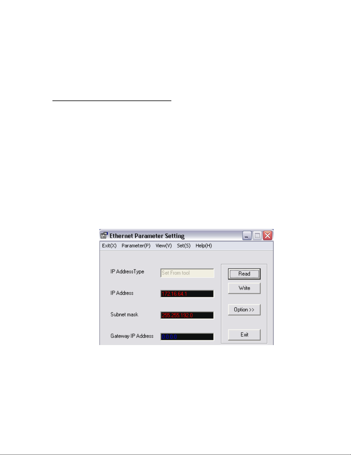
2.6 Click the Option button. Set the required parameters, then click the Write button to
write into GEN651A module.
2.7 Close the EtherSetup_E software. DIP Switches 7 and 8 must be left in the ON position
for T-PDS to work through the GEN651A module.
2.8 Cycle Power on the GEN651A module.
The new IP address will not be valid until
power is cycled on the module.
This completes setup of the GEN651A Ethernet module. If the EtherSetup_E can not establish
communications with the GEN651A, please make sure:
1. The computer is connected directly to the GEN651A using as RS232 cross cable.
2. The EtherSetup_E software is using the correct Com Port setting.
3. No other computer software is running that uses the computer’s RS232 port.
T-PDS Setup
In addition to setting up the Ethernet module, network parameters must be setup in two
additional places; the computer’s Ethernet card and the T-PDS software.
Assume the following settings were made in the EN651A Ethernet module with the
EtherSetup_E software.
Page 2
Page 3
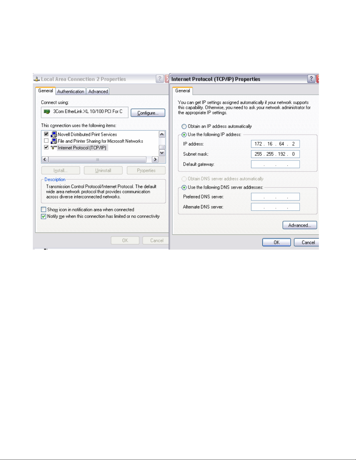
Computer Ethernet Card Setup: The computer’s Ethernet card must be setup first. Go to
the Control Panel and double click on Network Connections. Find the Ethernet card, alternate
click on it and then click on Properties.
Note that the IP Address and Subnet Mast must be the same as set in T-PDS & the GEN651A
(the last digit of the IP Address must be different however, it cannot be .1 The address
of the GEN651A module is 172. 16.64.1 ). Click OK. In case of difficulty setting up the
computer Ethernet card, contact the company MIS/IT Department.
Page 3
Page 4

T-PDS Setup: In T-PDS under the Option Menu, select Communications. Set as follows:
Using T-PDS, set the following in special register SW63:
This setting can also be made
in the ladder logic with a MOV
instruction.
This completes the T-PDS setup. T-PDS can now be connected to the S2E via Ethernet
through the GEN651A Ethernet module.
Note: If an attempt is made to assign an IP address in T-PDS before the computer’s Ethernet
card is assigned a corresponding IP address, then T-PDS will return a Win Socket error.
Page 4
Page 5

UDP/IP Socket Interface:
To use UDP/IP transmission, it is necessary to create a small program in the S2T. The
program will utilize the SEND and RECV instructions. The general procedure is as follows:
1. Execute UDP socket open: The Specified Port number must be different from the Port
number for T-PDS connection. If the Port number for T-PDS is 2000, the Port number for
UDP socket must be other than 2000 to 2002. It is recommended that 2 UDP sockets be
opened. One for data send and one for data receive respectively.
2. Execute UDP send and/or UDP receive to exchange data via Ethernet.
3. UDP socket close.
The instruction information on these functions is shown as follows.
UDP Socket Open: SEND instruction is used. ▬[ A SEND B ]▬.
A: H3100 (fixed) B: Result status
A+1: UDP open command (H0031) B+1: Error code
A+2: Socket number (1 to 12)
A+3: UDP Port number
Sample Program
12544 = H3100
49 = H0031
Socket number =1
Port number = 4000
When R0620 is set to ON, the UDP open operation is executed. When the operation is finished
R0620 is reset to OFF automatically.
Page 5
Page 6

UDP Send: SEND instruction is used. ▬[ A SEND B ]▬
A: H3100 (fixed) B: Result status
A+1: UDP send command (H0032) B+1: Error code
A+2: Socket number (1 to 12)
A+3: Receiver IP address (note 1)
A+4: Ditto
A+5: Receiver Port number
A+6: Transmit data word size (1 to 1000)
A+7: Source data table register type (note 2)
A+8: Source data table register starting address
Note 1
If receiver IP address is 192.0.0.5 (HC0.0.0.5), set as follows.
A+3 = H0005
A+4 = HC000
Note 2
RW register = 3
D register = 4
Sample Program
12544 = H3100
50 = H0032
Socket number = 1
Receiver IP address = 192.0.0.5 (-16384 = HC000)
Receiver Port number = 4000
Transmit ward size = 200
Source data table is D1000 and after
When R0622 is set to ON, 200 data words D1000 to D1199 are transmitted to the destination
(IP address = 192.0.0.5, Port number = 4000). When the operation is finished, R0622 is reset
to OFF automatically.
Page 6
Page 7

UDP Receive: RECV instruction is used, ▬[ A RECV B ]▬
A: H3100 (fixed) B: Result status
A+1: UDP receive command (H0033) B+1: Error code
A+2: Socket number (1 to 12)
A+3: Sender IP address (note 1)
A+4: Ditto
A+5: Sender Port number
A+6: Receive data word size (1 to 1000)
A+7: Destination data table register type (note 2)
A+8: Destination data table register starting address
A+9: Timeout setting (0.1s units, see note 3)
Note 1: If sender IP address is 192.0.0.5 (HC0.0.0.5), set as follows.
A+3 = H0005
A+4 = HC000
For broadcast receiving, set 0.0.0.0.
Note 2:
RW register = 3
D register = 4
Note 3: If A+9 = 0, there is no timeout.
Sample program
12544 = H3100
51 = H0033
Socket number = 2
Sender IP address = 192.0.0.5 (-16384 = HC000)
Sender Port number = 5000
Receive word size = 100
Destination data table is D2000 and after, no timeout setting
Page 7
Page 8

When R0621 is set to ON, 100 data words are received from the sender (IP address =
192.0.0.5, Port number = 5000) and are stored in D2000 to D2099. When the operation is
finished, R0621 is reset to OFF automatically.
UDP Socket Close SEND instruction is used. [ A SEND B ]▬
A: H3100 (fixed) B: Result status
A+1: UDP close command (H0034) B+1: Error code
A+2: Socket number (1 to 12)
Sample program
12544 = H3100
52 = H0034
Socket number =1
When R0623 is set to ON, the UDP socket is closed. When the operation is finished, R0623 is
reset to OFF automatically.
Page 8
 Loading...