

Page 1
Page 2
TOSHIBA
1.
2.
*N*ROD”CT[ON
GENERA,, SpECIF~CAT]ON
2.1
Rat,& Performance
2.2
Functions
2.3
Pr,ot~tion Curves
........................................................
................................................
..............................................
......................................................
..............................................
6F9EOlll
CONTENTS
Page
-j-
3
4
5
17
3.
APPEARANCE AND CONFIGURATION
3.1
SZEZl-ClA*
3.2
S2.E21-ClA[
4.
MODNTlNO
4.1
AND CONNECTION
MolJnting
4.2 Co~yj&ion
HANDLING
5.
lnijtal1 ing Battery
5.1
5.2 Turning Power On
(without
1 (with
.......................................................
.....................................................
............................................................
...............................................
5.3 Basic Operation of Screen
5.4 Registration of
5.5 Menu
...........................................................
5.6 Measurement
5.7 Event
5.8 Setting
5.9 Testing
5.10
Failure
..........................................................
........................................................
........................................................
Information
ID
....................................................
5.11 Hand1 ing of Memory Card
5.12 Directional Ground Unit
6.
MAINTENANCE AND INSPECTION
6.1 Periodic Inspection
6.2
6.3
Troubleshooting
Berlch Test
.................................................
......................................................
........................................
.......................................
DG)
........................................
DG)
.............................................
..........................
......................................
.............................................
............................................
........................................
(DG)
..........................................
............................................
:.
.................
...................................
18
18
21
27
27
30
38
38
38
39
44
46
47
54
56
81
83
86
91
92
92
96
I,,,,
7.
PROTECTIVE DETECTION SCHEME
7.1 Overload Unit
7.2
Locfked Rotor hit
Reptitive
7.3
..................................................
...........................
Starting
.........................................
.............................................
7.4 Detection of Starting Current and Starting Time
...............
..-.c
.................
105
105
109
113
114
7.5 Detection of the Heating Time Constant and
Cocli
ing Time Constant
7.6 Setting Based on Fundamental Information
Setting For Reduce Voltage Starting .............................
7.7
APPENDIX A
Rev
2
2
g
>
. . . . . . . . . . . . . . . . . . . . . . . . . . . . . . . . . . . . . . . . . . . . . . . . . . . . . . . . . .
1
TYPE
S2E21-ClAU
...........................................
........................
VERSION 1.01
115
117
120
121
-l-
Page 3

TOSHIBA
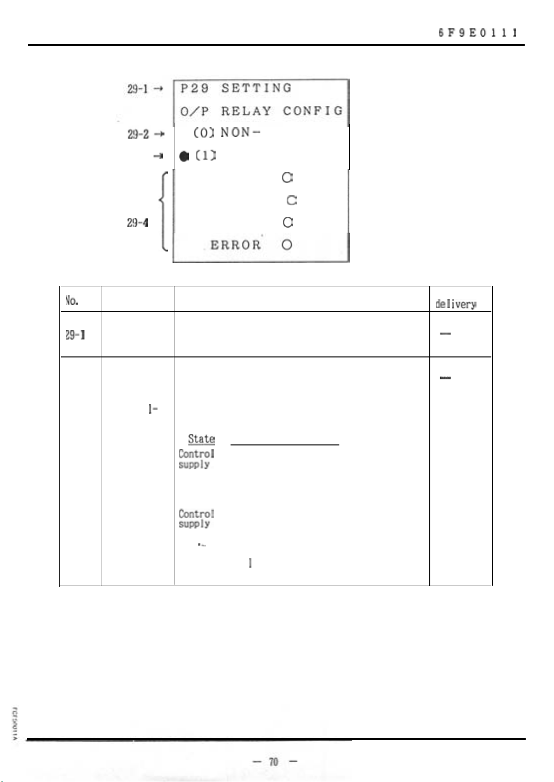
29-3
--)
0
(0) NON-
0 (1)
FAIL-SAFE
6F9EOlll
FAIL-SAFE
VO.
29-l
29-2
TRIP
ALARM
2!J-4
i
Item
Setting
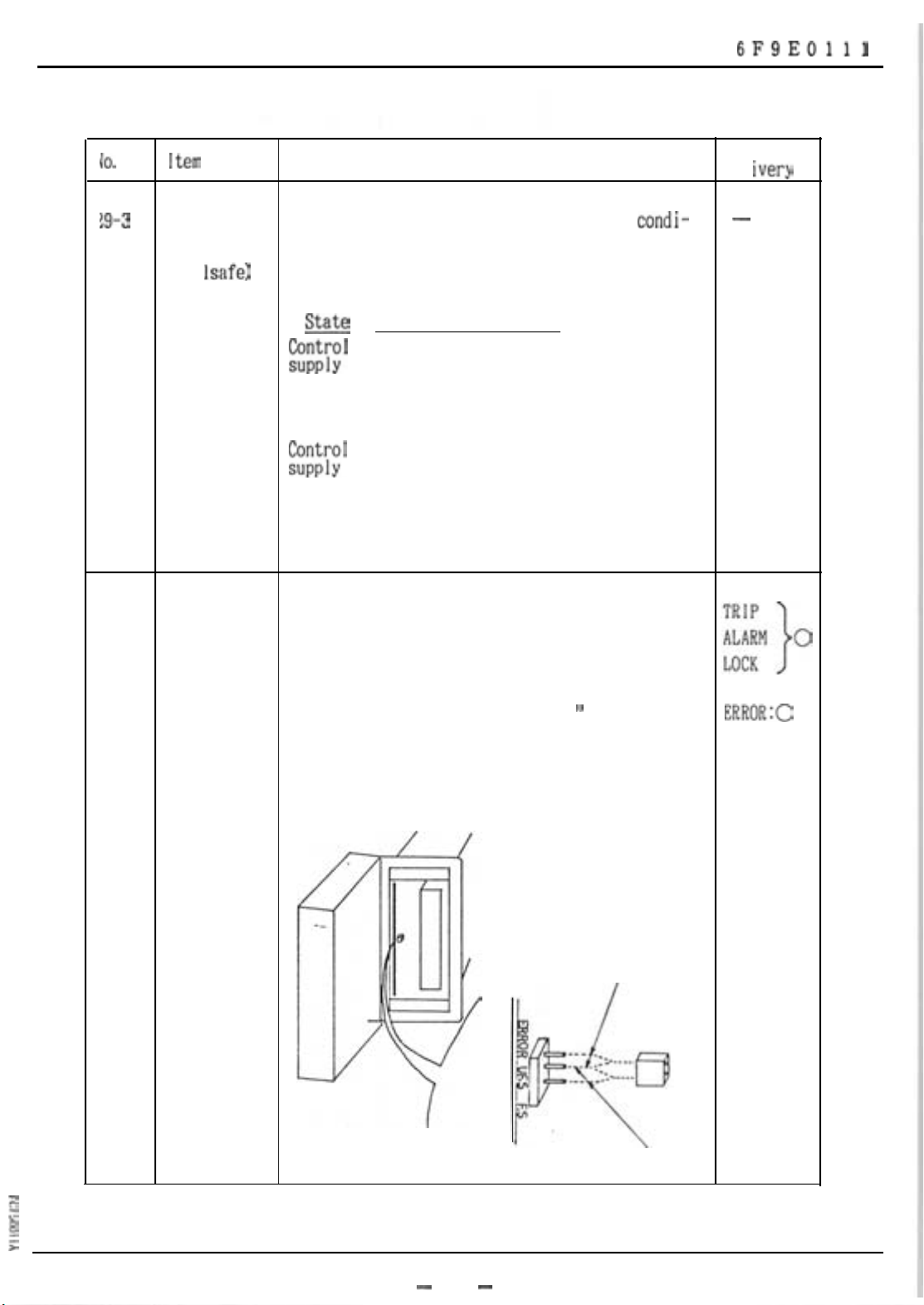
Energized-on The output relay is energized on operation.
operation
(Non-fai
safe)
Description
Sets the operation mode of the output relay.
The state of output contact is shown below in
I-
the case of tripping.
E$r;’
not
provided
State
LOCK
a-contact b-contact
Open Closed
0
0
0
State at
de1 ivery
-
-
:%;’
provided
.-
Trip
Open Closed
C 1 osed Open
Page 4
TOSHIBA
6F9EOlll
i0.
29-3
!9-4
Item
Description
Continuously The output relay is energized at normal
energized
(fai
Isafe)
tion. The state of output contact is shown below
in the case of tripping.
m
a-contact b-contact
Open Closed
t%;’
not
provided
Closed
Open
&$;’
provided
Setting
Trip
Selects between continuously energized and
Open Closed
energized-on-operation for 3 outputs-trip.
alarm, and lock.
Setting is made by moving the cursor to this
position and entering “0” or “1.
‘*
condi-
State at
de I ivery
-
ERROR:0
The setting of the error output is made in
hardware.
Non-fail-safe
fail-safe
-
71
-
Page 5
TOSHIBA
30-l +
P30
SETTING
RY O/P SEL.
- (01 NOPi.&
E%
-
UC
INST
UB
g
- -
6F9EOlll
;;;.
+
0
30-3
D-1
&2
30-3 A
Item
jetting
\larm
output
SPARE1
-
SPARE2
m
-
Description
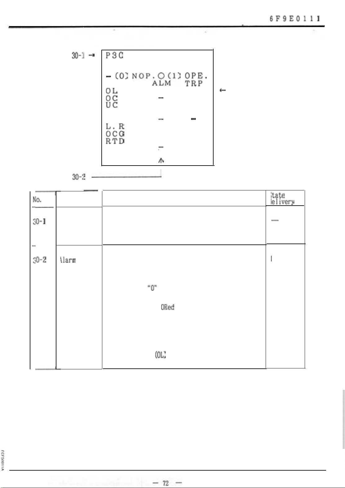
Sets the operation condition for the output
relay.
Selects a unit that drives the alarm output
relay when an alarm is detected.
Enter either
The output is an
from the unit that drives the alarm output
relay.
"0"
(not operate) or "1" (operate).
ORed
output of alarm detections
Zate at
leiivery
I
Locked-rotor has no alarm. But it isdetected
as an overload
(OL)
alarm instead.
Page 6
TOSHIBA
6F9EOlll
No.
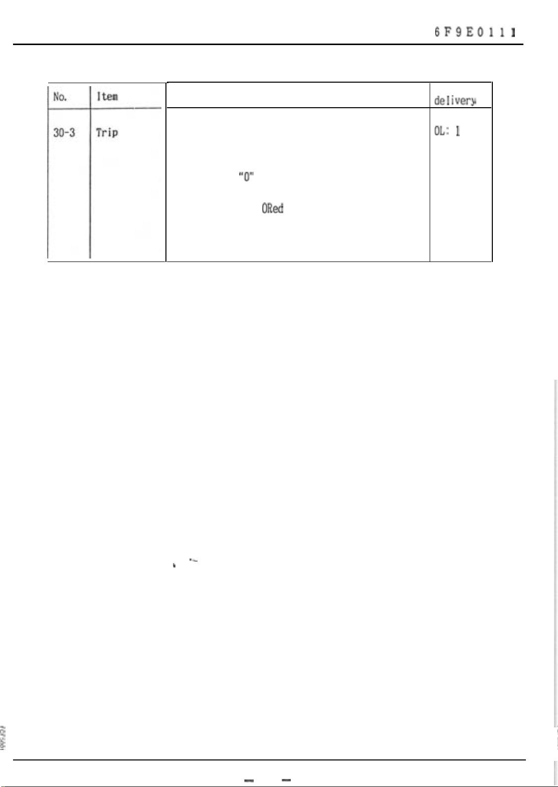
30-3
item
Trip
Description
Specifies a unit that drives the trip output
relay when a trip is detected.
Enter either
The output is an
from the unit that drives the trip output
relay.
I-
“0”
(not operate) or “1” (operate).
ORed
output of trip detections
State at
de1 ivery
OL: 1
Others:
--
.
-
13
-
Page 7

TOSHIBA
6F9EOlll
No.
31-1
31-1
--t
31-2 ‘+
I tern
Setting
P31 SETTING
ATD O/P = 2
“1’14;”
2=IS
3=IT
4=IAV
5=es
6=8R
Description
Selects an analog transducer output.
7=RTDl
8=RTD2
9=RTD3
1
O=RTD4
ll=RTD5
12=RTD6
13=RTD7
14=RTD8
.15=10
>
State at
delivery
-
31-2
transducer
output
Ana I og
transdwer
output
IR
IS
IT
IAV
8.3
BR
Selects a measuring unit that outputs data to
the analog transducer.
I
4mA -
0
A
‘or
CT RATIO
I
0°C - BSM
oc
-
20
mA
(No.20-2)
(No. 21-6)
200
"C
transducer
xltput
RTDl
RTD2
RTD3
RTD4
RTD5
RTD6
RTDt?
10
-2o'c -
4mA
OA
0
-
-
20
mA
2OO'C
ZCT RATIO
(No.20-3)
-
14
-
Page 8
TOSHIBA
32-2
6F9EOlll
+
Kind of RTD
EE
:
RTD7
RTD8
:
(O=OFF
l=PtlooQ
2=PtlOOQ:JIS
3=Ni
4=Ni 12062
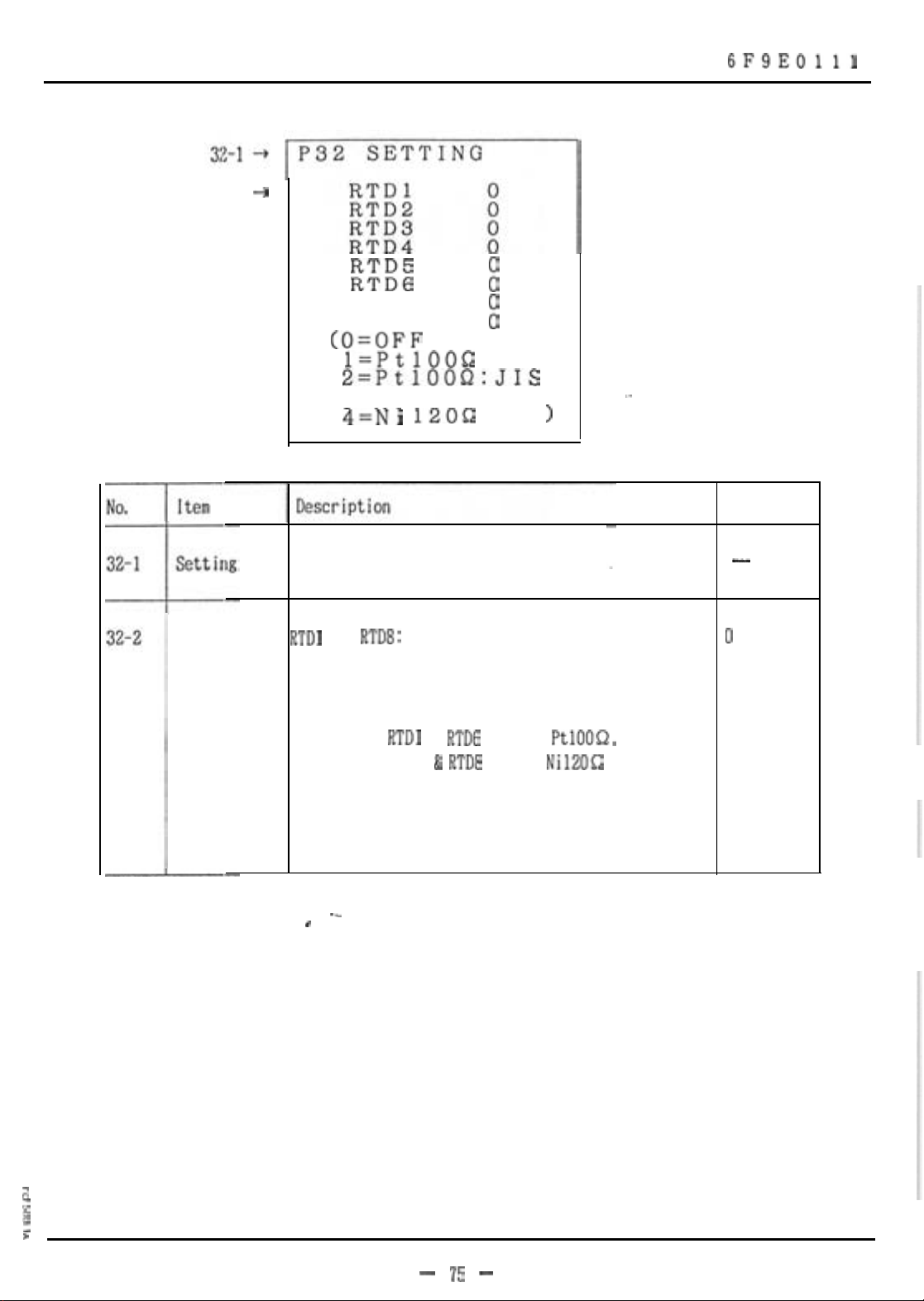
Sets the kind of RTD.
RTDl
to
type. Different RTD types can be selected on
one relay.
Example:
10062
RTD8:
Selects the corresponding RTD
RTDl
to
RTDG
can be
RTD? &
individual relay.
RTDB
can be
>
PtlOOQ,
Nil2062
-.
and
on one
State at
delivery
-
0
Set to 0 (OFF) those channels that are not used.
--
.
z
g
I
>
- 75 -
Page 9
TOSHIBA
6F9EOlll
No.
33-l
33-1
33-2
Item Description
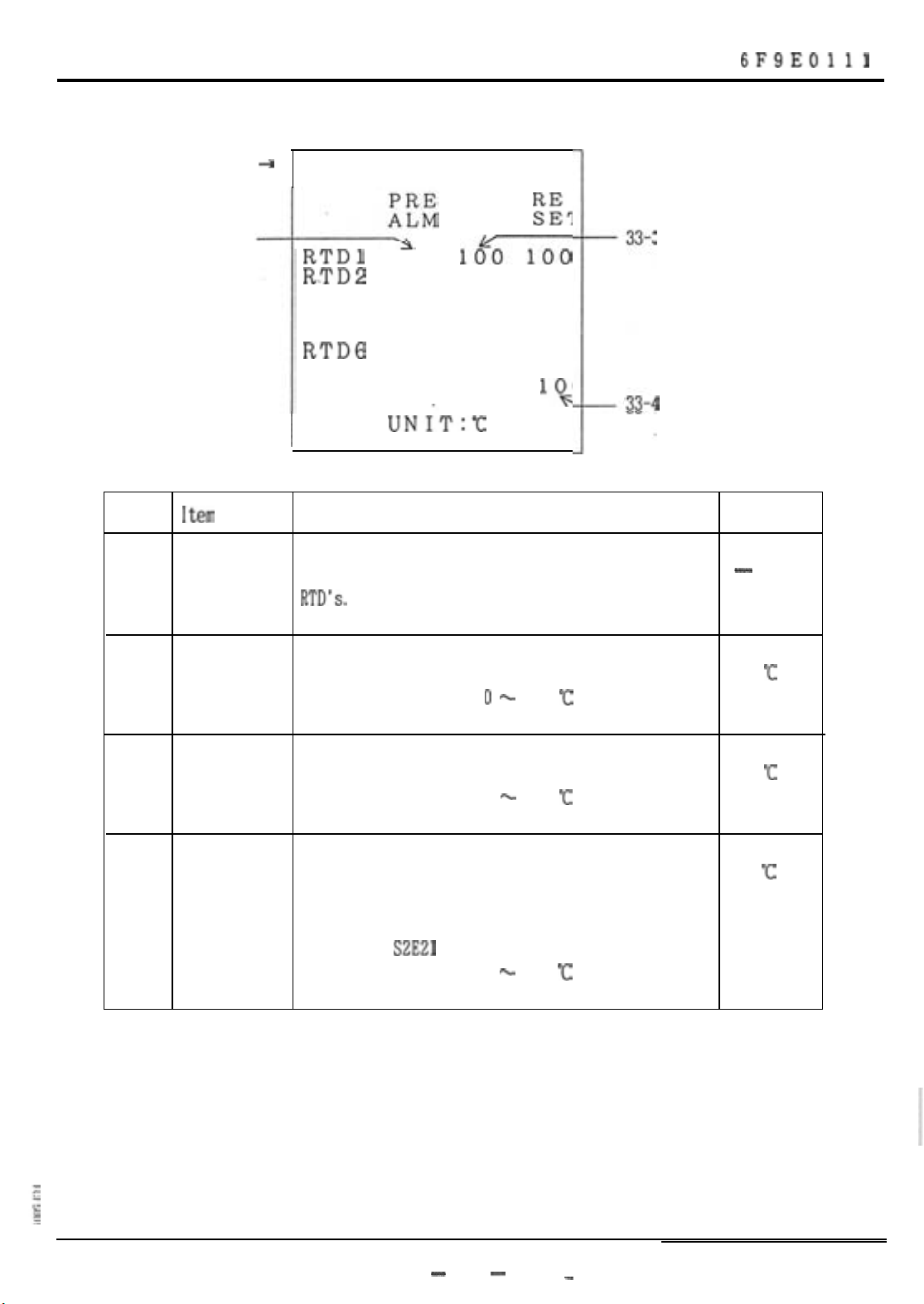
Setting Sets the alarm, trip and reset levels for the
P33 SETTING
+
TRP
RTDl
R.TD2
RTD3
RTD4 100 100 100
RTD5
RTDG
RTD7
RTD8
100
100 100 100
100 100 100
100 100 100
100 100 100
100 100 100
100 100
UNIT:C
10%
I
RTD's.
ti%T
33-3
102
.33-4
1.
State at
delivery
-
33-2
33-3 Trip level
33-4
Alarm level Sets alarm detection temperature for each RTD.
Reset level Sets a reset temperature for each RTD. 100
100
'C
Setting range: 0 - 200
Sets trip detection temperature for each RTD.
Setting range: 0 - 200
After the temperature goes below the reset
level. the S2E21 can then be reset.
Setting range: 0 - 200
'c
"c
C
100
'c
'c
-
76
-
-
Page 10
TOSHIBA
6F9EOlll
lo.
34-l
34-1
34-Z --)
34-3
34-4
34-5
I
tern
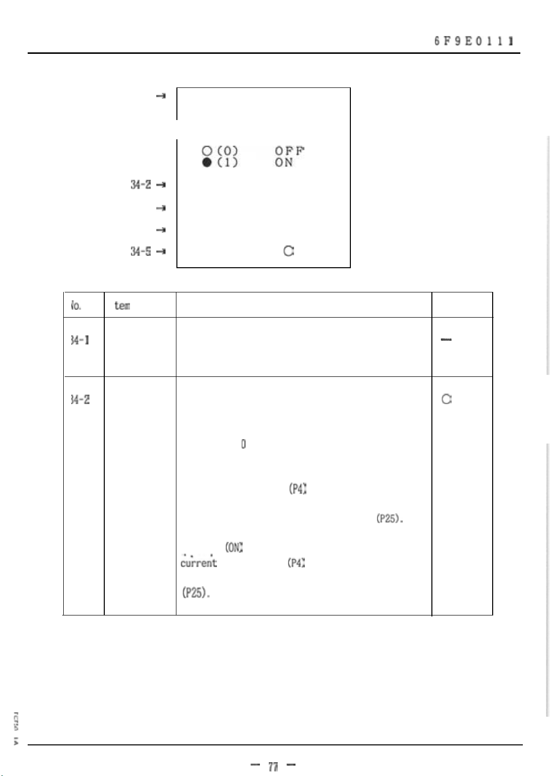
Setting Sets whether or not automatic detection is
P34 SETTING
+
*AUTO LEARNING*
1st
--t
+
+
Description
needed.
Tst 0
TR 0
TD
0
0
State at
de I i very
-
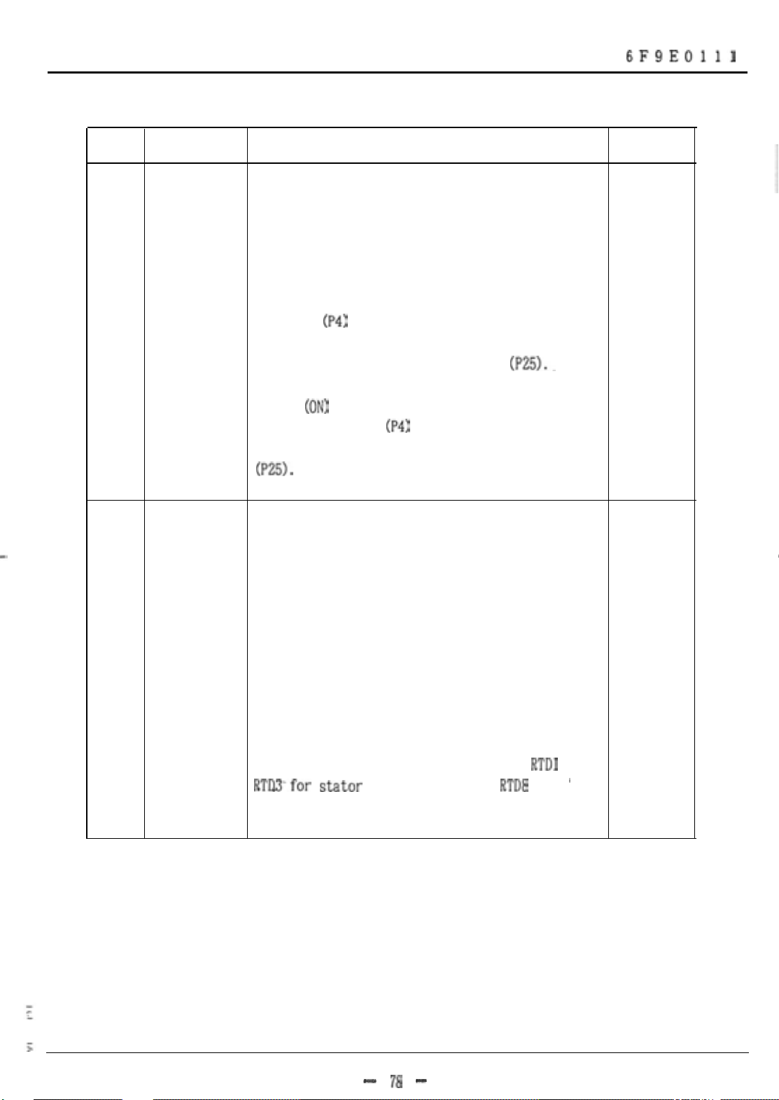
34-2
Starting Automatically detects the starting current and
current
specifies whether or not the detected value is
taken as the starting current setting.
Enter either 0 (OFF) or 1 (ON).
When 0 (OFF) is entered, the detected starting
current is displayed
not the detected value, is used as the setting
value in the starting current setting
When 1
d&rent
setting value in the starting current setting
(P25).
(ON)
is entered, the detected starting
is displayed
(P4)
but the input value,
(P25).
(P4)
and also taken as the
0
$
z
3
i
- 17 -
Page 11
TOSHIBA
6F9EOlll
No.
34-3
34-4
Item
starting
time
Heating time Automatically detects the heating time constant
constant
Description
Automatically detects the starting time and
specifies whether or not the detected starting
time is used as the setting value.
Enter either 0 (OFF) or 1 (ON).
When 0 (OFF) is entered, the starting time is
displayed
not the detected value, is used as the-setting
value in the starting time setting
When 1
time is displayed
setting value in the starting time setting
(P25).
and specifies whether or not the detected value
is taken as the heating time constant setting.
(P4)
but the input setting value;
(P25)..
(ON)
is entered, the detected starting
(P4)
and also taken as the
State at
delivery
0
0
When 1 (ON) is entered, the heating time
constant is automatically detected and the
detected value is taken as the setting value.
Upon completion of detection, this setting
automatically turns off.
Automatic detection requires input of
RTDPfor
ambient temperature.
stator
temperature, and
RTD8
RTDl
to
for
'
- 18 -
Page 12
TOSHIBA
6F9EOlll
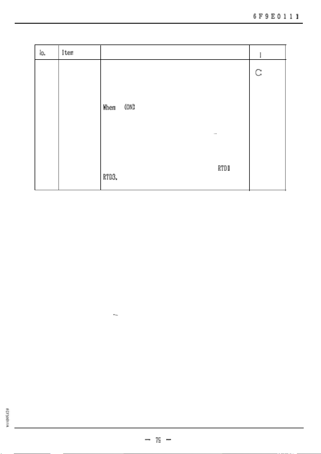
IO.
14-5
Item
Description
Cooling time Automatically detects the cooling time constant
constant
and specifies whether or not the detected value
is taken as the cooling time constant setting.
When
1
(ON)
is entered, the cooling time
constant is automatically detected and the
detected value is taken as the setting value.
.-
Upon completion of detection, this setting
automatically turns off.
Automatic detection requires input of
RTD3.
and RTD8 for ambient temperature.
RTDl
to
State at
de 1 i very
0
--
- 19 -
Page 13
TOSHIBA
6F9EOlll
I
UO.
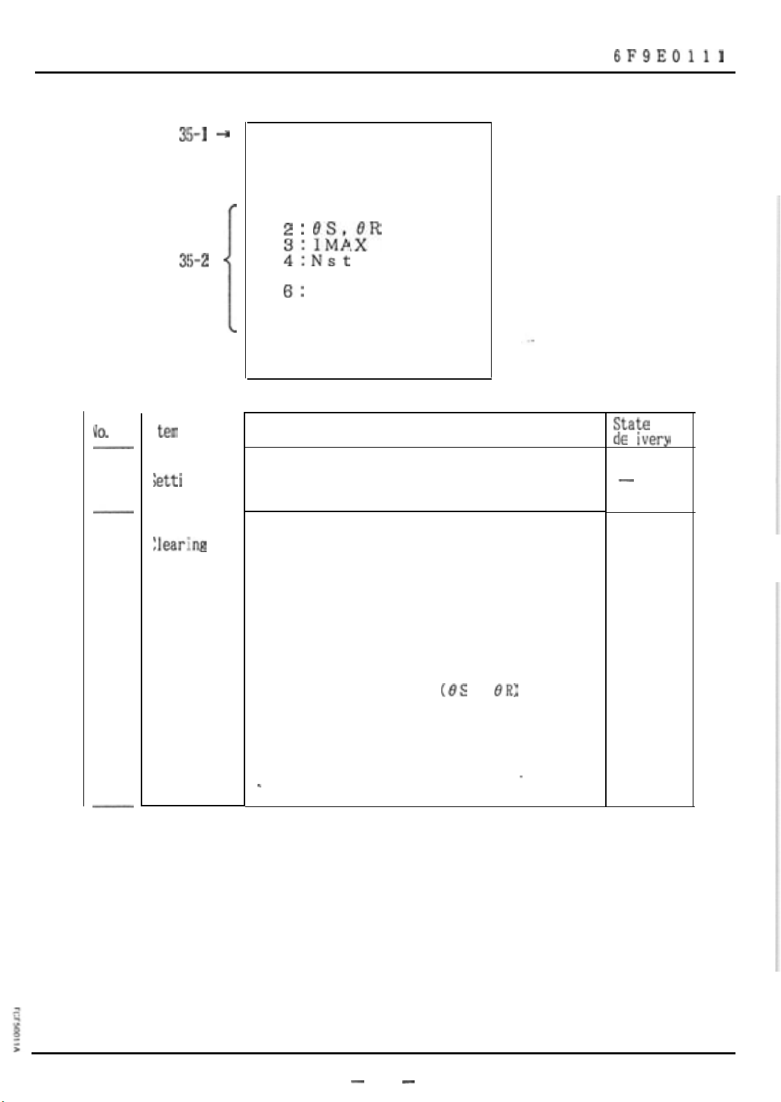
35-1
3!i-1 --)
P35 SETTING
Clear data 0
(1 : ALL
: : ELii”
3!+2
4iNst
5:Ttrun
6:
7 : LEARNED TD
1
8 : MAX STARTS)
-:
tern
Description
--
Iett i
ng
Clears accumulated data and held data.
--
LEARNED TR
itate
le
I ivery
-
at
35-2
:lear:ing
Entering the numbers of items whose data you
want cleared causes the corresponding data to be
cleared.
Example:
1. Data may be required to be reset (cleared)
due to a new motor installation.
2. Temperature data only
(0.3
or
OR)
may be
required to be reset for an emergency
restart. Caution should be taken in
resetting this data. Motor damage may
_
--
result.
-
-
80
-
Page 14

TOSHIBA
5.9 Testing
I
UO.
--
1 tern
M-1
110-2
40-3 +
P40
+
*
*o/p*
Description
TESTING
I/P*
RESET
SPARE1
SPARE2
ATD 4
(4-2
0
:
mA
OmA)
6F9EOlll
Zate
at
le
I ivery
10-I
10-2
Testing
Input
Perform tests on the input/output circuit.
Displays the state of contact input from the
terminal block.
Displays 0 when there is an input: and
Displays 0 when there is no input.
The 3-phase input and zero-phase input are
checked with the current value displayed on P2.
--
^ --
-
-
-
81
-
Page 15

TOSHIBA
6F9EOlll
Description
Changes the outpit of the analog transduser.
Press
a current value
analog transducer.
The output current is checked externally.
[EXE1
key. The cursor appears, and enter
(4-20 mA)
to be output from the
State at
delivery
.-
-
-
82
-
Page 16
TOSHIBA
5.10 Failure Information
6F9EOlll
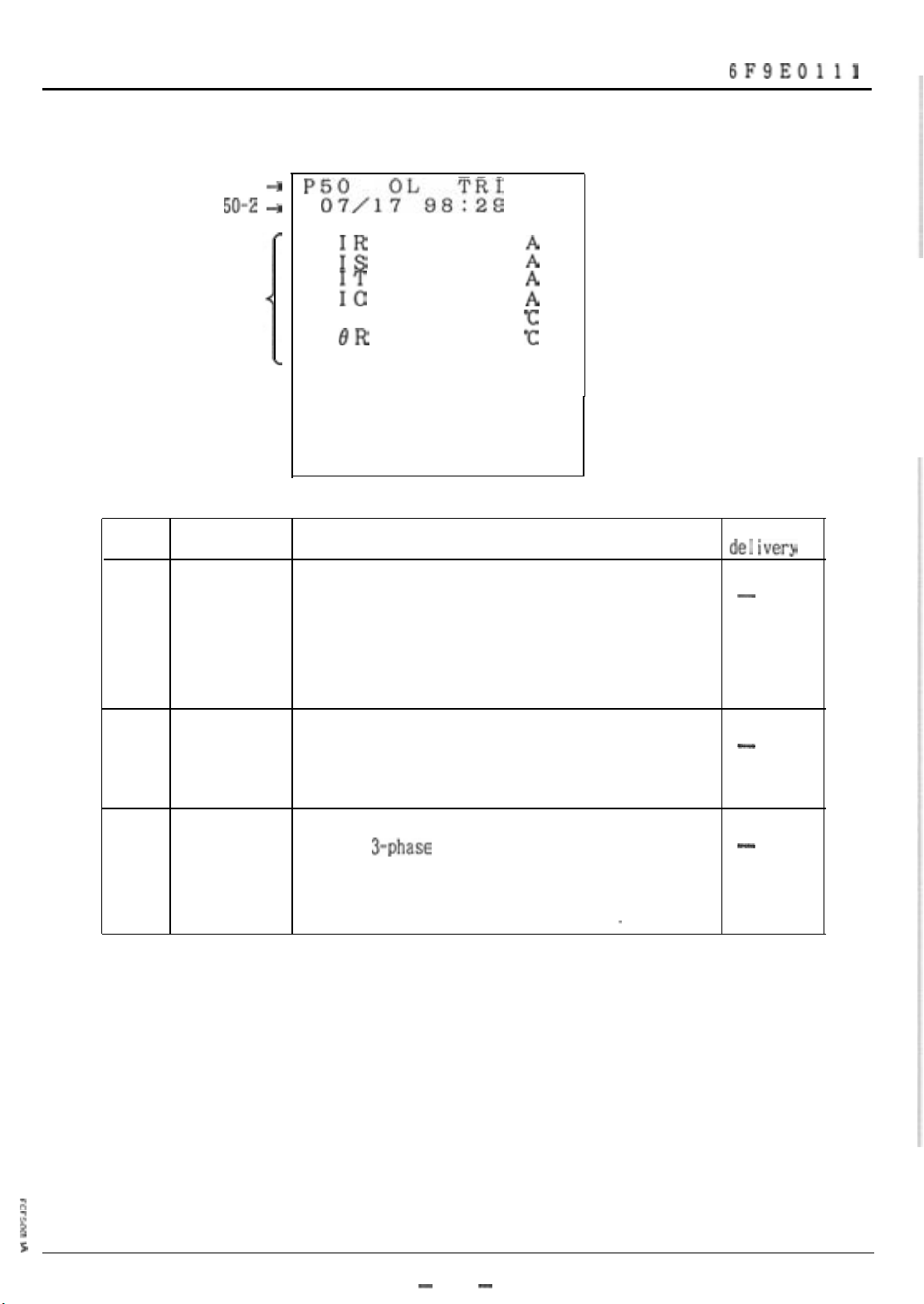
No.
50-l
50-l
50-Z
50-3
Item
Trip
information
+ P50
-3
07dL88:28
:z
128 130
::
132 0
TRIP
2
2
es 60.0
BR
23.2
UB 2%
Description
Displays information at the date and time of the
latest current-associated trip.
:
State at
de1 ivery
-
50-2
50-3
Cause of trip is displayed.
Time
Dispiayes the date and time at which the trip
occurred.
information Displays
temperature rise and unbalance factor at the
trip.
--
3-phase
current. zero-phase current,
-
-
-
:
$
I:
>
-
83
-
Page 17
TOSHIBA
6F9EOlll
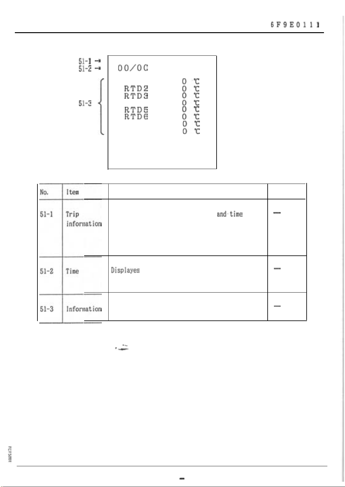
5:1-1 +
5:1-z +
5:1-3
P51
oo/oo
00: 00
TRIP
RTD 1
::
Ez
RTD4
::
RTD5
RTDG
E
RTD7
RTD8
E
Description
Displays information at the date
latest trip.
and.time
of the
State at
delivery
-
RTD number. that has tripped is displayed.
Displayes
the date and time at which the trip
occurred.
Displays temperature of each RTD at trip.
--
--
-
-
- 84
-
Page 18
TOSHIBA
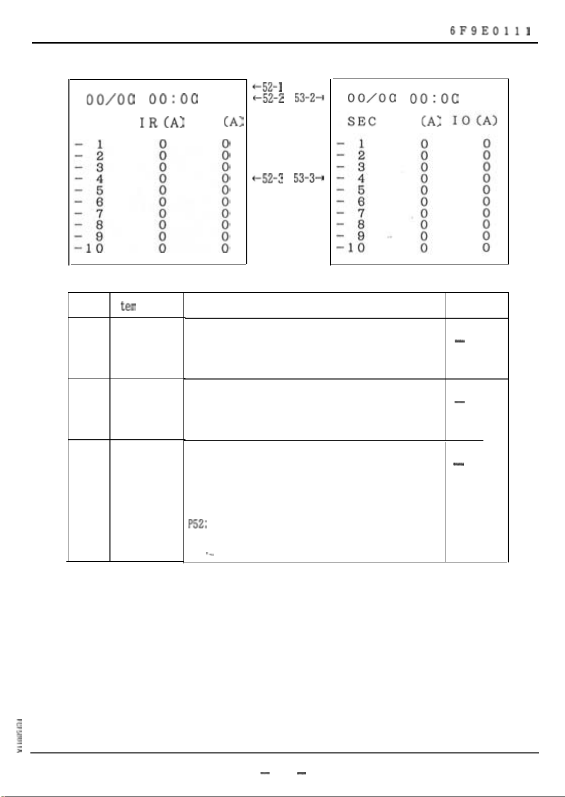
P52 TRIP CURRENT
oo/oo
0o:oo
+52-l
53-1-r
~52-2 53-2+
6F9EOlll
P53 TRIP CURRENT
oo/oo
0o:oo
SEC
No.
52-1
53-l
52-2
53-2
IR(A)
I
tern
Trip current
trend
Time
IS
(A)
IT
(A)
-52-3 53-3-9
Description
Displays the current trend immediately before
the trip
Displays the date time at which the trip
occurred.
State at
delivery
-
-
52-3
53-3
Current
trend
Displays 10 seconds of 1 second interval current
trend before trip.
Current of R-phase and S-phase are displayed on
P52:
and current of T-phase and zero-phase are
displayed on P53.
-_
-
-
85
-
Page 19
TOSHIBA
6F9EOlll
5.11 Handling of
The
SZE21s
Hemory
Card
each have a dedicated memory card, which is used for backup of
S2E21
settings and as information media for the monitor system (purchased separately)
that includes personal computers.
The specifications of the memory card are
shown in Table 5.
5.11.1 Sack up of Setting
The memory card is utilized as a backup of the setting of
the.S2E21.
Procedure for backup
1.
Cancel the write-pretect for the
&x
5.11.3
2.
Insert the memory card into the
&I:
5.11.3
Initialize the memory card.
3.
(See
5.8 P27.
(2j.j
(3). )
)
memory
S2E21.
card.
4.
Store the contents of setting into the memory card.
See
5.8 P27.
5.
Turn on the write-protect for the memory card.
Gef!
5.11.3
)
(2j.j
The memory card uses S-RAM card with a battery backup that prevents the contents
of the backup from being lost when you pull the memory card from the
S2E21.
The battery backup also allows the memory card to be inserted or withdrawn during
the operation of the
S@l.
---
CAUTION: Removing the memory card from the
S2E21
and storing it alone may result
in the loss of the backed-up contents when the backup battery is
exhausted.
The memory card must be left inserted in the
S2E21.
$
g
:
-
86
-
Page 20
TOSHIBA
Procedure for loading the backed-up settings of the memory card into the SZE21.
6F9EOlll
Register the MACH. ID and PASS ID of the
1.
(MACH. ID and PASS ID must be the same as those when the settings were
backed up in the memory card.)
(See 5.3.3. 5.4.)
Insert the memory card into the
2.
(See 5.11.3
3.
Load the backed-up contents from the memory card into the S2E21.
The contents of settings backed up by the memory card are those stored by the
above backup procedure.
the contents of the memory card do not automatically change.
to perform the store operation again.
Prior to the loading of the backed-up settings, comparison is made of the
MACH. ID and PASS ID between the memory card and the S2E21.
numbers do not agree, the backed-up settings will not be loaded into the S2E21.
5.11.2 Memory Card As Information Media
(3j.j
After this, when the settings of the S2E21 are changed,
S2E21.
S2E21.
You are reguired
When these ID
The memory card may be used as information media for the monitor system including
personal computers and for the
For detail, see the manual for the monitor system.
S2E21.
-
87
-
Page 21
TOSHIBA
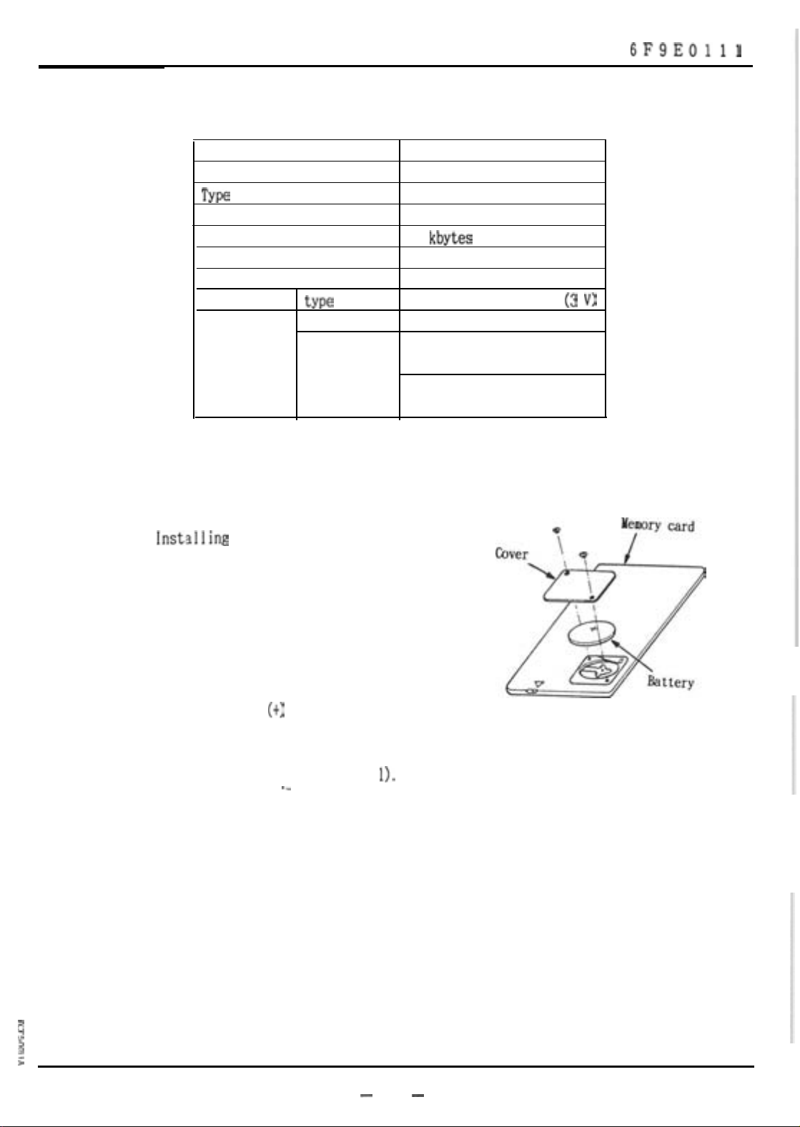
Table 4 Memory Card Specifications
Item Description
Manufacturer Toshiba
Type
Memory type
Capacity
Scheme Memory bus scheme
Pin number 40 pins
Battery
Battery life Not in relay Approx. 2 years
5.11.3 Handling of Memory Card
MCA 5101BAA
S-RAM
32
kbytes
type
Inserted
Lithium coin battery (3
Greater than 10 years
V)
in relay W/control power on relay
Approx. 2 years
W/no power to relay
6F9EOlll
The memory card should be handled as follows.
(1)
Inst,alling
1)
battery:
Open the battery holder cover of the
memory card with the screwdriver
supplied.
2)
Place the attached battery in the
battery holder, with the positive
polarity
3)
Close the battery holder cover in the
process reverse to step
(t)
facing up.
._
---
1).
_I
n
2
:
-
88
-
Page 22

TOSHIBA
(2)
Write-protecting the memory card:
The memory card is provided with a writeprotect switch for preventing inadvertent
writing. Turn on the write-protect switch
(to set the write-protect) except when
storing the data into the memory card.
To set the write-protect:
Move the write-protect switch to the right
side (to align with the
mark-7’).
This
djzjables writing into the memory card.
To cancel the write-protect:
Move the write-protect switch to the left
side (away from the mark
“V”).
This
enables writing into the memory card.
6F9EOlll
---
-_
-
89 -
Page 23
TOSHIBA
29-3
--)
0
(0) NON-
0 (1)
FAIL-SAFE
6F9EOlll
FAIL-SAFE
VO.
29-l
29-2
TRIP
ALARM
2!J-4
i
Item
Setting
Energized-on The output relay is energized on operation.
operation
(Non-fai
safe)
Description
Sets the operation mode of the output relay.
The state of output contact is shown below in
I-
the case of tripping.
E$r;’
not
provided
State
LOCK
a-contact b-contact
Open Closed
0
0
0
State at
de1 ivery
-
-
:%;’
provided
.-
Trip
Open Closed
C 1 osed Open
Page 24

TOSHIBA
6F9EOlll
i0.
29-3
!9-4
Item
Description
Continuously The output relay is energized at normal
energized
(fai
Isafe)
tion. The state of output contact is shown below
in the case of tripping.
m
a-contact b-contact
Open Closed
t%;’
not
provided
Closed
Open
&$;’
provided
Setting
Trip
Selects between continuously energized and
Open Closed
energized-on-operation for 3 outputs-trip.
alarm, and lock.
Setting is made by moving the cursor to this
position and entering “0” or “1.
‘*
condi-
State at
de I ivery
-
ERROR:0
The setting of the error output is made in
hardware.
Non-fail-safe
fail-safe
-
71
-
Page 25

TOSHIBA
30-l +
P30
SETTING
RY O/P SEL.
- (01 NOPi.&
E%
-
UC
INST
UB
g
- -
6F9EOlll
;;;.
+
0
30-3
D-1
&2
30-3 A
Item
jetting
\larm
output
SPARE1
-
SPARE2
m
-
Description
Sets the operation condition for the output
relay.
Selects a unit that drives the alarm output
relay when an alarm is detected.
Enter either
The output is an
from the unit that drives the alarm output
relay.
"0"
(not operate) or "1" (operate).
ORed
output of alarm detections
Zate at
leiivery
I
Locked-rotor has no alarm. But it isdetected
as an overload
(OL)
alarm instead.
Page 26

TOSHIBA
6F9EOlll
No.
30-3
item
Trip
Description
Specifies a unit that drives the trip output
relay when a trip is detected.
Enter either
The output is an
from the unit that drives the trip output
relay.
I-
“0”
(not operate) or “1” (operate).
ORed
output of trip detections
State at
de1 ivery
OL: 1
Others:
--
.
-
13
-
Page 27

TOSHIBA
6F9EOlll
No.
31-1
31-1
--t
31-2 ‘+
I tern
Setting
P31 SETTING
ATD O/P = 2
“1’14;”
2=IS
3=IT
4=IAV
5=es
6=8R
Description
Selects an analog transducer output.
7=RTDl
8=RTD2
9=RTD3
1
O=RTD4
ll=RTD5
12=RTD6
13=RTD7
14=RTD8
.15=10
>
State at
delivery
-
31-2
transducer
output
Ana I og
transdwer
output
IR
IS
IT
IAV
8.3
BR
Selects a measuring unit that outputs data to
the analog transducer.
I
4mA -
0
A
‘or
CT RATIO
I
0°C - BSM
oc
-
20
mA
(No.20-2)
(No. 21-6)
200
"C
transducer
xltput
RTDl
RTD2
RTD3
RTD4
RTD5
RTD6
RTDt?
10
-2o'c -
4mA
OA
0
-
-
20
mA
2OO'C
ZCT RATIO
(No.20-3)
-
14
-
Page 28

TOSHIBA
32-2
6F9EOlll
+
Kind of RTD
EE
:
RTD7
RTD8
:
(O=OFF
l=PtlooQ
2=PtlOOQ:JIS
3=Ni
4=Ni 12062
Sets the kind of RTD.
RTDl
to
type. Different RTD types can be selected on
one relay.
Example:
10062
RTD8:
Selects the corresponding RTD
RTDl
to
RTDG
can be
RTD? &
individual relay.
RTDB
can be
>
PtlOOQ,
Nil2062
-.
and
on one
State at
delivery
-
0
Set to 0 (OFF) those channels that are not used.
--
.
z
g
I
>
- 75 -
Page 29

TOSHIBA
6F9EOlll
No.
33-l
33-1
33-2
Item Description
Setting Sets the alarm, trip and reset levels for the
P33 SETTING
+
TRP
RTDl
R.TD2
RTD3
RTD4 100 100 100
RTD5
RTDG
RTD7
RTD8
100
100 100 100
100 100 100
100 100 100
100 100 100
100 100 100
100 100
UNIT:C
10%
I
RTD's.
ti%T
33-3
102
.33-4
1.
State at
delivery
-
33-2
33-3 Trip level
33-4
Alarm level Sets alarm detection temperature for each RTD.
Reset level Sets a reset temperature for each RTD. 100
100
'C
Setting range: 0 - 200
Sets trip detection temperature for each RTD.
Setting range: 0 - 200
After the temperature goes below the reset
level. the S2E21 can then be reset.
Setting range: 0 - 200
'c
"c
C
100
'c
'c
-
76
-
-
Page 30

TOSHIBA
6F9EOlll
lo.
34-l
34-1
34-Z --)
34-3
34-4
34-5
I
tern
Setting Sets whether or not automatic detection is
P34 SETTING
+
*AUTO LEARNING*
1st
--t
+
+
Description
needed.
Tst 0
TR 0
TD
0
0
State at
de I i very
-
34-2
Starting Automatically detects the starting current and
current
specifies whether or not the detected value is
taken as the starting current setting.
Enter either 0 (OFF) or 1 (ON).
When 0 (OFF) is entered, the detected starting
current is displayed
not the detected value, is used as the setting
value in the starting current setting
When 1
d&rent
setting value in the starting current setting
(P25).
(ON)
is entered, the detected starting
is displayed
(P4)
but the input value,
(P25).
(P4)
and also taken as the
0
$
z
3
i
- 17 -
Page 31

TOSHIBA
6F9EOlll
No.
34-3
34-4
Item
starting
time
Heating time Automatically detects the heating time constant
constant
Description
Automatically detects the starting time and
specifies whether or not the detected starting
time is used as the setting value.
Enter either 0 (OFF) or 1 (ON).
When 0 (OFF) is entered, the starting time is
displayed
not the detected value, is used as the-setting
value in the starting time setting
When 1
time is displayed
setting value in the starting time setting
(P25).
and specifies whether or not the detected value
is taken as the heating time constant setting.
(P4)
but the input setting value;
(P25)..
(ON)
is entered, the detected starting
(P4)
and also taken as the
State at
delivery
0
0
When 1 (ON) is entered, the heating time
constant is automatically detected and the
detected value is taken as the setting value.
Upon completion of detection, this setting
automatically turns off.
Automatic detection requires input of
RTDPfor
ambient temperature.
stator
temperature, and
RTD8
RTDl
to
for
'
- 18 -
Page 32

TOSHIBA
6F9EOlll
IO.
14-5
Item
Description
Cooling time Automatically detects the cooling time constant
constant
and specifies whether or not the detected value
is taken as the cooling time constant setting.
When
1
(ON)
is entered, the cooling time
constant is automatically detected and the
detected value is taken as the setting value.
.-
Upon completion of detection, this setting
automatically turns off.
Automatic detection requires input of
RTD3.
and RTD8 for ambient temperature.
RTDl
to
State at
de 1 i very
0
--
- 19 -
Page 33

TOSHIBA
6F9EOlll
I
UO.
35-1
3!i-1 --)
P35 SETTING
Clear data 0
(1 : ALL
: : ELii”
3!+2
4iNst
5:Ttrun
6:
7 : LEARNED TD
1
8 : MAX STARTS)
-:
tern
Description
--
Iett i
ng
Clears accumulated data and held data.
--
LEARNED TR
itate
le
I ivery
-
at
35-2
:lear:ing
Entering the numbers of items whose data you
want cleared causes the corresponding data to be
cleared.
Example:
1. Data may be required to be reset (cleared)
due to a new motor installation.
2. Temperature data only
(0.3
or
OR)
may be
required to be reset for an emergency
restart. Caution should be taken in
resetting this data. Motor damage may
_
--
result.
-
-
80
-
Page 34

TOSHIBA
5.9 Testing
I
UO.
--
1 tern
M-1
110-2
40-3 +
P40
+
*
*o/p*
Description
TESTING
I/P*
RESET
SPARE1
SPARE2
ATD 4
(4-2
0
:
mA
OmA)
6F9EOlll
Zate
at
le
I ivery
10-I
10-2
Testing
Input
Perform tests on the input/output circuit.
Displays the state of contact input from the
terminal block.
Displays 0 when there is an input: and
Displays 0 when there is no input.
The 3-phase input and zero-phase input are
checked with the current value displayed on P2.
--
^ --
-
-
-
81
-
Page 35

TOSHIBA
6F9EOlll
Description
Changes the outpit of the analog transduser.
Press
a current value
analog transducer.
The output current is checked externally.
[EXE1
key. The cursor appears, and enter
(4-20 mA)
to be output from the
State at
delivery
.-
-
-
82
-
Page 36

TOSHIBA
5.10 Failure Information
6F9EOlll
No.
50-l
50-l
50-Z
50-3
Item
Trip
information
+ P50
-3
07dL88:28
:z
128 130
::
132 0
TRIP
2
2
es 60.0
BR
23.2
UB 2%
Description
Displays information at the date and time of the
latest current-associated trip.
:
State at
de1 ivery
-
50-2
50-3
Cause of trip is displayed.
Time
Dispiayes the date and time at which the trip
occurred.
information Displays
temperature rise and unbalance factor at the
trip.
--
3-phase
current. zero-phase current,
-
-
-
:
$
I:
>
-
83
-
Page 37

TOSHIBA
6F9EOlll
5:1-1 +
5:1-z +
5:1-3
P51
oo/oo
00: 00
TRIP
RTD 1
::
Ez
RTD4
::
RTD5
RTDG
E
RTD7
RTD8
E
Description
Displays information at the date
latest trip.
and.time
of the
State at
delivery
-
RTD number. that has tripped is displayed.
Displayes
the date and time at which the trip
occurred.
Displays temperature of each RTD at trip.
--
--
-
-
- 84
-
Page 38

TOSHIBA
P52 TRIP CURRENT
oo/oo
0o:oo
+52-l
53-1-r
~52-2 53-2+
6F9EOlll
P53 TRIP CURRENT
oo/oo
0o:oo
SEC
No.
52-1
53-l
52-2
53-2
IR(A)
I
tern
Trip current
trend
Time
IS
(A)
IT
(A)
-52-3 53-3-9
Description
Displays the current trend immediately before
the trip
Displays the date time at which the trip
occurred.
State at
delivery
-
-
52-3
53-3
Current
trend
Displays 10 seconds of 1 second interval current
trend before trip.
Current of R-phase and S-phase are displayed on
P52:
and current of T-phase and zero-phase are
displayed on P53.
-_
-
-
85
-
Page 39

TOSHIBA
6F9EOlll
5.11 Handling of
The
SZE21s
Hemory
Card
each have a dedicated memory card, which is used for backup of
S2E21
settings and as information media for the monitor system (purchased separately)
that includes personal computers.
The specifications of the memory card are
shown in Table 5.
5.11.1 Sack up of Setting
The memory card is utilized as a backup of the setting of
the.S2E21.
Procedure for backup
1.
Cancel the write-pretect for the
&x
5.11.3
2.
Insert the memory card into the
&I:
5.11.3
Initialize the memory card.
3.
(See
5.8 P27.
(2j.j
(3). )
)
memory
S2E21.
card.
4.
Store the contents of setting into the memory card.
See
5.8 P27.
5.
Turn on the write-protect for the memory card.
Gef!
5.11.3
)
(2j.j
The memory card uses S-RAM card with a battery backup that prevents the contents
of the backup from being lost when you pull the memory card from the
S2E21.
The battery backup also allows the memory card to be inserted or withdrawn during
the operation of the
S@l.
---
CAUTION: Removing the memory card from the
S2E21
and storing it alone may result
in the loss of the backed-up contents when the backup battery is
exhausted.
The memory card must be left inserted in the
S2E21.
$
g
:
-
86
-
Page 40

TOSHIBA
Procedure for loading the backed-up settings of the memory card into the SZE21.
6F9EOlll
Register the MACH. ID and PASS ID of the
1.
(MACH. ID and PASS ID must be the same as those when the settings were
backed up in the memory card.)
(See 5.3.3. 5.4.)
Insert the memory card into the
2.
(See 5.11.3
3.
Load the backed-up contents from the memory card into the S2E21.
The contents of settings backed up by the memory card are those stored by the
above backup procedure.
the contents of the memory card do not automatically change.
to perform the store operation again.
Prior to the loading of the backed-up settings, comparison is made of the
MACH. ID and PASS ID between the memory card and the S2E21.
numbers do not agree, the backed-up settings will not be loaded into the S2E21.
5.11.2 Memory Card As Information Media
(3j.j
After this, when the settings of the S2E21 are changed,
S2E21.
S2E21.
You are reguired
When these ID
The memory card may be used as information media for the monitor system including
personal computers and for the
For detail, see the manual for the monitor system.
S2E21.
-
87
-
Page 41

TOSHIBA
Table 4 Memory Card Specifications
Item Description
Manufacturer Toshiba
Type
Memory type
Capacity
Scheme Memory bus scheme
Pin number 40 pins
Battery
Battery life Not in relay Approx. 2 years
5.11.3 Handling of Memory Card
MCA 5101BAA
S-RAM
32
kbytes
type
Inserted
Lithium coin battery (3
Greater than 10 years
V)
in relay W/control power on relay
Approx. 2 years
W/no power to relay
6F9EOlll
The memory card should be handled as follows.
(1)
Inst,alling
1)
battery:
Open the battery holder cover of the
memory card with the screwdriver
supplied.
2)
Place the attached battery in the
battery holder, with the positive
polarity
3)
Close the battery holder cover in the
process reverse to step
(t)
facing up.
._
---
1).
_I
n
2
:
-
88
-
Page 42

TOSHIBA
(2)
Write-protecting the memory card:
The memory card is provided with a writeprotect switch for preventing inadvertent
writing. Turn on the write-protect switch
(to set the write-protect) except when
storing the data into the memory card.
To set the write-protect:
Move the write-protect switch to the right
side (to align with the
mark-7’).
This
djzjables writing into the memory card.
To cancel the write-protect:
Move the write-protect switch to the left
side (away from the mark
“V”).
This
enables writing into the memory card.
6F9EOlll
---
-_
-
89 -
Page 43

TOSHIBA
6F9EOlll
(3)
Inserting and withdrawing the memory card
to/from
the
SZE21:
Inserting the memory card:
F’ul
I forward the right end of the door of
the display control section to open it and
then perform the following.
Insert the memory card into the guide
1)
with the upper surface of the card
facing toward the right;
21
Be sure to insert the memory card to
the full stop.
Printed circuit
bard
-
When inserted fully, the memory card
3)
end becomes aligned with the front and
Before insertion
of the printed circuit board.
If the memory card still projects from
the board (card is not fully inserted),
push it further to the complete stop.
Withdrawing the memory card:
Reverse the
ins&ion
process.
After insertion
(fully inserted)
Page 44

TOSHIBA
6F9EOlll
5.12 Directional Ground Unit
The
direc:tional
For detail, see the next manuals.
1)
6F9E10107
2) 6F9E:0108
3)
6F9E0109
The terminal numbers
for SZE21 in this manual.
The front external views of the three directional ground modules are shown in
Figure 14.
ground unit has three kinds of directional ground modules.
for ungrounded system
for 10 A grounded system
for capacitor-voltage-division type
(DG)
47 to 66 in the above manuals are read ai D47 to D66
;I
$
:
0
‘000
b)hground
Fifure 14 Front External View of Directional Ground Modules
-
91
system
-
0
.
‘000
cjmgmm systen
kapacitor-voltage-
division type)
Page 45

TOSHIBA
MAINTENANCE AND INSPECTION
6.
This chapter summarizes the method of maintenance and inspection for assuring
normal operation of the SZE21 for a long period of service. Consult this chapter
when you make periodic inspection and troubleshooting.
6.1 Periodic Inspection
Inspection of the SZE21 should be done according to the following criteria.
6.1.1 Inspection Interval
(a)
About 1 year when the environments is relatively good (in normal electric
rooms).
6F9EOlll
(b)
About 6 months when the environment is very bad.
--
-
92
-
Page 46

TOSHIBA
6.1.2 Inspection Item
(a)
(b)
6F9EOlll
Dust and dirt
When the surrounding portions of the conductors are dirty, wipe them clean
with dry cloth. Never use organic solvents such as gasoline or benzine.
Loose screws
Retighten loose screws with screwdriver.
Check of settings
Cc)
Check the settings against the setting table.
Characteristic and operation check
Cd)
When required, a check should be made of the protection characteristic.
Others
(e)
Check for abnormal indication, damages or other abnormalities.
6.1.3 Replacing Parts
The
follolving
(1)
LCD Indicator
Replacement interval: about 5000 hours of lighting
parts should be replaced periodically.
.-
Parts to be replaced:
Part code Part name Remark
4D9E0054G003
-..
--
Liquid crystal TOSHIBA
display TLX-341AX
with special connector
- 93 -
Page 47

TOSHIBA
6F9EOl
11
Method of replacement:
1)
Turn off the control supply for
2)
Open the display section.
3)
Disconnect the LCD wire at the
connector.
4)
Remove the four screws that fix the
LCD and then remove the LCD.
5)
Moount a new LCD and fasten the set
screws.
6)
Connect the LCD wire to the connector.
(2)
Battery
Replacement interval: Approximately every 2 years.
-
SZE21.
LCD
LCDmoduk
Parts to be replaced:
Part code Part name
CR 2025
equivalent
Method of replacement:
1)
Turn off the control
S2E21.
2)
Open the
3)
Remove the battery from the battery
holder.
d&tay
Lithium coin battery 3 V
supply
for the
section.
Rating
Removing
the
Battery
Battery holder
battery
-
94
-
Page 48

TOSHIBA
Install the new battery.
4)
5)
Reset the calendar and clock.
6F9EOlll
Installing the
batt&
--
--
-
95
-
Page 49

TOSHIBA
6.2 Troubleshooting
6F9EOlll
Phenomenon
lothing
In
iisplay
appears
the LCD
Check point
Power LED is off. Control power is
Error LED
Operation of the key Normal.
pad has not been
done for about
4 min.
Open the door panel
and check if
there is a loose
connection between
the LCD display and
the door panel or
between the door
panel and the relay
body.
is'l.it.
Possible cause
off or incorrect.
There is an
internal problem and turn it on again.
with the relay. If LED remains lit,
Bad connection.
-Turn control power off
What to do
If the control power
connection is wrong,
correct it. (See
Section 4.2.)
consult nearest
TOSHIBA.
Press the
(See Section 5.3.5.)
Connect firmly. (See
Section 6.1.3.)
[EXE]
key.
Displ&
are faint. reduced.
LCD display used for LCD life
more than expired.
5000 hours.
characters Brightness
-
96
-
Adjust brigtness.
(See Section 5.3.4.)
Replace LCD display.
(See Section 6.1.3.)
Page 50

TOSHIBA
6F9EOlll
Phenomenon
-
:D
indicates
l8.
-
Ir
I
LCD indicator
or
I
PO
Second cannot
be set.
-
Or
1
P2
The
displa:y
does not
change while
the metered
value changes.
Check point
3rror LED is lit.
3rror
LED is not
lit.
Lt
lower part of
CD,
‘ >>>SELECT
is indicated.
P2
<<<"
Possible cause
Setting value is
incorrct.
Normal.
Normal.
The page is being
turned.
#hat to do
Press the [EXE] key
and enter all setting
values again. (NOTE)
Display other pages.
(See Section 5.3.1.)
The second setting
is not provided.
Press the
change to the display
mode.
[EXE1
key
tc
8 R remains
0.
UB remains
0.
On
/
P3
999 is
displayed.
On
P4
I s t
and
T s t
remain at 0.
NOTE: Pressing the [EXE] key returns the setting to those values set at time
(4-3)
(4-4)
of delivery.
I'SC (25-2)
'25 is 0 (OFF).
UB (23-2)
'23 is 0 (OFF).
s
item measured
n the temperature
*an@ between
lnd 2E?
lotor
has not been
;tarted
'ive
times. and
earned function is
:elected.
on
on
2OC
more than
Normal.
Normal.
Cable
conection
bad.
Normal.
Change value from
Change value from
is
Firmly connect cable
and connector.
The measured value is
displayed after the
motor is started five
times.
zerc
zero
-
97
-
Page 51

TOSHIBA
6F9EOlll
Phenomenon
Dn P28
-
PRE-ALM set-
ting of
does not go
below 100%.
3n P30
-
Cursor will
move to
1 N S T and U
-
Trip output
fails to be
produced.
1JC
A.LM
of
na
B
Check point
-
Protection function
is locked.
Output is not
selected at RY O/P
SEL
(P30).
.
Possible cause
Normal.
Normal.
Normal.
Normal.
What to do
PRE-ALM setting of UC
has a range between
100% and 300%.
ALM setting is not
provided for I NST
and UB.
Activate the
protective function.
Select(l) to activate.
-
Alarm output
is not
produced.
In O/P RELAY
(P29).
the logic is
inverted.
External connection
is incorrect or
I oose.
Protection function
is locked.
--
--
lutput
is not
selected-at RY O/P
SEL (P30).
In O/P RELAY
(P29).
the logic is
inverted.
3xternal
is incorrect or
I oose.
CONPIG
CONFIG
connection
Normal.
Bad connection.
Normal.
Normal.
Normal.
Bad connection.
Match the logic.
Make proper
connection.
Activate the
protective function.
Select(l) to activate.
Match the logic.
Make proper
connection.
Page 52

TOSHIBA
6F9EOlll
'henomenon
Cannot be
reset.
Transducer On
output does
not change.
Check point
Trip state
continues
INST.
After OL. the reset Normal.
level
and B R
still exceeded.
ATD
not set.
P40 is displayed. Normal. Change to page other
LIB. OCG)
(28-4)
P31.
(OC.
UC.
of 19 S
(2-3).is
O/Pis
Possible cause Hhat to do
Normal. Stop the motor and
correct the problem.
Hait
for the motor to
cool.
CAUTION: Since the
motor is overheated,
take utmost caution
Normal. Enter the necessary
setting.
than
P40.
On
P25,
REP is
activated 'when (25-2) is set lower setting.
the motor is
than T s t
TSC
(25-5).
incorrect setting. Enter the correct
-
99
-
Page 53

TOSHIBA
6.3 Bench Test
6F9EOlll
1
ten
Operat- Gradually increase
ing
point
IL
Operat- 1) On
ing
time
Test method
current and record the
current value when the
RUN LED begins blinking BSM:
at 0.3 s intervals. temperature rise
P2.
check that
OS is0.
it is not 0. either
wait, or on
clear
2)
Apply 6 times the
rated current
abruptly and
measure the time it
takes for the relay
to trip.
0s.
When
P35.
(IN)
Decision Test
OSM
?5F
I
N
BSN:
Stator
temperature rise
-60 x TR x L
1=6x1,,
TR: Heating time constant
!d
current
Stator
rated
*10x
allowable
"(1 -'E +',
circuit
(single
phase)
Figure 15
Figure 15
*lG%
Operat- Gradually increase the Setting value
ing
point current value when the
)C
Operat- 1) Apply the rated
ing
time
current and measure the
relay trips.
-L
Setting value
current
2) Apply current 1.5
times the setting
value
measure the time it
takes for the relay
to trip.
(I&
(IN).
and
- 100 -
*5%
*10X
Figure 15
Figure 15
Page 54

TOSHIBA
6F9EOlll
r
-
UC
-
Item
Operat-
ing
point
Operat-
ing
time
Test method Decision
Apply rated current and
gradually lower the
current. Measure the
current value at which
the relay trips.
1)
Apply the rated
current
2)
Quickly reduce the
current to 20% of
the rated current
and measure the time
it akes for the
relay tc trip.
(IN).
Setting value
Setting value
*lo%
*10X.‘
Test
circuit
(single
chase)
Figure 15
Figure 15
Operat-
ing
point
Operat-
ing
time
Gradually reduce the
current and measure the
current value at which
the relay trips.
Quickly apply current
two times the setting
value
the time it takes for
the relay to trip.
(I>>)
and measure
.-
--
Setting value
50 ms or less
3~15% Figure 15
Figure 15
Page 55

TOSHIBA
6F9EOlll
Item
Qperat-
ing
point the current value at
JB
Clperat- 1) Apply the rated
ing
time
Unbal- 1)
ante
factor
Slowly reduce the
Test method
current and measure
which the relay trips.
current
2) Quickly change
current in one phase
to 0 and measure the
time it takes for
the relay to trip.
Apply the rated
current
2)
Change current in
one phase and
measure the current value.
at which the relay
trips.
(IN).
--
--
(IN).
Decision Test
75%
rtlO%
of the rated
current
Less than 4 s. Figure 16
I II -
The calculated value must be
within
Example: When the setting
1 I: Measured current value.
(IN)
IAVE
I x
loo%
IN
*5%
of the setting
value is 30%. the
calculated value
must be in the
range of 25 to 35%.
circuit
(single
phase)
Figure 16
Figure 16
-
102
-
Page 56

TOSHIBA
6F9EOlll
Item
Opet-at- 1) On
ing
time
1.
R
Operat- 1) On
ing
point not zero, either
!EP
Test method
P2,
check that
8 R is 0. When
not 0. clear
2)
Quickly increase the TSC: Allowable starting-time
applied current from
0 to 3 times the
rated current (IN)
and measure the time
it takes for the
relay to trip.
P2.
check that
B R is 0. When
wait or clear 8 R
on P35.
OR.
Decision
(-$$'
1st:
' - TX
Tst: Starting time
x TX
Starting current
Tst
-
(set) +10X
*10x
Test
circuit
(single
phase)
Figure 15
Figure 15
2)
Apply the starting
current
measure the % value
of 6'R on P2 when
the lock output is
produced.
(1st)
and
--
--
-
103
-
Page 57

TOSHIBA
6F9EOlll
Figure 15 Test Circuit
Figure 16 Test Circuit
(1)
(2)
Figure 17 Test Circuit
c
-
104
(3)
-
Page 58

TOSHIBA
PROTECTIVE DETECTION SCHEME
7.
6F9EOlll
This chapter describes how the protective unit of the
SZE21
7.1 Overload Unit
This is a function to thermally protect the motor insulations.
be protected is mainly the
stator.
Changes in
stator
temperature when the motor
is in operation and at rest are represented by the following formula.
[During operation]
0
1
(t)
= 6
l=(lt). (I-e-‘/Y
. . . . . . . . . . . . . . . . . . . . . . . . . . . . . . . ...*........*..
where
e
i (t)
: Temperature rise in time t
Bm(1t.j:
TR:
Final temperature rise that occurs when the
continuously and which is determined by
the.magnitude
Motor’s heating time constant
stator
[At rest]
detects failures.
The component to
(1)
current It flows
of It.
0 Z(t)
= 0
d(D) .e-“ro
where
82(t):
0 (0)
TD:
Temperature rise in time t
: Temperature rise when the motor is at rest (t =
Motor’s cooling time constant
The equations
(1)
and
--
. . . . . . . . . . . . . . . . . . . . . . . . . . . . . . . . . . . . . . . . . . . . . . . . . . . .
(2)
0).
(2)
are represented in the following diagrams.
--
Page 59

TOSHIBA
6F9EOlll
0
(a) During operation
In other words, the
to a certain temperature that is determined by the current magnitude.
motor is stopped, the
This relay determines whether the motor is running or at rest by checking the
presence of the
or (2) to simulate the heated condition of the motor.
The
stator
are successively
simulation in response to the changes in the motor operating condition.
Figure 16 shows a timechart that represents changes in the simulated temperature
rise in response to changes in the motor operating condition (current changes).
current is samlped at predetermined intervals and the sampled currents
stator
fed
to the calculation process in order to perform the thermal
Time
Figure 15
stator
temperature rises exponentially during motor operation
stator
current.
0
(b)
At reset
Stator
temperature falls down to the ambient temperature.
Then it performs the calculation of equation (1)
temperature rise
Time
When the
--
--
- 106-
Page 60

TOSHIBA
6F9EOlll
CUrI-ellt
t
Starting current -----
Rated current ----
Temperature rise
t
Allowable
rise
tenpreture
(OS)
Raced tenpreture
rise
(ON)
Ambient temperature 0
Full load operation
start
I
_
I
: :
: :
: :
: :
: :
: :
: I
Norlnal
Overload operation
/
Relay operating point
load operation
stop
+
Time t
--.-.-.-.-.-.-.
+
Time t
Figure 16 Simulated Temperature Rise Timechart
In Figure 16. the allowable temperature rise
insulation design of the motor and is defined in Table 5 by JIS-4004 and NEMA
MGl-1.65.
Table 5 Insulation Class and Allowable
Temperature Rise
--
--
Insulation class
E: il
Class B
Class F
Class H
*( ):
(0SM)
is a value dependent on the
Allowable temperature
rise 8s YC)
%i
;;i (105)'
NEMA
Page 61

TOSHIBA
6F9EOlll
The rated temperature rise
rated current (full laod current). This value is usually submitted by a motor
manufacturer as test data.
This relay requires setting of the motor's heating time constant and the cooling
time constant. These values are also supplied as the motor data. When they are
not shown. request them from the motor manufacturer.
As a reference. the standard values of Toshiba motors are shown in Table 6.
Table 6 Heating Time Constant of Motor
(Toshiba Standard Values)
Motor kind Time constant
Totally
enclosed
outer fan 2 poles 4 pole
--
Frame
4
-
%“’
(8SN)
represents a temperature rise for the motor's
(minute)
1
Other than totally Heating 1 Cooling
enclosed outer fan 1 TR
or more
355
400 355 45
450-630 400-630 60
-
30
TD
I I
I 3xTR
~~!LJ
560,
710
--
?/l,or
-
--
?O,or
-
90
120
Page 62

TOSHIBA
7.2 Locked Rotor Unit
The Locked Rotor Unit (L.R) has a main function of protecting the rotor of
a motor as opposed to the Overload (OL) which protects the stator of the motor.
6F9EOlll
In providing protection, the
and rotor in a motor independently because each has different thermal
characteristics.
For the load currents that are below about 2.5 times the rated current, the
heat of the motor is produced mainly by the
currents, the rotor produces most of the heat,
For this reason. the S2E21 performs the temperature rise simulation for the
rotor as follows:
(1)
When the load current is less than 2.5 times the rated current
(0 <
I (0 < 2.5 x
The temperature rise 0 R of the rotor is made to converge into the
temperature rise 8 S of the
(i) When
e
R(t) =
OR(t) < 0
IN)
e
S (1 -
:
S:
S2E21
simulates temperature rises of the
e-9
stator,
stator
by the heating time constant (TR)
. . . . . . . . . . . . . . . . . . . . . . . . . . ..*.......
and for higher load
stator
(3)
e
es
1‘
(ii) When
8
R(t)<TR(O)
OR(t) > 0s:
-_
-
es) e-“TR + es
. . . ..I.................. (4)
Page 63

TOSHIBA
6F9EOlll
Where
(2)
When the load current is higher than 2.5 times the rated current
(2.5 x IN <
From the heating characteristic during locking that isdetermined by the
motor starting current (1st) and the allowable locking time. the temperature rise of the rotor is simulated.
When at time 0 the rotor is locked, then
BR(t)
6R:
temperature rise of the rotor at time t CC)
~9
S: temperature rise of the
TR:
I(t)):
=
heating time constant of the motor (minute) (set value)
eR(O) + (,st
l(t),
) .
-
1
.
TSC
stator
elm.
at time t (C)
t
. . . . . . . . . . . . . ...(5)
Where 0 R(t): temperature rise of the rotor at time t
OR(O):
In*
1st: _
TSC:
9
When
The operation characteristic (operating time) in the locked state varies
depending on the heated condition of the motor and the conducting current.
OR(t)
=
temperature rise of the rotor before the rotor is
locked (C)
load current at time t (A)
starting current (A) (setting value)
allowable locking time in the cold state
(setting value)
RM:
allowable temperature rise of the rotor CC)
(fixed at
9~
the trip operation is carried out.,
-
110
2OO'C)
-
('C)
(set)
Page 64

TOSHIBA
6F9EOlll
When the starting current is flowing in the locked state. the operating
time will be as follows:
(i)
In cold condition (motor is cool):
In equation
since
the operating time is TX
TX:
(ii:)
In hot condition (motor is running at the rated load):
In equation
since 9
the operating time will be
6’R(O)
allowable locking time in cold state
(5).
= 0.
(5),
R(O) = BSN,
(set).
T~H =
(set)
CORM - BSN
e
RM
(setting value)
*
TSC
(set).
Where
6’SN:
rated temperature rise value
TSH:
allowable locking time in hot condition
-_
--
(set)
(setting value)
(set)
>
TSH
T
L---J
i:
g
i
-
111
-
Page 65

TOSHIBA
6F9EOlll
(iii) In
operati,ng
In reality, 0
this case is given by:
TOP = s~lll - OR@)
Where TOP:
condition:
R(O)
falls between 0 and
6’
RM
operating time
*
TSC
kec).
BSN.
The operating time in
--
--
-
112
-
Page 66

TOSHIBA
7.3 Repetitive Starting
When the motor is started, the repetitive starting protection checks the
starting current and the starting time to see if the temperature rise exceeds
the rotor':; allowable temperature rise.
the rotor is exceeded, this protective function issues a lock signal to
prevent the motor from starting.
The rotor heating caused by a single starting is expressed by the following
equation:
6F9EOlll
If the allowable temperature rise of
E .
However, if at starting
Tst
FE'
Where Tst:
Hence, when there is no margin defined in
rise BR(i;) and the allowable rotor temperature rise
issued.
e
($)2
B
RM
TSC: allowable rotor locking time
9
1st: starting current (A) (setting value)
RM - 8R(t) 5 E
.
BRM ..: . . . . . . . . . . . . . . . . . . . . . . . . . . . . . . . . . . . . . . .
l(t) = 1st.
. . . . . . . . . . . . . . . . . . . . . . . . . . . . . . ..I . . . . . . . . . . . . . . . . . . .
motor starting time
nM:
allowable rotor temperature rise
.-
then the following holds:
(set)
(setting value)
(set)
(6b)
between the rotor's temperature
~?RM,
.
(3~
(setting value)
(rc)
(fixed at
a lock output is
200°C)
&)
(6b)
Page 67

TOSHIBA
7.4 Detection of Starting Current and Starting Time
The SZE21 checks a motor current to detect whether the motor is stopped.
starting, running or overloaded.
The detection conditions are as follows:
6F9EOlll
(1)
Stopped:
(2)
Starting:
(3)
Running:
(4) Overloaded: Not during the starting period, when the motor current exceeds
When the motor current is less than 5% of the motor's rated
current
From the time when the motor current exceeds 1.5 times the
motor rated current
until the motor current falls below 1.5 times the motor
rated current.
Not during the starting period. when the motor current is
higher than 5% of the motor rated current. but lower than a
current that will trigger the overload
the operating value for the overload
(IN).
(IN)
as it leaves the stopped condition
(OL)
function.
(OL)
function.
__________
’
I
________
----~---------~----.~-.-----.--.~----.--------~~~---~.-.~-.--.
L
(1) Starting current
The starting current is a current value that exists 100 ms after the relay
has detected that the motor is starting. The starting current is obtained
by taking an average of five starting currents.
(2) Starting time
The time 2 shown in the diagram above is taken as a starting time.
sta"ting time is obtained by taking an average of five starting times.
________.
I(
_____
er
(1) ., (2) .I,
4.
--
--
_________________------
m:g;e::ting
_______________________
current
(3)
-
114
-
-----_-
I, (4) J, (3) J, (1) T
4.
I.
_
A-.
O.D5
x IN
point
T,he
,
Page 68

TOSHIBA
7.5 Detection of the Heating Time Constant and Cooling Time Constant
CAUTION:
Detecting the heating time constant and the cooling time
constant requires three
for measuring the ambient temperature to determine the
motor temperature rise.
care should be taken of the following points:
(1)
The RTD for measuring the ambient temperature
provides a reference temperature for determining the
motor temperature rise, so make sure that you measure
the ambient temperature precisely.
The measuring error of the ambient temperature will
have great effect on the detection accuracy of the
heating time constant and the cooling time constant.
RTDs
in the winding and one RTD
To enhance the detection accuracy,
6F9EOlll
(a)
Do not allow the RTD to be affected by heat
from the motor.
(b)
Keep the RTD free from direct sun rays or
radiant heat.
(c)
Keep the RTD free from influences of cool air
and drafts.
(d)
Keep the RTD free from moisture or high humidity.
(2)
To maintain a required level of accuracy, the heating
time constant and the cooling time constantare
detected under the conditions described later.
The motor must be able to be operated in ways that
meet thm_;tuirements.
The relationship between the motor temperature rise and the heating time
constant is given in equation
temperature and the cooling time constant is given in equation (2).
(1)
and the relationship between the motor
-
115
-
Page 69

TOSHIBA
6F9EOlll
01(t) and
determined by measuring the motor winding temperature and the ambient
temperature using the
The
S2E21
RTDl, RTD2, and RTD3 and also the ambient temperature at RTD8 to determine
the heating time constant and the cooling time constant from the motor
temperature rises. The accuracy of calculating these time constants is
about *10X.
From equation
TR =
-
From equation
TD=---
6'2Ct.j
represent the motor temperature rises, which can be
RTDs.
receives signals from the three
(I).
the heating time constant is expressed as
t2 - tl
e
(It) - eiw
‘ "
‘e
(It) -
e
(2).
the cooling time constant is given by
t2 -. t,
ezct,j
--
Ln 02M
. . . . . . . . . . . . . . . . . . . . . . . . . . . . . . . . . . . . . . . . . . . . . . . . . . . . . . . .
k2)
B
(It)
is determined by the motor current.
. . . . . . . . . . . . . . . . . . . . . . . . . . . . . . . . . . . . . . . . . . . .
RTDs
in the winding at its inputs
(1')
(2')
At each start and stop of the motor, the heating time constant and the
cooling time constant are detected over a length of time equivalent to
these time constants.
the heating time constant and the cooling time constant.
[Requirements for detecting the heating time constant]
-
The
olotor
is sufficiently cool.
-
The
olotor current--is
-
The
[Requirements for detecting the cooling time constant]
-
The motor is sufficiently heated.
nlotor
is
Five measurements are taken and averaged to determine
large enough (not too lightly loaded).
n~t'?Cerloaded.
- 116-
Page 70

TOSHIBA
6F9EOlll
7.6 Settings
When setting the protective characteristics of the SZE21 according to fundamental
information alone that you can obtain from the rating nameplate of the motor, the
following steps should be taken.
In this case. however, use overly conservative characteristics to ensure the
motor safety.
the actual motor temperature rises.
To perform accurate temperature rise simulation and protection, it is necessary
to set the motor constants.
Fundanenta.1
llased
on Fundamental Information
Note that the temperature rises (6 S, 8 R) are different from
information:
IMFLC:
motor rated current
CT
CT:
cecondary
(A)
current (A)
0SM: allowable motor temperature rise
TSC :
Tst:
1st: starting current
20-Z: CT ratio (given)
20-3:
20-4: rated
21-2: Setting of the heating time constant
allowable motor locking time during cold condition
starting time
ZCT
ratio 50 A
This does not affect the protection characteristics.
cZ%it
This is calculated by the following equation:
lN
=
TR
(min) )
Hhen Tst is less than 3, setting should be
TR = 10
(set)
(A)
setting (IN).
kc (A)/CT (A)
(TR)
3 x Tst
(min)
-
21-4: Setting of the cooling time constant
It should be set to 0
-117 -
(TD
= 3 x
(TD)
TR)
Page 71

TOSHIBA
6F9EOlll
21-6: Setting of the allowable motor locking time
Setting depends on the insulation class of the winding.
Table 5 (Table Al).
21-T: Setting of the rated temperature rise
OSN
=
6SM f
1.2
Under this condition, the operating point of OL is given by
1.1 x
22-2: Setting of the INST current
This function should be locked when a combination starter is
used as the motor starter.
When switchgear incorporating a circuit breaker is used as the
starter, the following characteristics should be coordinated
during the setting procedure:
-
-
- Suitchgear!~
IrnFLC
Motor starting current
Motor inrush current
(
(C)
(I>>)
overcurrent relay characteristics
'(6SMj
(6'SN)
See
n
51
!
>
22-3: Setting of INST time
This is fixed at 0.05 s.
22-4: Setting of OC current
OC is not for the motor protection but for the protection of
equipment connected to the motor. OC is locked when the
equipment protection is not needed.
When OC is
22-5: Setting of OC time
Set Oc time to 0.3 s.
--
23-2: Setting of unbalance factor
Set UB to 5%.
23-3: Setting of UC current
UC is not for the motor protection, but for preventing
:an
underload or less of load condition.
When not necessary, it is locked.
When needed, set to 80
It is recommended however that you measure
the no-load current
CT>))
(10~)
equired.
--
set to 1.5 (times).
(Tot)
(1"~)
OJB)
(%).
INK
and set the UC current to 1.2 x
INLC.
-- 118
-
Page 72

TOSHIBA
6F9EOlll
23-4: Setting of UC time
Set to 1
24-2: Setting of OCG current
To prevent undesired operation, Set to 10
24-3: Setting of OCG time
Set to 0.1 s.
25-2: Setting of allowable locking time in cold condition
Given value (Consult motor manufacturer>
25-3: Starting current
See motor data.
Or after one start, read screen P4. (See page
25-4: Starting time
Varies per application. (motor, load,type of starter)
-
calculate based on motor torque and load .
-
Or after one start, read screen P4. (See page
(TUG)
s.
(IO,,)
(%).
(TO&
(TSC)
(1st)
50.4-2.)
(Tst)
50.4-4.)
-..
--
g
2
>
- 119-
Page 73

TOSHIBA
'7.7 Settings For Reduce Voltage Starting
For reduce voltage starting, the actual starting current is different from
the nameplate of the motor.
Perform the following steps for setting of TSC. 1st and Tst for locked-rotor
protection. In this case, Auto learning function of Tst and 1st should not
be turned on.
6F9EOlll
25-2: Setting of allowable locked-rotor time in cold condition
Given value (Consult motor manufacturer)
25-3: Starting current
See motor data (at full voltage.)
25-4: Starting time
-
Convert the actual starting time to setting value based 1st.
Tst = (
Where Tst : starting time (setting value)
- Actual starting time should be calculate based on motor torque
and load. or after one start read screen P4. (See manual page 50,
4-4.)
(1st)
(Tst.)
Ist.act
-
1st
Tst.act :
1st : starting current (motor data at full voltage)
I&act
)* * Tst.act
actual starting time at reduced voltage.
: actual starting current at reduced voltage.
(TSC)
-
Actual starting current should be calculated, or after one start
re&reen
Following the above procedure protects the motor under a full voltage
locked-rotor condition and allows a longer starting time for reduced
voltage(reduced
inrush current) starting.
P4. (See manual page
-120
-
50,4-4.')
Page 74

TOSHIBA
6F9EOlll
P24 002
P24
TCCC
PZ.5 Tsc
P2.5
1st
P25 rst
P26 ADO.
Reeote
Pm
PZE
P28 oc Alar.
P28
set
OL *,an,Reset
UC
Alar.
stator llllaable 7e.perature
Statar
Norm,
(100%
Load) lemrature
,nsta"ta"eo"r mart C,ra
..----
-----..I ---- --..---.-
Ground 0
Ground Overcurrent T‘.e hlav
Allarable Start‘"* he
Starting
starting
G,..unication Addren (Relav *I
Relate Settm
C.l.,.,i"" nf bl~r.,rl.~t Y.I,,.r
-“.” -..-..
se,ect,on Of Alar. blue
sdect‘o”
.,.&
Selection of Fall-safe or Non-Fall-safe O~erarmn
Sdectlon of Fall-safe 07 Non-Fail-safe
Selection of Fall-safe or Non-Fall-safe
CWrentlllFLA
Time
-. ..“._.
of Alar.
. . ..~_.L._
Fro,
.lll.
Value
computer
.-.---
Mse
Rise
0~'
Opt
F‘red
.“^I”
1. 5:lO
0.3-I. 0 sec.10.1
S-SON
1.
S-,S.OX,N
l-M) sec.
I to 31
O=No. l-Yes
l-l"0 %
1
100-300
1
1-100 I
I
-
1
I
):
1
1
I
,
sec.
/
1%
1
1%
I I
,I
1
1%
1
-
I
O=Nm, ,=Oper. -
1
“-*n-h A--l-” fi..tput Signal selection
1
Type ~PtlOO,PtlW~JIS~.N~lW.N1IZO~
________.. -.-
.' m
Leelecrlo"
, Selection of Auto Learning O=Off.I-On
I
of Auto
of
Auto Learning
"
Learning O=Off.,=o"
-- 121
-
4-20 .A
-
O-200 0aa.c1
~Off.,=o"
o=Off. ,=on -
I ,
1 .A
oe8.C
-
-
-
-
/
 Loading...