

TEC Barcode Printer
B-492L/R-TH10 SERIES
Owner’s Manual
CE Compliance (for EU only)
This product complies with the requirements of EMC and Low Voltage Directives including their
amendments.
VORSICHT:
•
Schallemission: unter 70dB (A) nach DIN 45635 (oder ISO 7779)
•
Die für das Gerät Vorgesehene Steckdose muß in der Nähe des Gerätes und leicht zugänglich sein.
Copyright © 2001
by TOSHIBA TEC CORPORATION
All Rights Reserved
570 Ohito, Ohito-cho, Tagata-gun, Shizuoka-ken, JAPAN
Ce produit est de classe A. Dans un environnement domestique, il peut causer des interférences radio.
Auquel cas, l’utilisateur sera amené à prendre les mesures adéquates.
ATTENTION!
This is a Class A product. In a domestic environment this product may cause radio interference in which
case the user may be required to take adequate measures.
WARNING!
Dies ist ein Klasse A Produkt. In einer örtlichen Umgebung kann dieses Gerät Funkst örungen
verursachen.
WARNUNG!
Este es un producto de la clase A. En ambientes domésticos éste producto puede causar radio
interferencias en cuyo caso el usuario deberá tomar las medidas oportunas.
¡ATENCIÓN!
Dit is een klasse A produkt. Het gebruik hiervan kan radio interferenties veroorz aken die de gebruiker
ertoe kunnen dwingen sommige maatregelen te moeten treffen.
VERWITTIGING!
Questo è un prodotto in Classe A . In un contesto domestico, questo prodotto può causare interferenze
radio ,per le quali l’utente dovrebbe prendere le adeguate precauzioni.
ATTENZIONE!
This equipment has been tested and found to comply with the limits for a Class A digital device,
pursuant to Part 15 of the FCC Rules. T hese limits are designed to provide reasonable protection
against harmful interference when the equipment is operated in a commercial environment. This
equipment generates, uses, and can radiate radio f requency energy and, if not installed and used in
accordance with the instruction manual, may cause harmful interference to radio communications.
Operations of this equipment in a residential area is likely to cause harmful interference in which
case the user will be required to correct the inter ference at his own expense.
(
for USA onl
y)
Changes or modifications not expressly approved by manufacturer for compliance could void the
user’s authority to operate the equipment .
“This Class A digital apparatus meets all requirements of the Canadian Interference-Causing
Equipment Regulations.”
“Cet appareil numérique de la classe A respecte t outes les exigences du Règlement sur le matériel
brouilleur du Canada.”
(
for CANADA only)
For QP
For QQ
Safety Summary
EO1-33032
( ) i
6DIHW\6XPPDU\
Personal safety in handling or maintaining the equipment is extremely important. Warnings and Cautions
necessary for safe handling are included in this manual. All warnings and cautions contained in this manual
should be read and understood before handling or maintaining the equipment.
Do not attempt to effect repairs or modifications to this equipment. If a fault occurs that cannot be rectified
using the procedures described in this manual, turn off the power, unplug the machine, then contact your
authorised TOSHIBA TEC representative for assistance.
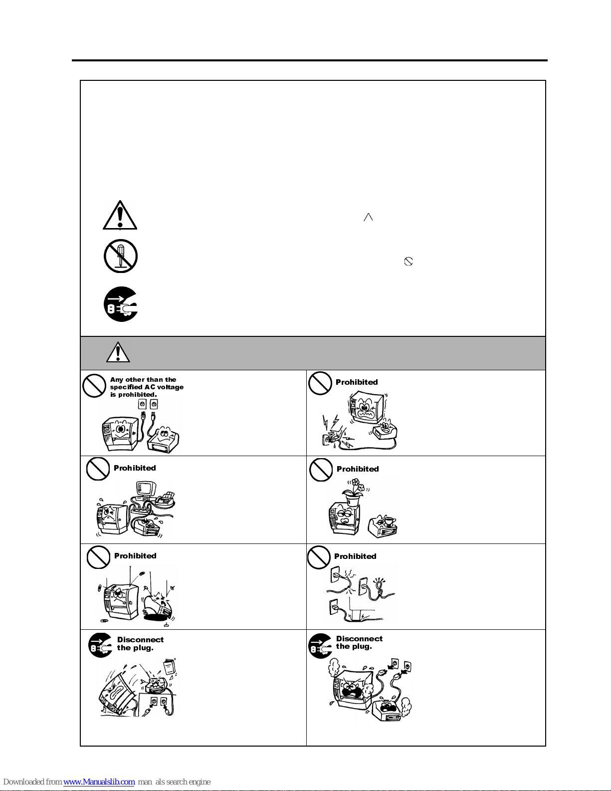
0HDQLQJVRI(DFK6\PERO
This symbol indicates warning items (including cautions).
Specific warning contents are drawn inside the symbol.
(The symbol on the left indicates a general caution.)
This symbol indicates prohibited actions (prohibited items).
Specific prohibited contents are drawn inside or near the
symbol.
(The symbol on the left indicates “no disassembling”.)
This symbol indicates actions which must be performed.
Specific instructions are drawn inside or near the ● symbol.
(The symbol on the left indicates “disconnect the power cord plug from the outlet”.)
This indicates that there is the risk of death or serious injury if the
machines are improperly handled contrary to this indication.
Do not use voltages other than
the voltage (AC) specified on the
rating plate, as this may cause
fire
or
electric shock
.
Do not plug in or unplug the power
cord plug with wet hands as this
may cause
electric shock
.
If the machines share the same
outlet with any other electrical
appliances which consume large
amounts of power, the voltage
will fluctuate widely each time
these appliances operate. Be sure
to provide an exclusive outlet for
the machine as this may cause
fire
or
electric shock
.
Do not place metal objects or
water-filled containers such as
flower vases, flower pots or mugs,
etc. on top of the machin es. If
metal objects or spilled liquid enter
the machines, this may cause
fire
or
electric shock
.
Do not insert or drop metal,
flammable or other foreign
objects into the machines through
the ventilation slits, as this may
cause
fire
or
electric shock
.
Do not scratch, damage or modify
the power cords. Also, do not
place heavy objects on, pull on, or
excessively bend the cords, as this
may cause
fire
or
electrical shock.
If the machines are dropped or
their cabinets damaged, first turn
off the power switches and
disconnect the power cord plugs
from the outlet, and then contact
your authorised TOSHIBA TEC
representative for assistance.
Continued use of the machine in
that condition may cause
fire
or
electric shock
.
Continued use of the machines in
an abnormal condition such as
when the machines are producing
smoke or strange smells may cause
fire
or
electric shock
. In these
cases, immediately turn off the
power switches and disconnect the
power cord plugs from the outlet.
Then, contact your authorised
TOSHIBA TEC representative for
assistance.
:$51,1*
$Q\ RWKHU WKDQ WKH
VSHFLILHG $& YROWDJH
LV SURKLELWHG
3URKLELWHG
3URKLELWHG
3URKLELWHG
3URKLELWHG
3URKLELWHG
'LVFRQQHFW
WKH SOXJ
'LVFRQQHFW
WKH SOXJ
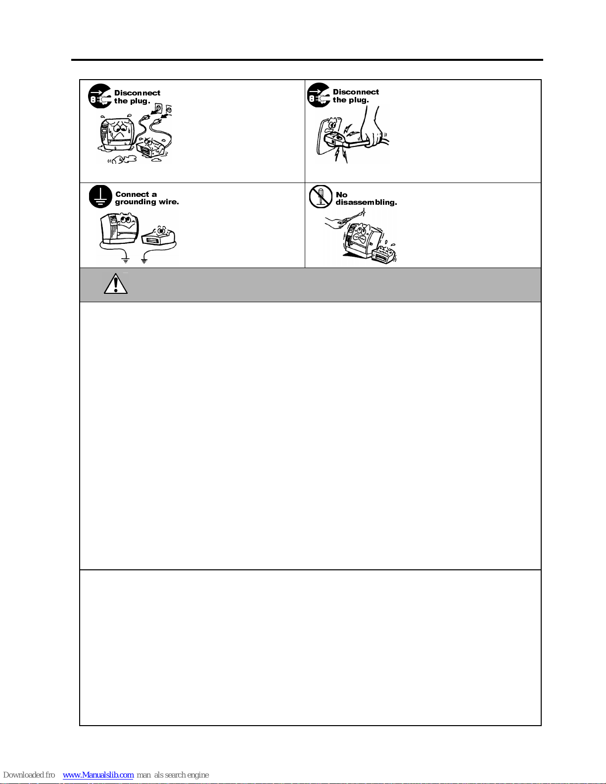
Safety Summary
EO1-33032
( ) ii
If foreign objects (metal
fragments, water, liquids) enter
the machines, first turn off the
power switches and disconnect
the power cord plugs from the
outlet, and then contact your
authorised TOSHIBA TEC
representative for assistance.
Continued use of the machine in
that condition may cause
fire
or
electric shock
.
When unplugging the power cords,
be sure to hold and pull on the plug
portion. Pulling on the cord portion
may cut or expose the internal wires
and cause
fire
or
electric shock
.
Ensure that the equipment is
properly grounded. Extension
cables should also be grounded.
Fire
or
electric shock
could
occur on improperly grounded
equipment.
Do not remove covers, repair or
modify the machine by yourself.
You may be
injured
by high
voltage, very hot parts or sharp
edges inside the machine.
This indicates that there is the risk of personal
Injury
or
damage
to
objects if the machines are improperly handled contrary to this indication.
Precautions
The following precautions will help to ensure that this machine will continue to function correctly.
●
Try to avoid locations that have the following adverse conditions:
* Temperatures out of the specification * Direct sunlight * High humidity
* Shared power source * Excessive vibration * Dust/Gas
●
The cover should be cleaned by wiping with a dry cloth or a cloth slightly dampened with a mild
detergent solution. NEVER USE THINNER OR ANY OTHER VOLATILE SOLVENT on the plastic
covers.
●
USE ONLY TOSHIBA TEC SPECIFIED paper and ribbons.
●
DO NOT STORE the paper or ribbons where they might be exposed to direct sunlight, high
temperatures, high humidity, dust, or gas.
●
Ensure the printer is operated on a level surface.
●
Any data stored in the memory of the printer could be lost during a printer fault.
●
Try to avoid using this equipment on the same power supply as high voltage equipment or equipment
likely to cause mains interference.
●
Unplug the machine whenever you are working inside it or cleaning it.
●
Keep your work environment static free.
●
Do not place heavy objects on top of the machines, as these items may become unbalanced and fall
causing injury.
●
Do not block the ventilation slits of the machines, as this will cause heat to build up inside the
machines and may cause fire.
●
Do not lean against the machine. It may fall on you and could cause injury.
●
Care must be taken not to injure yourself with the printer paper cutter.
●
Unplug the machine when it is not used for a long period of time.
Request Regarding Maintenance
●
Utilize our maintenance services.
After purchasing the machine, contact your authorised TOSHIBA TEC representative for assistance
once a year to have the inside of the machine cleaned. Otherwise, dust will build up inside the
machines and may cause a fire or a malfunction. Cleaning is particularly effective before humid rainy
seasons.
●
Our preventive maintenance service performs the periodic checks and other work required to maintain
the quality and performance of the machines, preventing accidents beforehand.
For details, please consult your authorised TOSHIBA TEC representative for assistance.
●
Using insecticides and other chemicals
Do not expose the machines to insecticides or other volatile solvents. This will cause the cabinet or
other parts to deteriorate or cause the paint to peel.
&$87,21
'LVFRQQHFW
WKH SOXJ
&RQQHFW D
JURXQGLQJ ZLUH
'LVFRQQHFW
WKH SOXJ
1R
GLVDVVHPEOLQJ

EO1-33032
TABLE OF CONTENTS
Page
1. PRODUCT OVERVIEW...........................................................................................................1-1
1.1 Introduction.....................................................................................................................1-1
1.2 Features.........................................................................................................................1-1
1.3 Unpacking ...................................................................................................................... 1-1
1.4 Accessories ...................................................................................................................1-1
1.5 Appearance of the Printer...............................................................................................1-2
1.5.1 Dimensions..................................................................................................................... 1-2
1.5.2 Front View...................................................................................................................... 1-3
1.5.3 Side View ....................................................................................................................... 1-3
1.5.4 Interior ............................................................................................................................ 1-4
1.5.5 Operation Panel............................................................................................................. 1-4
1.6 Appearance of the Power Supply Unit ............................................................................1-5
1.6.1 Dimensions..................................................................................................................... 1-5
1.6.2 Front View...................................................................................................................... 1-5
2. PRINTER SETUP....................................................................................................................2-1
2.1 Precautions ....................................................................................................................2-1
2.2 Procedure before Operation ...........................................................................................2-2
2.3 Fitting the Fan Filter........................................................................................................ 2-2
2.4 Connecting the Cables to Your Printer............................................................................2-3
2.5 Connecting the Power Cord............................................................................................2-4
2.6 Turning the Printer ON/OFF............................................................................................2-5
2.6.1 Turning ON the Printer................................................................................................... 2-5
2.6.2 Turning OFF the Printer................................................................................................. 2-5
2.7 Loading the Media..........................................................................................................2-6
2.8 Loading the Ribbon ......................................................................................................2-11
2.9 Inserting the Optional PCMCIA Cards ..........................................................................2-12
2.10 Test Print......................................................................................................................2-13
3. ON LINE MODE ......................................................................................................................3-1
3.1 Operation Panel..............................................................................................................3-1
3.2 Operation........................................................................................................................3-2
4. MAINTENANCE......................................................................................................................4-1
4.1 Cleaning.........................................................................................................................4-1
4.1.1 Print Head/Platen........................................................................................................... 4-1
4.1.2 Media Guide Plate/Pinch Roller/Sensors....................................................................... 4-2
4.1.3 Paper Holder.................................................................................................................. 4-4
4.1.4 Covers and Panels......................................................................................................... 4-4
4.2 Care/Handling of the Media and Ribbon.........................................................................4-5
5. TROUBLESHOOTING ............................................................................................................5-1
5.1 Error Messages..............................................................................................................5-1
5.2 Possible Problems..........................................................................................................5-2
5.3 Removing Jammed Media..............................................................................................5-3
5.4 Threshold Setting ...........................................................................................................5-3
6. PRINTER OPERATION...........................................................................................................6-1
6.1 Overview ........................................................................................................................6-1
6.2 Installing the Printer Drivers............................................................................................6-1
6.2.1 System Requirements.................................................................................................... 6-2
6.2.2 Driver Installation............................................................................................................ 6-2
6.2.3 Uninstalling the TEC B-492 Printer Driver..................................................................... 6-6

EO1-33032
APPENDIX 1 SPECIFICATIONS ................................................................................................ A1-1
A1.1 Printer.......................................................................................................................... A1-1
A1.2 Options........................................................................................................................ A1-2
A1.3 Media .......................................................................................................................... A1-2
A1.3.1 Media Type.................................................................................................................A1-2
A1.3.2 Detection Area of the Transmissive Sensor...............................................................A1-3
A1.3.3 Detection Area of the Reflective Sensor ....................................................................A1-4
A1.3.4 Effective Print Area.....................................................................................................A1-4
A1.4 Ribbon......................................................................................................................... A1-5
APPENDIX 2 MESSAGES AND LED ......................................................................................... A2-1
APPENDIX 3 INTERFACE.......................................................................................................... A3-1
APPENDIX 4 SYSTEM MODE.................................................................................................... A4-1
A4.1 Operation Panel........................................................................................................... A4-1
A4.2 Overview ..................................................................................................................... A4-2
A4.3 Reset Mode................................................................................................................. A4-3
A4.4 Self-Diagnostic Test .................................................................................................... A4-3
A4.5 Printer Parameter Fine Adjustment.............................................................................. A4-6
A4.6 Test Print................................................................................................................... A4-14
A4.7 Dump Mode............................................................................................................... A4-20
A4.8 Additional Information................................................................................................ A4-21
A4.8.1 Self-Diagnostic Test Result Sample and Descriptions.............................................A4-21
A4.8.2 Maintenance Counter/Parameter Check Print Sample and Descriptions................A4-24
A4.8.3 Magnified Views of Slant Line Pattern......................................................................A4-27
APPENDIX 5 PRINT SAMPLES ................................................................................................. A5-1
GLOSSARIES
INDEX
CAUTION!
1. This manual may not be copied in whole or in part without prior written permission of TOSHIBA TEC.
2. The contents of this manual may be changed without notification.
3. Please refer to your local Authorized Service representative with regard to any queries you may have in
this manual.
1. PRODUCT OVERVIEW
EO1-33032
1.1 Introduction
1- 1
1. PRODUCT OVERVIEW
1.1 Introduction
1.2 Features
1.3 Unpacking
1.4 Accessories
Thank you for choosing the TEC B-492L/R series barcode printer. This
Owner’s Manual contains valuable information from general set-up to
confirming the printer's operation using test prints. You should read it
carefully to help you gain maximum performance and life from your
printer. This manual should be kept close at hand for everyday reference.
Please contact your TOSHIBA TEC representative for further
information concerning this manual.
The B-492L/R printer has the following features:
•
Superior hardware, including a specially developed 12 dots/mm (300
dots/inch) thermal print head which gives very clear print quality at
print speeds of 127 mm/sec. (5 inches/sec.), 203.2 mm/sec. (8
inches/sec.), and 254 mm/sec. (10 inches/sec.).
•
Separation of the power supply unit realized a compact body of the
printer.
•
When the optional interface board is installed, Web functions such as
remote maintenance and other advanced network functions are
available.
•
The PCMCIA Interface Board and the KB-80-QM Keyboard Unit are
provided as optional equipment.
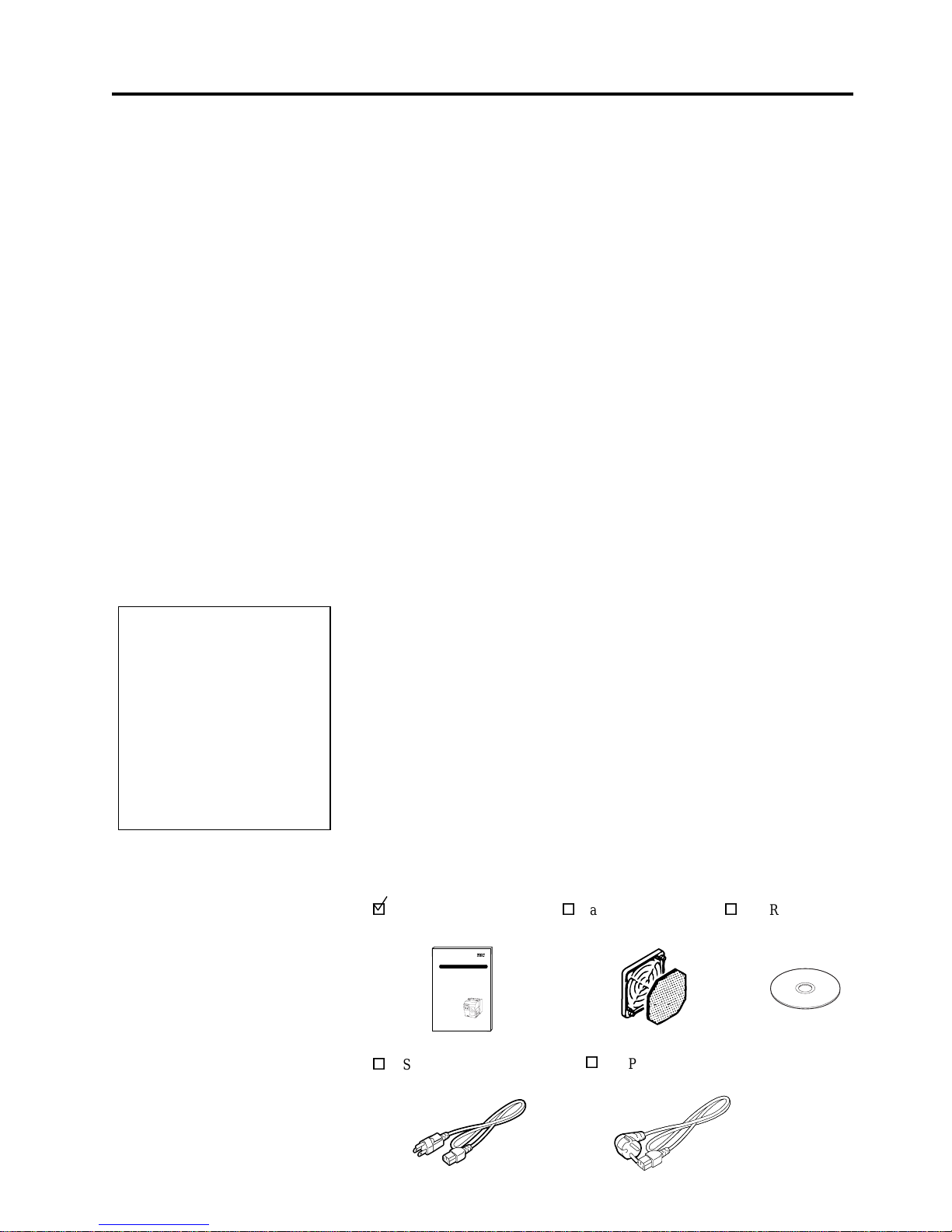
Unpack the printer as per the Unpacking Instructions supplied with the
printer.
When unpacking the printer, please check that the following accessories
are supplied with the printer.
Owner’s Manual (1 copy)
(Doc./No. EO1-33032)
US Power Cord (1 pc.)
(P/No. FBCB0030202)
NOTES:
1. Check for damage or
scratches on the printer.
However, please note that
TOSHIBA TEC shall have no
liability for any damage of
any kind sustained during
transportation of the
product.
2. Keep the cartons and pads
for future transportation of
the printer.
Fan Filter
(P/No. FMBB0036801)
TOSHIBA TEC CORPORATION
TEC Label/Tag Printer
B-492-QQ
Owner?s Manual
EU Power Cord (1 pc.)
(
P/No.: EKA-0055001)
CD-ROM
(P/No. FMQB0083801)
1. PRODUCT OVERVIEW
EO1-33032
1.5 Appearance of the Printer
1- 2
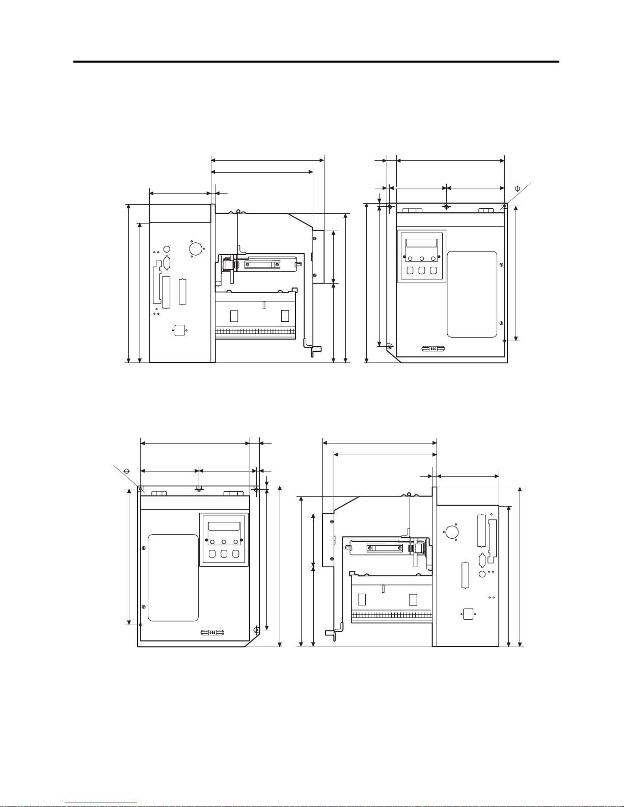
1.5 Appearance of the Printer
1.5.1 Dimensions
[L Type]
[R Type]
5x 5.5
256 (10.1)
265 (10.4)
300 (11.8)
5 (0.2)
18 (0.7)
223 (8.8)
5 (0.2)
117.5 (4.6)
117.5 (4.6)
232.5 (9.2)
209.3 (8.2)
10 (0.4)
125 (4.9)
100 (3.9)
282 (11.1)
149.3 (5.9)
264 (10.4)
300 (11.8)
5x 5.5
117.5 (4.6)
117.5 (4.6)
223 (8.8) 18 (0.7)
5 (0.2)
256 (10.1)
265 (10.4)
5 (0.2)
300 (11.8)
100 (3.9)
149.3 (5.9)
264 (10.4)
300 (11.8)
282 (11.1)
232.5 (9.2)
209.3 (8.2)
10 (0.4)
125 (4.9)
Dimension: mm+(inch)
1. PRODUCT OVERVIEW
EO1-33032
1.5 Appearance of the Printer
1- 3
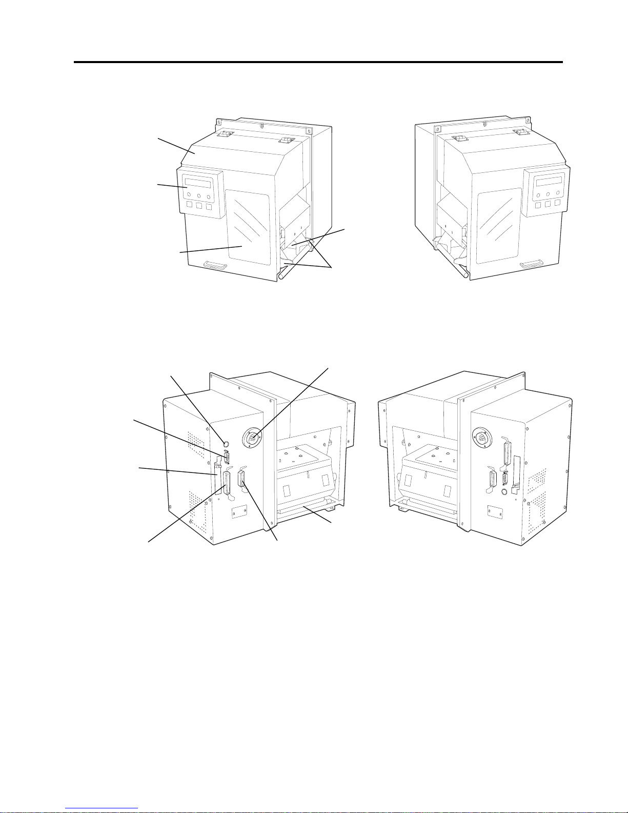
1.5.2 Front View
[L Type] [R Type]
1.5.3 Side View
[L Type] [R Type]
Top Cover
Operation Panel
Media Inlet
Media Guide
Supply Window
Print Head
DC Power Connector
PCMCIA Card
Slot (2 slots)
Keyboard Interface
Connector
Expansion I/O
Interface Connector
Parallel Interface
Connector
(Centronics)
Serial Interface
Connector
(RS-232C)
1. PRODUCT OVERVIEW
EO1-33032
1.5 Appearance of the Printer
1- 4
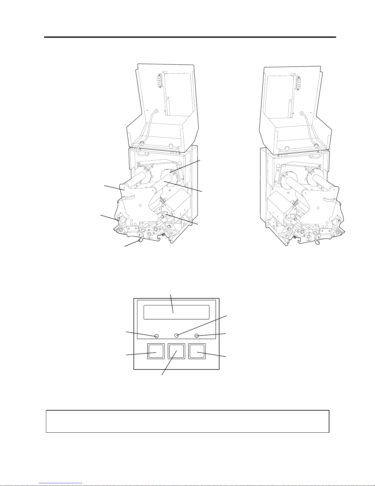
1.5.4 Interior
[L Type] [R Type]
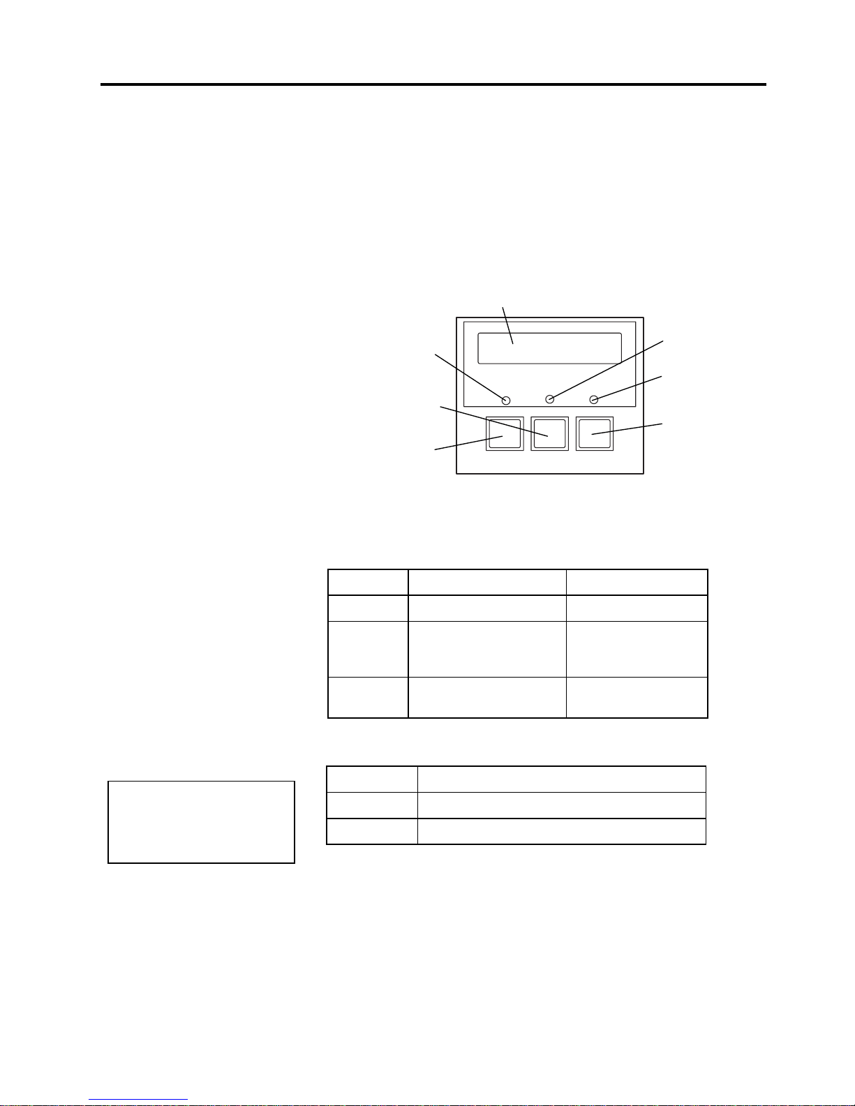
1.5.5 Operation Panel
Please see Section 3.1 for further information about the Operation Panel.
Ribbon Stopper
Ribbon Shaft
Ribbon Shaft
Holder Plate
Pinch Roller Lever
Head Lever
Strip Roller Release Lever
FEED RESTART PAUSE
POWER ON LINE ERROR
LCD Message Display
[
FEED
]
Key
ERROR LED (Red)
ON LINE LED (Green)
POWER LED (Green)
[RESTART]
key
[PAUSE]
key
N
OTE:
The illustrations used hereafter are of the L type, as the operating procedure is common to both L and R types.
1. PRODUCT OVERVIEW
EO1-33032
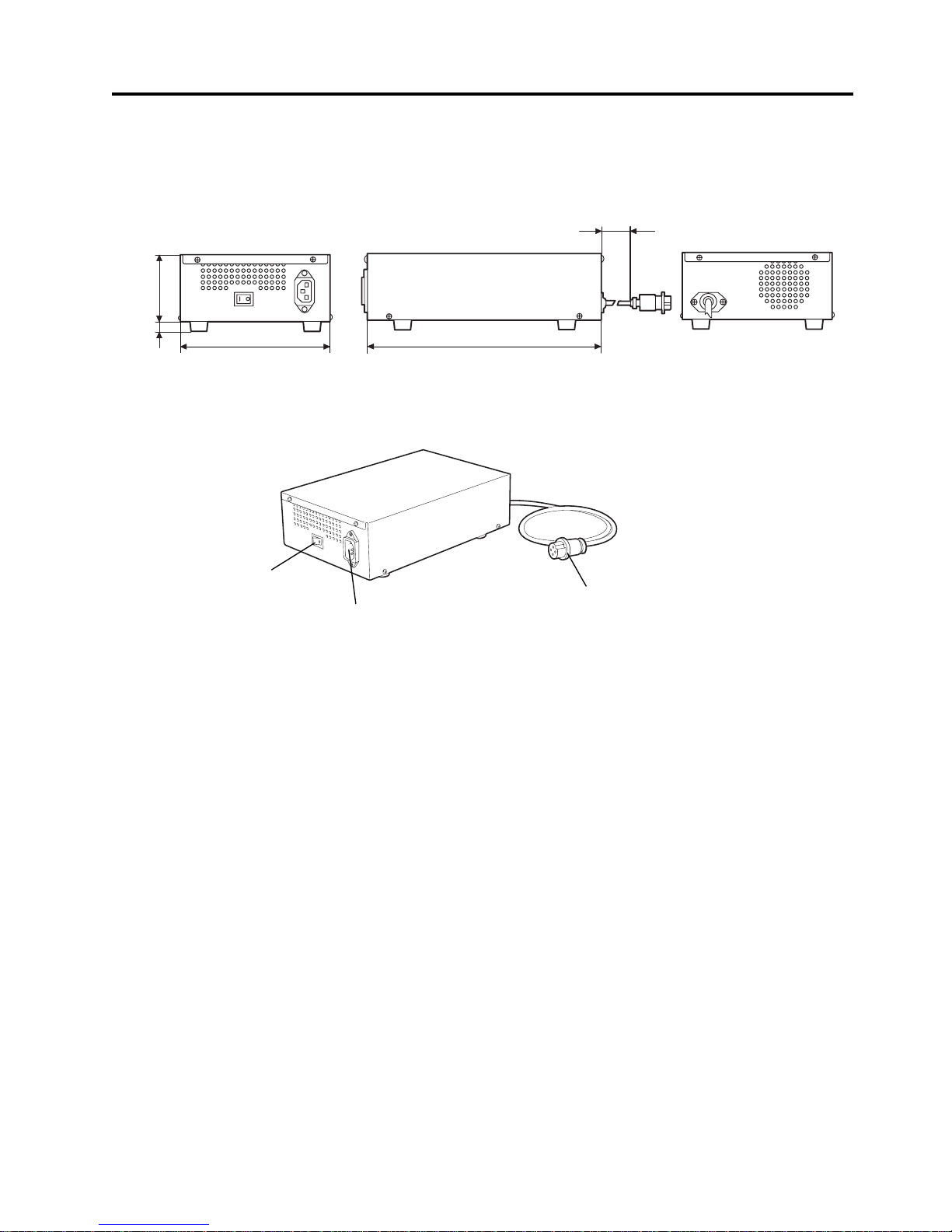
1.6 Appearance of the Power Supply Unit
1- 5
1.6 Appearance of the Power Supply Unit
1.6.1 Dimensions
Dimensions: mm+(inch)
1.6.2 Front View
2000 (78.7)
265 (10.4)
10 (0.4)
76 (3.0)
170 (6.7)
DC Power Connector
Power Switch
Inlet

2. PRINTER SETUP
EO1-33032
2.1 Precautions
2- 1
2. PRINTER SETUP
2.1 Precautions
This section outlines the steps necessary to setup your B-492L/R printer
prior to its operation. The section includes precautions, connecting
cables, assembling accessories, loading media and ribbon, inserting an
optional memory card, and performing a test print.
• To insure the best operating environment, and to assure the safety of
the operator and the equipment, please observe the following
precautions.
• Operate the printer on a stable, level, operating surface in a location
free from excessive humidity, high temperature, dust, vibration or
direct sunlight.
• Keep your work environment static free. Static discharges can cause
damage to delicate internal components.
• Make sure that the printer is connected to a clean source of AC Power
and that no other high voltage devices that may cause line noise
interference are connected to the same mains.
• Ensure that the printer is connected only to AC mains that has a
proper ground (earth) connection.
• Only use the power cable provided with this unit to power it..
• Do not operate the printer with the cover open. Be careful not to
allow fingers or articles of clothing to get caught into any of the
moving parts of the printer.
• Make sure to turn off the printer power and to remove the power cord
from the printer whenever working on the inside of the printer or
when cleaning the printer.
• For best results, and longer printer life, use only TOSHIBA TEC
recommended media and ribbons.
• Store the media and ribbons in accordance with their specifications.
• This printer mechanism contains high voltage components; therefore
you should never remove any of the covers of the machine as you may
receive an electrical shock. Additionally, the printer contains many
delicate components that may be damaged if accessed by unauthorized
personnel.
• Clean the outside of the printer with a clean dry cloth or a clean cloth
slightly dampened with a mild detergent solution.
• Use caution when cleaning the thermal print head as it may become
very hot while printing. Wait until it has had time to cool before
cleaning. Use only the TOSHIBA TEC recommended print head
cleaner to clean the print head.
• Do not turn off the printer power or remove the power plug while the
printer is printing or while the ON LINE lamp is blinking.
2. PRINTER SETUP
EO1-33032
2.2 Procedure before Operation
2- 2
2.2 Procedure before
Operation
2.3 Fitting the Fan Filter
This section describes the outline of the printer setup.
1.
Unpack the accessories and printer from the box.
2.
Refer to Safety Precautions in this manual and set up the printer at a
proper location.
3.
Attach the fan filter to the rear of the printer. (Refer to Section 2.3.)
4.
The host computer must have an available serial port, Centronics
parallel port or a Ethernet (option) connection. (Refer to Section
2.4.)
5.
Connect the DC power cord plug to the printer. Connect the AC
power cord to the Power Supply Unit. (Refer to Section 2.5.)
6.
Load the media in the printer. (Refer to Section 2.7.)
7.
Adjust the position of the Feed Gap Sensor or Black Mark Sensor to
match the media being used. (Refer to Section 2.7.)
8.
Load the ribbon onto the Ribbon Shafts. (Refer to Section 2.8.)
9.
Turn the Power ON. (Refer to Section 2.6.)
10.
Set the threshold. (Refer to Section 5.4.)
11.
Perform a test print. (Refer to Section 2.10 and Appendix 4.6.)
12.
Install the Printer Drivers. (Refer to Section 6.)
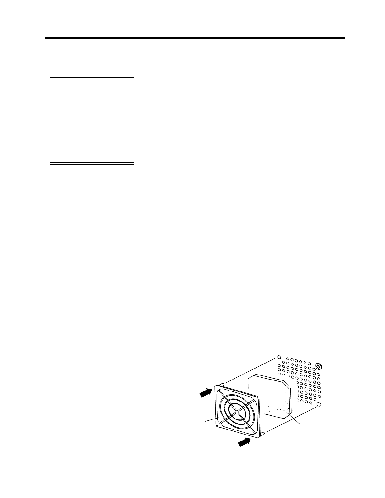
When installing the printer, it is important to ensure that the fan filter is
attached before using the printer.
The fan filter consists of 2 parts:
(1) Filter Pad
(2) Filter Retainer
To fit the fan filter, put the filter pad inside the filter retainer and simply
press into place as shown in the diagram below, ensuring connecting pins
are aligned with the connecting holes.
NOTE:
Use of a Windows Driver will
allow issuing media on the B492L/R printer from a
Windows application.
The printer can also be
controlled with its own
p
rogramming commands.
Please contact your TOSHIBA
TEC reseller for the
I
nterface/Communication
M
anual.
NOTE:
To communicate directly
with a host computer, either
an RS-232C cable or
Centronics cable is required.
(1) RS-232C cable: 9 pins
(do not use a null modem
cable)
(2) Centronics cable: 36 pins
(3) Expansion I/O cable: 24
pins (Option)
Snap on
Snap on
(2)
(1)
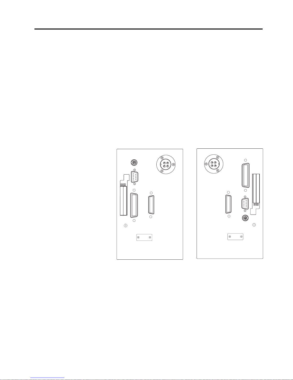
2. PRINTER SETUP
EO1-33032
2.4 Connecting the Cables to Your P ri nter
2- 3
2.4 Connecting the
Cables to Your
Printer
The following paragraphs outlines how to connect the cables from the B492L/R printer to your host computer, and will also show how to make
cable connections to other devices such as the KB-80-QM keyboard, etc.
Depending on the application software you use to print labels, there are
two possibilities for connecting the printer to your host computer. These
are:
• A serial cable connection between the printer’s RS-232 serial
connector and one of your host computer’s COM ports
(Refer to APPENDIX 3.)
• A parallel cable connection between the printer’s standard parallel
connector and your host computer’s parallel port (LPT).
• An Ethernet connection using the optional PCMCIA interface
board and LAN card (Refer to section 2.9)
The diagram below shows all the possible cable connections to the
current version of the B-492L/R printer.
[L Type] [R Type]
c
Parallel Interface Connector (Centronics)
d
Serial Interface Connector (RS-232C)
e
KB-80-QM Keyboard Interface Connector (Option)
f
Expansion I/O Interface Connector
c
d
e
f
c
d
e
f
2. PRINTER SETUP
EO1-33032
2.5 Connecting the Power Cord
2- 4
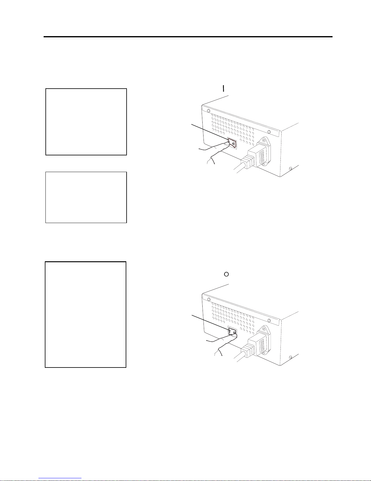
2.5 Connecting the
Power Cord
1
. Connect the DC power cable from the DC Power Supply Unit to the
printer.
2.
Make sure that the printer power switch is in the OFF (O) position.
3.
Connect the power cord to the Power Supply Unit as shown in the
figure below.
4.
Plug the other end of the power cord into a grounded outlet as shown
in the figure below.
CAUTION!
1. Make sure that the
printer power switch is
turned to the off
position before
connecting the power
cord to prevent
possible electric shock
or damage to the
printer.
2. Use only the power
cord supplied with the
printer. Use of any
other cord may cause
electric shock or fire.
3. Connect the power
cord to a supply outlet
with a properly
grounded (earthed)
connection.
Power Cord
DC Power Cable
Power Switch
Power Cord
[QQ Type] [QP Type]
2. PRINTER SETUP
EO1-33032
2.6 Turning the Printer ON/OFF
2- 5
2.6 Turning the Printer
ON/OFF
2.6.1 Turning ON the Printer
2.6.2 Turning OFF the
Printer
When the printer is connected to a host computer it is good practice to
turn the printer ON before turning on the host computer and to turn OFF
the host computer before turning off the printer.
1.
To turn ON the printer power, press the power switch as shown in the
diagram below. Note that ( ) is the power ON side of the switch.
2.
Check that the message ON LINE appears on the LCD Display and
that the ON LINE and POWER LED lights are illuminated
1.
Before turning off the printer power switch verify that the ON LINE
message is on the LCD Message Display and that the ON LINE LED
light is on and not flashing.
2.
To turn OFF the printer power press the power switch as shown in the
diagram below. Note that ( { ) is the power OFF side of the switch.
CAUTION!
Use the power switch to
turn the printer On/Off.
Plugging or unplugging the
power cord to turn the
printer On/Off may cause
fire, an electric shock, or
damage to the printer.
CAUTION!
1. Do not turn off the
printer power while the
media is being printed
as this may cause a
paper jam or damage
to the printer.
2. Do not turn off the
printer power while the
ON LINE light is
blinking as this may
cause damage to your
host computer.
NOTE:
I
f a message other than ON
L
INE appears on the display o
r
the ERROR LED lamp is
illuminated, go to Chapter 5.1,
Error Messages.
Power Switch
Power Switch

2. PRINTER SETUP
EO1-33032
2.7 Loading the Media
2- 6
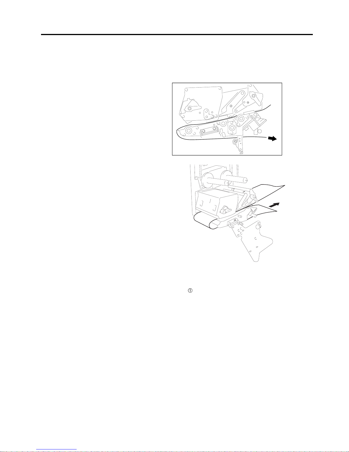
2.7 Loading the Medi a
This section describes in detail how to load the media.
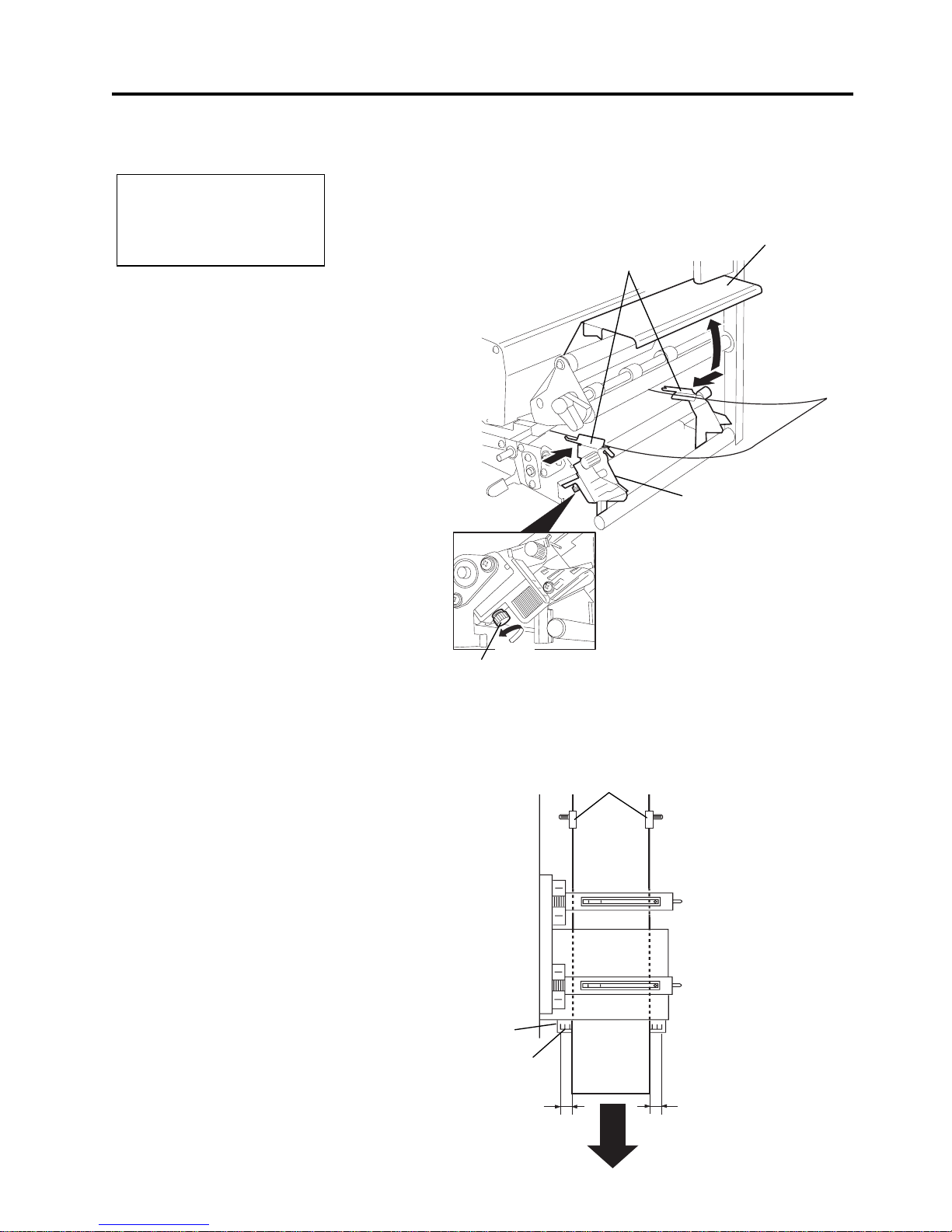
1.
Open the top cover and turn the head lever and pinch roller lever to
position d, then open the ribbon shaft holder plate.
2.
Insert the media into the printer from the side as shown in the figure
below. Ensure that the media is positioned in the black mark/feed gap
sensor.
WARNING!
1. Do not touch any moving
parts. To reduce the ris
k
of fingers, jewellery,
clothing, etc. being
drawn into the moving
parts, be sure to load the
media once the printer
has stopped moving
completely.
2. To avoid injury, be
careful not to trap your
fingers while opening or
closing the cover.
3. Be sure to open the top
cover fully, otherwise the
top cover may close,
causing injury.
NOTES:
1. When the head lever is
turned to position d, the
print head is raised.
2. When the pinch roller lever
is turned to position d, the
pinch roller is raised.
3. To enable printing the head
lever and the pinch roller
lever must be set to position
c
. This ensures that the
print head and the pinch
roller are closed.
HEAD
2
1
c
d
Top Cover
Head Lever
Ribbon Shaft
Holder Plate
Pinch Roller
Lever
Media
2. PRINTER SETUP
EO1-33032
2.7 Loading the Media
2- 7
2.7 Loading the Media
(Cont.)
3.
Open the paper entry guide.
4.
Loosen the locking screw of the right side of the media guide and
open the media guides.
5.
Insert each edge of the media into the paper holders of the media
guides by adjusting the media guides positions to the media width.
Then tighten the locking screw.
6.
Pass the media straight from the paper holders to paper outlet. The
media should be centred on the strip plate, otherwise skew feeding or
a paper jam may occur. Check that the media is positioned so that the
distances from the media edge to the end of the scale marked on the
strip plate (Distances A and B in the figure below.) are almost equal.
NOTE:
The media guide should be
p
ositioned so that the media
can feed smoothly.
Paper Entry Guide
Locking Screw
Paper Holder
Media Guide
Loose
A
B
Strip Plate
Media
Paper Holder
Distances A and B should
be almost equal.
Scale
2. PRINTER SETUP
EO1-33032
2.7 Loading the Media
2- 8
2.7 Loading the Media
(Cont.)
7.
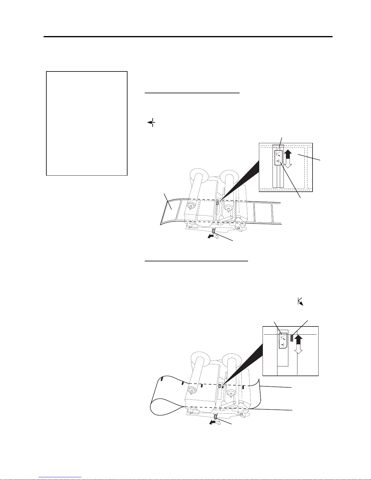
After loading the media, it may be necessary to set the media sensors
used to detect the print start position of the labels. Set the black
mark/feed gap sensor to the correct position by turning the adjusting
knob.
Setting the feed gap sensor position
Turn the adjusting knob to move the feed gap sensor to the centre of the
labels to detect the gap between labels. If the labels are round, set the
sensor to detect the area of the shortest distance between the labels.
( indicates the position of the feed gap sensor).
Setting the black mark sensor position
(1) Pull about 500 mm of media out of the front of the printer, turn the
media back on itself and feed it under the print head past the sensor
so that the black mark can be seen from above.
(2) Turn the adjusting knob to move the black mark sensor so that it is
in line with the center of the black mark on the media. ( indicates
the position of the black mark sensor.)
NOTES:
1. Turning the adjusting knob
to the right will move the
sensor towards the center
of the media while turning
it to the left will move it
away from the center of the
media.
2. Be sure to set the black
mark sensor to detect the
center of the black mark,
otherwise a paper jam or
no paper error may occur.
Label
Feed Gap Sensor
Label
Adjusting Knob
Gap between Labels
Black Mark Sensor
Black Mark
Adjusting Knob
2. PRINTER SETUP
EO1-33032
2.7 Loading the Media
2- 9
2.7 Loading the Media
(Cont.)
8.
There are two issue modes available on this printer.
Batch mode:
In the batch mode, the media is continuously printed and fed until the
number of issues specified in the label issue command has been printed.
If the loaded media is direct thermal media (a chemically treated surface),
the media loading procedure is now complete. Close the ribbon shaft
holder plate, and turn the head lever and the pinch roller lever to position
c
to close. Then, close the top cover.
If the media is a standard media, it is also necessary to load a ribbon.
Refer to the section, 2.8 Loading the Ribbon.
Strip mode:
In strip mode, as each label is printed the backing paper is automatically
removed from the label at the strip plate.
(1) Set the ribbon shaft holder plate, and turn the head lever and the
pinch roller lever to position c to close.
(2) Remove enough labels from the leading edge of the media to leave
500 mm of backing paper free.
(3) Push the pinch roller release lever toward the front of the printer to
release the strip pinch roller unit.
Media
Pinch Roller
Release Lever
Backing Paper
Strip Pinch Roller Unit
CAUTION!
To separate the printed
media from the media roll
in batch mode, be sure to
tear off the media at the
strip shaft or cut the media
past the strip shaft.
However, if you tear off
the media at the print
head by mistake, be sure
to feed one label (10 mm
or more) with the [FEED]
key prior to next issue.
Failure to do this may
cause a paper jam.
2. PRINTER SETUP
EO1-33032
2.7 Loading the Media
2-10
2.7 Loading the Media
(Cont.)
(4) Pass the backing paper under the strip plate and abov e the strip pinch
roller.
(5) While pulling the backing paper push up the strip pinch roller until it
locks into position.
(6) If the loaded media is direct thermal media (a chemically treated
surface), the media loading procedure is now complete. Close the
ribbon shaft holder plate, and turn the head lever and the pinch roller
lever to position c to close. Then, close the top cover.
If the media is a standard media, it is also necessary to load a ribbon.
Refer to the following section, 2.8 Loading the Ribbon.
2. PRINTER SETUP
EO1-33032
2.8 Loading the Ribbon
2-11
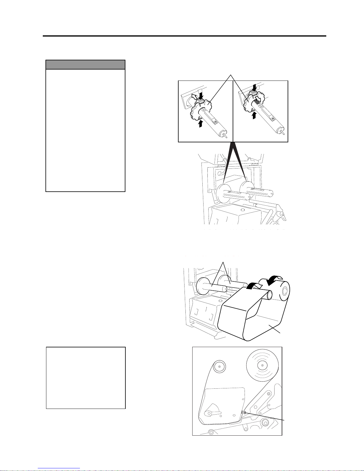
2.8 Loading the Ribbon
1.
Grasp the tabs on the top and bottom of the ribbon stoppers and move
the ribbon stoppers back to the end of the shaft.
2.
Leaving plenty of slack between the ribbon spools, place the ribbon
onto the ribbon shafts as shown below. When the ribbon is fitted, it
must be positioned in the ribbon sensor.
WARNING!
1. Do not touch any moving
parts. To reduce the ris
k
of fingers, jewellery,
clothing, etc. being
drawn into the moving
parts, be sure to load the
ribbon once the printer
has stopped moving
completely.
2. To avoid injury, be
careful not to trap your
fingers while opening or
closing the cover.
3. Be sure to open the top
cover fully, otherwise the
top cover may close,
causing injury.
Ribbon Stopper
Ribbon
Ribbon Shafts
Ribbon Sensor
NOTE:
The ribbon sensor is mounted on
the rear of the printer block to
detect a ribbon end. When a
ribbon end is detected, “NO
R
IBBON” message will appear
on the display and the ERROR
L
ED will illuminate.
2. PRINTER SETUP
EO1-33032
2.9 Inserting the Optional PCMCIA Cards
2-12
2.8 Loading the Ribbon
(Cont.)
2.9 Inserting the Optional
PCMCIA Cards
3.
Slide the ribbon stoppers along the ribbon shafts to a position where
the ribbon is centered when fitted.
4.
Take up any slack in the ribbon. Take the leading tape onto the ribbon
take-up roll until the ink ribbon can be seen from the front.
5.
Set the ribbon shaft holder plate aligning its holes with the ribbon
shafts.
6.
Turn the head lever and the pinch roller lever to position c to close
the print head and the pinch roller.
7.
Close the top cover.
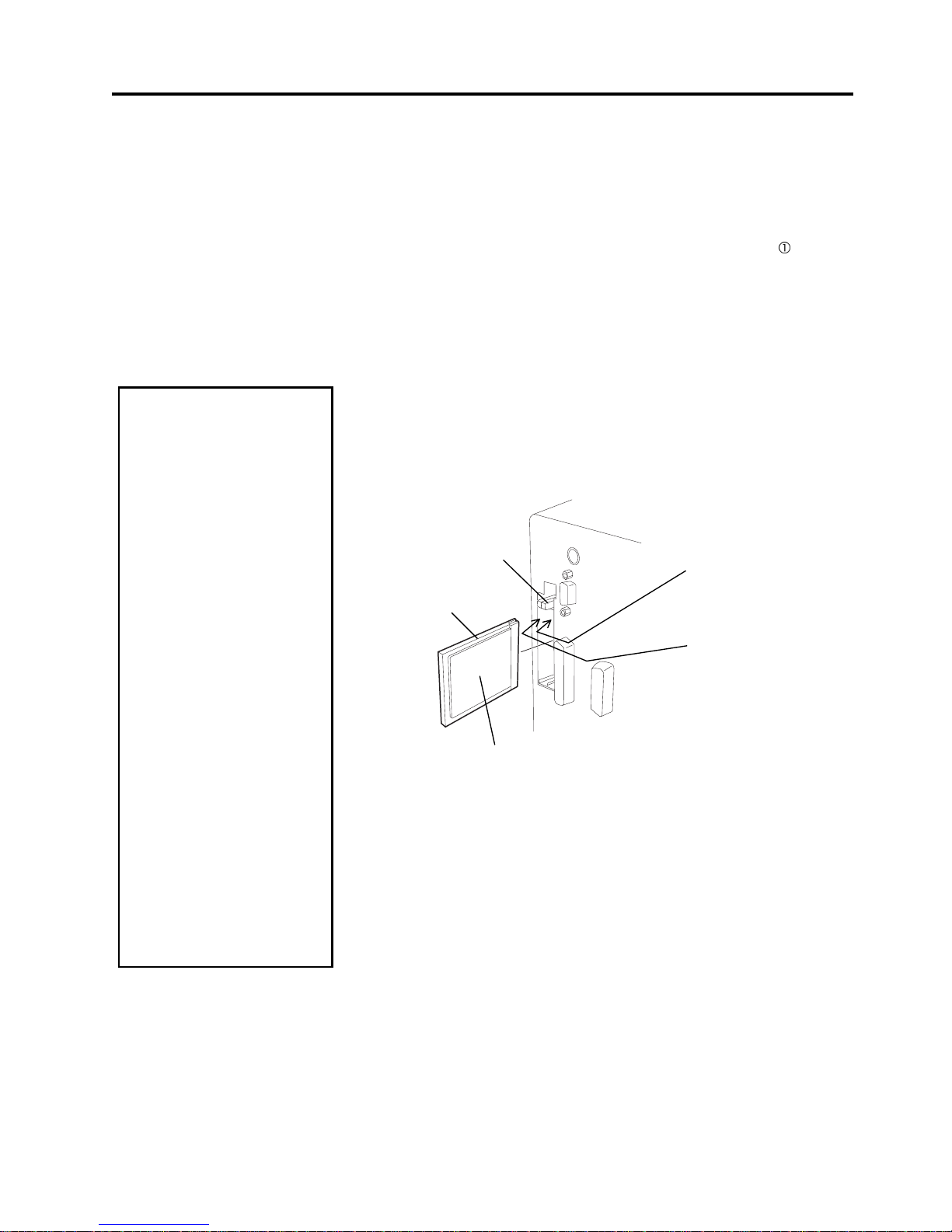
When the optional PCMCIA interface board is installed in the B-492L/R
printer, there will be two PCMCIA slots available as shown in the figure
below. This allows the use of Flash Memory Type Cards or I/O Cards
such as LAN Cards.
1.
Make sure that the printer’s power switch is in the OFF position.
2.
Hold the PCMCIA Card so that the side printed with the model name
faces right. Insert the card into the proper slot until the Eject Button
pops out.
CAUTION!
1. To protect PC cards,
discharge static
electricity from your body
by touching the metal
cabinet of the printer
before touching the card.
2. Before inserting or
removing a PCMCIA
card make sure that the
printer’s power is turned
off.
3. Be sure to protect
PCMCIA Cards when not
in use by putting them
into their protective
covers.
4. Do not subject the card
to any shocks or
excessive force nor
expose the card to
extremes in temperature
or humidity
5. The card may be
inserted into the slot
halfway even in the
wrong orientation.
However, the slot is
safety designed so that
the card will not seat
against the connector
pins.
Slot 1:
(I/O type cards such as
LAN cards
)
Slot 0:
(Memory type cards only)
Eject Button
Model Name Printed Side
Flash Memory
Type Card
2. PRINTER SETUP
EO1-33032
2.10 Test Print
2-13
2.9 Inserting the
Optional PCMCIA
Cards (Cont.)
2.10 Test Print
3.
The following PCMCIA cards can be used.
Type Maker Description Remarks
ATA Card
San Disk
Hitachi
A card conforming to
the PC card ATA
standard
----------
Ether Link III 3C589D
PC card
LAN Card 3 COM
Megahertz®
10M bps LAN PC Card
3CCE589ET Series
Install into the slot (1)
only. (This card
installed into the slot
(0) will not work.)
Maxell
EF-1M-TB AA
Mitsubishi MF-81M1-GBDAT01
Capacity: 1MB
Read only
EF-4M-TB CC
Maxell
EF-4M-TB DC
Capacity: 4MB
Readable/writable
Centennial
Technologies
INC.
FL04M-15-11119-03
INTEL IMC004FLSA
Simple
TECHNOLOGY
STI-FL/4A
Mitsubishi MF84M1-G7DAT01
PC Card KING
MAX
FJN-004M6R
Flash Memory
Card
PC Card FJP-004M6R
Capacity: 4MB
Read only
A print test should be performed to check that the printer is operating
correctly. During this test, the printer will first issue a blank page of
media to allow the sensors to detect the Black Mark or Label Gap. Then it
will print five pages of slanted lines followed by five pages of sample bar
codes then finally by printing five pag es that contain characters of v arious
sizes.
For the test print procedure, please refer to Appendix 4.6 Test Print.
3. ON LINE MODE
EO1-33032
3.1 Operation Panel
3- 1
3. ON LINE MODE
3.1 Operation Panel
This chapter describes usage of the keys on the Operation Panel in On
Line Mode.
When the printer is in On Line Mode and connected to a host computer,
the normal operation of printing images on labels can be achieved.
The figure below shows the Operation Panel and key functions..
The LCD Message Display shows messages to indicate the printer’s
current status. Up to 16 characters can be displayed on this line.
There are three LED lights on the Operation Panel.
LED Illuminates when… Flashes when…
POWER
The printer is turned on. -----
ON LINE
The printer is ready to
print.
The printer is
communicating with
your computer.
ERROR
Any error occurs on the
printer.
-----
There are three keys on the Operation Panel.
PAUSE
Used to stop printing temporarily.
RESTART
Used to restart printing.
FEED
Used to feed the media.
FEED RESTART PAUSE
POWER ON LINE ERROR
NOTE:
Use the
[RESTART]
key to
resume printing after a pause,
or after clearing an error.
LCD Message Display
ON LINE LED (Green)
ERROR LED (Red)
[PAUSE] key
POWER LED
(
Green)
[FEED] ke
y
[RESTART] ke
y
3. ON LINE MODE
EO1-33032
3.2 Operation
3- 2
3.2 Operation
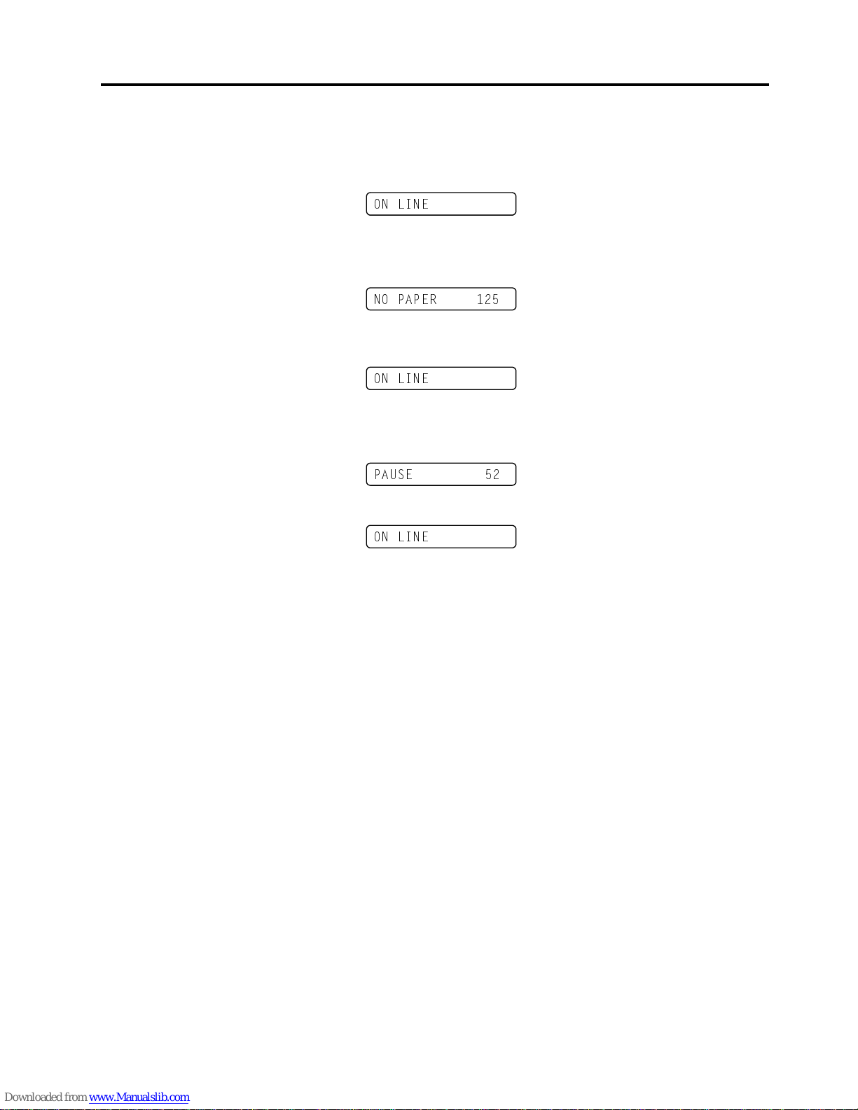
When the printer is turned on, the “ON LINE” message appears on the
LCD message display. It is displayed during standby or normal printing.
1.
The printer is turned on, standing by, or printing.
2.
If any error occurs during printing, an error message appears. The
printer stops printing automatically. (The number on the right hand
side shows the remaining number of labels to be printed.)
3.
To clear the error, press the
[RESTART]
key. The printer resumes
printing.
4
. If the
[PAUSE]
key is pressed during printing, the printer stops
printing temporarily. (The number on the right hand side shows the
remaining number of labels to be printed.)
5.
When the
[RESTART]
key is pressed, the printer resumes printing.
21 /,1(
12 3$3(5
21 /,1(
3$86(
21 /,1(

4. MAINTENANCE
EO1-33032
4.1 Cleaning
4- 1
4. MAINTENANCE
4.1 Cleaning
4.1.1 Print Head/Platen
This chapter describes how to perform routine maintenance.
To ensure the continuous high quality operation of your B-492L/R, you
should perform a regular maintenance routine. For high throughput it
should be done on a daily basis. For low throughput it should be done on
a weekly basis.
To maintain the printer performance and print quality, please clean the
printer regularly, or whenever the media or ribbon is replaced.
1.
Turn the power off.
2.
Open the top cover.
3.
Turn the head lever and pinch roller lever to position d, then open the
ribbon shaft holder plate.
4. Remove the ribbon and media.
5. Clean the element of the print head with the print head cleaner or a
soft cloth slightly moistened with ethyl alcohol or isopropyl alcohol.
WARNING!
1. Be sure to turn OFF the
power of the power supply
unit before performing
maintenance. Failure to do
this may cause an electric
shock.
2. To avoid injury, be careful
not to pinch your fingers
while opening or closing the
cover and print head block.
3. Be careful when handling
the print head as it
becomes very hot
immediately after printing.
Allow it to cool before
performing any
maintenance.
4. Do not pour water dir ectly
onto the printer.
CAUTION!
1. Do not allow any hard
objects to touch the print
head or platen, as this may
cause damage to them.
2. Do not use any volatile
solvents including thinner
and benzene, as this may
cause discoloration of the
cover, print failure, or
breakdown of the printer.
3. Do not touch the print head
element with bare hands,
as static may damage the
print head.
Platen
Print Head
Print Head Cleaner
(Part No.: 24089500013)
or Lapping Sheet
Element (positioned at
the print head edge)

4. MAINTENANCE
EO1-33032
4.1 Cleaning
4- 2
4.1.1 Print Head/Platen
(Cont.)
4.1.2 Media Guide Plate/
Pinch Roller/Sensors
6.
When you are using some semi-resin ribbons the print head element
can still be stained with burned ribbon particles even after performing
the above-mentioned cleaning. In this case wipe the print head
element from end to end in both directions 4 – 5 times with a 30 mm
by 30 mm piece of lapping sheet.
7.
Wipe the platen with a soft cloth moistened with alcohol.
1.
Carefully pull out the media guide plate from the two guide shafts.
2.
Wipe the bottom of the media guide with a cloth moistened with
alcohol.
WARNING!
NOTES:
1. A print head cleaner or
lapping sheet is not enclosed
with the printer. Please use a
TEC approved print head
cleaner or lapping sheet which
can be purchased from an
authorised TOSHIBA TEC
service representative.
2. Do not rub the print head
element with a lapping sheet
excessively, or the print head
life will be shortened.
3. When purchasing a lapping
sheet locally, it should meet the
following specifications.
Product name: Imperial lapping
film sheet
Model: #4000 (Grain size: 3
µ
m,
Abrasive coating: Aluminum
oxide, Backing material: 3MIL)
Maker: Sumitomo 3M
Media Guide Plate
Guide Shaft
Turn over the media
guide plate and clean
the bottom surface.
Clean these surfaces.

4. MAINTENANCE
EO1-33032
4.1 Cleaning
4- 3
4.1.2 Media Guide Plate/
Pinch Roller/Sensors
(Cont.)
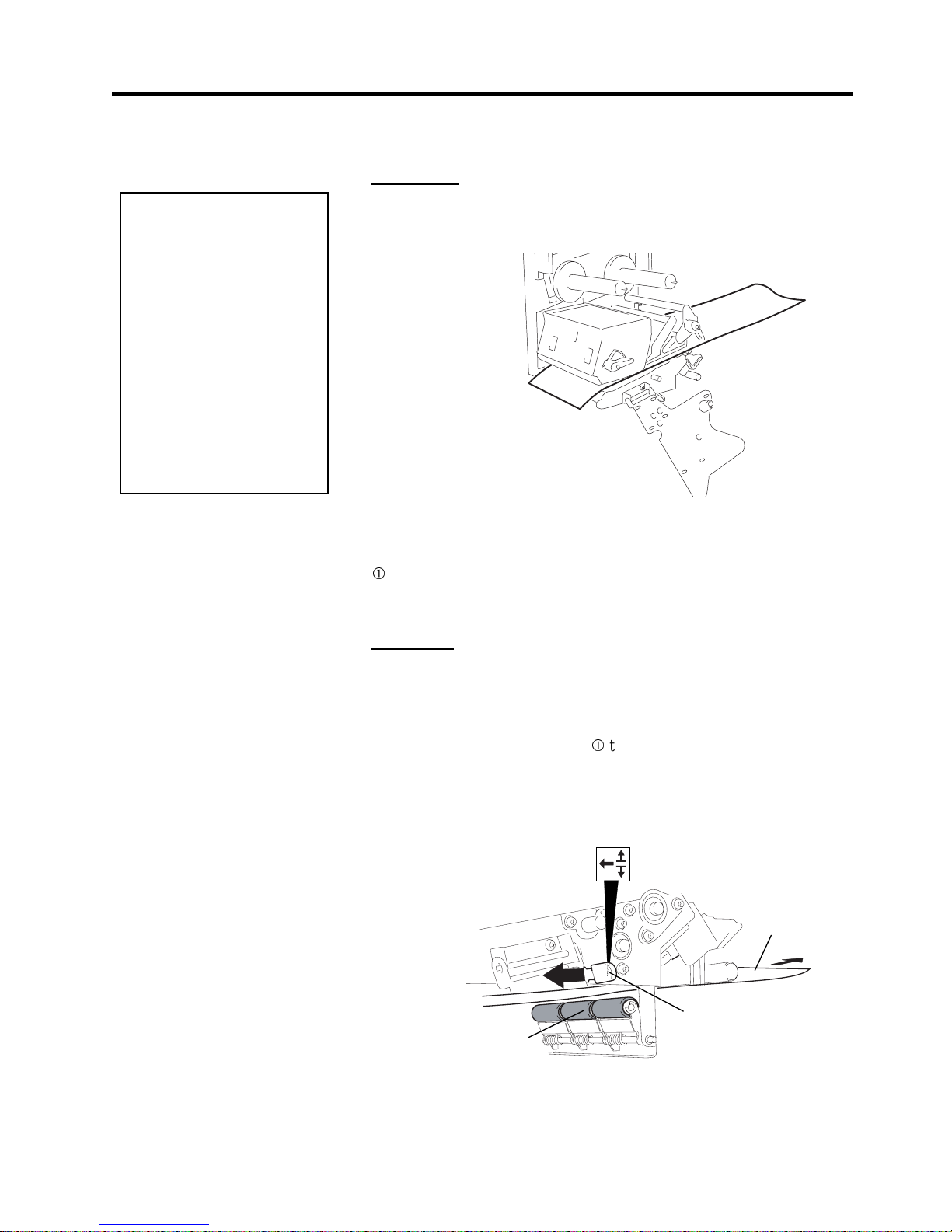
3.
Remove the locking screw to detach the paper guide B from the
printer.
4.
Push the pinch roller release lever toward the front of the printer to
release the strip pinch roller unit.
5.
Wipe the feed roller and pinch rollers with a soft cloth moistened with
alcohol.
6.
Remove dust or paper particles from the black mark and feed gap
sensors using an air blower.
Locking Screw
Paper Guide B
Feed Roller
Pinch Roller
Strip Pinch Roller
Strip Feed Roller

4. MAINTENANCE
EO1-33032
4.1 Cleaning
4- 4
4.1.3 Paper Holder
4.1.4 Covers and Panels
1.
Open the paper entry guide.
2.
Loosen the locking screw and move the media guides toward the
center.
3.
Remove the set screws to detach both paper holders’ upper plates.
4.
Wipe the paper holders’ upper and lower plates with a soft cloth
moistened with alcohol.
Wipe the Cover and Operation Panel with a dry soft cloth. Wipe off dirt
with a soft cloth slightly moistened with water.
Locking Screw
Set Screw
Set Screw
Paper Holders’
Upper Plate
Paper Entry Guide
Paper Holders’ Lower Plate
Loose
CAUTION!
Do not use any volatile
solvents including thinner and
benzene, as this may cause
discoloration or distortion of
the cover.

4. MAINTENANCE
EO1-33032
4.2 Care/Handling of the Media and Ribbon
4- 5
4.2 Care/Handling of the
Media and Ribbon
• Do not store media or ribbon for longer than the manufacturer’s
recommended shelf life
• Store media rolls on the flat end. Do not store them on the curved
sides as this might flatten that side causing erratic media advance and
poor print quality.
• Store the media in plastic bags and always reseal after opening.
Unprotected media can get dirty and the extra abrasion from the dust
and dirt particles will shorten the print head life.
• Store the media and ribbon in a cool, dry place. Avoid areas where
they would be exposed to direct sunlight, high temperature, high
humidity, dust or gas.
• The thermal paper used for direct thermal printing must not have
specifications which exceed Ca
2+
, K+, Na+ 800 ppm, and Cl- 600 ppm.
• Some ink used on pre-printed media may contain ingredients which
shorten the print head’s product life. Do not use labels pre-printed
with ink which contain hard substances such as carbonic calcium
(CaCO
3
) and kaolin (Al2O3, 2SiO2, 2H2O).
For further information, please contact your local distributor or your
media and ribbon manufacturers.
CAUTION!
Be sure to carefully review an
d
understand the Supply
Manual. Use only media and
ribbons which meet specified
requirements. Use of nonspecified media and ribbons
may shorten the head life and
result in problems with bar
code readability or print
q
uality. All media and ribbons
should be handled with care to
avoid any damage to the
media, ribbons or printer.
Read the guideline in this
section carefully.

5. TROUBLESHOOTING
EO1-33032
5.1 Error Messages
5- 1
5. TROUBLESHOOTING
This chapter lists the error messages, possible problems, and their solutions.
5.1 Error Messages
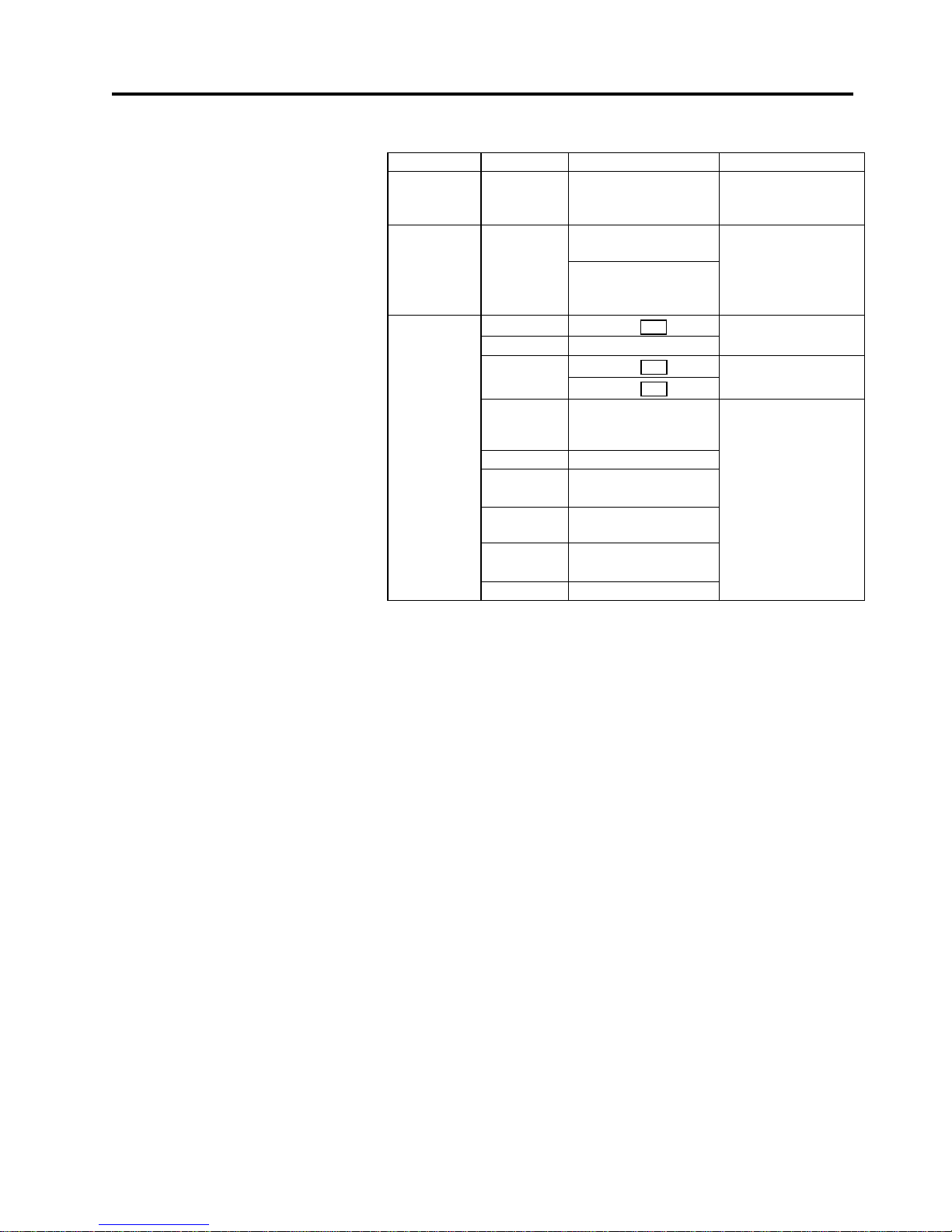
Error Messages Problems/Causes Solutions
HEAD OPEN
The print head block is opened in Online
Mode.
Close the print head block. Then press
the
[RESTART]
key.
HEAD OPEN
****
Feeding or printing has been attempted
with the Print Head Block open.
Close the print head block. Then press
the
[RESTART]
key.
COMMS ERROR
A communication error has occurred. Make sure the interface cable is correctly
connected to the printer and the host, and
the host is turned on. Then press the
[RESTART]
key.
PAPER JAM ****
1. The media is jammed in the media
path. The media is not fed smoothly.
2.
A wrong media sensor is selected for
the media being used.
3.
The Black Mark Sensor is not
correctly aligned to the Black Mark
on the media.
4.
Size of the loaded media is different
from the programmed size.
5.
The Feed Gap Sensor cannot
distinguish the print area from a
label gap.
1.
Remove the jammed media, and clean
the platen. Then reload the media
correctly. Finally press the
[
RESTART]
key.
2.
Turn the printer off and then on. Then
select the media sensor for the media
being used. Finally resend the print
job.
3.
Adjust the sensor position. Then press
the
[RESTART]
key.
4.
Replace the loaded media with one
that matches the programmed size
then press the
[RESTART]
key, or
turn the printer off and then on, select
a programmed size that matches the
loaded media. Finally resend the print
job.
5.
Refer to Section 6.4 to set the
threshold. If this does not solve the
problem, turn off the printer, and call
an authorized service representative.
NO PAPER ****
1. The media has run out.
2.
The media is not loaded properly.
3.
The media is slack.
1.
Load new media. Then press the
[RESTART]
key.
2.
Reload the media correctly. Then
press the [
RESTART]
key.
3.
Take up any slack in the media.
RIBBON ERROR ****
The ribbon is not fed properly.
Remove the ribbon, and check the status
of the ribbon. Replace the ribbon, if
necessary. If the problem is not solved,
turn off the printer, and call an authorized
service representative.
N
OTES:
•
If an error is not cleared by pressing the
[RESTART]
key, turn the printer off and then on.
•
After the printer is turned off, all print data in the printer is cleared.
•
“****”
indicates the remaining number of labels to be printed. Up to 9999 (pieces)
WARNING!
If a problem cannot be solved by taking actions described in this chapt er , do not attempt to repair th
e
printer. Turn off and unplug the print er . Then contact an authorized TOSHIBA TEC service
representative for assistance.

5. TROUBLESHOOTING
EO1-33032
5.2 Possible Problem s
5- 2
5.1 Error Messages (Cont.)
Error Messages Problems/Cause Solutions
NO RIBBON ****
The ribbon has run out. Load a new ribbon. Then press the
[RESTART]
key.
EXCESS HEAD TEMP
The print head has overheated. Turn off the printer, and allow it to cool
down (for about 3 minutes). If this does
not solve the problem, call a TOSHIBA
TEC authorized service representative.
HEAD ERROR
There is a problem with the Print Head. Replace the Print Head. Then press the
[RESTART]
key.
COVER OPEN ****
Media feed or print operation is
attempted with the top cover opened.
Close the top cover, then press the
[RESTART]
key.
PINCH OPEN ****
Media feed or print operation is
attempted with the pinch roller raised.
Set the pinch roller, then press the
[RESTART]
key.
PEEL OPEN ****
Media feed or print operation is
attempted with the strip pinch roller unit
opened.
Close the strip pinch roller unit, then press
the
[RESTART]
key.
GUIDE OPEN ****
Media feed or print operation is
attempted with the media guide plate
removed.
Set the media guide plate, then press the
[RESTART]
key.
Other error messages A hardware or software problem may
have occurred.
Turn the printer off and then on. If this
does not solve the problem, turn off the
printer again, and call a TOSHIBA TEC
authorized service representative.
5.2 Possible Problems
This section describes problems that may occur when using the printer, and their causes and solutions.
Possible Problems Causes Solutions
The printer will not
turn on.
1. The AC Power Cord or DC Power
Cord is disconnected.
2. The AC outlet is not functioning
correctly.
3. The fuse has blown, or the circuit
breaker has tripped.
1. Plug in the AC Power Cord or DC
Power Cord.
2. Make sure that the power is supplied
using another electric appliance.
3. Check the fuse or breaker.
The media is not fed. 1. The media is not loaded properly.
2. The printer is in an error condition.
1. Load the media properly.
2. Solve the error in the Message
Display. (See Section 5.1 for more
detail.)
Nothing is printed on
the media.
1. The media is not loaded properly.
2. The ribbon is not loaded properly.
3. A print head is not installed properly.
4. The ribbon and media are not
matched.
1. Load the media properly.
2. Load the ribbon properly.
3. Install the Print Head properly. Close
the Print Head Block.
4. Select an appropriate ribbon for the
media type being used.
The printed image is
blurred.
1. The ribbon and media are not
matched.
2. The Print Head is not clean.
1. Select an appropriate ribbon for the
media type being used.
2. Clean the print head using a Print
Head Cleaner.

5. TROUBLESHOOTING
EO1-33032
5.3 Removing Jamm ed Media
5- 3
5.3 Removing Jammed
Media
5.4 Threshold Setting
This section describes in detail how to remove jammed media from the
printer.
1.
Open the top cover.
2.
Turn the head lever and the pinch roller lever to position d, then open
the ribbon shaft holder plate.
3. Pull out the media guide plate from the printer side.
4. Remove the ribbon and media.
5. Remove the jammed media from the printer. DO NOT USE any sharp
implements or tools as these could damage the printer.
To maintain a constant print position the printer uses the Transmissive
Sensor to detect the gap between labels by measuring the amount of light
passing through the media. When the media is pre-printed, darker (or
more dense) inks can interfere with this process causing paper jam errors.
To get around this problem a minimum threshold can be set for the sensor
in the following way.
Threshold setting procedure
1. Turn the power ON. The printer is in stand by mode.
2. Load the media.
3. Press the [PAUSE] key.
4. The printer enters the pause mode.
5. Press and hold the [PAUSE] key for at least 3 seconds in the pause
state.
6. The sensor type is displayed.
7. Select the sensor to be adjusted by pressing the [FEED] key.
CAUTION!
Do not use any tool that
may damage the print
head.
NOTES:
1. If the
[PAUSE]
key is
released within 3 seconds
while in the pause state, the
paper will not feed.
2. Failure to feed more than
1.5 labels may result in an
incorrect threshold setting.
3. While the Print Head Block
is raised, the
[PAUSE]
key
does not work.
4. A paper end error cannot
be detected during paper
feed.
5. Selecting the Transmissive
Sensor (for pre-printed
labels) within software
commands allows the
printer to detect the proper
print start position even
when using pre-printed
labels.
6. If using the transmissive
sensor and the printer
continues to print out of
position even after setting
the threshold, adjust the
Feed Gap Sensor in the
system mode. Reset the
threshold again. Make sure
that the Transmissive
Sensor (for pre-printed
labels) is selected in the
feed and issue commands.
21 /,1(
3$86(
75$160,66,9(
5()/(&7,9(
75$160,66,9(
[FEED] key
Black Mark Sensor
Feed Gap Sensor

5. TROUBLESHOOTING
EO1-33032
5.4 Threshold Setting
5- 4
5.4 Threshold Setting
(Cont.)
8.
Press and hold the
[PAUSE]
key until more than 1.5 labels have
been issued.
The media will continue to be fed until the
[PAUSE]
key is
released.
(Threshold setting for the selected sensor is completed by this
operation.)
9.
Press the
[RESTART]
key.
10.
The printer is in stand-by.
11.
Send an issue command from the PC to the printer.
3$86(
21 /,1(
21 /,1(

6. PRINTER OPERATION
EO1-33032
6.1 Overview
6- 1
6. PRINTER OPERATION
6.1 Overview
6.2 Installing the Printer
Drivers
This section provides a functional overview of how the printer receives
print data from your host computer and how it will operate in the various
operating conditions. This section also shows you how to install the TEC
Printer Drivers into your computer.
Labels will be created on the host computer connected to your printer,
using either a commercially available label creation program or using the
TEC Command Program Language. The label information sent from
your host computer will consist of a series of commands that inform the
printer of the labels size, layout, orientation, and number of copies to
print and will also contain the print data including scaleable text,
graphics, and bar codes. The printer electronics will decode the
commands and manipulate the data to create a bit graphic image of the
label that will be stored in the printer’s memory. The printer electronics
will then transfer the image as a series of dots, one line at a time, to the
thermal print head.
The thermal print head consists of a line of 1280 thermal elements with
each element shaped like a tiny dot. The dot line is 4 inches (101.6 mm)
in length resulting in a dot density of 305 DPI. As the paper is advanced
through the printer by the paper feed mechanism, the thermal head
continuously prints the image as a series of dot lines at a resolution of
305 dots per inch, horizontally and vertically.
Precision feeding and back feeding of the label stock is accomplished
through the use of specialized stepping motors and photo-sensors. The
label gap sensor or the black mark sensor tells the printer electronics
when the label stock is properly positioned under the head for accurate
printing.
Before you can use the printer, it is necessary to install the printer driver
to your PC. Installation is accomplished by first installing the set of
printer driver files from the supplied CD-ROM.
Run the following SETUP.EXE.
“X”:\DRIVE\SETUP.EXE
The latest printer driver can be obtained from the TOSHIBA TEC
Barcode Web Site. Access the TOSHIBA TEC Barcode World Wide
Web Site at the following URL:
http://barcode.toshibatec.co.jp/Eng/download.html
Double click on the downloaded file (“Bdrv_Vx_x_Buildxx.exe”), and
then run the following SETUP.EXE. (“C:\TEC\MONO\CD”is the
default install directory.)
“C:\TEC\MONO\CD”\SETUP.EXE
NOTE:
“X” will be replaced with your
CD drive’s letter. (e.g. D, E, etc.)
NOTE:
1. When downloading the
printer driver from TEC Web
Site, confirm the version and
use the latest printer driver.
The supplied CD-ROM
contains
‘Bdrv_V6_5_Build77.exe”.
2. Driver file name, capacity,
and date of the driver may be
changed without prior
notification. For the latest
information about the driver,
please contact your
authorised TOSHIBA TEC
representative.

6. PRINTER OPERATION
EO1-33032
6.2 Installing the Print er Dri vers
6- 2
6.2.1 System Requirements
6.2.2 Driver Installation
1.
System
a. IBM Compatible PC running Windows 95® or Windows 98® or
Windows NT® Version 4.0 Workstation, Windows NT® Version
4.0 Server, Windows 2000® Professional, or Windows 2000®
Server.
b. Pentium® processor, 133MHz or greater recommended.
c. Installed memory of 16MB minimum (32MB recommended).
d. Available Hard Disk space of 10MB or more.
2.
Interface
a. The RS-232C interface
b. Centronics interface
1.
Insert the supplied CD-ROM into the CD drive of your PC.
2.
Click on the
START
button, then select and click on the
Run…
.
3.
Type in ‘D:\DRIVER\SETUP.EXE” and click on the OK button.
(“D” may be replaced with your CD drive’s letter.)
4.
The screen will change as shown below.
5.
After the Install Shield temporary files have been loaded, the display
will change to the Welcome screen as shown below.
NOTE:
Windows 3.1® is not supported.
Windows 3.1®, Windows 95®,
Windows 98®, Windows NT®
,
and Windows 2000 ®
are
registered trademarks of
M
icrosoft Corporation.
Pentium® is a registered trademark of Intel Corporation
NOTE:
1. How to install the printer
driver from the supplied CDROM is described below.
2. When the printer driver is
downloaded from TOSHIBA
TEC Web Site, type in
“C:\TEC\MONO\CD\SETUP
.EXE”. C:\TEC\MONO\CD
is the default install directory
generated when the printer
driver file
(Bdrv_Vx_x_Buildxx.exe) is
run.

6. PRINTER OPERATION
EO1-33032
6.2 Installing the Print er Dri vers
6- 3
6.2.2 Driver Installation
(Cont.)
6.
Click on the
Next
button to continue the installation. The screen will
change to the Software License Agreement screen.
7.
Carefully read the Software License Agreement. To accept the
conditions of the agreement, click on the
Yes
button. If you do not
accept the conditions click on the No button.
8.
Upon clicking on the Yes button, the screen will change to list the
available TEC driver sets. For this printer, select “TEC B-492” and
click on the
Next
button.
9.
The screen will change to the following.
When the printer is directly connected to this PC, select “Local
Printer”, otherwise, select “Network Printer”. Then click on the
Next
button.
NOTE:
I
f you click on the No button
in the License Agreement
screen, the program will not
be installed.

6. PRINTER OPERATION
EO1-33032
6.2 Installing the Print er Dri vers
6- 4
6.2.2 Driver Installation
(Cont.)
If you selected the Local Printer in the previous step, go to Step 10.
If you selected the Network Printer in the previous step, go to Step 11.
10.
When you selected the Local Printer in Step 9, select the PC port to
which this printer is connected.
11.
When you selected the Network Printer in Step 9, enter a network
path, and click on the
Next
button. If the network path is unknown,
click on the
Browse…
button and select the same printer that you
chose in Step 8.
12.
The screen will show the selected printer name. Change the printer
name, if necessary.
NOTE:
B
e sure to select the same printer
that you are going to install.
NOTE:
I
f you specify the same name as
already installed printer, that
p
rinter will be overwritten.
When you desire to install the
same printer for many times,
change the printer name each
time.

6. PRINTER OPERATION
EO1-33032
6.2 Installing the Print er Dri vers
6- 5
6.2.2. Driver Installation
(Cont.)
13.
Upon clicking on the
Next
button on the previous screen, the printer
driver files copy will start.
14.
After all of the files have been transferred the display will change to
the Setup Complete screen. Select “Yes, I want to restart my
computer now.”, then click on the
Finish
button.
15.
After the TEC Printer Driver has been successfully loaded, the
Printers screen should appear as shown below, showing the TEC B492 as being successfully installed.

6. PRINTER OPERATION
EO1-33032
6.2 Installing the Print er Dri vers
6- 6
6.2.3 Uninstalling the TEC
B-492 Printer Driver
If it becomes necessary to remove the TEC-B-492 printer driver from
your host computer, then it can be removed as follows.
1.
Access the Windows Control Panel and click on the
Add/Remove
Programs
icon.
2.
Select “TEC B-492 Printer” and click on the
Add/Remove
button.
3.
When the following screen appears, click on the
Yes
button.
4.
When the Registration information deletion screen appears, click on
the
Yes
button if you desire to delete the paper information. If you do
not desire to delete the information, click on No button.
If this message does not appear, go to the next step.
NOTES:
I
f the registration information is
deleted, the registered labels will
not be able to be used when the
p
rinter driver is re-installed.

6. PRINTER OPERATION
EO1-33032
6.2 Installing the Print er Dri vers
6- 7
6.2.3 Uninstalling the TEC
B-492 Printer Driver
(Cont.)
5.
When the following screen appears, click on the
Yes To All
button.
If this screen does not appear, the screen of Step 7 will appear instead.
6.
Upon clicking on the
Yes To All
button, the following screen appears
to confirm the deletion of shared file. Click on the
Yes
button.
7.
Printer driver deletion starts. When the deletion is completed, click on
the OK button.
NOTE:
D
eleting the shared files does
not affect other programs.
NOTE:
Please note that it may take time
to delete the printer driver.

APPENDIX 1 SPECIFICATIONS
EO1-33032
A1.1 Printer
A1- 1
APPENDIX 1 SPECIFICATIONS
Appendix 1 describes the printer specifications and supplies for use on the B-492L/R printer.
A1.1 Printer
The following are the printer specifications.
Model
Item
B-492L/R-TH10-QQ B-492L/R-TH10-QP
AC120V, 60 Hz
1.3 A, 123 W maximum
0.17 A, 22 W maximum
AC220 to 240V, 50Hz
0.7A, 126W maximum
0.06A, 24W maximum
Supply voltage
Power consumption
During a print job
During standby
Operating temperature range
Relative humidity
Resolution
Printing method
Printing speed
Thermal transfer printing
Thermal direct printing
Available media width (including
backing paper)
Effective print width (max.)
Product type
LCD Message display
Dimension (W × D × H)
Weight
Available bar code types
Available two-dimensional code
Available bar font
Rotations
Standard interface
5°C to 40°C (40°F to 104°F)
25% to 85% RH (no condensation)
12 dots/mm (305 dpi)
Thermal transfer or Thermal direct
127 mm/sec. (5”/sec.), 203.2 mm/sec. (8”/sec.), 254 mm/sec. (10”/sec.)
101.6 mm/sec. (4”/sec.), 127 mm/sec. (5”/sec.), 203.2 mm/sec. (8”/sec.)
20 mm to 112 mm (0.8”to 4.4”)
104.0±0.2 mm (4.1”)
B-492L: for a left flow line, B-492R: for a right flow line
16 characters/line
329 mm × 245 mm × 300 mm (13.0” × 9.6” × 11.8”)
Depth of the PCB block: 125 mm (4.9”)
13 kg (28.7 lb) (Excluding Media and ribbon)
JAN8, JAN13, EAN8, EAN8+2 digits, EAN8+5 digits,
EAN13, EAN13+2 digits, EAN13+5 digits UPC-E, UPC-E+2 digits, UPCE+5 digits, UPC-A, UPC-A+2 digits, UPC-A+5 digits MSI, ITF, NW-7,
CODE39, CODE93, CODE128 EAN128, Industrial 2 to 5, Customer Bar
Code, POSTNET, KIX CODE, RM4SCC (ROYAL MAIL 4STATE
CUSTOMER CODE)
Data Matrix, PDF417, QR code, Maxi Code, Micro PDF417
Times Roman (6 sizes), Helvetica (6 sizes), Presentation (1 size), Letter
Gothic (1 size), Prestige Elite (2 sizes), Courier (2 sizes), OCR (2 types),
Outline font (4 types), Price font (3 types)
0°, 90°, 180°, 270°
Serial interface (RS-232C)
Parallel interface (Centronics)
Keyboard interface
Expansion I/O interface
Optional interface PCMCIA interface (B-7708-PC-QM)
N
OTES:
•
Data Matrix
TM
is a trademark of International Data Matrix Inc., U.S.
•
PDF417
TM
is a trademark of Symbol Technologies Inc., US.
•
QR Code is a trademark of DENSO CORPORATION.
•
Maxi Code is a trademark of United Parcel Service of America, Inc., U.S.

APPENDIX 1 SPECIFICATIONS
EO1-33032
A1.2 Options
A1- 2
A1.2 Options
Option Name Type Description Source
Keyboard module KB-80-QM This module is an external intelligent keyboard unit,
including a 16 digit by 2 line LCD and 28 key
switches.
See NOTE.
PCMCIA interface
board
B-7708-PC-QM This board enables the use of the following
PCMCIA cards:
LAN card: 3 COM EtherLink® III (recommended)
ATA card: Conforming to PC card ATA standard
Flash memory card: 4MB card (See page 2-13.)
See NOTE.
A1.3 Media
Please make sure that the media to be used is approved by TOSHIBA TEC. The warranties do not apply to
problems caused by using media that is not approved by TOSHIBA TEC.
For information regarding TOSHIBA TEC-approved media, please contact a TOSHIBA TEC authorized service
representative.
A1.3.1 Media Type
This thermal transfer/direct thermal printer is specifically designed for label media. The table below shows the
size and shape of the media available for this printer.
N
OTE:
A
vailable from your nearest TOSHIBA TEC representative or TOSHIBA TEC Head Quarters.
e
f
h
c
d
i
g
Stop
position
Feed Direction
Black Mark
(on reverse side) Refer to
NOTE 3 below.

APPENDIX 1 SPECIFICATIONS
EO1-33032
A1.3 Media
A1- 3
A1.3.1 Media Type (Cont.)
Unit: mm+(inch)
Label dispensing mode
Item
Batch mode Strip mode
c
Width including backing paper 20 to 112 (0.8 to 4.4)
d
Label width Min. 17 (0.7)
e
Label pitch 12 to 999 (0.5 to 39.3)
12 to 999 (0.5 to 39.3)
10 ips: 25.4 to 999 mm (1 to 39.3)
f
Label length Min. 10 (0.4)
Min. 10 (0.4)
10 ips: Min. 23.4 (0.9)
g
Gap length (or black mark length) 2 to 20 (0.08 to 0.8)
h
Black mark width Min. 12 (0.5)
Thickness 0.13 to 0.18 (0.005 to 0.007)
Max. outer roll diameter
φ
200 (Reference value, See NOTE 6.)
Roll direction Inside rolled paper is recommended.
Inner core diameter 76.2±0.3 (3±0.01) (Reference value)
A1.3.2 Detection Area of the Transmissive Sensor
The transmissive sensor is movable from the center to the left edge of the media.
The transmissive sensor detects gaps between labels, as illustrated below.
N
OTES:
1. To ensure print quality and print head life use only TOSHIBA TEC approved media.
2. For the backing paper Glassine paper 7K white or equivalent should be used. Also, the light transmission
rate of the backing paper should be 22% or above.
3. When perforating the media, it should be done from the print side to the reverse side.
4. Ink used for pre-printing the media should not contain hard substances such as carbonic calcium (CaCO
3
)
and Kaolin (Al
2O3
, 2SiO2, 2H2O).
5. The reflectance of the black mark should be 10% or less when the wavelength is 950nm.
6. As this printer does not have a label holder, this figure is a guide for the system integrator using this printer.
When the outer roll diameter of the labels being used is 200 mm or less, a hanging type supply holder
similar to the type used in TEC desktop thermal printer’s will work correctly. When the outer roll diameter
exceeds 200 mm, the label holder should have mechanisms, such as bearings, a damper, etc. to reduce the
tension on the label. In any case, prior to actual operation, please be sure to test all practical conditions
including the labels, system, etc. and confirm there is no problem.
Sensor position
Area to be detected.
Center of media
Print side
Min. 12 mm
Label
Gap
Label
2 to 20 mm
Sensor is movable
within this range.
Media feed direction

APPENDIX 1 SPECIFICATIONS
EO1-33032
A1.3 Media
A1- 4
A1.3.3 Detection Area of the Reflective Sensor
The reflective sensor is movable from the center to the left edge of media.
The reflection factor of the black mark must be 10% or lower with a waveform length of 950 nm.
The reflective sensor should be aligned with the center of the black mark.
A1.3.4 Effective Print Area
The figure below illustrates the relation between the head effective print width and media width.
The figure below shows the effective print area on the media.
Sensor should be positioned at
the center of the black mark.
Center of media
Min. 12 mm
Media feed direction
2 to 20 mm
Sensor is movable
within this range.
N
OTES:
1. Avoid printing in the area 1.5-mm wide from the media edges (shaded area in the above figure).
2. The center of media is positioned at the center of the print heads.
3. Print quality is not guaranteed within 3 mm from the print head stop position (including 1-mm slowup).
4. Average print (black) rate should be 15% or less. For bar code print area, the print rate should be 30%
or less.
5. Line weight should be 3 to 12 dots.
Detecting the blac
k
marks on the back.
Start line
Area to be detected.
Area to be detected.
Media feed direction
1.5 mm from the
left edge of
media
Media width
(backing paper width is not included.)
1.5 mm from the right
edge of media
1 mm
1 mm
Guaranteed print area
Print Head Element
Out of print rangeOut of print range
2.7
mm
2.7
mm
104.0 mm ± 0.2 mm
(Head Effective Print Range)
112.0 mm (Maximum paper width)

APPENDIX 1 SPECIFICATIONS
EO1-33032
A1.4 Ribbon
A1- 5
A1.4 Ribbon
Please make sure that the ribbon being used is approved by TOSHIBA TEC. The warranties do not apply to any
problem caused by using non-approved ribbons.
For information regarding TOSHIBA TEC approved ribbon, please contact a sales representative.
Type Spool type
Width 41 – 112 mm (1.6” to 4.4”)
41, 68, 84 and 112 mm (1.6”, 2.7”, 3.3”, 4.4”) are recommended.
Length 600 +10, -0 m (Max.)
Outside Diameter φ90 mm (φ3.5”) (Max.)
NOTES:
1. To ensure print quality and print head life use only TOSHIBA TEC specified ribbons.
2. To avoid ribbon wrinkles use a ribbon which is the correct width for each media width used.
It is possible to use narrower ribbons than media width, however, the effective print width also narrows
Ribbon width 41 mm 68 mm 84 mm 112 mm
Proper media width 20 to 36 mm 36 to 63mm 63 to 79 mm 79 to 112mm

APPENDIX 2 MESSAGES AND LEDS
EO1-33032
APPENDIX 2 MESSAGES AND LEDS
A2- 1
APPENDIX 2 MESSAGES AND LEDS
Appendix 2 describes the LCD messages displayed on the operation panel.
Symbols in the message
1: : The LED is illuminated. ~: The LED is flashing. z: The LED is unlit.
2: ****: the remaining number of labels to be printed. Up to 9999 (pieces)
3: %%%%%%%: ATA Card’s remaining memory 0 to 9999999 (in K bytes)
4: ###: Flash memory card remaining memory for PC save area: 0 to 895 (in K bytes)
5: &&&&: Remaining flash memory capacity for storing writable characters 0 to 3147 (in K bytes)
LED Indication
No.
LCD Message
POWER ONLINE ERROR
Printer Status
Restoration
by RESTART
key Yes/No
Acceptance of
Status Request
Reset Comman
d
Yes/No
21 /,1(
z
In online mode ----- Yes
1
21 /,1(
~
z
In online mode (The printer is receiving
a communication)
----- Yes
2
+($' 23(1
z
z
The print head block is opened in online
mode.
----- Yes
3
3$86(
z
z
The printer is paused. Yes Yes
4
&2006 (5525
z
A parity, overrun, or framing error has
occurred during communication through
the RS-232C port.
Yes Yes
5
3$3(5 -$0
z
The media has jammed during feed. Yes Yes
6
12 3$3(5
z
The media has run out, or the media is
not loaded correctly.
Yes Yes
7
5,%%21 (5525
z
The ribbon has run out, or has snapped.
A problem has occurred with the sensor
that determines the torque for the ribbon
motor .
Yes Yes
8
+($' 23(1
z
Feeding or printing was attempted with
the print head block open.
Yes Yes
9
&29(5 23(1
z
Feeding or printing was attempted with
the top cover open.
Yes Yes
10
3,1&+ 23(1
z
Feeding or printing was attempted with
the pinch roller raised.
Yes Yes
11
3((/ 23(1
z
Feeding or printing was attempted with
the strip pinch roller unit open.
Yes Yes
12
*8,'( 23(1
z
Feeding or printing was attempted with
the media guide plate removed.
Yes Yes
13
(;&(66 +($' 7(03
z
The print head has overheated. No Yes
14
6$9,1*
RU
6$9,1*
z
In writable character or PC command
save mode
----- Yes
15
)/$6+ :5,7( (55
z
An error has occurred while formatting
the flash memory or ATA card.
No Yes
16
)250$7 (5525
z
An erase error has occurred in
formatting the flash memory or ATA
card.
No Yes
17
)/$6+ &5' )8//
z
Data cannot be stored because the flash
memory or ATA card is full.
No Yes
18
+($' (5525
z
There is a problem with the print head. Yes Yes
19
Display of error
message (See Notes.)
z
The data analyzer has found an error in
the displayed command.
Yes Yes

APPENDIX 2 MESSAGES AND LEDS
EO1-33032
APPENDIX 2 MESSAGES AND LEDS
A2- 2
N
OTES:
• If a corrupt command is received, the first 16 bytes of the command, starting from the command code, will be
displayed. (However, [LF] and [NUL] will not be displayed.)
Example 1
[ESC] PC001;0A
00,0300,2,2,A,00,B [LF] [NUL]
Corrupt data
The following message appears.
Example 2
[ESC] XR; 0200, 0300, 0450, 1200, 1
, [LF] [NUL]
Command error
The following message appears.
Example 3
[ESC] T20E 30 [LF] [NUL]
Corrupt data
The following message appears.
• The character “? (3FH)” is displayed for character codes outside the ranges 20H to 7FH and A0H to DFH.
3&$
;5
7(

APPENDIX 3 INTERFACE
EO1-33032
APPENDIX 3 INTERFACE
A3-1
APPENDIX 3 INTERFACE
Interface Cables
To prevent radiation and reception of electrical noise, the interface cables must meet the following
requirements:
• Fully shielded and fitted with metal or metallized connector housings.
• Keep as short as possible.
• Should not be bundled tightly with power cords.
• Should not be tied to power line conduits.
RS-232C Cable description
The serial data cable used to connect the printer to a host computer should be one of the following two
types:
N
OTE:
Use an RS-232C cable with inch type securing screws on the connector.
DB-9S
Connector to PC
Pin No. Signal
1 N.C.
2 RXD
3 TXD
4 DTR
5 GND
6 DSR
7 RTS
8 CTS
9 N.C.
Housing Shield
DB-9P
Connector to Printer
Pin No. Signal
1 N.C.
2 TXD
3 RXD
4 DSR
5 SG
6 DTR
7 CTS
8 RTS
9 N.C.
Housing Shield
DB-25S
Connector to PC
Pin No. Signal
1 Shield
2 TXD
3 RXD
4 RTS
5 CTS
6 DSR
7 GND
20 DTR
DB-9P
Connector to Printer
Pin No. Signal
1 N.C.
2 TXD
3 RXD
4 DSR
5 SG
6 DTR
7 CTS
8 RTS
9 N.C.

APPENDIX 4 SYSTEM MODE
EO1-33032
A4.1 Operation Panel
A4- 1
APPENDIX 4 SYSTEM MODE
A4.1 Operation Panel
Appendix 4 describes usage of the keys on the Operation Panel in System
Mode.
For end users, System Mode should be used for the following five
purposes:
• To reset the printer. (Reset mode)
• To check and print the system status, the Maintenance Counter, and
to check the Print Head Elements.
• To make fine adjustment to the media handling.
• To perform a test print for checking print quality.
• To print the raw data being received by the printer (Dump mode).
The figure below shows the Operation Panel and key functions.
The LCD Message Display shows messages to indicate the printer’s
current status. Up to 16 characters can be displayed on this line.
There are three LEDs on the Operation Panel.
LED Illuminates when…
POWER
The printer is turned on.
ON LINE
The printer is ready to print.
ERROR
Any error occurs on the printer.
In System Mode, the
[FEED], [RESTART]
and
[PAUSE]
keys
function as described below.
FEED
Used to navigate the parameter mode or to fine adjust
the parameters in the negative direction (- Down).
RESTART
Used to release the printer from Pause condition, to
navigate the parameter mode, or to fine adjust the
parameters in the positive direction (+ Up).
By pressing and holding the
[RESTART]
key in Pause
condition for more than 3 sec., the printer enters the
system mode.
PAUSE
Used to stop printing operation temporarily, to select
the parameter mode, or used as an enter key.
By pressing and holding the
[PAUSE]
key in Pause
condition for more than 3 sec., the printer enters the
threshold setting mode.
IMPORTANT!
I
f System Mode is needed for
any other purposes, please
contact a TOSHIBA TEC
authorized service
representative before
p
erforming any operation in
System Mode.
NOTE:
Use the
[RESTART]
key to
resume printing after a pause
condition, or after clearing an
error.
FEED RESTART PAUSE
POWER ON LINE ERROR
LCD Message Display
ON LINE LED (Green)
ERROR LED (Red)
[PAUSE] key
POWER LED
(Green)
[FEED] key
[RESTART] key

APPENDIX 4 SYSTEM MODE
EO1-33032
A4.2 Overview
A4- 2
A4.2 Overview
The System Mode consists of nine main menu items: Reset, SelfDiagnostic Test, Parameter Setting, Printer Parameter Fine Adjustment,
Test Print, Sensor Adjustment, RAM Clear, IP Address Setting, and
Dump mode.
Press the
[PAUSE]
key so that the printer enters the Pause condition.
Then, press and hold the
[RESTART]
key until “<0>RESET” appears on
the display.
NOTE:
1. To navigate the System Mode
menus the
[RESTART]
and
[FEED]
key can be used.
2. Pressing the
[PAUSE]
key
will enter the sub menus of
each System Mode menu.
Flowcharts of each sub menu
are provided on the following
pages.
[FEED]
[FEED]
[FEED]
[FEED]
This leads to the Self-Diagnostic
Test menu.
This leads to the Printer Parameter
Fine Adjustment menu.
This leads to the Test Print menu.
This will Reset the printer.
[RESTART]
[RESTART]
[RESTART]
[RESTART]
!',$* 9[[
!$'-867 6(7
!7(67 35,17
IMPORTANT!
The
following menus are for
Service Personnel only:
<2>PARAMETER SET
<5>SENSOR ADJ.
<6>RAM CLEAR
<7>IP ADDRESS
Please do not change the
settings for these items, as
doing so may cause the
p
rinter to malfunction.
I
f you should accidentally
enter these System Modes, to
exit just turn the power off. I
f
y
ou should change any of the
settings by accident and the
p
rinter malfunctions, please
contact your nearest
TOSHIBA TEC service
representative.
!5(6(7
!3$5$0(7(5 6(7
!6(1625 $'-
!5$0 &/($5
!,3 $''5(66
!'803 02'(
[FEED]
[FEED]
[FEED]
[FEED]
[RESTART]
[RESTART]
[RESTART]
[RESTART]
[RESTART]
[FEED]
This leads to the Parameter Setting
menu.
This leads to the Sensor Adjustment
menu.
This leads to the RAM Clear menu.
This leads to the IP Address Setting
menu.
This leads to the DUMP mode menu.

APPENDIX 4 SYSTEM MODE
EO1-33032
A4.3 Reset Mode
A4- 3
A4.3 Reset Mode
A4.4 Self-Diagnostic
Test
The Reset operation clears all the print data that has been sent to the
printer from the computer, and returns the printer to an idle condition.
1.
The printer is on, standing by, or printing.
2.
To stop printing, or clear the data sent from the computer, press the
[PAUSE]
key. The printer stops printing.
3.
Press and hold the
[RSTART]
key for 3 seconds or longer.
4.
Press
[PAUSE]
key. All data that has been received sent from the
computer will be cleared, and the printer returns to an idle condition.
The Self-Diagnostic Test contains the following sub menus:
21 /,1(
3$86(
!5(6(7
21 /,1(
NOTE:
I
f the
[RESTART]
key is held for
less than 3 seconds when the
p
rinter is in an error or pause
state, the printer will restart
p
rinting. However, when a
communication error or
command error occurs, the
p
rinter will return to an idle
condition.
[PAUSE]
[PAUSE]
[FEED]
[FEED]
[RESTART]
[RESTART]
[FEED]
Select the ribbon type
Print out the Maintenance Counter
and Parameter Settings.
Perform a Self-Diagnostic Test, and
prints out the result.
Check to see if there is any problem
with the print head.
!',$* 9[[
$872 ',$*1267,&
0$,17(1$1&( &217
+($' &+(&.
5,%%21 75$16
[RESTART]
Outline of Self-Diagnostic Test
I
n the Self-Diagnostic Test
mode
, the printer checks and
p
rints out the printer system
information such as the sensor
or interface, and the
M
aintenance Counter.
It also
p
erforms the print head
broken element check.
NOTE:
Use the
[FEED]
or
[RESTART]
key to select a desired option.

APPENDIX 4 SYSTEM MODE
EO1-33032
A4.4 Self-Diagnostic Test
A4- 4
A4.4 Self-Diagnostic
Test (Cont.)
While in a Pause condition press and hold the
[RESTART]
key until
“<0>RESET” appears in the display.
Then, press the
[FEED]
key, and “<1>DIAG. Vx.x” message appears.
Ribbon type selection
Press the
[PAUSE]
key. The ribbon type can be selected:
“NO RIBBON” (Direct Thermal Paper), “TRANS.” (Transmissive
ribbon), or “NO TRANS.” (Non transmissive ribbon).
After selecting the ribbon type, press the
[PAUSE]
key to confirm and
go to Maintenance counter and Parameter settings print out.
Maintenance counter/parameter settings print out
The printer will print out the Maintenance Counter and Parameter
Settings. Press the
[PAUSE]
key to start.
The printer starts printing out the Maintenance Counter & Parameter
Settings.
After printing is completed, the display returns to “<1>DIAG. Vx.x”.
Self-Diagnostic Test and the result print out
After the Maintenance Counter and Parameter Settings print out has been
completed, the display returns to “<1>DIAG. Vx.x”. Press the
[PAUSE]
key twice then
[FEED]
key once.
The Self-Diagnostic Test is ready. Press the
[PAUSE]
key to start.
The printer starts the Self-Diagnostic Test, and prints out the result.
After printing is completed, the display returns to “<1>DIAG. Vx.x”.
!5(6(7
5,%%21 75$16
0$,17(1$1&( &217
&+(&.,1* 35,17
NOTE:
When using a ribbon, be sure to
select “TRANS” or “NO
TRANS.”. When using direct
thermal media, be sure to select
“NO RIBBON”.
NOTE:
See Section A4.8.2 for a
M
aintenance Counter and
Parameter Settings print
sample and a detailed
descri
p
tion for each item.
NOTES:
1. If an error occurs, an
error message appears,
and the printer stops
printing. After clearing
the error, press the
[PAUSE]
key to return to
“<1>DIAG.”. The
printer does not resume
printing automatically.
2. See Section A4.8.1 for
Self-Diagnostic Test Print
sample and a detailed
description of each item
.
5,%%21 12 75$16
Transmissive ribbon
Non transmissive ribbon
[RESTART]
[FEED]
5,%%21 12 5,%%21
$872 ',$*1267,&
&+(&.,1* 35,17
!',$* 9[[
Direct thermal paper

APPENDIX 4 SYSTEM MODE
EO1-33032
A4.4 Self-Diagnostic Test
A4- 5
A4.4 Self-Diagnostic
Test (Cont.)
Print head element check
After the Self-Diagnostic Test result has been printed, the display returns
to “<1>DIAG. Vx.x”. Press the
[PAUSE]
key twice then
[FEED]
key
twice.
The printer is ready to check the print head to see if there are any
problems with the print head. Press the
[PAUSE]
key to start.
The printer starts checking the print head.
If there is no problem with the print head, the print head check is
complete. Press the
[PAUSE]
key to return to “<1>DIAG. Vx.x”.
If there is a problem with the print head, the following message is
displayed.
Press the
[PAUSE]
key to return to “<1>DIAG. Vx.x”.
+($' &+(&.
&+(&.,1*
1250$/ (1'
+($' (5525
NOTES:
1. Make sure that the Top
Cover is closed before
starting the print head
check.
2. If “HEAD ERROR”
appears, then some print
head elements may be
damaged. To sustain high
quality printing, please
contact your nearest
TOSHIBA TEC service
representative for the print
head replacement.

APPENDIX 4 SYSTEM MODE
EO1-33032
A4.5 Printer Parameter Fine Adjustment
A4- 6
A4.5 Printer Parameter
Fine Adjustment
The Printer Parameter Fine Adjustment menu contains the following.
!$'-867 6(7
)((' $'- PP
%$&. $'- PP
; $'-867 PP
721( $'-7!
721( $'-'!
5%1 $'-):!
5%1 $'-%.!
7+5(6+2/'5! 9
7+5(6+2/'7! 9
[PAUSE]
[PAUSE]
',6 $'- PP
[PAUSE]
[PAUSE]
[PAUSE]
[PAUSE]
[PAUSE]
[PAUSE]
[PAUSE]
[PAUSE]
[PAUSE]
Feed Len
g
th Fine Adjustment
Strip Position Fine Adjustment
Back Feed Length Fine Adjustment
X Axis Fine Adjustment
Print Tone Fine Adjustment
(Thermal Transfer)
Print Tone Fine Adjustment
(Direct Thermal)
Ribbon Motor Drive Voltage Fine
Adjustment (Rewind Motor)
Ribbon Motor Drive Voltage Fine
Adjustment (Feed Motor)
Threshold Fine Adjustment (Black
Mark Sensor)
Threshold Fine Adjustment (Feed
Gap Sensor)
Outline of Printer Parameter
Fine Adjustment
I
n the Printer Parameter Fine
A
djustment mode, Fine
adjustments can be made for each
p
arameter, like Print tone, Print
start position, Threshold, etc.
which can also be set by PC
commands. This is useful when
using several types of media in
rotation or when the print start
p
osition or strip position requires
some fine adjustment.
3(/ 2)) 63(('
[PAUSE]
Strip Motor Driving Speed Fine
Adjustment

APPENDIX 4 SYSTEM MODE
EO1-33032
A4.5 Printer Parameter Fine Adjustment
A4- 7
A4.5 Printer Parameter
Fine Adjustment
(Cont.)
While in a Pause condition press and hold the
[RESTART]
key until
“<0>RESET” appears in the display.
Then, press the
[FEED]
key three times, and “<3>ADJUST SET” is
displayed.
Feed Length Fine Adjustment
With this parameter you can fine adjust position of the image on the
media. With “<3>ADJUST SET” displayed, press the
[PAUSE]
key.
[FEED]
key: Pressing the
[FEED]
key once causes a –0.5mm
change, down to –50.0 mm.
[RESTART]
key: Pressing the
[RESTART]
key once causes a +0.5mm
change, up to +50.0 mm.
After completing the fine adjustment, press the
[PAUSE]
key.
NOTES:
1. If the
[FEED]
and
[RESTART]
keys are
pressed at the same time in
the parameter setting, the
message returns to
“<3>ADJUST SET”.
2. If holding the
[FEED]
or
[RESTART]
key for 0.5
seconds or longer in the
Printer Parameter Fine
Adjustment, the key will
auto repeat.
3. A changed parameter
becomes enabled by
pressing the
[PAUSE]
key
4. Use the
[FEED]
or the
[RESTART]
key to change
to a desired value or
option.
NOTE:
The fine adjustment value
equals the sum of the fine
adjustment values set by the PC
command and this parameter.
The maximum feed length fine
adjustment value is ±50.0mm.
When the addition of values
reaches the maximum, the
value remains unchanged even
if subsequent fine adjustments
are made.
Feed Length Fine Adjustment
(Example)
!$'-867 6(7
)((' $'- PP
[RESTART]
[FEED]
)((' $'-PP
)((' $'-PP
)((' $'-PP
)((' $'-PP
)((' $'-PP
!5(6(7

APPENDIX 4 SYSTEM MODE
EO1-33032
A4.5 Printer Parameter Fine Adjustment
A4- 8
A4.5 Printer Parameter
Fine Adjustment
(Cont.)
Strip Position Fine Adjustment
With this parameter you can fine adjust the dispense position. With
“<3>ADJUST SET” displayed, press the
[PAUSE]
key twice.
[FEED]
key: Pressing the
[FEED]
key once causes a –0.5mm
change, down to –50.0 mm.
[RESTART]
key: Pressing the
[RESTART]
key once causes a
+0.5mm change, up to +50.0 mm.
After completing the fine adjustment, press the
[PAUSE]
key.
NOTES:
1. In strip issue, the media feed
should be stopped where a 1
mm length of label remains
on the strip plate. If,
however, the feed stop
position is improper due to
too long gap length, etc., a
fine adjustment should be
performed.
2.
The fine adjustment value
equals the sum of the fine
adjustment values set by the
PC command and this
parameter.
The maximum strip position
fine adjustment value is
±50.0mm. When the addition
of the values reaches the
maximum, the value remains
unchanged even if subsequent
fine adjustments are made.
Strip Position Fine Adjustment
(Example)
',6 $'- PP
[RESTART]
[FEED]
',6 $'-PP
',6 $'-PP
',6 $'-PP
',6 $'-PP
',6 $'-PP
Platen
Print Head
Label
Strip Plate
Backing
Paper
-3.0 mm
+3.0 mm
+0.0 mm
Feed
Direction

APPENDIX 4 SYSTEM MODE
EO1-33032
A4.5 Printer Parameter Fine Adjustment
A4- 9
A4.5 Printer Parameter
Fine Adjustment
(Cont.)
Back Feed Length Fine Adjustment
With this parameter you can fine adjust the Back Feed Length. With
“<3>ADJUST SET” displayed, press the
[PAUSE]
key 3 times.
[FEED]
key: Pressing the
[FEED]
key once causes a –0.5mm
change, down to –9.5 mm.
[RESTART]
key: Pressing the
[RESTART]
key once causes a
+0.5mm change, up to +9.5 mm.
After completing the fine adjustment, press the
[PAUSE]
key.
NOTE:
The fine adjustment value
equals the sum of the fine
adjustment values set by the
PC command and this
p
arameter.
The maximum back feed length
f
ine adjustment value is
±9.5mm. When the addition of
the values reaches the
maximum, the value remains
unchanged even if subsequent
f
ine adjustments are made.
Back Feed Length Fine Adjustment
(Example)
%$&. $'- PP
[RESTART]
[FEED]
%$&. $'-PP
%$&. $'-PP
%$&. $'-PP
%$&. $'-PP
%$&. $'-PP

APPENDIX 4 SYSTEM MODE
EO1-33032
A4.5 Printer Parameter Fine Adjustment
A4-10
A4.5 Printer Parameter
Fine Adjustment
(Cont.)
X Axis Fine Adjustment
With this parameter you can fine adjust the print position on X Axis.
When “<3>ADJUST SET” appears, press the
[PAUSE]
key 4 times.
[FEED]
key: Pressing the
[FEED]
key once causes a –0.5mm
change, down to –99.5 mm.
[RESTART]
key: Pressing the
[RESTART]
key once causes a +0.5mm
change, up to +99.5 mm.
After completing the fine adjustment, press the
[PAUSE]
key.
; $'-867 PP
[RESTART]
[FEED]
; $'-867 PP
; $'-867 PP
; $'-867 PP
; $'-867 PP
; $'-867 PP
NOTES:
1. The X Axis fine adjustment
is performed to fine adjust
the print position in
horizontal direction (left or
right).
2. Adjust the X axis within the
effective print range. when
the value reaches the
coordinate 0, the value
remains unchanged even if
the subsequent negative fine
adjustments are made.
3. This adjustment cannot be
used in the Self Test mode
or Test print.
4. The fine adjustment value
equals the sum of the fine
adjustment values set by the
PC command and this
parameter. The maximum
X axis fine adjustment value
is
±
99.5mm. When the
addition of values reaches
the maximum, the value
remains unchanged even if
subsequent fine adjustments
are made.
X Axis Fine Adjustment
(Example)

APPENDIX 4 SYSTEM MODE
EO1-33032
A4.5 Printer Parameter Fine Adjustment
A4-11
A4.5 Printer Parameter
Fine Adjustment
(Cont.)
Print Tone Fine Adjustment (Thermal Transfer/Thermal Direct
Print)
With this parameter you can fine adjust the density of the Print Tone.
When “<3>ADJUST SET” appears, press the
[PAUSE]
key 5 times to
enter the Print Tone Fine Adjustment (Thermal transfer print) menu.
To change the screen to the Print Tone Fine Adjustment (Direct Thermal
print), press the
[PAUSE]
key again.
[FEED]
key: Pressing the
[FEED]
key once causes a –1 tone
change, down to –10 tones.
[RESTART]
key: Pressing the
[RESTART]
key once causes a +1 tone
change, up to +10 tones.
After completing the fine adjustment, press the
[PAUSE]
key.
NOTES:
1. The fine adjustment value
equals the sum of the fine
adjustment values set by the
PC command and this
parameter. The maximum
print tone fine adjustment
value is
±
10.
The following table shows
the maximum fine
adjustment value for each
print speed. Even if the set
value exceeds the maximum
value, it will be
automatically adjusted to the
following value.
2. This is useful when print
density change is required
e.g.) If the ribbon is changed
to different type.
721( $'-'!
[RESTART]
[FEED]
721( $'-7!
721( $'-7!
721( $'-7!
721( $'-7!
721( $'-7!
721( $'-7!
721( $'-'!
721( $'-'!
721( $'-'!
721( $'-'!
721( $'-'!
Darker
Lighter
Standard
Thermal Transfer Print Thermal Direct Print
Thermal Transfer
Thermal Direct
Print Thermal Thermal
speed Di rect transfer
4”/sec. +2 step
5”/sec. +5 step +5 s tep
8”/sec. +2 step +2 s tep
10”/sec. +2 step

APPENDIX 4 SYSTEM MODE
EO1-33032
A4.5 Printer Parameter Fine Adjustment
A4-12
A4.5 Printer Parameter
Fine Adjustment
(Cont.)
Ribbon Motor Voltage Fine Adjustment (Feed/Rewind Motor)
With this parameter you can fine adjust the Ribbon Motor Voltage
(Torque). With “<3>ADJUST SET” displayed, press the
[PAUSE]
key
7 times to enter the Ribbon Motor Voltage Fine Adjustment (Rewind
Motor) menu.
.
To change the screen to the Ribbon Motor Voltage Fine Adjustment
(Feed Motor), press the
[PAUSE]
key again.
[FEED]
key: Pressing the
[FEED]
key once causes a –1 step
change, down to –15 steps.
[RESTART]
key: Pressing the
[RESTART]
key once causes a +1 tone
change, up to +0.
After completing the fine adjustment, press the
[PAUSE]
key.
NOTES:
1. The fine adjustment value
equals the sum of the fine
adjustment values set by the
PC command and this
parameter. The maximum
ribbon motor voltage fine
adjustment value is
−
15.
When the addition of values
reaches the maximum, the
value remains unchanged
even if subsequent fine
adjustments are made.
2. Each step corresponds to
5% of the standard voltage
and up to 75% of the
voltage can be decreased.
Only for the feed motor, the
voltage can be increased up
to 50%.
3. Please make this adjustment
if ribbon errors occurs
though the ribbon has not
jammed or ended.
If the problem cannot be
resolved, please contact
your nearest TOSHIBA TEC
service representative.
5%1 $'-%.!
[RESTART]
[FEED]
5%1 $'-):!
5%1 $'-):!
5%1 $'-):!
5%1 $'-):!
5%1 $'-):!
5%1 $'-):!
5%1 $'-%.!
5%1 $'-%.!
5%1 $'-%.!
5%1 $'-%.!
5%1 $'-%.!
Rewind Motor Feed Motor
Rewind Motor
F
eed Moto
r
5%1 $'-):!
Rewind Motor

APPENDIX 4 SYSTEM MODE
EO1-33032
A4.5 Printer Parameter Fine Adjustment
A4-13
A4.5 Printer Parameter
Fine Adjustment
(Cont.)
Threshold Manual Fine Adjustment (Black Mark/Feed Gap
Sensor)
With this parameter you can fine adjust the Threshold of the Black Mark
and Feed Gap Sensors. With “<3>ADJUST SET” displayed, press the
[PAUSE]
key 9 times to enter the Threshold Manual Fine Adjustment
(Black Mark Sensor) menu.
To change the screen to the Threshold Manual Fine Adjustment (Feed
Gap Sensor), press the
[PAUSE]
key again.
[FEED]
key: Pressing the
[FEED]
key once causes a –0.1V change,
down to 0.0V.
[RESTART]
key: Pressing the
[RESTART]
key once causes a +0.1V
change, up to +4.0V.
After completing the fine adjustment, press the
[PAUSE]
key.
Strip Motor Driving Speed Fine Adjustment
With this parameter you can fine adjust the speed of the backing paper
peel motor (stepping motor). With “<3>ADJUST SET” displayed, press
the
[PAUSE]
key 10 times to enter the Strip Motor Driving Speed Fine
Adjustment menu.
After completing the fine adjustment, press the
[PAUSE]
key.
NOTE:
This is useful to fine adjust the
threshold if problems with
media issue persist after the
sensor threshold setting is
p
erformed. (See Section 6.4
Threshold Setting) If the
p
roblem cannot be resolved,
p
lease contact your nearest
TOSHIBA TEC service
representative.
7+5(6+2/'7!9
[RESTART]
[FEED]
7+5(6+2/'5!9
7+5(6+2/'5!9
7+5(6+2/'5!9
7+5(6+2/'5!9
7+5(6+2/'5!9
7+5(6+2/'7!9
7+5(6+2/'7!9
7+5(6+2/'7!9
7+5(6+2/'7!9
7+5(6+2/'7!9
Black Mark Sensor Feed Gap Sensor
7+5(6+2/'5!9
Black Mark Sensor
Feed Gap Sensor
3(/ 2)) 63(('
[RESTART]
[FEED]
3(/ 2)) 63(('
3(/ 2)) 63(('
3(/ 2)) 63(('
3(/ 2)) 63(('
3(/ 2)) 63(('
NOTE:
The fine adjustment value
equals to the sum of the fine
adjustment values set by the PC
command and this parameter.
The maximum strip motor
driving speed fine adjustment
value is +4 step. When the
addition of the values reaches
the maximum, the value
remains unchanged even if
subsequent fine adjustments are
made.
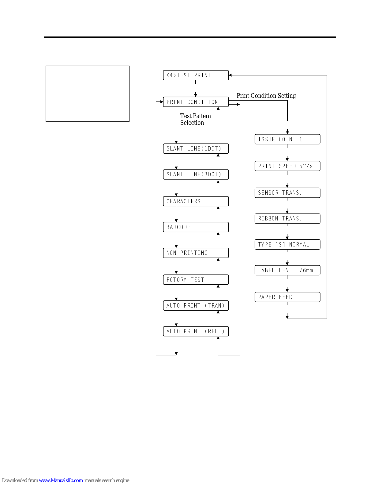
APPENDIX 4 SYSTEM MODE
EO1-33032
A4.6 Test Print
A4-14
A4.6 Test Print
The Test Print menu contains the following:
Outline of Test Print
I
n the Test Print mode, you can
p
rint test patterns after setting
up some conditions. This is
useful for checking the printers
operation or for testing the
quality of new ribbon or media.
[RESTART] [FEED]
[RESTART]
[FEED]
[RESTART]
[FEED]
[RESTART]
[FEED]
[RESTART]
[FEED]
[RESTART]
[FEED]
[RESTART]
[FEED]
[RESTART]
[FEED]
[RESTART]
[FEED]
[PAUSE]
[PAUSE]
[PAUSE]
[PAUSE]
[PAUSE]
[PAUSE]
[PAUSE]
[PAUSE]
[PAUSE]
,668( &2817
35,17 63((' ´V
6(1625 75$16
5,%%21 75$16
7<3( >6@ 1250$/
/$%(/ /(1 PP
3$3(5 )(('
!7(67 35,17
35,17 &21',7,21
6/$17 /,1('27
6/$17 /,1('27
&+$5$&7(56
%$5&2'(
12135,17,1*
)&725< 7(67
$872 35,17 75$1
$872 35,17 5()/
Test Pattern
Selection
Print Condition Setting

APPENDIX 4 SYSTEM MODE
EO1-33032
A4.6 Test Print
A4-15
A4.6 Test Print (Cont.)
While in a Pause condition press and hold the
[RESTART]
key until
“<0>RESET” appears in the display.
Then, press the
[FEED]
key four times, and “<4>TEST PRINT” message
appears.
Specifying the Print Condition for the Test Print
The print conditions for Test Printing should be specified before printing.
When “<4>TEST PRINT” appears, press the
[PAUSE]
key.
Issue Count Setting
To enter the Issue Count Setting menu, press the
[PAUSE]
key.
After selecting the issue count, press the
[PAUSE]
key to go to Print
Speed Setting.
35,17 &21',7,21
[RESTART]
[FEED]
,668( &2817
,668( &2817
,668( &2817
,668( &2817
,668( &2817
,668( &2817
,668( &2817
,668( &2817
,668( &2817
,668( &2817
!7(67 35,17
!5(6(7

APPENDIX 4 SYSTEM MODE
EO1-33032
A4.6 Test Print
A4-16
A4.6 Test Print (Cont.)
Print Speed Setting
Select the print speed for the test print.
After selecting the print speed, press the
[PAUSE]
key to go to Sensor
Type Selection.
Sensor Type Selection
Select the sensor type among “TRANS” (Feed Gap Sensor), “REFLECT”
(Black Mark Sensor) and “NONE”.
After selecting the sensor type, press the
[PAUSE]
key to go to Ribbon
Type Selection.
Ribbon Type Selection
Select the ribbon type for the test print from “NO RIBBON”, “RIBBON
TRANS.”, and “NO TRANS.”.
After selecting the printing mode, press the
[PAUSE]
key to go to Issue
Mode Selection.
35,17 63((' ´V
35,17 63((' ´V
35,17 63((' ´V
[RESTART]
[FEED]
6(1625 121(
6(1625 5()/(&7
[RESTART]
[FEED]
6(1625 75$16
5,%%21 12 5,%%21
5,%%21 75$16
[RESTART]
[FEED]
5,%%21 75$16
No ribbon
Transmissive ribbon
None
Black Mark Sensor
6(1625 75$16
Feed Gap Sensor
NOTE:
Select the sensor type which
matches the media being used.
B
asically, the Reflective Sensor
(Black Mark Sensor) is for tag
p
aper, and the Transmissive
Sensor (Feed Gap Sensor) is
f
or labels.
NOTE:
Select the ribbon type which
matches the media and ribbon
being used.
B
asically, the Transmissive and
N
on Transmissive are for the
use with ribbon, and No Ribbon
is for use with Direct Thermal
p
aper.
35,17 63((' ´V
35,17 63((' ´V
5,%%21 12 75$16
Non transmissive ribbon

APPENDIX 4 SYSTEM MODE
EO1-33032
A4.6 Test Print
A4-17
A4.6 Test Print (Cont.)
Issue Mode Selection
Select the issue mode for the test print by selecting between “[S]
NORMAL” (Batch mode) and “[H] PEEL OFF” (Strip mode).
After selecting the Issue Mode, press the
[PAUSE]
key to go t o Label
Length Setting.
Label Length Setting
Select the label length for the test print in a range from 5 mm to 999 mm.
[FEED]
key: Pressing the
[FEED]
key once causes a –1 mm
change, down to 5 mm.
[RESTART]
key: Pressing the
[RESTART]
key once causes a +1 mm
change, up to 999 mm.
After selecting the label length, press the
[PAUSE]
key to go t o Paper
Feed Selection.
Paper Feed Selection
Select whether or not a paper feed is performed.
After selecting the paper feed, press the
[PAUSE]
key. If "PAPER
FEED" was selected the printer will feed the media. The display returns
to the “<4>TEST PRINT”.
7<3(>6@1250$/
7<3(>+@3((/ 2))
7<3(>6@1250$/
[RESTART]
[FEED]
Batch mode
Strip mode
[RESTART]
[FEED]
/$%(/ /(1 PP
/$%(/ /(1 PP
/$%(/ /(1 PP
3$3(5 )(('
3$3(5 12 )(('
3$3(5 )(('
[RESTART]
[FEED]
Paper feed is
available.
Paper feed is no
t
available
.
NOTE:
Press and hold the
[RESTART]
or
[FEED]
key to advance the
values quickly and continuously.
To stop, release the key.
NOTE:
When “PAPER FEED” is
selected, the printer feeds the
media to the correct print start
p
osition for the selected
conditions.
When “PAPER NO FEED” is
selected, the printer makes no
p
re-feed to set the print start
p
osition. If the print start
p
osition adjustment is
unnecessary, Select "PAPER
N
O FEED" and save media.

APPENDIX 4 SYSTEM MODE
EO1-33032
A4.6 Test Print
A4-18
A4.6 Test Print (Cont.)
Test Print Pattern Selection
With “<4>TEST PRINT” displayed after paper feed selection, press the
[PAUSE]
key.
Select a test print pattern from the following options.
Slant Line (1 dot)
While displaying Slant Line (1 dot), press the
[PAUSE]
key to start
printing the slant line patterns (1 dot). After printing is completed, the
display returns to “<4>TEST PRINT”.
Pressing the
[PAUSE]
key causes the display to show “SLANT LINE
(1DOT)” again. Then, press the
[FEED]
key.
Slant Line (3 dots)
While displaying the Slant Line (3 dots), press the
[PAUSE]
key to start
printing the slant line patterns (3 dots). After printing is completed, the
display returns to “<4>TEST PRINT”.
Pressing the
[PAUSE]
key causes the display to show “SLANT LINE
(3DOT)” again. Then, press the
[FEED]
key.
35,17 &21',7,21
6/$17 /,1('27
35,17 &21',7,21
[RESTART]
[FEED]
$872 35,175()/
6/$17 /,1('27
6/$17 /,1('27
&+$5$&7(56
%$5&2'(
12135,17,1*
)$&725< 7(67
$872 35,1775$1
6/$17 /,1('27
NOTE:
See A4.8.3 for further
information.
Print Sample of Slant Line
(
1 dot)
Print Sample of Slant Line
(3 dots)

APPENDIX 4 SYSTEM MODE
EO1-33032
A4.6 Test Print
A4-19
A4.6 Test Print (Cont.)
Characters
While displaying the Characters, press the
[PAUSE]
key to start printing
the characters. After printing is completed, the display returns to
“<4>TEST PRINT”.
Pressing the
[PAUSE]
key causes the display to show “CHARACTERS”
again. Then, press the
[FEED]
key.
Barcode
While displaying the Barcode, press the
[PAUSE]
key to start printing
the bar codes. After printing is completed, the display returns to
“<4>TEST PRINT”.
Pressing the
[PAUSE]
key causes the display to show “BARCODE”
again. Then, press the
[FEED]
key.
Non-Printing
While displaying the Non-printing, press the
[PAUSE]
key to start
issuing a blank page of media. After printing is completed, the display
returns to “<4>TEST PRINT”.
Pressing the
[PAUSE]
key causes the display to show “NON-
PRINTING” again. Then, press the
[FEED]
key.
Factory Test
While displaying the Factory test, press the
[PAUSE]
key to start
printing the factory test pattern. After printing is completed, the display
returns to “<4>TEST PRINT”.
Pressing the
[PAUSE]
key causes the display to indicate “FACTORY
TEST” again. Then, press the
[FEED]
key.
&+$5$&7(56
%$5&2'(
12135,17,1*
NOTE:
The Non-Printing function
looks like a media feed.
NOTES:
• Factory test print conditions:
One paper feed, Slant lines (3
dots), Bar codes, Characters,
Item count: 5 pcs. each, Print
speed: 5”/sec., Sensor type:
Black or Feed gap sensor
Ribbon type: Transparent
• When the feed gap sensor is
selected, a gap length is 3
mm.
Print method: Thermal
transfer, Issue mode: Batch
printing, Label length: 76
mm, Print tone fine
adjustment.
)$&725< 7(67
Print Sample of Characters
Print Sample of Barcodes
Print Sample of Non-print

APPENDIX 4 SYSTEM MODE
EO1-33032
A4.7 Dump Mode
A4-20
A4.6 Test Print (Cont.)
A4.7 Dump Mode
Auto Print
While displaying Auto Print, press the
[PAUSE]
key to feed one piece of
media and print slant lines (3 dots) on 5 pieces of media.
Next, press the
[PAUSE]
key to print bar codes on 5 pieces of media.
Pressing the
[PAUSE]
key again causes the printer to print characters on
5 pieces of media.
In Dump mode, any characters sent from the host computer will be
printed. Received characters are expressed in hexadecimal values. This
allows the user to verify programming commands and debug their
program.
And for other details, please refer to your nearest TOSHIBA TEC service
representative.
NOTE:
Select “AUTO PRINT (TRAN)”
when using labels, and “AUTO
PRINT (REFL)” when using tag
p
aper.
$872 35,1775$1
$872 35,175()/
Feed Gap Sensor
Black Mark Sensor

APPENDIX 4 SYSTEM MODE
EO1-33032
A4.8 Additional Information
A4-21
A4.8 Additional Information
A4.8.1 Self-Diagnostic Test Result Sample and Descriptions
• Print Sample
• Descriptions
(1) Program ROM Check (Model Name, Date, Version, Part number, Checksum)
PROGRAM
B-492 20SEP2001
V1.0
A FMRM0067001: 1A00
(2) Boot Check (Model Name, Date, Version, Part Number, Checksum)
BOOT B-492 01SEP2001
V1.0
A FMRM0066901: 8500
PROGRAM B-492 20SEP2001
V1.0A FMRM0067001: 1A00
BOOT B-492 01SEP2001
V1.0 FMRM0066901:8500
FONT 5600
EEPROM OK
SDRAM 8MB
CARD SLOT1 ATA
SLOT2 LAN
SENSOR [H]20°C [A]22°C [S]25°C
[R]4.2V [T]2.5V
[RANK]7
DIP SW 1: ON 2: OFF 3: OFF
EXP.I/O NG
KEY BRD NG
N
OTES:
1. Print conditions:
Preset count: 1, Print speed: 5”/sec., Sensor: No sensor, Printing method: Thermal transfer,
Supply length: 59 mm, Issue mode: Batch printing
2. Software version No., Part No. of ROM and checksum
will vary
with the software version of PROGRAM
ROM.
3. The last two digits of the checksum are usually “00”.
4. The symbol”°” of ‘°C” may not be printed depending on the type of character code selected.
(1)
(2)
(3)
(4)
(5)
(6)
(7)
(8)
(9)
(10)
Checksum
Part No. of ROM or software
Revision No.: Space or A to Z
Program area
Model name
Software version No.
Checksum of Boot area
Part No. of ROM or software
Revision No.: Space or A to Z
Boot are
a
Model name
Software version No.

APPENDIX 4 SYSTEM MODE
EO1-33032
A4.8 Additional Information
A4-22
A4.8.1 Self-Diagnostic Test Result Sample and Descriptions (Cont.)
(3) Alphanumeric Font ROM Check
FONT 5600
(4) EEPROM Check
EEPROM
OK
(5) SDRAM Capacity
SDRAM
8MB
(6) PC Card Slot Check
CARD
SLOT 1 ATA
SLOT 2
LAN
(7) Sensor Check
The status of the Print Head Thermistor, Environmental Temperature Thermistor, Heat Sink Thermistor,
Black Mark Sensor, Feed Gap Sensor, and Print Head Resistance Rank are printed on this line.
SENSOR [H]20°C
[A]22°C [S]25°C [R]4.2V [T]2.5V [RANK]7
Checksum of Font area
Font area
OK: Data in the check area can be properly read/written.
NG: Data in the check area cannot be properly read/written.
EEPROM (Backup Memory)
Capacity of DRAM
System/Drawing memory
ATA: ATA Card is inserted.
LAN: LAN card is inserted.
FSH: Flash memory card is inserted.
NO: Unformatted ATA card/Flash memor
y
card or no card is inserted.
Slot
PCMCIA Card
Feed gap sensor status:
0.0 – 5.0V
Heat sink thermistor status:
25°C, 80°C, 90°C
Print Head Resistance Rank
0 – 7
(See Table on the following
pag
e.)
Black mark sensor status:
0.0 – 5.0V
Print head thermistor status:
0°C - 86°C
Environmental thermistor status:
0 - 86°C
If it is undetectable, “--°C “ is printed.

APPENDIX 4 SYSTEM MODE
EO1-33032
A4.8 Additional Information
A4-23
A4.8.1 Self-Diagnostic Test Result Sample and Descriptions (Cont.)
Print Head Resistance Rank Table
Rank Average resistance (ohm) Rank Average resistance (ohm)
0 1409 to 1454 4 1219 to 1265
1 1361 to 1408 5 1171 to 1218
2 1314 to 1360 6 1124 to 1170
3 1266 to 1313 7 1076 to 1123
(8) DIP Switch Status
DIP SW 1: ON
2: OFF 3: OFF
(9) Expansion I/O Interface Check
EXP.I/O
OK
(10) DIN Connector for the Keyboard (KB-80) Check
KEY BRD
OK
Loopback test
OK: The circuit has no problem.
NG: The circuit has a problem or loopback jig is not attached.
Expansion I/O PC board
OK: The connector has no problem.
NG: The connector has a problem or loopback jig is not attached.
DIN Connector for the KB-80 keyboard
Connector: FCN-781P024-G/P
• • • • • • • • • •
•
• •
300Ω×5
300Ω
Vcc
GND
1 2 3 4 5 7 8 9 10 11
12 15 21
DIN Connector: TCS7588-01-201
Pin 3 and Pin 4 are short-circuited.
Pin 5 and Pin 6 are short-circuited.
1
2
3
4
5
6
7
8

APPENDIX 4 SYSTEM MODE
EO1-33032
A4.8 Additional Information
A4-24
A4.8.2 Maintenance Counter and Parameter Check Print Sample and Descriptions
• Print Sample
TOTAL FEED 1.1Km
FEED 1.1Km
PRINT 0.5Km
HEAD U/D 32
RIBBON 3h
SOLENOID 0h
232C ERR 255
SYSTEM ERR 0
POWER FAIL 0
[PC] [KEY]
FEED +2.0mm FEED +0.0mm
PEEL OFF +0.0mm PEEL OFF +1.0mm
BACK +0.0mm BACK +0.0mm
TONE(T) +0 step TONE(T) +0 step
TONE (D) +0 step TONE(D) +0 step
RBN(FW) -10 RBN (FW) -8
RBN (BK) +0 RBN (BK) +0
PO SPEED +0 PO SPEED +0
X ADJ. +0.0mm
THRESHOLD (R) 1.0V
THRESHOLD (T) 1.4V
FONT [PC-850] [0]
CODE [AUTO]
RIBBON [TRANS]
SPEED [9600]
DATA LENG. [8]
PARITY [EVEN]
CONTROL [XON+READY AUTO]
MESSAGE [ENGLISH]
RIBBON SAVE [ON]
FEED KEY [FEED]
EURO CODE [B0]
AUTO HD CHK [OFF]
ACK/BUSY [TYPE1]
WEB PRINTER [OFF]
KB80 CONNECT [OFF]
RIBBON NEAR END [30m]
PRTR IP ADDRESS [192.168.010.020]
GATE IP ADDRESS [000.000.000.000]
SUBNET MASK [255.255.255.000]
TTF AREA [704kB]
EXT CHR AREA [128kB]
PC SAVE AREA [64kbB
SOCKET PORT [OFF] [08000]
(1)
(2)
(3)
(4)
(5)
(6)
(7)
(8)
(9)
(10)
(11)
(12)
(13)
(14)
(15)
(16)
(17)
(18)
(19)
(20)
(21)
(22)
(23)
(24)
(25)
(26)
(27)
(28)
(29)
(30)
(31)
(32)
(33)
(34)
(35)
(36)
(37)
(38)
(39)
(40)
(41)
(42)
(43)
N
OTE:
Print conditions:
Preset count: 1, Print speed: 5”/sec., Sensor: No sensor, Printing mode: Thermal transfer,
Media length: 170 mm, Issue mode: Batch printing

APPENDIX 4 SYSTEM MODE
EO1-33032
A4.8 Additional Information
A4-25
A4.8.2 Maintenance Counter and Parameter Check Print Sample and Descriptions
(Cont.)
•
Descriptions of the Maintenance Counter
No. Item Count Condition Range
(1) Total media distance covered 0.0 to 2000.0 km
(2) Media distance covered
Counted when the feed motor is driven to feed,
print and issue the media. (Also counted
during back feed.) See NOTE 6.
0.0 to 181.9 km
(3) Print distance
Counted while printing. (Back feeding is not
counted.) See NOTE 2.
0.0 to 200.0 km
(4) Head up/down count
Counts every print head up and down
movement using the ribbon saving solenoid.
(Up + down=1 count) See NOTE 3.
0 to 2000000 times
(5) Ribbon motor operating time
Counts when the ribbon motor is driven to feed,
print and issue media. (The driving time is also
counted during back feed.) See NOTE 4.
0 to 2000 hours
(6)
Head up solenoid operating
time
Counted during the ribbon saving.
See NOTE 4.
0 to 1000 times
(7) RS-232C hardware error count
Counted when a parity, overrun or framing
error occurs. See NOTE 5.
0 to 255 times
(8) System error count Counted when any error occurs. 0 to 15 times
(9) Momentary power failure count
Counts the number of times the power restores
while the CPU is busy after reset.
0 to 15 times
•
Descriptions of the Parameters
No. Item Contents
(10) Feed length fine adjustment (PC), (KEY) -50.0 mm to +50.0 mm
(11) Strip position fine adjustment (PC), (KEY) -50.0 mm to +50.0 mm
(12) Back feed length fine adjustment (PC), (KEY) -9.9 mm to +9.9 mm
(13)
Print tone fine adjustment (Thermal transfer), (PC),
(KEY)
-10 step to +10 step
(14)
Print tone fine adjustment (Thermal direct), (PC),
(KEY)
-10 step to +10 step
(15)
Ribbon rewind motor driving voltage fine adjustment
(PC), (KEY)
-15 step to +0 step
(16)
Ribbon feed motor driving voltage fine adjustment
(PC), (KEY)
-15 step to +0 step
(17) Strip Motor driving speed fine adjustment (PC), (KEY) +0 to +4
(18) X axis fine adjustment -99.5 mm to +99.5 mm
N
OTES:
1. The item from (2) through (9) are initialized to “0” after RAM clear.
2. If the Print distance is 5.5m or less, it is rounded down and no data is added to the memory at power off.
3. If the count is 31 counts or less, it is rounded down and no data is added to the memory at power off.
4. If the driving time is 27 sec. or less, it is rounded down and no data is added to the memory at power off.
5. When more than 1 byte-data is continuously sent, they are counted by byte.
6. If the media distance covered is 69.4 cm or less, it is rounded down and no data is added to the memory at
power off.
APPENDIX 4 SYSTEM MODE
EO1-33032
A4.8 Additional Information
A4-26
A4.8.2 Maintenance Counter/Parameter Check Print Sample and Descriptions (Cont.)
No. Item Contents
(19)
Threshold manual fine adjustment for the black mark
sensor
0.0V to 4.0V
(20)
Threshold manual fine adjustment for the feed gap
sensor
0.0V to 4.0V
Character
PC-850 PC-851 PC-1252 LATIN9
PC-852 PC-855 PC-1253 Arabic
PC-857 PC-1250 PC-1254
PC-8 PC-1251 PC-1257
(21)
Font zero
0: No slash used.
: Slash used.
(22) Control code
AUTO: Automatic selection
ESC LF NUL: ESC LF NUL mode
{|}: Mainframe mode
1B 1C 1D: Manual
(23) Ribbon type
NO RIBBON: No ribbon
TRANS: Transparent ribbon end
NON TRANS: Opaque ribbon end
(24) Baud rate
2400: 2400 bps
9600: 9600 bps
4800: 4800 bps
19200: 19200 bps
38400: 38400 bps
(25) Data length
7: 7 bits
8: 8 bits
(26) Parity
NON: None
ODD: ODD
EVEN: EVEN
(27) Transmission control code
XON/XOFF: XON/XOFF
READY/BUSY: READY/BUSY
(DTR)
XON+READY AUTO:
XON/XOFF+READY/BUSY (DTR)
XON/XOFF AUTO: XON/XOFF
READY/BUSY RTS: RTS
(28) Language selection for LCD message
ENGLISH: English
GERMAN: German
FRENCH: French
DUTCH: Dutch
SPANISH: Spanish
JAPANESE: Japanese
ITALIAN: Italian
(29) Ribbon saving function
ON: Use
OFF: Non use
(30) Feed key function
FEED: Feeds one label
PRINT: Prints image buffer on one
label
(31) Euro font code 20H to FFH
(32) Auto print head broken element check
ON: Available
OFF: Unavailable

APPENDIX 4 SYSTEM MODE
EO1-33032
A4.8 Additional Information
A4-27
A4.8.2 Maintenance Counter/Parameter Check Print Sample and Descriptions (Cont.)
No. Item Contents
(33) Centronics ACK/BUSY timing setting
TYPE1: ACK is output when
canceling BUSY.
TYPE2: ACK is output after canceling
BUSY.
(34) Web printer function
ON: Available
OFF: Unavailable
(35) KB-80 keyboard connection
ON: Connect
OFF: Not connect
(36) Ribbon near end detection
30m: Warning when the remaining
ribbon length is about 30 m.
70m: Warning when the remaining
ribbon length is about 70 m.
(37) Printer IP address ***.***.***.***
(38) Gateway IP address ***.***.***.***
(39) Subnet mask ***.***.***.***
(40) True type font registration area size 0 KB to 896 KB (unit of 64 KB)
(41) External character registration area size 0 KB to 896 KB (units of 64 KB)
(42) PC saving area size 0 KB to 896 KB (units of 64 KB)
(43) Socket communication setting and port number
ON: Communicable
OFF: Not communicable
Port No.: 0 -065535
A4.8.3 Magnified Views of Slant Line Pattern
•
1-dot Slant Line (Black Area Ratio: 16.7%)
•
3-Dot Slant Line (Black Area Ratio: 16.7%)

APPENDIX 5 PRINT SAMPLES
EO1-33032
APPENDIX 5 PRINT SAMPLES
A5- 1
APPENDIX 5 PRINT SAMPLES
Font

APPENDIX 5 PRINT SAMPLES
EO1-33032
APPENDIX 5 PRINT SAMPLES
A5- 2
APPENDIX 5 PRINT SAMPLES (Cont.)
Bar codes
0: JAN8, EAN8 1: MSI
2: Interleaved 2 of 5 3: CODE39 (Standard)
4: NW7 5: JAN13, EAN13
6: UPC-E 7: EAN13+2 digits
8: EAN13+5 digits A:CODE128
B: CODE39 (Full ASCII) C: CODE93
G: UPC-E+2 digits H: UPC-E+5 digits
I: EAN8+2 digits J: EAN8+5 digits

APPENDIX 5 PRINT SAMPLES
EO1-33032
APPENDIX 5 PRINT SAMPLES
A5- 3
APPENDIX 5 PRINT SAMPLES (Cont.)
K: UPC-A L: UPC-A+2 digits
M: UPC-A+5 digits N: UCC/EAN128
O: Industrial 2 of 5 P: PDF417
Q: Data Matrix R: Customer bar code
S: Customer bar code of high priority T: QR code
U: POSTNET V: RM4SCC
W: KIX Code X: Micro PDF417
Z: MaxiCode

GLOSSARIES EO1-33032
GLOSSARIES
GLOSSARIES
Bar code
A code which represents alphanumeric characters
by using a series of black and white stripes in
different widths. Bar codes are used in various
industrial fields: Manufacturing, Hospitals,
Libraries, Retail, Transportation, Warehousing, etc.
Reading bar codes is a fast and accurate means of
capturing data while keyboard entry tends to be
slow and inaccurate.
Batch mode
Issue mode that continuously prints media until the
required number has been printed.
Black mark
A mark printed on the media enabling the printer to
detect the correct start position of the media,
helping to maintain constant print position.
Black mark sensor
A reflective sensor that detects the difference
between a black mark and the print area to find the
print start position.
DPI
Dots Per Inch
A unit used to express print density or resolution.
Expansion I/O interface
This interface allows the printer to be connected to
an external device such as a applicator and to
receive feed, print start, and pause signals from
that device and to send back print, pause, and error
status signals to the external device.
Feed gap sensor
A transmissive sensor that detects the difference
between the gap between labels and the label itself,
to find the print start position of the label.
Font
A complete set of alphanumeric characters in one
style of type. E.g. Helvetica, Courier, Times
Gap
Distance from the bottom of one label to the top of
the next
IPS
Inchs per second
A unit used to express print speed.
KB-80 keyboard interface
This interface allows the B-492L/R printer to
connect to the optional KB-80 keyboard providing
it with a standalone capability. Label programs
may be stored in the KB-80 flash memory and
labels can be printed using data input through the
keyboard instead of from a host computer.
LCD
Liquid Crystal Display
Installed on the operation panel and displays
operation modes, error messages and so on.
Label
A type of media with adhesive backing supplied on
a backing paper.
Media
Material on which images are printed by the
printer. Label, tag paper, fanfold paper, perforated
paper, etc.
PCMCIA interface
An optional interface board that may be installed in
the B-492L/R printer to allow the use of the small
credit card sized PC cards such as flash memory
cards and LAN cards. PCMCIA is the acronym for
Personal Computer Memory Card International
Association.
Printer driver
A software program that will convert the
application program’s printing request into the
language that the printer understands.
Print head element
The thermal print head consists of a single line of
tiny resistive elements which when current is
allowed to flow through them it heats up causing a
small dot to be burned onto thermal paper or a
small dot of ink to be transferred from a thermal
ribbon to ordinary paper.

GLOSSARIES EO1-33032
GLOSSARIES
Pre-printed label
A type of label on which characters, logos, and
other designs have been already printed.
Printing speed
The speed at which printing occurs. This speed is
expressed in units of IPS (inches per second).
Reflective sensor
See Black mark sensor.
Resolution
The degree of detail to which an image can be
duplicated. The minimum unit of divided image is
called a pixel. As the resolution becomes higher,
the number of pixels increases, resulting in a more
detailed image.
Ribbon
An inked film used to transfer an image onto the
media. In thermal transfer printing, it is heated by
the thermal print head, causing an image to be
transferred onto the media
Supply
Media and ribbon
Thermal direct printing
A printing method using no ribbon, but thermal
media which reacts to heat. The thermal print head
heats the thermal media directly, causing print
image to be printed on the media.
Thermal print head
A print head using thermal transfer or thermal
direct printing method..
Thermal transfer printing
A printing method that uses the thermal print head
to heat an ink or resin coating on the ribbon against
the media, causing the ink/resin to transfer onto the
media.
Threshold setting
A sensor setting operation to help the printer
maintain a constant print position on pre-printed
media. .
Transmissive sensor
See Feed gap sensor.
X Axis
In the printer, it is the horizontal position (left and
right) of the print on the label. This position may
be adjusted by command from the host computer,
or by a parameter change on the printer.

INDEX EO1-33032
INDEX
INDEX
B
Backing paper 2-9, A1-3
Bar code A1-1, A4-19, A5-2
Batch mode 2-9
Black mark 2-8, A1-2
Black mark length A1-3
Black mark sensor 2-8, A4-13
C
Centronics 1-3, 2-2, 2-3, A1-1
D
Dimensions 1-2, 1-5, A1-1
DC Power Connector 1-3, 1-5
DC Power Cable 2-4
E
Effective print range A1-4
ERROR LED 1-4, 3-1
Error message 5-1
Expansion I/O interface 1-3, 2-3, A1-1
F
Fan filter 2-2
Feed gap sensor 2-8, A4-13
FEED key 1-4, 3-1
Flash memory card 2-13, A1-2
G
Gap between labels 2-8, A1-3
Gap length A1-3
Guaranteed print area A1-4
H
Head lever 1-4, 2-6
I
Interface A1-1
Issue mode 2-9, A4-17
J
Jammed media 5-1, 5-3
K
KB-80-QM keyboard 1-1, 2-3
Keyboard interface 1-3, 2-3, A1-1
Keyboard module A1-2
L
Label A1-2
Label length A1-3
Label pitch A1-3
Label width A1-3
LCD message display 1-4, 3-1, A1-1
M
Maintenance counter A4-24
Media 4-5, A1-2
Media guide plate 4-2
O
ONLINE LED 1-4, 3-1
Operation Panel 1-3, 1-4, 3-1
P
Parallel interface 1-3, 2-3, A1-1
Parallel port 2-3
PAUSE key 1-4, 3-1
PCMCIA card 2-12
PCMCIA interface board 2-12, A1-2
Platen 4-1
Power consumption A1-1
Power cord 1-1, 2-4
POWER LED 1-4, 3-1
Power supply unit 1-5
Power switch 2-4, 2-5
Pre-printed label 5-3
Printer driver 6-1
Printer parameter A4-2, A4-6
Print head 1-3, 4-1
Print head element 4-1, A4-5
Printing method A1-1
Printing speed A1-1

INDEX EO1-33032
INDEX
R
Reflective sensor A1-4
Resolution A1-1
RESTART key 1-4, 3-1
Ribbon 2-11, 4-5, A1-5
Ribbon width A1-5
Rotation A1-1
RS-232C 1-3, 2-2, 2-3, A1-1, A3-1
S
Self diagnostic test A4-2, A4-3, A4-21
Sensor 2-8, 5-1
Serial interface 1-3, 2-3, A1-1, A3-1
Supply voltage A1-1
T
Test print 2-13, A4-14
Thermal direct A1-1
Thermal transfer A1-1
Threshold setting 5-3
Transmissive sensor A1-3
Two dimensional code A1-1
W
Weight A1-1


E
PRINTED IN JAPAN
EO1-33032
 Loading...