


RemotEye 4
User Manual
Document Number: 90988-007
September 2018

2 RemotEye 4 User Manual – 90988-007
ABOUT THIS MANUAL
This manual was written by the TOSHIBA Engineering and Marketing Groups. These groups are tasked with
providing technical documentation for the RemotEye 4 system. Every effort has been made to provide accurate and
concise information to you, our customer.
This manual provides information on how to safely install, operate, and maintain your RemotEye 4 system. This
manual includes a section of general safety instructions that describes the warning labels and symbols that are used
throughout the manual. Read the manual completely before installing, operating, or performing maintenance on this
equipment.
The information in this manual is subject to change without notice.
The Toshiba International Corporation shall not be liable for direct, indirect, special, or consequential damages
resulting from the use of the information contained within this manual.
This manual is copyrighted. No part of this manual may be photocopied or reproduced in any form without the prior
written consent of the Toshiba International Corporation.
TOSHIBA is a registered trademark of the TOSHIBA Corporation.
RemotEye is a registered trademark of the Toshiba International Corporation.
All other product or trade references appearing in this manual are registered trademarks of their respective owners.
© Copyright 2018 Toshiba International Corporation.
All rights reserved.

RemotEye 4 User Manual – 90988-007 3
CONTACTING TOSHIBA’S CUSTOMER SUPPORT CENTER
TOSHIBA’s Customer Support Center can be contacted to obtain help in resolving any RemotEye 4 system problem
that you may experience or to provide application information.
The Support Center can be reached at 855-803-7087 (toll free) or 713-466-0277. The center is open from 8 a.m. to 5
p.m. (CST), Monday through Friday.
Email us at: ToshibaUPS@toshiba.com
You may also contact TOSHIBA by writing to:
TOSHIBA International Corporation - UPS
13131 West Little York Road
Houston, Texas 77041-9990
For further information on TOSHIBA’s products and services, please visit our website at:
HTTP://WWW.TOSHIBA.COM/IND.
IMPORTANT NOTICE
This user manual may not cover all of the variations in equipment, nor may it provide information on every possible
contingency concerning installation, operation, or maintenance.
The contents of this manual shall not become a part of or modify any prior agreement, commitment, or relationship
between the customer and the TOSHIBA International Corporation's UPS Division. The sales contract contains the
entire obligation of the TOSHIBA International Corporation's UPS Division. The warranty contained in the contract
between the parties is the sole warranty of the TOSHIBA International Corporation's UPS Division, and any
statements contained herein do not create new warranties or modify the existing warranty.
Any electrical or mechanical modifications to this equipment without prior written consent of the TOSHIBA
International Corporation will void all warranties and may void the UL/CUL listing or other safety certifications.
Unauthorized modifications may also result in equipment damage or personal injury.
When used on UPS supporting safety critical equipment, carefully analyze the impact of allowing remote access of
the UPS control features.
IMPORTANT SAFETY INSTRUCTIONS
This manual contains important instructions that should be followed during the installation, maintenance, and
operation of the UPS and its batteries to assure safe and proper operation.
Turn off, lockout, and tagout all power sources before connecting the power wiring to the equipment or when
performing maintenance.
Unauthorized personnel should not service batteries.
Contact your nearest Toshiba authorized service center for battery replacement.
Qualified Personnel shall:
Have read the entire operation manual of the system being serviced.
Be trained and authorized to safely energize, de-energize, ground, lockout and tag circuits and equipment,
and clear faults in accordance with established safety practices.
Be trained in the proper care and use of protective equipment such as safety shoes, rubber gloves, hard hats,
safety glasses, face shields, flash clothing, etc., in accordance with established safety practices.
Be trained in rendering first aid.
Be knowledgeable of batteries and the required handling and maintenance precautions.

4 RemotEye 4 User Manual – 90988-007
This Page Intentionally Left Blank

RemotEye 4 User Manual – 90988-007 5
TABLE OF CONTENTS
ABOUT THIS MANUAL ........................................................................................................................... 2
CONTACTING TOSHIBA’S CUSTOMER SUPPORT CENTER ....................................................... 3
IMPORTANT NOTICE ............................................................................................................................. 3
IMPORTANT SAFETY INSTRUCTIONS .............................................................................................. 3
TABLE OF CONTENTS ........................................................................................................................... 5
LIST OF FIGURES .................................................................................................................................... 9
LIST OF TABLES .................................................................................................................................... 11
1 GENERAL SAFETY INSTRUCTIONS ....................................................................................... 13
SAFETY ALERT SYMBOLS ................................................................................................................... 13
SPECIAL SYMBOLS ................................................................................................................................ 13
1.2.1 Electrical Hazard Symbol .................................................................................................................... 13
1.2.2 Explosion Hazard Symbol ................................................................................................................... 14
EQUIPMENT WARNING LABELS ......................................................................................................... 14
INSTALLATION PRECAUTIONS ........................................................................................................... 14
2 INTRODUCTION ........................................................................................................................... 15
PURPOSE & MANUAL OVERVIEW ...................................................................................................... 15
APPLICABLE SPECIFICATIONS ........................................................................................................... 15
UPS COMPATIBILITY ............................................................................................................................. 16
PACKAGE CONTENTS ........................................................................................................................... 16
REMOTEYE 4 LAYOUT AND LED INDICATORS ............................................................................... 17
2.5.1 Hard Reset Button ................................................................................................................................ 18
FEATURES ................................................................................................................................................ 20
2.6.1 HTTP Web Access ............................................................................................................................... 20
2.6.2 SNMP Access ...................................................................................................................................... 20
2.6.3 BACnet and Modbus Access ............................................................................................................... 21
2.6.4 Additional Features .............................................................................................................................. 21
2.6.5 RemotEye 4 Support Software Programs ............................................................................................ 22
2.6.6 Optional – Environmental Monitoring Device (EMD) ........................................................................ 22
2.6.7 Optional – RemotEye Sensor Pack for EMD ....................................................................................... 23
2.6.8 Optional – RemotRadar Software ........................................................................................................ 23
3 SETUP .............................................................................................................................................. 24
CHECKLIST .............................................................................................................................................. 24
INSTALL REMOTEYE 4 IN UPS ............................................................................................................ 25
4 REMOTEYE 4 NETWORK CONNECTION SETUP ................................................................ 31
IP ADDRESS SETUP WITH DHCP ......................................................................................................... 31
IP ADDRESS SETUP WITH CUSTOM NETWORK SETTINGS ........................................................... 32
4.2.1 Install USB Driver (Windows 8.1) ...................................................................................................... 32
4.2.2 Install USB Driver (Windows 7) ......................................................................................................... 33
4.2.3 Establishing Comminication ................................................................................................................ 33
4.2.4 Set the IP Address ................................................................................................................................ 34
5 SYSTEM CONFIGURATION VIA WEB INTERFACE ........................................................... 36
SOFTWARE SETUP ................................................................................................................................. 36
5.1.1 First Time Setup ................................................................................................................................... 36
DASHBOARD (HOME PAGE) LAYOUT ............................................................................................... 39
5.2.1 Customizing the Dashboard Layout ..................................................................................................... 42

6 RemotEye 4 User Manual – 90988-007
WEB NAVIGATION ................................................................................................................................. 44
5.3.1 UPS MONITORING Drop-down Menu .............................................................................................. 45
5.3.2 UPS MANAGEMENT Drop-down Menu ........................................................................................... 46
5.3.3 SETTTINGS Drop-down Menu ........................................................................................................... 46
5.3.4 EMD Drop-down Menu ....................................................................................................................... 46
5.3.5 {Username} Drop-down Menu ............................................................................................................ 46
6 PROTOCOL SETUP ...................................................................................................................... 47
SNMP SETUP ............................................................................................................................................ 47
6.1.1 Toshiba MIB Files ............................................................................................................................... 48
6.1.2 NMS (Manager) Settings ..................................................................................................................... 48
MODBUS TCP/IP OR BACNET IP SETUP ............................................................................................. 48
6.2.1 Configure for Modbus TCP/IP ............................................................................................................. 48
6.2.2 Configure for BACnet IP ..................................................................................................................... 49
MODBUS RTU OR BACNET MS/TP SETUP ......................................................................................... 50
6.3.1 Configure for Modbus RTU ................................................................................................................. 50
6.3.2 Configure for BACnet MS/TP ............................................................................................................. 52
7 OPTIONAL FEATURES SETUP ................................................................................................. 55
RADIUS CONFIGURATION ................................................................................................................... 55
EMAIL NOTIFICATION .......................................................................................................................... 55
REMINDERS ............................................................................................................................................. 57
WIRELESS SYSTEM SETTINGS ............................................................................................................ 57
REMOTEYE 4 SYSTEM SETTINGS ................................ ....................................................................... 57
EMD (ENVIRONMENTAL MONITORING DEVICE) ........................................................................... 58
7.6.1 EMD Installation .................................................................................................................................. 59
7.6.2 EMD Parameters .................................................................................................................................. 59
7.6.3 EMD Configuration ................................................................ ............................................................. 60
8 MOBILE-FRIENDLY WEB INTERFACE ................................................................................. 61
DISPLAY AND NAVIGATION ............................................................................................................... 61
ALERT CENTER ....................................................................................................................................... 62
PROTECTED CLIENTS ............................................................................................................................ 62
9 REMOTEYE 4 CONSOLE MENU NAVIGATION ................................................................... 63
MAIN MENU DESCRIPTION .................................................................................................................. 66
REMOTEYE 4 CARD SETTINGS ........................................................................................................... 67
9.2.1 IP, Time and System Group ................................................................................................................. 68
9.2.2 Network Control Group ....................................................................................................................... 70
9.2.3 Account Control Group ........................................................................................................................ 73
9.2.4 Email Group ......................................................................................................................................... 75
9.2.5 SNMP Group ....................................................................................................................................... 77
9.2.6 Modbus Group ..................................................................................................................................... 78
9.2.7 BACnet Group ..................................................................................................................................... 79
9.2.8 Interface Settings Group ...................................................................................................................... 79
RESET CONFIGURATION TO DEFAULT ............................................................................................. 80
RESTART REMOTEYE CARD ................................................................................................................ 80
10 HISTORY DATA & LOGS ............................................................................................................ 81
UPS HISTORY SUMMARY SUMMARY PAGE .................................................................................... 81
GENERAL RECORDS PAGE ................................................................................................................... 82
EXTENDED GENERAL RECORDS PAGE............................................................................................. 82
TEST RECORDS (T1000 & 1600XP/XPI ONLY) ................................................................................... 83
BACKUP RECORDS PAGE ..................................................................................................................... 83
FAULT RECORDS PAGE ........................................................................................................................ 84
OPERATION MODE RECORDS PAGE .................................................................................................. 86
WARNING RECORDS PAGE .................................................................................................................. 87
SYSTEM SETTINGS CHANGE RECORDS PAGE (T1000 & 1600XP/XPI ONLY) ............................ 89

RemotEye 4 User Manual – 90988-007 7
UPS EVENTS RECORDS PAGE .............................................................................................................. 89
REMOTEYE 4 EVENTS RECORDS PAGE ............................................................................................ 89
ACKNOWLEDGED ALERTS RECORDS PAGE ................................................................................... 90
EMD HISTORY LOG ................................................................................................................................ 90
EMD EXTENDED HISTORY LOG ......................................................................................................... 90
11 REMOTEYE APPLICATION PROGRAMS .............................................................................. 91
REMOTEYE CLIENT SHUTDOWN SOFTWARE FOR ESXI 5/5.1/5.5/6.0 ......................................... 91
11.1.1 Software Needed .................................................................................................................................. 91
11.1.2 Setup Procedure for RemotEye ESXi Client Shutdown Daemon* ...................................................... 92
11.1.3 Toshiba UPS Shutdown Events Setup ................................................................................................. 98
AUTO SAVE-LOG SOFTWARE ............................................................................................................ 100
11.3.1 Selecting ............................................................................................................................................ 101
11.3.2 Device List ......................................................................................................................................... 101
11.3.3 Status .................................................................................................................................................. 102
11.3.4 Save Log Settings .............................................................................................................................. 102
REMOTE CONFIG TOOL ...................................................................................................................... 103
TUPGRADE - FIRMWARE TOOL ........................................................................................................ 104
11.5.1 General information ........................................................................................................................... 104
11.5.2 Hardware Setup .................................................................................................................................. 106
12 SPECIFICATIONS ....................................................................................................................... 106
SYSTEM SPECIFICATIONS .................................................................................................................. 106
LED INDICATORS KEY ................................................................ ........................................................ 107
FIRMWARE SPECIFICATIONS ............................................................................................................ 108
PCB GOLD FINGER (GF1) ................................................................................................................... 108
NETWORK CONNECTOR (J2) .............................................................................................................. 108
RS-232/EMD CABLING KEY (J3) ......................................................................................................... 108
RS-485 CABLING KEY .......................................................................................................................... 109
APPENDIX A – MODBUS REGISTERS FOR ALL UPS .................................................................. 110
A.1 MODBUS (3X) INPUT REGISTERS FOR G9000/G2020 SERIES UPS: MONITORING .................. 110
A.2 MODBUS (3X) INPUT REGISTERS FOR 4300, 4400, AND 5000 SERIES UPS: MONITORING ... 121
A.3 MODBUS (3X) INPUT REGISTERS FOR SINGLE PHASE UPS: MONITORING ........................... 131
A.4 MODBUS (1X) INPUT REGISTERS FOR THREE PHASE UPS: ALARMS AND STATUS ............ 143
A.5 MODBUS (1X) INPUT REGISTERS FOR SINGLE PHASE UPS: ALARMS AND STATUS ........... 152
APPENDIX B – BACNET POINT MAPPING FOR 1600XP/XPI .................................................... 163
B.1 BACNET ANALOG INPUT POINT MAPPING FOR 1600XP/XPI ...................................................... 163
B.2 BACNET BINARY INPUT POINT MAPPING FOR 1600XP/XPI ....................................................... 167
APPENDIX C – BACNET POINT MAPPING FOR 4300 ................................................................. 171
C.1 BACNET ANALOG INPUT POINT MAPPING FOR 4300 .................................................................. 171
C.2 BACNET BINARY INPUT POINT MAPPING FOR 4300 .................................................................... 174
APPENDIX D – BACNET POINT MAPPING FOR 4400 ................................................................. 178
D.1 BACNET ANALOG INPUT POINT MAPPING FOR 4400 .................................................................. 178
D.2 BACNET BINARY INPUT POINT MAPPING FOR 4400 .................................................................... 182
APPENDIX E – BACNET POINT MAPPING FOR G9000/G2020 .................................................. 187
E.1 BACNET ANALOG INPUT POINT MAPPING FOR G9000/G2020 .................................................... 187
E.2 BACNET BINARY INPUT POINT MAPPING FOR G9000/G2020 ..................................................... 190
APPENDIX F– BACNET POINT MAPPING FOR 5000 NEMA 3R ................................................ 192
F.1 BACNET ANALOG INPUT POINT MAPPING FOR 5000 NEMA 3R ................................................ 192
F.2 BACNET BINARY INPUT POINT MAPPING FOR 5000 NEMA 3R .................................................. 196
APPENDIX G– BACNET POINT MAPPING FOR T1000 ............................................................... 200
G.1 BACNET ANALOG INPUT POINT MAPPING FOR T1000 ................................................................ 200
G.2 BACNET BINARY INPUT POINT MAPPING FOR T1000 ................................................................. 203

8 RemotEye 4 User Manual – 90988-007
APPENDIX H – – BACNET POINT MAPPING FOR T1000 (1-3KVA) .......................................... 206
H.1 BACNET ANALOG INPUT POINT MAPPING FOR T1000 (1-3KVA) .............................................. 206
H.2 BACNET BINARY INPUT POINT MAPPING FOR T1000 (1-3KVA) ................................................ 208
APPENDIX I – – BACNET POINT MAPPING FOR 5000 (3P1) ...................................................... 210
I.1 BACNET ANALOG INPUT POINT MAPPING FOR 5000 (3P1) ......................................................... 210
I.2 BACNET BINARY INPUT POINT MAPPING FOR 5000 (3P1) .......................................................... 213
APPENDIX J – – BACNET POINT MAPPING FOR G9000/G2020 V2 .......................................... 216
J.1 BACNET ANALOG INPUT POINT MAPPING FOR G9000/G2020 V2 .............................................. 216
I.2 BACNET BINARY INPUT POINT MAPPING FOR G9000/G2020 V2 ............................................... 219
APPENDIX K – SNMP MIB OID’S FOR 1600XP/XPI ...................................................................... 222
APPENDIX L – SNMP MIB OID’S FOR 4300 ................................................................................... 228
APPENDIX M – SNMP MIB OID’S FOR 4400 .................................................................................. 233
APPENDIX N – SNMP MIB OID’S FOR G9000/G2020 .................................................................... 238
APPENDIX O – SNMP MIB OID’S FOR 5000 NEMA 3R ................................................................ 241
APPENDIX P – SNMP MIB OID’S FOR T1000 ................................................................................. 246
APPENDIX Q – SNMP MIB OID’S FOR T1000 (1-3 KVA) .............................................................. 250
APPENDIX R – SNMP MIB OID’S FOR 5000 (3P1) ......................................................................... 252
APPENDIX S – SNMP MIB OID’S FOR G9000/G2020 V2 ............................................................... 256
APPENDIX T – ADDITIONAL RS-485 CONNECTION INFORMATION .................................... 260

RemotEye 4 User Manual – 90988-007 9
List of Figures
Figure 2-1 RemotEye 4 Faceplate Layout .................................................................................................................. 17
Figure 2-2 RemotEye 4 Hard Reset Button Access .................................................................................................... 18
Figure 2-3 RemotEye LED Locations ........................................................................................................................ 19
Figure 2-4 HTTP Web Access Dashboard Example .................................................................................................. 20
Figure 2-5 *** SNMP Access to RemotEye 4 ............................................................................................................ 21
Figure 2-6 EMD Module ............................................................................................................................................ 23
Figure 2-7 EMD Sensor Pack ..................................................................................................................................... 23
Figure 2-8: RemotRadar Example ............................................................................................................................... 24
Figure 3-1 RemotEye 4 MAC Address Location ....................................................................................................... 25
Figure 3-2 RemotEye 4 Location in 1600XP ............................................................................................................. 25
Figure 3-3 RemotEye 4 in 4300 and 4400 UPS .......................................................................................................... 26
Figure 3-4 RemotEye 4 in G9000/G2020 UPS ........................................................................................................... 26
Figure 3-5 RemotEye 4 in G9000 1000kVA .............................................................................................................. 27
Figure 4-1 RemotEye 4 Network Connection Example ............................................................................................. 32
Figure 4-2 PC to RemotEye 4 USB-mini-USB Cable Adapter .................................................................................. 33
Figure 4-3 Tera Term Opening Screen ....................................................................................................................... 34
Figure 4-4 Serial Port Setup ....................................................................................................................................... 34
Figure 4-5 RemotEye 4 Configuration Utility Main Menu ........................................................................................ 35
Figure 5-1 Login Screen ............................................................................................................................................. 36
Figure 5-2 First Time Setup Screen ............................................................................................................................ 36
Figure 5-3 Login/Guest Mode Settings ...................................................................................................................... 37
Figure 5-4 First Time Setup Screen ............................................................................................................................ 38
Figure 5-5 RemotEye 4 Default Dashboard (Home Page) Layout ............................................................................. 39
Figure 5-6 Default UPS Pictures ................................................................................................................................ 40
Figure 5-7 Remote View Flow Diagrams (RVFD) ..................................................................................................... 41
Figure 5-8 Dynamic (Comprehensive) Block by Series ............................................................................................. 41
Figure 5-9 History/Trend Blocks ................................................................................................................................ 42
Figure 5-10 Login to Edit Dashboard ......................................................................................................................... 42
Figure 5-11 Edit Dashboard Button ............................................................................................................................ 42
Figure 5-12 Edit Dashboard Mode ............................................................................................................................. 43
Figure 5-13 Edit Dashboard Mode - Drop-down Menu ............................................................................................. 44
Figure 5-14 Drop-Down Menus ................................................................................................................................. 45
Figure 5-15 SETTINGS Web Page ............................................................................................................................ 45
Figure 6-1 SNMP Settings Panel ................................................................................................................................ 47
Figure 6-2 Modbus TCP/IP and BACnet IP Configuration Panels ............................................................................. 49
Figure 6-3 RemotEye 4 RS-485 Data and GND Cabling ........................................................................................... 50
Figure 6-4 Interface Settings for Modbus RTU .......................................................................................................... 50
Figure 6-5 Modbus Settings for Modbus RTU ........................................................................................................... 51
Figure 6-6 MODbus Read/Write Definitions ............................................................................................................. 51
Figure 6-7 Example - MODbus Poll for 1600XP ....................................................................................................... 52
Figure 6-8 RemotEye 4 RS-485 Data and GND Cabling ........................................................................................... 53
Figure 6-9 Interface Settings for BACnet MS/TP ...................................................................................................... 53
Figure 6-10 BACnet Settings for BACnet MS/TP ..................................................................................................... 54
Figure 7-1 Wireless System Settings View ................................................................................................................ 57
Figure 8-1 Mobile Webpage by Product Line ............................................................................................................ 61
Figure 8-2 Input Parameters Mobile Webpage – by Product Line ............................................................................. 62
Figure 8-3 Example of Alert Center and Protected Clients ........................................................................................ 62
Figure 9-1 RemotEye 4 Console Main Menu ............................................................................................................. 66
Figure 9-2 RemotEye 4 Card Settings Menu .............................................................................................................. 67
Figure 9-3 IP, Time and System Group Menu ............................................................................................................ 68
Figure 9-4 IPv4 Group Menu ..................................................................................................................................... 69
Figure 9-5 IPv6 Group Menu ..................................................................................................................................... 69
Figure 9-6 Date and Time Group Menu ..................................................................................................................... 70
Figure 9-7 Network Control Group Menu .................................................................................................................. 71

10 RemotEye 4 User Manual – 90988-007
Figure 9-8 SNMP Control Group ............................................................................................................................... 71
Figure 9-9 SMTP Control Group ................................................................................................................................ 72
Figure 9-10 SSH Control Group ................................................................................................................................. 72
Figure 9-11 Telnet Control Group .............................................................................................................................. 72
Figure 9-12 HTTP Control Group .............................................................................................................................. 73
Figure 9-13 Configuration Control Group Menu ........................................................................................................ 73
Figure 9-14 RADIUS Group Menu ............................................................................................................................ 74
Figure 9-15 Access Control Table .............................................................................................................................. 74
Figure 9-16 Super User Group Menu ......................................................................................................................... 75
Figure 9-17 Email Group Menu ................................................................................................................................. 76
Figure 9-18 Mail Receiver Table ................................................................................................................................ 76
Figure 9-19 SNMP Group Menu ................................................................................................................................ 77
Figure 9-20 Trap Receiver Table ................................................................................................................................ 77
Figure 9-21 SNMPv3 USM Table .............................................................................................................................. 78
Figure 9-22 Modbus Group Menu .............................................................................................................................. 79
Figure 9-23 BACnet Group Menu .............................................................................................................................. 79
Figure 9-24 Interface Settings Group Menu ............................................................................................................... 80
Figure 9-25 Reset Configuration to Default ............................................................................................................... 80
Figure 9-26 Restart SNMP/WEB Card ....................................................................................................................... 80
Figure 11-1 Network with RemotEye and ESXi Servers ........................................................................................... 91
Figure 11-2 Text turns RED in Super User Mode ...................................................................................................... 92
Figure 11-3 Add Server to vMA ................................................................................................................................. 92
Figure 11-4 ESXi Added to VMA .............................................................................................................................. 92
Figure 11-5 WinSCP Login Screen ............................................................................................................................ 93
Figure 11-6 WinSCP vi-admin Screen ....................................................................................................................... 94
Figure 11-7 Install Screen Shot .................................................................................................................................. 95
Figure 11-8 Protected Client Table in RemotEye ....................................................................................................... 95
Figure 11-9 vSphere Management Asistant Screen Shot ............................................................................................ 96
Figure 11-10 VM Remote Shutdown Test .................................................................................................................. 97
Figure 11-11 RemotEye 4 Save Log Utility RemotEye 4 – Auto Save Log Tab ..................................................... 100
Figure 11-12 RemotEye 4 Save Log Utility RemotEye 4 – Selecting ....................................................................... 101
Figure 11-13 RemotEye 4 Save Log Utility – Device List ....................................................................................... 101
Figure 11-14 RemotEye 4 Save Log Utility – Status................................................................................................ 102
Figure 11-15 RemotEye 4 Save Log – Settings ......................................................................................................... 102
Figure 11-16 RemotEye 4 Save Log – Set Page ........................................................................................................ 103
Figure 11-17 Remote Config Tool - Detail.............................................................................................................. 104
Figure 11-18 Tupgrade Utility Opening Display ...................................................................................................... 105
Figure 12-1 PCB Top View/Goldfinger ................................................................................................................... 108
Figure 12-2 RemotEye 4 Faceplate .......................................................................................................................... 109

RemotEye 4 User Manual – 90988-007 11
List of Tables
Table 2-1 RemotEye 4 Connections ........................................................................................................................... 17
Table 2-2 RemotEye 4 LED Indications ..................................................................................................................... 19
Table 3-1 Set-up Checklist ......................................................................................................................................... 24
Table 4-1 Monitoring Protocol and Port Connector ................................................................................................... 31
Table 7-1 Daily/Event Status Logs ............................................................................................................................. 56
Table 7-2 EMD Layout and Indicators ....................................................................................................................... 59
Table 9-1 Console Menu Tree .................................................................................................................................... 63
Table 10-1 History Log Availability .......................................................................................................................... 81
Table 10-2 UPS History Summary Page Availability ................................................................................................ 81
Table 10-4 RemotEye 4 UPS Warning Codes ............................................................................................................ 89
Table 11-1 Tupgrade Toolbar Functions .................................................................................................................. 105
Table 12-1 RemotEye 4 System Specifications ........................................................................................................ 106
Table 12-2 RemotEye 4 LED Indications ................................................................................................................. 107
Table 12-3 Firmware Specifications ......................................................................................................................... 108
Table 12-4 Pin-outs for Network RJ-45 ................................................................................................................... 108
Table 12-5 Pin-outs for RS-232/EDM RJ-45 ........................................................................................................... 108
Table 12-6 Pin-outs for RS-485 (Phoenix) Connector.............................................................................................. 109

12 RemotEye 4 User Manual – 90988-007
This Page Intentionally Left Blank

RemotEye 4 User Manual – 90988-007 13
1 GENERAL SAFETY INSTRUCTIONS
DO NOT attempt to install, operate, maintain or dispose of this equipment until you have read and understood all of
the product safety information and directions that are contained in this manual.
SAFETY ALERT SYMBOLS
The Safety Alert Symbol indicates that a potential personal injury hazard exists. The symbol is comprised of an
equilateral triangle enclosing an exclamation mark.
Listed below are the signal words that are used throughout this manual followed by their descriptions and associated
symbols. When the words DANGER, WARNING and CAUTION are used in this manual they will be followed by
important safety information that must be carefully adhered to.
The word DANGER preceded by the safety alert symbol indicates that an imminently hazardous situation exists
that, if not avoided, will result in death or serious injury to personnel.
The word WARNING in capital letters preceded by the safety alert symbol indicates that a potentially hazardous
situation exists that, if not avoided, could result in death or serious injury to personnel.
The word CAUTION or ATTENTION in capital letters preceded by the safety alert symbol indicates that a
potentially hazardous situation exists which, if not avoided, may result in minor or moderate injury.
The word CAUTION in capital letters without the safety alert symbol indicates a potentially hazardous situation
exists which, if not avoided, may result in equipment and property damage.
SPECIAL SYMBOLS
To identify special hazards, other symbols may appear in conjunction with the DANGER, WARNING and
CAUTION signal words. These symbols indicate areas that require special and/or strict adherence to the procedures
to prevent serious injury to personnel or death.
1.2.1 Electrical Hazard Symbol
A symbol which indicates a hazard of injury from electrical shock or burn. It is comprised of an equilateral triangle
enclosing a lightning bolt.
DANGER
WARNING
CAUTION / ATTENTION
SIGNAL WORDS

14 RemotEye 4 User Manual – 90988-007
1.2.2 Explosion Hazard Symbol
A symbol which indicates a hazard of injury from exploding parts. It is comprised of an equilateral triangle
enclosing an explosion image.
EQUIPMENT WARNING LABELS
DO NOT attempt to install, operate, maintain, or dispose of this equipment until you have read and understood all of
the product warnings and user directions that are contained in this instruction manual.
DO NOT remove or cover any of the labels. If the labels are damaged or if additional labels are required, contact
your Toshiba representative for additional labels.
Labels attached to the equipment are there to provide useful information or to indicate an imminently hazardous
situation that may result in serious injury, severe property and equipment damage, or death if the instructions are not
followed.
Misuse of this equipment could result in injury and equipment damage. In no event will Toshiba Corporation be
responsible or liable for either indirect or consequential damage or injury that may result from the misuse of this
equipment.
INSTALLATION PRECAUTIONS
Install the unit in a stable level and upright position that is free of excessive vibration.
Install the unit where the ambient temperature is within the specified range.
Do not install the unit in areas that are subject to high humidity.
Do not install the unit in areas that allow exposure to direct sunlight.
Do not install the unit in areas that allow exposure to high levels of airborne dust, metal particles, or flammable
gases.
Do not install the unit in areas near sources of electrical noise.
Do not install the unit in areas that would allow fluids or any foreign object to get inside the unit.
For further information on workplace safety visit www.osha.gov.
WARNING
CAUTION

RemotEye 4 User Manual – 90988-007 15
2 INTRODUCTION
PURPOSE & MANUAL OVERVIEW
Congratulations on the purchase of your new Toshiba Uninterruptible Power Supply (UPS) system remote
management tool: the RemotEye 4. The RemotEye 4 has embedded software that allows network administrators to
monitor and control Toshiba UPS systems remotely via any of the following protocols:
Hypertext Transfer Protocol (HTTP/HTTPS)
SNMP (Simple Network Management Protocol)
Modbus TCP/RTU (Transmission Control Protocol/Remote Terminal Unit)
BACnet IP/MSTP (Internet Protocol /Master Slave Token Passing)
This user manual describes how to install, configure, and operate the RemotEye 4. The RemotEye 4 connects to the
network via either a RJ-45 or a RS-485 connection.
The RemotEye 4 can be configured in one of two ways after it is physically installed in the UPS.
1. Networks set up for DHCP automatically configure the RemotEye 4 for the network.
2. Manually configure the RemotEye 4 circuit card using either default settings or manually selected settings.
a. The default network values are used and the network is changed to accommodate these values.
b. The RemotEye 4 IP address values are to be manually input to accommodate the existing network
configuration.
APPLICABLE SPECIFICATIONS
Electronic Emission Notice
Federal Communications Commission (FCC)
This equipment has been tested and found to comply with the limits for a Class B digital device, pursuant to Part 15
of the FCC Rules. These limits are designed to provide reasonable protection against harmful interference when the
equipment is operated in a commercial environment.
CE Notice
This device complies with the EMC directive of the European Community and meets or exceeds the following
technical standard:
EN 55022:1998 ”Limits and Methods of Measurement of Radio interference Characteristics of
information Technology Equipment.” This device complies with the CISPR Class B standard
EN 55024:1998 ”Electromagnetic compatibility Generic immunity standard Part1: Residential, and
light industry.”

16 RemotEye 4 User Manual – 90988-007
UPS COMPATIBILITY
The RemotEye 4 is compatible with the following Toshiba UPS product lines:
T1000 Single Phase UPS Family
T1000 (1-3kVA) Single Phase UPS Family
1600XP/XPi Single Phase UPS Family
(NOTE: The 1600XP and 1600XPi are identical except for case color (XP is off-white, and XPi is black)
and the XPi comes pre-loaded with the RemotEye 4)
4300 30/50kVA Three-Phase UPS Family
4400 15-80kVA Three Phase UPS Family
5000 NEMA 3R 20/30kVA Three-Phase UPS Family
5000 3P1 50kVA Three-Phase to Single-Phase UPS Family
G9000/G2020 80-1000kVA Three-Phase UPS Family
PACKAGE CONTENTS
Listed below are the items included in the RemotEye 4 package:
1. The RemotEye 4 printed circuit board.
2. USB cable, (USB A to USB Mini-B).
3. A CD-ROM containing the following:
a. The RemotEye 4 Quick Installation Guide.
b. RemotEye 4 User Manual
c. T1000 MIB File
d. T1000 (1-3kVA) MIB File
e. 1600XP/XPi MIB File
f. 4300 MIB File
g. 4400 MIB File
h. 5000 NEMA 3R MIB File
i. 5000 3P1 MIB File
j. G9000 MIB File (Note: Also compatible with G2020 UPS)
k. System MIB File
l. RemotEye 4 Firmware Upgrade Utility Software Tool
m. Shutdown Clients Software
n. Auto-Save Log Utility Software Tool
o. USB Driver
4. Phoenix 3-pin Connector

RemotEye 4 User Manual – 90988-007 17
REMOTEYE 4 LAYOUT AND LED INDICATORS
Figure 2-1 RemotEye 4 Faceplate Layout
Table 2-1 RemotEye 4 Connections
No.
Item
Description
1
Network port
Connects to network.
LED indication: LAN 10/100 link, Activity.
2
EMD
Connects to an environmental sensor (EMD)
LED indication: System power, System status.
3
USB A port
Expansion slot.
4
RS-485 port
Phoenix connector for RS-485 serial connections.
5
Setup port (mini-USB)
Connects to a workstation USB A port with the provided USB adapter cable.
6
Restart button (Access
through faceplate)
Restarts RemotEye 4 display only. (Does not restart the UPS) (The Restart button
is behind faceplate, under the network port. It can be accessed with a thin probe
inserted through the “Restart” port.)
Press 1 second – Restart RemotEye 4
(This does not affect the operation of UPS.)
7
Hard Reset button
(Behind faceplate)
The Hard Reset button is located behind the RemotEye 4 faceplate, beneath the
USB port. Remove the faceplate to access the Hard Reset button.
With the faceplate removed and the PCB installed, press and hold the
Hard Reset button for at least 10 seconds.
This will restore the RemotEye 4 parameters to their default values,
including the Username (TOSHIBA) and Password (ADMIN)
See 2.5.1 Hard Reset Button for instructions on accessing the Hard Reset button.
1 2 3 4 5
6
(7)

18 RemotEye 4 User Manual – 90988-007
2.5.1 Hard Reset Button
Faceplate Bracket Attachment – Bottom Faceplate Bracket Screw - Top
RemotEye 4 without Faceplate – Front View
Figure 2-2 RemotEye 4 Hard Reset Button Access
If the RemotEye 4 needs to be restored to its initial default values, such as when the RemotEye 4 User Name/
Password become lost or non-functional, the default values (Username: TOSHIBA, Password: ADMIN) may be
restored by performing a Hard Reset of the RemotEye 4.
NOTE: The RemotEye 4 PCB card may be safely removed and re-inserted into the UPS PCB mounting box while
the UPS is energized.
1. Remove the RemotEye 4 PCB from the UPS PCB mounting box while the UPS is energized.
2. Remove the PCB faceplate: Use a Philips screwdriver to unscrew the Philips head screw, Figure 2-2 (B)
from the press nut in the Faceplate Bracket, Figure 2-2 (A).
3. Insert the PCB without the faceplate into the PCB mounting box and allow it to power up.
4. Press and hold the reset button, Figure 2-2(C) for at least ten (10) seconds to trigger the hard reset.
5. Remove the RemotEye 4 PCB and re-install the PCB faceplate removed in step 2.
6. Reinstall the assembled RemotEye 4 PCB in the UPS PCB mounting box.
< B
C
< A

RemotEye 4 User Manual – 90988-007 19
Figure 2-3 RemotEye LED Locations
Table 2-2 RemotEye 4 LED Indications
No.
Port
Green LED
Yellow LED
Function
1
Network
○ ON
●○●○● Flashing(1sec)
Ethernet 100 Traffic
2
● OFF
●○●○● Flashing(1sec)
Ethernet 10 Traffic
3
○ ON
○ ON
100 Base-TX Ready
4
● OFF
○ ON
10 Base-T Ready
5
● OFF
● OFF
Ethernet Disconnection
6
Status/
EMD
○ ON
● OFF
Power On (Normal Status)
7
○ ON
●○●○● Flashing(1~3sec)
RS232 Port Activity (UPS site)
8
Two LED cross Flashing
Two LED cross Flashing
Auto Diagnostic Mode
9
○ ON
○ ON
Auto Diagnostic Failed
10
● OFF
● OFF
Hardware Error
Green
LED
Yellow
LED
Green
LED
Yellow
LED

20 RemotEye 4 User Manual – 90988-007
FEATURES
2.6.1 HTTP Web Access
A built-in web interface allows access to data from RemotEye 4 publicly or privately using an internet browser such
as Internet Explorer, Firefox, or Google Chrome.
The web interface homepage is a customizable dashboard-style display of various parameter groups in an array of
replaceable, rearrangeable, information blocks, or widgets.
Figure 2-4 HTTP Web Access Dashboard Example
2.6.2 SNMP Access
RemotEye 4 provides enhanced SNMP security with option of SNMPv3. RemotEye 4 also supports SNMPv1 and
SNMPv2c. It is compatible with the United States Standard UPS MIB, RFC1628, and Toshiba customized MIB
files (See SNMP example using iReasoning MIB Browser Software in Figure 2-4 *** SNMP Access to RemotEye
4).
Replaceable,
Rearrangable

RemotEye 4 User Manual – 90988-007 21
Figure 2-5 *** SNMP Access to RemotEye 4
2.6.3 BACnet and Modbus Access
The RemotEye 4 can be set to interface with these common industrial protocols:
BACnet IP or BACnet MSTP (Internet Protocol or Master Slate Token Passing)
Modbus TCP or Modbus RTU (Transmission Control Protocol or Remote Terminal Unit)
2.6.4 Additional Features
Multiple RemotEye 4 Configuration Options – The RemotEye 4 can be configured either via the internet
(HTTP), SNMP, Telnet, SSHv2, or console port.
Configuration Capture Tool – If multiple RemotEye 4’s are in a network, the operator can create one config
file and configure all RemotEye 4’s at once. It also allows troubleshooting to be expedited.
UPS Home Group – RemotEye 4 can see other RemotEye 4s that are in the same network, as well as view
the UPS mode (on-line, Bypass, or Backup) of the corresponding attached UPS.
A super user or Administrator can reset the password of users.
The web page automatically logs out user after 15 minutes of inactivity
Reminders – Reminders can be set to pop-up as alerts in the Alert Center Widget, and/or be sent as emails.
These are useful for setting reminders for such things as UPS filter changes, scheduled preventive
maintenance, etc.
Firewall Settings – The RemotEye 4 can limit IP Address access.
User Profiles – Allows adding up to eight new users to let everyone have their own personalized
Dashboard.
4

22 RemotEye 4 User Manual – 90988-007
RADIUS (security protocol) – Allows the RemotEye 4 to work with a centralized RADIUS server before
allowing the user to access monitor or manage the Toshiba UPS.
Interface settings – Allows simple configuration of the network protocols for the serial RS-232/RS-485
ports.
The UPS image on the Dashboard can be replaced at any time by the administrator. Image size restriction
is a single 100kb max. JPEG
Automatic Save Log – Allows saving UPS and RemotEye 4 history logs to a dedicated UPS monitoring
workstation.
Battery Test – Several of the UPS are capable of conducting battery test. The RemotEye 4 allows
scheduling automatic battery tests to help monitor backup battery fitness.
Mobile Friendly Page – A mobile-friendly web page allows monitoring on smartphones.
IPv6 Ready – Capable of merging into your expanding network.
Automatic Firmware Upgrades
Email Notifications
Protected Clients Shutdown – RemotEye 4 can initiate an orderly shutdown to connected virtualization
operating systems in case of power outage.
2.6.5 RemotEye 4 Support Software Programs
Use of the following programs further expands the flexibility of RemotEye 4.
Remote Client Shutdown for ESXi – Remote shutdown of ESXi servers can be accomplished by installing the
separate program RemotEye ESXi Client Shutdown Daemon. The program is software that is installed onto the
ESXi server. This allows the RemotEye 4 to communicate with the Client Software to broadcast system failure
messages via an IP (Internet Protocol) packet and to perform unattended graceful shutdown of up to 250 clients.
See Section 11.1
Auto-Save Log – An easy to configure utility tool that allows administrators to automatically save history logs from
one to multiple RemotEye 4s at the same time to a computer’s hard drive. See Section 11.3
Tupgrade – Manually upgrade RemotEye 4 firmware using Tupgrade. RemotEye 4 Firmware Upgrade Utility is
an easy to use network upgrade utility tool that allows user to upgrade to a newer firmware version when available.
See Section 11.5.
2.6.6 Optional – Environmental Monitoring Device (EMD)
The Environmental Monitoring Device (EMD) (Sold Separately) allows the RemotEye 4 to monitor environmental
temperature and humidity.
It also provides two dry contact closures, which can be used with Toshiba’s RemotEye Sensor Pack (sold
separately), that can be set for normally open, normally closed, active high, or active low conditions. When an
EMD event is triggered the RemotEye 4 can send an email notification and SNMP Trap with the description of the
event (See Figure 2-6 EMD Module). (Part Number: RMTI-EMD-HT)

RemotEye 4 User Manual – 90988-007 23
Figure 2-6 EMD Module
2.6.7 Optional – RemotEye Sensor Pack for EMD
RemotEye Sensor Pack for EMD (Sold Separately) extends the EMD monitoring capabilities (See Figure 2-7 EMD
Sensor Pack). The sensor package consists of the following:
1. Intrusion Sensor
2. Vibration Sensor
3. Water Sensor
4. Smoke Detector Sensor
Please contact Toshiba directly or a Toshiba vendor for more information.( Part Number: RMTI-EMD-SENSORS)
Figure 2-7 EMD Sensor Pack
2.6.8 Optional – RemotRadar Software
RemotRadar Global Monitoring Software (Sold Separately), is a real-time monitoring solution software application
that allows monitoring up to 5,000 RemotEye II/III/4s all at-once (See Figure 2-8: RemotRadar Version 2.0
Example). It also has the ability to send SMS and Email notifications when an event occurs to one of the Toshiba
UPS. Please contact Toshiba directly or a Toshiba vendor for more information. Available as a softcopy download
from Toshiba (Part Number: REMOTRADAR) or as a hardcopy (Part Number – REMOTRADAR-CD).

24 RemotEye 4 User Manual – 90988-007
Figure 2-8: RemotRadar Example
3 SETUP
CHECKLIST
The following information is required for first time setup of the RemotEye 4.
NOTE: The RemotEye 4 comes with DHCP enabled by default. If this is the installation method,
then only the MAC address needs to be recorded. See Table 3-1.
RemotEye 4 MAC address
IP Address
Gateway IP Address
Network Mask
SMTP IP Address
NOTE: Although the SMTP IP address is NOT required, it is required for email notification.
1600XP/XPi Only: When installing the RemotEye 4 in a 1600XP/XPi, you will also need the ADMIN
password.
Record the relevant information in the Set-up Checklist, Table 3-1, to facilitate installation and subsequent
troubleshooting.
Table 3-1 Set-up Checklist
Example values shown are factory-provided default values.
Item
Setting
Recorded Setting
1
RemotEye 4 MAC Address (see Figure 3-1)
(Default – 00E0D8LLMMNN)
2*
IP Address (Default. – 192.168.1.168 )
3*
Gateway IP Address (Default – 0.0.0.0)
4*
Sub-Network Mask (Default – 255.255.255.0)
5**
SMTP IP Address (Default – 0.0.0.0)
6***
ADMIN Password (Default - ADMIN)
(1600XP/XPi only)**
* Not required for DCHP (Dynamic Host Configuration Protocol) setup.
** Required for email notifications.
*** Required for 1600XP/XPi Setup

RemotEye 4 User Manual – 90988-007 25
INSTALL REMOTEYE 4 IN UPS
Follow these steps to install the RemotEye 4 card.
1. Record the RemotEye 4 PCB MAC address (see Figure 3-1 ) in Table 3-1 before physically installing the
PCB in the UPS.
(For each RemotEye 4, the MAC address is created using the following format: 00 E0 D8 LL MM NN.
The first half of this code, 00 E0 D8, identifies the manufacturer of the Ethernet board. Since every
RemotEye 4 is produced by the same manufacturer, these 3 hexadecimal bytes remain constant. The LL
MM NN characters identify the serial number of the device in hexadecimal form. The serial number is
unique for each RemotEye 4 device.)
Figure 3-1 RemotEye 4 MAC Address Location
2. Ensure the UPS is turned off using the proper shutdown procedure as explained in the UPS manual.
3. Slide the RemotEye 4 card assembly into the RemotEye 4 slot of the UPS. (see Figure 3-2 thru Figure
3-4)
4. Secure the RemotEye 4 card assembly using the factory-supplied screws.
Figure 3-2 RemotEye 4 Location in 1600XP
MAC address
label located on
top of PCB.

26 RemotEye 4 User Manual – 90988-007
Figure 3-3 RemotEye 4 in 4300 and 4400 UPS
Figure 3-4 RemotEye 4 in G9000/G2020 UPS
NOTE: RemotEye 4 located on back
side of the Control Section door of for
all 100-750kVA models

RemotEye 4 User Manual – 90988-007 27
Figure 3-5 RemotEye 4 in G9000 1000-2000kVA
Open Control Section Door
to access RemotEye 4

28 RemotEye 4 User Manual – 90988-007
Figure 3-6 RemotEye 4 in 5000 Series 30kVA

RemotEye 4 User Manual – 90988-007 29
Figure 3-7 RemotEye 4 in T1000 (1-3kVA) Series Rackmounts
Figure 3-8 RemotEye 4 in T1000 (1-3kVA) Series Towers

30 RemotEye 4 User Manual – 90988-007
Figure 3-9 RemotEye 4 in 5000 3P1
Inside of Power Electronics
Cabinet in top-right corner.

RemotEye 4 User Manual – 90988-007 31
4 REMOTEYE 4 NETWORK CONNECTION SETUP
The RemotEye 4 comes with two user interfaces:
A built in web interface can be accessed with a web browser that allows setup and monitoring over the
Ethernet with a user-friendly GUI (Graphical User Interface). This is the recommended interface for
configuring your system. Recommended browsers are:
o Internet Explorer 10 or above
o Firefox 15 or above
o Google Chrome 25 or above
A built in console allows setup for installations that do not have access to a web browser, or whose
networks have HTTP disabled. The RemotEye console can be accessed via Telenet, SSH, or USB using
terminal emulation software such as HyperTerminal or Tera Term.
Table 4-1 Monitoring Protocol and Port Connector
System Monitoring
Protocol
Ethernet
(Network)
RS485
Port Connector
Setup Method
HTTP
●
-
Network RJ45
RemotEye 4 Browser
SNMP v1, v2c, v3
●
-
Network RJ45
RemotEye 4 Browser
Modbus TCP
●
-
Network RJ45
RemotEye 4 Browser
Modbus RTU
-
●
COM RJ45 (RS-232) or Serial
Terminal Block (RS-485)
Terminal Emulation
Software
BACnet IP
●
-
Network RJ45
RemotEye 4 Browser
BACnet MSTP
-
●
COM RJ45 (RS-232) or Serial
Terminal Block (RS-485)
Terminal Emulation
Software
Using the web interface is the preferred method of setting up and working with the RemotEye 4. Alternatives are
briefly discussed at the end of this section.
IP ADDRESS SETUP WITH DHCP
The only data required for the network is the RemotEye 4 MAC address. (See Table 3-1 Set-up Checklist)
Each Ethernet network is different. Use the following steps as an outline for connecting the RemotEye 4 to the
network.
1. Connect the RemotEye 4 NETWORK RJ45 receptacle to the designated network switch, hub, or
computer with a Cat 5 or better cable. (See Figure 4-1)
2. Turn on the UPS.
3. Verify a network link has been established with the RemotEye 4: Confirm green and/or yellow LED’s
illuminate. (See Table 2-2)
4. RemotEye 4 automatically obtains a network IP address.
- The RemotEye 4’s “DHCP/BOOTP” setting comes enabled by default. If there is a DHCP/BOOTP
server within the network, the DHCP/BOOTP server will allocate (lease) an IP address to the
RemotEye 4.
- (If there is no DHCP/BOOTP server on the network, RemotEye 4 will use the default IP address
192.168.1.168, subnet mask 255.255.255.0, and Gateway 192.168.1.1.)
5. Connect a Laptop/PC to the same network as the RemotEye via network switch, hub, or directly to the
RemotEye Network port.
6. GO TO Section 5 – System Configuration.

32 RemotEye 4 User Manual – 90988-007
Cat5
Cable
Network Hub/
Switch / Router
RemotEye 4
Figure 4-1 RemotEye 4 Network Connection Example
IP ADDRESS SETUP WITH CUSTOM NETWORK SETTINGS
A PC with terminal emulation software (TES) and the RemotEye 4 USB -to-serial driver installed are required to
configure the initial IP Setting of the RemotEye 4 thru the mini-USB setup port.
Terminal Emulation Software: The PC must be running Terminal Emulation Software (TES) such as
HyperTerminal (available in older versions of MS Windows). If HyperTerminal is not available, “Tera Term” is
available for free.
SPEAr – USB-to-Serial Driver: The factory-provided mini-USB-to-serial driver, SPEAr, must be installed for the
TES to access the RemotEye 4 mini-USB port. If you are using Windows 8.1, proceed to section 4.2.1. If you are
using Windows 7, proceed to section 4.2.2.
4.2.1 Install USB Driver (Windows 8.1)
1. Connect the USB Cable between PC and RemotEye 4 Setup port.
2. Insert the factory-provided CD in the PC CD Drive.
3. Go to the PC Settings Tab and click the “Change PC Settings” button.
4. Click the “Update and Recovery” Option and select the following “Recovery” Option. Click the “Restart
now” button under Advanced Startup.
5. Wait for computer to restart. Choose the “Troubleshoot” Option, then the “Advanced Options” Option, and
finally the “Startup Settings” Option. Click the “Restart” button on the screen when prompted.
6. When given the list titled “Startup Settings”, choose Option 7) “Disable driver signature enforcement” by
pressing the F7 Key. The computer will reset again.
7. Open Device Manager, right click on Gadget Serial vX.X and select Update Driver Software…, then
click on Browse my computer for driver software.
8. Press Browse then locate the RMTI-4 Vx.xx -> RemotEye 4 USB Driver->Win7 on the RemotEye 4 CD.
Then press OK.
9. Press Next and if a Windows Security window appears, press Install this driver software anyway.

RemotEye 4 User Manual – 90988-007 33
10. A confirmation of a successful install should be shown at the end of the update and the device will be
named SPEAr Com Port.
4.2.2 Install USB Driver (Windows 7)
11. Connect the USB Cable between PC and RemotEye 4 Setup port.
12. Insert the factory-provided CD in the PC CD Drive.
13. Open Device Manager, right click on Gadget Serial vX.X and select Update Driver Software…, then
click on Browse my computer for driver software.
14. Press Browse then locate the RMTI-4 Vx.xx -> RemotEye 4 USB Driver->Win7 on the RemotEye 4 CD.
Then press OK.
15. Press Next and if a Windows Security window appears, press Install this driver software anyway.
16. A confirmation of a successful install should be shown at the end of the update and the device will be
named SPEAr Com Port.
Note: The SPEAr COM port will appear under a different name in some systems. If SPEAr doesn’t appear when
performing the following steps, check to ensure that it isn’t appearing under a different name in the Ports section of
the Device Manager.
Figure 4-2 PC to RemotEye 4 USB-mini-USB Cable Adapter
4.2.3 Establishing Comminication
Terminal Emulation Software: The PC must be running Terminal Emulation Software (TES) such as HyperTerm
(available in older versions of MS Windows). If HyperTerminal is not available, “Tera Term” is available for free
download from the internet, or use the TES program of your choice.
A direct configuration session can easily be established once the hardware and software are properly set up. Follow
these steps to begin configuration:
Determine the COM port used by RemotEye 4
1. Open the Control Panel, and click on Device Manager.
2. Click on Ports (COM & LPT) and note the COM port labeled SPEAr COM
3. Launch Tera Term. Click on Setup > Serial port.
UPS/RemotEye 4
USB to
USB-B Cable
PC
USB-B
Connector
USB
Connector

34 RemotEye 4 User Manual – 90988-007
Figure 4-3 Tera Term Opening Screen
4. Click on each drop-down box as necessary to
adjust the serial port settings.
5. Set the COM port parameters for:
Port: (COM port for SPEAr)
Baud rate: 9600
Data: 8 Bit
Parity: none
Stop: 1 bit
Flow control: none
Transmit Delay: 0
6. Click on the “OK” button.
7. Set the RemotEye 4 IP Address for the target
network. See Section 4.2.3 Set the IP
Address.
4.2.4 Set the IP Address
1. Install the Driver
2. Connect the USB to mini-USB adapter cable provided in the RemotEye 4 package.
3. Load and start a hyperterminal (Tera Term)
4. Look for the SPEAr COM Port number.
5. Click OK
6. Set the COM port for SPEAr to the following settings:
Baud 9600 baud
Data 8 bit
Parity None
Stop bit 1 bit
Flow Control None
7. Login. (The default Log in values are: User: TOSHIBA, Password: ADMIN)
8. The RemotEye 4 Configuration Utility main menu will be displayed. See Figure 4-5.
Figure 4-4 Serial Port Setup

RemotEye 4 User Manual – 90988-007 35
Figure 4-5 RemotEye 4 Configuration Utility Main Menu
9. This is the built-in RemotEye 4 Console configuration utility main menu.
10. Navigate to the IP Network setup:
10.1. Main Menu (1) RemotEye 4 Card Settings (1) IP, Time and System Group (1) IPv4 Group
10.2. Enter the IP Network, Mask, etc.
11. Exit Console: (0) Return to previous menu (0) Return to previous menu p (0) Return to previous menu
(0) Back to Main Menu (0) Exit
12. Log off.
13. Connect RemotEye 4 to the network switch/router/hub with Cat 5 cable.
14. Open web browser.
15. Type in IP address assigned in Step 10.2
16. On log in page click on First Time Setup. Default User is “TOSHIBA”, the default Password is
“ADMIN”.
17. GO TO Section 5 - System Configuration

36 RemotEye 4 User Manual – 90988-007
5 SYSTEM CONFIGURATION via WEB INTERFACE
SOFTWARE SETUP
The web configuration is accomplished through a TCP/IP network connection. A web connection can be established
with RemotEye 4 by using any Internet Browser application (for example, Firefox). Follow these steps to setup the
software for web-based RemotEye 4 configuration:
1. Verify workstation is loaded with one of the web browser applications listed: (e.g. Internet Explorer).
Minimum required version for common browsers are:
- MS Internet Explorer 10 or above
- Firefox 15 or above
- Google Chrome 25 or above
2. Verify a valid network path exists between RemotEye 4 and the workstation. If performing the web
configuration from a workstation that is located on the same network, then proceed to the next section.
Otherwise, refer back to Section 4 – “RemotEye 4 Network Connection.”
5.1.1 First Time Setup
NOTE: HTTP Timeout Limit – If a user with administrator right is logged in with no activity for more than
15 minutes, RemotEye 4 will automatically log the user out.
SSH/Telnet Timeout Limit – If a user with administrator right is logged via SSH/Telnet and there is
no activity for 60 seconds, RemotEye 4 will terminate the connection.
The first time setup replaces the default Username (TOSHIBA) and Password (ADMIN) with the users selected
administrative-level account name and password. Open up web browser and enter the assigned RemotEye 4 IP
address into the URL text.
Thereafter, the choices to login will be either in:
The user will be greeted with a welcoming web page when
opened (see Figure 5-1). The welcoming screen consists of:
o User Name text field: User enters their username.
Default username is “TOSHIBA”.
o Password test field: User enters their password. Default
password is “ADMIN”.
o Remember Me checkbox: Allows internet browser to
remember the username entered.
o Log In & First Time Setup button
o Guest Mode button: Allows logging in without
credentials. Guest Mode allows viewing the parameters
and settings in read mode only. Guest Mode can
be turned off in the settings menu.
If user logs in with default username and password, the
RemotEye 4 will direct them to the first time setup screens:
FIRT TIME SETUP – User Information Page
Username: Create a Username
Password: Create a Password
Confirm Password: Confirm Password
Email: This email address will be put into the user
profile account ONLY and not in the email settings. This email will be used to retrieve a lost/forgotten
Figure 5-2 First Time Setup Screen
Figure 5-1 Login Screen

RemotEye 4 User Manual – 90988-007 37
username and/or password, and not for triggered events. This email text box is optional, so it is not
required.
Confirm Email: Confirm Email, if used.
Login Screen: If this option is disabled, it will take them directly to the default with only read only access.
Guest Mode: Select to Disable/Enable “Guest Mode” button login. If this is disabled, it will not be
displayed in the “log in: screen. If this button is enabled, when pressed, it will direct the user to the default
with only read only access.
o Guest Mode and Log In Screen Enabled: Get both options when IP address is entered in URL.
Fig. A.
o Guest Mode Enabled, Log In Screen Disabled: User directed straight to default with read only
access when IP address is entered in URL. See Fig. B.
o Guest Mode Disabled, Log In Screen Enabled: User will only get the Log In button when IP
address is entered in URL. See Fig. C.
A B C
Figure 5-3 Login/Guest Mode Settings
Press “Next”
FIRT TIME SETUP – RemotEye 4 Settings (See Figure 5-4 )
System Name: Enter System name. (Default: “TOSHIBA”)
System Contact: Enter System Contact. (Default: “Technical Support Team”)
System Location: Enter system location. (Default: “ ”)
IP Address: Enter “IPv4 Address” – Display default IP, or the assigned IP address from BOOTP/DHCP
server or from the console settings setup. (Default: 192.168.1.168)
Gateway Address: Enter Gateway Address - Display default gateway IP, or the assigned Gateway IP
address from BOOTP/DHCP server or from the console settings setup. (Default: 192.168.1.1)
Subnet Mask: Enter “Subnet Mask” - Display default Subnet Mask, or the assigned Subnet Mask from
BOOTP/DHCP server or from the console settings setup. (Default: 255.255.255.0)
DNS Address: Enter “DNS Address” IP address – Display default DNS Address 0.0.0.0, or the assigned
DNS address from a BOOTP/DHCP server or from the console settings setup. (Default: 0.0.0.0)
IPv6 Link-Local Address: Enter “IPv6 Link-Local Address” – Display default IPv6 Link-Local address,
or the assigned IPv6 Link-Local address from BOOTP/DHCP server or from the console settings setup.
(Default: FE80::2E0:D8FF:FExx:xxxx the last six "x" is the mac address)
IPv6 Global Address: Enter “IPv6 Global Address” – Display default IPv6 Global Address, or the
assigned IPv6 Global Address from BOOTP/DHCP server or from the console settings setup.

38 RemotEye 4 User Manual – 90988-007
IPv6 Prefix Length: Enter “IPv6 Prefix Length” – Display default IPv6 prefix length, or the assigned
IPv6 Prefix Length from BOOTP/DHCP server or from the console settings setup. (Default: 64)
BootP/DHCP Control: Select to Disable/Enable “BootP/DHCP Control” protocol.
o Default: Disabled if no BOOTP/DHCP server was found in the network. If BOOTP/DHCP
server is found in network show enabled.
Telnet Control: Select to Disable/Enable “Telnet Control’ protocol.
(Default: Disabled)
SSHv2 Control: Select to Disable/Enable “SSHv2 Control” protocol.
(Default: Enabled)
Press Finish.
Figure 5-4 First Time Setup Screen

RemotEye 4 User Manual – 90988-007 39
DASHBOARD (HOME PAGE) LAYOUT
To access the RemotEye 4 via the web, enter the IP address of the RemotEye 4 in the URL field of the browser and
press Enter (See Section 4.1). If unable to access the RemotEye 4 due to a firewall, contact the network
administrator for information on bypassing the firewall.
Figure 5-5 RemotEye 4 Default Dashboard (Home Page) Layout
Five widget blocks are reserved, and five are interchangeable from a selection of over a dozen parameter groupings.
The five reserved blocks are:
Default Picture/Custom Photo: This block will automatically display the default picture of the UPS the RemotEye
4 is attached to. The user may replace the default picture by uploading their own picture (one JPG picture only,
100kb max.) by pressing the “Picture” icon button
History Graph
Widget
Default Picture
or
Custom Photo
UPS
Identification
Widget
Alert Center
Widget
Output
Widget
Input
Widget
Remote View Flow
Diagram (RVFD) Widget
Log In Button
Protected
Clients
Widget
UPS Home
Group Widget
Dynamic
Block
Widget
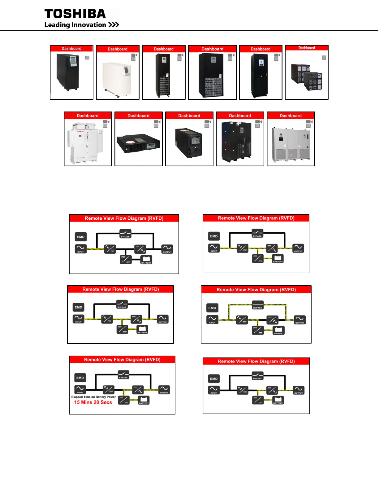
40 RemotEye 4 User Manual – 90988-007
1600XPi 1600XP 4300 4400 G9000 T1000
5000 (NEMA 3R) T1000 (1-3kVA) T1000 (1-3kVA) G2020 5000 (3P1)
(Rackmount) (Tower)
Figure 5-6 Default UPS Pictures
Remote View Flow Diagram (RVFD): This widget displays a graphical diagram of the current UPS mode
(Startup, Online, CVC, Bypass, Backup, Battery Test, Pre-Charge, Gate-Check or Shutdown mode)
Startup Mode Online Mode
CVC Mode Bypass Mode
Backup Mode Battery Test Mode

RemotEye 4 User Manual – 90988-007 41
Pre-Charge Mode Gate-Check Mode
Shutdown Mode
Figure 5-7 Remote View Flow Diagrams (RVFD)
Click on each Icon in the RVFD to display the parameters for that section of the UPS in the Dynamic Block widget.
Comprehensive: (Dynamic Block) This widget displays the dynamic data from the RVFD. Clicking an icon on the
RVFD will cause only those parameters to be displayed. Otherwise the summary parameters are displayed. This
widget cannot be replaced.
1600XP/XPi 4300 4400/5000 G9000 T1000
Figure 5-8 Dynamic (Comprehensive) Block by Series
UPS Identification: This widget displays the UPS Manufacturer, UPS Typeform (Specific model number), UPS
Serial Number, and UPS System Name assigned by the user. This information is constant. This widget cannot be
replaced.
History/Trend Block: This block can only be set to display either the History Graph or Trend Graph. This block
cannot be replaced.
History Block – (Default) The time can be controlled by the user by entering the Start-Date and End-Date. The
graph will display any and all of the parameters selected from the parameter list above the Start/Stop Date line. The
parameters include Input Voltage, Input frequency, Output Voltage, Output Frequency and Output Current.
Tracking of any of the parameters can be turned off by clicking the selection name.
Trend Block – The Trend Block displays the current values from the parameter list and updates per the user-selected
sampling rate.

42 RemotEye 4 User Manual – 90988-007
History Block Trend Block
Figure 5-9 History/Trend Blocks
5.2.1 Customizing the Dashboard Layout
Users can customize the Dashboard layout of information widgets.
1. First log in as an administrator either through the log in web page, or the log in button if signed in as guest,
see Figure 5-10 Login to Edit Dashboard.
User Login Guest Login
Figure 5-10 Login to Edit Dashboard
2. Login, then press the Edit Dashboard button. (Figure 5-11)
Figure 5-11 Edit Dashboard Button
The dashboard will place a white “X” in the upper right corner of all widgets that can be edited. (See Figure 5-12)

RemotEye 4 User Manual – 90988-007 43
Figure 5-12 Edit Dashboard Mode
White “X”
Selectable
Reserved
Reserved
Reserved
Reserved
Selectable
Selectable
Selectable
Selectable
Selectable

44 RemotEye 4 User Manual – 90988-007
Figure 5-13 Edit Dashboard Mode - Drop-down Menu
3. Click the white “X” in the upper right-hand corner of the dashboard widget. (See Figure 5-12.)
4. A drop down menu displays the available widget selection excepting those widgets already displayed on the
dashboard. Click to select one the entries from the drop down menu. (See Figure 5-13.)
5. Click on the in the upper right-hand corner to load the widget highlighted in the drop-down menu.
WEB NAVIGATION
The RemotEye 4 web page has six drop-down menus (See Figure 5-14 and Figure 5-15):
DASHBOARD – There is no drop-down menu. Clicking this reloads the dashboard.
UPS MONITORING – Drop-down menu allows monitoring of specific categories of UPS Parameters.
UPS MANAGEMENT – Drop-down menu allows user management of UPS functions. The menu only
shows when a UPS is connected to the RemotEye 4.
SETTINGS – Drop-down menu allows setting the protocols/parameters/network addresses for the
RemotEye 4.
EMD – Drop-down menu allows set up of monitoring and alarms for the Environmental Monitoring
Device(s) (EMD).
NOTE: The EMD must be connected and properly configured to use this menu.
Place the pointer over each menu header. The drop-down menu choices will be displayed. (See Figure 5-14) Click
on the menu header to open the drop-down menu.
The choices in each Dropdown menu are shown in Figure 5-14.
Dropdown
Menu

RemotEye 4 User Manual – 90988-007 45
Figure 5-14 Drop-Down Menus
The UPS MONITORING, UPS MANAGEMENT, and SETTINGS drop-down menus open a three panel display,
as shown in Figure 5-15. The drop-down menu opens on the left side of the display, the selection detail panel opens
in the middle, and the Description panel opens on the right side of the display.
Figure 5-15 SETTINGS Web Page
5.3.1 UPS MONITORING Drop-down Menu
Ref. Figure 5-14 Drop-Down Menus.
This is a comprehensive of all drop-down menus. Note: Not all options apply to all models of UPS’s.
UPS Data General: UPS hardware and software version information.
UPS Data Display: UPS Display firmware version information.
UPS Data Other: Internal communications and port status.
Input Parameter: Input Voltage/Current/Frequency/Power/etc.
Selection Settings
SETTINGS
Drop-down
Menu
Setting
Description
Drop-down
Menu
Headers

46 RemotEye 4 User Manual – 90988-007
Output Parameter: Output Voltage/Current/Frequency/Power/etc.
Bypass Parameter: Output Voltage/Current/Frequency/Power/etc.
DC Bus Parameter: DC Bus Positive/Negative/Rated Voltage.
Battery Parameter: Battery Voltage/Current/Charging Current/detection levels/etc.
UPS Home Group: Displays the Name/IP Address/UPS Mode of all RemotEye devices in the same
network.
Protected Clients: Displays the Name/IP Address/Shutdown Delay of the current protected
computers/servers.
Alert Center: Date/Event
History Logs: Individual logs for System/Inverter/Backup Operations as well as Total number of
Overloads/Backups/Faults/etc.
5.3.2 UPS MANAGEMENT Drop-down Menu
Ref. Figure 5-14 Drop-Down Menus
This is a comprehensive of all UPS MANAGEMENT options. Note: Not all options apply to all models of UPS’s.
UPS Configuration General: Set Password/System Name/Rated in-Out Voltage/Battery Data
UPS Configuration Display: Set Sleep Timer and Buzzer Status.
UPS Control: Adjust output voltage, enable RMTI-4 Control, Configure Startup/Restart/Transfer delay
Battery Test: Start/Elapsed Time, set Test Schedule, Test Results
UPS Shutdown Events: Shutdown Events, Shutdown Action, Shutdown Delay
Non/Recurring On/Off: UPS Shutdown Scheduler.
5.3.3 SETTTINGS Drop-down Menu
These settings can be accessed from the SETTINGS menu (Ref. Figure 5-14 Drop-Down Menus):
(This is a comprehensive of all SETTINGS options. Note: Not all options apply to all models of UPS’s.)
SNMP Settings: Configure RemotEye 4 to work with SNMP.
Modbus Settings: Configure RemotEye 4 to work with Modbus TCP or RTU.
BACnet Settings: Configure RemotEye 4 to work with BACnet IP or MSTP.
Email Settings: Enter email’s to receive warnings/ notifications
RADIUS Settings: Configure RemotEye 4 to work with the RADIUS server.
Interface Settings: Configure RemotEye 4 to work with either the RS-232 or RS-485 serial port. Used for
either BACnet MSTP or Modbus RTU.
Configuration Capture Tool: Record snapshot of current configuration. Used to configure other
RemotEye 4s.
Wireless: Configure RemotEye 4 to work with wireless features.
Reminders: Set reminders
RemotEye 4 System Settings: Edit RemotEye 4 configuration settings that were entered during initial
setup.
5.3.4 EMD Drop-down Menu
Ref. Figure 5-14 Drop-Down Menus
EMD Configuration: Set the parameters and limits for the optional EMD device.
5.3.5 {Username} Drop-down Menu
Ref. Figure 5-14 Drop-Down Menus
Edit Dashboard: Enables rearranging/replacing some of the widgets on the Dashboard.
Logout: Exit the ADMIN mode.

RemotEye 4 User Manual – 90988-007 47
6 PROTOCOL SETUP
SNMP SETUP
To configure the RemotEye 4 for a SNMP network
1. Click on the SETTINGS menu header (Figure 5-15), then click on “SNMP Settings” in the drop-down
menu.
2. Fill in the SNMP settings in the SNMP Settings panel. For SNMP Traps, select the appropriate settings under
SNMP TRAP Receivers by entering the IP address etc. and selecting from the corresponding drop-down
menus for Trap, Severity Level, and Version.
3. Click the Set button.
Figure 6-1 SNMP Settings Panel
The RemotEye 4 supports SNMP ver. 1, ver. 2c, and ver. 3. Any workstation with compat1ble SNMP management
software can manage/monitor a Toshiba UPS through RemotEye 4.

48 RemotEye 4 User Manual – 90988-007
6.1.1 Toshiba MIB Files
The MIB is a text file that defines a set of objects that are processed via a network protocol. These objects
determine what UPS parameters may be monitored and controlled using SNMP requests.
The RemotEye 4 implements standard MIB and the following MIBs for these TOSHIBA UPS models (MIB’s are
available on the included RemotEye 4 CD, or as a download from www.tic.toshiba.com):
1) TIC-RMTI4-T1000-MIB File
2) TIC-RMTI4-1600XP-MIB File
3) TIC-RMTI4-4300-MIB File
4) TIC-RMTI4-4400-MIB File
5) TIC-RMTI4-G9000-MIB File (Note: Also compatible with G2020 UPS)
6) TIC-RMTI-5000-N3R-MIB File
7) TIC RMTI-5000-3P1-MIB File
8) TIC-RMTI4-SYS-MIB File
6.1.2 NMS (Manager) Settings
There are two areas of consideration when coordinating an NMS with a RemotEye 4. First, the Manager software
on the NMS must be prepared to handle the RemotEye 4 Management Information Base (MIB), and second, the
Manager must be configured to receive any traps the RemotEye 4 sends.
6.1.2.1 Import the MIB Files
The MIB files are contained on the factory-supplied CD-ROM. These files describe the information that is
attainable from each Toshiba UPS.
The Toshiba MIB files must be manually entered (imported or compiled) into the Manger database. For instruction
on incorporating private MIB files into the Manager, consult the Manager Software documentation.
6.1.2.2 MIB Import Example
This example shows how to incorporate the Toshiba MIB into the Manager application HP OpenView Workgroup
Node Manager. The software runs on the Windows platform.
Launch HP OpenView Workgroup Node Manager.
From the Control pull down menu, click SNMP Manager Manage Database Select (map to the MIB file,
TIC-RMTI4-1600XP-MIB.mib, on the included CDROM) click ADD.
Click “Close” to close the SNMP Manager Database.
6.1.2.3 Specifying Trap Receivers
To send traps to an NMS (Network Management System), the NMS IP Address must be specified in the SNMP
Traps Receiver Table.
MODBUS TCP/IP OR BACNET IP SETUP
The SETTINGS webpage provides ready access to configuring the RemotEye 4 for the supported protocols.
6.2.1 Configure for Modbus TCP/IP
Ref. Figure 6-2 Modbus TCP/IP and BACnet IP Configuration Panels
1. On the home page dashboard, click on the SETTINGS menu at the top of the page. This will bring up the
SETTINGS drop-down menu. (See Figure 5-14.)
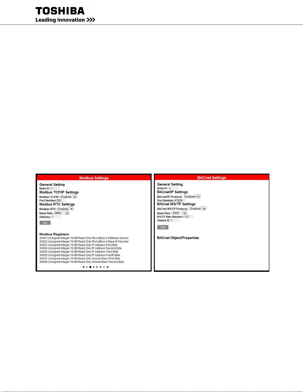
RemotEye 4 User Manual – 90988-007 49
2. In the SETTINGS drop-down menu click on “Modbus Settings” the selected entry text will turn RED.
3. Look In the Protocol Settings Panel titled “Modbus Settings”. Under “Modbus TCP/IP Settings” set
Modbus TCP/IP to Enabled
4. Under “Modbus RTU Settings” set Modbus RTU to Disabled.
5. Click on the Set button.
6. Continue with the RemotEye configuration.
6.2.2 Configure for BACnet IP
Ref. Figure 6-2 Modbus TCP/IP and BACnet IP Configuration Panels
1. On the home page dashboard, click on the SETTINGS menu at the top of the page. This will bring up the
SETTINGS drop-down menu . (See Figure 5-14, Figure 6-2)
2. In the SETTINGS drop-down menu click on “BACnet Settings” the selected entry text will turn RED.
3. Look In the Protocol Settings Panel titled “BACnet Settings”. Under “BACnet IP Settings” set BACnet
IP Protocol to Enabled
4. Under “BACnet MS/TP Settings” set BACnet MS/TP Protocol to Disabled.
5. Click on the Set button.
6. Continue with the RemotEye configuration.
Figure 6-2 Modbus TCP/IP and BACnet IP Configuration Panels

50 RemotEye 4 User Manual – 90988-007
MODBUS RTU OR BACNET MS/TP SETUP
6.3.1 Configure for Modbus RTU
Serial communication protocols require additional configuration with the INTERFACE configuration panel. Ref.
Table 12-6 Pin-outs for RS-485 (Phoenix) Connector
HARDWARE CONNECTIONS:
1. Wire the RemotEye 4 Phoenix connector for the RS-485 Serial port to the serial input cables as follows:
Figure 6-3 RemotEye 4 RS-485 Data and GND Cabling
The RS-485 Signal range is:
Input voltage range: 0 to 5 Volts
Output voltage range: -7 to 12 Volts
SOFTWARE CONFIGURATION:
2. On the home page dashboard, click on the SETTINGS menu at the top of the page. This will bring up the
SETTINGS drop-down menu. (See Figure 6-4.)
3. In the SETTINGS drop-down menu click on “Interface Settings” the selected entry text will turn RED.
3.1. If using RS-485
3.1.1. Under “RS-485 Interface Settings” set RS-485 Interface (Enable/Disable) to “Enabled”, and set
Define RS-485 Interface Protocol to “Modbus”.
3.1.2. Under “RS-232 Interface Settings” set RS-232 Interface (Enable/Disable) to “Disabled”, and set
Define RS-232 Interface Protocol to “Disabled”.
3.2. If using RS-232
3.2.1. Under “RS-232 Interface Settings” set RS-232 Interface (Enable/Disable) to “Enabled”, and set
Define RS-232 Interface Protocol to “Modbus”.
3.2.2. Under “RS-485 Interface Settings” set RS-485 Interface (Enable/Disable) to “Disabled”, and set
Define RS-485 Interface Protocol to “Disabled”.
Figure 6-4 Interface Settings for Modbus RTU
DATA +
DATA –

RemotEye 4 User Manual – 90988-007 51
4. In the SETTINGS drop-down menu click on “Modbus Settings” the selected entry text will turn RED.
5. Look in the Protocol Settings Panel titled “Modbus Settings”. Under “Modbus RTU Settings” (See Figure
6-5)
5.1. set Modbus RTU to “Enabled”,
5.2. Baud Rate to the system baud rate (Default: 9600),
5.3. Address to the unit address (Default: 1).
6. Under “Modbus TCP/IP Settings” set Modbus TCP/IP to “Disabled”.
7. Click the Set button.
Figure 6-5 Modbus Settings for Modbus RTU
8. Configure the Connection Setup with master as follows:
8.1. Connection: Serial Port
8.2. Port Settings: Port 1, 9600 Baud, 8Data bits, Non Parity, 1 Stop bit
8.3. Mode: RTU
8.4. Slave ID: 1 (There can be from 1-247 Slave units, each with a unique ID, connected to each Master unit.)
9. Set the Read/Write Definition (E.g. the Read registers are 30001 – 30030) (Figure 6-6):
Figure 6-6 MODbus Read/Write Definitions

52 RemotEye 4 User Manual – 90988-007
Figure 6-7 Example - MODbus Poll for 1600XP
6.3.2 Configure for BACnet MS/TP
Serial communication protocols require additional configuration with the INTERFACE configuration panel.
Ref. Table 12-6 Pin-outs for RS-485 (Phoenix) Connector.
HARDWARE CONNECTIONS:
1. Wire the RemotEye 4 Phoenix connector for the RS-485 Serial port to the serial input cables as follows:

RemotEye 4 User Manual – 90988-007 53
Figure 6-8 RemotEye 4 RS-485 Data and GND Cabling
The RS-485 Signal range is:
Input voltage range: 0 to 5 Volts
Output voltage range: -7 to 12 Volts
SOFTWARE CONFIGURATION:
2. On the home page dashboard, click on the SETTINGS hotlink at the top of the page. This will bring up the
SETTINGS drop-down menu . (See Figure 6-9.)
3. In the SETTINGS drop-down menu click on “Interface Settings” the selected entry text will turn RED.
3.1. If using RS-485
3.1.1. Under “RS-485Interface Settings” set RS-485 Interface (Enable/Disable) to “Enabled”, and set
Define RS-485 Interface Protocol to “BACnet”.
3.1.2. Under “RS-232Interface Settings” set RS-232 Interface (Enable/Disable) to “Disabled”, and set
Define RS-232 Interface Protocol to “Disabled”.
3.2. If using RS-232
3.2.1. Under “RS-232Interface Settings” set RS-232 Interface (Enable/Disable) to “Enabled”, and set
Define RS-232 Interface Protocol to “BACnet”.
3.2.2. Under “RS-485Interface Settings” set RS-485 Interface (Enable/Disable) to “Disabled”, and set
Define RS-485 Interface Protocol to “Disabled”.
Figure 6-9 Interface Settings for BACnet MS/TP
4. In the SETTINGS drop-down menu click on “BACnet Settings” the selected entry text will turn RED.
5. Look in the Protocol Settings Panel titled “BACnet Settings”. (See Figure 6-10)
5.1. Under “BACnet MS/TP Settings” set BACnet MS/TP Protocol to “Enabled”,
5.2. Set the Baud Rate to the system baud rate (Default: 9600),
5.3. Set the MS/TP Max Masters (Default: 127),
5.4. Set the Station ID (Default: 1).
6. Under “BACnet IP Settings” set BACnet IP Protocol to “Disabled”.
7. Click on the Set button.
DATA +
DATA –

54 RemotEye 4 User Manual – 90988-007
Figure 6-10 BACnet Settings for BACnet MS/TP
8. Set the BACnet master port parameters:
8.1. COM Port
8.2. Baud Rate:
8.3. Station
8.4. Max Master
Note: For additional RS-485 Connection Information, reference Appendix P
6.3.3 Suggested Communication Settings
All Protocols (Modbus TCP, Modbus RTU, BACnet MS/TP, BACnet IP):
Reply Timeout: 500ms
Delay Time: 1 second
Min Delay between polls:
If you set this value lower than 1 second the time gap between response and a new request cannot be
guaranteed. This is because the scheduler switch tasks every 10 - 20ms.

RemotEye 4 User Manual – 90988-007 55
7 OPTIONAL FEATURES SETUP
RADIUS CONFIGURATION
This page allows the administrator to input the RADIUS server parameters. RADIUS is networking protocol that
provides a centralized authentication to use its network service. The RemotEye 4 has the ability to communicate
with a RADIUS server which will determine if the user has access to RemotEye 4 services.
Click on Settings at the top of the webpage, and on the dropdown menu select RADIUS Settings.
Here are the parameters required to enable the Radius feature:
RADIUS UDP Port – This field shows the default UDP port for RADIUS Authentication. (Read-Only)
Primary RADIUS Server – This field allows the administrator to set the IP address of the primary
RADIUS server.
Secondary RADIUS Server – This field allows the administrator to set the IP address of the secondary
RADIUS server, in case the primary server does not respond.
Share Secret of Primary Server – This allows the administrator to input the case-sensitive text sting
(password) into the text field to access the RADIUS server.
Share Secret of Secondary Server – This allows the administrator to input the case-sensitive text sting
(password) into the text field to access the RADIUS server.
Packet Timeout Interval (sec) – User can set the Packet Timeout Interval in seconds.
Packet Retry Times – User can set the packet retry times.
EMAIL NOTIFICATION
This page allows the administrator to set the RemotEye 4 email notification configuration parameters.
Click on Settings at the top of the webpage, and on the dropdown menu select Email Settings.
SMTP Server – This field allows the administrator to set the IP Address or Hostname of a Simple Mail
Transfer Protocol (SMTP) mail server that will be used to send email messages from RemotEye 4. If
entering a Hostname, the Domain Name Server (DNS) IP address is required in the DNS field.
SMTP Port Number – Port for the SMTP Server.
(Authentication – Authentication is now handled automatically between RemotEye and the mail server.
Supported protocols are NTML, CRAM-MD5, and LOGIN.)
User Account –This field allows the administrator to enter User Account login name of the SMTP mail
server.
User Password –This field allows the administrator to enter User Account password of the SMTP mail
server.
Note: Not all SMTP Servers require login name and password. Please check with SMTP administrator.
Sender Email Address - This field will be used as the sender's email address.
DNS IP Address –This field allows the administrator to set the IP address of the network DNS server if a
Hostname is entered for the Mail Server. Otherwise, this field can be 0.0.0.0.
Send Daily Status Report At (HH:MM) – This field allows the administrator to set the time to send a
Daily Status report to the email address recipients that are selected to receive Daily Status Reports. The
time is set in a 24-hour format HH:MM.
Email Receivers
Fill in receivers:
- No. – Recipient’s list number (1-8)
56 RemotEye 4 User Manual – 90988-007
- Mail Account – Set the E-mail address of the recipients who will receive the events or/add the daily
status reports.
- Mail Type – This field allows the administrator to select the mail type:
o None – Disable option to send email to recipients.
o Events – Current events will be sent to recipients.
NOTE: System will label each event email with the system Name and Location, in the format:
systemName@SystemLocation (“systemName” and “SystemLoaction” can be set in the RemotEye
4 Configuration menu.
o Daily Status – Logs selected by administrator will be sent daily to the email recipients at the
designated time.
o Events with Status – Events along with logs selected by the administrator will be sent to email
recipients when events occur.
- Severity Level – This field allows the administrator to select kind of notices each recipient receives.
o Informational: Refers to changes in the state of the UPS. This is based on which “Informational”
alarms are selected in the “UPS Configuration General” page. Will also receive Warning and fault
alarms.
o Warning: UPS has encountered a non-critical abnormal condition that requires attention. This is
based on which “Warning” alarms are selected in the “UPS Configuration General” page. Will
also receive fault alarms.
o Fault: UPS has encountered a critical abnormal condition and requires attention. This is based on
which “Fault” alarms are selected in the “UPS Configuration General” page. Refer to the manual
for possible causes and solutions. Will only receive fault alarms.
- Description – Allows the administrator to set the description of the recipients.
- Select the logs to be attached to the daily status emails – (See Table 7-1 Daily/Event Status Logs)
- Select the logs to be attached to the events status emails - (See Table 7-1 Daily/Event Status Logs)
Log Options for each UPS Series are:
Table 7-1 Daily/Event Status Logs
Daily/Event Status Logs
Log
T1000
1600XP/XPi
4300
4400/5000
N3R
G9000/
G2020
T1000
(1-3kVA)
5000
3P1
General Records Log
Y Y Y Y N/A
Y
N/A
Extended General Records Log
Y Y Y Y Y Y Y
UPS Events Log
Y Y Y Y Y Y Y
UPS History Log
N/A
N/A
N/A
N/A Y N/A
Y
UPS Extended Log
N/A
N/A
N/A
N/A Y N/A
Y
Test Log Y Y
N/A
N/A
N/A
N/A
N/A
Backup Log
Y Y Y Y N/A
N/A
Y
Fault Log Y Y Y Y
N/A
N/A
Y
Operation Log
Y Y Y Y N/A
N/A
Y
Warning Log
Y Y N/A Y N/A
N/A
Y
System Setting Log
Y Y N/A
N/A
N/A
N/A
Y
RemotEye 4 Events Log
Y Y Y Y Y
Y
N/A
EMD History Log
Y Y Y Y Y
Y
N/A
EMD Extended History Log
Y Y Y Y Y
Y
N/A

RemotEye 4 User Manual – 90988-007 57
REMINDERS
Reminders of system tasks or other notes can be set to send flags and/or emails to selected individuals at designated
times/dates.
Click on Settings at the top of the webpage, and on the dropdown menu select Reminders.
WIRELESS SYSTEM SETTINGS
Figure 7-1 Wireless System Settings View
Note: Seperately sold wireless adapter, “Edimax EW-7811Un”, is necessary for wireless functionality. (Edimax is a
trademark of Edimax Technology Co., Ltd.)
REMOTEYE 4 SYSTEM SETTINGS
The editable system settings for RemotEye 4 are listed below:
1. Date & Time Settings
2. System & Network Settings
2.1. RemotEye 4 information
2.2. RemotEye 4 IPv4 Setting
2.3. RemotEye 4 IPv6 Settings
2.4. Protocols Settings
2.4.1. DHCP Control
2.4.2. Telnet
2.4.3. SSHv2
2.4.4. Network Upgrade
2.4.5. UPnP: Enabled/Disabled
2.4.6. HTTP Authentication Method
3. User Profiles
3.1. Index
USB Wireless Adapter Connection

58 RemotEye 4 User Manual – 90988-007
3.2. User Name
3.3. Password
3.4. Email
3.5. Access Type
3.6. Guest Mode
3.7. Login Screen
4. Firewall Settings
4.1. Index
4.2. IP Address
4.3. Mask
4.4. Accept/Reject
5. Check for Update
5.1. Current Firmware:
5.2. New update Available
5.3. Auto Update
5.4. Restore/Save RemotEye 4 Settings
5.5. Reset RemotEye to Default
EMD (ENVIRONMENTAL MONITORING DEVICE)
The optional Environmental Monitoring Device (EMD) provides real time comprehensive remote monitoring of
environment temperature, environment humidity, and other environmental conditions via a web browser and SNMP.
The EMD also provides two user-defined dry contacts for additional environmental monitoring. These dry contacts
can be used with devices that provide normally-open or normally-closed results, such as door sensors, smoke
detectors, motion detectors, and liquid detectors.
The EMD is connected to the RemotEye 4 using an Ethernet cable. One end of the Ethernet cable is connected to the
RJ45 port of the EMD and the other end to the “EMD” port of the RemotEye 4.
Note: The EMD module is separate device which can be purchased from a Toshiba UPS distributor.

RemotEye 4 User Manual – 90988-007 59
7.6.1 EMD Installation
This section explains the how to setup/install the EMD to RemotEye4.
1. Use the Cat5 (straight) cable and connect one end to the “010101” port on the EMD.
2. Plug the other end of the Cat5 (straight) cable to the “EMD” port of the RemotEye 4.
3. Make sure that the green “Communication Status” LED on the EMD blinks periodically. If the LED does
not blink, verify that the Cat5 cable is functional.
4. Check the “EMD Setup” under the “EMD Configuration” page and ensure it is set to “Auto”.
5. Go to SETTINGS -> Interface Settings and enable "RS-232 Interface (Enable/Disable)" and set the
"Define RS-232 Interface Protocol" to "EMD" and press the "Set" button.
Figure 7-2 EMD RemotEye 4 Installation
7.6.2 EMD Parameters
This page gives a snapshot of all EMD parameters; the parameters will be updated automatically every 5 seconds.
The text color of the parameter indicates its status based on the administrator-configurable threshold.
The list below indicates the parameter status.
Table 7-2 EMD Layout and Indicators
EMD Comprehensive View
Parameter
Value
EMD Name
(Assigned ID)
Displays the EMD Name when the EMD is connected and working
correctly.
“Disable” – When the EMD is connected but the “Device Status” is
Disabled in the EMD configuration settings.
“Unknown” – When the EMD is not connected to the RemotEye 4.
EMD Temperature (°C/°F)
(Module Temperature in °C/°F)
EMD Humidity (%)
(Relative Humidity in %)
EMD Alarm-1
Alarm 1 status: Normal/Alarm
EMD Alarm-2
Alarm 2 status: Normal/Alarm
EMD Parameter value text will be displayed in one of four colors:
GREEN: “Normal” status (Within upper and lower “Warning” limits.)
YELLOW: “Warning” status (Exceeds upper or lower “Warning” limits but within “Critical” limits.)
RED: “Critical” status (Exceeds upper or lower “Critical” limits.)
GREY: “Unknown” value (Disabled or not connected.)
The EMD provides the measurements for room (ambient) temperature, room (ambient) humidity, and two alarms
(two dry contacts). The warning/critical thresholds can be setup via the "EMD Configuration" panel.

60 RemotEye 4 User Manual – 90988-007
7.6.3 EMD Configuration
This page allows administrator to configure all necessary parameters/settings of an EMD.
Sensors
The sensors column parameters consist of the following:
1. Temperature (°C/°F)
2. Humidity (%)
3. Alarm-1 (Sec)
4. Alarm-2 (Sec)
5. Device Status
Set Point (Low)
The low threshold(s) at which the sensor (temperature or humidity) will trigger an alarm(s). The EMD can be
configured to activate at two set points on the low limit Warning, and Critical. If the checkbox is not filled, the
threshold is disabled and the alarm will not be triggered. The valid range for the Temperature threshold setting is
5C to 65C, and for Humidity threshold setting is 5% to 95%.
Set Point (High)
The high threshold(s) at which the sensor (temperature or humidity) will trigger an alarm(s). The EMD can be
configured to activate two high set points Warning, and Critical. If the checkbox is not filled, the threshold is
disabled and the alarm will not be triggered. The valid range for the Temperature threshold setting is 5C to 65C,
and for Humidity threshold setting is 5% to 95%.
Hysteresis
A sensors value could float around its threshold triggering multiple nuisance alarms. Setting the hysteresis will help
to prevent the alarm bouncing between active and inactive. For example, if the High Warning threshold set point is
40C and hysteresis is 3, then the alarm will activate when the value reaches 40C but it will not become inactive
again until the sensor value reaches 37C.
For the contact alarm sensors (Alarm-1 and Alaarm-2), the hysteresis can be used to adjust the sensitivity of an
alarm. The alarm will be active or inactive only after the alarm stays in the same state for the duration of the
hysteresis value (in seconds). For example, if the hysteresis is 5 for an alarm, the alarm will NOT activate until the
same state has persisted for 5 seconds. This ruling also applies in reverse so that the alarm has to stay in an inactive
state for 5 seconds before the sensor status is recorded as normal.
Calibration Offset
If the measurement value of a sensor does not, for whatever reason, comply with the actual environment, the
“Calibration Offset” setting can be configured to adjust the final value of the sensor. For example, if a sensor reports
43% humidity for a 45% humidity environment, the administrator can configure the humidity offset as 2% so the
sensor can then adjust its final value to 45%.
Alarm-1 (Sec) & Alarm-2 (Sec)
If an alarm sensor (water leak, security, etc.) is connected to the EMD, the administrator can configure the alarm as
“Disabled”, “Normal Open”, “Normal Close”. A “Disabled” setting will mean the alarm is inactive.
“Normal Open” and “Normal Close” are used for a two-wire detector that will emulate an open/close state. When
the wires are closed to “loopback” (the signal for the sensor), the sensor will detect the state as closed. The sensor
will NOT activate the alarm for 'Normal Close' in this case, although the alarm will be activated if configured as
“Normal Open”.
EMD Setup
The EMD can be configured as “Disabled” or “Auto”.
The setup should be configured as “Disabled” if an EMD is not attached to the port or would like to turn of the EMD
feature.
The EMD type will be auto detected by the RemotEye 4 if configured as “Auto” and if the EMD is plugged into the
EMD port.

RemotEye 4 User Manual – 90988-007 61
8 MOBILE-FRIENDLY WEB INTERFACE
DISPLAY AND NAVIGATION
Users that have the RemotEye 4 card and their mobile phone or tablet in the same network can open the RemotEye 4
mobile web interface from their mobile/tablet internet browsers. The mobile web interface includes basic
information about the UPS. The basic parameters for each UPS will consist of Input, Output, Alert Center and
Protected Clients. See Figure 8-1 Mobile Webpage by Product Line
1600XP 1600XPi 4300 4400
G9000/G2020 T1000 (6kVA) T1000 (1-3kVA) 5000 (NEMA 3R) 5000 (3P1)
Figure 8-1 Mobile Webpage by Product Line
Navigate the Mobile Webpage by using the standard finger drag method to scroll (up and down) or pan (side to
side).
The home page display for the mobile app is shown in Figure 8-1. Tap on the drop down menu
icon (three horizontal, parallel lines) at the top left side of the display to open the drop-down
menu.
H3BG2L060C61T
1600XPi 6KVA
Typeform:
T1S0A1000AXA
UPS Model:
T1000 1kVA
UPS Name:
Computer Room
Input Power Config: 120V/60Hz
Input # of Lines:
1
Input V:
114 (95%)
Input Current Amps:
3.8 (51%)
Input Hz:
59.0
Input Apparent VA:
458
Output Power Config: 120V/60Hz
Output # of Lines:
1
Output V:
114 (95%)
Output Hz:
60.0
OUVL (%):
90
OOVL (%):
110
Typeform:
T1S0A6000GXG
UPS Model:
T1000 6kVA
UPS Name:
Computer Room
Typeform:
5CP0G030KWWK
UPS Model:
5000 NEMA 3R 30kVA
UPS Name:
Control Room
Typeform:
50P0K050KWAA
UPS Model:
5000 3P1 50kVA
UPS Name:
Control Room
Input V: 480V/480V/480V
Input V LN:
277/277/277
Input Voltage %:
100/100/100
Input Current:
0.0/0.0/0.0
Input Active Total Watts:
0.0
Input Active Watts:
0/0/0
Output V: 120V
Output Voltage %:
100
Output Current:
0.0
Output Load %:
0.0
Output Hz:
60

62 RemotEye 4 User Manual – 90988-007
The drop-down menu offers five selections: Home, Input Parameters, Output Parameters, Alert Center, and
Protected Clients.
Selecting Input Parameters, Output Parameters, Alert Center, and Protected Clients will open a webpage
giving more detailed information on that topic. See Figure 8-2 Input Parameters Mobile Webpage Examples
1600XP/XPi 4300 4400 G9000 T1000
Figure 8-2 Input Parameters Mobile Webpage Examples
ALERT CENTER
The alarm symbol, , will pop-up in the UPS Identification window header whenever there is an alert
generated by the UPS. Click on the drop-down menu and select Alert Center. More detailed information on the
alert will be displayed. (See Figure 8-3)
Figure 8-3 Example of Alert Center and Protected Clients
PROTECTED CLIENTS
This web page gives more detailed information on the Protected Clients parameters, including the client Name and
client IP address. (See Figure 8-3)

RemotEye 4 User Manual – 90988-007 63
9 REMOTEYE 4 CONSOLE MENU NAVIGATION
In cases where the GUI is not available, such as networks that restrict HTTP access, the RemotEye 4 can be
configured via the built-in console menu using a third-party terminal emulation software.
The table below provides an overview of the console menu structure (See Table 9-1). When navigating through
these menus, all alpha-numeric characters are acceptable, and are case-sensitive.
Table 9-1 Console Menu Tree
RemotEye 4 Menu Tree – Console
(1) RemotEye 4
Card Settings
(1) IP, Time, and
System Group
RemotEye 4 Card Version:
v1.0
Ethernet Address :
(1) IPv4 Group
(Default values shown)
(1) IP Address: (Default: 192.168.1.168)
(2) Gateway Address: Default: (192.169.1.1)
(3) Network Subnet:
(Default: 255.255.255.0)
(0) Return to previous menu
(2) IPv6 Group
(1) IP v6 Link Local Address: (Default:
FE80::2E0:D8FF:FEFF:AFE2)
(2) IPv6 Global Address: (Default:
2001:B182::2E0:D8FF:FEFF:A)
(3) IPv6 Prefix Length: (Default: 64)
(4) IPv6 Router Address: (Default:
FE80::218:E7EE:FEF4:BD26)
(0) Return to previous menu
(3) Date and Time Group
(1) System Date (mm/dd/yyyy):
02/12/2014
(2) System Time (hh.mm.ss):
21:56:43
(3) NTP Server:
(4) NTP Time Zone:
(5) Daylight Saving Time Control:
(0) Return to previous menu
(4) System Contact:
(Default: Technical Support Team)
(5) System Name:
(Default: TOSHIBA)
(6) System Location:
(0) Return to Previous
(2) Network
Control Group
(1) BOOTP/DHCP Control:
Enabled/Disabled
(2) Upgrade Control:
Enabled/Disabled
(3) Ping Control:
Enabled/Disabled
(1) RemotEye 4
Card Settings
(2) Network
Control Group
(4) UPnP Control:
Enabled/Disabled
(CONT)
(CONT)
(5) SNMP Control Group
(1) SNMP Control: Enabled/Disabled
(2) SNMP Port
(0) Return to previous menu

64 RemotEye 4 User Manual – 90988-007
RemotEye 4 Menu Tree – Console
(6) SMTP Control Group
(1) SMTP Control: Enabled/Disabled
(2) SMTP Port
(0) Return to previous menu
(7) SSH Control Group
(1) SSH Control: Enabled/Disabled
(2) SSH Port
(0) Return to previous menu
(8) Telnet Control Group
(1) Telnet Control: Enabled/Disabled
(2) Telnet Port
(0) Return to previous menu
(9) HTTP Control Group
(1) HTTP Control: Enabled/Disabled
(2) HTTP Port
(3) HTTP Authentication:
Local/RADIUS/Both
(0) Return to previous menu
(0) Return to previous menu
(3) Account
Control Group
(1) RADIUS Group
(1) RADIUS Port:
(2) RADIUS Server Settings
(3) Packet Timeout: 1
(4) Packet Retry: 3
(0) Return to previous menu
(2) Access Control Table
User Name | User Level
[1] Disabled
[2] to [8][
Command:
(1) Display one entry
(2) Modify one entry
(0) Return to previous menu
(3) Super User Group
(1) User Name:
(2) User Password: *
(0) Return to previous menu
(4) Guest Mode
Enabled/ Disabled
(5) Login Screen
(0) Return to Previous
(4) Email Group
(1) Mail Server:
(2) SMTP Port Number:
(3) User Account:
(4) User Password:
(5) DNS IP Address
(1) RemotEye 4
(4) Email Group
(6) Sender Email Address:
(CONT)
(CONT)
(7) Mail Subject Prefix:
(8) Mail Daily Status
Report At (hh:mm): 00.00

RemotEye 4 User Manual – 90988-007 65
RemotEye 4 Menu Tree – Console
(9) Mail Receiver Table
Mail Account | Description | Mail Type |
Event Level
[1] | None | Information |
[2] to [8]
Command:
(1) Display one entry
(2) Modify one entry
(3) Send Email Test
(0) Return to previous menu
(0) Return to Previous
(5) SNMP Group
(1)Trap Receiver Table
IP Address | Community/Name | Trap Type |
Severity | Description
[1] |None | Information
[2] to [8]
Command:
(1) Display one entry
(2) Modify one entry
(3) Send Test Trap
(0) Return to previous menu
(2) SNMPv3 USM Table
User Name | Auth Password | Auth Priv
Password | Privacy | Security
[1] |MD5 | DES | noAuthNoPriv
[2] to [8]
Command:
(1) Display one entry
(2) Modify one entry
(3) Send Test Trap
(0) Return to previous menu
(0) Return to previous
(6) Modbus Group
(1) Node ID: 1
(2) Modbus TCP/IP: Enabled/Disable
(3) Port Number: 502
(4) Modbus RTU: Enabled/Disabled
(5) Baud Rate: 9600/19200/38400/
57600/115200
(6) Address: 1
(0) Return to previous menu
(7) BACnet Group
(1) Node ID: 1
(2) BACnet/IP: Enabled/Disable
(3) Port Number: 47808
(1) RemotEye 4
(7) BACnet Group
(4) BACnet MS/TP: Enabled/Disabled
Card Settings
(CONT)
(5) Baud Rate: 9600/19200/
38400/57600/115200
(CONT)
(6) MS/TP Max Masters: 127
(7) Station ID: 1

66 RemotEye 4 User Manual – 90988-007
RemotEye 4 Menu Tree – Console
(0) Return to previous menu
(8) Interface Settings Group
(1) RS-232 Interface: Disabled/Enabled
(2) Define RS-232 Interface Protocol:
Modbus/BACnet/EMD
(3) RS-485 Interface: Disabled/Enabled
(4) Define RS-485 Interface Protocol:
Modbus/BACnet/EMD
(0) Return to previous menu
(0) Back to Main Menu
(2) Reset Configuration to Default
Are you sure? (y/n)
(Default: N or n)
(3) Restart RemotEye 4 Card
Agent restart? (y/n)
(Default: N or n)
(0) Exit
MAIN MENU DESCRIPTION
The Main Menu of the RemotEye 4 consists of the following options (See Figure 9-1)
1. RemotEye 4 Card Settings
2. Reset Configuration to Default
3. Restart RemotEye 4 Card
0. Exit
Press the number of the associated selection and press [Enter].
+====================================================================+
| Toshiba RemotEye 4 Configuration Utility |
| [Firmware v1.0] |
+====================================================================+
1. RemotEye 4 Card Settings
2. Reset Configuration to Default
3. Restart RemotEye 4 Card
0. Exit
Please Enter Your Choice =>
Figure 9-1 RemotEye 4 Console Main Menu

RemotEye 4 User Manual – 90988-007 67
REMOTEYE 4 CARD SETTINGS
Main Menu (1) RemotEye 4 Card Settings (See Figure 9-2).
The SNMP/WEB Card settings option provides access to the following group settings:
1. IP, Time and System Group
2. Network Control Group
3. Account Control Group
4. Email Group
5. SNMP Group
6. Modbus Group
7. BACnet Group
8. Interface Settings Group
0. Back to Main Menu
Press the number of the associated selection and press [Enter].
+==================================================================+
| Toshiba RemotEye 4 Configuration Utility |
| [RemotEye 4 Card Settings] |
+==================================================================+
1. IP, Time and System Group
2. Network Control Group
3. Account Control Group
4. Email Group
5. SNMP Group
6. Modbus Group
7. BACnet Group
8. Interface Settings Group
0. Back to Main Menu
Please Enter Your Choice =>
Figure 9-2 RemotEye 4 Card Settings Menu

68 RemotEye 4 User Manual – 90988-007
9.2.1 IP, Time and System Group
Main Menu (1) RemotEye 4 Card Settings (1) IP, Time and System Group (See Figure 9-3).
1. IPv4 Group
2. IPv6 Group
3. Date and Time Group
4. System Contact : Name of contact. (Default: Technical Support Team)
5. System Name : Name of system. This string serves as the RemotEye 4 Client Identifier (CID) in
DHCP systems. (Default: TOSHIBA)
6. System Location : Physical Location of System.
0. Return to previous menu
Press the number of the associated selection and press [Enter].
+===================================================================+
| Toshiba RemotEye 4 Configuration Utility |
| [IP, Time and System Group] |
+===================================================================+
SNMP/WEB Card Version : RemoteEye4 v1.0
Ethernet Address : 00:E0:D8:FF:B5:12
1. IPv4 Group
2. IPv6 Group
3. Date and Time Group
4. System Contact : Technical Support Team
5. System Name : TOSHIBA
6. System Location :
0. Return to previous menu
Please Enter Your Choice => 1
Figure 9-3 IP, Time and System Group Menu
9.2.1.2 IPv4 Group
Main Menu (1) RemotEye 4 Card Settings (1) IP, Time and System Group (1) IPv4 Group
(See Figure 9-4)
The IPv4 Group provides access to the network address settings listed below. The settings may be viewed or
changed from this screen. When using the Dynamic Host Configuration Protocol (DHCP), items 1 – 3 will be
retrieved automatically.
1. IP Address: RemotEye 4 IPv4 Address (Default: 192.168.1.168)
2. Gateway Address: Gateway address if a router is used. (Default: 192.168.1.1)
3. Network Subnet: Network mask for the RemotEye 4 network. (Default: 255.255.255.0)
0. Return to previous menu
Press the number of the associated selection and press [Enter].

RemotEye 4 User Manual – 90988-007 69
+===================================================================+
| IP, Time and System Group |
| [IPv4 Group] |
+===================================================================+
1. IP Address : 192.168.1.168
2. Gateway Address : 192.168.1.1
3. Network Subnet : 255.255.255.0
0. Return to previous menu
Please Enter Your Choice => 0
Figure 9-4 IPv4 Group Menu
9.2.1.3 IPv6 Group
Main Menu (1) RemotEye 4 Card Settings (1) IP, Time and System Group (2) IPv6 Group
(See Figure 9-5)
The IPv6 Group provides access to the network address setting listed below. The setting may be viewed or changed
from this screen. When using the Dynamic Host Configuration Protocol (DHCP), items 1 will be retrieved
automatically.
1. IPv6 Link-Local Address: (Default: FE80::2E0:D8FF:FEFF:AFE2)
2. IPv6 Global Address: (Default: 2001:B182::2E0:D8FF:FEFF:A)
3. IPv6 Prefix Length: (Default: 64)
4. IPv6 Router Address: (Default: FE80::218:E7EE:FEF4:BD26)
0. Return to previous menu
Press the number of the associated selection and press [Enter].
+===================================================================+
| IP, Time and System Group |
| [IPv6 Group] |
+===================================================================+
1. IPv6 Link Local Address:
2. IPv6 Global Address:
3. IPv6 Prefix Length:
4. IPv6 Router Address:
0. Return to previous menu
Please Enter Your Choice => 0
Figure 9-5 IPv6 Group Menu
9.2.1.4 Date and Time Group
Main Menu (1) RemotEye 4 Card Settings (1) IP, Time and System Group (2) Date and Time Group (See
Figure 9-6
The IPv4 Group provides access to the network address settings listed below. The settings may be viewed o
1. System Date (dd/mm/yyyy): The date and time format is MM/DD/YYYY, and HH:MM:SS respectively.
2. System Time (hh:mm:ss): RemotEye 4 supports the Network Time Protocol (NTP). These two features
enable the UPS to synchronize its date and time with a NTP server.
3. NTP Server
4. NTP Time Zone : 27
5. Daylight Saving Time Control : Disabled
0. Return to previous menu
Press the number of the associated selection and press [Enter].

70 RemotEye 4 User Manual – 90988-007
+===================================================================+
| IP, Time and System Group |
| [Date and Time Group] |
+===================================================================+
1. System Date (dd/mm/yyyy) : 02/12/2014
2. System Time (hh:mm:ss) : 21:56:43
3. NTP Server : 10.98.122.12
4. NTP Time Zone : [GMT 00:00] Greenwich Mean Time :
Dublin, Edinburgh, Lisbon, London
5. Daylight Saving Time Control : Disabled
0. Return to previous menu
Please Enter Your Choice => 0
Figure 9-6 Date and Time Group Menu
9.2.2 Network Control Group
Main Menu (1) SNMP/WEB Card Settings (2) Network Control Group (See Figure 9-7)
The Network Control Group provides access to the network interaction settings listed below.
1. BOOTP/DHCP Control : Enables or disables automatic gateway and IP address selection. (Default:
Enabled)
2. Upgrade Control: Enables/Disables Firmware updates the Trivial File Transfer Protocol image upgrade.
When disabled, RemotEye 4 will block any attempts to upgrade. (Default: Enabled)
3. Ping Control: Ping Echo is the RemotEye 4’s response to an internet availability inquiry. (Default: Enabled)
4. UPnP Control: Universal Plug-n-Play protocol (Default: Enabled)
5. SNMP Control Group:
6. SMTP Control Group:
7. SSH Control Group:
8. Telnet Control Group
9. HTTP Control Group: Enables/Disables the web password protection feature. When enabled, a password is
required to access RemotEye 4 through the web, and write privileges are automatically assumed. When
disabled, any machine can access RemotEye 4 over the web, but a password is required prior to assuming
write privileges. (Default: Enabled). Also Set HTTP Authentication to Local, Radius, or Both.
0. Return to previous menu

RemotEye 4 User Manual – 90988-007 71
Press the number of the associated selection and press [Enter].
+===================================================================+
| Toshiba RemotEye 4 Configuration Utility |
| [Network Control Group] |
+===================================================================+
1. BOOTP/DHCP Control : Enabled/Disabled
2. Upgrade Control : Enabled/Disabled
3. Ping Control : Enabled/Disabled
4. UPnP Control : Enabled/Disabled
5. SNMP Control Group
6. SMTP Control Group
7. SSH Control Group
8. Telnet ControlGroup
9. HTTP ControlGroup
0. Return to previous menu
Please Enter Your Choice => 0
Figure 9-7 Network Control Group Menu
9.2.2.2 SNMP Control Group
Main Menu (1) RemotEye 4 Card Settings (2) Network Control Group (6) SNMP Control Group (See
Figure 9-7)
The SNMP Control Group provides access to the SNPM settings listed below.
1. SNMP Control : Enables/Disables SNMPv3 security. (Default: Enabled)
2. SNMP Port: Enter SNMP port number. (Default: 161)
1. Return to previous menu
Please Enter Your Choice => 0Press the number of the associated selection and press [Enter].
+===================================================================+
| Toshiba RemotEye 4 Configuration Utility |
| [SNMP Control Group] |
+===================================================================+
1. SNMP Control : Enabled
2. SNMP Port : 161
0. Return to previous menu
Please Enter Your Choice => 0
Figure 9-8 SNMP Control Group
9.2.2.3 SMTP Control Group
Main Menu (1) RemotEye 4 Card Settings (2) Network Control Group (6) SMTP Control Group (See
Figure 9-7)
The SMTP Control Group provides access to the SNPM settings listed below.
1. SMTP Control: Enables/Disables SMTP. (Default: Enabled)
2. SMTP Port: SMTP port number. (Default: 25)
0. Return to previous menu
72 RemotEye 4 User Manual – 90988-007
Press the number of the associated selection and press [Enter].
+===================================================================+
| Toshiba RemotEye 4 Configuration Utility |
| [SMTP Control Group] |
+===================================================================+
1. SMTP Control : Enabled
2. SMTP Port : 25
0. Return to previous menu
Please Enter Your Choice => 0
Figure 9-9 SMTP Control Group
9.2.2.4 SSH Control Group
Main Menu (1) RemotEye 4 Card Settings (2) Network Control Group (6) SSH Control Group (See Figure
9-7)
1. SSH Control: Enable/Disable SSH control. (Default: Enabled)
2. SSH Port : SSH port. (Default: 22)
0. Return to previous menu
Press the number of the associated selection and press [Enter].
+===================================================================+
| Toshiba RemotEye 4 Configuration Utility |
| [SSH Control Group] |
+===================================================================+
1. SSH Control : Enabled
2. SSH Port : 22
0. Return to previous menu
Please Enter Your Choice => 0
Figure 9-10 SSH Control Group
9.2.2.5 Telnet Control Group
Main Menu (1) RemotEye 4 Card Settings (2) Network Control Group (6) Telnet Control Group (See
Figure 9-11)
1. Telnet Control: Enable/Disable Telnet control. (Default: Enabled)
2. Telnet Port : Telnet port. (Default: 23)
0. Return to previous menu
Press the number of the associated selection and press [Enter].
+===================================================================+
| Toshiba RemotEye 4 Configuration Utility |
| [Telnet Control Group] |
+===================================================================+
1. Telnet Control : Enabled
2. Telnet Port : 23
0. Return to previous menu
Please Enter Your Choice => 0
Figure 9-11 Telnet Control Group

RemotEye 4 User Manual – 90988-007 73
9.2.2.6 SSH Control Group
Main Menu (1) RemotEye 4 Card Settings (2) Network Control Group (6) SSH Control Group (See Figure
9-12)
1. HTTP Control: Enable/Disable SSH control. (Default: Enabled)
2. HTTP Port : SSH port. (Default: 80)
3. HTTP Authentication: Local/RADIUS/Both
0. Return to previous menu
Press the number of the associated selection and press [Enter].
+===================================================================+
| Toshiba RemotEye 4 Configuration Utility |
| [SSH Control Group] |
+===================================================================+
1. HTTP Control : Enabled
2. HTTP Port : 80
3. HTTP Authentication: Local/RADIUS/Both
0. Return to previous menu
Please Enter Your Choice => 0
Figure 9-12 HTTP Control Group
9.2.3 Account Control Group
Main Menu (1) RemotEye 4 Card Settings (3) Account Control Group (See Figure 9-13)
The IPv4 Group provides access to the network address settings listed below. The settings may be viewed o
1. RADIUS Group
2. Access Control Table
3. Super User Group
4. Guest Mode: Enabled/Disabled
0. Return to previous menu
Press the number of the associated selection and press [Enter].
+===================================================================+
| Toshiba RemotEye 4 Configuration Utility |
| [Account Control Group] |
+===================================================================+
1. RADIUS Group
2. Access Control Table
3. Super User Group
4. Guest Mode: Enabled/Disabled
0. Return to previous menu
Please Enter Your Choice => 1
Figure 9-13 Configuration Control Group Menu

74 RemotEye 4 User Manual – 90988-007
9.2.3.2 RADIUS Group
Main Menu (1) RemotEye 4 Card Settings (3) Account Control Group (1) RADIUS Group
1. RADIUS Port : 1645
2. RADIUS Server Settings
3. Packet Timeout : 1
4. Packet Retry : 3
0. Return to previous menu
Press the number of the associated selection and press [Enter].
+===================================================================+
| Toshiba RemotEye 4 Configuration Utility |
| [RADIUS Group] |
+===================================================================+
1. RADIUS Port : 1645
2. RADIUS Server Settings
3. Packet Timeout : 1
4. Packet Retry : 3
0. Return to previous menu
Please Enter Your Choice => 0
Figure 9-14 RADIUS Group Menu
9.2.3.3 Access Control Table
Main Menu (1) RemotEye 4 Card Settings s (3) Account Control Group (2) Access Control Table
1. Display one entry
2. Modify one entry
0. Return to previous menu
Press the number of the associated selection and press [Enter].
+===================================================================+
| Toshiba RemotEye 4 Configuration Utility |
| [Access Control Table] |
+===================================================================+
| User Name User Level |
+-------------------------------------------------------------------+
[1] Disabled
[2] Disabled
[3] Disabled
[4] Disabled
[5] Disabled
[6] Disabled
[7] Disabled
[8] Disabled
Command :
1. Display one entry
2. Modify one entry
0. Return to previous menu
Please Enter Your Choice => 0
Figure 9-15 Access Control Table

RemotEye 4 User Manual – 90988-007 75
9.2.3.4 Super User Group
Main Menu (1) RemotEye 4 Card Settings (3) Account Control Group (3) Super User Group
Press the number of the associated selection and press [Enter].
1. User Name : TOSHIBA
2. User Password : *
0. Return to previous menu
Press the number of the associated selection and press [Enter].
+===================================================================+
| Toshiba RemotEye 4 Configuration Utility |
| [Super User Group] |
+===================================================================+
1. User Name : TOSHIBA
2. User Password : *
0. Return to previous menu
Please Enter Your Choice => 0
Figure 9-16 Super User Group Menu
9.2.4 Email Group
Main Menu (1) RemotEye 4 Card Settings (4) Email Group
1. Mail Server: The Simple Mail Transfer Protocol (SMTP) mail server IP address. If a hostname is used, such
as smtp.tic.toshiba.com, the Domain Name Server (DNS) IP address is required on setting 6.
2. SMT Port Number:
3. User Account: User account login name for the SMTP mail server.
4. User Password: * (User account password for the SMTP mail server.)
5. DNS IP Address: Domain Name System Server IP address is required if a hostname is used for Mail Server
(If hostname is used in the setting 1). Otherwise, this field can be 0.0.0.0
6. Sender Email Address:
7. Mail Subject Prefix:
8. Mail Daily Status Report At (hh:mm) : 00:00
9. Mail Receiver Table: This Parameter is used to enter up to eight recipients email address and select the “Mail
Type” for each recipient. Here is the list on the three different Mail Types:
a. None – Disable option to send email to recipients.
b. Events – Current events will be sent to recipients.
c. Events with Status – Current events, History log and Event log will be sent to email
recipients when events occurred.
The recipients include users who use Short Message System (SMS) in Email address format, such as
phonenumber@telcompany.com. Check with service carrier for the correct format to receive text
messages.
0. Return to previous menu

76 RemotEye 4 User Manual – 90988-007
Press the number of the associated selection and press [Enter].
+===================================================================+
| Toshiba RemotEye 4 Configuration Utility |
| [Email Group] |
+===================================================================+
1. Mail Server:
2. SMTP Port Number:
3. User Account:
4. User Password: *
5. DNS IP Address:
6. Sender Email Address:
7. Mail Subject Prefix:
8. Mail Daily Status Report At(hh:mm) : 00:00
9. Mail Receiver Table
0. Return to previous menu
Please Enter Your Choice => 10
Figure 9-17 Email Group Menu
9.2.4.2 Mail Receiver Table
Main Menu (1) RemotEye 4 Card Settings (4) Email Group (10) Mail Receiver Table (See Figure 9-18)
1. Display one entry
2. Modify one entry
0. Return to previous menu
Press the number of the associated selection and press [Enter].
+===================================================================+
| Toshiba RemotEye 4 Configuration Utility |
| [Mail Receiver Table] |
+===================================================================+
| Mail Account Description Mail Type Event Level |
+-------------------------------------------------------------------+
[1] None Information
[2] None Information
[3] None Information
[4] None Information
[5] None Information
[6] None Information
[7] None Information
[8] None Information
Command :
1. Display one entry
2. Modify one entry
0. Return to previous menu
Please Enter Your Choice => 0
Figure 9-18 Mail Receiver Table

RemotEye 4 User Manual – 90988-007 77
9.2.5 SNMP Group
Main Menu (1) RemotEye 4 Card Settings (5) SNMP Group (See Figure 9-19)
1. Trap Receiver Table
2. SNMPv3 USM Table
0. Return to previous menu
Press the number of the associated selection and press [Enter].
+===================================================================+
| Toshiba RemotEye 4 Configuration Utility |
| [SNMP Group] |
+===================================================================+
1. Trap Receiver Table
2. SNMPv3 USM Table
0. Return to previous menu
Please Enter Your Choice => 1
Figure 9-19 SNMP Group Menu
9.2.5.2 Trap Receiver Table
Main Menu (1) RemotEye 4 Card Settings (5) SNMP Group (1) Trap Receiver Table (See Figure 9-20)
1. Display one entry
2. Modify one entry
0. Return to previous menu
Press the number of the associated selection and press [Enter].
+===================================================================+
| Toshiba RemotEye 4 Configuration Utility |
| [Trap Receiver Table] |
+===================================================================+
| IP Address Community/Name Trap Type Severity Description |
+-------------------------------------------------------------------+
[1] None Information
[2] None Information
[3] None Information
[4] None Information
[5] None Information
[6] None Information
[7] None Information
[8] None Information
Command :
1. Display one entry
2. Modify one entry
0. Return to previous menu
Please Enter Your Choice => 0
Figure 9-20 Trap Receiver Table
9.2.5.3 SMNPv3 USM Table
Main Menu (1) RemotEye 4 Card Settings (5) SNMP Group (2) SNMPv3 USM Table (See Figure 9-21)
The SNMPv3 USM Table lists the status and configuration of access rights that are currently granted and the
applicable level of access. The entries in this table are largely responsible restricting SNMPv3 security with
RemotEye 4.
The configuration of the SNMPv3 USM table shall be as follows:
User Name: The User ID for the authorized individual.
Authentication Password: The password string for the authorized individual.
Auth. Privacy Password: The privacy password string for the authorized individual.

78 RemotEye 4 User Manual – 90988-007
Security: The security level provides the following 3 options:
1. noAuthNoPriv – with no authentication and no privacy passwords
2. authNoPriv – with authentication password but no privacy password
3. authPriv – with authentication password and with privacy password
Authentication format: The authentication format provides the following options:
1. HMAC-MD5
2. HMAC-SHA
Status Type: The status shows the authentication status “ready” or “not being used".
1. Display one entry
2. Modify one entry
1. Return to previous menu
Press the number of the associated selection and press [Enter].
+===================================================================+
| Toshiba RemotEye 4 Configuration Utility |
| [SNMPv3 USM Table] |
+===================================================================+
| User Name Auth Password Auth. Priv Password Privacy Security |
+-------------------------------------------------------------------+
[1] MD5 DES noAuthNoPriv
[2] MD5 DES noAuthNoPriv
[3] MD5 DES noAuthNoPriv
[4] MD5 DES noAuthNoPriv
[5] MD5 DES noAuthNoPriv
[6] MD5 DES noAuthNoPriv
[7] MD5 DES noAuthNoPriv
[8] MD5 DES noAuthNoPriv
Command :
1. Display one entry
2. Modify one entry
0. Return to previous menu
Please Enter Your Choice => 0
Figure 9-21 SNMPv3 USM Table
9.2.6 Modbus Group
Main Menu (1) RemotEye 4 Card Settings (6) Modbus Group (See Figure 9-22)
1. Node ID: 1
2. Modbus TCP/IP: Enabled/Disable
3. Port Number: 502
4. Modbus RTU: Enabled/Disabled
5. Baud Rate: 9600/19200/38400/57600/115200
6. Address: 1
0. Return to previous menu

RemotEye 4 User Manual – 90988-007 79
Press the number of the associated selection and press [Enter].
+===================================================================+
| Toshiba RemotEye 4 Configuration Utility |
| [Modbus Group] |
+===================================================================+
1. Node ID: 1
2. Modbus TCP/IP: Enabled/Disable
3. Port Number: 502
4. Modbus RTU: Enabled/Disabled
5. Baud Rate: 9600/19200/38400/57600/115200
6. Address: 1
0. Return to previous menu
Please Enter Your Choice => 0
Figure 9-22 Modbus Group Menu
9.2.7 BACnet Group
Main Menu (1) RemotEye 4 Card Settings (7) BACnet Group v(see Figure 9-22)
1. Node ID: 1
2. BACnet/IP: Enabled/Disable
3. Port Number: 47808
4. BACnet MS/TP: Enabled/Disabled
5. Baud Rate: 9600/19200/38400/57600/115200
6. MS/TP Max Masters: 127
7. Station ID: 1
0. Return to previous menu
Press the number of the associated selection and press [Enter].
+===================================================================+
| Toshiba RemotEye 4 Configuration Utility |
| [BACnet Group] |
+===================================================================+
1. Node ID: 1
2. BACnet/IP: Enabled/Disable
3. Port Number: 47808
4. BACnet MS/TP: Enabled/Disabled
5. Baud Rate: 9600/19200/38400/57600/115200
6. MS/TP Max Masters: 127
7. Station ID: 1
0. Return to previous menu
Please Enter Your Choice => 0
Figure 9-23 BACnet Group Menu
9.2.8 Interface Settings Group
Main Menu (1) RemotEye 4 Card Settings (8) Interface Settings Group (See Figure 9-24)
1. RS-232 Interface: Disabled/Enabled
2. Define RS-232 Interface Protocol: Disabled/Modbus/BACnet/EMD
3. RS-485 Interface: Disabled/Enabled
4. Define RS-485 Interface Protocol: Disabled/Modbus/BACnet/EMD
5. Return to previous menu

80 RemotEye 4 User Manual – 90988-007
Press the number of the associated selection and press [Enter].
+===================================================================+
| Toshiba RemotEye 4 Configuration Utility |
| [Interface Settings Group] |
+===================================================================+
1. RS-232 Interface: Disabled/Enabled
2. Define RS-232 Interface Protocol: Disabled/Modbus/BACnet/EMD
3. RS-485 Interface: Disabled/Enabled
4. Define RS-485 Interface Protocol: Disabled/Modbus/BACnet/EMD
0. Return to previous menu
Please Enter Your Choice => 0
Figure 9-24 Interface Settings Group Menu
RESET CONFIGURATION TO DEFAULT
Main Menu (2) Reset Configuration to Default (See Figure 9-25)
This command will reset the parameters of the RemotEye 4 to the initial factory settings.
Are you sure? Y/N
Type in either Y (Yes) or N (No) to reset the RemotEye 4 to the default settings, and press [Enter].
+====================================================================+
| Toshiba RemotEye 4 Configuration Utility |
| [Firmware v1.0] |
+====================================================================+
1. RemotEye 4 Card Settings
2. Reset Configuration to Default
3. Restart SNMP/WEB Card
0. Exit
Please Enter Your Choice => 2
Are you sure ? default:[N] n
Date 02/12/2014
Time 21:58:52
Figure 9-25 Reset Configuration to Default
RESTART REMOTEYE CARD
Main Menu (2) Restart SNMP/WEB Card (See Figure 9-26)
Selecting this entry will cause the RemotEye 4 to reboot.
Agent restart? Y/N
Type in either Y (Yes) or N (No) to restart the RemotEye 4 and press [Enter].
+====================================================================+
| Toshiba RemotEye 4 Configuration Utility |
| [Firmware v1.0] |
+====================================================================+
1. RemotEye 4 Card Settings
2. Reset Configuration to Default
3. Restart SNMP/WEB Card
0. Exit
Please Enter Your Choice => 3
Agent restart ?[N] n
Date 02/12/2014
Time 21:58:52
Figure 9-26 Restart SNMP/WEB Card

RemotEye 4 User Manual – 90988-007 81
10 HISTORY DATA & LOGS
This menu allows the user to view UPS & RemotEye 4 log messages, such as the UPS History Summaries. The log
messages are displayed in chronological order and are used to help detect and diagnose UPS problems with the
RemotEye 4.
Table 10-1 History Log Availability
History/Log
UPS Series
T1000
1600XP/XPi
4300
4400/
5000 N3R
G9000/
G2020
T1000
(1-3kVA)
5000
3P1
UPS History Summary Page
(See Section 10.1)
N/A
N/A
N/A
General Records Log
Y Y Y Y N/A
Y
N/A
Extended General Records Log
Y Y Y Y Y Y Y
UPS Events Log
Y Y Y Y Y Y Y
UPS History Log
N/A
N/A
N/A
N/A Y N/A
Y
UPS Extended Log
N/A
N/A
N/A
N/A Y N/A
Y
Test Log Y Y
N/A
N/A
N/A
N/A
N/A
Backup Log
Y Y Y Y N/A
N/A
Y
Fault Log Y Y Y Y
N/A
N/A
Y
Operation Log
Y Y Y Y N/A
N/A
Y
Warning Log
Y Y N/A Y N/A
N/A
Y
System Setting Log
Y Y N/A
N/A
N/A
N/A
Y
RemotEye 4 Events Log
Y Y Y Y Y Y N/A
Acknowledged Alerts Records Page
Y Y Y Y Y Y Y
EMD History Log
Y Y Y Y Y Y N/A
EMD Extended History Log
Y Y Y Y Y Y N/A
UPS HISTORY SUMMARY SUMMARY PAGE
This page shows UPS historical information available from various UPS models. This information is based on data
accumulated since the start of the UPS. Models having a particular record are noted in each entry.
Table 10-2 UPS History Summary Page Availability
UPS History
Meaning
T1000
1600XP/
XPi
4300
4400/5000
N3R
System Operation Time
(Secs)
Specifies how long the UPS has been operating
(includes On-Line, Bypass, Backup) in seconds.
Y Y Y Y Inverter Operation Time
(Secs)
Specifies how long the UPS has been running in
Inverter (On-Line) mode in seconds.
Y Y Y Y Backup Operation Time
(Secs)
Sspecifies how long the UPS has been running in
battery backup mode in seconds.
Y Y N/A Y Lifetime Remaining
(Months)
Specifies the remaining lifetime of the UPS in month.
Y Y N/A
N/A
Highest System Temp
(C)
Shows the highest system temperature recorded of the
UPS in Celsius.
Y Y N/A
N/A
Highest Battery Temp
Shows the highest battery temperature recorded of the
UPS in Celsius.
Y Y N/A
N/A
Total Number Input
Under Voltage
Shows the total number of times the UPS has entered
under voltage state.
Y Y N/A
N/A
Total Number Overload
Shows the total number of times the UPS has
overloaded.
Y Y N/A
N/A
Total Number Test
Shows the total number of tests that has been
conducted on the UPS.
Y Y N/A
N/A
Total Number Backup
Shows the total number of times the UPS has switched
to battery backup mode.
Y Y Y Y Total Number Faults
Shows the total number of faults the UPS has
encountered.
Y Y Y
-

82 RemotEye 4 User Manual – 90988-007
UPS History
Meaning
T1000
1600XP/
XPi
4300
4400/5000
N3R
Total Number Faults &
Warnings
Shows the total number of faults and warnings the UPS
has encountered.
- - - Y Operation Mode Change
Shows the total number of operational mode change
the UPS has encountered.
Y Y Y Y Total Number Warnings
Shows the total number of warnings the UPS has
encountered.
Y Y N/A - Total Number System
Settings Changed
Shows the total number of UPS system setting changes
the UPS has encountered.
Y Y N/A
N/A
Total Number Resets
Shows the total number of resets occurred on the UPS.
Y Y N/A
N/A
GENERAL RECORDS PAGE
This index lists the system status records as a series of blocks each containing up to 32 records. Each block is
named “From (date) (time) To (Date) (Time).” The RemotEye will record up to a maximum of 1870 records, and
then each additional new record will replace the oldest stored General Record.
Click on any index listing to see the UPS History Log Data Table for that period.
The 1600XP/XPi General Records Log Data Table has the following headings:
Log Date (MM/DD/YYYY) - This field shows the date of the recording
Log Time - This field shows the time that the values were recorded. Time is displayed in the hh:mm:ss 24-
hour format (i.e., 8:30 p.m. is 20:30:00).
Input Voltage (V)
Input Frequency (Hz)
Output Voltage (V)
Output Frequency (Hz)
Output Current (Amps)
Battery Voltage (Vdc)
Mode
EXTENDED GENERAL RECORDS PAGE
Records:
Interval Start Date and Time
Interval End Date and Time
Input Voltage Min., Average, and Max. Values
Input Frequency Min., Average, and Max. Values
Output Voltage Min., Average, and Max. Values
Load Percentage Min., Average, and Max. Values
Battery Voltage. Min., Average, and Max. Values

RemotEye 4 User Manual – 90988-007 83
TEST RECORDS (T1000 & 1600XP/XPI ONLY)
This table lists the detail history of test that has occurred on the UPS. The Log can store a maximum of 680 records.
If more events are recorded, the new record replaces the oldest record.
Log Date – This field shows the date of the recording.
Log Time - This field shows the time that the values were recorded. Time is displayed in the hh:mm:ss
24-hour format (i.e., 8:30 p.m. is 20:30:00).
Record Number - Maximum number of records is 255.
System Input Type
System Output Type
Input Voltage (%)
Output Voltage (%)
Output Load (%)
DC Input Voltage (%)
Battery Voltage
Test Type
RSV
PASS
Trigger Source
BACKUP RECORDS PAGE
This table lists the detail history of backup that has occurred on the UPS. The Log can store a maximum of 680
records. If more events are recorded, the new record replaces the oldest record.
T1000 & 1600XP/XPi Backup Record Log Format
Log Date – This field shows the date of the recording.
Log Time - This field shows the time that the values were recorded. Time is displayed in the hh:mm:ss 24-
hour format (i.e., 8:30 p.m. is 20:30:00).
Record Number - Maximum number of records is 255.
System Input Type
System Output Type
Input Voltage (%)
Output Voltage (%)
Output Load (%)
DC Input Voltage (%)
Battery Voltage start (%)
Battery Voltage end (%)
Trigger Source
Backup Duration
4300 Backup Record Log Format
Log Date – This field shows the date of the recording.
Log Time - This field shows the time for backup record. Time is displayed in the hh:mm:ss 24-hour format
(i.e., 8:30 p.m. is 20:30:00).
Record Number - Maximum number of records is 255.
VBAT End – Battery Voltage recorded at the end of the event.
Factor – Description of the event that occurred.
Backup Time (Sec) – The amount of the time the UPS remaed in battery backup.

84 RemotEye 4 User Manual – 90988-007
FAULT RECORDS PAGE
This table lists the detailed history of faults that have occurred on the UPS. The Log can store a maximum of 680
records. If more events are recorded, the new record replaces the oldest record.
T1000 & 1600XP/XPi Fault Records Log Format
Log Date – This field shows the date of the recording.
Log Time - This field shows the time that the values were recorded. Time is displayed in the hh:mm:ss 24-
hour format (i.e., 8:30 p.m. is 20:30:00).
Record Number - Maximum number of records is 255.
System Input Type
System Output Type
Input Voltage
Output Voltage
Output Load
DC Input Voltage
Battery Voltage
Slot Location
Fault
4300 Fault Records Log Format
Log Date – This field shows the date of the recording.
Log Time - This field shows the time that the values were recorded. Time is displayed in the hh:mm:ss 24-
hour format (i.e., 8:30 p.m. is 20:30:00).
Record Number – Maximum number of record is 255.
Fault 1 – Description of fault detected.
Fault 2 – Description of fault detected.
4400/5000 NEMA 3R Records Log Format
Record Number – Unique identification associated with each record. Up to 64 records held in UPS
EEPROM
Fault Code – 2 byte (4 digit) hex code that denotes which warning or fault has occurred. See Table 10-3 for
code descriptions.
Year – The year in which the fault occurred
Month – The month in which the fault occurred
Day – The day on which the fault occurred
Hour – The hour in which the fault occurred
Min – The minute in which the fault occurred
Sec – The second in which the fault occurred
Table 10-3 4400/ 5000 NEMA 3R Series Fault Codes
Code (Hex)
Fault
Warning
Description
1st byte
2nd byte
00
45
x
AC INPUT VOLTAGE OUT OF RANGE
00
47 x
AC INPUT FREQUENCY OUT OF RANGE
00
49 x
AC INPUT PHASE ROTATION ERROR
00
4D x
INVERTER OVERLOAD
00
4F x
INVERTER OVERLOAD
00
51
x
INVERTER CURRENT LIMIT
00
5F x
BATTERY VOLTAGE ABNORMAL
00
55 x
COOLING FAN ABNORMAL

RemotEye 4 User Manual – 90988-007 85
Code (Hex)
Fault
Warning
Description
1st byte
2nd byte
00
59
x
INVERTER OVERLOAD
00
03 x
INPUT CIRCUIT ABNORMAL
00
05 x
CONVERTER OVERCURRENT
00
07 x
PRECHARGE FAULT
00
09 x
DC OVERVOLTAGE
00
0B x
DC UNDERVOLTAGE
00
0D x
DISCHARGE WARNING
00
0F x
CHOPPER OVERCURRENT
00
11 x
DC UNBALANCED
00
13 x
DC CIRCUIT ABNORMAL
00
15 x
CONTROL POWER SUPPLY ABNORMAL
00
61 x
BATTERY VOLTAGE ABNORMAL
00
1D x
VDB SENSOR ABNORMAL
00
1F x
INVERTER OVERVOLTAGE
00
21 x
INVERTER UNDERVOLTAGE
00
23 x
INVERTER OVERCURRENT
00
25 x
OUTPUT CIRCUIT ABNORMAL
00
29 x
UPS CONTROL CIRCUIT ERROR
00
2B x
UPS CONTROL CIRCUIT ERROR
00
2D x
OVERTEMPERATURE
00
31 x
UPS CONTROL CIRCUIT ERROR
00
33 x
UPS CONTROL CIRCUIT ERROR
00
35 x
UPS CONTROL CIRCUIT ERROR
00
37 x
UPS CONTROL CIRCUIT ERROR
00
39 x
UPS CONTROL CIRCUIT ERROR
00
3B x
CONTROL POWER SUPPLY ABNORMAL
00
3D x
INVERTER VOLTAGE ABNORMAL
00
3F x
UPS CONTROL CIRCUIT ERROR
00
41 x
UPS CONTROL CIRCUIT ERROR
00
43 x
DUMMY FAULT
00
B1 x
OVERLOAD
00
B3 x
BYPASS OVERLOAD
00
B5 x
INVERTER OVERLOAD
00
B7 x
OVERLOAD
00
B9 x
BYPASS VOLTAGE OUT OF RANGE
00
BB x
BYPASS PHASE ROTATION ERROR
00
BD x
BYPASS FREQUENCY OUT OF RANGE
00
BF x
EMERGENCY STOP ACTIVATED
00
C1 x
LOCAL BUTTON ABNORMAL
00
C3 x
72B OPEN
00
C5 x
BATTERY DEPLETED/AC OUT STOPPED
00
C7 x
TRANSFER INHIBITION
00
D3 x
BATTERY DEPLETED ALARM
00
81 x
BATTERY VOLTAGE ABNORMAL
00
83 x
CHG.STOPPED(BATTERY OVERTEMP.)
00
85 x
BATTERY OVERTEMPERATURE
00
89 x
CHG.STOPPED(DC VOLT. ABNORMAL)
00
8B x
BATTERY ABNORMAL
00
8D x
BATTERY VOLTAGE ABNORMAL
00
8F x
OUTPUT UNDERVOLTAGE
00
91 x
UPS CONTROL CIRCUIT ERROR
00
93 x
UPS CONTROL CIRCUIT ERROR
00
95 x
OUTPUT VOLTAGE ABNORMAL
00
97 x
LOAD ABNORMAL
00
99 x
UPS CONTROL CIRCUIT ERROR
00
9B
x
UPS CONTROL CIRCUIT ERROR
00
9D
x
UPS CONTROL CIRCUIT ERROR

86 RemotEye 4 User Manual – 90988-007
Code (Hex)
Fault
Warning
Description
1st byte
2nd byte
00
9F
x
UPS CONTROL CIRCUIT ERROR
00
A1 x
CONTROL POWER SUPPLY ABNORMAL
00
A3 x
UPS CONTROL CIRCUIT ERROR
00
A5 x
UPS CONTROL CIRCUIT ERROR
00
A7 x
MODULE MINOR FAULT
00
AB x
UPS CONTROL CIRCUIT ERROR
00
AD x
UPS CONTROL CIRCUIT ERROR
00
AF x
UPS CONTROL CIRCUIT ERROR
00
XX x
Unknown( Any code not listed in table will be marked as unknown)
Following is a table of the possible UPS fault codes and their meanings. Please refer to UPS manual for more
specific details.
Table 10-4 UPS Fault Codes
Fault Code
Description
FSOPEN
Fuse opened
CL
Current limit fault occurred
DCOC
DC bus over current fault occurred
DCOV
DC bus over voltage occurred
DCIB
DC bus imbalance occurred
VOUV
Output voltage undervoltage occurred
VOOV
Output voltage overvoltage occurred
DVCOH
Device overheat occurred
BYPOL
Bypass overload occurred
CHRGOV
Charger overvoltage occurred
OOC
Output overcurrent occurred
DCUVBS
DC bus under voltage occurred at boostup UPS state
DCUVC
DC bus under voltage occurred at charging of UPS state
BYPOH
Bypass overheat occurred
INVOLRSTAOK
Inverter overload occurred and it is resettable
INVOLRSTNOK
Inverter overload occurred and it is NOT resettable
OH
UPS Overheat
DCUB
DC Imbalance
OL
UPS Overlaod
PHIRER
Phase Error
PHBRER
Bypass Phase Error
EPO
Emergency Power Off
OPERATION MODE RECORDS PAGE
This table lists the detail history of operation mode changes that has occurred on the UPS. The Log can store a
maximum of 680 records. If more events are recorded, the new record replaces the oldest record.
T1000 & 1600XP/XPi Operation Mode Records Log Format
Log Date – This field shows the date of the recording.
Log Time - This field shows the time that the values were recorded. Time is displayed in the hh:mm:ss 24-
hour format (i.e., 8:30 p.m. is 20:30:00).
Record Number - Maximum number of records is 255.
System Input Type
System Output Type

RemotEye 4 User Manual – 90988-007 87
Input Voltage (%)
Output Voltage (%)
Output Load (%)
DC Input Voltage (%)
Battery Voltage (%)
From
To
Branch (Used for Technical Support)
Cause (Used for Technical Support)
4300 Operation Mode Records Log Format
Log Date – This field shows the date of the recording.
Log Time - This field shows the time that the values were recorded. Time is displayed in the hh:mm:ss 24-
hour format (i.e., 8:30 p.m. is 20:30:00).
Record Number – Maximaum Number of records is 255.
Next – State of the UPS.o
Condition 1: List of possible conditions: conditions:
o Input voltage undervoltage
o Input voltage overvoltage
o Input voltage out of spec
o Bypass Voltage Undervoltage
o Bypass Voltage Overvoltage
o Output Voltage Undervoltage
o Output Voltage Overvoltage
o DC Bus Undervoltage
Condition 2: List of possible conditions:
o DC bus out of spec
o Battery Voltage low
o Battery voltage reached shutdown level
o Power Failure
o DC Bus low
o Battery voltage out of spec List of
Status: List of possible conditions:
o Input Frequency Detection
o Input Phase Rotation Error
o Input Frequency Error
o Feedback Detection
o Bypass Phase Rotation Error
o Feedback Error
o Output Frequency Detection
o Synchronous
WARNING RECORDS PAGE
This table lists the detail history of warnings that has occurred on the UPS. The Log can store a maximum of 680
records. If more events are recorded, the new record replaces the oldest record.

88 RemotEye 4 User Manual – 90988-007
T1000 & 1600XP/XPi Warning Records Log Format
Log Date – This field shows the date of the recording.
Log Time - This field shows the time that the values were recorded. Time is displayed in the hh:mm:ss 24-
hour format (i.e., 8:30 p.m. is 20:30:00).
Record Number - Maximum number of records is 255.
System Input Type
System Output Type
Input Voltage (%)
Output Voltage (%)
Output Load (%)
DC Input Voltage (%)
Battery Voltage (%)
Slot Location
Warning
4300 Warning Records Log Format
Log Date – This field shows the date of the recording.
Log Time - This field shows the time that the values were recorded. Time is displayed in the hh:mm:ss 24-
hour format (i.e., 8:30 p.m. is 20:30:00).
Record Number - Maximum number of records is 255.
System Input Type
System Output Type
Input Voltage (%)
Output Voltage (%)
Output Load (%)
DC Input Voltage (%)
Battery Voltage (%)
Slot Location
Warning
Following is a table of the possible UPS warning codes and their meanings.
Table 10-5 UPS Warning Codes
Warning Code
Description
CL
Current limit occurred
ASYN
Input and output are not synchronized
CALL
UPS needs servicing
BATLFNEAR
Battery life near to end
BATLFEND
Battery life end
DCER
Display cable error occurred
REYEERR
RemotEye communication error (RS232)
REYEUPERR
RemotEye communication error (NET)
RS232ERR
Service port communication error

RemotEye 4 User Manual – 90988-007 89
DCANERR
Display CAN communication error
SYSTSTFAIL
System test fail
VIOV
Input over voltage occurred
VIUV
Input under voltage occurred
FIERR
Input frequency error occurred
VBYPOV
Bypass overvoltage occurred
VBYPUV
Bypass undervoltage occurred
FBYPERR
Bypass frequency error occurred
DCUVBST
DC bus uvdervoltage at battery test
VBATLOW
Battery voltage low
VBATSD
Battery voltage has reached shutdown level
BATRPL
Battery replace event occurred
CHRGOV
Charger overvoltege occurred
BTSTFAIL
Battery test failed
BATDEPL
Battery depleted
BATOH
Battery overheat occurred
SYSOH
System overheat occurred
OL110
Overload occurred
Table 10-3 RemotEye 4 UPS Warning Codes
SYSTEM SETTINGS CHANGE RECORDS PAGE (T1000 & 1600XP/XPI ONLY)
This table lists the detail history of system changes that has occurred on the UPS. The Log can store a maximum of
680 records. If more events are recorded, the new record replaces the oldest record.
Log Date – This field shows the date of the recording.
Log Time - This field shows the time that the values were recorded. Time is displayed in the hh:mm:ss 24-
hour format (i.e., 8:30 p.m. is 20:30:00).
Record Number - Maximum number of records is 255.
System Input Type
System Output Type
Input Voltage (%)
Output Voltage (%)
Output Load (%)
DC Input Voltage (%)
Battery Voltage (%)
Block
Item
Written
Trigger Source
UPS EVENTS RECORDS PAGE
Records the UPS Event Date, Time, and Description.
REMOTEYE 4 EVENTS RECORDS PAGE
Records the RemotEye 4 Event Date, Time, and Description.

90 RemotEye 4 User Manual – 90988-007
ACKNOWLEDGED ALERTS RECORDS PAGE
This table lists the RemotEye 4 events alarms that have been acknowledged by an administrator.
Records Date, Time Description.
EMD HISTORY LOG
Records Interval Start/End Dates and Times; Temperature Min., Max., and Average; and Humidity Min., Max., and
Average.
EMD EXTENDED HISTORY LOG
Records:
Interval Start Date and Time,
Interval End Date and Time,
Temperature Mn. Average and Max. values over interval
Humidity Min Average and Max. values over interval

RemotEye 4 User Manual – 90988-007 91
11 REMOTEYE APPLICATION PROGRAMS
REMOTEYE CLIENT SHUTDOWN SOFTWARE FOR ESXi 5/5.1/5.5/6.0
The following steps detail how to install and configure the Remote Shutdown Client software to work with ESXi
servers. Figure 11-1 shows an array of ESXi servers hosting a variety of Guest OS which are shut down gracefully
by the RemotEye-controlled vMA Guest.
11.1.1 Software Needed
Toshiba Provided:
RemotEye 4 Firmware v1.0 or higher.
RemotEye ESXi Client Shutdown Daemon (TAR file)
Customer Provided:
ESXi 5 OS (Operating System) – Full or Evaluation Version (not the Free version)
VMware vSphere Client for Windows (Allows Windows access to ESXi)
vSphere Management Assistant (vMA) Operating System
WinSCP
Basic knowledge of UNIX/Linux commands
Figure 11-1 Network with RemotEye and ESXi Servers
VMware ESXi Server 1
VMA
Guest OS1
Virtual
Guest OS2
Virtual
Guest OS3
VMware ESXi Server 2
Virtual
Guest OS1
Virtual
Guest OS2
Virtual
Guest OS3
VMware ESXi Server 3
Virtual
Guest OS1
Virtual
Guest OS2
Virtual
Guest OS3
Network
RemotEye
II/III/4
RemotEye
II/III/4
RemotEye Shutdown Commands
Toshiba
UPS 1
Toshiba
UPS 2

92 RemotEye 4 User Manual – 90988-007
11.1.2 Setup Procedure for RemotEye ESXi Client Shutdown Daemon*
* Daemon – A program on Unix/Linux-like operating systems that runs unobtrusively in the background, waiting to be activated by the occurrence of a specific event
or condition.
1. Confirm that ESXi is a Full or Evaluation version. (The Free version does not support this function.)
2. If vMA is already installed in ESXi skip to Step 7. Otherwise, download vMA OS (SUSE OS) from the
Downloads section of the VMware website, www.vmware.com.
3. Install vMA OS (SUSE OS) on ESXi server by navigating to File > Deploy OVF Template and follow the
instructions.
4. Run the vMA OS.
Note: Default username is vi-admin. When prompted for the password, just press the Enter key.
5. Change the vMA settings. Ensure RemotEye has access to the vMA network. (Example: Assign the IP to
10.2.0.11)
6. Create the Super User password:
6.1. Type “sudo passwd” into the command line prompt and press Enter. Follow the instructions to create
the root password.
6.2. Type “su root” into command prompt and press Enter. Follow the instructions to log in as root. Note:
When logged in as Super User, text color turns RED. (See Figure 11-2)
Figure 11-2 Text turns RED in Super User Mode
7. Add the server to vMA using “vfip addserver [ESXi Server IP]”, then enter the ESXi password. (Example:
IP=10.1.10.220) (See Figure 11-3)
Figure 11-3 Add Server to vMA
8. Confirm ESXi was added to vMA: On the command line type “vifp listservers” and press Enter. The
command returns: 10.1.10.220 ESXi (See Figure 11-4)
Figure 11-4 ESXi Added to VMA
9. Enable SSH in vMA (if not Enabled).
9.1. On the command line prompt type: “vi /etc/hosts.allow” and press Enter.
9.2. Type “l” and press Enter. (edits file)
9.3. Type “sshd: ALL: ALLOW” and press Enter.
9.4. Press the ESC key.
9.5. Type “w” and press Enter. (writes to file)
9.6. Type “q” and press Enter. (exits file)

RemotEye 4 User Manual – 90988-007 93
10. Connect to vMA using WinSCP software to transfer the RemotEye Client shutdown software.
Open WinSCP and select either SFTP or SCP for the file protocol, and enter the vMA IP address/Host
Name, User name, and Password. (Example: Host Name - 10.2.0.11.) Then click the Login button.
(See Figure 11-5)
Figure 11-5 WinSCP Login Screen
10.1. Locate SD_ESXi_TSB_V100.tar file (left side), then select the directory where you want it stored on the
vMA (right side) and press the F5 key. (See Figure 11-6)

94 RemotEye 4 User Manual – 90988-007
Figure 11-6 WinSCP vi-admin Screen
10.2. Close WinSCP program.
11. Return to the vMA command prompt and change the directory where the SD_ESXi_TSB_V100.tar was placed
in step 10.
12. Extract the software: Type “tar xvf SD_ESCi_V100.tar” in the command prompt and press Enter.
13. Go to the newly created folder SD_ESXi_TSB: Type “cd SD_ESXi_TSB” and press Enter.
14. Install the software: Type “sh install.sh” in the command prompt and press Enter. Follow the instruction
prompts. (See Figure 11-7)

RemotEye 4 User Manual – 90988-007 95
Figure 11-7 Install Screen Shot
15. Verify that RemotEye and ESXi server are communicating. Go to RemotEye web interface and look for
the "Protected Client" widget. (See Figure 11-8)
Figure 11-8 Protected Client Table in RemotEye
16. Go back to VMware vSphere Client program and select the ESXi server IP address -> Configuration ->
Virtual Machine Startup/Shutdown -> Properties… to set up Client OSs (guests) to shut down before the
vSphere Management Assistant (vMA) as shown in Figure 11-9 [1], [2], [3].
Make sure that the check box for Allow virtual machines to start and stop automatically with the system is
checked and the Shutdown Action is set to Guest Shutdown. (See Figure 11-9 [4])

96 RemotEye 4 User Manual – 90988-007
Figure 11-9 vSphere Management Asistant Screen Shot
17. Install WMware Tools for the client OSs by going to Inventory -> Virtual Machine -> Guest ->
Install/Upgrade VMware Tools.
NOTE: If VMware Tools are not installed, the graceful system shutdown will not be carried out properly.
18. Enter UPS Shutdown Events in RemotEye. This designates those UPS Events whose occurrence triggers the
RemotEye to send the shutdown command to the ESXi server.
18.1. Open RemotEye 4 web page and click on UPS Management > UPS Shutdown Events.
18.1.1. In the UPS Shutdown Events table, select the action (Disable, Client Warning, or Client
Shutdown) and Shutdown Delay (if applicable), for each event listed in the UPS Event column.
(See Figure 11-8)
18.1.2. Click the Set Values button when completed.
19. Test it. (See Figure 11-10)
NOTE: Testing the SHUT DOWN function will shut down all affected servers.
19.1. At the top of the RemotEye 4 webpage, select UPS Monitoring. (See Figure 11-10)
19.2. In the UPS Monitoring list, click on Protected Clients.
19.3. In the Protected Clients window, click on the box on the right side of the line with the client name ESXi.
19.4. Click on the Test All button. The selected client should shutdown.
19.5. At the completion of the shutdown test, restore the ttested clint to the sdesired operational status.
1
2
3
4

RemotEye 4 User Manual – 90988-007 97
Figure 11-10 VM Remote Shutdown Test

98 RemotEye 4 User Manual – 90988-007
11.1.3 Toshiba UPS Shutdown Events Setup
RemotEye 4 can help further protect critical load systems connected to a UPS by initiating automated shutdowns on
that equipment. RemotEye 4 can shutdown servers/clients upon detection of UPS events: Input Power Failure,
Battery Low, UPS Overload, UPS System Overheat, EMD Temperature Over Threshold, EMD Alarm-1, EMD
Alarm-2, Recurring On/Off Schedule, and Non-Recurring On/Off Schedule. Also, RemotEye 4 can be used to
coordinate automatic system shutdowns during weekends or holidays. This section highlights the manners in which
RemotEye 4 can be used in conjunction with a UPS to manage power to UPS loads.
11.1.3.1 UPS Shutdown Events
RemotEye 4 can initiate output shutdown upon the occurrence of nine different UPS events Input Power Failure,
Low Battery, UPS Overload, UPS System Overheat, EMD Temperature Over Threshold, EMD Alarm-1, EMD
Alarm-2, Recurring On/Off Schedule and Non-recurring On/Off Schedule. Users can view the current setting of
these events in the UPS Shutdown Events widget on the RemotEye 4 Dashboard, or web page UPS
MANAGEMENT → UPS Shutdown Events. See Table 5-2 Widget Parameter List by Product Line.
To alter these settings, log in as an administrator, and configure the UPS shutdown events action and delay times
accordingly. Click the Set Value button when finished.
Scenario:
Shutdown Event: Input Power Failure
Action: Client Shutdown
Shutdown Delay (sec): 420 (default)
Broadcast Notification (sec): 30 (default)
UPS Output Shutdown Delay (Sec): 180 (default)
UPS Events - AC failed 22:20:00
22 : 20 : 00 22 : 27 : 00 22 : 30 : 00
Client’s local shutdown delay (Sec): 120(default)
22 : 20 : 00 22 : 27 : 00 22 : 29 : 00
INVERTER
OUTPUT
SHUTDOWN
CLIENT ON
CLIENT OFF

RemotEye 4 User Manual – 90988-007 99
11.1.3.2 Managing the UPS On/Off Schedule (Applicable to 1600XP/XPi Only)
RemotEye 4 supports two output shutdown schedules – (1) Recurring Schedule; (2) Non-recurring Schedule.
Note: Before managing the UPS Shutdown Schedule, please make sure that the Date and Time configured in
RemotEye 4 is correct. To access recurring or non-recurring schedule go to UPS MANAGEMNT → UPS On/Off
Schedule web page.
Scenario:
UPS Event: Recurring On/Off Schedule
Action: UPS Output & Client shutdown
Shutdown Delay (sec): 600(default)
Broadcast Notification (sec): 60(default)
UPS Output Shutdown Delay (Sec): 180(default)
Shutdown & Restart day & time: Monday 22:20:00 ----- 99:99:99
Shutdown & Restart day & time: Tuesday 99:99:99 ----- 09:00:00
Note: 99:99:99 indicates the RemotEye 4 will ignore the Restart Time on Monday, and the Shutdown time on
Tuesday.
Monday Tuesday
22 : 20 : 00 22 : 30 : 00 22 : 33 : 00 09:00:00
INVERTER
OUTPUT
SHUTDOWN

100 RemotEye 4 User Manual – 90988-007
AUTO SAVE-LOG SOFTWARE
Save-Log is utility software which is able to save logs from one or more RemotEye 4(s) at the same time. It also has
the capability to save logs periodically. These logs are useful in identifying problems with the UPS. There are
different types of logs, each with their own functionality. Information on these types of logs is found in pages 81.
The Auto Save log software will automatically save the RemotEye list and settings. This eliminates having to reenter the information again after the program is closed or when the workstation running the software is shutdown.
Note: Auto Save-Log is only compatible with Windows operating systems.
Installation of Save-Log
1. The software for the Auto Save log is loaded on the CD included in the RemotEye 4 package. It also be
downloaded from the Toshiba website at www.toshiba.com/ind and clicking on the following paths:
RemotEye 4 Download RemotEye Files Save Log
2. Download the software from the CD or the internet and run the program Savelog_install.exe and follow
the setup installation instructions.
3. After installation has finished click on the icon, TOSHIBA_AutoSaveLog under the All Programs start
menu in order to execute.
Basic Layout
When opening the Save Log utility software, it will display a window like the one shown below. This window
displays a top row of tabs listing the UPS product lines and an Overview tab.
Toolbar ID
Item Name
Description
1
Save Log Setting
The saving history log settings
2
Browse
Using default browser to open homepage of selected device
3
Add
Pop-up Add dialog to add one device
4
Delete
Delete selected device which one or more
5
Edit
Pop-up Edit dialog to input correct account and password
6
Discover
Discover all devices on the network
Figure 11-11 RemotEye 4 Save Log Utility RemotEye 4 – Auto Save Log Tab
 Loading...