

Toshiba RAV-M242A-E, RAV-M242A Service Manual
SERVICE MANUAL
ROOM AIR-CONDITIONER
FILE NO. A10–9801
PRINTED IN JAPAN, Mar.,1998 ToMo
SUPPLEMENT
Unit A
Unit B
RAS-13SK-E
(or RAS-13SKX)
RAV-M242A-E
(or RAV-M242A)
RAV-M242A-E
SPLIT WALL TYPE
(Combination with RAS-13SK-E)
RAV-M242A
(Combination with RAS-13SKX)

– 2 –
CONTENTS
1. SPECIFICATIONS.......................................................................................................................... 3
2. CONSTRUCTION VIEWS .............................................................................................................. 4
3. WIRING DIAGRAM ........................................................................................................................5
4. SPECIFICATIONS OF ELECTRICAL PARTS ...............................................................................6
5. REFRIGERANT PIPING DIAGRAM ..............................................................................................7
6. UNIT INSTALLATION.....................................................................................................................9
7. TROUBLESHOOTING CHART....................................................................................................10
7-1. What to be Prechecked First ......................................................................................................... 10
7-2. Primary Judgement of Tr ouble Sources ....................................................................................... 11
7-3. Troubleshooting Flo wc harts.......................................................................................................... 15
7-4. How to Check the Remote Contr ol (Including the Indoor P.C. Board)........................................ 20
7-5. P.C. Board Layout........................................................................................................................... 23
8. EXPLODED VIEWS AND PARTS LIST .......................................................................................25
8-1. Indoor Unit ...................................................................................................................................... 25
8-2. Outdoor Unit ................................................................................................................................... 26
– 3 –
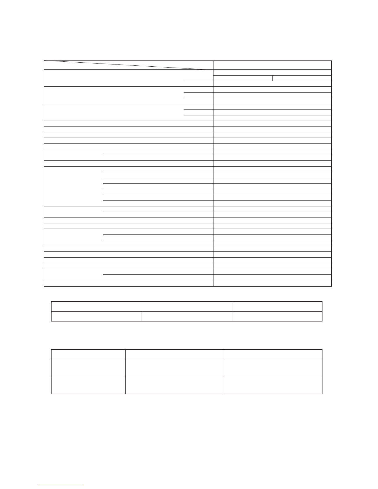
1. SPECIFICATIONS
RAV-M242A-E / RAV-M242A
2 indoor unit
AB
12, 200 x 2
6, 100
24, 400
7,1
1
220 – 240
50
2,46
99
10,8
68
53
R-22
0,95 + 0,95
Capillary tube
ø12,7 (1/2")
Flare
ø6,4 (1/4")
Flare
7,6 (25)
15 (48)
2 ( 7 )
5 (16)
5 (16)
RAS-13SK-E or RAS-13SKX
RAV-M242A-E or RAV-M242A
790 (2 – 7 1/8)
880 (2 – 9 1/8)
310 (1 – 1/4)
70 (154,3)
Finned tube
Propeller fan
63
PH160X2-4L
1,100
Fuse, inner overload-relay
Model
Item
Operation Unit
*1 BTU/h
kcal/h
Cooling capacity *1 BTU/h
kW
Phase
Power source V
Hz
Power consumption Cooling kW
Power factor Cooling %
Running current Cooling A
Starting current Cooling A
Operating noise (SPL*4) dB (A)
Refrigerant
Name of refrigerant
Charge volume kg
Refrigerant control
Gas side size mm (in.)
Coupler style
Liquid side size mm (in.)
Coupler style
Standard length m (ft)
Maximum length (One-way) *2 m (ft)
Minimum length m (ft)
Maximum height
Indoor unit higher m (ft)
Outdoor unit higher m (ft)
INDOOR UNIT MODEL
OUTDOOR UNIT MODEL
Height mm (ft-in.)
Dimensions Width mm (ft-in.)
Depth mm (ft-in.)
Net weight kg (Ibs)
Condenser type
Condenser fan type
Fan motor output W
Compressor
Model
Output W
Protective device
Condenser air inlet temperature
35°C DB (95°F DB)
Evaporator air inlet temperature
27°C DB (80°F DB) 19,0°C WB (66°F WB)
Note 1: Cooling capacity is based on the following temperature conditions.
Note 2: These mean equivalent length.
Note 3: Operating range of the units
Note 4: SPL: Sound Pressure Level
Note 5: Specifications are subject to change without notice.
Remark:
• Be sure to refer to the service manual file No. A00-9701 for the indoor unit RAS-13SKX (or RAS-13SK-E) to be
connected.
Condenser air inlet temperature
43°C DB (109°F DB)
21°C DB (70°F DB)
Evaporator air inlet temperature
32°C DB, 22,5°C WB
(95°F DB, 73°F WB)
21°C DB, 15,5°C WB
(70°F DB, 60°F WB)
Maximum
Minimum
– 4 –
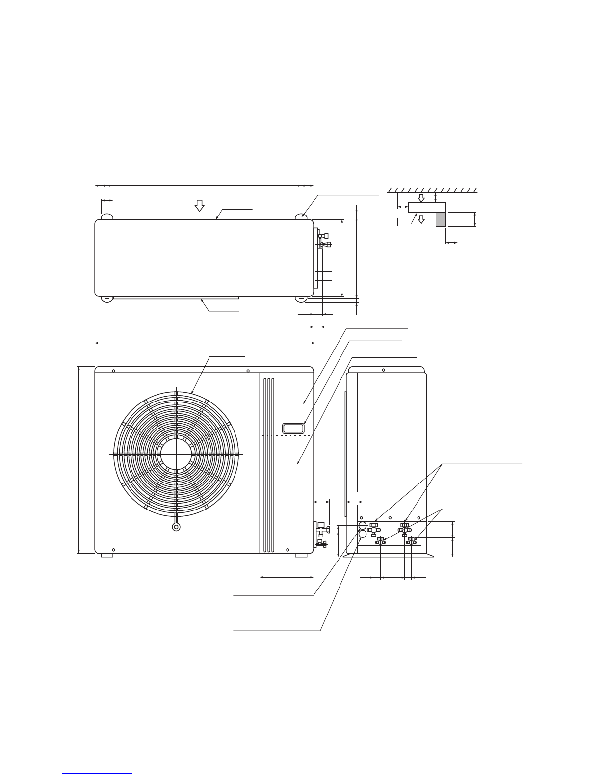
2. CONSTRUCTION VIEWS
Outdoor Unit
RAV-M242A-E (or RAV-M242A)
340 1212
310
45
36
31
79045
50
Air inlet
Air outlet
880
257
70 57
34
Refrigerant piping joint
(Gas side 2-ø12,7)
Refrigerant piping joint
(Liquid side 2-ø6,4)
3486
Power supply cord hole
(ø19 knockout hole)
Inter-unit wiring cord hole
(
ø28 knockout hole
)
65 60
107 33
790
Air outlet
Electric parts box
Carrying handle
(Both side)
Electric parts cover
100
Outlet
(Space for wiring
and piping)
100
Space required for service
Space for service
When installing, the inlet is
to be faced the wall side.
300
500
Anchor bolt hole
(4-12x18 long hole)
– 5 –
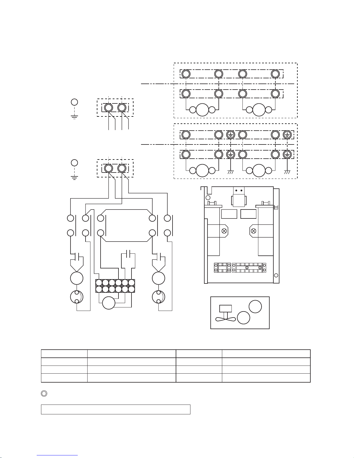
3. WIRING DIAGRAM
Shows terminal block and figures show terminal numbers.
Broken lines show wiring at site.
Don't operate the units with the magnetic contactor pushed.
Symbol Name
CM1, 2 Compressor
FMo Fan moter
RCc1, 2 Running capacitor (Compressor)
Symbol Name
RCo Running capacitor (Fan motor)
51C1, 2 Overload relay
52C1, 2 Magnetic contacto
11
L N
12
CM1
RCo1
RCo
WHI
BLK
BLK
RED
RED
51C1
52C1 52C2
220-240V 1Ph 50Hz
power supply
Outdoor Unit
Earth screw
Indoor Unit
131415
16
6
11
12
CM2
RCo2
WHI
BLK
BLK
RED
RED
51C2
13
14
A B
5 4 3 2 1
6 5 4 3 2 1
FMo
1 2 1
52C1 A B52C2
Unit A Unit B
2
1 2 1 2
A B
1 2 1
52C1
A B
52C2
Unit A Unit B
2
1 2 1 2
(Electrical Parts Box)
Parts Position
(Fan Motor, Compressor,Coil)
RCo
52C2
RCc2RCc1
52C1
NL2121
CM1
FMo
CM2
Outdoor Unit
Indoor Unit
A N
220-240V 1Ph 50Hz
power supply
Earth screw
RAV-M242A
RAV-M242A-E
– 6 –
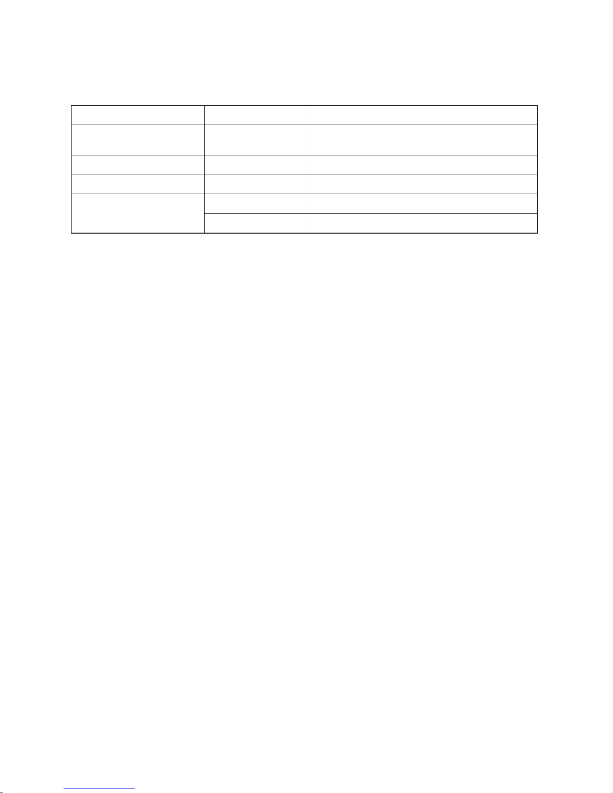
4. SPECIFICATIONS OF ELECTRICAL PARTS
Parts name Type Specifications
Compressor 1, 2
PH160X2-4L
Output 1,1 kW, 2 pole, 1 φ, 220 – 240 V, 50 Hz
Winding resistance: Main coil 2,2 Ω, Aux. coil 3,8 Ω
Fan motor STF-200-63B Output 63 W, 6 pole, 1 φ, 220 – 240 V, 50 Hz
Magnetic contactor VC20FA AC 240 V
Capacitor
MT-40MP356W For compressor 1, 2, AC 400 V, 35 µF
EAG45M355UF1 For fan motor, AC 450 V, 3,5 µF
– 7 –
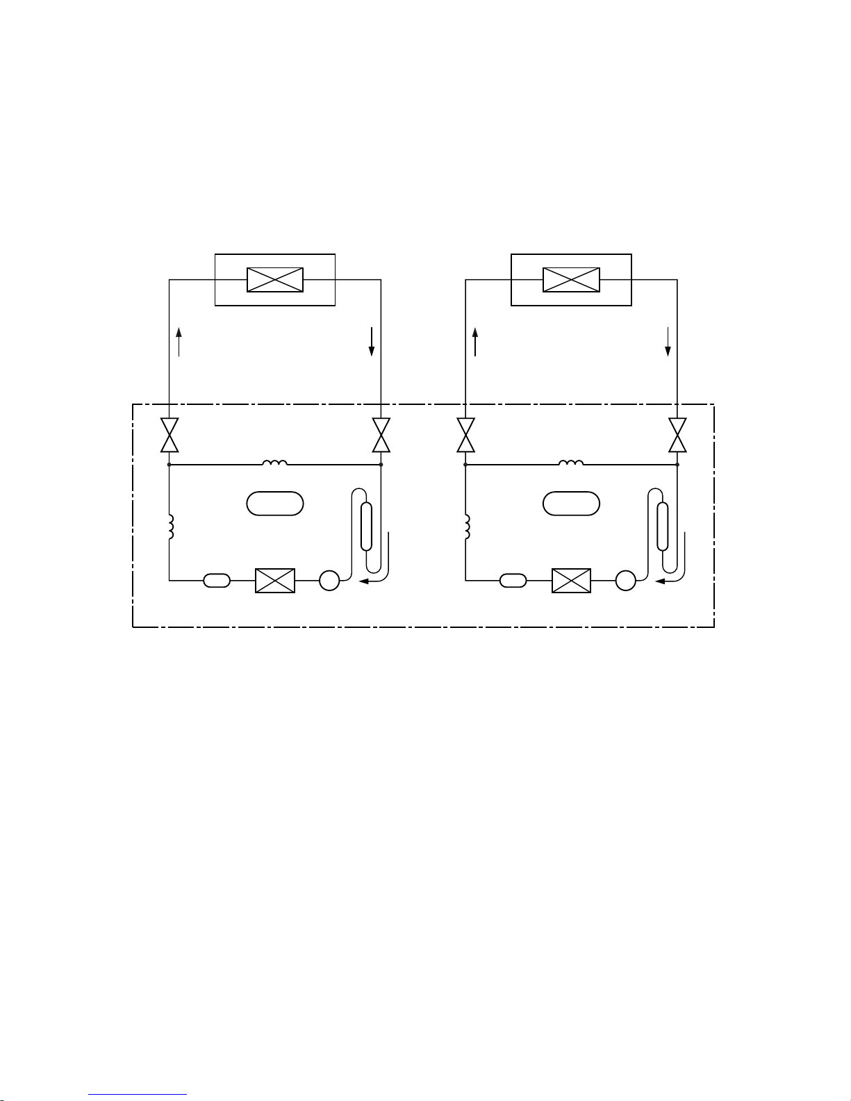
5. REFRIGERANT PIPING DIAGRAM
Evaporator
(Indoor unit A)
(RAS-13SK)
CYCLE 1
Condenser
Dryer
Compressor 1
Accumulator
Refrigerant pipe
(Liquld side)
φ6,4mm
Packed
valve
Capillary tube
φ1,7 x 600
Packed
valve
Refrigerant pipe
(Gas side)
φ12,7mm
Outdoor Unit
Capillary tube
φ0,6 x 600
Evaporator
(Indoor unit B)
(RAS-13SK)
CYCLE 2
Condenser
Dryer
Compressor 2
Accumulator
Refrigerant pipe
(Liquld side)
φ6,4mm
Packed
valve
Capillary tube
φ1,7 x 600
Packed
valve
Refrigerant pipe
(Gas side)
φ12,7mm
Capillary tube
φ0,6 x 600
– 8 –
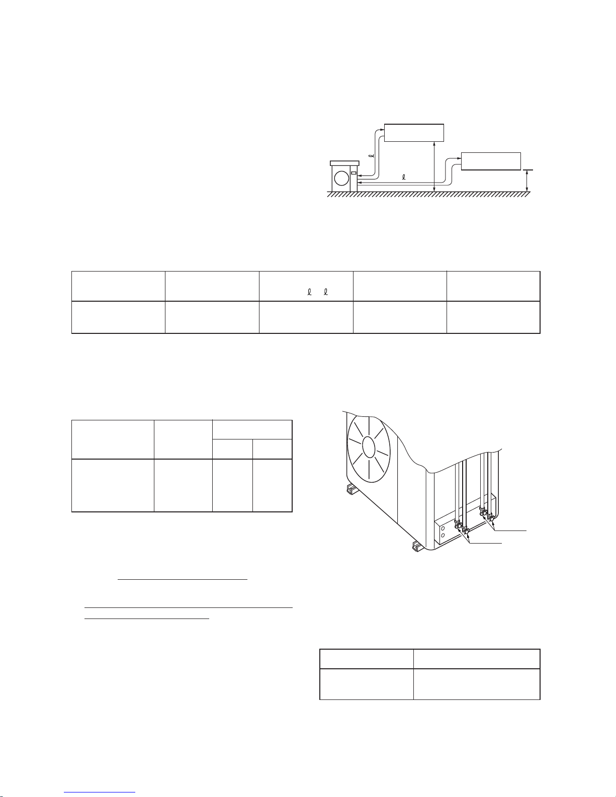
Model
Connectable indoor Permissible piping Permissible piping
Remarks
unit number length ( 1, 2) head (H)
RAS-13SK-E
2 15m 5m Fig. 5-1
(or RAS-13SKX)
5-1. Refrigerant Piping
5-1-1. Permissible Piping Length and Head
The minimum inter-unit refrigerant piping length shall
be 2m.
Limit the number of bends in the refrigerant piping to
10 or less.
Fig. 5-1
Table 5-1
5-1-2. Piping Material and Sizes
Table 5-2
Piping material
Phosphate deoxidized copper
seamless pipes for
air conditioners
Model
RAS13SK-E
(or RAS13SKX)
Piping size (mm)
Larger Smaller
12,7 6,4
5-1-3. Air Purging
• Subject the refrigerant tube of outdoor and indoor
units to air purge with a vacuum pump.
• Do not carry out this air purge by using the refrigerant filled in the outdoor unit.
• To handle valves, a 5mm hexagon wrench is
needed.
5-1-4. Refrigerant Pipe Connecting Position
H
H
Unit A
2
1
RAS-13SK-E
(or RAS-13SKX)
Unit B
RAS-13SK-E
(or RAS-13SKX)
Model Addition per meter
RAV-M242A-E
No need
(or RAV-M242A)
Fig. 5-2
5-1-5. Additional Refrigerant Quantities
Table 5-3
Unit B
Unit A
– 9 –
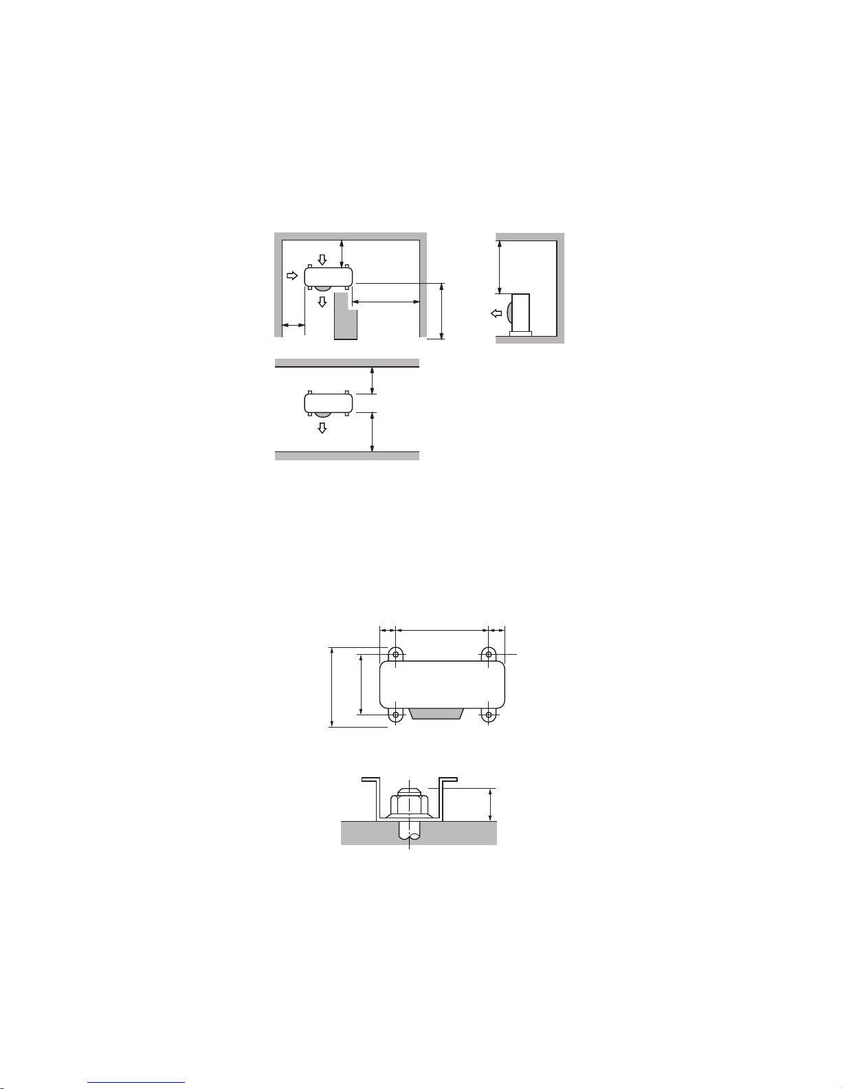
6. UNIT INSTALLATION
Service Space
Ensure that there is sufficient space around the outdoor unit for installation and servicing.
Fig. 6-1
• Do not install in a place that can increase the vibration and amplify the noise level of the units.
• Be sure to fix the outdoor unit with four (4) M10 anchor bolts according to f oundation drawings below.
45 45790
340
15
364
100 or more
500 or more
500 or more
300 or more
100 or more
500 or more
100
or more
Fig. 6-2
 Loading...