

Toshiba RAV-M240A-E Service Manual

SERVICE MANUAL
RAV-M240A-E
Unit B
Unit A
Unit D
Unit C
RAS-09EK
AIR-CONDITIONER
RAV-M240A-E
FILE NO. A10-9506
SPLIT WALL TYPE
(Combination with RAS-09EK)
PRINTED IN JAPAN Jan, 1996
S

– 2 –
CONTENTS
1. SPECIFICATIONS ............................................................................................................. 3
2. CONSTRUCTION VIEWS................................................................................................. 5
2-1. Outdoor Unit....................................................................................................................................... 5
3. WIRING DIAGRAM ........................................................................................................... 6
4. SPECIFICATIONS OF ELECTRICAL PARTS ................................................................... 8
5. REFRIGERANT PIPING DIAGRAM.................................................................................. 9
5-1. Refrigerant Piping ............................................................................................................................ 10
6. UNIT INSTALLATION ....................................................................................................... 11
6-1. Service Space ...................................................................................................................................11
7. OPERATIONAL MATRIX OF ELECTRICAL PARTS ....................................................... 12
8. TROUBLESHOOTING CHART FOR RAS-09EK/RAV-M240A-E .................................... 14
8-1. What to be Prechecked First............................................................................................................ 14
8-2. Primary Judgement of Trouble Sources ....................................................................................... .... 15
8-3. Troubleshooting Flowcharts ................................................................................................. ............ 19
8-4. Test Points on the PC Board and List of Voltage Values .................................................................. 21
8-5. How to Check the Remote Control (Including the Indoor PC Board) ............................................... 22
8-6. PC Board Layout.............................................................................................................................. 25
9. EXPLODED VIEWS AND PARTS LIST ........................................................................... 26
– 3 –
RAV-M240A-E
1
220-240
50
53
R-22
0.9 + 0.9
Capillary tube
9.5 (3/8”)
Flare
6.4 (1/4”)
Flare
7.6 (25)
A + B < 15m, A – B < 8m
A or B < 10m
2 (7)
5 (16)
5 (16)
RAS-09EK, SERVICE D ATA FILE NO. A00-9507
RAV-M240A-E
790 (2’7-7/64”)
880 (34.64”)
310 (12.2”)
70 (154.3)
Finned tube
Propeller fan
63
PH160X2-4L
1100
Fuse
Inner overload relay
Model
Unit
BTU/h
kcal/h
BTU/h
kW
Phase
V
Hz
kW
%
A
A
dB (A)
kg
mm (in.)
mm (in.)
m (ft)
m (ft)
m (ft)
m (ft)
m (ft)
mm (ft-in.)
mm (ft-in.)
mm (ft-in.)
kg (lbs)
W
W
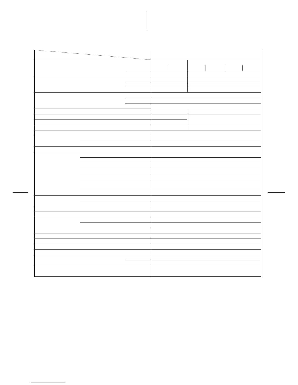
Item
Operation
Cooling capacity
Power source
Power consumption
Power factor
Running current
Starting current
Operating noise (SPL)
Refrigerant
Refrigerant control
Interconnection pipe
Maximum height
INDOOR UNIT Model
OUTDOOR UNIT Model
Dimensions
Net weight
Condenser type
Condenser fan type
Fan motor output
Compressor
Protective device
Cooling
Cooling
Cooling
Cooling
Name of refrigerant
Charge volume
Gas side size
Coupler style
Liquid side size
Coupler style
Standard length
Maximum length
(of one way)
Minimum length
Indoor unit higher
outdoor unit higher
Height
Width
Depth
Model
Output
*2
*1
*1
A or B C or D A B C D
12000
6000
24000
7.0
6000
6000
24000
7.0
1.86
97.4
8.3
58
2.45
97
11.0
2 indoor unit
4 indoor unit
1. SPECIFICATIONS
Specifications are subject to change without notice.

– 4 –
Note 2:
• These mean equivalent length.
Note 3:
• Operating range of the units
Evaporator air inlet temperature
Condenser air inlet temperature
27°C DB (80°F DB)
19.5°C WB (67°F WB)
35°C DB (95°F DB)
Maximum
Minimum
Condenser air inlet temperature
43°C DB (109°F DB)
21°C DB (70°F DB)
Evaporator air inlet temperature
32°C DB, 22.5°C WB
(95°F DB, 73°F WB)
21°C DB, 15.5°C WB
(70°F DB, 60°F WB)
Remark:
• Be sure to refer to the service manual file No. A00-9507 for the indoor unit RAS-09EK to be connected.
Note 1:
• Cooling capacity is based on the following temperature conditions. [Condition A]

– 5 –
2. CONSTRUCTION VIEWS
2-1. Outdoor Unit
RAV-M240A-E
Fig. 2-1
880
Air outlet
Air outlet
36
31
12
340
310
12
Anchor bolt hole
(4-12
X18 long hole)
Space required for service
Space for service
500
300
Outlet
100
(Space for wiring
and piping)
When installing,the inlet is
to be faced to the wall side.
Electric parts box
Carrying handle
Electric parts cover
(Both side)
Refrigerant piping joint
(Gas side 2-Φ9.5)
Refrigerant piping joint
(Liquid side 4-Φ6.5)
60
65
70 57
33
107
34 34 52 34 34
257
Power supply cord hole
(Φ19 knockout hole)
Inter-unit wiring cord hole
(Φ 28 knockout hole)
790
Air inlet
790 4545
50
100

– 6 –
3. WIRING DIAGRAM
Fig. 3-1
Shows terminal block and figures show terminal numbers.
Broken lines show wiring at site.
Don’t operate the units with the magnetic contactor pushed.
2
2
1
1
43B27
8
20SRB
2
BLU
BLK
BLU
2
2
1
1
43A2
78
20SRA
2
BLU
BLK
BLU
REDRED
GRN GRN
Unit C Unit D
2
2
1
1
43B1
78
20SRB
1
BLU
BLK
BLU
2
2
1
1
43A1
78
20SRA
1
BLU
BLK
BLU
REDRED
GRN GRN
2
4
6
2
4
6
43A2
43B2
2
5
8
43C2
1
3
5
43A2
1
4
7
43C2
3
6
9
43C2
L
H
C
23L2
A
B
52C
2
20SRD
2
20SRC
2
1
3
5
T2
23H2
1
2
43C
2
T2
103
411
BRW
BRW
BRW
BRW
BRW
BLU
BLU
BLU
PUR
BLU
BLU
SKB
BLU
BLU
BLUBLU
BLU
2
4
6
2
4
6
43A1
2
8
1
3
5
43A1
1
4
7
43C1
3
6
9
L
H
C
A
B
52C
1
20SRD
1
20SRC
1
1
3
5
1
2
43C
1
T1
103
411
RED
SKB
BLU
BLU
SKB
BLU
BLU
BLK
13
NL
14
52C2
11
12
15
16
65432
1
65432
1
13
14
RED
RED
FMo
CM2
RED
RCo2
RED
WHI
F
WHI
GRY
RED
BLK
RC0
CM
1
RED
RCo1
RED
WHI
F
RED
11
12
BLK
RED
BLK
BLK
BLK
51C2
BLK
51C1
52C1
Earth
43C1 43B1
PNK
RED
RED
RED
RED
43B2
43C123L1
T1
23H1
43B1
YEL
YEL
SKB
SKB
Unit A Unit B
Power Supply
220-240V 1Ph 50Hz
Outdoor Unit
Indoor Unit
RED
BLK BLK
BLK BLK
PNK
PNK
ORN
ORN ORN ORN
ORN
PN
K
PNK
5

– 7 –
12 12 LN 12 12
RCc1
T1
43A1
43B1 43A2
43B2
T2
23L1
43C243C1
RCc2
52C1 52C2
RCc
23L2
20SRD2
20SRD2
20SRD1
20SRC1
CM1
CM2
20SRB2
20SRA2
20SRB1
20SRA1
FM
Fig. 3-2
Table 3-1
Symbol
CM1, 2
FMo
RCc1, 2
RCo
51C1, 2
52C1, 2
43A1, 2
43B1, 2
43C1, 2
20SRA1, 2
20SRB1, 2
20SRC1, 2
20SRD1, 2
T1, 2
23L1, 2
Name
Compressor
Fan motor
Running capacitor (Compressor)
Running capacitor (Fan motor)
Overload relay
Magnetic contactor
Relay
Relay
Solenoid coil
Thermal timer
Thermostat
Model name
PH160X2-4L
STF-200-63B
MT-40MP356W
EAG45M355UF1
MRA99420
VC20FA 3P AC240V
LY2F-AC220-240V
LY3F-AC220-240V
NEVAC240V
230-B-180-4BFP
ATB-T306

– 8 –
4. SPECIFICATIONS OF ELECTRICAL PARTS
Parts name
Compressor 1, 2
Fan motor
Magnetic contactor
Capacitor
Solenoid coil (2-way valve)
Relay
Thermal timer
Type
PH160X2-4L
STF-200-63B
VC20FA
MT-40MP356W
EAG45M355UF1
NEV AC240
LY2F
LY3F
230-B-180-4BFP
Specifications
Output 1.1 kW, 2 pole, 1ø, 220-240V, 50 Hz
Winding resistance: Main coil 2.2Ω, Aux. coil 3.5Ω
Output 63W, 6 pole, 1ø, 220-240V, 50 Hz
AC 240V
For compressor 1, 2: PH160X2-4L, AC 400V, 35 µF
For fan motor, AC 450V, 3.5 µF
AC 220-240V
Coil 220-240V, 50/60 Hz
Coil 220-240V, 50/60 Hz
AC 220-240V, 3-min. (Delay)

– 9 –
5. REFRIGERANT PIPING DIAGRAM
RAV-M240A-E
Fig. 5-1
(indoor unit B)
(Indoor unit A)
(RAS-09EK)
Evaporator
Evaportator
(RAS-09EK)
Refrigerant pipe
(Gas slde)
φ
9.5mm
Packed valvex2
Two way valvex2
20SRA1
20SRB1
Capillary
φ
2 x 800 x2
Capillary
φ
1.7 x 600
Two way valve
Dryer
Condenser
Compressor1
20SRD1
Accumulator
Packed valve
CYCLE 1
20SRCI
(Indoor unit C)
Evaporator
(Indoor unit D)
Evaporator
(RAS-09EK)
(RAS-09EK)
Packed valve x 2
Two way valve x2
20SRA2
20SRB2
Two way valve
20SRC2
Dryer
Condenser
Compressor2
20SRD2
Accumulator
Packed valve
CYCLE 2
Refrigerant pipe
(Liquld side)
φ
6.4mm
Capillary tube
φ
1.7 x 600
Outdoor
Unit
φ
2 x 300
Capillary
φ
2x 300
Capillary
Refrigerant pipe
(Liquld side)
φ
6.4mm
Refrigerant pipe
(Gas slde)
φ
9.5mm
Capillary
φ
2 x 800 x2
 Loading...