

Toshiba RAV-GM301ATP-E, RAV-GM401ATP-E, RAV-GM401ATP-ETR, RAV-GM301ATJP-E, RAV-GM301ATP-ETR Service Manual

SERVICE MANUAL
OUTDOOR UNIT
<DIGITAL INVERTER>
RAV-GM301ATP-E (TR)
RAV-GM401ATP-E (TR)
RAV-GM301ATJP-E
RAV-GM401ATJP-E
AIR-CONDITIONER
(SPLIT TYPE)
FILE NO. SVM-18042-1
R32
Revised on June, 2018

– 2 –
Original instruction
Adoption of Refrigerant
To prevent the ozone layer destruction, this air conditioner adopted refrigerant R32
instead the conventional refrigerant R22.
CONTENTS
SAFETY CAUTION ....................................................................................................... 3
1.
SPECIFICATIONS ..........................................................................................................17
1-
1. Outdoor Unit ........................................................................................................................................17
1-
2. Operation Characteristic Curve .......................................................................................................... 18
2.
CONSTRUCTION VIEWS (EXTERNAL VIEWS) ...........................................................20
2-
1. RAV-GM301AT*P*, RAV-GM401AT*P* .............................................................................................20
3.
SYSTEMATIC REFRIGERATING CYCLE DIAGRAM ...................................................21
3-
1. Outdoor Unit .........................................................................................................................................21
3-
2. Operation Data......................................................................................................................................23
4.
WIRING DIAGRAM ........................................................................................................24
4-
1. RAV-GM301AT*P* ..............................................................................................................................24
5.
SPECIFICATIONS OF ELECTRICAL PARTS ...............................................................25
6.
REFRIGERANT R32 .......................................................................................................26
6-
1. Safety During Installation/Servicing .................................................................................................... 26
6-
2. Refrigerant Piping Installation ............................................................................................................. 26
6-
3. Tools ....................................................................................................................................................30
6-
4. Recharging of Refrigerant ...................................................................................................................30
6-
5. Brazing of Pipes ..................................................................................................................................31
6-
6. Instructions for Re-use Piping of R22 or R407C .................................................................................33
6-
7. Replenishing refrigerant ......................................................................................................................36
7.
OUTDOOR CONTROL CIRCUIT ...................................................................................37
7-
1. Outline of Main Controls ......................................................................................................................37
7-
2. Outdoor Print Circuit Board .................................................................................................................43
8.
TROUBLESHOOTING ...................................................................................................44
8-
1. Summary of Troubleshooting ..............................................................................................................44
8-
2. Troubleshooting ...................................................................................................................................46
8-
3. Table Inspection of outdoor unit main parts .........................................................................................63
9.
SETUP AT LOCAL SITE AND OTHERS .......................................................................64
9-
1. Calling of Error History .........................................................................................................................64
9-
2. Group Control Operation ......................................................................................................................64
10.
ADDRESS SETUP .........................................................................................................66
10-
1. Address Setup Procedure ..................................................................................................................66
10-
2. Address Setup & Group Control .........................................................................................................67
10-
3. Remote Controller Wiring ...................................................................................................................70
10-
4. Address Setup (Manual setting from remote controller) .....................................................................70
10-
5. Confirmation of Indoor Unit No. Position ............................................................................................71
11.
HOW TO EXCHANGE COMPRESSOR .........................................................................73
11-1. Exchanging Procedure of Compressor (Outline)................................................................................73
11-2. Exchange of Compressor.................................................................................................................. 73
12.
DETACHMENTS ............................................................................................................74
12-
1. RAV-GM301AT*P*, RAV-GM401AT*P* ...........................................................................................74
13.
EXPLODED VIEWS AND PARTS LIST .........................................................................82
4-
2. RAV-GM401AT*P* ..............................................................................................................................24
13-1. RAV-GM301ATP-E, RAV-GM301ATP-TR ........................................................................................82
13-3. RAV-GM401ATP-E, RAV-GM401ATP-TR ........................................................................................90
13-2. RAV-GM301ATJP-E ......................................................................................................................... 86
13-4. RAV-GM401ATJP-E ......................................................................................................................... 94
FILE NO. SVM-18042
– 3 –
Agent
Qualified
installer (∗1)
Qualified service
person (∗1)
Qualifications and knowledge which the agent must have
The qualified installer is a person who installs, maintains, relocates and removes the air
conditioners made by Toshiba Carrier Corporation.
He or she has been trained to install, maintain, relocate and remove the air conditioners made by
Toshiba Carrier Corporation or, alternatively, he or she has been instructed in such operations by
an individual or individuals who have been trained and is thus thoroughly acquainted with the
knowledge related to these operations.
The qualified installer
who is allowed to do the electrical work involved in installation, relocation
and removal has the qualifications pertaining to this electrical work as stipulated by the local laws
and regulations, and he or she is a person who has been trained in matters relating to electrical
work on the air conditioners made by Toshiba Carrier Corporation or, alternatively, he or she has
been instructed in such matters by an individual or individuals who have been trained and is thus
thoroughly acquainted with the knowledge related to this work.
The qualified installer who is allowed to do the refrigerant handling and piping work involved in
installation, relocation and removal has the qualifications pertaining to this refrigerant handling
and piping work as stipulated by the local laws and regulations, and he or she is a person who
has been trained in matters relating to refrigerant handling and piping work on the air conditioners
made by Toshiba Carrier Corporation or, alternatively, he or she has been instructed in such
matters by an individual or individuals who have been trained and is thus thoroughly acquainted
with the knowledge related to this work.
The qualified installer who is allowed to work at heights has been trained in matters relating to
working at heights with the air conditioners made by Toshiba Carrier Corporation or, alternatively,
he or she has been instructed in such matters by an individual or individuals who have been
trained and is thus thoroughly acquainted with the knowledge related to this work.
The qualified service person is a person who installs, repairs, maintains, relocates and removes
the air conditioners made by Toshiba Carrier Corporation. He or she has been trained to install,
repair, maintain, relocate and remove the air conditioners made by Toshiba Carrier Corporation or,
alternatively, he or she has been instructed in such operations by an individual or individuals who
have been trained and is thus thoroughly acquainted with the knowledge related to these operations.
The qualified service person who is allowed to do the electrical work involved in installation,
repair, relocation and removal has the qualifications pertaining to this electrical work as stipulated
by the local laws and regulations, and he or she is a person who has been trained in matters
relating to electrical work on the air conditioners made by Toshiba Carrier Corporation or,
alternatively, he or she has been instructed in such matters by an individual or individuals who
have been trained and is thus thoroughly acquainted with the knowledge related to this work.
The qualified service person who is allowed to do the refrigerant handling and piping work
involved in installation, repair, relocation and removal has the qualifications pertaining to this
refrigerant handling
and piping work as stipulated by the local laws and regulations, and he or
she is a person who has been trained in matters relating to refrigerant handling and piping
work on the air conditioners made by Toshiba Carrier Corporation or, alternatively, he or she
has been instructed in such matters by an individual or individuals who have been trained
and is thus thoroughly acquainted with the knowledge related to this work.
The qualified service person who is allowed to work at heights has been trained in matters
relating to working at heights with the air conditioners made by Toshiba Carrier Corporation or,
alternatively, he or she has been instructed in such matters by an individual or individuals who
have been trained and is thus thoroughly acquainted with the knowledge related to this work.
SAFETY CAUTION
Please read carefully through these instructions that contain important information which complies with the
Machinery Directive (Directive 2006/42/EC), and ensure that you understand them.
Some of the details provided in these instructions differ from the service manual ,and the instruction provided
here take precedence.
Generic Denomination: Air Conditioner
Definition of Qualified Installer or Qualified Service Person
The air conditioner must be installed, maintained, repaired and removed by a qualified installer or qualified
service person.
When any of these jobs is to be done, ask a qualified installer or qualified service person to do them for you.
A qualified installer or qualified service person is an agent who has the qualifications and knowledge
described in the table below.
FILE NO. SVM-18042
•
•
•
•
•
•
•
•
– 4 –
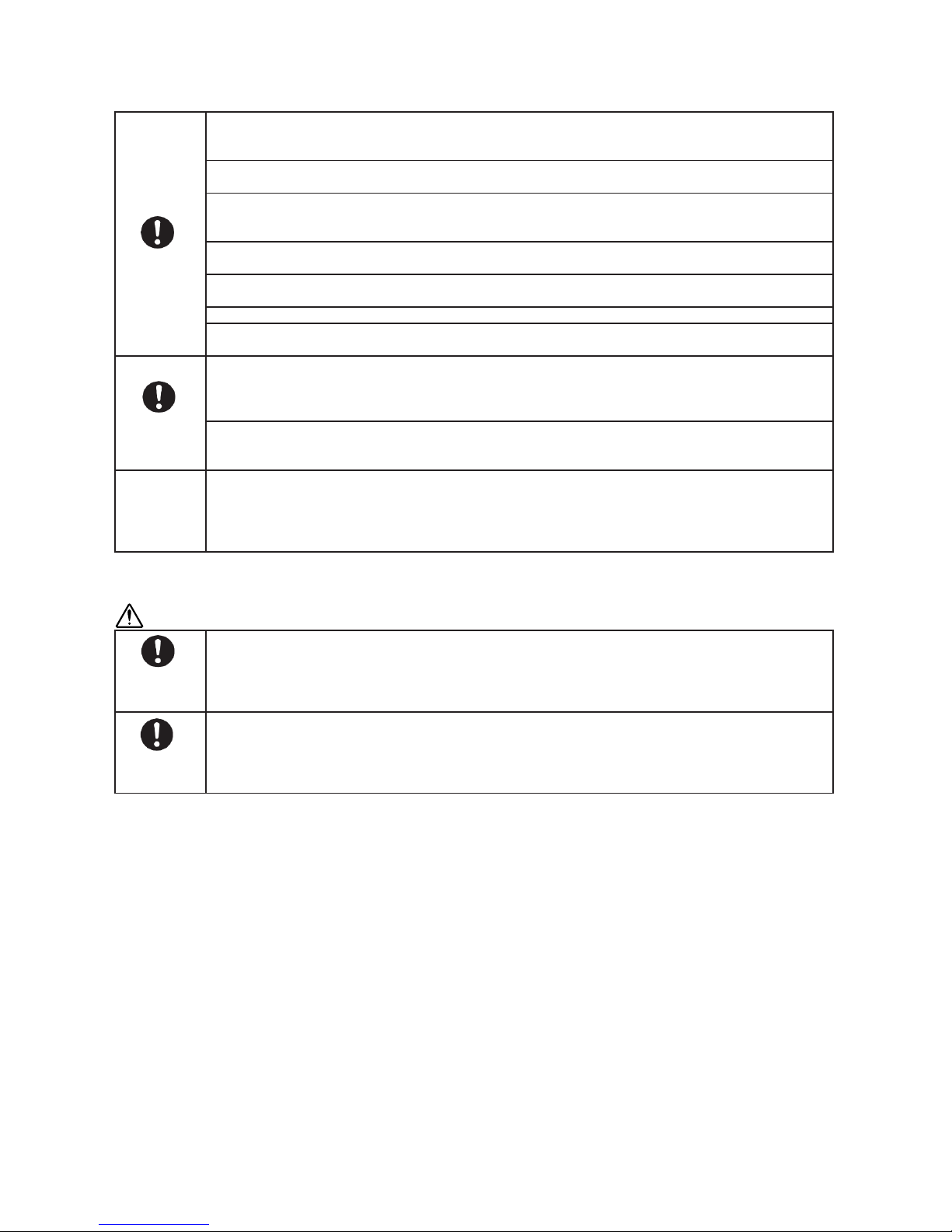
Definition of Protective Gear
When the air conditioner is to be transported, installed, maintained, repaired or removed, wear protective
gloves and “safety” work clothing.
In addition to such normal protective gear, wear the protective gear described below when undertaking the
special work detailed in the table below.
Failure to wear the proper protective gear is dangerous because you will be more susceptible to injury, burns,
electric shocks and other injuries.
Work undertaken
All types of work
Electrical-related work
Work done at heights (50 cm or more)
Transportation of heavy objects
Repair of outdoor unit
Protective gear worn
Protective gloves
“Safety” working clothing
Gloves to provide protection for electricians
Insulating shoes
Clothing to provide protection from electric shock
Helmets for use in industry
Shoes with additional protective toe cap
Gloves to provide protection for electricians
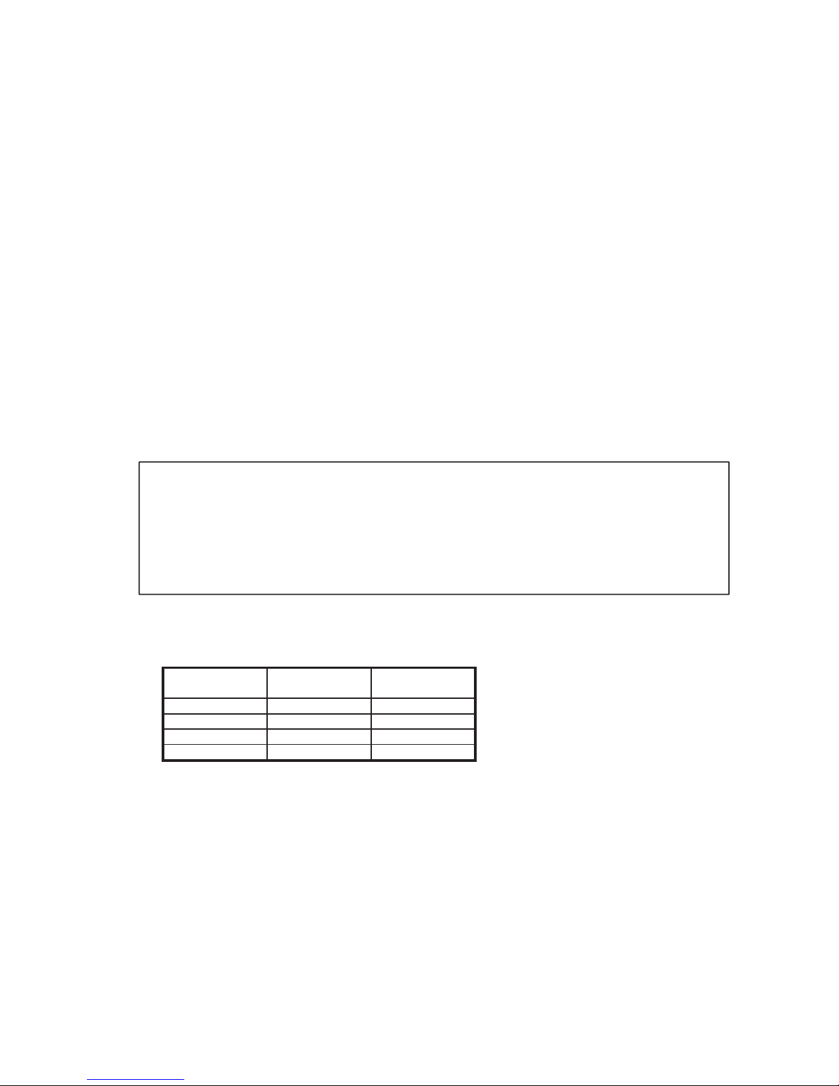
The important contents concerned to the safety are described on the product itself and on this Service Manual.
Please read this Service Manual after understanding the described items thoroughly in the following contents
(Indications/Illustrated marks), and keep them.
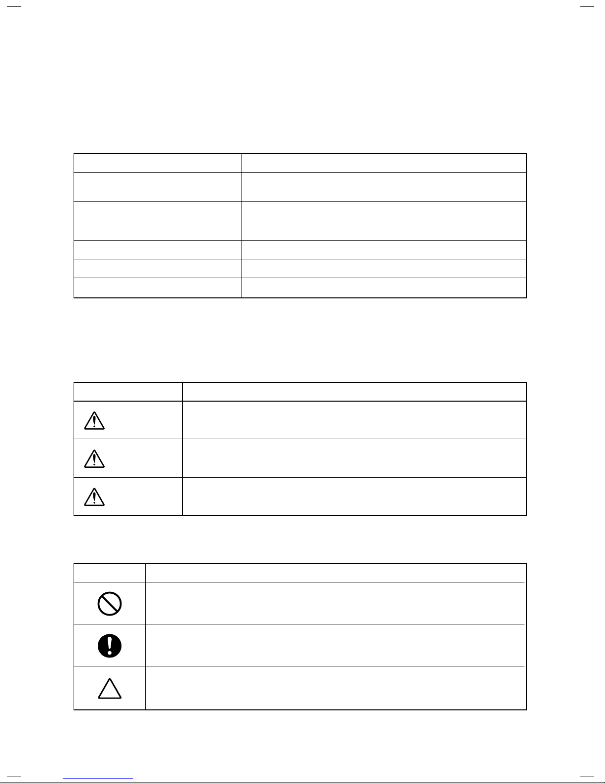
[Explanation of indications]
Indication
DANGER
WARNING
CAUTION
Explanation
Indicates contents assumed that an imminent danger causing a death or serious injury of
the repair engineers and the third parties when an incorrect work has been executed.
Indicates possibilities assumed that a danger causing a death or serious injury of the
repair engineers, the third parties, and the users due to troubles of the product after work
when an incorrect work has been executed.
Indicates contents assumed that an injury or property damage (∗) may be caused on the
repair engineers, the third parties, and the users due to troubles of the product after work
when an incorrect work has been executed.
∗ Property damage : Enlarged damage concerned to property, furniture, and domestic animal/pet
[Explanation of illustrated marks]
Mark Explanation
Indicates prohibited items (Forbidden items to do)
The sentences near an illustrated mark describe the concrete prohibited contents.
Indicates mandatory items (Compulsory items to do)
The sentences near an illustrated mark describe the concrete mandatory contents.
Indicates cautions (Including danger/warning)
The sentences or illustration near or in an illustrated mark describe the concrete cautious contents.
FILE NO. SVM-18042
– 5 –
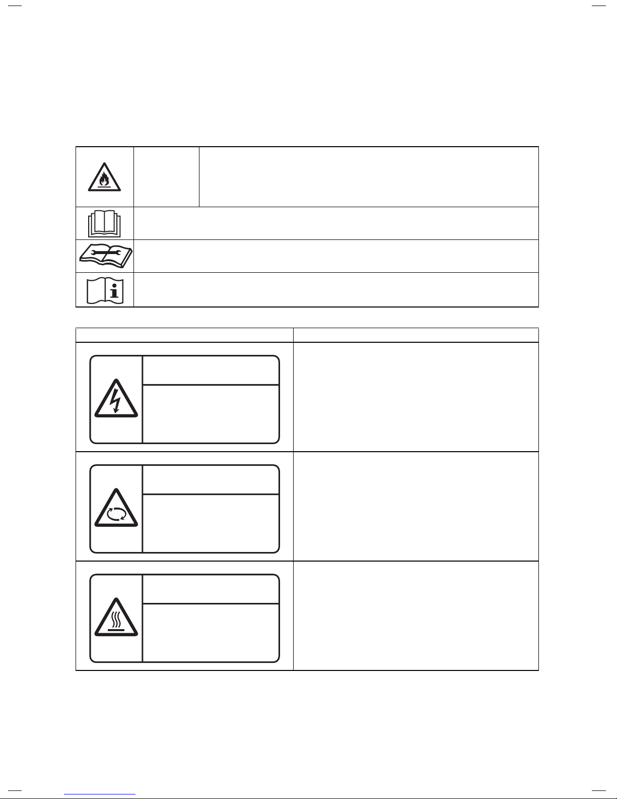
WARNING
(Risk of fire)
This mark
is for
R32 refrigerant only.
Refrigerant type
is
written on nameplate
of
outdoor
unit.
In
case that
refrigerant type
is
R32,
this
uni
t uses
a flammable refrigerant.
If refriger
ant l
eaks an
d comes
in contac
t with
fire
or heating part, it
will
create
harmful
gas and
there
is risk
of fire.
Read the OWNER’S MANUAL carefully befor
e operation.
Se
rvice personnel are required
to
carefully read
the
OWNER’S MANUAL and INSTALLATION
MANUAL befo
re operation.
Further inform
ation is available in the OWNER’S MANUAL, INSTALLATION MANUAL, and the like.
Warning indication Description
WARNING
ELECTRICAL SHOCK HAZARD
Disconnect
all remote electric power
supplies before servicing.
WARNING
Moving parts.
Do not operate unit with grille removed. Stop the
unit before the servicing.
CAUTION
High temperature parts.
You might get burned when removing this panel.
WARNING
ELECTRICAL SHOCK HAZARD
Disconnect all remote electric
power supplies before ser
vicing.
WARNING
Moving parts.
Do not operate unit with grille removed.
Stop the unit before the servicing.
CAUTION
High temperature parts.
Y
ou might get burned
when removing this panel.
Warning Indications on the Air Conditioner Unit
[Confirmation of warning label on the main unit]
Confirm that labels are indicated on the specified positions
If removing the label during parts replace, stick it as the original.
FILE NO. SVM-18042
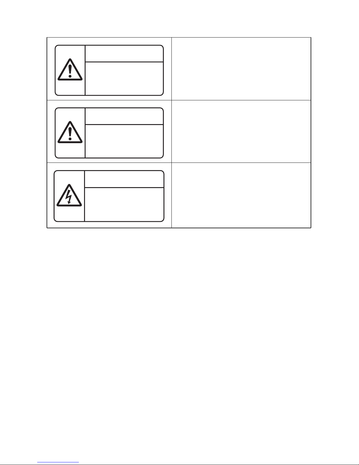
CAUTION
Do not touch the aluminum fins of the
unit. Doing so may result in injury.
CAUTION
BURST HAZARD
Open the service valves before the operation,
otherwise there might be the burst.
CAUTION
Do not touch the aluminum fins
of the unit.
Doing so may result in injury.
CAUTION
BURST HAZARD
Open the service valves before
the operation, otherwise there
might be the burst.
Capacitor connected within
this disconnect or
downstream upon shutdown
wait 5 minutes to allow
capacitors to discharge.
WARNING
WARNING
Open the service valves before the operation,
otherwise there might be the burst.
FILE NO. SVM-18042
– 6 –
– 7 –
Before carrying out the installation, maintenance, repair or removal work, be sure to set the circuit
breaker to the OFF position. Otherwise, electric shocks may result.
Before opening the intake grille of the indoor unit or service panel or valve cover of the outdoor unit,
set the circuit breaker to the OFF position.
Failure to set the circuit breaker to the OFF position may result in electric shocks through contact with
the interior parts.
Only a qualified installer (
1) or qualified service person (1) is allowed to remove the intake grille of
the indoor unit or service panel of the outdoor unit and do the work required.
Before starting to repair the outdoor unit fan or fan guard, be absolutely sure to set the circuit breaker
to the OFF position, and place a “Work in progress” sign on the circuit breaker before proceeding with
the work.
When cleaning the filter or other parts of the indoor unit, set the circuit breaker to OFF without fail, and
place a “Work in progress” sign near the circuit breaker before proceeding with the work.
DANGER
Tu r n o ff
breaker.
Prohibition
WARNING
Before starting to repair the air conditioner, read carefully through the Service Manual, and repair
the air conditioner by following its instructions.
Only qualified service person (∗1) is allowed to repair the air conditioner. Repair of the air
conditioner by unqualified person may give rise to a fire, electric shocks, injury, water leaks
and/or other problems.
Only a qualified installer (∗1) or qualified service person (∗1) is allowed to carry out the electrical
work of the air conditioner. Under no circumstances must this work be done by an unqualified
individual since failure to carry out the work properly may result in electric shocks and/or
electrical leaks.
Wear protective gloves and safety work clothing during installation, servicing and removal.
When connecting the electrical wires, repairing the electrical parts or undertaking other electrical
jobs, wear gloves to provide protection for electricians, insulating shoes and clothing to provide
protection from electric shocks. Failure to wear this protective gear may result in electric shocks.
Use wiring that meets the specifications in the Installation Manual and the stipulations in the local
regulations and laws. Use of wiring which does not meet the specifications may give rise to
electric shocks, electrical leakage, smoking and/or a fire.
Only a qualified installer (∗1) or qualified service person (∗1) is allowed to undertake work at
heights using a stand of 50 cm or more.
When working at heights, use a ladder which complies with the ISO 14122 standard, and follow
the procedure in the ladder’s instructions. Also wear a helmet for use in industry as protective
gear to undertake the work.
When working at heights, put a sign in place so that no-one will approach the work location,
before proceeding with the work. Parts and other objects may fall from above, possibly injuring
a person below.
Do not touch the aluminum fin of the outdoor unit. You may injure yourself if you do so.
If the fin must be touched for some reason, first put on protective gloves and safety work
clothing, and then proceed.
Do not climb onto or place objects on top of the outdoor unit.
You may fall or the objects may fall off of the outdoor unit and result in injury.
When transporting the air conditioner, wear shoes with additional protective toe caps.
When transporting the air conditioner, do not take hold of the bands around the packing carton.
You may injure yourself if the bands should break.
This air conditioner has passed the pressure test as specified in IEC 60335-2-40 Annex EE.
General
FILE NO. SVM-18042
Precaution for Safety
The appliance shall be installed in accordance with national wiring regulations. Capacity shortages of the
power circuit or an incomplete installation may cause an electric shock or fire.
Do not turn ON the circuit breaker under the condition of removing a cabinet, a panel, etc.
Otherwise, it leads to an electric shock with a high voltage, resulting in loss of life.
– 8 –
When you access inside of the electric cover to repair electric parts, wait for about five minutes
after turning off the breaker. Do not start repairing immediately. Otherwise you may get electric
shock by touching terminals of high-voltage capacitors. Natural discharge of the capacitor takes
about five minutes.
Place a “Work in progress” sign near the circuit breaker while the installation, maintenance, repair
or removal work is being carried out. There is a danger of electric shocks if the circuit breaker is
set to ON by mistake.
When checking the electric parts, removing the cover of the electric parts box of Indoor Unit and/
or front panel of Outdoor Unit inevitably to determine the failure, put a sign “Do not enter” around
the site before the work. Failure to do this may result in third person getting electric shock.
Before operating the air conditioner after having completed the work, check that the electrical
parts box cover of the indoor unit and service panel of the outdoor unit are closed, and set the
circuit breaker to the ON position. You may receive an electric shock if the power is turned on
without first conducting these checks.
If, in the course of carrying out repairs, it becomes absolutely necessary to check out the
electrical parts with the electrical parts box cover of one or more of the indoor units and the
service panel of the outdoor unit removed in order to find out exactly where the trouble lies, wear
insulated heat-resistant gloves, insulated boots and insulated work overalls, and take care to
avoid touching any live parts. You may receive an electric shock if you fail to heed this warning.
Only qualified service person (䌫1) is allowed to do this kind of work.
Before troubleshooting or repair work, check the earth wire is connected to the earth terminals of
the main unit, otherwise an electric shock is caused when a leak occurs. If the earth wire is not
correctly connected, contact an electric engineer for rework.
After completing the repair or relocation work, check that the ground wires are connected properly.
Be sure to connect earth wire. (Grounding work
) Incomplete grounding causes an electric shock.
Do not connect ground wires to gas pipes, water pipes, and lightning rods or ground wires for
telephone wires.
Do not modify the products. Do not also disassemble or modify the parts.
It may cause a fire, electric shock or injury.
When any of the electrical parts are to be replaced, ensure that the replacement parts satisfy the
specifications given in the Service Manual (or use the parts contained on the parts list in the
Service Manual). Use of any parts which do not satisfy the required specifications may give
rise to electric shocks, smoking and/or a fire.
Replace components only with parts specified by the manufacturer. Other parts may result
in the ignition of refrigerant in the atmosphere from a leak.
If, in the course of carrying out repairs, it becomes absolutely necessary to check out the
electrical parts with the electrical parts box cover of one or more of the indoor units and the
service panel of the outdoor unit removed in order to find out exactly where the trouble lies, place
Keep out signs around the work site before proceeding. Third-party individuals may enter the
work site and receive electric shocks if this warning is not heeded.
Connect the cut-off lead wires with crimp contact, etc., put the closed end side upward and then
apply a water-cut method, otherwise a leak or production of fire is caused at the users’ side.
Electric
shock
hazard
Prohibition
Use
specified
parts.
Stay on
protection
Check
earth
wires.
Prohibition of
modification.
Do not bring
a child close
to the
equipment.
Insulating
measures
FILE NO. SVM-18042
– 9 –
When performing repairs using a gas burner, replace the refrigerant with nitrogen gas because
the oil that coats the pipes may otherwise burn.
When repairing the refrigerating cycle, take the following measures.
1) Be attentive to fire around the cycle.
When using a gas stove, etc., be sure to put out fire before work; otherwise the oil mixed with
refrigerant gas may catch fire.
2) Do not use a welder in the closed room.
When using it without ventilation, carbon monoxide poisoning may be caused.
3) Do not bring inflammables close to the refrigerant cycle, otherwise fire of the welder may catch
the inflammables.
The refrigerant used by this air conditioner is the R32.
Check the used refrigerant name and use tools and materials of the parts which match with it.
For the products which use R32 refrigerant, the refrigerant name is indicated at a position on
the outdoor unit where is easy to see. To prevent miss-charging, the route of the service port
is changed from one of the former R22.
Be careful for miss-charging since a chargingport of R32 is the same diameter as that of R410A.
Do not use any refrigerant different from the one specified for complement or replacement.
Otherwise, abnormally high pressure may be generated in the refrigeration cycle, which may
result in a failure or explosion of the product or an injury to your body.
For an air conditioner which uses R32, never use other refrigerant than R32.
For an air conditioner which uses other refrigerant (R22, R410A etc.), never use R32.
If different types of refrigerant are mixed, abnormal high pressure generates in the refrigerating
cycle and an injury due to breakage may be caused.
If the different type of refrigerants are mixed in, be sure to recharge the refrigerant
Do not charge refrigerant additionally.
If charging refrigerant additionally when refrigerant gas leaks, the refrigerant composition in the
refrigerating cycle changes resulted in change of air conditioner characteristics or refrigerant over
the specified standard amount is charged and an abnormal high pressure is applied to the inside
of the refrigerating cycle resulted in cause of breakage or injury. Therefore if the refrigerant gas
leaks, recover the refrigerant in the air conditioner, execute vacuuming, and then newly recharge
the specified amount of liquid refrigerant. In this time, never charge the refrigerant over the
specified amount.
When recharging the refrigerant in the refrigerating cycle, do not mix the refrigerant or air other
than R32 into the specified refrigerant. If air or others is mixed with the refrigerant, abnormal
high pressure generates in the refrigerating cycle resulted in cause of injury due to breakage.
After the installation work, confirm that refrigerant gas does not leak. If refrigerant gas leaks into
the room and flows near a fire source, such as a cooking range, it maygenerate noxious gases,
causing a fire.
Never recover the refrigerant into the outdoor unit.
When the equipment is moved or repaired, be sure to recover the refrigerant with recovering
device. The refrigerant cannot be recovered in the outdoor unit; otherwise a serious accident
such as breakage or injury is caused.
After repair work, surely assemble the disassembled parts, and connect and lead the removed
wires as before. Perform the work so that the cabinet or panel does not catch the inner wires.
If incorrect assembly or incorrect wire connection was done, a disaster such as a leak or fire is
caused at user’s side.
After the work has finished, be sure to use an insulation tester set (500V Megger) to check the
resistance is 1Mȍ or more between the charge section and the non-charge metal section
(Earth position). If the resistance value is low, a disaster such as a leak or electric shock
is caused at user’s side.
When the refrigerant gas leaks during work, execute ventilation.
If the refrigerant gas touches to a fire, it maygenerate noxious gases, causing a fire.
A case of leakage of the refrigerant and the closed room full with gas is dangerous because a
shortage of oxygen occurs. Be sure to execute ventilation.
If refrigerant gas has leaked during the installation work, ventilate the room immediately.
If the leaked refrigerant gas comes in contact with fire, it maygenerate noxious gases,
causing a fire.
No fire
Ventilation
Refrigerant
Assembly/
Wiring
Insulator
check
FILE NO. SVM-18042
– 10 –
When the refrigerant gas leaks, find up the leaked position and repair it surely.
If the leaked position cannot be found up and the repair work is interrupted, pump-down and
tighten the service valve, otherwise the refrigerant gas may leak into the room.
When gas touches to fire such as fan heater, stove or cocking stove, it may generate noxious
gases, causing a fire though the refrigerant gas itself is innocuous.
When installing equipment which includes a large amount of charged refrigerant such as a multi
air conditioner in a sub-room, it is necessary that the density does not the limit even if the
refrigerant leaks. If the refrigerant leaks and exceeds the limit density, an accident of shortage
of oxygen is caused.
Tighten the flare nut with a torque wrench in the specified manner.
Excessive tighten of the flare nut may cause a crack in the flare nut after a long period, which
may result in refrigerant leakage.
Nitrogen gas must be used for the airtight test.
The charge hose must be connected in such a way that it is not slack.
For the installation/moving/reinstallation work, follow to the Installation Manual.
If an incorrect installation is done, a trouble of the refrigerating cycle, water leak, electric shock or
fire is caused.
Install the outdoor unit properly in a location that is durable enough to support the weight of
the outdoor unit. Insufficient durability may cause the outdoor unit to fall, which may result in injury.
Once the repair work has been completed, check for refrigerant leaks, and check the insulation
resistance and water drainage. Then perform a trial run to check that the air conditioner is
running properly.
After repair work has finished, check there is no trouble. If check is not executed, a fire, electric
shock or injury may be caused. For a check, turn off the power breaker.
After repair work (installation of front panel and cabinet) has finished, execute a test run to check
there is no generation of smoke or abnormal sound. If check is not executed, a fire or an electric
shock is caused. Before test run, install the front panel and cabinet.
Check the following matters before a test run after repairing piping.
••Connect the pipes surely and there is no leak of refrigerant.
The valve is opened.
Running the compressor under condition that the valve closes causes an abnormal high
pressure resulted in damage of the parts of the compressor and etc. and moreover if there is
leak of refrigerant at connecting section of pipes, the air is suctioned and causes further
abnormal high pressure resulted in burst or injury.
Only a qualified installer (䌫1) or qualified service person (䌫1) is allowed to relocate the air
conditioner. It is dangerous for the air conditioner to be relocated by an unqualified individual
since a fire, electric shocks, injury, water leakage, noise and/or vibration may result.
Check the following items after reinstallation.
1) The earth wire is correctly connected.
2) The power cord is not caught in the product.
3) There is no inclination or unsteadiness and the installation is stable.
If check is not executed, a fire, an electric shock or an injury is caused.
When the service panel of the outdoor unit is to be opened in order for the compressor or the
area around this part to be repaired immediately after the air conditioner has been shut down, set
the circuit breaker to the OFF position, and then wait at least 10 minutes before opening the
service panel. If you fail to heed this warning, you will run the risk of burning yourself because
the compressor pipes and other parts will be very hot to the touch. In addition, before proceeding
with the repair work, wear the kind of insulated heat-resistant gloves designed to protect
electricians.
When the service panel of the outdoor unit is to be opened in order for the fan motor, reactor,
inverter or the areas around these parts to be repaired immediately after the air conditioner has
been shut down, set the circuit breaker to the OFF position, and then wait at least 10 minutes
before opening the service panel.
If you fail to heed this warning, you will run the risk of burning yourself because the fan motor,
reactor, inverter heat sink and other parts will be very hot to the touch.
In addition, before proceeding with the repair work, wear the kind of insulated heat-resistant
gloves designed to protect electricians.
Compulsion
Check after
repair
Check after
reinstallation
Cooling
check
Do not
operate the
unit with the
valve closed.
FILE NO. SVM-18042
Only a qualified installer (䌫1) or qualified service person (䌫1) is allowed to install the air
conditioner. If the air conditioner is installed by an unqualified individual, a fire, electric shocks,
injury, water leakage, noise and/or vibration may result.
Before starting to install the air conditioner, read carefully through the Installation Manual, and
follow its instructions to install the air conditioner.
Do not install the air conditioner in a location that may be subject to a risk of expire to a
combustible gas. If a combustible gas leaks and becomes concentrated around the unit,
a fire may occur.
When transporting the air conditioner, use a forklift and when moving the air conditioner by
hand, move the unit with 2 people.(GM56,80) or move the unit with 4 people(GM110,140)
Install a circuit breaker that meets the specifications in the installation manual and the stipulations
in the local regulations and laws.
Install the circuit breaker where it can be easily accessed by the agent.
Do not place any combustion appliance in a place where it is directly exposed to the wind of air
conditioner, otherwise it may cause imperfect combustion.
When carrying out the pump-down work shut down the compressor before disconnecting the
refrigerant pipe. Disconnecting the refrigerant pipe with the service valve left open and the
compressor still operating will cause air, etc. to be sucked in, raising the pressure inside the
refrigeration cycle to an abnormally high level, and possibly resulting in reputing, injury, etc.
When removing the welding parts of suction and discharge pipe for the compressor, remove
them at the place ventilated well after recovering the refrigerant. Improper recovering may
cause the spurt of the refrigerant and the refrigeration oil, causing a injury.
Do not vent gases to the atmosphere.
Venting gases to the atmosphere is prohibited by the law.
䚷䚷䚷CAUTION
Ensure wearing of gloves when performing any work in order to avoid injury from parts, etc.
Failure to wear the proper protective gloves cause a injury due to the parts, etc.
When performing the welding work, check whether refrigerant leaks or remains.
If the leakage refrigerant gas touches a fire source, it may generate noxious gases, causing a fire.
Installation
Compulsion
Prohibition
Wearing of
gloves
Confirm
FILE NO. SVM-18042
– 11 –

– 12 –
Explanations
given to user
If y
ou have
discovered that the fan grille is damaged, do not approach the outdoor unit but set the circuit breaker
to the OFF position, and contact a qualified service person to have the repairs done.
Do not set the circuit breaker to the ON position until the repairs are completed.
Relocation
Only a qualified installer (1) or qualified service person (1) is allowed to relocate the air conditioner.
It is dangerous for the air conditioner to be relocated by an unqualified individual since a fire, electric shocks,
injury, water leakage, noise and/or vibration may result.
When carrying out the pump-down work shut down the compressor bef
ore disconnecting the refrigerant pipe.
Disconnecting the refrigerant pipe with the service valve left open and the compressor still operating will cause air,
etc. to be sucked in, raising the pressure inside the refrigeration cycle to an abnormally high level, and possibly
resulting in reputing, injury, etc.
(
1) Refer to the “Definition of Qualified Installer or Qualified Service Person.”
Declaration of Conformity
Disposal
How to dispose of air conditioners with a rating of 12 kW and below in accordance with the 2002/96/EC Directive
WEEE (Waste Electrical and Electronic Equipment) is provided in the Installation Manual supplied with your product.
For disposal of the product above 12 kW in rating you should use a registered company in accordance with any
national or EU legislation.
<Model names with a rating of 12 kW and below (outdoor units)>
DI series
Hereby declares that the machinery described below:
Generic Denomination:
Model/type:
Commercial name: Digital Inverter Series Air Conditioner
Note: This declaration becomes invalid if technical or operational modifications are introdu
ced without the
manufacturer’s consent.
Manufacturer:
TCF holder:
TOSHIBA CARRIER (THAILAND) CO., LTD.
144 / 9 Moo 5, Bangkadi Industrial Park, Tivanon Road, Tambol Bangkadi,
Amphur Muang, Pathumthani 12000, Thailand
TOSHIBA CARRIER EUROPE S.A.S
Route de Thil 01120 Montluel FRANCE
Air Conditioner
RAV-GM301ATP-E,
RAV-GM301ATJP-E,
RAV-GM301ATP-TR,
RAV-GM401ATP-E,
RAV-GM401ATJP-E,
RAV-GM401ATP-TR
RAV-GM301ATP-E,
RAV-GM301ATJP-E,
RAV-GM301ATP-TR,
RAV-GM401ATP-E,
RAV-GM401ATJP-E,
RAV-GM401ATP-TR
FILE NO. SVM-18042
Complies with the provision of the Machinery Directive (Directive 2006/42/EC) and the regulation transposing
into national law.
•
•
•
– 13 –
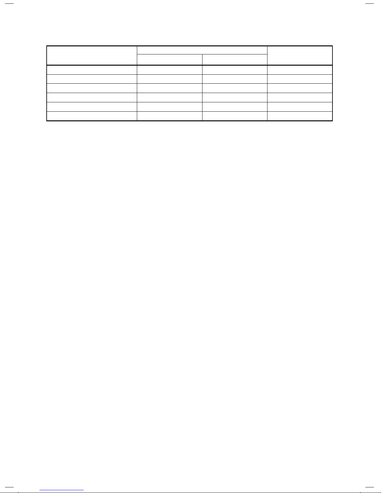
Specifications
Sound power level (dBA)
Weight (kg)
Cooling Heating
Model
RAV-GM301ATP-E
*
RAV-GM301ATJP-E
*
*
29
RAV-GM401ATP-E
*
*
32
RAV-GM401ATJP-E
*
*
32
*
*
RAV-GM301ATP-TR
*
29
RAV-GM401ATP-TR
*
32
*
: Under 70 dBA
*
29
FILE NO. SVM-18042

Refrigerant R32
This air conditioner adopts a new HFC type refrigerant (R32) which does not deplete the ozone layer.
1. Safety Caution Concerned to Refrigerant R32
Be sure that water, dust, the former refrigerant or the former refrigerating oil is not mixed into the
refrigerating cycle of the air conditioner with refrigerant R32 during installation work or service work.
If an incorrect work or incorrect service is performed, there is a possibility to cause a serious accident.
Use the tools and materials exclusive to R32 to purpose a safe work.
2. Safety and Cautions on Installation/Service
<Safety items>
When gas concentration and ignition energy are happened at the same time,
R32 has a slight possibility of burning. Although it will not ignite under normal work
environment conditions, be aware that the flame spreads if ignition should occur.
It is necessary to carry out installation/servicing safely while taking the following
precautions into consideration.
1) Never use refrigerant other than specified refrigerant (R32) in an air conditioner which is designed
to operate with the specified refrigerant (R32).
If other refrigerant than R32 is used, it may cause personal injury, etc. by a malfunction,
a fire, a rupture.
2) Since R32 is heavier than air, it tends to accumulate on the bottom (near the floor).
Ventilate properly for the working environment to prevent its combustion.
Especially in a basement or a closed room where is the high risk of the accumulation,
ventilate the room with a local exhaust ventilation.
If refrigerant leakage is confirmed in the room or the place where the ventilation is insufficient,
do not work until the proper ventilation is performed and the work environment is improved.
3) When performing brazing work, be sure to check for leakage refrigerant or residual refrigerant.
If the leakage refrigerant comes into contact with fire, a poisonous gas may
occur or it may cause a fire. Keep adequate ventilation during the work.
4) When refrigerant gas leaks during work, execute ventilation. If the leakage refrigerant comes into
contact with a fire, a poisonous gas may occur or it may cause a fire.
5) In places where installing / repairing air-conditioning equipment, etc., keep the source
of ignition such as gas combustion equipment, petroleum combustion equipment,
electric heater etc. away. Do not smoke in the place.
6) When installing or removing an air conditioner, do not mix air in the refrigerant cycle.
If air or others is mixed with the refrigerant, abnormal high pressure generates in the refrigerating
cycle, causing injury due to the breakage.
7) After installation work complete, confirm that refrigerant gas is not leaking on the flare
connection part or others. If leaked refrigerant comes to contact with a fire,
toxic gas may occur, causing a fire.
8) Perform the installation work and re-installation according to the installation manual.
Pay attention especially to the area of application. Improper installation may cause
refrigeration trouble or water leakage, electric shock and fire etc.
9) Unauthorized modifications to the air conditioner may be dangerous. If a breakdown
occurs please call a qualified air conditioner technician or electrician.
Improper repair may result in water leakage, electric shock and fire, etc.
10)Carry out the airtight test with nitrogen at a specified pressure. Do not use oxygen or
acetylene gas absolutely as it may cause an explosion.
11)Always carry a refrigerant leakage detection sensor during the work and work while
checking that no refrigerant leaks around working environment.
12)If the leakage refrigerant comes into contact with fire, it may cause a fire.
Have a dry powder or CO
2 fire extinguisher adjacent to the charging area.
FILE NO. SVM-18042
– 14 –
<Caution items>
1) The opposite side dimension of the air-conditioner's flared nut using R32 and the
shape of the charge port are the same as those of R410A.
2) Be careful not to charge refrigerant by mistake. Should the different type of refrigerant mix in,
be sure to recharge the refrigerant
3) Do not mix the other refrigerant or refrigerating oil with the refrigerant.
4) Since the pressure of R32 is high 1.6 times of that of the former refrigerant (R22),
use tools and parts with high pressure withstand specification similar to R410A.
5) In the installation time, use clean pipe materials and work with great attention so that
water and others do not mix in because
pipes are affected by impurities such as water,
oxide film, oil, etc. Use the clean pipes. Be sure to braze while flowing nitrogen gas
in the pipe. (Never use gas other than nitrogen gas.)
6) For the earth protection, use a vacuum pump for air purge.
7) R32 refrigerant is Single-component refrigerant that does not change its composition.
Although it is possible to charge the refrigerant with either liquid or gas, charge it with liquid.
(If using gas for charging, composition of the refrigerant changes and then
characteristics of the air conditioner change.)
3. Pipe Materials
For the refrigerant pipes, copper pipe and joints are mainly used.
It is necessary to select the most appropriate pipes to conform to the standard.
Use clean material in which impurities adhere inside of pipe or joint to a minimum.
1) Copper pipe
<Piping>
The pipe thickness, flare finishing size, flare nut and others differ according to a refrigerant type.
When using a long copper pipe for R32, it is recommended to select “Copper or copper-base pipe
without seam” and one with bonded oil amount 40mg/10m or less.
Also do not use crushed, deformed, discolored (especially inside) pipes.
(Impurities cause clogging of expansion valves and capillary tubes.)
<Flare nut>
Use the flare nuts which are attached to the air conditioner unit.
Be sure to select the pipes with copper thickness in the table below since the pressure of an
air conditioner using R32 is higher than that of R22.
1/2 6.4 0.80
Make sure not to use a thin copper
pipe such as 0.7 mm copper
thichness in the market.
3/8 9.5 0.80
1/2 12.7 0.80
5/8 15.9 1.00
2) Joint
The flare joint and socket joint are used for joints of the copper pipe.
The joints are rarely used for installation of the air conditioner.
However clear impurities when using them.
Nominal
diameter
Outer
diameter (mm)
Thickness (mm)
R410A or R32
FILE NO. SVM-18042
– 15 –
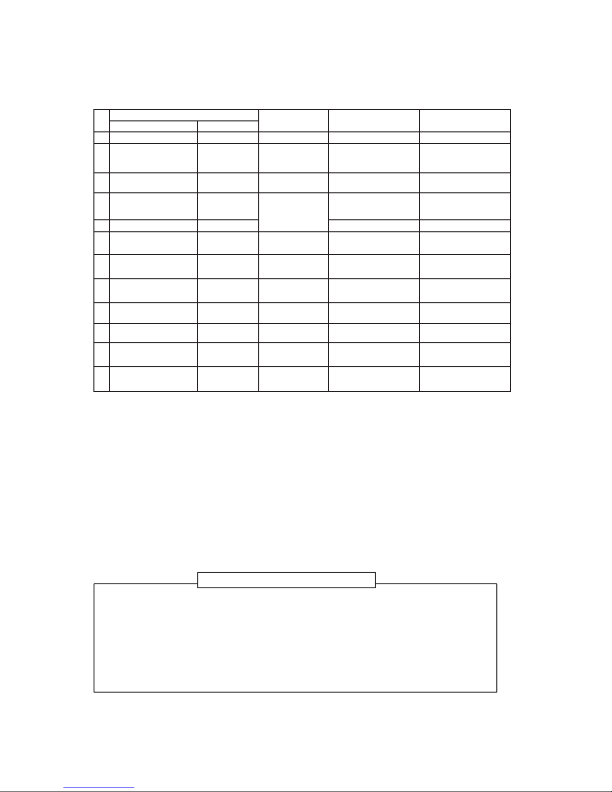
4. Tools
䕿: R410A tools available
䕧: Partly unavailable, 䖷: R410A tools unavailable
Tools / Equipment specification
1 Flare tool Clutch type Pipe flaring 䕿䕿
2
Copper pipe gauge for
adjusting projection
margin
䇷
Flaring by
conventional
flare tool
䕿 ʊ
3 Torque wrench 䇷
Tightening of
flare nut
䕿䖷
4 Gauge manifold
Port size
1/2"-20UNF
(5/16" Flare)
䕿䚷Note 2 䖷
5 Charge hose High-voltage 䕿䖷
6 Vacuum pump
䇷
Vacuum
drying
䕿䚷Note 3
1/2"-20UNF(5/16" Flare)
䕧 Connection diameter
1/4"
7 Vacuum pump adapter
䇷
Vacuum
drying
䕿䚷Note 4
1/2"-20UNF(5/16" Flare)
䕧 Connection diameter
1/4"
8
Electronic balance for
refrigerant charging
For 10 kg or
20 kg cylinder
Refrigerant
charge
䕿䕿
9 Leakage detector 䇷
Gas leakage
check
䕿䚷Note 5 䕿䚷Note 5
10 Refrigerant cylinder 䇷
Refrigerant
charge
䖷䚷Note 6 䖷
11
Refrigerant recovery
cylinder
Exclusive for
R32
Refrigerant
recovery container
䖷䚷Note 7
䖷
12
Refrigerant recovery
device
䇷
Refrigerant
recovery device
䕿䚷Note 8
䕧 Connection diameter
1/4"
Note 1 When flaring is carried out for R410A or R32 using the conventional flare tools, adjustment of
projection margin is necessary. For this adjustment, a copper pipe gauge, etc. are necessary.
Note 2 When saturation temperature is described, the gauge manifold differs for R410A and R32.
If saturation temperature reading is required, special tools exclusive for R32 are required.
Note 3 Since R32 has a slight possibility of burning, be sure to use the tools corresponding to R32.
Note 4 Like R410, a Vacuum pump adapter needs installing to prevent a Vacuum pump oil (mineral oil) from
flowing backward into the Charge hose. Mixing of the Vacuum pump oil into R32 refrigerant may
cause a trouble such as generation of sludge, clogging of capillary, etc.
Note 5 Be sure to use those tools after confirming they correspond to each refrigerant.
Note 6 For a refrigerant cylinder exclusive for R32, the paint color (or label color) of the cylinder is set to
the specified color (light blue) together with the indication of the refrigerant name.
Note 7 Although the container specification is the same as R410A, use a recovering container exclusive
for R32 to avoid mixing with other refrigerants.
Note 8 Be careful for miss-charging of the refrigerant during work. Miss-charging of the refrigerant type
may cause not only damage of the equipments but also a fire etc.
In addition to the above exclusive tools, the following equipments are necessary as the general tools.
6) Spanner or Monkey wrench
7) Hole core drill
8) Tape measure
9) Metal saw
1) Pipe cutter
2) Reamer
3) Pipe bender
4) Level vial
5) Screwdriver (+, –)
Also prepare the following equipments for other installation method and run check.
1) Clamp meter
2) Thermometer
3) Insulation resistance tester (Megger)
4) Electroscope
Evacuating,
refrigerant
charge, run
check, etc.
Installation/service tools
Use
Applicability to R32 air
conditioner or not
Applicability to R22 air
conditioner or not
No
General tools
ToolsexclusiveforR410A(ThefollowingtoolsforR410Aarerequired.)
FILE NO. SVM-18042
– 16 –
– 17 –
1. SPECIFICATIONS
1-1. Outdoor Unit
<Digital Inverter>
Model name Outdoor unit
RAV-GM
301AT*P
*
401AT*P
*
Power supply
1 phase 220-240V, 50Hz
1 phase 220V, 60Hz
Compressor
Type
Rotary DC Invertor
Motor (kW)
0.75 1.1
Pole 4 4
Refrigerant charged (kg)
0.63 0.90
Refrigerant control Pulse motor valve
Inter
connecting pipe
Standard length (m) 7.5 7.5
Min. length (m)
2.0 2.0
Max. total length (m)
20 20
Additional refrigerant charge
under long piping connector
20g/m
(15m to 20m)
20g/m
(15m to 20m)
Height
difference
Outdoor lower (m)
10 10
Outdoor higher (m)
10 10
Outer dimension
Height (mm) 550 550
Width (mm) 780 780
Depth (mm) 290 290
Appearance Silky shade (Muncel 1Y8.5/0.5)
Total weight (kg)
29
34
Heat exchanger Finned tube
Fan unit
Fan Propeller fan
Standard air flow high (m3/min.)
30 37
Motor (W) 43 43
Connecting pipe
Gas side (mm)
9.5 12.7
Liquid side (mm) 6.4
6.4
Sound pressure level Cooling/Heating (dB·A)
46/47 4
9/50
Sound power level Cooling/Heating (dB·A)
61/62 64/65
Outside air temperature, Cooling °C (Dry bulb temp.)
46 to -15
Outside air temperature, Heating °C (Wet bulb temp.)
24 to -15
FILE NO. SVM-18042
–
18 –
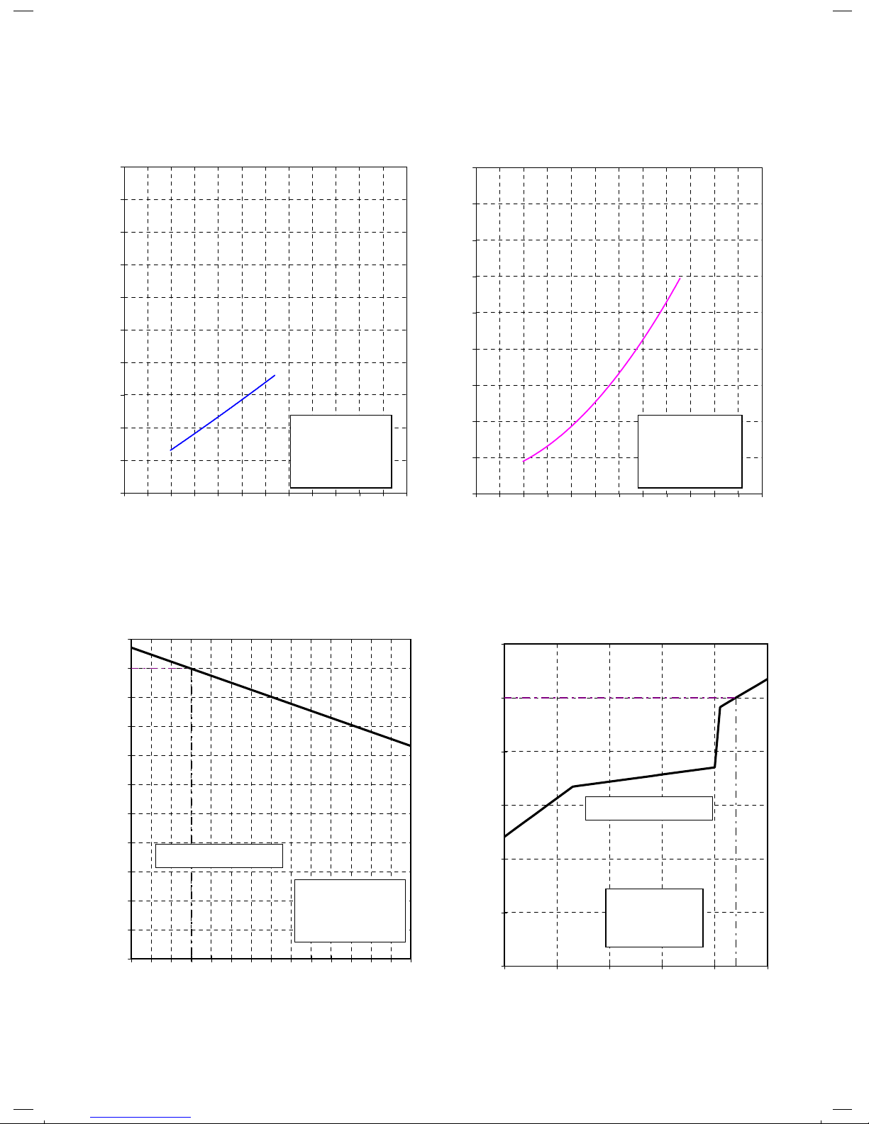
ë Capacity variation ratio according to temperature
>gnitaeH<
>gnitaeH<>gnilooC<
0
1
2
3
4
5
6
7
8
9
1-2. Operation Characteristic Curve
RAV-GM301ATP
<Cooling>
10
0 10 20 30 40 50 60 70 80 90 100 110 120
Compressor Speed (rps)
Current (A)
0
1
2
3
4
5
6
7
8
9
0 10 02 0430 50 06 07 08 90100110120
Compressor Speed (rps)
Current (A)
Conditions
Indoor : DB 27
o
C/WB 19oC
Outdoor : DB 35
o
C
Air Flow : High
Pip Length : 7.5m
Voltage : 230V
Conditions
Indoor : DB 20
o
C
Outdoor : DB 7
o
C/WB 6oC
Air Flow : High
Pip Length : 7.5m
Voltage : 230V
50
55
60
65
70
75
80
85
90
95
100
105
32 33 34 35 36 37 38 39 40 41 42 43 44 45 46
Outdoor temp. (℃)
Capacity ratio (%)
Conditions
Indoor:DB27℃/WB19℃
Indoor air flow:High
Pipe length:7.5m
0
20
40
60
80
100
120
-15 -10 -5 0 5 10
Outdoor temp. (℃)
Heating Capacity ratio (%)
Condition
Indoor:DB20℃
Indoor air flow:High
Pipe length:7.5m
Voltage : 230V
Voltage : 230V
Capacity ratio:100%=3.4kW
Capacity ratio:100%= 2.5
kW
FILE NO. SVM-18042
–
19 –
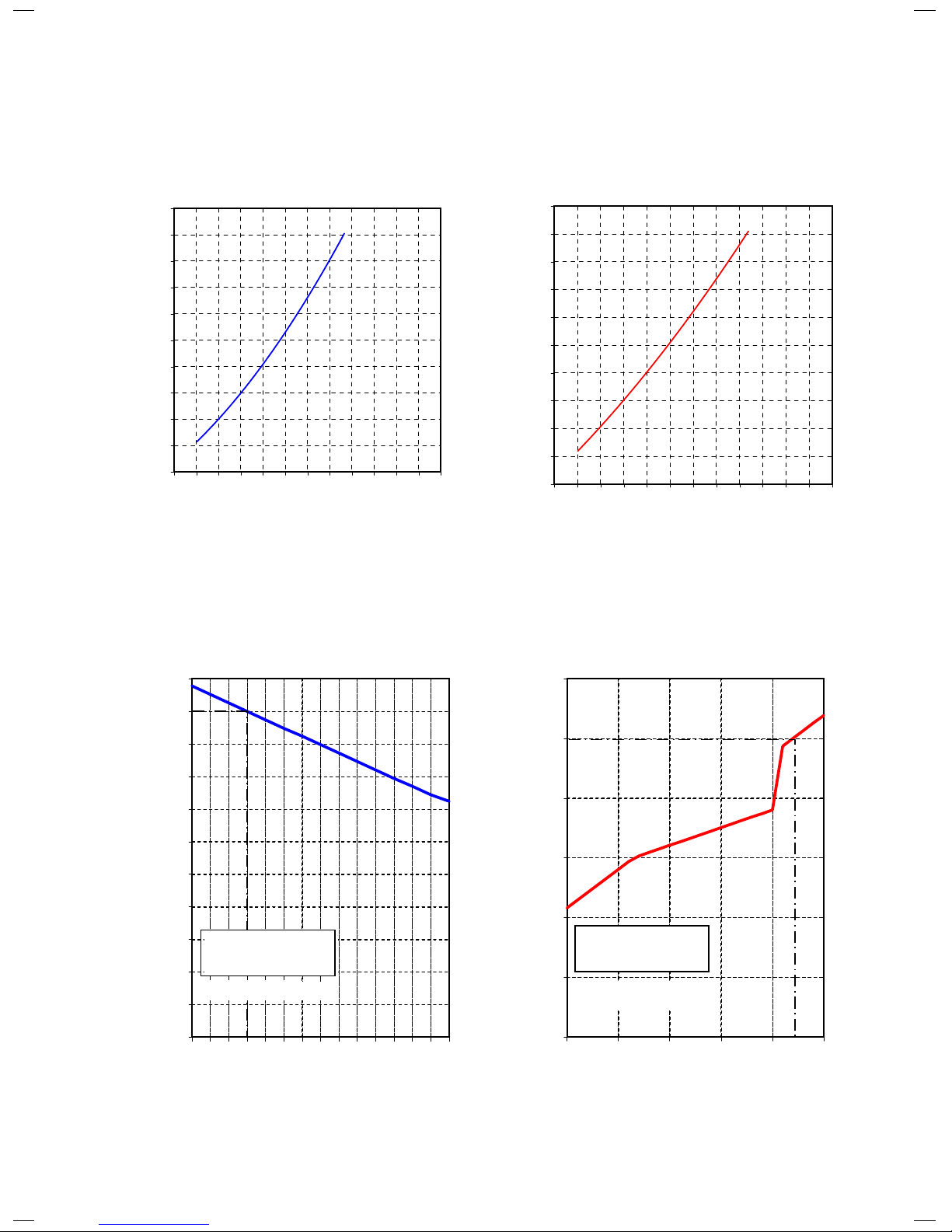
>gnitaeH<
>gnitaeH<>gnilooC<
ë Capacity variation ratio according to temperature
ë Operation Characteristic Curve
RAV-GM401ATP
<Cooling>
0.00
1.00
2.00
3.00
4.00
5.00
6.00
7.00
8.00
9.00
10.00
0 102030405060708090100110120
Compressor Speed (RPS)
Current (A)
0.00
1.00
2.00
3.00
4.00
5.00
6.00
7.00
8.00
9.00
10.00
0 01 20 03 0540 60 07 08 90100110120
Compressor Speed (RPS)
Current (A)
120
100
80
60
40
20
0
Outdoor Temperature (°C)
100
95
90
85
80
75
70
65
60
55
50
105
15– –10–50 51032 33 34 35 36 37 38 39 40 41 42 43 44 45 46
Outdoor Temperature (°C)
Capacity Ratio (%)
Capacity Ratio (%)
Condition
Indoor: DB20°C
Indoor Air-Flow Volume: High
Pipe Length: 7.5m
Condition
Indoor: DB27°C/WB19°C
Indoor Air-Flow Volume: High
Pipe Length: 7.5m
Capacity Ratio : 100% = 3.6kW
Capacity Ratio : 100% = 4.0kW
FILE NO. SVM-18042
–
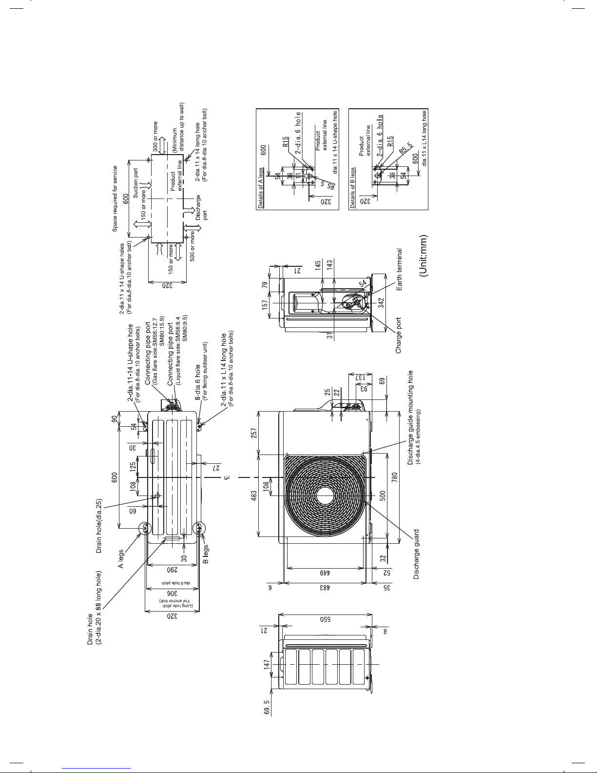
20 –
2. CONSTRUCTION VIEWS (EXTERNAL VIEWS)
2-1. RAV-GM301AT*P*, GM401AT*P
*
FILE NO. SVM-18042
–
21 –
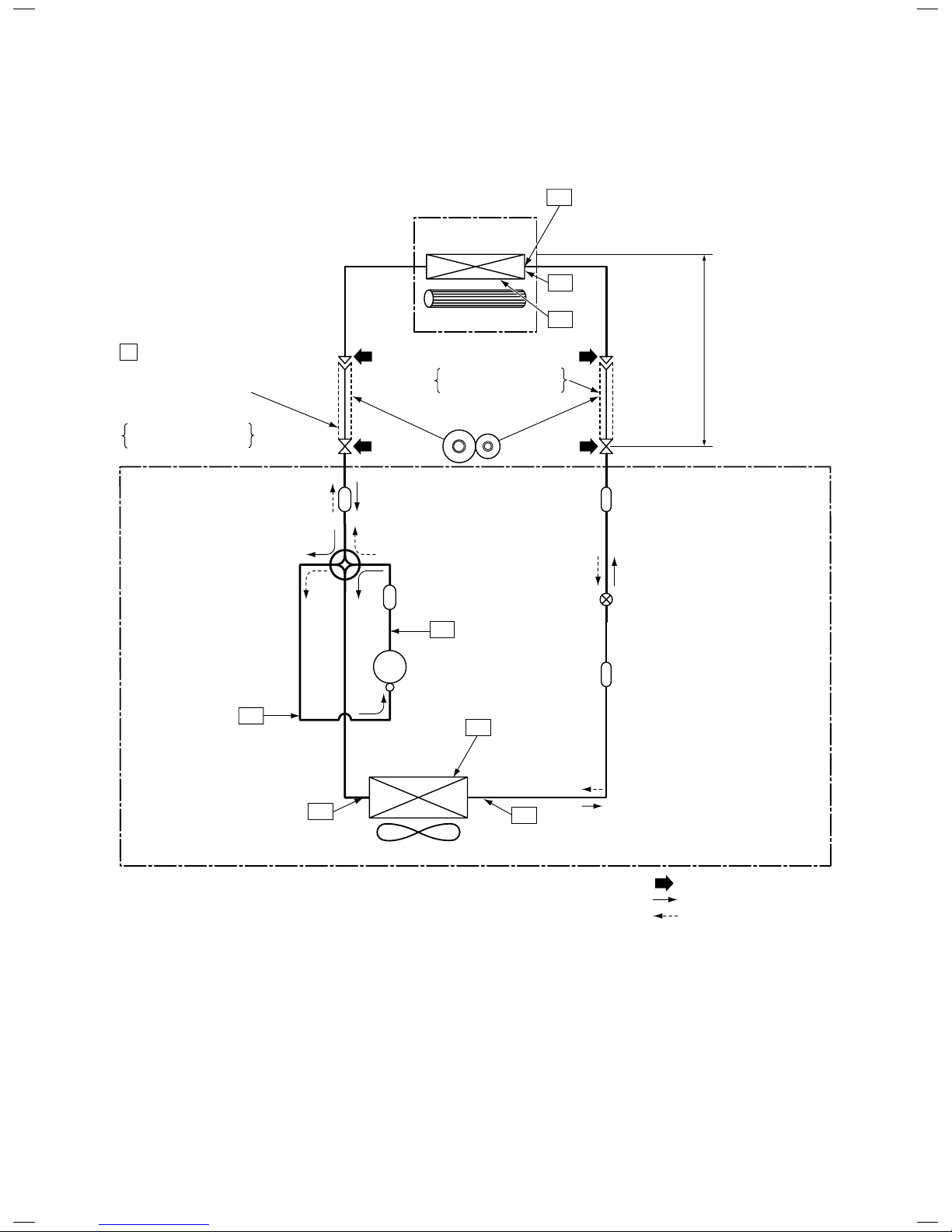
3-1. Outdoor Unit
RAV-GM301AT∗P∗
3. SYSTEMATIC REFRIGERATING CYCLE DIAGRAM
NOTE :
•
Deoxidized copper pipe
Outer dia. : 9.52mm
Thickness : 0.8mm
NOTE :
Gas leak check position
Refrigerant flow (Cooling)
Refrigerant flow (Heating)
T1
TO
Temp. measurement
TC
TA
INDOOR UNIT
Indoor heat
exchanger
Cross flow fan
Deoxidized copper pipe
Outer dia. : 6.35mm
Thickness : 0.8mm
Sectional shape
of heat insulator
Allowable height
difference : 10m
Allowable pipe length
P Pressure measurement
Gauge attaching port
Vacuum pump connecting port
Strainer
Pulse Modulating
valve at liquid side
TD
4-way valve
Compressor
TS
T2
Outdoor heat
exchanger
Temp. measurement
Refrigerant amount : 0.80kg
Propeller fan
OUTDOOR UNIT
Muffler
Muffler
TE
Max. : 20m
Min. : 2m
Chargeless : 15m
Strainer
Charge : 20g/m
(16 to 20m)
The maximum pipe length of this air conditioner is 20 m. When the pipe length exceeds 15m, the additional
charging of refrigerant, 20g per 1m for the part of pipe exceeded 15m is required. (Max. 100g)
FILE NO. SVM-18042
–
22 –
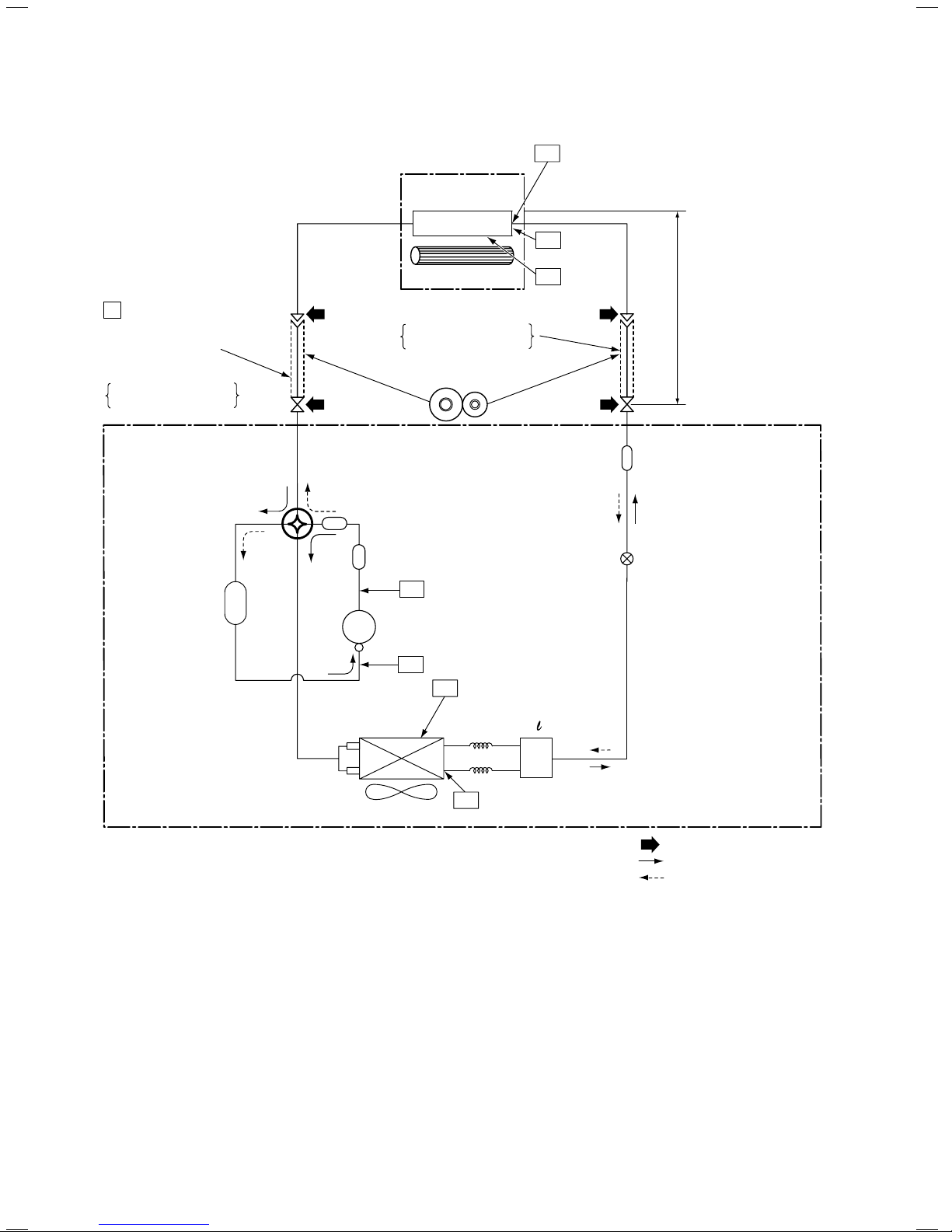
RAV-GM401ATP
NOTE :
• The maximum pipe length of this air conditioner is 20m. When the pipe length exceeds 15m, the additional
charging of refrigerant, 20g per 1m for the part of pipe exceeded 15m is required. (Max. 100g)
Max. 20m:
Min. : 2m
Chargeless : 15m
Charge : 20g/m
(16 to 20m)
Deoxidized copper pipe
Outer dia. : 12.7mm
Thickness : 0.8mm
NOTE:
Gas leak check position
Refrigerant flow (Cooling)
Refrigerant flow (Heating)
T1 Temp. measurement
INDOOR UNIT
Indoor heat
exchanger
Cross flow fan
Sectional shape
of heat insulator
Allowable height
difference: 10m
Allowable pipe length
P Pressure measurement
Gauge attaching port
Vacuum pump connecting port
Strainer
Pulse Modulating valve
at liquid side
(CAM-BD16TCTH-2)
TD
4-way valve
(STF-0108-Z)
Compressor
Propeller fan
Refrigerant amount: 1.40kg
OUTDOOR UNIT
TC
TA
exchanger
Split capillary
2-dia. 1.2 × 80
Outdoor heat
TE
Muffler
Muffler
Accumulater tank
Deoxidized copper pipe
Outer dia. : 6.35mm
Thickness : 0.8mm
TS
TO
Distributor
FILE NO. SVM-18042
–
23 –
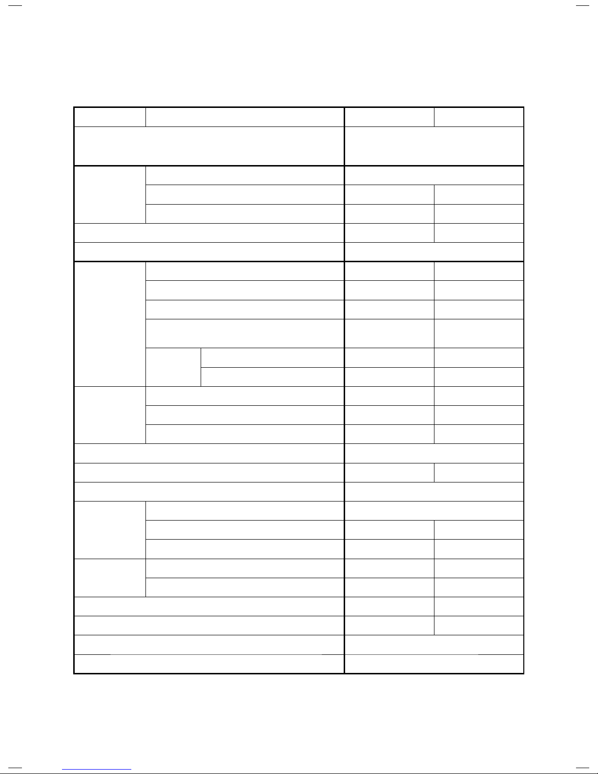
<Heating>
Standard Indoor Outdoor Compressor
pressure fan mode fan mode revolution
P (MPa)
TC (°C) TS (°C)
(rps)
0.9 to 1.1
13 to 15 13 to 15
High High
46
Heat exchanger pipe
temp.
Standard
Indoor Outdoor Compressor
pressure
fan mode fan mode revolution
Indoor Outdoor
P (MPa)
TC (°C) TS (°C)
(rps)
20/-
7/6
2.5 to 2.7
35 to 37 5 to 6
High High
74
Tempeature
condition(°C)
Heat exchanger
pipe temp.
<Heating>
Standard Indoor Outdoor Compressor
pressure fan mode fan mode revolution
P (MPa)
TC (°C) TS (°C)
(rps)
0.9 to 1.1
11 to 13 11 to 13
High High
51
Heat exchanger
pipe temp.
Standard Indoor Outdoor Compressor
pressure fan mode fan mode revolution
P (MPa)
TC (°C) TS (°C)
(rps)
2.5 to 2.6 35 to 42 4 to 6
High High
53
Heat exchanger
pipe temp.
Indoor Outdoor
27/19 35/-
Tempeature
condition(°C)
3-2. Operation Data
RAV-GM301ATP
<Cooling>
RAV-GM401ATP
<Cooling>
Indoor Outdoor
27/19
35/-
Tempeature
condition(°C)
Indoor Outdoor
20/-
Tempeature
condition(°C)
7/6
TE (°C)
37 to 41
TE (°C)
3 to 5
TE (°C)
39 to 42
TE (°C)
3 to 5
FILE NO. SVM-18042
–
24 –
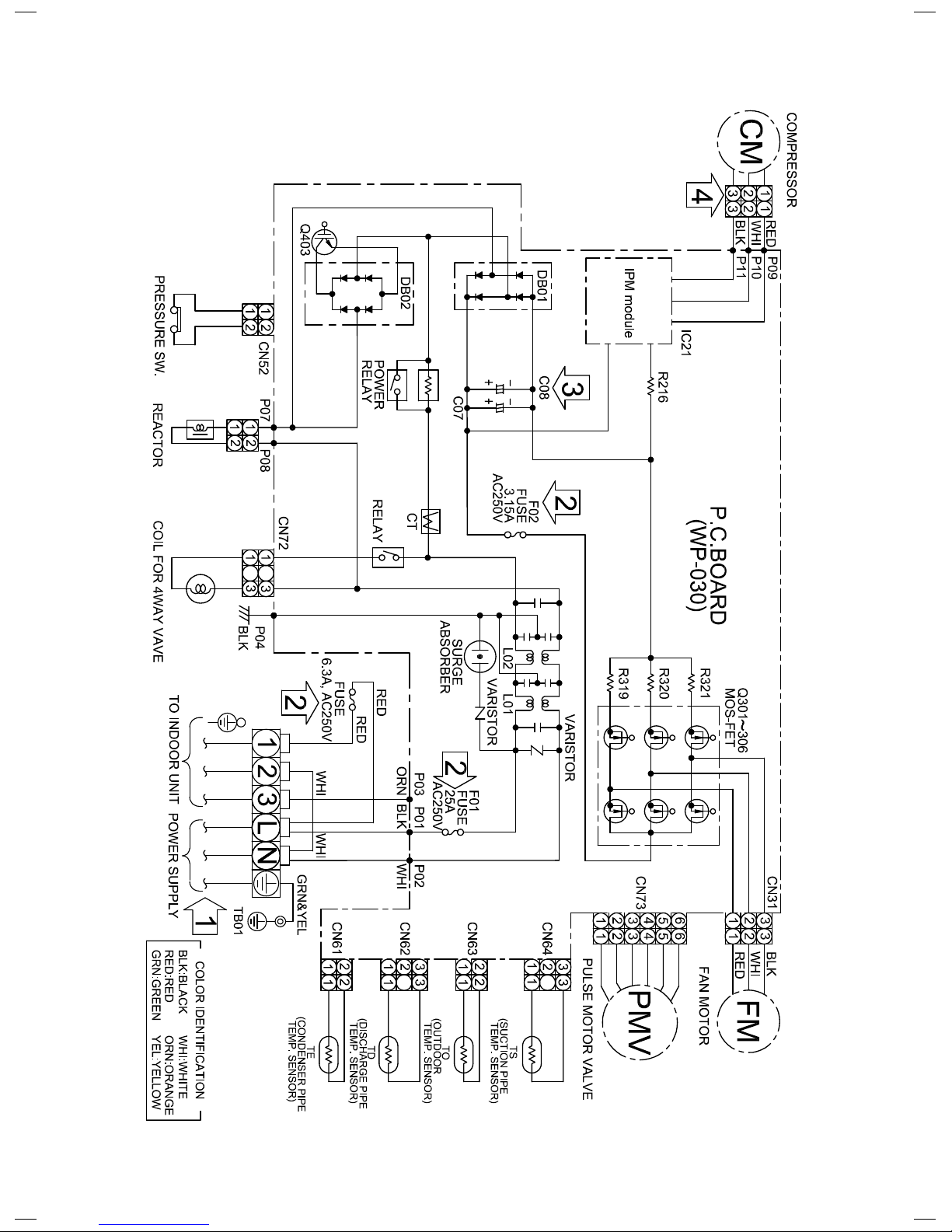
4. WIRING DIAGRAM
4. RAV-GM301AT*P*, GM401AT*P*
FILE NO. SVM-18042
–
25 –
5. SPECIFICATIONS OF ELECTRICAL PARTS
RAV-GM301AT*P
*
No. Parts name Type Specifications
1 Compressor
KSK89D53UFZ
3 phase, 6P, 712W
2 Fan motor
WDF-340-A43-1
Output 43 W
3 4-way valve coil
SQ-A2522G-00352
-
4 PMV coil
PQ-M10012-000313
-
5
6
Reactor
CH-69-Z-T 19mH, 10A
7
P.C. board
WP-030
-
8
Fuse (Mounted on P.C. board) - AC250 V, 25 A
9
Fuse - AC250 V, 6.3 A
10
Fuse (Mounted on P.C. board) - AC250 V, 3.15 A
11
Outdoor temp. sensor (TO sensor) - 10 kΩ at 25°C
12
Heat exchanger temp. sensor (TE sensor) - 10 kΩ at 25°C
13
Suction temp. sensor (TS sensor) - 10 kΩ at 25°C
Discharge temp. sensor (TD sensor) -
3.3 kΩ at 100°C
RAV-GM401AT*P
*
No. Parts name Type Specifications
1 Compressor
KTN130D30UFZ
3 phase, 6P, 1075W
2 Fan motor
WDF-340-A43-1 Output 43 W
3 4-way valve coil
SQ-A2522G-000352
-
4 PMV coil
PQ-M10012-000313
-
5
6
Reactor
7
P.C. board
WP-030
-
8
Fuse (Mounted on P.C. board) - AC250 V, 25 A
9
Fuse - AC250 V, 10 A
10
Fuse (Mounted on P.C. board) - AC250 V, 3.15 A
11
Outdoor temp. sensor (TO sensor) - 10 kΩ at 25°C
12
Heat exchanger temp. sensor (TE sensor) - 10 kΩ at 25°C
13
Suction temp. sensor (TS sensor) - 10 kΩ at 25°C
Discharge temp. sensor (TD sensor) -
3.3 kΩ at 100°C
CH-69-Z-T
19mH, 10A
FILE NO. SVM-18042-1

–
26 –
This air conditioner adopted the R32 refrigerant
which does not damage the ozone layer.
The working pressure of the refrigerant R32
is 1.6 times higher than conventional refrigerant
(R22). The refrigerating oil is also changed in
accordance with change of refrigerant, so be careful
that water, dust, and existing refrigerant or
refrigerating oil are not entered in the refrigerant
cycle of the air conditioner using the new refrigerant
during installation work or servicing time.
The next section describes the precautions for air
conditioner using the
refrigerant.
Conforming to contents of the next section together
with the general cautions included in this manual,
perform the correct and safe work.
6-1. Safety During Installation/Servicing
As R32’s pressure is about 1.6 times higher than
that of R22, improper installation/servicing may
cause a serious trouble. By using tools and
materials exclusive for R32, it is necessary to carry
out installation/servicing safely while taking the
following precautions into consideration.
1. Never use refrigerant other than R32 in an air
conditioner which is designed to operate with
R32.
If other refrigerant than R32 is mixed, pressure in
the refrigeration cycle becomes abnormally high,
and it may cause personal injury, etc. by a
rupture.
2. Confirm the used refrigerant name, and use tools
and materials exclusive for the refrigerant R32.
The refrigerant name R32 is indicated on the
visible place of the outdoor unit of the air
conditioner using R32 as refrigerant.
A diameter of charge port for R32 is the
same as
that of the R410's Be careful not to charge the
refrigerant by mistake.
3. If a refrigeration gas leakage occurs during
installation/servicing, be sure to ventilate fully. If
the refrigerant gas comes into contact with fire, a
poisonous gas may occur.
4. When installing or removing an air conditioner,
do not allow air or moisture to remain in the
refrigeration cycle.
Otherwise, pressure in the refrigeration cycle
may become abnormally high so that a rupture or
personal injury may be caused.
5. After completion of installation work, check to
make sure that there is no refrigeration gas
leakage.
If the refrigerant gas leaks into the room, coming
into contact with fire in the fan-driven heater,
space heater, etc., a poisonous gas may occur.
6. When an air conditioning system charged with a
large volume of refrigerant is installed in a small
room, it is necessary to exercise care so that,
even when refrigerant leaks, its concentration
does not exceed the marginal level.
If the refrigerant gas leakage occurs and its
concentration exceeds the marginal level, an
oxygen starvation accident may result.
7. Be sure to carry out installation or removal
according to the installation manual.
Improper installation may cause refrigeration
trouble, water leakage, electric shock, fire, etc.
8. Unauthorized modifications to the air conditioner
may be dangerous. If a breakdown occurs
please call a qualified air conditioner technician
or electrician.
Improper repair may result in water leakage,
electric shock and fire, etc.
6-2. Refrigerant Piping Installation
6-2-1. Piping Materials and Joints Used
For the refrigerant piping installation, copper pipes
and joints are mainly used.
Copper pipes and joints suitable for the refrigerant
must be chosen and installed.
Furthermore, it is necessary to use clean copper
pipes and joints whose interior surfaces are less
affected by contaminants.
1. Copper Pipes
It is necessary to use seamless copper pipes
which are made of either copper or copper alloy
and it is desirable that the amount of residual oil
is less than 40 mg/10 m.
Do not use copper pipes having a collapsed,
deformed or discolored portion (especially on
the interior surface).
Otherwise, the expansion valve or capillary tube
may become blocked with contaminants.
As an air conditioner using R32 incurs pres-sure
higher than when using R22, it is necessary to
choose adequate materials.
Thicknesses of copper pipes used with R32 are
as shown in Table 6-2-1. Never use copper pipes
thinner than 0.8mm even when it is avail-able on
the market.
NOTE:
Refer to the “6-6. Instructions for Re-use Piping
of R22 or R407C”.
6. REFRIGERANT R32
FILE NO. SVM-18042-1
–
27 –
Table 6-2-1 Thicknesses of annealed copper pipes
1. Joints
For copper pipes, flare joints or socket joints are used. Prior to use, be sure to remove all contaminants.
a) Flare Joints
Flare joints used to connect the copper pipes cannot be used for pipings whose outer diameter exceeds
20 mm. In such a case, socket joints can be used.
Sizes of flare pipe ends, flare joint ends and flare nuts are as shown in Tables 6-2-3 to 6-2-5 below.
b) Socket Joints
Socket joints are such that they are brazed for connections, and used mainly for thick pipings whose
diameter is larger than 20 mm. Thicknesses of socket joints are as shown in Table 6-2-2.
Table 6-2-2 Minimum thicknesses of socket joints
6-2-2. Processing of Piping Materials
When performing the refrigerant piping installation, care should be taken to ensure that water or dust does not
enter the pipe interior, that no other oil other than lubricating oils used in the installed air conditioner is used,
and that refrigerant does not leak.
When using lubricating oils in the piping processing, use such lubricating oils whose water content has been
removed. When stored, be sure to seal the container with an airtight cap or any other cover.
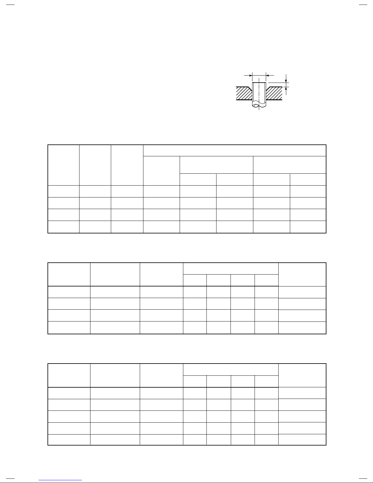
1. Flare Processing Procedures and Precautions
a) Cutting the Pipe
By means of a pipe cutter, slowly cut the pipe so that it is not
deformed.
b) Removing Burrs and Chips
If the flared section has chips or burrs, refrigerant leakage may occur.
Carefully remove all burrs and clean the cut surface before installation.
Nominal diameter
1/4
3/8
1/2
5/8
Outer diameter (mm)
6.4
9.5
12.7
15.9
Thickness (mm)
22R
R32
08.008.0
08.008.0
08.008.0
00.100.1
Nominal diameter
1/4
3/8
1/2
5/8
Reference outer diameter of
copper pipe jointed (mm)
6.4
9.5
12.7
15.9
Minimum joint thickness
(mm)
0.50
0.60
0.70
0.80
FILE NO. SVM-18042-1
–
28 –
c) Insertion of Flare Nut
d) Flare Processing
Make certain that a clamp bar and copper pipe have been cleaned.
By means of the clamp bar, perform the flare processing correctly.
Use either a flare tool for R410A/R32 or conventional flare tool.
Flare processing dimensions differ according
to the type of flare tool.
When using a conventional flare tool, be sure
to secure “dimension A” by using a gauge for
size adjustment.
Fig. 6-2-1 Flare processing dimensions
Table 6-2-3 Dimensions related to flare processing for R410A/ R32 / R22
A
ØD
Nominal
diameter
1/4
3/8
1/2
5/8
Outer
diameter
(mm)
6.4
9.5
12.7
15.9
Thickness
(mm)
0.8
0.8
0.8
1.0
A (mm)
Flare tool for
R410A, R22
clutch type
0 to 0.5
0 to 0.5
0 to 0.5
0 to 0.5
Conventional flare tool
(R410A or R32)
Clutch type Wing nut type
1.0 to 1.5 1.5 to 2.0
1.0 to 1.5 1.5 to 2.0
1.0 to 1.5 2.0 to 2.5
1.0 to 1.5 2.0 to 2.5
Conventional flare tool
(R22)
Clutch type Wing nut type
0.5 to 1.0 1.0 to 1.5
0.5 to 1.0 1.0 to 1.5
0.5 to 1.0 1.5 to 2.0
0.5 to 1.0 1.5 to 2.0
Table 6-2-4 Flare and flare nut dimensions for R410A/ R32
Table 6-2-5 Flare and flare nut dimensions for R22
Nominal
diameter
1/4
3/8
1/2
5/8
Outer diameter
(mm)
6.4
9.5
12.7
15.9
Thickness
(mm)
0.8
0.8
0.8
1.0
Dimension (mm)
ABCD
9.1 9.2 6.5 13
13.2 13.5 9.7 20
16.6 16.0 12.9 23
19.7 19.0 16.0 25
Flare nut width
(mm)
17
22
26
29
Nominal
diameter
1/4
3/8
1/2
5/8
3/4
Outer diameter
(mm)
6.4
9.5
12.7
15.9
19.0
Thickness
(mm)
0.8
0.8
0.8
1.0
1.0
Dimension (mm)
ABCD
9.1 9.2 6.5 13
13.0 13.5 9.7 20
16.2 16.0 12.9 20
19.4 19.0 16.0 23
23.3 24.0 19.2 34
Flare nut width
(mm)
17
22
24
27
36
FILE NO. SVM-18042-1
–
29 –
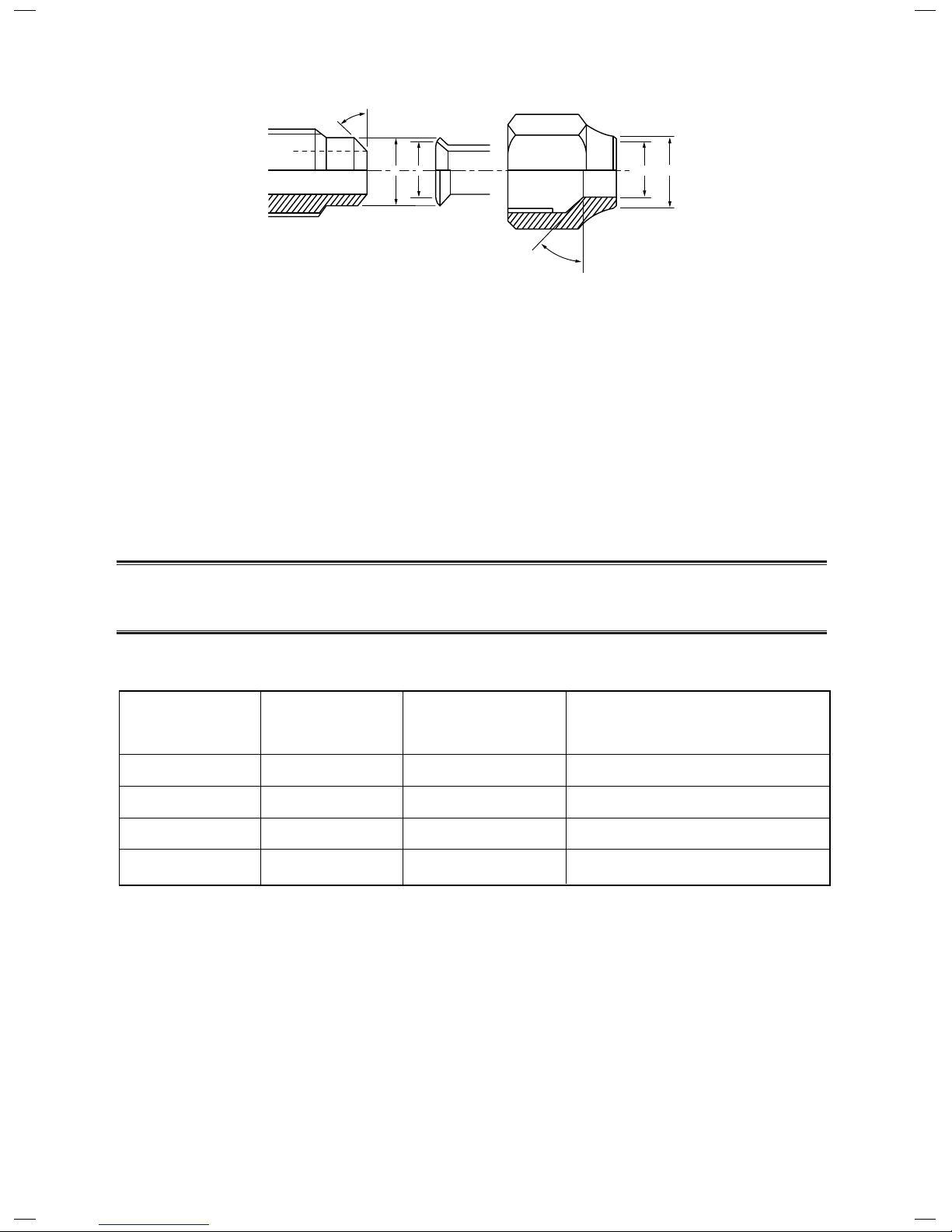
43˚to 45˚
45˚to 46˚
A B
C
D
Fig. 6-2-2 Relations between flare nut and flare seal surface
2. Flare Connecting Procedures and Precautions
a) Make sure that the flare and union portions do not have any scar or dust, etc.
b) Correctly align the processed flare surface with the union axis.
c) Tighten the flare with designated torque by means of a torque wrench.
The tightening torque for R410A or R32 is the same as that for conventional R22.
Incidentally, when the torque is weak, the gas leakage may occur.
When it is strong, the flare nut may crack and may be made non-removable.
When choosing the tightening torque, comply with values designated by manufacturers.
Table 6-2-6 shows reference values.
NOTE:
When applying oil to the flare surface, be sure to use oil designated by the manufacturer.
If any other oil is used, the lubricating oils may deteriorate and cause the compressor to burn out.
Table 6-2-6 Tightening torque of flare for R410A or R32 [Reference values]
Nominal
diameter
1/4
3/8
1/2
5/8
Outer diameter
(mm)
6.4
9.5
12.7
15.9
Tightening torque
N•m (kgf•m)
14 to 18 (1.4 to 1.8)
33 to 42 (3.3 to 4.2)
50 to 62 (5.0 to 6.2)
63 to 77 (6.3 to 7.7)
wrenches available on the market
N•m (kgf•m)
16 (1.6), 18 (1.8)
42 (4.2)
55 (5.5)
65 (6.5)
Tightening torque of torque
FILE NO. SVM-18042-1
–
30 –
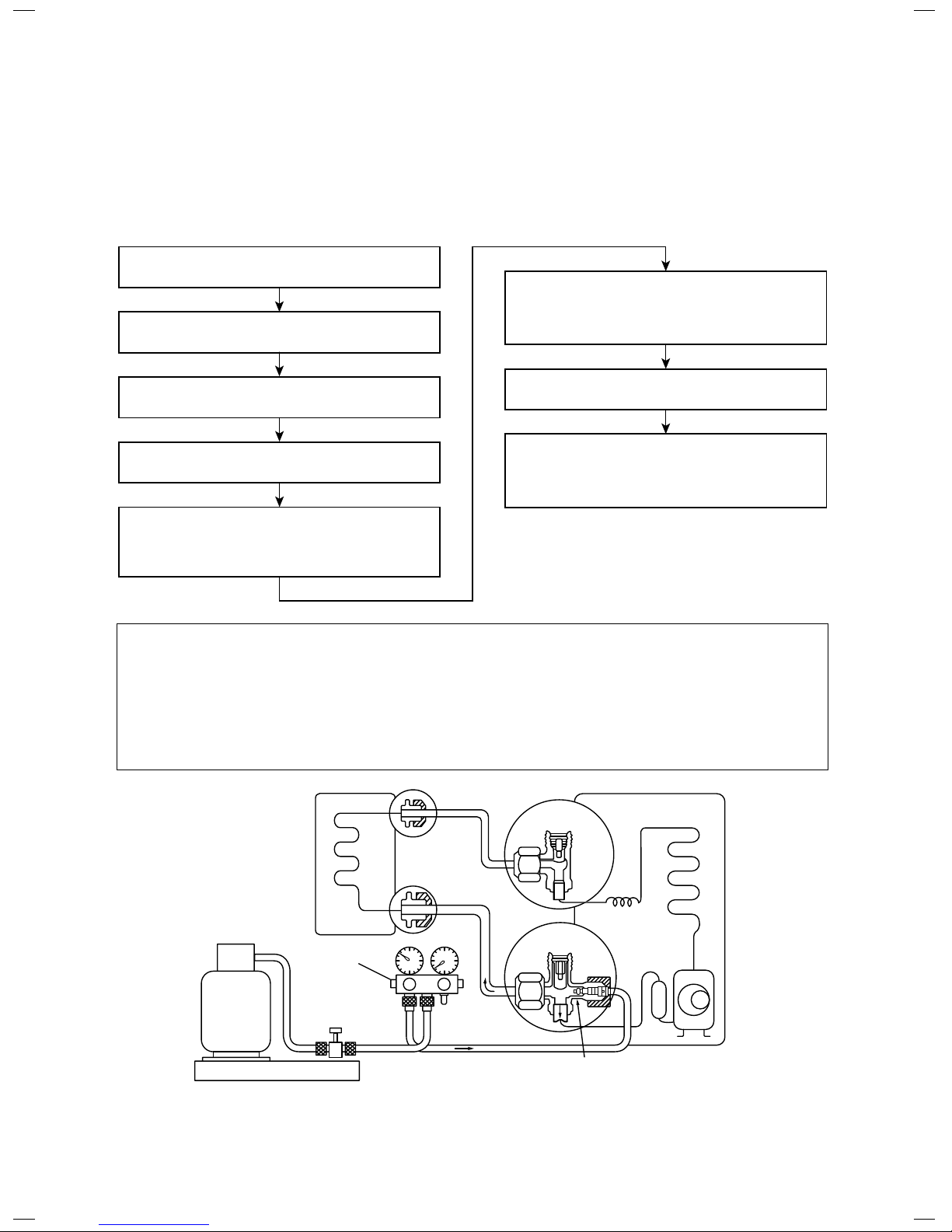
When it is necessary to recharge refrigerant, charge the specified amount of refrigerant according to the
following steps.
(INDOOR unit)
(Liquid side)
Refrigerant cylinder
(With siphon pipe)
Check valve
(Gas side)
Open/Close valve
for charging
Electronic balance for refrigerant charging
Opened
(OUTDOOR unit)
Closed
Service port
Connect the charge hose to packed valve service
port at the outdoor unit’s gas side.
Recover the refrigerant, and check no refrigerant
remains in the equipment.
(For refrigerant charging, see the figure below.)
Connect the charge hose of the vacuum pump
adapter.
Open fully both packed valves at liquid and gas
sides.
Place the handle of the gauge manifold Low in the
fully opened position, and turn on the vacuum pump’s
power switch. Then, evacuating the refrigerant in the
cycle.
When the compound gauge’s pointer has indicated
–0.1 Mpa (–76 cmHg), place the handle Low in the
fully closed position, and turn off the vacuum pump’s
power switch.
Keep the status as it is for 1 to 2 minutes, and ensure
that the compound gauge’s pointer does not return.
Set the refrigerant cylinder to the electronic balance,
connect the connecting hose to the cylinder and the
connecting port of the electronic balance, and charge
liquid refrigerant.
1) Never charge refrigerant exceeding the specified amount.
2) If the specified amount of refrigerant cannot be charged, charge refrigerant bit by bit in COOL mode.
3) Do not carry out additional charging.
When additional charging is carried out if refrigerant leaks, the refrigerant composition changes in the
refrigeration cycle, that is characteristics of the air conditioner changes, refrigerant exceeding the
specified amount is charged, and working pressure in the refrigeration cycle becomes abnormally high
pressure, and may cause a rupture or personal injury.
Fig. 6-4-1 Configuration of refrigerant charging
6-3. Tools
6-3-1.Required Tools
Refer to the “4. Tools” (Page 13)
6-4. Recharging of Refrigerant
FILE NO. SVM-18042-1
 Loading...