

Toshiba RAV-RM401SDT-E, RAV-RM561SDT-E, RAV-RM401SDT-TR, RAV-GM561UT-E, RAV-GM801UT-TR Service Manual
...
FILE NO. A10-1812
SERVICE MANUAL
AIR-CONDITIONER (SPLIT TYPE)
INDOOR UNIT
PRINTED IN JAPAN, Mar., 2018 ToMo
<Slim Duct type>
RAV-RM301SDT-E (TR)
RAV-RM401SDT-E (TR)
RAV-RM561SDT-E (TR)

– 2 –
CONTENTS
Precaution for Safety .................................................................................................. 6
About refrigerant R32 ............................................................................................... 14
About refrigerant R410A........................................................................................... 17
1. SPECIFICATIONS .................................................................................................. 19
2. CONSTRUCTION VIEWS (EXTERNAL VIEWS) .................................................... 23
2-1. RAV-RM301SDT* ................................................................................................................ 23
2-2. RAV-RM401SDT*, RM561SDT* .......................................................................................... 24
3. WIRING DIAGRAMS .............................................................................................. 25
4. PARTS RATING ...................................................................................................... 26
5. SYSTEMATIC REFRIGERATING CYCLE DIAGRAM ........................................... 27
5-1. Indoor Unit .......................................................................................................................... 27
6. FAN CHARACTERISTICS ...................................................................................... 30
6-1. Slim Duct (Filter Attached)................................................................................................ 30
7. INDOOR CONTROL CIRCUIT ............................................................................... 31
7-1. Indoor Controller Block Diagram ..................................................................................... 31
7-1-1. Connection of Wired (Simple) Remote Controller ................................................ 31
7-1-2. Connection of Wireless Remote Controller Kit ..................................................... 32
7-1-3. Connection of Both Wired (Simple) Remote Controller and
Wireless Remote Controller Kit .............................................................................. 33
7-2. Control Specifications....................................................................................................... 34
7-3. Indoor Print Circuit Board................................................................................................. 42
7-4. Optional connector specifications of indoor P.C. board ............................................... 43
8. TROUBLESHOOTING ............................................................................................ 44
8-1. Summary of Troubleshooting ........................................................................................... 44
8-2. Troubleshooting ................................................................................................................. 46
8-2-1. Outline of judgment ................................................................................................. 46
8-2-2. Others (Other than Check Code) ............................................................................ 48
8-2-3. Check Code List (Indoor) ........................................................................................ 49
8-2-4. Diagnostic Procedure for Each Check Code (Indoor Unit) .................................. 52
9. REPLACEMENT OF SERVICE P.C. BOARD ......................................................... 63
9-1. Indoor Unit .......................................................................................................................... 63
10. SETUP AT LOCAL SITE AND OTHERS ............................................................. 68
10-1. Indoor Unit ........................................................................................................................ 68
10-1-1. Test Run Setup on Remote Controller................................................................. 68
10-1-2. Forced Defrost Setup of Remote Controller
(For wired remote controller only) ....................................................................... 69
10-1-3. LED Display on P.C. Board.................................................................................... 69
10-1-4. Function Selection Setup ..................................................................................... 70
10-1-5. Wiring and Setting of Remote Controller Control .............................................. 72
10-1-6. Monitor Function of Remote Controller Switch .................................................. 74
10-2. Setup at Local Site / Others ............................................................................................. 77
10-3. How to Set up Central Control Address Number .......................................................... 79
11. ADDRESS SETUP ............................................................................................... 80
11-1. Address Setup .................................................................................................................. 80
11-2. Address Setup & Group Control ..................................................................................... 81
11-2-1. System configuration ............................................................................................81
11-2-2. Automatic Address Example from Unset Address (No miswiring) .................. 83
11-3. Address Setup (Manual Setting from Remote Controller) ........................................... 84
11-4. Confirmation of Indoor Unit No. Position ...................................................................... 85
12. DETACHMENTS ................................................................................................... 87
13. EXPLODED VIEWS AND PARTS LIST ............................................................... 92
– 3 –
Original instruction
Please read carefully through these instructions that contain important information which complies with the
“Machinery” Directive (Directive 2006/42/EC), and ensure that you understand them.
Generic Denomination: Air Conditioner
Definition of Qualified Installer or Qualified Service Person
The air conditioner must be installed, maintained, repaired and removed by a qualified installer or qualified
service person. When any of these jobs is to be done, ask a qualified installer or qualified service person to do
them for you.
A qualified installer or qualified service person is an agent who has the qualifications and knowledge
described in the table below.
• The qualified service person is a person who installs, repairs, maintains, relocates and removes
the air conditioners made by Toshiba Carrier Corporation. He or she has been trained to install,
repair, maintain, relocate and remove the air conditioners made by Toshiba Carrier Corporation
or, alternatively, he or she has been instructed in such operations by an individual or individuals
who have been trained and is thus thoroughly acquainted with the knowledge related to these
operations.
• The qualified service person who is allowed to do the electrical work involved in installation,
repair, relocation and removal has the qualifications pertaining to this electrical work as
stipulated by the local laws and regulations, and he or she is a person who has been trained in
matters relating to electrical work on the air conditioners made by Toshiba Carrier Corporation
or, alternatively, he or she has been instructed in such matters by an individual or individuals
who have been trained and is thus thoroughly acquainted with the knowledge related to this
work.
• The qualified service person who is allowed to do the refrigerant handling and piping work
involved in installation, repair, relocation and removal has the qualifications pertaining to this
refrigerant handling and piping work as stipulated by the local laws and regulations, and he or
she is a person who has been trained in matters relating to refrigerant handling and piping work
on the air conditioners made by Toshiba Carrier Corporation or, alternatively, he or she has
been instructed in such matters by an individual or individuals who have been trained and is
thus thoroughly acquainted with the knowledge related to this work.
• The qualified service person who is allowed to work at heights has been trained in matters
relating to working at heights with the air conditioners made by Toshiba Carrier Corporation or,
alternatively, he or she has been instructed in such matters by an individual or individuals who
have been trained and is thus thoroughly acquainted with the knowledge related to this work.
• The qualified installer is a person who installs, maintains, relocates and removes the air
conditioners made by Toshiba Carrier Corporation. He or she has been trained to install,
maintain, relocate and remove the air conditioners made by Toshiba Carrier Corporation or,
alternatively, he or she has been instructed in such operations by an individual or individuals
who have been trained and is thus thoroughly acquainted with the knowledge related to these
operations.
• The qualified installer who is allowed to do the electrical work involved in installation, relocation
and removal has the qualifications pertaining to this electrical work as stipulated by the local
laws and regulations, and he or she is a person who has been trained in matters relating to
electrical work on the air conditioners made by Toshiba Carrier Corporation or, alternatively, he
or she has been instructed in such matters by an individual or individuals who have been
trained and is thus thoroughly acquainted with the knowledge related to this work.
• The qualified installer who is allowed to do the refrigerant handling and piping work involved in
installation, relocation and removal has the qualifications pertaining to this refrigerant handling
and piping work as stipulated by the local laws and regulations, and he or she is a person who
has been trained in matters relating to refrigerant handling and piping work on the air
conditioners made by Toshiba Carrier Corporation or, alternatively, he or she has been
instructed in such matters by an individual or individuals who have been trained and is thus
thoroughly acquainted with the knowledge related to this work.
• The qualified installer who is allowed to work at heights has been trained in matters relating to
working at heights with the air conditioners made by Toshiba Carrier Corporation or,
alternatively, he or she has been instructed in such matters by an individual or individuals who
have been trained and is thus thoroughly acquainted with the knowledge related to this work.
Qualified installer
Qualified service
person
Agent Qualifications and knowledge which the agent must have
– 4 –
Definition of Protective Gear
When the air conditioner is to be transported, installed, maintained, repaired or removed, wear protective
gloves and ‘safety’ work clothing.
In addition to such normal protective gear, wear the protective gear described below when undertaking the
special work detailed in the table below.
Failure to wear the proper protective gear is dangerous because you will be more susceptible to injury, burns,
electric shocks and other injuries.
Work undertaken
All types of work
Protective gloves
‘Safety’ working clothing
Gloves to provide protection for electricians Insulating shoes
Clothing to provide protection from electric shock
Helmets for use in industry
Shoes with additional protective toe cap
Gloves to provide protection for electricians
Electrical-related work
Work done at heights
(50 cm or more)
Transportation of heavy objects
Repair of outdoor unit
Protective gear worn
Indication Explanation
DANGER
Indicates contents assumed that an imminent danger causing a death or serious injury of
the repair engineers and the third parties when an incorrect work has been executed.
Indicates possibilities assumed that a danger causing a death or serious injury of the
repair engineers, the third parties, and the users due to troubles of the product a
fter work
when an incorrect work has been executed.
Indicates contents assumed that an injury or property damage (*) may be caused on the
repair engineers, the third parties, and the users due to troubles of the product after work
when an incorrect work has been executed.
WARNING
CAUTION
Indication Explanation
Indicates prohibited items (Forbidden items to do)
The sentences near an illustrated mark describe the concrete prohibited contents.
Indicates mandatory items (Compulsory items to do)
The sentences near an illustrated mark describe the concrete mandatory contents.
Indicates cautions (Including danger / warning)
The sentences or illustration near or in an illustrated mark describe the concrete cautious contents.
The important contents concerned to the safety are described on the product itself and on this Service
Manual.
Please read this Service Manual after understanding the described items thoroughly in the following contents
(Indications / Illustrated marks), and keep them.
[Explanation of indications]
* Property damage: Enlarged damage concerned to property, furniture, and domestic animal / pet
[Explanation of illustrated marks]
– 5 –
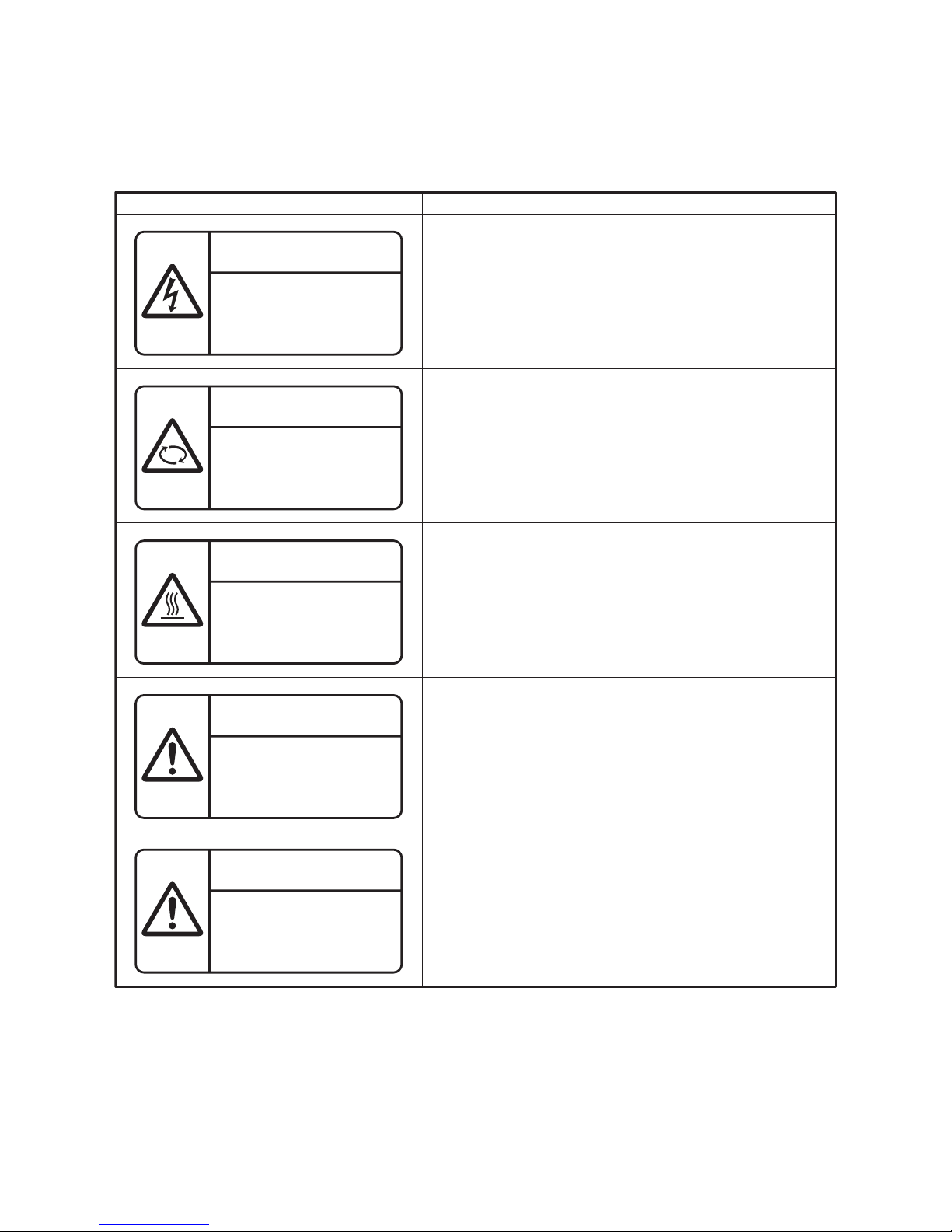
Warning Indications on the Air Conditioner Unit
[Confirmation of warning label on the main unit]
Confirm that labels are indicated on the specified positions
If removing the label during parts replace, stick it as the original.
noi
tpircse
D
noitacidni gninraW
WARNING
ELECTRICAL SHOCK HAZARD
Disconnect all remote electric power supplies before servicing.
WARNING
Moving parts.
Do not operate unit with grille removed.
Stop the unit before the servicing.
CAUTION
High temperature parts.
You might get burned when removing this panel.
CAUTION
Do not touch the aluminium fins of the unit.
Doing so may result in injury.
CAUTION
BURST HAZARD
Open the service valves before the
operation, otherwise there might be
the burst.
WARNING
ELECTRICAL SHOCK HAZARD
Disconnect all remote
electric power supplies
before servicing.
WARNING
Moving parts.
Do not operate unit with grille
removed.
Stop the unit before the servicing.
CAUTION
High temperature parts.
You might get burned
when removing this panel.
CAUTION
Do not touch the aluminum
fins of the unit.
Doing so may result in injury.
CAUTION
BURST HAZARD
Open the service valves before
the operation, otherwise there
might be the burst.
– 6 –
Precaution for Safety
The appliance shall be installed in accordance with national wiring regulations. Capacity shortages of the
power circuit or an incomplete installation may cause an electric shock or fire.
DANGER
Check earth
wires.
Before carrying out the installation, maintenance, repair or removal work, be sure to set the circuit breaker
to the OFF position. Otherwise, electric shocks may result.
Before opening the intake grille of the indoor unit or service panel of the outdoor unit, set the circuit breaker
to the OFF position. Failure to set the circuit breaker to the OFF position may result in electric shocks
through contact with the interior parts.
Only a qualified installer (
∗
1) or qualified service person (∗1) is allowed to remove the intake grille of the
indoor unit or service panel of the outdoor unit and do the work required.
Before opening the electric cover set the circuit breaker to the OFF position. Failure to set the circuit breaker
to the OFF position may result in injury through contact with the rotation parts.
When cleaning the filter or other parts of the indoor unit, set the circuit breaker to OFF without fail, and
place a "Work in progress" sign near the circuit breaker before proceeding with the work.
When you have noticed that some kind of trouble (such as when a check code display has appeared, there
is a smell of burning, abnormal sounds are heard, the air conditioner fails to cool or heat or water is leaking)
has occurred in the air conditioner, do not touch the air conditioner yourself but set the circuit breaker to the
OFF position, and contact a qualified s
ervice person. Take steps to ensure that the power will not be turned
on (by marking "out of service" near the circuit breaker, for instance) until qualified service person arrives.
Continuing to use the air conditioner in the trouble status may cause mechanical problems to escalate or
result in electric shocks or other failure.
Electric
shock
hazard.
Prohibition
When checking the electric parts, removing the cover of the electric parts box of Indoor Unit and/or service
panel of Outdoor Unit inevitably to determine the failure, use gloves to provide protection for electricians,
insulating shoes, clothing to provide protection from electric shock and insulating tools. Be careful not to
touch the live part. Electric shock may result. Only
"Qualified service person" is allowed to do this work.
Do not turn ON the circuit breaker under the condition of removing a cabinet, a panel, etc.
Otherwise, it leads to an electric shock with a high voltage, resulting in loss of life.
– 7 –
WARNING
General
Before starting to repair the air conditioner, read carefully through the Service Manual, and repair the air
conditioner by following its instructions.
Electric
shock
hazard
Prohibition
Only qualified service person (∗1) is allowed to repair the air conditioner. Repair of the air conditioner by
unqualified person may give rise to a fire, electric shocks, injury, water leaks and/or other problems.
Only a qualified installer (∗1) or qualified service person (∗1) is allowed to carry out the electrical work of
the air conditioner. Under no circumstances must this work be done by an unqualified individual since failure
to carry out the work properly may result in electric shocks and/or electrical leaks.
Wear protective gloves and safety work clothing during installation, servicing and removal.
Do not use any refrigerant different from the one specified for complement or replacement.
Otherwise, abnormally high pressure may be generated in the refrigeration cycle, which may result in a
failure or explosion of the product or an injury to your body.
When connecting the electrical wires, repairing the electrical parts or undertaking other electrical jobs, wear
gloves to provide protection for electricians, insulating shoes and clothing to provide protection from electric
shocks. Failure to wear this protective gear may result in electric shocks.
When the air conditioner is to be transported, installed, maintained, repaired or removed, wear protective
gloves and safety work clothing.
To connect the electrical wires, repair the electrical parts or undertake other electrical jobs, wear gloves to
provide protection for electricians, insulating shoes and clothing to provide protection from electric shocks.
Failure to wear this protective gear may result in electric shocks.
Electrical wiring work shall be conducted according to law and regulation in the community and installation
manual. Failure to do so may result in electrocution or short circuit.
Use wiring that meets the specifications in the Installation Manual and the stipulations in the local
regulations and laws. Use of wiring which does not meet the specifications may give rise to electric shocks,
electrical leakage, smoking and/or a fire.
Only a qualified installer (∗1) or qualified service person (∗1) is allowed to undertake work at heights using
a stand of 50 cm or more.
When working at heights, use a ladder which complies with the ISO 14122 standard, and follow the
procedure in the ladder fs instructions. Al so wear a helmet for use in industry as protective gear to
undertake the work.
When working at heights, put a sign in place so that no-one will approach the work location, before
proceeding with the work. Parts and other objects may fall from above, possibly injuring a person below.
When executing address setting, test run, or troubleshooting through the checking window on the electric
parts box, put on insulated gloves to provide protection from electric shock.
Otherwise you may receive an electric shock.
Do not touch the aluminum fin of the outdoor unit. You may injure yourself if you do so.
If the fin must be touched for some reason, first put on protective gloves and safety work clothing, and then
proceed.
Do not climb onto or place objects on top of the outdoor unit.
Yo u may fall or the objects may fall off of the outdoor unit and result in injury.
When transporting the air conditioner, wear shoes with additional protective toe caps.
When transporting the air conditioner, do not take hold of the bands around the packing carton.
Yo u may injure yourself if the bands should break.
Be sure that a heavy unit (10 kg or heavier) such as a compressor is carried by four persons.
This air conditioner has passed the pressure test as specified in IEC 60335-2-40 Annex EE.
When you access inside of the electric cover to repair electric parts, wait for about five minutes after turning
off the breaker. Do not start repairing immediately. Otherwise you may get electric shock by touching
terminals of high-voltage capacitors. Natural discharge of the capacitor takes about five minutes.
Place a gWork in progress h sign near the circuit breaker while the installation, maintenance, repair or
removal work is being carried out. There is a danger of electric shocks if the circuit breaker is set to ON by
mistake.
When checking the electric parts, removing the cover of the electric parts box of Indoor Unit and/ or front
panel of Outdoor Unit inevitably to determine the failure, put a sign gDo not enter h around the site before
the work. Failure to do this may result in third person getting electric shock.
Before operating the air conditioner after having completed the work, check that the electrical parts box
cover of the indoor unit and service panel of the outdoor unit are closed, and set the circuit breaker to the
ON position. You may receive an electric shock if the power is turned on without first conducting these checks.
– 8 –
Stay on
protection
If, in the course of carrying out repairs, it becomes absolutely necessary to check out the electrical parts
with the electrical parts box cover of one or more of the indoor units and the service panel of the outdoor
unit removed in order to find out exactly where the trouble lies, wear insulated heat-resistant gloves,
insulated boots and insulated work overalls
, and take care to avoid touching any live parts. You may receive
an electric shock if you fail to heed this warning.
Only qualified service person (
∗
1) is allowed to do this kind of work.
Check earth
wires.
Use
specified
parts.
Do not bring
a child close
to the
equipment.
Insulating
measures
No fire
Prohibition of
modification.
Before troubleshooting or repair work, check the earth wire is connected to the earth terminals of the main
unit, otherwise an electric shock is caused when a leak occurs. If the earth wire is not correctly connected,
contact an electric engineer for rework.
When any of the electrical parts are to be replaced, ensure that the replacement parts satisfy the
specifications given in the Service Manual (or use the parts contained on the parts list in the
Service Manual). Use of any parts which do not satisfy the required specifications may give rise to electric
shocks, smoking and/or a fire.
Do not modify the products. Do not also disassemble or modify the parts.
It may cause a fire, electric shock or injury.
If, in the course of carrying out repairs, it becomes absolutely necessary to check out the electrical parts
with the electrical parts box cover of one or more of the indoor units and the service panel of the outdoor
unit removed in order to find out exactly where the trouble lies, place
Keep out signs around the work site before proceeding. Third-party individuals may enter the work site and
receive electric shocks if this warning is
not heeded.
Connect the cut-off lead wires with crimp contact, etc., put the closed end side upward and then apply a
water-cut method, otherwise a leak or production of fire is caused at the users' side.
When performing repairs using a gas burner, replace the refrigerant with nitrogen gas because the oil that
coats the pipes may otherwise burn.
When repairing the refrigerating cycle, take the following measures.
1) Be attentive to fire around the cycle.
When using a gas stove, etc., be sure to put out fire before work; otherwise the oil mixed with refrigerant
gas may catch fire.
2) Do not use a welder in the closed room.
When using it without ventilation, carbon monoxide poisoning may be caused.
3) Do not bring inflammables close to the refrigerant cycle, otherwise fire of the welder may catch the
inflammables.
After completing the repair or relocation work, check that the earth wires are connected properly.
Replace components only with parts specified by the manufacturer. Other parts may result in the ignition of
refrigerant in the atmosphere from a leak.
Under no circumstances, the power supply wire or the indoor and outdoor connecting wire must not be
connected in the middle (Connection using a solder less terminal etc.)
Connection trouble in the places where the wire is connected in the middle may give rise to smoking and/or
a fire.
Be sure to connect earth wire. (Grounding work) Incomplete grounding causes an electric shock.
Do not connect earth wires to gas pipes, water pipes, and lightning rods or earth wires for telephone wires.
– 9 –
Refrigerant
This Air Conditioner has adopted a refrigerant HFC R32 or R410A.
Be sure to check the refrigerant type for outdoor unit to be combined. In case that refrigerant type is R32,
this unit uses a flammable refrigerant. If refrigerant leaks and comes in contact with fire or heating part, it
will create harmful gas and there is risk of fire.
Assembly/
Wiring
Check the used refrigerant name and use tools and materials of the parts which match with it.
For the products which use R32 refrigerant, the refrigerant name is indicated at a position on the outdoor
unit where is easy to see. To prevent miss-charging, the route of the service port is changed from one of the
former R22.
Be careful for miss-charging since a charging port of R32 is the same diameter as that of R410A.
Do not use any refrigerant different from the one specified for complement or replacement.
Otherwise, abnormally high pressure may be generated in the refrigeration cycle, which may result in a
failure or explosion of the product or an injury to your body.
Be sure to use the refrigerant (R32 or R410A) specified on the combined outdoor unit.
If different types of refrigerant are mixed, abnormal high pressure generates in the refrigerating cycle and an
injury due to breakage may be caused.
If the different type of refrigerants are mixed in, be sure to recharge the refrigerant
When the air conditioner has been installed or relocated, follow the instructions in the Installation
Manual and purge the air completely so that no gases other than the refrigerant will be mixed in the
refrigerating cycle. Failure to purge the air completely may cause the air conditioner to malfunction.
Do not charge refrigerant additionally.
If charging refrigerant additionally when refrigerant gas leaks, the refrigerant composition in the refrigerating
cycle changes resulted in change of air conditioner characteristics or refrigerant over the specified standard
amount is charged and an abnormal high pressure is applied to the inside of the refrigerating cycle resulted
in cause of breakage or injury. Therefore if the refrigera
nt gas leaks, recover the refrigerant in the air
conditioner, execute vacuuming, and then newly recharge the specified amount of liquid refrigerant. In this
time, never charge the refrigerant over the specified amount.
When recharging the refrigerant in the refrigerating cycle, do not mix the other refrigerant into the specified
refrigerant. If air or others is mixed with the refrigerant, abnormal high pressure generates in the
refrigerating cycle resulted in cause of injury due to breakage.
After the installation work, confirm that refrigerant gas does not leak. If refrigerant gas leaks into the room
and flows near a fire source, such as a cooking range, it may generate noxious gases, causing a fire.
Never recover the refrigerant into the outdoor unit.
When the equipment is moved or repaired, be sure to recover the refrigerant with recovering device.
The refrigerant cannot be recovered in the outdoor unit; otherwise a serious accident such as breakage or
injury is caused.
When the air conditioner has been installed or relocated, follow the instructions in the Installation
Manual and purge the air completely so that no gases other than the refrigerant will be mixed in the
refrigerating cycle. Failure to purge the air completely may cause the air conditioner to malfunction.
After repair work, surely assemble the disassembled parts, and connect and lead the removed wires as
before. Perform the work so that the cabinet or panel does not catch the inner wires.
If incorrect assembly or incorrect wire connection was done, a disaster such as a leak or fire is caused at
user fs side.
Insulator
check
After the work has finished, be sure to use an insulation tester set (500V Megger) to check the resistance is
1MΩ or more between the charge section and the non-charge metal section (Earth position). If the
resistance value is low, a disaster such as a leak or electric shock is caused at user fs side.
Ventilation
When the refrigerant gas leaks during work, execute ventilation.
If the refrigerant gas touches to a fire, it may generate noxious gases, causing a fire.
A case of leakage of the refrigerant and the closed room full with gas is dangerous because a shortage of
oxygen occurs. Be sure to execute ventilation.
If refrigerant gas has leaked during the installation work, ventilate the room immediately.
If the leaked refrigerant gas comes in contact with fire, it may generate noxious gases, causing a fire.
– 10 –
Compulsion
When the refrigerant gas leaks, find up the leaked position and repair it surely.
If the leaked position cannot be found up and the repair work is interrupted, pump-down and tighten the
service valve, otherwise the refrigerant gas may leak into the room.
When gas touches to fire such as fan heater, stove or cocking stove, it may generate noxious gases,
causing a fire though the refriger
ant gas itself is innocuous.
When installing equipment which includes a large amount of charged refrigerant such as a multi air
conditioner in a sub-room, it is necessary that the density does not the limit even if the refrigerant leaks.
If the refrigerant leaks and exceeds the limit density, an accident of shortage of oxygen is caused.
Check after
repair
Do not
operate the
unit with the
valve closed.
Check after
reinstallation
Cooling
check
Tighten the flare nut with a torque wrench in the specified manner.
Excessive tighten of the flare nut may cause a crack in the flare nut after a long period, which may result in
refrigerant leakage.
Nitrogen gas must be used for the airtight test.
The charge hose must be connected in such a way that it is not slack.
For the installation/moving/reinstallation work, follow to the Installation Manual.
If an incorrect installation is done, a trouble of the refrigerating cycle, water leak, electric shock or fire is caused.
Install the outdoor unit properly in a location that is durable enough to support the weight of the outdoor unit.
Insufficient durability may cause the outdoor unit to fall, which may result in injury.
After repair work has finished, check there is no trouble. If check is not executed, a fire, electric shock or
injury may be caused. For a check, turn off the power breaker.
After repair work (installation of front panel and cabinet) has finished, execute a test run to check there is no
generation of smoke or abnormal sound. If check is not executed, a fire or an electric shock is caused.
Before test run, install the front panel and cabinet.
Check the following items after reinstallation.
1) The earth wire is correctly connected.
2) The power cord is not caught in the product.
3) There is no inclination or unsteadiness and the installation is stable.
If check is not executed, a fire, an electric shock or an injury is caused.
When the service panel of the outdoor unit is to be opened in order for the fan motor, reactor, inverter or the
areas around these parts to be repaired immediately after the air conditioner has been shut down, set the
circuit breaker to the OFF position, and then wait at least 10 minutes before opening the service panel.
If you fail to heed this warning, you will run the risk of burning yourself bec
ause the fan motor, reactor,
inverter heat sink and other parts will be very hot to the touch.
In addition, before proceeding with the repair work, wear the kind of insulated heat-resistant gloves
designed to protect electricians.
Be sure to fix the screws back which have been removed for installation or other purposes.
Once the repair work has been completed, check for refrigerant leaks, and check the insulation resistance
and water drainage. Then perform a trial run to check that the air conditioner is running properly.
Check the following matters before a test run after repairing piping.
• Connect the pipes surely and there is no leak of refrigerant.
• The valve is opened.
Running the compressor under condition that the valve closes causes an abnormal high pressure resulted
in damage of the parts of the compressor and etc. and moreover if there is leak of refrigerant at connecting
section of pipes, the air is suctioned and causes further abnormal high pressure resulted in burst or injury.
Only a qualified installer (∗1) or qualified service person (∗1) is allowed to relocate the air conditioner.
It is dangerous for the air conditioner to be relocated by an unqualified individual since a fire, electric shocks,
injury, water leakage, noise and/or vibration may result.
When the service panel of the outdoor unit is to be opened in order for the compressor or the area around
this part to be repaired immediately after the air conditioner has been shut down, set the circuit breaker to
the OFF position, and then wait at least 10 minutes before opening the service panel. If you fail to heed this
warning, you will run the risk of burning yourself because the compress
or pipes and other parts will be very
hot to the touch. In addition, before proceeding with the repair work, wear the kind of insulated heatresistant gloves designed to protect electricians.
Cooling
Take care not to get burned by compressor pipes or other parts when checking the cooling cycle while
running the unit as they get heated while running. Be sure to put on gloves providing protection for heat.
– 11 –
Installation
Only a qualified installer (
∗
1) or qualified service person (∗1) is allowed to install the air conditioner.
If the air conditioner is installed by an unqualified individual, a fire, electric shocks, injury, water leakage,
noise and/or vibration may result.
Compulsion
Before starting to install the air conditioner, read carefully through the Installation Manual, and follow its
instructions to install the air conditioner.
Be sure to use the company-specified products for the separately purchased parts. Use of no specified
products may result in fire, electric shock, water leakage or other failure.
Have the installation performed by a qualified installer.
Do not supply power from the power terminal block equipped on the outdoor unit to another outdoor unit.
Capacity overflow may occur on the terminal block and may result in fire.
Do not install the air conditioner in a location that may be subject to a risk of expire to a combustible gas.
If a combustible gas leaks and becomes concentrated around the unit, a fire may occur.
Install the indoor unit at least 2.5 m above the floor level since otherwise the users may injure themselves or
receive electric shocks if they poke their fingers or other objects into the indoor unit while the air conditioner
is running.
Install a circuit breaker that meets the specifications in the installation manual and the stipulations in the
local regulations and laws.
When transporting the air conditioner, use a forklift and when moving the air conditioner by hand, move the
unit with 4 people.
Install a circuit breaker that meets the specifications in the installation manual and the stipulations in the
local regulations and laws.
Install the circuit breaker where it can be easily accessed by the agent.
If you install the unit in a small room, take appropriate measures to prevent the refrigerant from exceeding
the limit concentration even if it leaks. Consult the dealer from whom you purchased the air conditioner
when you implement the measures. Accumulation of highly concentrated refrigerant may cause an oxygen
deficiency accident.
Do not place any combustion appliance in a place where it is directly exposed to the wind of air
conditioner, otherwise it may cause imperfect combustion.
When removing the welding parts of suction and discharge pipe for the compressor, remove them at the
place ventilated well after recovering the refrigerant. Improper recovering may cause the spurt of the
refrigerant and the refrigeration oil, causing an injury.
When carrying out the pump-down work shut down the compressor before disconnecting the refrigerant pipe.
Disconnecting the refrigerant pipe with the service valve left open and the compressor still operating will
cause air, etc. to be sucked in, raising the pressure inside the refrigeration cycle to an abnormally high level,
and possibly resulting in reputing, injury, etc.
Confirm
When performing the welding work, check whether refrigerant leaks or remains.
If the leakage refrigerant gas touches a fire source, it may generate noxious gases, causing a fire.
Prohibition
Do not vent gases to the atmosphere.
Venting gases to the atmosphere is prohibited by the law.
Wearing of
gloves
Ensure wearing of gloves when performing any work in order to avoid injury from parts, etc.
Failure to wear the proper protective gloves cause an injury due to the parts, etc.
CAUTION

– 12 –
Declaration of Conformity
Manufacturer: TOSHIBA CARRIER CORPORATION
336 Tadehara, Fuji-shi, Shizuoka-ken 416-8521 JAPAN
TCF holder: TOSHIBA CARRIER EUROPE S.A.S
Route de Thil
01120 Montluel FRANCE
Hereby declares that the machinery described below:
Generic Denomination: Air Conditioner
Model / type: Indoor unit
<Slim Duct>
RAV-RM301SDT-E RAV-RM301SDT-TR
RAV-RM401SDT-E RAV-RM401SDT-TR
RAV-RM561SDT-E RAV-RM561SDT-TR
Commercial name: Digital Inverter Series, Super Digital Inverter Series Air Conditioner
Complies with the provisions of the “Machinery” Directive (Directive 2006/42/EC) and the regulations
transposing into national law
NOTE
This declaration becomes invalid if technical or operational modifications are introduced without the
manufacturer’s consent.
Explanations given to user
If you have discovered that the fan grille is damaged, do not approach the outdoor unit but set the circuit
breaker to the OFF position, and contact a qualified service person to have the repairs done.
Do not set the circuit breaker to the ON position until the repairs are completed.
Relocation
• Only a qualified installer (*1) or qualified service person (*1) is allowed to relocate the air conditioner.
It is dangerous for the air conditioner to be relocated by an unqualified individual since a fire, electric shocks,
injury, water leakage, noise and / or vibration may result.
• When carrying out the pump-down work shut down the compressor before disconnecting the refrigerant pipe.
Disconnecting the refrigerant pipe with the service valve left open and the compressor still operating will cause
air, etc. to be sucked in, raising the pressure inside the refrigeration cycle to an abnormally high level, and
possibly resulting in reputing, injury, etc.
(*1) Refer to the “Definition of Qualified Installer or Qualified Service Person”

– 13 –
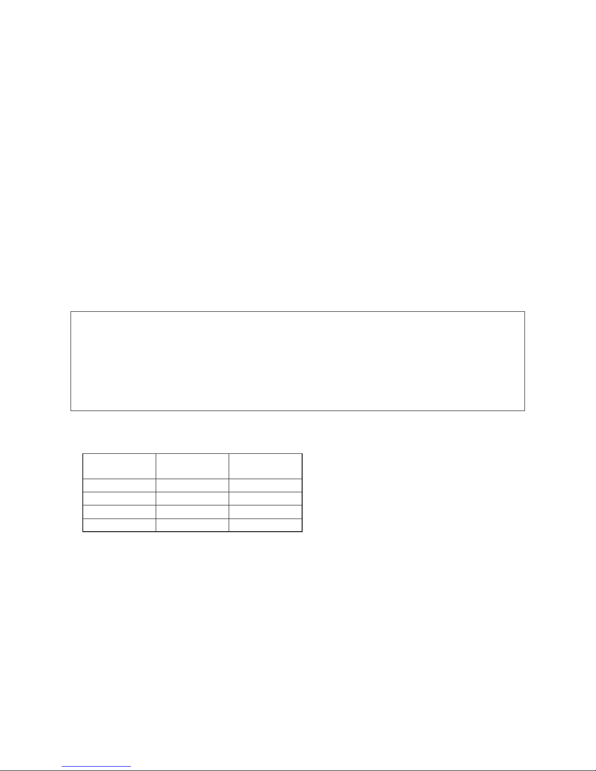
Specifications
∗
: Under 70 (dB(A))
Model
Sound pressure level (dB(A))
Weight (kg)
Cooling Heating
RAV-RM301SDT-E
RAV-RM401SDT-E
RAV-RM561SDT-E
RAV-RM301SDT-TR
RAV-RM401SDT-TR
RAV-RM561SDT-TR
∗
∗
∗
∗
∗
∗
∗
∗
∗
∗
∗
∗
22
22
22
22
22
22

– 14 –
About refrigerant R32
This air conditioner adopts a new HFC type refrigerant (R32) which does not deplete the ozone layer.
1. Safety Caution Concerned to Refrigerant R32
Be sure that water, dust, the former refrigerant or the former refrigerating oil is not mixed into the
refrigerating cycle of the air conditioner with refrigerant R32 during installation work or service work.
If an incorrect work or incorrect service is performed, there is a possibility to cause a serious accident.
Use the tools and materials exclusive to R32 to purpose a safe work.
2. Safety and Cautions on Installation/Service
<Safety items>
When gas concentration and ignition energy are happened at the same time, R32 has a slight possibility of
burning. Although it will not ignite under normal work environment conditions, be aware that the flame
spreads if ignition should occur.
It is necessary to carry out installation/servicing safely while taking the following precautions into
consideration.
1) Never use refrigerant other than specified refrigerant (R32) in an air conditioner which is designed to
operate with the specified refrigerant (R32).
If other refrigerant than R32 is used, it may cause personal injury, etc. by a malfunction, a fire, a rupture.
2) Since R32 is heavier than air, it tends to accumulate on the bottom (near the floor).
Ventilate properly for the working environment to prevent its combustion.
Especially in a basement or a closed room where is the high risk of the accumulation, ventilate the room
with a local exhaust ventilation.
If refrigerant leakage is confirmed in the room or the place where the ventilation is insufficient, do not
work until the proper ventilation is performed and the work environment is improved.
3) When performing brazing work, be sure to check for leakage refrigerant or residual refrigerant.
If the leakage refrigerant comes into contact with fire, a poisonous gas may occur or it may cause a fire.
Keep adequate ventilation during the work.
4) When refrigerant gas leaks during work, execute ventilation. If the leakage refrigerant comes into contact
with a fire, a poisonous gas may occur or it may cause a fire.
5) In places where installing / repairing air-conditioning equipment, etc., keep the source of ignition such as
gas combustion equipment, petroleum combustion equipment, electric heater etc. away. Do not smoke in
the place.
6) When installing or removing an air conditioner, do not mix air in the refrigerant cycle.
If air or others is mixed with the refrigerant, abnormal high pressure generates in the refrigerating cycle,
causing injury due to the breakage.
7) After installation work complete, confirm that refrigerant gas is not leaking on the flare connection part or
others. If leaked refrigerant comes to contact with a fire, toxic gas may occur, causing a fire.
8) Perform the installation work and re-installation according to the installation manual.
Pay attention especially to the area of application. Improper installation may cause refrigeration trouble or
water leakage, electric shock and fire etc.
9) Unauthorized modifications to the air conditioner may be dangerous. If a breakdown occurs please call a
qualified air conditioner technician or electrician.
Improper repair may result in water leakage, electric shock and fire, etc.
10) Carry out the airtight test with nitrogen at a specified pressure. Do not use oxygen or acetylene gas
absolutely as it may cause an explosion.
11) Always carry a refrigerant leakage detection sensor during the work and work while checking that no
refrigerant leaks around working environment.
12) If the leakage refrigerant comes into contact with fire, it may cause a fire.
Have a dry powder or CO2 fire extinguisher adjacent to the charging area.
– 15 –
<Caution items>
1) The opposite side dimension of the air-conditioner’s flared nut using R32 and the shape of the charge
port are the same as those of R410A.
2) Be careful not to charge refrigerant by mistake. Should the different type of refrigerant mix in, be sure to
recharge the refrigerant
3) Do not mix the other refrigerant or refrigerating oil with the refrigerant.
4) Since the pressure of R32 is high 1.6 times of that of the former refrigerant (R22), use tools and parts
with high pressure withstand specification similar to R410A.
5) In the installation time, use clean pipe materials and work with great attention so that water and others do
not mix in because pipes are affected by impurities such as water, oxide film, oil, etc. Use the clean pipes.
Be sure to braze while flowing nitrogen gas in the pipe. (Never use gas other than nitrogen gas.)
6) For the earth protection, use a vacuum pump for air purge.
7) R32 refrigerant is Single-component refrigerant that does not change its composition.
Although it is possible to charge the refrigerant with either liquid or gas, charge it with liquid.
(If using gas for charging, composition of the refrigerant changes and then characteristics of the air
conditioner change.)
3. Pipe Materials
For the refrigerant pipes, copper pipe and joints are mainly used.
It is necessary to select the most appropriate pipes to conform to the standard.
Use clean material in which impurities adhere inside of pipe or joint to a minimum.
1) Copper pipe
Be sure to select the pipes with copper thickness in the table below since the pressure of an air conditioner
using R32 is higher than that of R22.
2) Joint
The flare joint and socket joint are used for joints of the copper pipe.
The joints are rarely used for installation of the air conditioner.
However clear impurities when using them.
<Piping>
The pipe thickness, flare finishing size, flare nut and others differ according to a refrigerant type.
When using a long copper pipe for R32, it is recommended to select “Copper or copper-base pipe without
seam” and one with bonded oil amount 40mg/10m or less.
Also do not use crushed, deformed, discolored (especially inside) pipes.
(Impurities cause clogging of expansion valves and capillary tubes.)
<Flare nut>
Use the flare nuts which are attached to the air conditioner unit.
Nominal
diameter
Outer
diameter (mm)
Thickness (mm)
R410A or R32
1/2
3/8
1/2
5/8
Make sure not to use a thin copper
pipe such as 0.7 mm copper
thickness in the market.
6.4
9.5
12.7
15.9
0.80
0.80
0.80
1.00
– 16 –
4. Tools
Tools exclusive for R410A (The following tools for R410A are required.)
Note 1 When flaring is carried out for R410A or R32 using the conventional flare tools, adjustment of
projection margin is necessary. For this adjustment, a copper pipe gauge, etc. are necessary.
Note 2 When saturation temperature is described, the gauge manifold differs for R410A and R32.
If saturation temperature reading is required, special tools exclusive for R32 are required.
Note 3 Since R32 has a slight possibility of burning, be sure to use the tools corresponding to R32.
Note 4 Like R410, a Vacuum pump adapter needs installing to prevent a Vacuum pump oil (mineral oil) from
flowing backward into the Charge hose. Mixing of the Vacuum pump oil into R32 refrigerant may cause
a trouble such as generation of sludge, clogging of capillary, etc.
Note 5 Be sure to use those tools after confirming they correspond to each refrigerant.
Note 6 For a refrigerant cylinder exclusive for R32, the paint color (or label color) of the cylinder is set to the
specified color (light blue) together with the indication of the refrigerant name.
Note 7 Although the container specification is the same as R410A, use a recovering container exclusive for
R32 to avoid mixing with other refrigerants.
Note 8 Be careful for miss-charging of the refrigerant during work. Miss-charging of the refrigerant type may
cause not only damage of the equipments but also a fire etc.
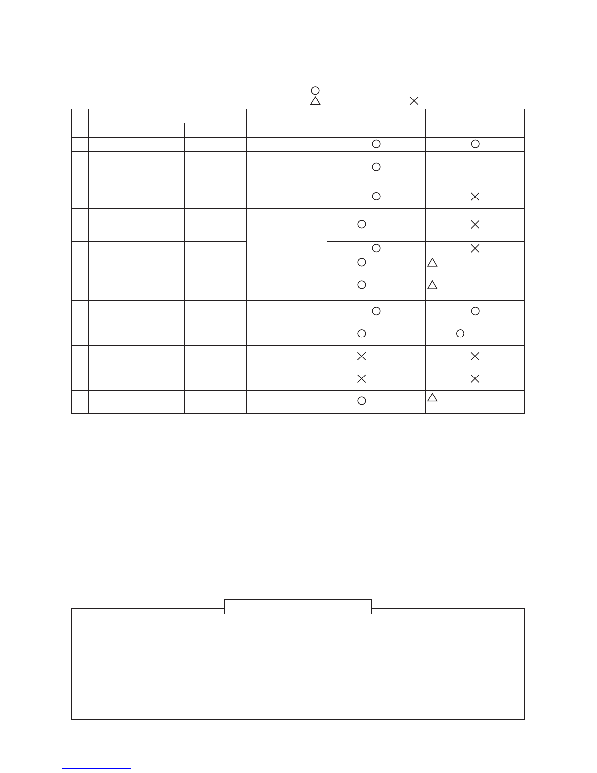
: R410A tools available
: Partly unavailable, : R410A tools unavailable
No.
Installation/service tools
Tools / Equipment specification
1Flare tool Clutch type Pipe flaring
Use
Applicability to R32 air
conditioner or not
Applicability to R22 air
conditioner or not
5Charge hose High-voltage
3 Torque wrench —
Tightening of
flare nut
6Vacuum pump —
Vacuum
drying
Note 3
1/2"-20UNF(5/16" Flare)
Connection diameter
1/4"
7Vacuum pump adapter —
Vacuum
drying
Note 4
1/2"-20UNF(5/16" Flare)
Connection diameter
1/4"
8
Electronic balance for
refrigerant charging
For 10 kg or
20 kg cylinder
Refrigerant
charge
9Leakage detector —
Gas leakage
check
Note 5
Note 5
10 Refrigerant cylinder —
Refrigerant
charge
Note 6
11
Refrigerant recovery
cylinder
Exclusive for
R32
Refrigerant
recovery container
Note 7
12
Refrigerant recovery
device
—
Refrigerant
recovery device
Note 8
Connection diameter
1/4"
4Gauge manifold
Por t size
1/2"-20UNF
(5/16" Flare)
Evacuating,
refrigerant
charge, run
check, etc.
Note 2
2
Copper pipe gauge for
adjusting projection
margin
——
Flaring by
conventional
flare tool
In addition to the above exclusive tools, the following equipments are necessary as the general tools.
General tools
1) Pipe cutter 6) Spanner or Monkey wrench
2) Reamer 7) Hole core drill
3) Pipe bender 8) Tape measure
4) Level vial 9) Metal saw
5) Screwdriver (+, –)
Also prepare the following equipments for other installation method and run check.
1) Clamp meter 3) Insulation resistance tester (Megger)
2) Thermometer 4) Electroscope

– 17 –
About refrigerant R410A
This air conditioner adopts a HFC type refrigerant (R410A) which does not deplete the ozone layer.
1. Safety Caution Concerned to R410A Refrigerant
The pressure of R410A is high 1.6 times of that of the former refrigerant (R22).
Accompanied with change of refrigerant, the refrigerating oil has been also changed.
Therefore, be sure that water, dust, the former refrigerant or the former refrigerating oil is not mixed into the
refrigerating cycle of the air conditioner with R410A refrigerant during installation work or service work.
If an incorrect work or incorrect service is performed, there is a possibility to cause a serious accident.
Use the tools and materials exclusive to R410A to purpose a safe work.
2. Cautions on Installation/Service
<Piping>
The pipe thickness, flare finishing size, flare nut and others differ according to a refrigerant type.
When using a long copper pipe for R410A, it is recommended to select “Copper or copper-base pipe without
seam” and one with bonded oil amount 40mg/10m or less.
Also do not use crushed, deformed, discolored (especially inside) pipes.
(Impurities cause clogging of expansion valves and capillary tubes.)
<Flare nut>
Use the flare nuts which are attached to the air conditioner unit.
1) Do not mix the other refrigerant or refrigerating oil.
For the tools exclusive to R410A, shapes of all the joints including the service port differ from those of
the former refrigerant in order to prevent mixture of them.
2) As the use pressure of the R410A refrigerant is high, use material thickness of the pipe and tools which
are specified for R410A.
3) In the installation time, use clean pipe materials and work with great attention so that water and others
do not mix in because pipes are affected by impurities such as water, oxide scales, oil, etc.
Use the clean pipes.
Be sure to brazing with flowing nitrogen gas. (Never use gas other than nitrogen gas.)
4) For the earth protection, use a vacuum pump for air purge.
5) R410A refrigerant is azeotropic mixture type refrigerant.
Therefore use liquid type to charge the refrigerant. (If using gas for charging, composition of the
refrigerant changes and then characteristics of the air conditioner change.)
3. Pipe Materials
For the refrigerant pipes, copper pipe and joints are mainly used.
It is necessary to select the most appropriate pipes to conform to the standard.
Use clean material in which impurities adhere inside of pipe or joint to a minimum.
1) Copper pipe
2) Joint
The flare joint and socket joint are used for joints of the copper pipe.
The joints are rarely used for installation of the air conditioner. However clear impurities when using
them.
– 18 –
4. Tools
1. Required Tools for R410A
Mixing of different types of oil may cause a trouble such as generation of sludge, clogging of capillary, etc.
Accordingly, the tools to be used are classified into the following three types.
1) Tools exclusive for R410A (Those which cannot be used for conventional refrigerant (R22))
2) Tools exclusive for R410A, but can be also used for conventional refrigerant (R22)
3) Tools commonly used for R410A and for conventional refrigerant (R22)
The table below shows the tools exclusive for R410A and their interchangeability.
Tools exclusive for R410A (The following tools for R410A are required.)
Tools whose specifications are changed for R410A and their interchangeability
(Note) When flaring is carried out for R410A using the conventional flare tools, adjustment of projection
margin is necessary. For this adjustment, a copper pipe gauge, etc. are necessary.
General tools (Conventional tools can be used.)
In addition to the above exclusive tools, the following equipments which serve also for R22 are necessary
as the general tools.
1) Vacuum pump. Use vacuum pump by attaching vacuum pump adapter.
hcnerw yeknoM ro rennapS)8hcnerw euqroT)2
llird eroc eloH)9rettuc epiP)3
)mm4 edis etisoppO( hcnerw nogaxeH)01remaeR)4
erusaem epaT)11redneb epiP)5
was lateM)21laiv leveL)6
7) Screwdriver (+, –)
Also prepare the following equipments for other installation method and run check.
)reggeM( retset ecnatsiser noitalusnI)3retem pmalC)1
epocsortcelE)4retemomrehT)2
No. Used tool
Flare tool
Copper pipe gauge for
adjusting projection margin
Torque wrench
Gauge manifold
Charge hose
Vacuum pump adapter
Electronic balance for
refrigerant charging
Refrigerant cylinder
Leakage detector
Usage
Pipe flaring
Flaring by conventional
flare tool
Tightening of flare nut
Evacuating, refrigerant
charge, run check, etc.
Vacuum evacuating
Refrigerant charge
Refrigerant charge
Gas leakage check
R410A
air conditioner installation
Existence of Whether conven-
new equipment tional equipment
for R410A can be used
Ye s ∗ (Note)
Ye s ∗ (Note)
Ye s N o
Ye s N o
Ye s N o
Ye s Ye s
Ye s N o
Ye s N o
Conventional air
conditioner installation
Whether conventional
equipment can be used
Ye s
∗ (Note)
No
No
Ye s
Ye s
No
Ye s
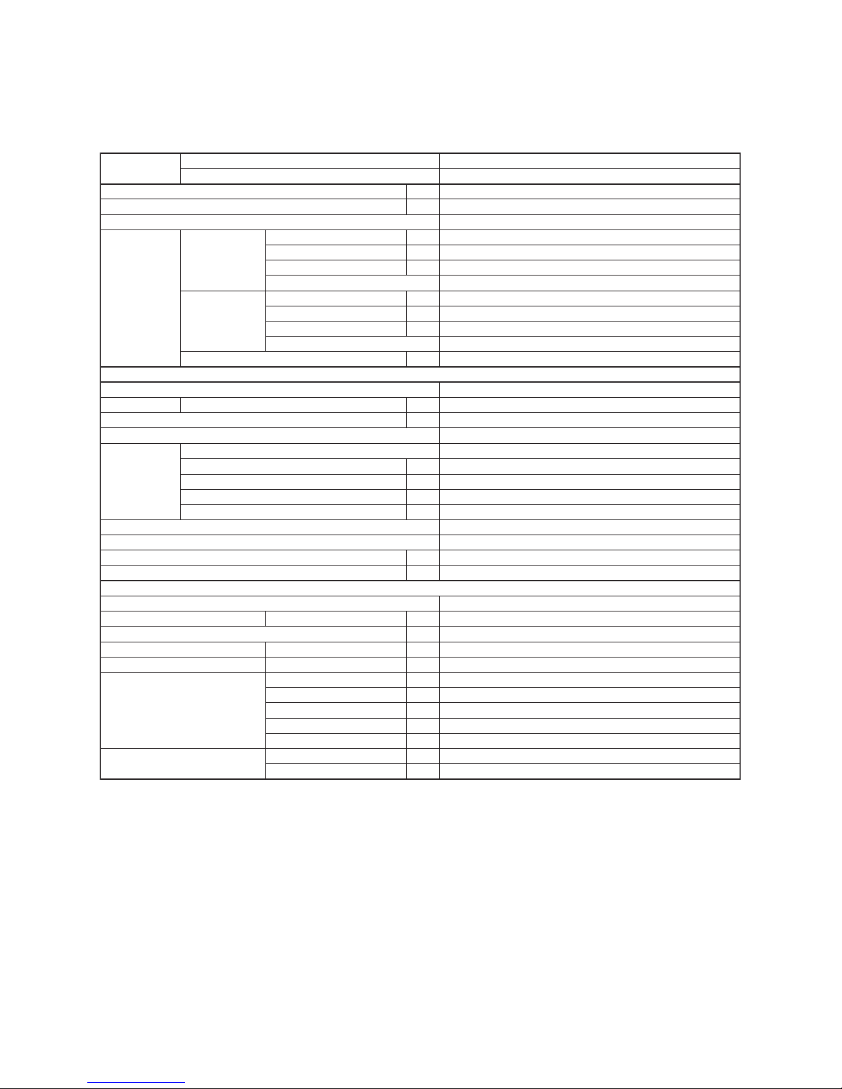
– 19 –
1. SPECIFICATIONS
SDI combination (R32)
<Single type>
Model name
Indoor Unit RAV-RM
RAV-GP
561SDT-E
561ATP-E
Appearance Zinc hot dipping steel plate
210 × 845 × 645
22
Finned tube
Centrifugal
780 (678 / 582)
60
29
4 - 14 - 29 - 44
Standard filter (Long life filter)
VP25 (Polyvinyl chloride tube)
45 (40 / 36)
55 (53 / 48)
Air filter
Drain port (Nominal dia. mm)
Electrical
charastaristics
Cooling Running current A
Sound puressure level Cooling/Heating dB(A)
Sound power level Cooling/Heating dB(A)
Pipe connections Gas / Liquid mm
Min. Length m
Operation Range Cooling ˚C
Heating ˚C
Max. Length m
Charge less m
Max. height difference m
Weight kg
Outer dimension H × W × D mm
Refrigarant ( Type / Charge weight (kg) ) R32 / 1.35
630 x 799 x 299
45
46 / 48
63 / 65
12.7 / 6.4
3
50
20
30
-15 to 52
-27 to 15
Sound pressure level High ( M+ / L+ ) (factory default) dB(A)
Sound power level High ( M+ / L+ ) (factory default) (2*) dB(A)
Standard air flow ( M / L ) m³/h
Motor
External static pressure (factory default)
External static pressure range
Pa
Pa
W
Fan unit Fan
Heat exchanger
Outer dimension H × W × D mm
Weight kg
Power consumption kW
Power factor %
EER
Heating Running current A
Maximum current
Indoor Unit
Outdoor Unit
Power consumption kW
Power factor %
COP
Cooling capacity (Rated (Min.-Max.)) (*1) kW 5.0 (1.2 - 5.6)
5.6 (0.9 - 7.0)
1phase 50Hz 230V (220V-240V)
7.57 - 6.94
1.56
93
3.21
7.81 - 7.15
1.58
93
3.54
13.1
Heating capacity (Rated (Min.-Max.)) (*1) kW
Power supply
Outdoor Unit
A
*1 : The cooling capacity, heating capacity and electrical characteristics are measured under the conditions
specified by JIS B8615-1 based on the reference piping. The reference piping consists of 5m of main
piping and 2.5m of branch piping connected with 0 meter height.
*2 : The sound level are measured in an anechoic chamber in accordance with JIS B 8616. Normally, the
values measured in the actual operation environment become larger than the indicated values due to the
effects of external sound.
Notes ;
Rated conditions Cooling : Indoor air temperature 27°C DB / 19 °C WB, Outdoor air temperature 35°C DB
Heating : Indoor air temperature 20°C DB, Outdoor air temperature 7°C DB / 6 °C WB
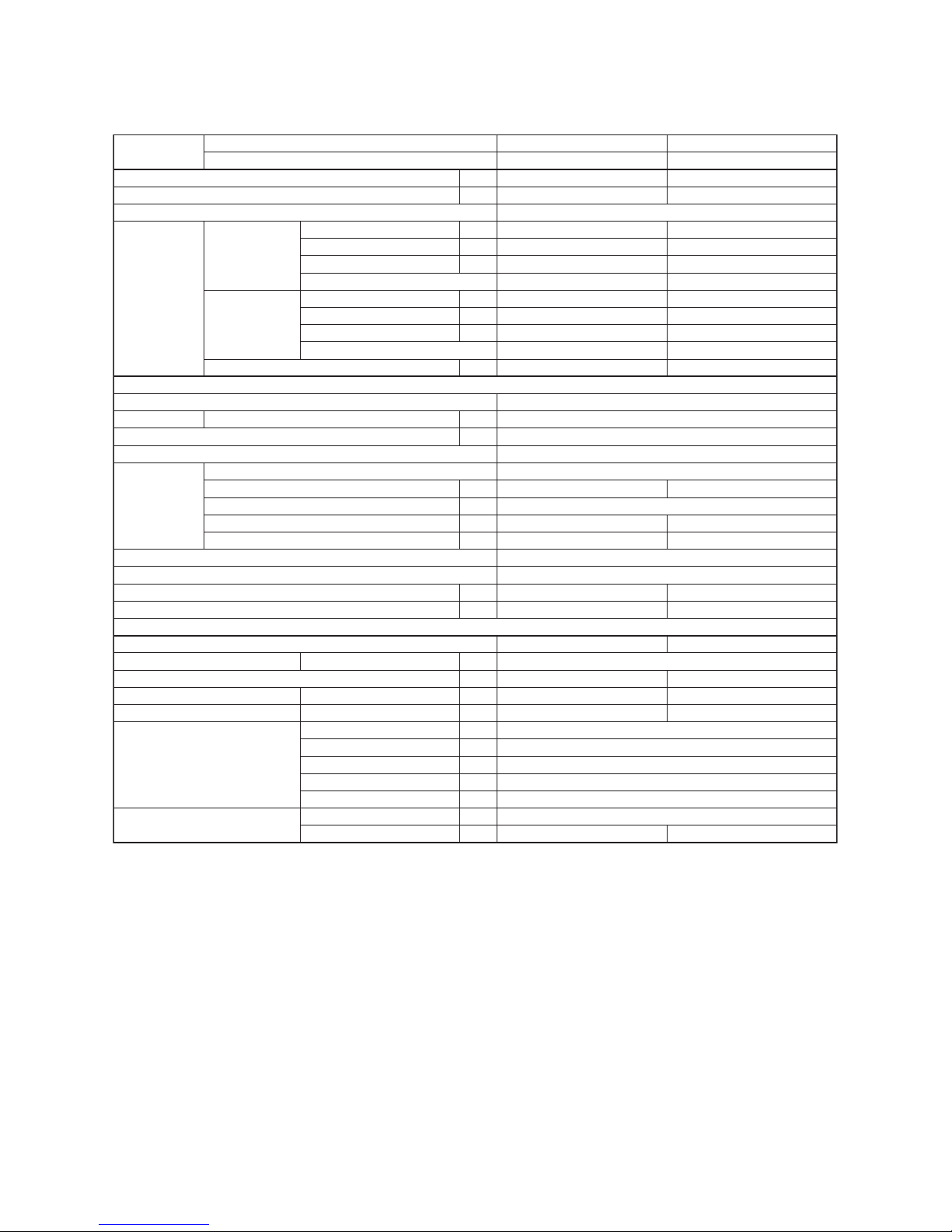
– 20 –
SDI combination (R410A)
<Single type>
Model name
Indoor Unit RAV-RM
RAV-SP
401SDT-E
404ATP-E
561SDT-E
564ATP-E
Appearance Zinc hot dipping steel plate
210 × 845 × 645
22
Finned tube
Centrifugal
60
Standard filter (Long life filter)
VP25 (Polyvinyl chloride tube)
Air filter
Drain port (Nominal dia. mm)
Electrical
charastaristics
Cooling Running current A
Sound puressure level Cooling/Heating dB(A)
Sound power level Cooling/Heating dB(A)
Pipe connections Gas / Liquid mm
Min. Length m
Operation Range Cooling ˚C
Heating ˚C
Max. Length m
Charge less m
Max. height difference m
Weight kg
Outer dimension H × W × D mm
Refrigarant ( Type / Charge weight (kg) ) R410A / 1.0
40
45 / 47
62 / 64
-15 to 15
550 x 780 x 290
12.7 / 6.4
5
30
20
30
-15 to 43
R410A / 1.4
44
47 / 48
63 / 64
-20 to 15
Sound pressure level High ( M+ / L+ ) (factory default) dB(A)
Sound power level High ( M+ / L+ ) (factory default) (2*) dB(A)
Standard air flow ( M / L ) m³/h
Motor
External static pressure (factory default)
External static pressure range
Pa
Pa
W
Fan unit Fan
690 (600 / 522)
30
5 - 15 - 30 - 45
39 (36 / 33)
52 (48 / 44)
780 (678 / 582)
29
4 - 14 - 29 - 44
45 (40 / 36)
55 (53 / 48)
1phase 50Hz 230V (220V-240V)
5.20 - 4.77
1.03
90
3.50
4.94 - 4.53
1.00
92
4.00
15.0
7.24 - 6.63
1.56
98
3.21
6.68 - 6.12
1.44
98
3.89
13.6
Heat exchanger
Outer dimension H × W × D mm
Weight kg
Power consumption kW
Power factor %
EER
Heating Running current A
Maximum current
Indoor Unit
Outdoor Unit
Power consumption kW
Power factor %
COP
Cooling capacity (Rated (Min.-Max.)) (*1) kW 3.6 (1.5 -4.0)
4.0 (1.5 - 5.0)
5.0 (1.2 - 5.6)
5.6 (0.9 -7.4)
Heating capacity (Rated (Min.-Max.)) (*1) kW
Power supply
Outdoor Unit
A
*1 : The cooling capacity, heating capacity and electrical characteristics are measured under the conditions
specified by JIS B8615-1 based on the reference piping. The reference piping consists of 5m of main
piping and 2.5m of branch piping connected with 0 meter height.
*2 : The sound level are measured in an anechoic chamber in accordance with JIS B 8616. Normally, the
values measured in the actual operation environment become larger than the indicated values due to the
effects of external sound.
Notes ;
Rated conditions Cooling : Indoor air temperature 27°C DB / 19 °C WB, Outdoor air temperature 35°C DB
Heating : Indoor air temperature 20°C DB, Outdoor air temperature 7°C DB / 6 °C WB
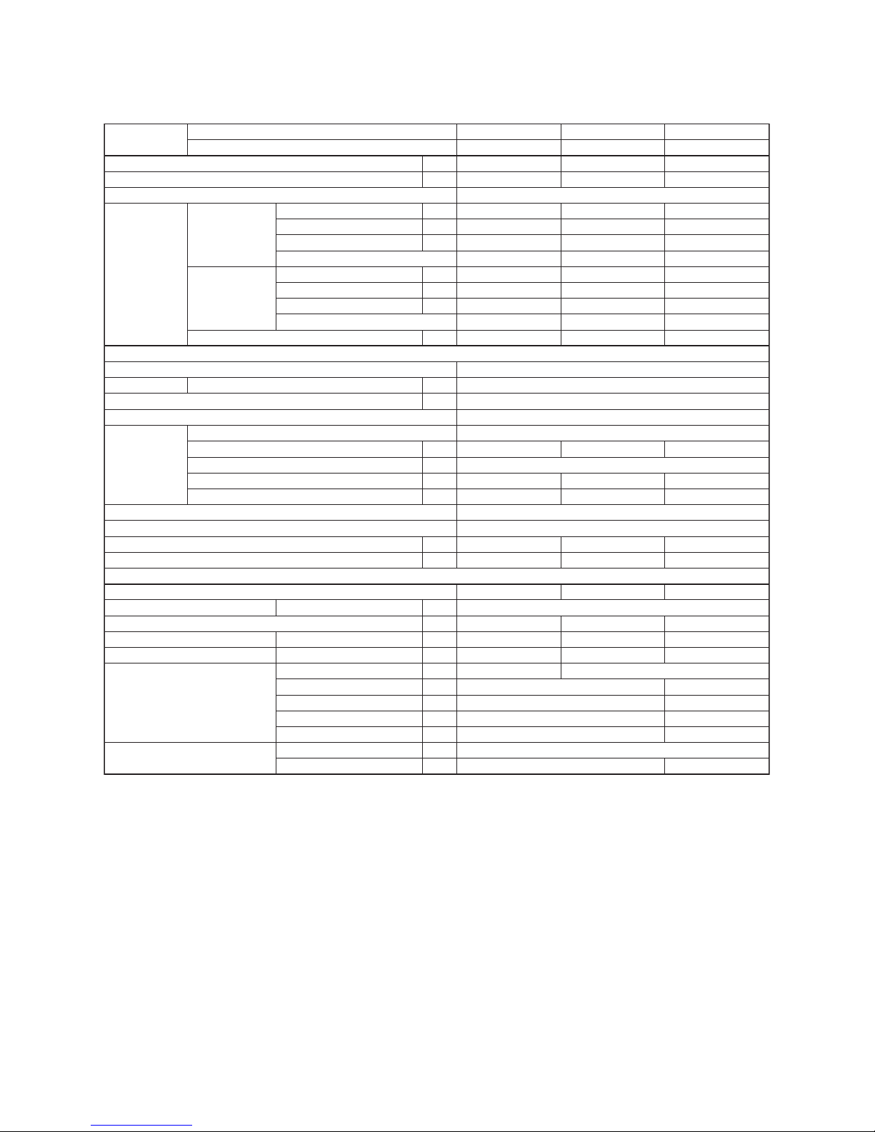
– 21 –
DI combination (R410A)
<Single type>
*1 : The cooling capacity, heating capacity and electrical characteristics are measured under the conditions
specified by JIS B8615-1 based on the reference piping. The reference piping consists of 5m of main
piping and 2.5m of branch piping connected with 0 meter height.
*2 : The sound level are measured in an anechoic chamber in accordance with JIS B 8616. Normally, the
values measured in the actual operation environment become larger than the indicated values due to the
effects of external sound.
Model name
Indoor Unit RAV-RM
RAV-SM
301SDT-E
304ATP-E
561SDT-E
564ATP-E
Appearance Zinc hot dipping steel plate
210 × 845 × 645
22
Finned tube
Centrifugal
690 (600 / 522)
60
30
5 - 15 - 30 - 45
Standard filter (Long life filter)
VP25 (Polyvinyl chloride tube)
39 (36 / 33)
52 (48 / 44)
Air filter
Drain port (Nominal dia. mm)
Electrical
charastaristics
Cooling Running current A
Sound puressure level Cooling/Heating dB(A)
Sound power level Cooling/Heating dB(A)
Pipe connections Gas / Liquid mm
Min. Length m
Operation Range Cooling ˚C
Heating ˚C
Max. Length m
Charge less m
Max. height difference m
Weight kg
Outer dimension H × W × D mm
Refrigarant ( Type / Charge weight (kg) ) R410A / 0.8
33
46 / 47
61 / 62
9.5 / 6.4
R410A / 1.4
550 x 780 x 290
39
49 / 50
64 / 65
-15 to 46
R410A / 1.1
40
46 / 48
63 / 65
5
30
20
30
-15 to 15
12.7 / 6.4
2
20
15
10
-15 to 24
Sound pressure level High ( M+ / L+ ) (factory default) dB(A)
Sound power level High ( M+ / L+ ) (factory default) (2*) dB(A)
Standard air flow ( M / L ) m³/h
Motor
External static pressure (factory default)
External static pressure range
Pa
Pa
W
Fan unit Fan
660 (560 / 480)
30
5 - 15 - 30 - 45
39 (36 / 33)
51 (48 / 44)
780 (678 / 582)
29
4 - 14 - 29 - 44
45 (40 / 36)
55 (53 / 48)
Heat exchanger
Outer dimension H × W × D mm
Weight kg
Power consumption kW
Power factor %
EER
Heating Running current A
Maximum current
Indoor Unit
Outdoor Unit
Power consumption kW
Power factor %
COP
Cooling capacity (Rated (Min.-Max.)) (*1) kW 2.5 (0.9 - 3.0)
3.4 (0.8 - 4.5)
2.82 - 2.60
0.56
90
4.46
4.20 - 3.85
0.86
93
3.95
7.85
5.0 (1.5 - 5.6)
5.3 (1.5 - 6.3)
8.95 - 8.20
1.91
97
2.62
7.03 - 6.44
1.50
97
3.53
12.9
401SDT-E
404ATP-E
3.6 (0.9 - 4.0)
4.0 (0.8 - 5.0)
1phase 50Hz 230V (220V-240V)
4.20 - 4.60
0.93
92
3.87
4.35 - 4.75
0.97
93
4.12
9.15
Heating capacity (Rated (Min.-Max.)) (*1) kW
Power supply
Outdoor Unit
A
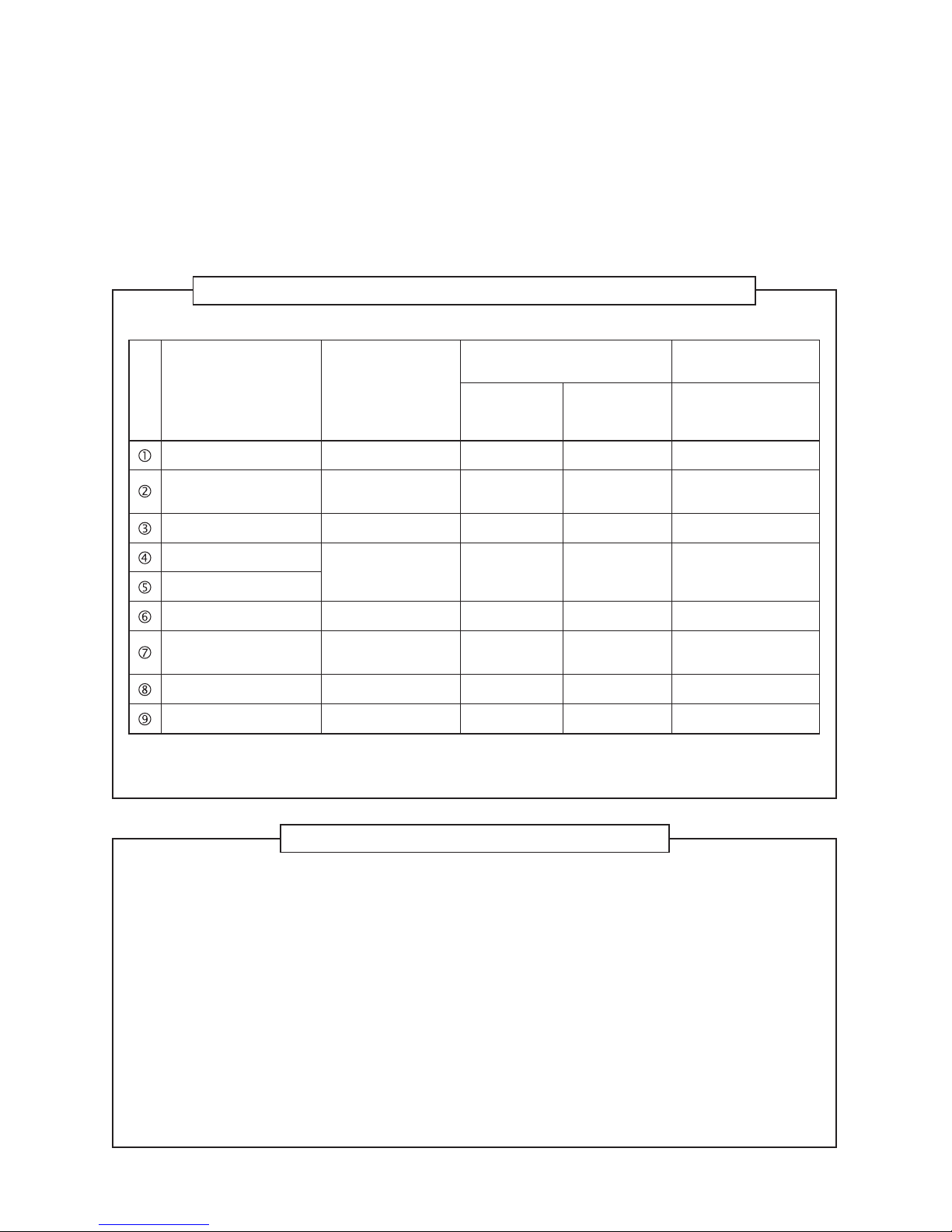
– 22 –
No
Outdoor
unit type
Connection
type
HP
Indoor unit Outdoor unit Rated Capacity (kW) Specifications
1 SDI Single 2.0 RAV-RM561SDT-E 1 RAV-GP561ATP-E 1 5.0 5.6 5.77 A+ 5.0 4.20 A+ 3.8
Model name Qty Model name Qty Cooling Heating SEER
Energy
Label
Pdesign
C
SCOP
(average)
Energy
Label
Pdesign
h
(average)
No
Outdoor
unit type
Connection
type
HP
Indoor unit Outdoor unit Rated Capacity (kW) Specifications
1
2
3
4
5
DI
DI
DI
SDI
SDI
Single
Single
Single
Single
Single
1.0
1.5
2.0
1.5
2.0
RAV-RM301SDT-E
RAV-RM401SDT-E
RAV-RM561SDT-E
RAV-RM401SDT-E
RAV-RM561SDT-E
1
1
1
1
1
RAV-SM304ATP-E
RAV-SM404ATP-E
RAV-SM564ATP-E
RAV-SP404ATP-E
RAV-SP564ATP-E
1
1
1
1
1
2.5
3.6
5.0
3.6
5.0
3.4
4.0
5.3
4.0
5.6
6.10
5.55
5.06
5.11
5.10
A++
A
B
A
A
2.5
3.6
5.0
3.6
5.0
4.48
3.88
4.06
3.90
3.83
A+
A
A+
A
A
2.9
3.7
4.4
3.8
5.4
Model name Qty Model name Qty Cooling Heating SEER
Energy
Label
Pdesign
C
SCOP
(average)
Energy
Label
Pdesign
h
(average)
Specifications for ErP Lot-10
Slim Duct <Series 1>
Refrigerant : R32
Refrigerant : R410A
– 23 –
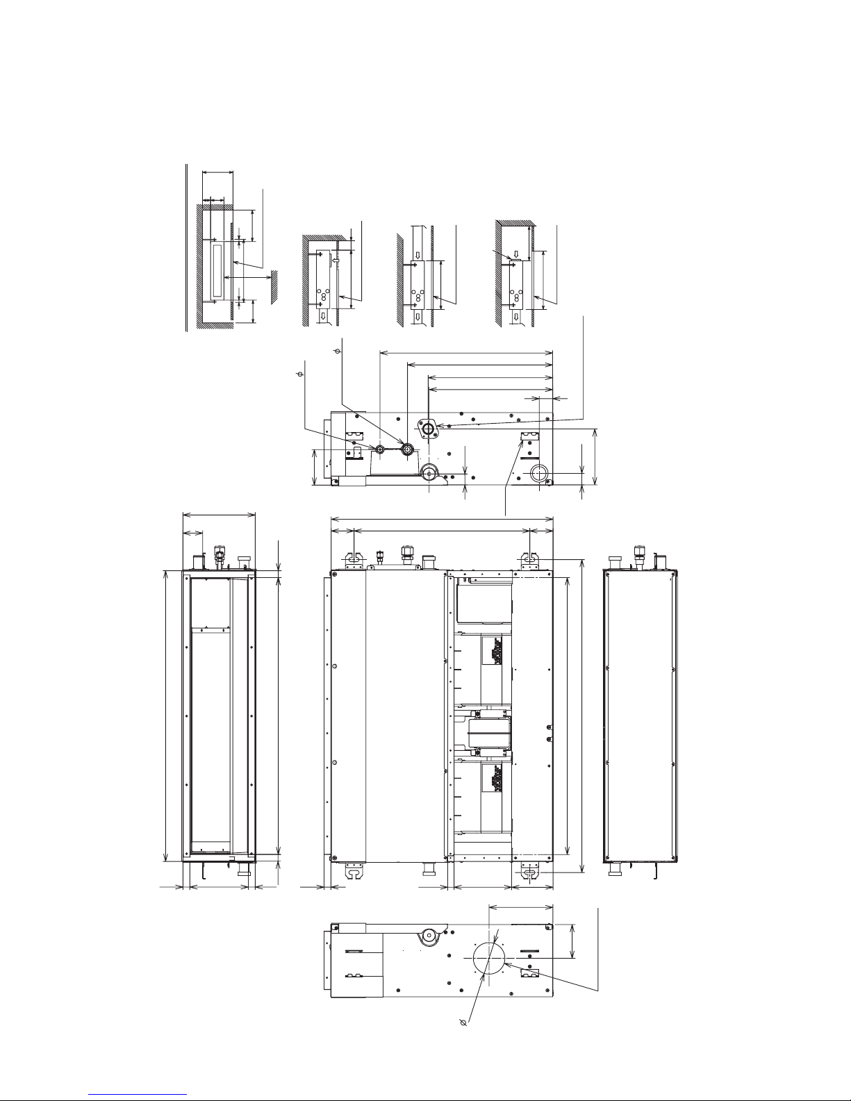
210
57
645
67 67
168
120
Hanging bolt pitch 910
805
Unit external dimension 845
168(inside)
803(inside)
21
103
163
502
422
372
40
33
31
359
Hanging bolt pitch 511
Refrigerant pipe
connecting port 6.4
Refrigerant pipe
connecting port 9.5
(Gas side)
(Liquid side)
Hung-up
185.4
98.2
plate
Drain pipe connecting port
21
21
20
21
19
Space required for installation and servicing
Air outlet
5 or more
210
235
50
945
50
250 or
more
100 or
more
or more
2500
Ceiling
Service door (Ceiling opening)
or more
Floor surface
50 or more
645
Ceiling
Air inlet
645
Ceiling
Air inlet
Service door (Ceiling opening)
Ceiling
Air inlet
745
300 or more
Service door (Ceiling opening)
Air inlet
Service door (Ceiling opening)
(VP25)
9
2
Auxiliary fresh air flange
Knockout for
(Unit:mm)
2. CONSTRUCTION VIEWS (EXTERNAL VIEWS)
2-1. RAV-RM301SDT*
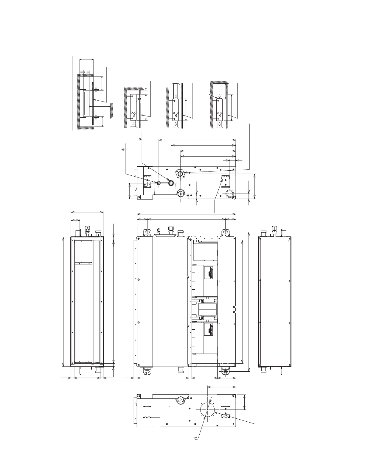
– 24 –
2-2. RAV-RM401SDT*, RM561SDT*
210
57
645
67 67
168
120
Hanging bolt pitch 910
805
Unit external dimension 845
168(inside)
803(inside)
21
103
163
502
422
372
40
33
31
359
Hanging bolt pitch 511
Refrigerant pipe
connecting port 6.4
Refrigerant pipe
connecting port 12.7
(Gas side)
(Liquid side)
Hung-up
plate
Drain pipe connecting port
21
21
20
21
19
Space required for installation and servicing
Air outlet
5 or more
210
235
50
945
50
250 or
more
100 or
more
or more
2500
Ceiling
Service door (Ceiling opening)
or more
Floor surface
50 or more
645
Ceiling
Air inlet
645
Ceiling
Air inlet
Service door (Ceiling opening)
Ceiling
Air inlet
745
300 or more
Service door (Ceiling opening)
Air inlet
Service door (Ceiling opening)
(VP25)
98.2
Auxiliary fresh air flange
Knockout for
185.4
9
2
(Unit:mm)
– 25 –
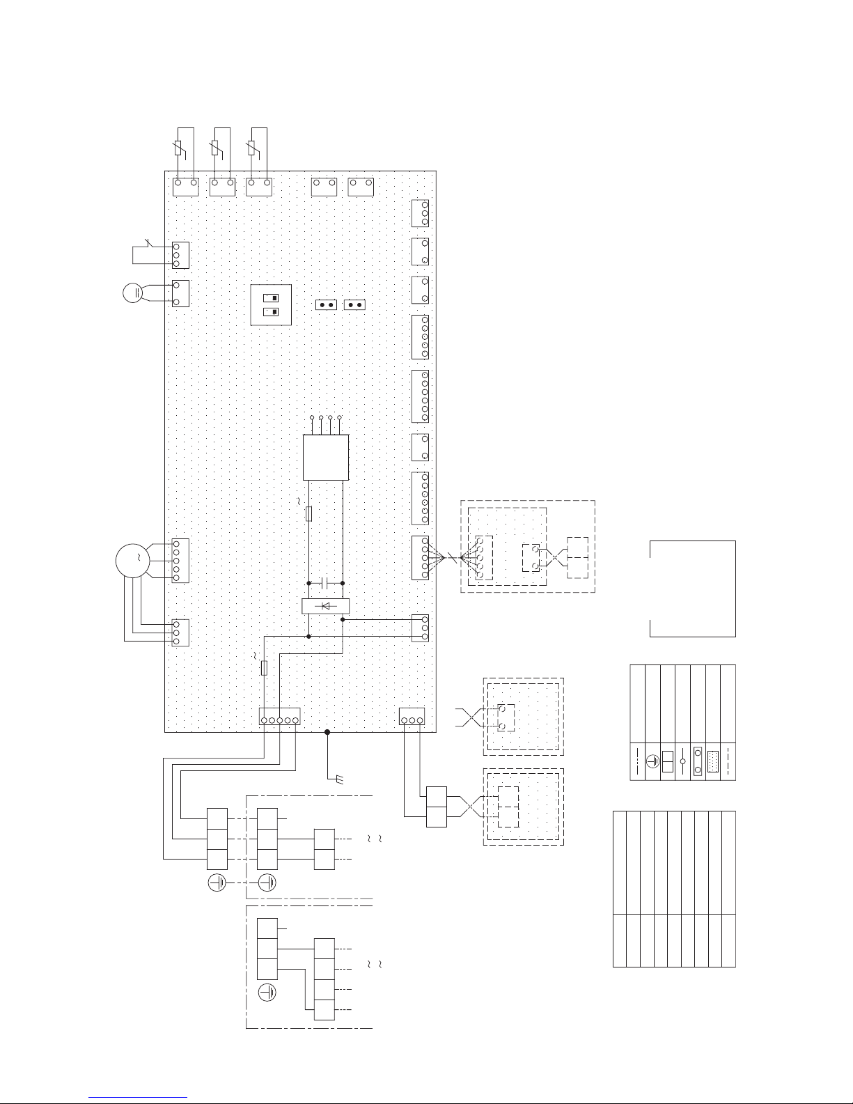
3. WIRING DIAGRAMS
"1:1 Model"
Connection
Interface
(Sold separately)
CN334
(WHT)
1
CN41
TA
Indoor temp sensor
TB01,02
TC,TCJ
Temp sensor
Terminal Block
F01,02
Symbol
DM
Drain Pump Motor
Fan Motor
Float Switch
FM
FS
Fuse
Connector
Parts Name
CN**
Wired Remote
Controller
(Sold separately)
Adapter for
Wireless Remote
Controller
(Sold separately)
A
B
TB02
BA
BLK
BLK
BLK
WHT
2
1
3
CN309
(BLU)
(YEL)
WHT
Power supply
220V 60Hz
220-240V 50Hz
BLU : BLUE
BLK : BLACK
L
1
WHT : WHITE
YEL : YELLOW
RED : RED
COLOR
INDICATION
1
TB01
RED
3
BLK
N
Earth
Outdoor unit
Serial
signal
32
(WHT)
CN66
CN67
P01
5
(BLK)
Indoor unit
Earth screw
32
BLK
1
T6.3A
250V
F01
1
(RED)(WHT)
CN20
CN60
(WHT)
(YEL)
CN50
(WHT)
CN61
(WHT)
(BLU)
21
U3
MCC-1440
U4
2
CN51
CN40
1
(RED)
(BLU)
4
3
5
23
1
1
5
3 4 5 321
FAN DRIVE
4 5 6 21 4321 65 5431 2 1
EXCT
122
Control P.C. Board
for Indoor Unit
MCC-1570
F02
T3.15A
-
+
+
250V
DC 7V
Power
supply
circuit
CN32
DC20V
DC15V
DC12V
21
3
2
(WHT)
CN333
3 45
ON
CN70
(DISP)CN72
CN73
(External static
(CHK)CN71
21
(YEL)
CN104
CN101
(BLK)
(RED)
CN102
SW501
2
CN504
(WHT)
1
31
CN34
(RED)
1
1
2
t°
2
t°
TC
TCJ
2
t°
1
TA
3
MS
FM
DM
FS
1 32
CN80
(GRN)
CN508
(RED)
2
1
GRN : GREEN
screw
Power supply
380V 3N 60Hz
380-415V 3N 50Hz
L2
1
L3
Earth
Outdoor unit
Serial
signal
32
screw
N
P.C.Board
Connector
Terminal
Terminal Block
Protection Ground
Field Wiring
Accessory
pressure setup)
2
1
M
L1
– 26 –
4. PARTS RATING
Indoor unit
Model RAV-
RM30
∗
RM40
∗
RM56
∗
Fan motor
Float switch
Drain pump motor
TA sensor
TC sensor
TCJ sensor
SWF-280-60-3
FS-0218-102
MDP-1401
Lead wire length: 328 mm Vinyl tube
Ø6 size lead wire length: 1200 mm Vinyl tube (Black)
Ø6 size lead wire length: 1200 mm Vinyl tube (Red)
– 27 –
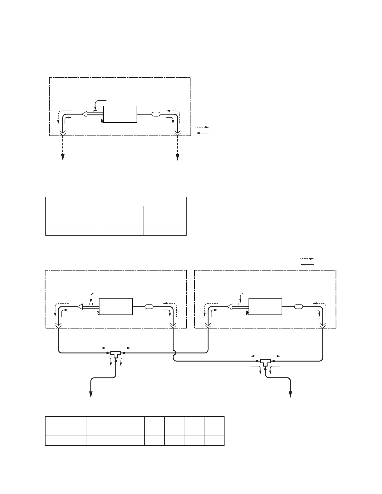
(Indoor unit A)
Liquid side
(Outer dia : ØA)
Liquid side
(Outer dia : ØC)
Gas side
(Outer dia : ØB)
Distributor
(Strainer incorporated)
Strainer
TCJ sensor
TC sensor
Heat
exchanger
To outdoor unit
Branch pipe
(Indoor unit B)
Liquid side
(Outer dia : ØA)
Liquid side
(Outer dia : ØD)
Gas side
(Outer dia : ØB)
Distributor
(Strainer incorporated)
Strainer
TCJ sensor
TC sensor
To outdoor unit
Branch pipe
Heat
exchanger
Heating
Cooling
Indoor unit
RM40 × 2
RM56 × 2
Branch pipe
RBC-TWP30E2
RBC-TWP30E2
ABCD
6.4 12.7 9.5 15.9
6.4 12.7 9.5 15.9
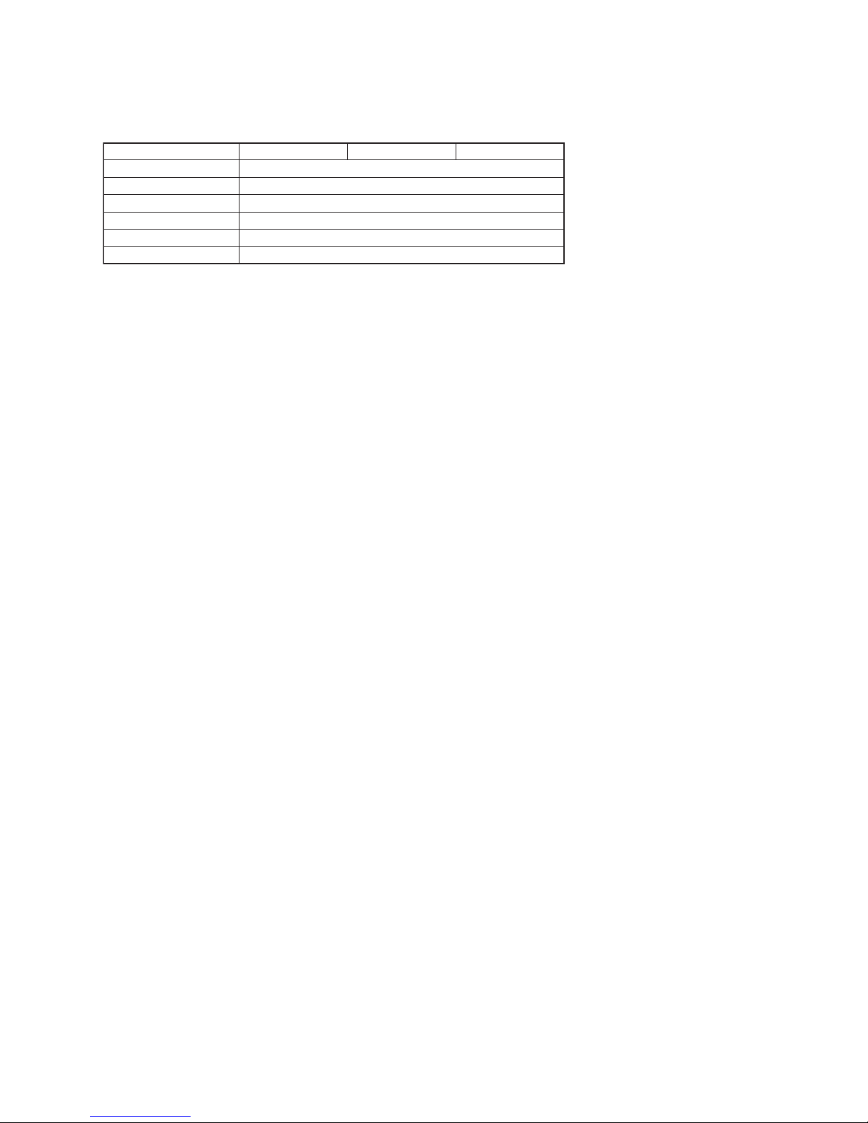
5. SYSTEMATIC REFRIGERATING CYCLE DIAGRAM
5-1. Indoor Unit
• Single type (Combination of 1 indoor unit and 1 outdoor unit)
Dimension table
• Twin type (Combination of 2 indoor units and 1 outdoor unit)
(Indoor unit)
Liquid side
(Outer dia : ØB)
Gas side
(Outer dia : ØA)
Distributor
(Strainer incorporated)
Strainer
Heating
Cooling
TCJ sensor
TC sensor
Heat
exchanger
To outdoor unit
To outdoor unit
Indoor unit
RM30 type
Outer diameter of refrigerant pipe
Gas side ØA Liquid side ØB
9.5 6.4
RM40, 56 type
12.7 6.4
– 28 –
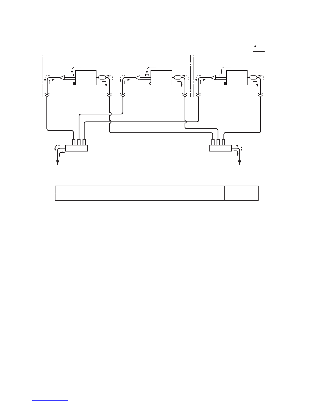
• Triple type (3 indoor units and 1 outdoor unit)
Heating
Cooling
(Indoor unit A)
Distributor
(with strainer)
Distributor
(with strainer)
Distributor
(with strainer)
Strainer Strainer Strainer
Heat
exchanger
Heat
exchanger
Heat
exchanger
TCJ sensor TCJ sensor TCJ sensor
TC sensor
Branch pipe Branch pipe
To outdoor unit To outdoor unit
Liquid-side
(outer diameter:
Ø
C)
Gas-side
(outer diameter: ØD)
TC sensor TC sensor
Liquid-side
(outer diameter: ØA)
Liquid-side
(outer diameter: ØA)
Liquid-side
(outer diameter: ØA)
Gas-side
(outer diameter: ØB)
Gas-side
(outer diameter: ØB)
Gas-side
(outer diameter: ØB)
(Indoor unit B) (Indoor unit C)
Dimension table
Indoor unit Branch pipe A B C D
RM56 × 3 RBC-TRP100E 6.4 12.7 9.5 15.9
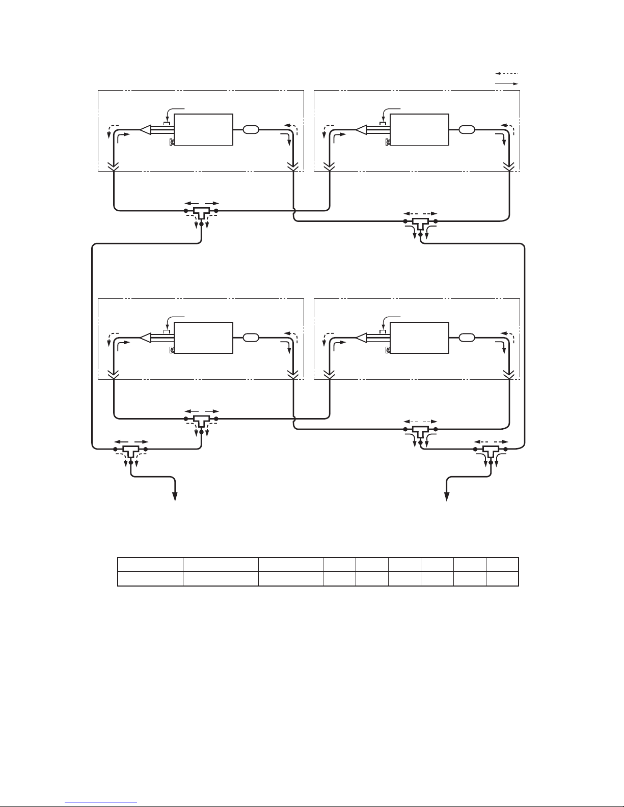
– 29 –
• Double-twin type (4 indoor units and 1 outdoor unit)
Heating
Cooling
(Indoor unit A)
(Indoor unit C)
(Indoor unit B)
(Indoor unit D)
Distributor
(with strainer)
Distributor
(with strainer)
Distributor
(with strainer)
Distributor
(with strainer)
Strainer
Strainer
Strainer
Strainer
Heat exchanger
Heat exchanger
Heat exchanger
Heat exchanger
TCJ sensor
TCJ sensor
TCJ sensor
TCJ sensor
TC sensor
TC sensor
TC sensor
TC sensor
Branch pipe 1
Branch pipe 1
Branch pipe 1
Branch pipe 1
Branch pipe 2
Branch pipe 2
Gas-side
(outer diameter: Ø
D)
To outdoor unit To outdoor unit
Liquid-side
(outer diameter: ØC)
Gas-side
(outer diameter: ØD)
Liquid-side
(outer diameter: ØE)
Gas-side
(outer diameter: ØF)
Liquid-side
(outer diameter: ØA)
Liquid-side
(outer diameter: ØA)
Liquid-side
(outer diameter: ØA)
Liquid-side
(outer diameter: Ø
C)
Liquid-side
(outer diameter: ØA)
Gas-side
(outer diameter: ØB)
Gas-side
(outer diameter: ØB)
Gas-side
(outer diameter: ØB)
Gas-side
(outer diameter: ØB)
Dimension table
Indoor unit Branch pipe 1 Branch pipe 2 ABCDE F
RM56 × 4 RBC-TWP30E2x2 RBC-TWP101E 6.4 12.7 9.5 15.9 12.7 28.6
 Loading...