

Toshiba RAV-DXC010 Installation Manual
For commercial use
RAV-DXC010
LC DX Interfa ce
LC DX Interface
Installation manual
Model name:
ENGLISH
1
LC DX Interface
Installation Manual
This Air Conditioner is a type which adopts a HFC refrigerant (R410A) instead of the conventional
refrigerant R22 in order to prevent destruction of the ozone layer.
This appliance is for commercial us e only and should not be accessible to the g ener al publ i c.
This appliance is not intended for us e by person (including children) wi th r educed physical, sensory
Children should be supervi sed to ens ur e that they do not play with the appliance.
Contents
1
SUPPLIED PARTS
……………..……………………
2
2
PRECAUTIONS FOR SAFETY
……………………………
2 3 INSTALLATION
…………………………………….
3 4 ELECTRICAL WORK
…………………………………
7 5 APPLICABLE CONTROLS
………................................
11 6 TEST RUN
…………………………………….....
17 7 TROUBLE SHOOTING
………...................................
18 8 OPTIONAL PARTS
…………………………………..
21 9 DECLARATION OF CONFORMITY
………………………....
22
10
SERVICE PARTS
……………………………………
23
Please read this Installation Manual carefully before installing the LC DX interface.
• This Manual describes the inst all ati o n method of the LC DX interface.
• You must also refer to the Ins tal l ati on Manual attached to the Toshiba outdoor uni t.
• Please follow the manual(s) for your Air Handling Unit (local supply).
• Toshiba Carrier UK (Ltd) does not take any responsibility on the local design.
ADOPTION OF R410A REFRIGERANT
or mental capabilities, or l ac k of ex per i ence and k nowledge, unless they have been g iv en
supervision or instruction conc er ning use of the appliance by a person r es ponsi bl e for their s afety.
This symbol mark is for EU countries only.
This symbol mark is according to the directive 2002/96/EC Article 10 Information for users and
Annex IV.
This product is designed and manufactured with high quality materials and components which can
be recycled and reused.
This symbol means that electrical and electronic equipment, at the end-of-life, should be disposed
of separately from your household waste.
Please dispose of this equipment at your local community waste collection / recycling centre.
In the European Union there are separate collection systems for used electrical and electronic
product.
2
LC DX Interface
Installation Manual
Refrigerant (R410A) Air Conditioner Installation
To Disconnect the Appliance from Main Power Supply
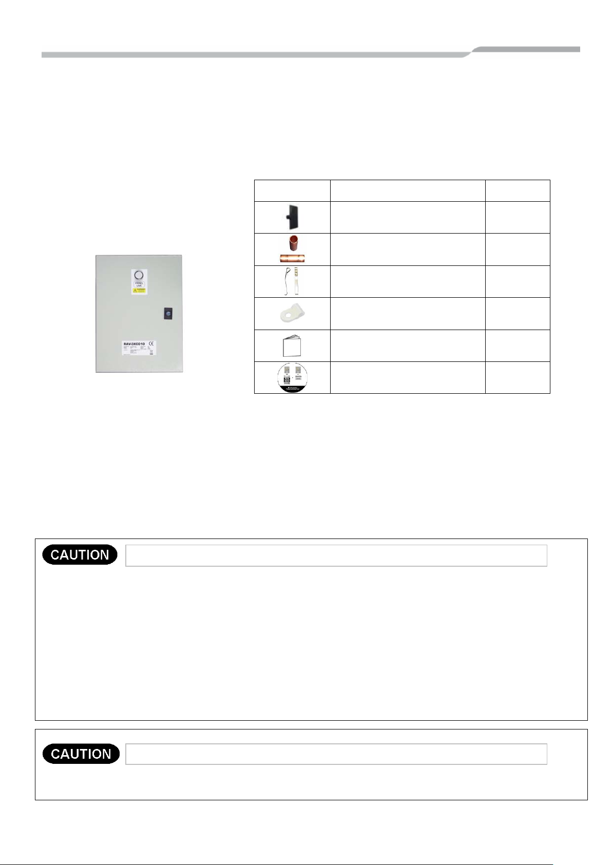
1 SUPPLIED PARTS
The LC DX Interface is designed to allow the connection of a third party air handling unit (with R410A DX
Coil) to a Toshiba LC outdoor unit (DI / SDI / DI-Big).
The Interface consists of a LC DX Controller, including sensors (TC, TCJ and TA), and accessories that
include parts which the installer needs to assemble (including brazing).
LC DX Interface
Item Description Qty
RAV-DXC010
Panel Door Key 1
Sensor Holder 2
Fix Plate 2
P Clamp (TA) 1
Installation manual (English) 1
IM Mult i -Language CD 1
2 PRECAUTIONS FOR SAFETY
• Ensure that all Local, National and International regulations are satisfied.
• Read this “PRECAUTIONS FOR SAFETY” carefully before installation.
• The precautions described below include the important items regarding safety. Observe them without fail.
• After the installation work, perform a trial operation to check for any problem.
• Follow the installation manual to explain how to use and maintain the unit to the customer.
• Turn off the main power supply switch (or breaker) before the unit maintenance.
• Ask the customer to keep the installation manual.
• THIS AIR CONDITIONER ADOPTS THE HFC REFRIGERANT (R410A) WHICH DOES NOT DESTROY OZONE
LAYER.
The characteristics of R410A refrigerant are; easy to absorb water, oxidizing membrane or oil, and its pressure is
approx. 1.6 times higher than that of refrigerant R22. Accompanied with the new refrigerant, refrigerating oil has also
been changed. Therefore, during installation work, be sure that water, dust, former refrigerant, or refrigerating oil does
not enter the refrigerating cycle.
To prevent charging an incorrect refrigerant and refrigerating oil, the sizes of connecting sections of charging port of
the main unit and installation tools are changed from those of conventional refrigerant.
Accordingly the exclusive tools are required for the new refrigerant (R410A).
For connecting pipes, use new and clean piping designed for R410A, and please care so that water or dust does not
enter. Moreover, do not use the existing piping because there are problems with the pressure-resistance force and
impurity in it.
This appliance must be connected to the main power supply by means of a switch with a constant separation of at least
3mm.
3
LC DX Interface
Installation Manual
Size
Standard
Min.
Max.
Rated.
Rated
RAV-
5.0 SM
5.0 SP
5.6 SM
5.6 SP
SM563AT-E
SP564AT-E
6.7 SM
7.1 SP
8.0 SM
8.0 SP
SM803AT-E
SP804ATP-E
10.0 SM
10.0 SP
11.2 SM
11.2 SP
SM1103AT-E1
SP1104AT8-E
12.1 SM
12.5 SP
13.4 SM
14.0 SP
SM1403AT-E1
SP1404AT8-E
14.0 SM
14.0 SP
16.0 SM
16.0 SP
SM1603AT-E
SP1604AT8-E
20.0 SM
-
22.4 SM
-
SM2244AT8-E
-
23.0 SM
-
27.0 SM
-
SM2804AT8-E
-
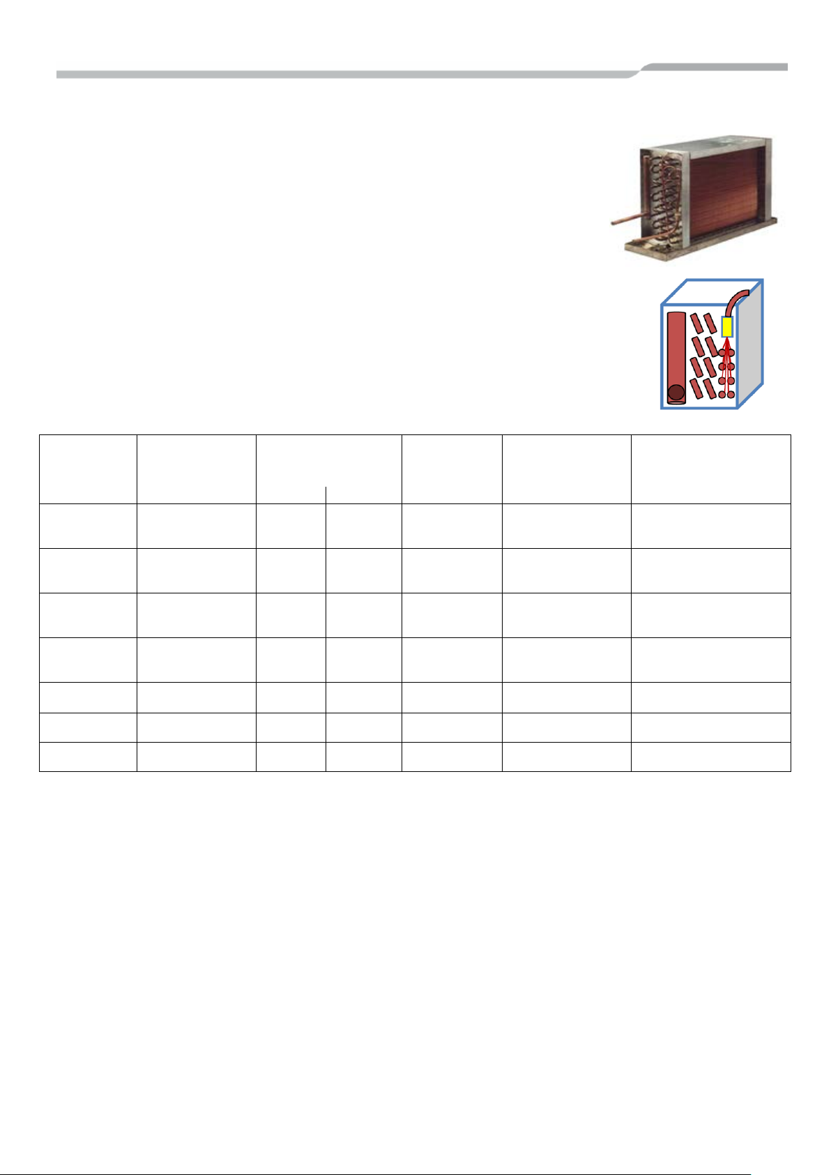
3 INSTALLATION
Use the following information to specify the appropriate AHU and DX Coil for each
outdoor unit. The DX Coil design should be optimised for Cooling (Rated) Condition:-
• The DX Coil must be suitable for R410A.
• The counter flow principle must be observed.
• The design should allow operation as both an Evaporator and a Condenser
• (Features: Multiple circuits / Liquid Capillary Distributor / Gas Header).
• A Drain Pan must be fitted (even if only used in Heat mode) due to defrost cycles.
• It is recommended to fit droplet eliminator plates in the discharge air stream if
used in Cool mode.
• The sensor holders must be brazed on to DX coil to ensure accurate temperature sensing.
• Cooling (Rated): Saturated Suction Temp. (Evaporating Temp.): 7°C
• Heating (Rated): Saturated Discharge Temp. (Condensing Temp.): 44°C
• Target Suction Super Heat: 5K
• System Maximum Operating Pressure: 4.15MPa
• DX Coil must satisfy Burst Pressure: More than 12.45MPa (3 times Maximum Operating Pressure)
AHU
Air Volume
(m3/hr)
Coil Internal
Volume
3
)
(dm
Cooling
Capacity
(kW)
Heating
Capacity
(kW)
DI / DI-Big (SM)
SDI (SP)
2HP 900 0.8 1.1
3HP 1320 1.0 1.4
4HP 1600 1.5 2.1
5HP 2100 1.7 2.7
6HP 2800 1.7 3.2
8HP 3600 3.0 4.2
10HP 4200 3.0 5.4
• The standard air volume flowrate is a guideline. Required capacity should be used for system matching.
• AHU fan motor must be interlocke d to fan contr ol outp ut.
• Maximum DX-Coil U-pipe Outer Diameter: 12.7mm (1/2”)
• Recommended DX-Coil U-pipe Outer Diameter: 9.52mm (3/8”)
• Cooling & Heating output figures are based on calculations and ‘general’ test data. All figures are to be taken as approximations .
The properties of the third party DX Coil will have an affect on the performance of the outdoor units. All capacity data shown is
based on the following Rated Conditions: -
5.0 SP
7.1 SP
10.0 SP
12.5 SP
5.6 SP
8.0 SP
11.2 SP
14.0 SP
SP564AT-E
SP804AT-E
SP1104AT-E
SP1404AT-E
o Cooling (Rated): Indoor air temperature 27°C db / 19°C wb, Outdoor air temperature 35°C db
o Heating (Rated): Indoor air temperature 20°C db, Outdoor air temperature 7°C db / 6°C wb
4
LC DX Interface
Installation Manual
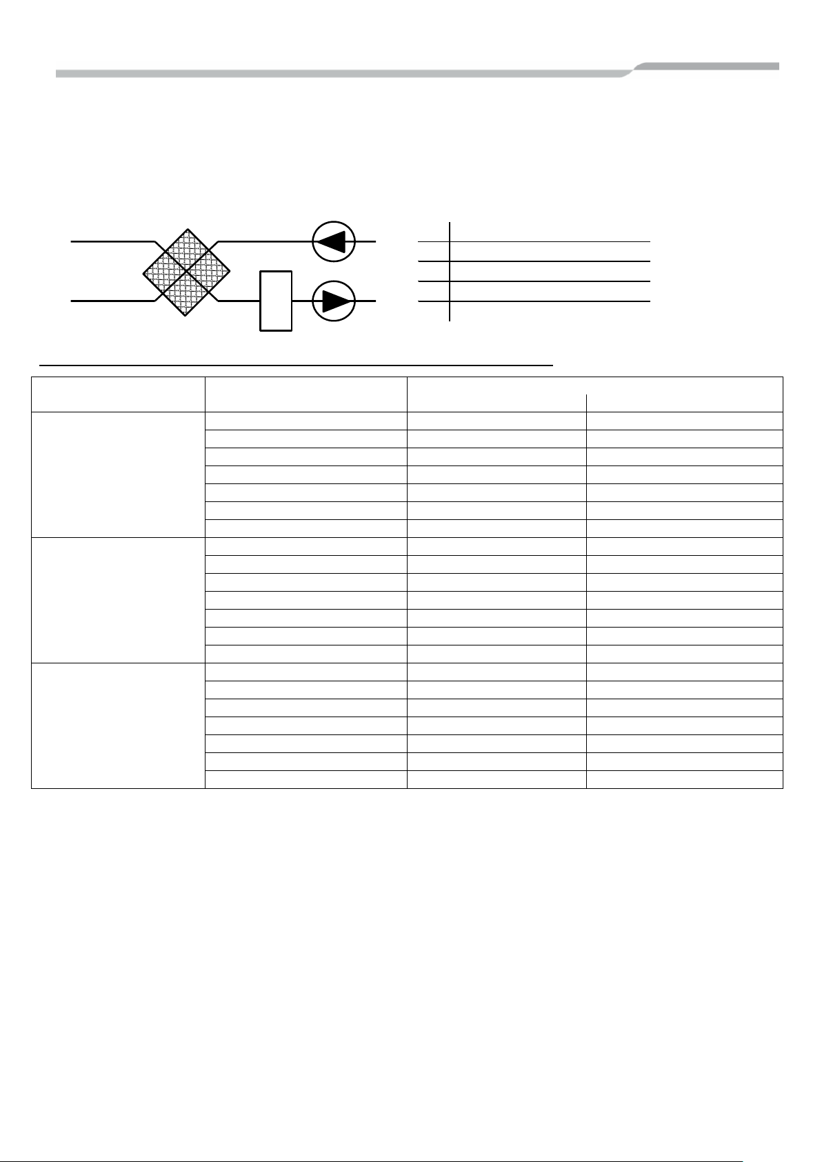
EA
SA
EA
Exhaust Air
OA
Outdoor Air
OA
RA
SA
Supply Air
Heat Recovery
Exchanger
DX COIL
CA
Coil Air (After Heat Recovery Exchanger)
CARAReturn Air
U-Pipe
HP
No. of Circuits
Diameter
Min
Max
2 2 3 3 3 5 4 4 7 5 5 8 6 6 10 8 8
12
10
10
14
2 2 2 3 3 3 4 3 5 5 4 6 6 5 7 8 6
10
10 8 12
2 1 1 3 2 2 4 2 3 5 3 3 6 3 4 8 4 6 10 5 7
Design Conditions for customers DX Coil
• The DX-Coil MUST be operated within the following limits to ensure reliability:-
o Cooling mode DX coil “air on” temp: Min: 15°CWB (18°CDB) ~ Max: 24°CWB (32°CDB)
o Heating mode DX coil “air on” temp: Min: 15°CDB ~ Max: 28°CDB
• When used for Ventilation, the DX-Coil MUST be combined with other equipment such as heat recovery exchanger or heaters /
coolers to ensure that the CA limits are not exceeded:-
Recommended No. of Ref. Circuit by DX-Coil U-Pipe Dia. and DX Coil Size (HP)
8.00
9.52
12.70
IP65
If the wiring is properly carried out by a specialist according to the local regulations, the device fulfills the protection class
IP65.
Automatic Mode
Please be aware that frequent mode changes could occur when using Automatic mode
5
LC DX Interface
Installation Manual
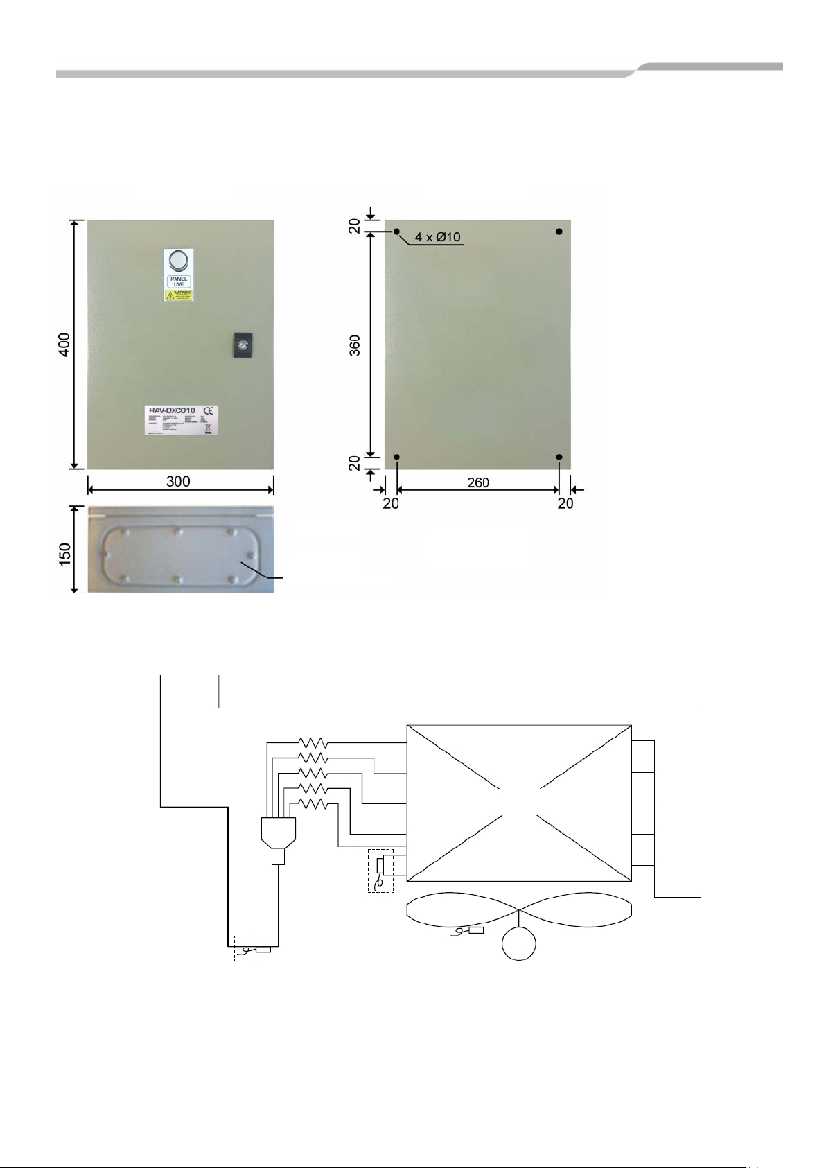
Gland Plate
Units: mm
Dimensions Mounting Holes
Liquid Gas
Capillary tube
TCJ
TC
Fan Motor
Sensor
Fan
DX Coil
LC DX INTERFACE
The DX controller must not be installed outside. To avoid damage, when making holes for cables glands,
please first remove the Gland Plate from the LC DX Interface. To maintain w aterproof integrity IP65 glands
must be used through the gland plate.
Note: In areas where
there is a risk of dew
condensation
insulation (locally
sourced) should be
fitted to the DX
controller enclosure
Weight: 10kg
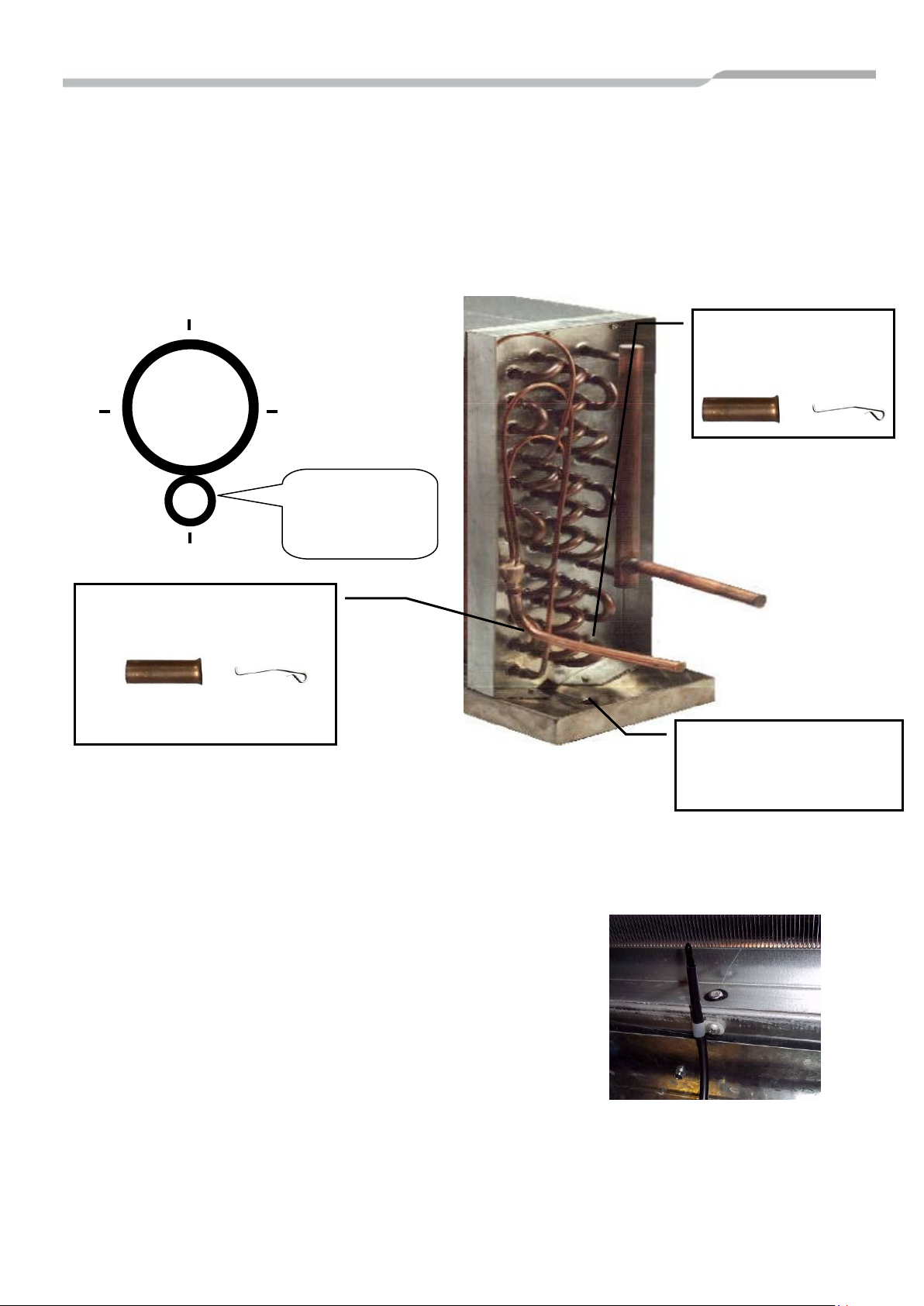
PIPING SCHEMATIC
Sensor Holder
(Brazing)
Lowest Circuit
rd
(2/3
’s through Pass)
Sensor Holder
(Brazing)
Notes:
1) To ensure reliable operation, all Sensor Holders must be fitted by brazing.
2) The TC Sensor Holder must be brazed to return bend 2/3
3) For brazing, be sure to use nitrogen gas to avoid oxidation of pipe inner surface.
(TA)
rd
’s through pass on the DX Coil’s lowest circuit.
6
LC DX Interface
Installation Manual
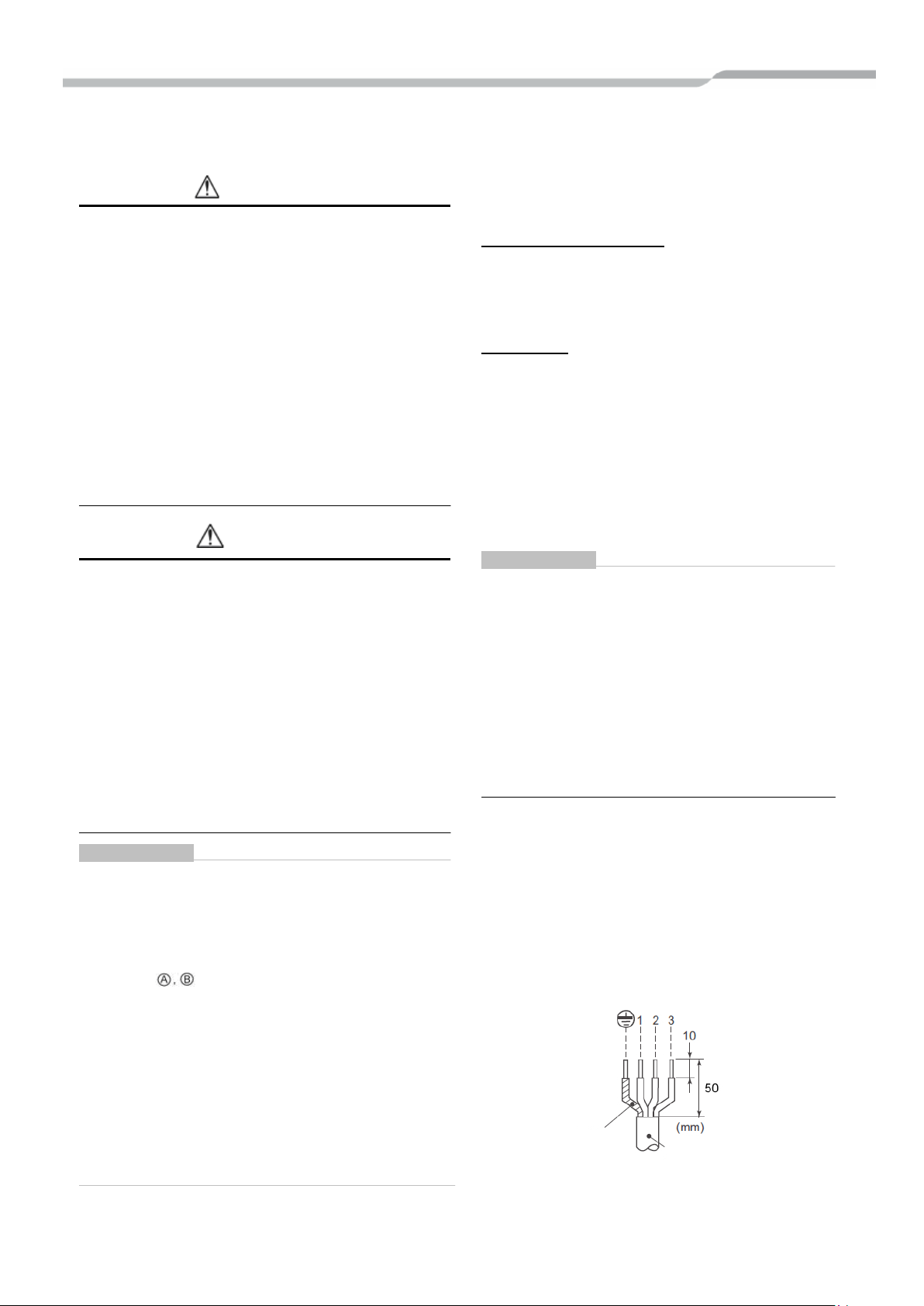
TC Sensor
Avoid positioning Sens or
TCJ Sensor
6 3 9
12
Sensor Holders
position.
DX COIL PREPARATION
Sensor Holders MUST be brazed on to the DX Coil pipe work to ensure reliable temperature sensing. There
are two coil sensors, these are inserted into the Sensor Holders, and secured with the sensor-fix-plate. The
sensor holders should be brazed at the 6 o’clock position.
It is essential that the sensors are correctly located to ensure efficient system performance.
For brazing, be sure to use nitrogen gas to avoid oxidation of pipe inner surface.
(Sensor Holder).
1 x Braze.
This should be brazed to the Liquid
Pipe.
TA SENSOR
should be brazed
at the 6 o’clock
Secure this sensor using the supplied plastic clamp. It must
be located in the Return Air Flow (Prior to mixing with any
fresh air). Ensure that the Resin Sensor bulb is not covered
by the protective vinyl-tube.
(Sensor Holder).
1 x Braze.
2/3rds across lowest circuit
holders in the Drain Pan where
they could be immersed in
water.
7
LC DX Interface
Installation Manual
WARNING
• Do not turn on the power of the indoor unit until
Earth Line
Connecting wire
4 ELECTRICAL WORK
1. Using the specified wires, ensure to connect
the wires, and fix wires securely so that the
external tension to the wires do n o t affect the
connecting part of the terminals.
Incomplete connection or fixation may cause a fire,
etc.
2. Be sure to connect earth wire (grounding work).
Incomplete grounding cause an electric shock.
Do not connect ground wires to gas pipes, water
pipes, lightning rods or ground wires for telephone
wires.
3. Appliance shall be installed in accordance with
national wiring regulations.
Capacity shortage of power circuit or incomplete
installation may cause an electric shock or a fire.
CAUTION
• This indoor unit has no power cord.
• If incorrect / incomplete wiring is carried out, it will
cause an electrical fire or smoke.
• Install an earth leakage breaker.
If an earth leakage breaker is not installed, an
electric shock may be caused.
• Be sure to use the cord clamps attached to the
product.
• Do not damage or scratch the conductive core and
inner insulator of power and inter-connect ing wires
when peeling them.
• Use the power cord and inter-connecting wire of
specified thickness, type and protective devices
required
REQUIREMENT
• For power supply wiring, strictly conform to the
Local Regulation for each country.
• For wiring of power supply of the outdoor units,
follow the Installation manual of each outdoor unit.
• Never connect 220-240V power to the terminal
blocks (
system will fail).
• Perform the electric wiring so that it does not come
in to contact with the high-temperature part of the
pipe.
The coating may melt in an accident
• After connecting wires to the terminal blocks, be
sure to leave sufficient wire before fixing with the
cord clamp.
• Run the refrigerant piping and control wiring line in
the same line.
, etc) for control wiring (otherwise the
vacuuming of the refrigerant pipes is completed.
Remote controller wiring
2-core non polarity wire is used for the remote
controller wiring.
How to wire
1. Connect the wires from the terminal block on the
outdoor unit to the same numbered terminal on
the LC DX Interface terminal block. Use wires to
H07 RH-F or 60245 IEC 66 (1.5mm
2. In the case of unsheathed redundant cords
(conductors) be sure to insulat e w ith e lectrical
insulation tape.
Fix them so that they do not touch any electrical
or metal parts.
REQUIREMENT
• Be sure to connect the wires matching the
terminal numbers. Incorrect connection causes a
trouble.
• Be sure to pass the wires through the bushing of
the wiring connection port of the LC DX interface.
• Keep a margin (approx. 100mm) on a wire to
hang down the electrical parts box at servicing,
etc.
• The low-voltage circuit is provided for the remote
controller (Do not connect the high-voltage
circuit).
• Wiring
1. Open the LC DX interface using the key
provided.
2. Strip wire ends (10mm).
3. Connect the wires from the terminal block on the
outdoor unit to the same numbered terminal on
the LC DX Interface terminal block.
4. Connect the ground wires to the corresponding
terminals.
5. Close the LC DX Interface with key provid ed.
2
or more).
8
LC DX Interface
Installation Manual
2
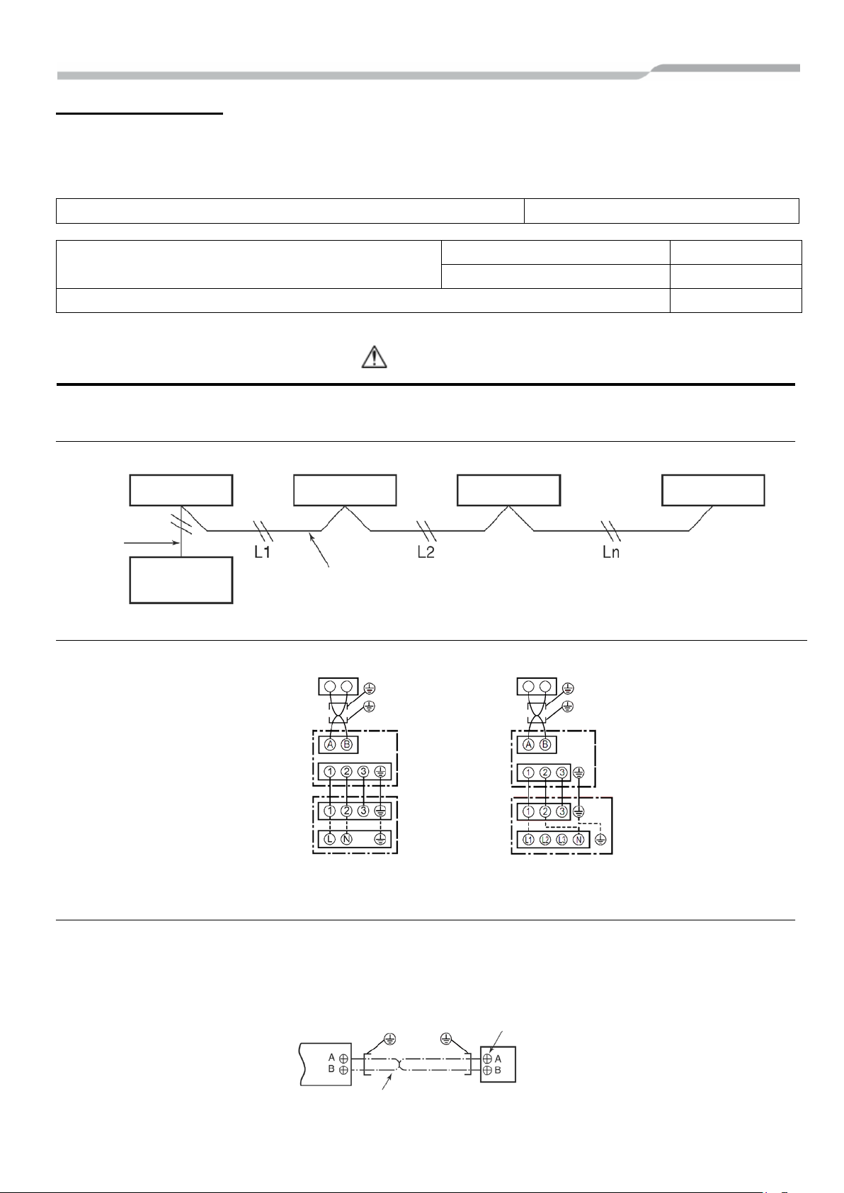
Remote controller inter-unit wiring
(Max. 8 units)
Remote
Controller
Indoor Unit
Indoor Unit
Indoor Unit
Indoor Unit
Remote
Terminal block
Remote
Terminal block for
wiring of indoor unit
Remote controller wire
Remote Controller
Remote Controller
Power Supply Power Supply
Remote controller wiring
• 2-core with non-polarity wire is used for wiring of the remote controller wiring and group remote controllers wiring
(0.75mm
2
to 2.5mm2)
• Strip off approx. 9mm the wire to be connected.
Remote controller wiring. Remote controller inter-unit wirin g Wire size: 0.75mm
to 2.5mm2
Total wire length of remote controller wiring and remote
controller inter-unit wiri ng = L + L1 + L2 + ……..Ln
In case of wired type only Up to 500m
In case of wireless type included Up to 400m
Total wire length of remote controller inter-unit wiring = L + L1 + L2 + ……..Ln Up to 200m
CAUTION
The remote controller wire (communication line) and AC220-240V wires cannot be parallel to contact each other and
cannot be stored in the same conduits. If doing so, a trouble may be caused on the control system due to noise, etc.
Controller
wiring
Wiring between indoor and outdoor units
▼ Single phase ▼ Three phase
Remote controller wiring
• As the remote controller wire has non-polarity, there is no problem if connections to indoor unit terminal blocks A
and B are reversed.
▼ Wiring diagram
Remote controller
Wiring
Indoor side
Indoor / Outdoor
Connecting wires
Outdoor side
remote controller
Remote controller
Wiring
Indoor side
Indoor / Outdoor
Connecting wires
Outdoor side
(Field supply)
Controller unit
 Loading...