

Toshiba RAV-CT100-M, RAV-CT150-M, RAV-CT200-M, RAV-CT100-L, RAV-CT150-L Installation And Owner's Manual
...
TOSHIBA Carrier (UK) Ltd.
For commercial use
RAV-CT100/150/200/250BH-M/L
DX Air Curtain Built-in (Medium / Large)
RAV-CT100/150/200/250CH-M/L
DX Air Curtain Free-Hanging (Medium / Large)
RAV-CT100/150/200/250UH-M/L
DX Air Curtain Cassette (Medium / Large)
DX Air Curtain
Installation and Owner's manual
Model name:
ENGLISH
1
DX Air Curtain
Contents
Please read this Installation Manual carefully before installing the DX Air Curtain.
ADOPTION OF R410A REFRIGERANT
This Air Conditioner is a type which adopts a HFC refrigerant (R410A) instead of the conventional
refrigerant R22 in order to prevent destruction of the ozone layer.
This appliance is for commercial use only and should not be accessible to the general public.
Children should be supervised to ensure that they do not play with the appliance.
Contents
1
INSTALLER: APPLICATION _ _ _ _ _ _ _ _ _ _ _ _ _ _ _ _ _ _ _ _ _ _ _ _ _ _ _ _ _ _ _
2
2
INSTALLER: PRECAUTIONS FOR SAFETY _ _ _ _ _ _ _ _ _ _ _ _ _ _ _ _ _ _ _ _ _ _ _
3
3
INSTALLER: INSTALLATION _ _ _ _ _ _ _ _ _ _ _ _ _ _ _ _ _ _ _ _ _ _ _ _ _ _ _ _ _ _ _
3
4
INSTALLER: ELECTRICAL WORK _ _ _ _ _ _ _ _ _ _ _ _ _ _ _ _ _ _ _ _ _ _ _ _ _ _ _ _
6
5
INSTALLER: APPLICABLE CONTROLS _ _ _ _ _ _ _ _ _ _ _ _ _ _ _ _ _ _ _ _ _ _ _ _ _
9
6
INSTALLER: TEST RUN _ _ _ _ _ _ _ _ _ _ _ _ _ _ _ _ _ _ _ _ _ _ _ _ _ _ _ _ _ _ _ _ _ _
15
7
INSTALLER: TROUBLE SHOOTING _ _ _ _ _ _ _ _ _ _ _ _ _ _ _ _ _ _ _ _ _ _ _ _ _ _ _
16
8
INSTALLER: MAINTENANCE GUIDELINES _ _ _ _ _ _ _ _ _ _ _ _ _ _ _ _ _ _ _ _ _ _ _
19
9
INSTALLER: OPTIONAL PARTS _ _ _ _ _ _ _ _ _ _ _ _ _ _ _ _ _ _ _ _ _ _ _ _ _ _ _ _ _
20
10
INSTALLER: TECHNICAL SPECIFICATIONS _ _ _ _ _ _ _ _ _ _ _ _ _ _ _ _ _ _ _ _ _ _
21
11
INSTALLER: TECHNICAL DRAWINGS _ _ _ _ _ _ _ _ _ _ _ _ _ _ _ _ _ _ _ _ _ _ _ _ _ _
22
12
INSTALLER: DECLARATION OF CONFORMITY_ _ _ _ _ _ _ _ _ _ _ _ _ _ _ _ _ _ _ _ _
25
13
INSTALLER: SERVICE PARTS _ _ _ _ _ _ _ _ _ _ _ _ _ _ _ _ _ _ _ _ _ _ _ _ _ _ _ _ _ _
26
14
OWNER: PRECAUTIONS FOR SAFETY _ _ _ _ _ _ _ _ _ _ _ _ _ _ _ _ _ _ _ _ _ _ _ _ _
27
15
OWNER: REMOTE CONTROLLER _ _ _ _ _ _ _ _ _ _ _ _ _ _ _ _ _ _ _ _ _ _ _ _ _ _ _ _
28
16
OWNER: CORRECT USAGE _ _ _ _ _ _ _ _ _ _ _ _ _ _ _ _ _ _ _ _ _ _ _ _ _ _ _ _ _ _ _
31
17
OWNER: TIMER OPERATION _ _ _ _ _ _ _ _ _ _ _ _ _ _ _ _ _ _ _ _ _ _ _ _ _ _ _ _ _ _
33
18
OWNER: MAINTENANCE _ _ _ _ _ _ _ _ _ _ _ _ _ _ _ _ _ _ _ _ _ _ _ _ _ _ _ _ _ _ _ _ _
34
19
OWNER: AIR CONDITIONER OPERATIONS AND PERFORMANCE _ _ _ _ _ _ _ _ _ _
36
• This Manual describes the installation method of the DX Air Curtain.
• You must also refer to the Installation Manual attached to the Toshiba outdoor unit.
This appliance is not intended for use by person (including children) with reduced physical, sensory or
mental capabilities, or lack of experience and knowledge, unless they have been given supervision or
instruction concerning use of the appliance by a person responsible for their safety.
This symbol mark is for EU countries only. This symbol mark is according to the directive 2002/96/EC Article
10 Information for users and Annex IV.
This product is designed and manufactured with high quality materials and components which can be
recycled and reused.
This symbol means that electrical and electronic equipment, at the end-of-life, should be disposed of
separately from your household waste.
Please dispose of this equipment at your local community waste collection / recycling centre.
In the European Union there are separate collection systems for used electrical and electronic product.

2
DX Air Curtain
Installer
1 APPLICATION
Every air curtain is manufactured conforming with European directives and the latest standards. Air curtains prevent air
currents and draughts and produce a comfortable environment in the door entrance area
The air curtains are manufactured to the latest technical standards and regulations. The quality controls include
material and function controls and ensure a quality product with a long life span.
The air curtains are built to CE guide lines.
The fan-motors used in the Air Curtain comply with ErP 2013 (Commission Regulation (EU) No 327/2011).
Correct installation is of paramount importance. This includes that unit and control are also used in the correct
environment. The air curtains and controls are manufactured for indoor use only.
Do not install in humid, aggressive or explosive areas. During the installation the unit has to be kept clean and dry.
Applications:
DX Air curtains are only applicable:-
For indoor areas (shops, warehouses, exhibition halls, or banks, etc.)
Installed in false ceilings or free hanging
DX Air curtains must not be installed:-
In humid areas like swimming pools
Areas with danger of explosion
Areas with aggressive air
Areas with extreme high dust exposure
Vertically (Only horizontally hung installations are permitted)
Twin / Triple Restriction:
To ensure reliable operation DX Air Curtains must be connected to a single outdoor unit (no twin or triple installations).
Model Range:
Built-in unit (BH)
Suitable for installation in the ceiling space above the door, only the inlet
grille and discharge outlet will be visible.
Door widths: 1.0m, 1.5m, 2.0m and 2.5m
2 versions offered: Medium (Door height range: 2.5m to 3.0m)
Large (Door height range: 2.7m to 3.2m)
Free-Hanging unit (CH)
Suitable for installation above the door, where whole unit will be visible.
Door widths: 1.0m, 1.5m, 2.0m and 2.5m
2 versions offered: Medium (Door height range: 2.5m to 3.0m)
Large (Door height range: 2.7m to 3.2m)
Cassette unit (UH)
Suitable for installation where the ceiling space is limited above the door,
the full panel will be visible.
Door widths: 1.0m, 1.5m, 2.0m and 2.5m
2 versions offered: Medium (Door height range: 2.5m to 3.0m)
Large (Door height range: 2.7m to 3.2m)
"Air On" Temperature Limits: Minimum 15°CDB / Maximum 28°CDB
In Heating mode (reverse cycle) when the outdoor unit is producing hot gas, the DX coil in the Air Curtain is effectively
the condenser. Air temperatures flowing across the coil below this level, can cause over condensing of the refrigerant.
This can result in liquid being returned to the compressor which will cause a mechanical failure of the outdoor unit. Low
air temperatures will also cause the unit to use it's defrost mode more often
3
DX Air Curtain
Installer
M (Medium)
2.5 – 3.0 m
L (Large)
2.7 – 3.2 m
Refrigerant (R410A) Air Conditioner Installation
To Disconnect the Appliance from Main Power Supply
Ceiling mounting kit
Electrical connections
Inlet grill
Access cover
Door
frame
External
wall
2 PRECAUTIONS FOR SAFETY
• Ensure that all Local, National and International regulations are satisfied.
• Read this "PRECAUTIONS FOR SAFETY" carefully before installation.
• The precautions described below include the important items regarding safety. Observe them without fail.
• After the installation work, perform a trial operation to check for any problem.
• Follow the installation manual to explain how to use and maintain the unit to the customer.
• Turn off the main power supply switch (or breaker) before the unit maintenance.
• Ask the customer to keep the installation manual.
• THIS AIR CONDITIONER ADOPTS THE HFC REFRIGERANT (R410A) WHICH DOES NOT DESTROY OZONE
LAYER.
The characteristics of R410A refrigerant are; easy to absorb water, oxidizing membrane or oil, and its pressure is
approx. 1.6 times higher than that of refrigerant R22. Accompanied with the new refrigerant, refrigerating oil has also
been changed. Therefore, during installation work, be sure that water, dust, former refrigerant, or refrigerating oil does
not enter the refrigerating cycle.
To prevent charging an incorrect refrigerant and refrigerating oil, the sizes of connecting sections of charging port of
the main unit and installation tools are changed from those of conventional refrigerant.
Accordingly the exclusive tools are required for the new refrigerant (R410A).
For connecting pipes, use new and clean piping designed for R410A, and please care so that water or dust does not
enter. Moreover, do not use the existing piping because there are problems with the pressure-resistance force and
impurity in it.
This appliance must be connected to the main power supply by means of a switch with a constant separation of at least
3mm.
3 INSTALLATION
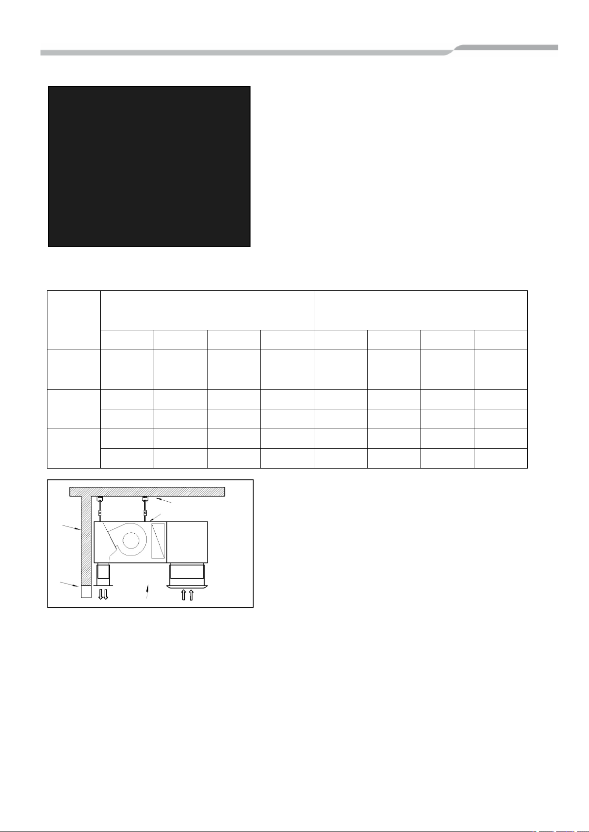
POSITIONING OF THE AIR CURTAIN
The unit should be installed as close as possible to the wall and
as flush as possible to the top of the door.
The outlet flow should always be free and not interrupted or
obstructed.
Don‘t exceed the recommended installation height recommended
per type. Type plate can be found on the inside of the access
panel.
Installation height
Type Door Height Range
• DO NOT STAND UNDERNEATH THE UNIT WHILE LIFTED OR DURING INSTALLATION
• DO ONLY USE APPROPRIATE TOOLS FOR LIFTING AND INSTALLING
• FOLLOW ALL LOCAL RULES AND REGULATIONS
4
DX Air Curtain
Installer
Pressure
Fa
DX Coil
Inlet plenum
Access
Free-Hanging (CH)
Built-in (BH)
Cassette (UH)
Ceiling mounting kit
Electrical connections
Inlet grill
Access cover
Door
frame
External
wall
Ceiling mounting
kit
Electrical
connections
Inlet grill
Access cover
Door
frame
External
wall
Ceiling mounting kit
Electrical connections
Inlet grill
Access cover
Door
frame
External
wall
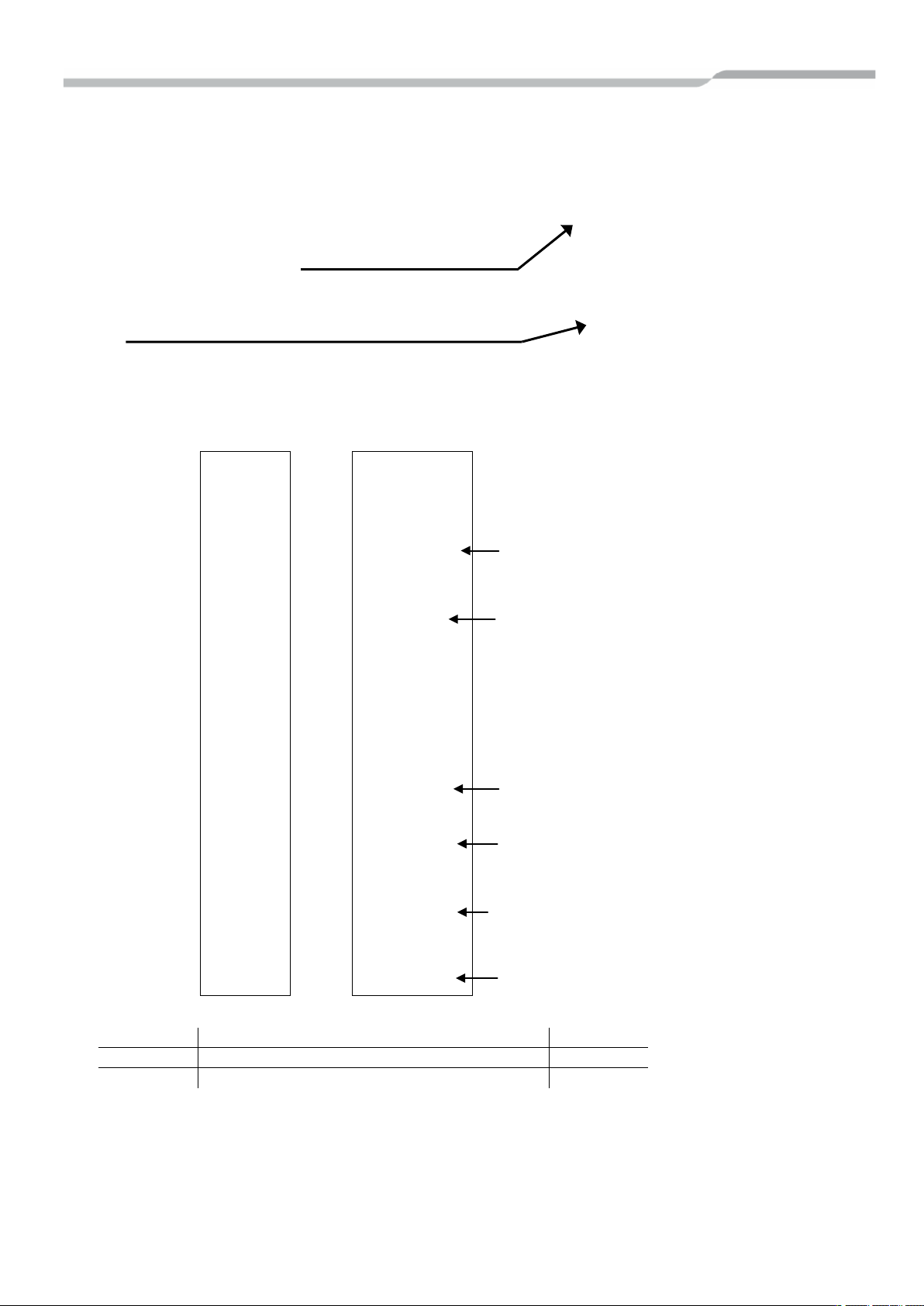
The access panel and E-Box cover has to be accessible at all times!
In all situations the accessibility of the unit over the whole length of
the unit has to be ensured.
Please refer to the technical drawings for dimensions.
For installation within a c eiling void it has to be ensured that the
access panel between in and out let grille is accessible over the
whole length of the unit.
The sliding type (BH) sections have to be fixed at the desired height
(use methods suitable to avoid vibrations).
CEILING MOUNTING
Please use the fixing points. The number of fixing points depends on model and length of the air curtain.
Model
Free-Hanging (CH)
(RAV-)
CT100 CT150 CT200 CT250 CT100 CT150 CT200 CT250
Fixing
points
1.0m 1.5m 2.0m 2.5m 1.0m 1.5m 2.0m 2.5m
M M M
4
L L L - L L L -
- - -
6
- - - L - - - L
Built-in (BH)
-
M
Cassette (UH)
M M M
- - -
-
M
5
DX Air Curtain
Installer
CODE
DESCRIPTION
DETAILS
3871
Ceiling mounting kit (1,0m / 1,5m / 2,0m)
M8 x 4
4034
Ceiling mounting kit (2,5m)
M8 x 6
Lock nut M 8
Hanging rod M 8
length 1 m
lock nut M 8
Spanner nut M 8
Set screw M 8 with left-hand and right-hand
Lock nut M 8
FLARE NUT CONNECTION
The Air Curtain is fitted with R410A Flare Nuts and is charged with
Nitrogen Gas (1 barg) when shipped.
Please refer to the installation Manual attached to the Toshiba
Outdoor unit for flare nut instructions.
Gas Pipe External ∅15.9mm
Liquid Pipe External ∅9.5mm (Remove Schrader pipe)
OPTIONAL CEILING MOUNTING KIT
Ceiling mounting kit with vibration absorber and sound insulation bracket:-
Setting range 30
Wall plugs are not included in the delivery!
When choosing the wall plug, please refer to the weight of the unit and the certification of the material
When assembling the spanner nut, please make sure that all hanging rods and set screws are properly fitted together.
All parts must be countered with a lock nut.

6
DX Air Curtain
Installer
• Do not turn on the power of the indoor unit until
4 ELECTRICAL WORK
WARNING
1. Using the specified wires, ensure to connect
the wires, and fix wires securely so that the
external tension to the wires do not affect the
connecting part of the terminals.
Incomplete connection or fixation may cause a fire,
etc.
2. Be sure to connect earth wire (grounding work).
Incomplete grounding cause an electric shock.
Do not connect ground wires to gas pipes, water
pipes, lightning rods or ground wires for telephone
wires.
3. Appliance shall be installed in accordance with
national wiring regulations.
Capacity shortage of power circuit or incomplete
installation may cause an electric shock or a fire.
CAUTION
• This indoor unit has no power cord.
• If incorrect / incomplete wiring is carried out, it will
cause an electrical fire or smoke.
• Install an earth leakage breaker.
If an earth leakage breaker is not installed, an
electric shock may be caused.
• Be sure to use the cord clamps attached to the
product.
• Do not damage or scratch the conductive core and
inner insulator of power and inter-connecting wires
when peeling them.
• Use the power cord and inter-connecting wire of
specified thickness, type and protective devices
required
REQUIREMENT
• For power supply wiring, strictly conform to the
Local Regulation for each country.
• For wiring of power supply of the outdoor units,
follow the Installation manual of each outdoor unit.
• Never connect 220-240V power to the terminal
blocks ( , etc) for control wiring (otherwise the
system will fail).
• Perform the electric wiring so that it does not come
in to contact with the high-temperature part of the
pipe.
The coating may melt in an accident
• After connecting wires to the terminal blocks, be
sure to leave sufficient wire before fixing with the
cord clamp.
• Run the refrigerant piping and control wiring line in
the same line.
vacuuming of the refrigerant pipes is completed.
Remote controller wiring
2-core non polarity wire is used for the remote
controller wiring.
How to wire
1. Connect the wires from the terminal block on the
outdoor unit to the same numbered terminal on
the DX Air Curtain terminal block. Use wires to
H07 RH-F or 60245 IEC 66 (1.5mm
2. In the case of unsheathed redundant cords
(conductors) be sure to insulate with electrical
insulation tape.
Fix them so that they do not touch any electrical
or metal parts.
REQUIREMENT
• Be sure to connect the wires matching the
terminal numbers. Incorrect connection causes a
trouble.
• Be sure to pass the wires through the bushing of
the wiring connection port of the DX e Msm- dop m"ialM1 eMthe MMMMMM
2
or more).

8
DX Air Curtain
Installer
WIRING DIAGRAM

9
DX Air Curtain
Installer
Approx. 5 minutes
Power
Remote
flashes
goes out
Approx. 1 minutes
Power
Remote
flashes
goes out
5 APPLICABLE CONTROLS
REQUIREMENT
• When you use this air conditioner for the first time,
it takes approx. 5 minutes until the remote
controller becomes available after power-on. This
is normal.
<When the power is turned on for the first time
after installation>
It takes approx. 5 minutes until the remote
controller becomes available.
Changing of settings for
applicable controls
Basic procedure for changing settings
Change the settings while the air conditioner is not
working.
(Be sure to stop the air conditioner before making
settings).
on
controller
is available
<When the power is turned on for the second
(or later) time>
It takes approx. 1 minute until the remote
controller becomes available.
on
• Normal settings were made when the unit was
shipped from factory.
Change the indoor unit as required.
• Use the wired remote controller to change the
settings.
• The settings cannot be changed using the wireless
remote controller, sub remote controller, or remote
controller-less system (for central remote controller
only).
Therefore, install the wired remote controller to
change the settings.
controller
is available
Procedure 1
Push + + buttons simultaneously for at
least 4 seconds.
After a while, the display flashes as shown in the
figure.
Confirm that the CODE No. is [10].
• If the CODE No. is not [10] push button to
erase the display content and repeat the
procedure from the beginning.
(No operation of the remote controller is accepted
for a while after button is pushed).
(While air conditioners are operated under the
group control, "ALL" is displayed first. When
is pushed, the indoor unit number
displayed following "ALL" is the header unit).
(* Display content varies with the
indoor unit model).
10
DX Air Curtain
Installer
Procedure 2
Procedure 5
DIRTY FILTER ALARM
(Disabled)
CENTRAL CONTROL ADDRESS
(Unset)
AUTO MODE
(Disabled)
POWER ADDRESS
(Unset)
DEVICE ADDRESS
(Unset)
GROUP ADDRESS
(Unset)
AVAILABLE MODE
(Heating & Fan Only)
DX Air Curtain Configuration
Each time you push button, indoor unit
numbers in the control group change cyclically.
Select the indoor unit you want to change settings for.
The fan of the selected unit runs and the louvers start
swinging. You can confirm the indoor unit for which
you want to change settings.
Procedure 3
Using "TEMP", buttons, specify CODE
NO. [ ].
Procedure 4
Using timer "TIME" buttons, select SET
DATA [ ].
Push button. When the display changes from
flashing to lit, the setup is completed.
• To change settings of another indoor unit, repeat
from procedure 2.
• To change other settings of the selected indoor unit,
repeat from procedure 3.
Use button to clear the settings.
To make settings after button was pushed,
repeat from procedure 2.
Procedure 6
When settings have been completed, push button
to determine the settings.
When button is pushed, flashes and then
the display content disappears and the air conditioner
enters the normal stop mode.
(While is flashing, no operation of the remote
controller is accepted).
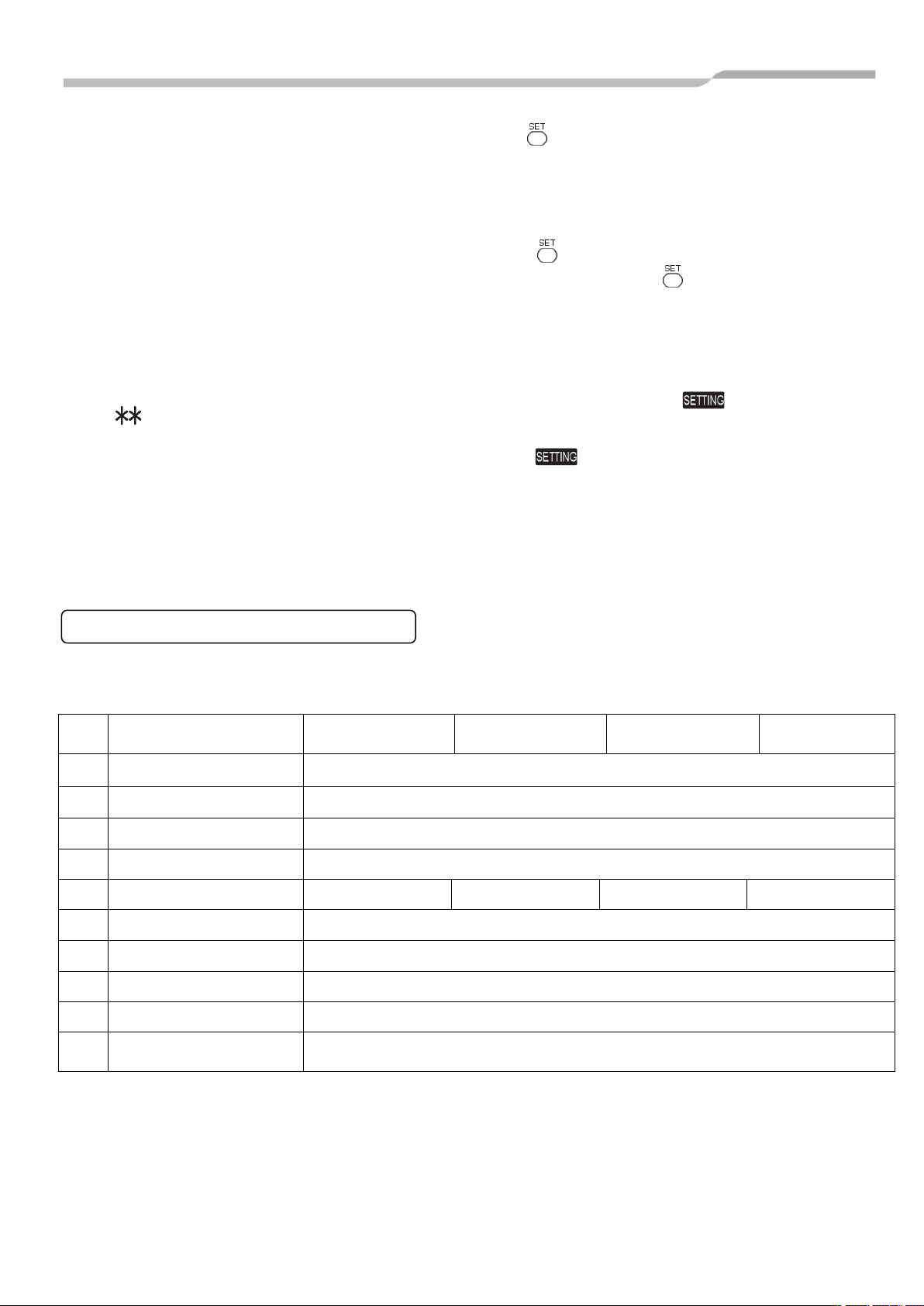
The circuit board of the DX AIR CURTAIN is configured at the factory. For reference these are the settings used. Any
changes must be set using the DN code menu.
Follow to the basic operation procedure (1 → 2 → 3 → 4 → 5 → 6).
DN
CODE
01
03
0d
10 DEVICE TYPE
11 CAPACITY CODE
12
13
14
2d
9b
* 0099 = address not assigned (system addresses are assigned during the automatic addressing by the system.
Central addresses can be assigned automatically with a central remote control or manually. Subsequent
modifications may lead to malfunction.)
DX AIR CURTAIN MODEL
(RAV-****-M/L)
FAN CONTROL
(Disabled)
CT100BH/CH/UH CT150BH/CH/UH CT200BH/CH/UH CT250BH/CH/UH
0000
0099*
0001
0004
0012 0015 0017 0018
0099*
0099*
0099*
0009
0001 (Fan motor operates during defrost cycle)
(To stop fan motor operation during defrost cycle change to 0000)
11
DX Air Curtain
Installer
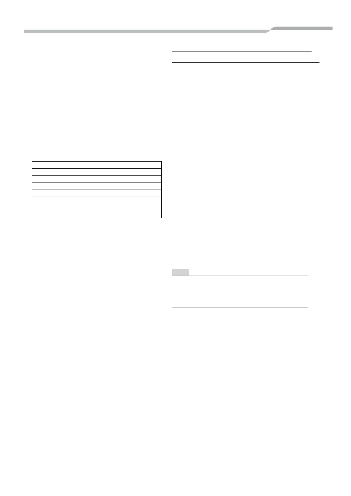
To secure better effect of
Setup Data
Detection temp shift value
0000
No shift
0001
+1°C
0002
+2°C (at shipment from factory)
0003
+3°C
0004
+4°C
0005
+5°C
0006
+6°C
Group Control
Outdoor unit Outdoor unit Outdoor unit Outdoor unit Outdoor unit
heating
When it is difficult to obtain satisfactory heating
due to installation place of the indoor unit or
structure of the room, the detection temperature
of heating can be raised. Also use the circulator,
etc. to circulate heat air near the ceiling.
Follow to the basic procedure
(1→2→3→4→5→6).
• For the CODE No. in Procedure 3, specify
[06].
• For the set data in Procedure 4, select the
setup data of shift value of detection
temperature to be set up from the table
below.
In case of group control for system of multiple units.
One remote controller can control maximum 8 indoor units
as a group.
▼ In case of group control in single system.
Indoor unit Indoor unit Indoor unit Indoor unit Indoor unit
(Max. 8 units)
Remote controller Finish of address setup by Power- ON
• For wiring procedure and wiring method of the individual
line (Identical refrigerant line) system, follow to
"Electrical work".
• Wiring between lines is performed in the following
procedure.
Connect the terminal block (A/B) of the indoor unit
connected with a remote controller to the terminal blocks
(A/B) of the indoor units of other indoor units by wiring
the inter-unit wire of the remote controller.
• When the power supply has been turned on, the
automatic address setup starts and which indicates that
address is being set up on the display part. during setup
of automatic address, the remote controller operation is
not accepted.
Required time up to the finish of automatic
addressing is approx. 5 minutes.
NOTE
In some cases, it is necessary to change the address
manually after setup of the automatic address according to
the system configuration of the group control.
12
DX Air Curtain
Installer
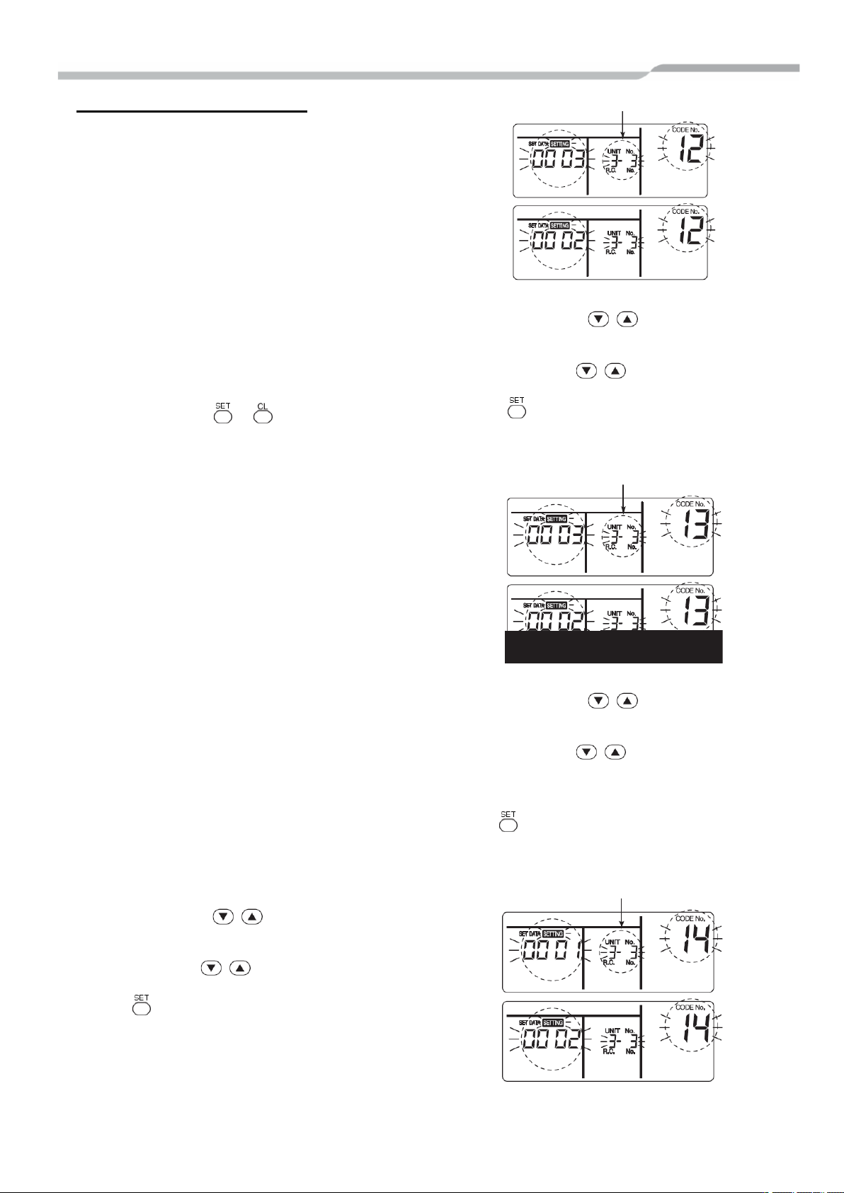
Group Control procedure example
Indoor unit No. before setup change is displayed.
(* Display changes according to
Manual address setup procedure
While the operation stops, change the setup.
(Be sure to stop operation of the unit).
Procedure 1
Push simultaneously + + buttons for 4
seconds or more. After a while, the display part
flashes as shown below. Check the displayed CODE
No. is [10].
• When the CODE No. is other than [10], push
button to erase the display and repeat procedure
from the first step.
(After pushing button, operation of the remote
controller is not accepted for approx. 1 minute).
(For group control, No. of the first displayed indoor
unit becomes the header unit).
the model No. of indoor unit.)
Procedure 2
Every pushing button, the indoor unit No. in
the group control is displayed in order. Select the
indoor unit of which setup is changed.
In this time, the position of the indoor unit of which
setup is changed can be confirmed because fan of
the selected indoor unit operate.
Procedure 3
1. Using temp. setup buttons, specify CODE
No. [12].
(CODE No. [12]: Line address).
2. Using timer time buttons, change the line
address from [3] to [2].
3. Push button.
In this time, the setup finishes when the display
changes from flashing to lighting.
Procedure 4
1. Using temp. setup buttons, specify
CODE No. [13].
(CODE No. [13]: Indoor address)
2. Using timer time buttons, change the
indoor address form [3] to [2].
3. Push button.
In this time, the setup finishes when the display
changes from flashing to lighting.
Indoor unit No. before setup change is displayed
Procedure 5
1. Using temp. setup buttons, specify
CODE No. [14].
(CODE No. [14]: Group address).
2. Using timer time buttons, change the
setup data from [0001] to [0002].
(Setup data [Header unit: 0001] [Follower unit:
0002])
3. Push button.
In this time, the setup finishes when display
changes from flashing to lighting.
Indoor unit No. before setup change is displayed
 Loading...