

Toshiba RAV-134TUH-1-PE, RAV-134AH-PE, RAV-164TUH-1-PE, RAV-164AH-PE, RAV-134TU-1-PE Service Manual
...
2 WAY CASSETTE TYPE
RAV-104TUH-1-PE
RAV-134TUH-1-PE/RAV-134AH-PE
RAV-164TUH-1-PE/RAV-164AH-PE
RAV-134TU-1-PE/RAV-134A-PE
RAV-164TU-1-PE/RAV-164A-PE
AIR-CONDITIONER
SPLIT TYPE, HEAT PUMP
COOLING ONLY
FILE NO. A90-0031
Printed in UK NOVEMBER 2000
TOSHIBA
SERVICE MANUAL
Heronhill - for all your Toshiba requirements
Tel: 01823 665660
www.heronhill.co.uk
Fax: 01823 665807
3
CONTENTS
1. SPECIFICATIONS 4
2. CONSTRUCTIONS VIEWS 7
3. WIRING DIAGRAMS 9
4. SPECIFICATIONS OF ELECTRICAL PARTS 13
5. REFRIGERANT PIPING DIAGRAMS 18
6. PERFORMANCE CHARACTERISTICS 23
7. EXPLODED VIEWS AND PARTS LISTS
26
The units referred to within this Manual conform with the protection requirements of Directives 89/336/EEC
Electromagnetic Compatibility and 73/23/EEC Low Voltage.
Operating conditions of units are as follows:
SUMMARY
OUTDOOR
TEMPERATURE
ROOM
TEMPERATURE
ROOM
HUMIDITY
-2 to 43˚C (COOL)
-10 to 21˚C (HEAT)
18 to 32˚C (COOL)
15 to 29˚C (HEAT)
LESS THAN 80% (COOL)
Diameter (mm)
Nominal Diameter (inch)
6.4 9.5 12.7 15.9 19 22
1/4 3/8 1/2 5/8 3/4 7/8
Cooling Capacity is based on the following temperature conditions:
Indoor air inlet temperature 27˚C DB, 19˚C WB.
Outdoor air inlet temperature 35˚C DB.
Heating Capacity is based on the following temperature conditions:
Indoor air inlet temperature 20˚C DB.
Outdoor air inlet temperature 7˚C DB, 6˚C WB.
For details on Control Circuits, refer to Service Manual A90-9925.
Metric/Imperial pipe conversion:
Note 1:
Note 2:
Note 3:
Note 4:
Heronhill - for all your Toshiba requirements
Tel: 01823 665660
www.heronhill.co.uk
Fax: 01823 665807
4
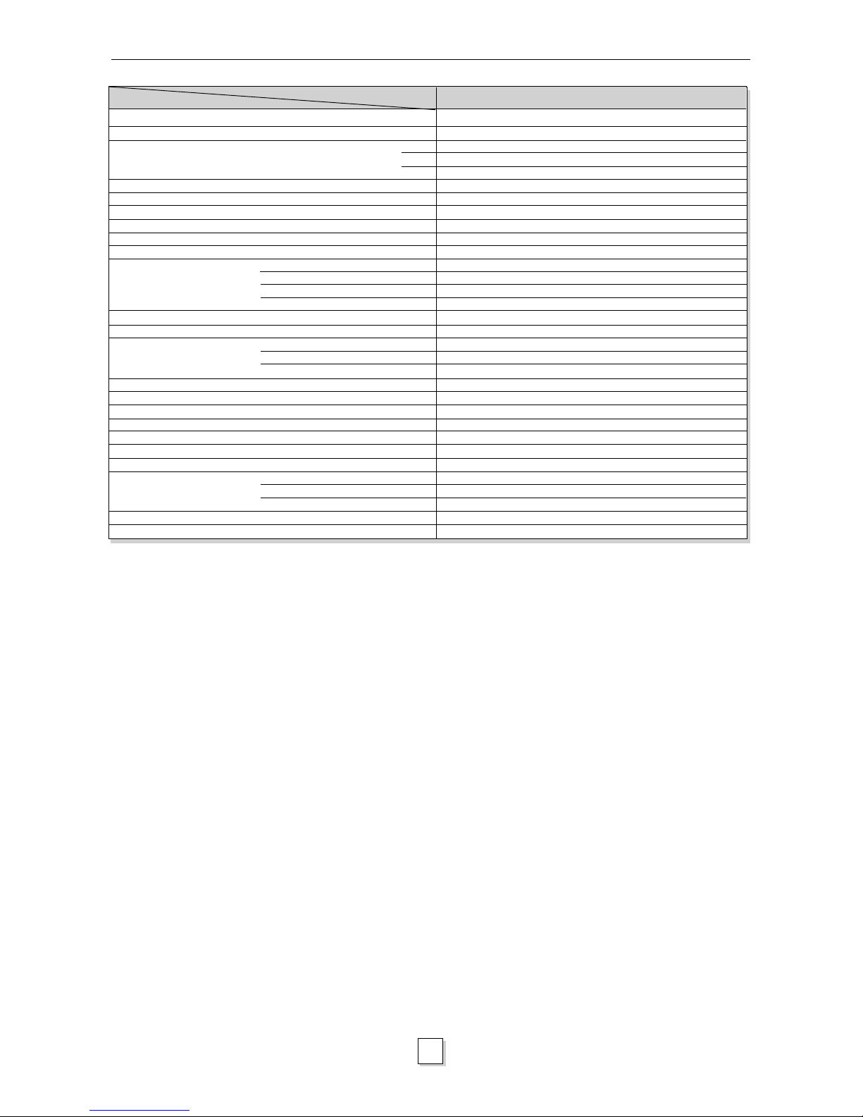
1. SPECIFICATIONS
Cooling capacity
Heating capacity
Power source
Power consumption
Power factor
Running current
Starting current
Operating noise (SPL)
Refrigerant
Interconnection
pipe
Condensate drain pipe diameter
Appearance colour
Dimensions
Net weight
Heat exchanger type
Indoor fan type
Air volume
Fan motor output
Ceiling Panel Model
Appearance Colour
Dimensions
Net Weight
Air Filter
kW
kW
Phase
V
Hz
kW
%
A
A
dB(A)
mm
mm
mm
mm
mm
mm
kg
m
3
/hr
W
mm
mm
mm
kg
2.5
2.8
1
220-240
50
0.07
93
0.33
0.6
40/36/34
R407C
ø12.7
Flare
ø6.4
Flare
ø25.5 (OD)
Grey (galvanized steel & thermal insulation)
190
910
480
23
Finned tube
Transverse flow fan
550
7 x 2
RBC-U134PG(W)-E
Silky white (Munsell 2.9Y8.9/0.8)
25
1,050
550
4.5
Washable
Indoor Unit (High/Med/Low)
Name of Refrigerant
Larger side size
Coupler style
Smaller side size
Coupler style
Height
Width
Depth
Height
Width
Depth
RAV-104TUH-1-PE
Specifications are subject to change without notice
Item Model
Heronhill - for all your Toshiba requirements
Tel: 01823 665660
www.heronhill.co.uk
Fax: 01823 665807
5
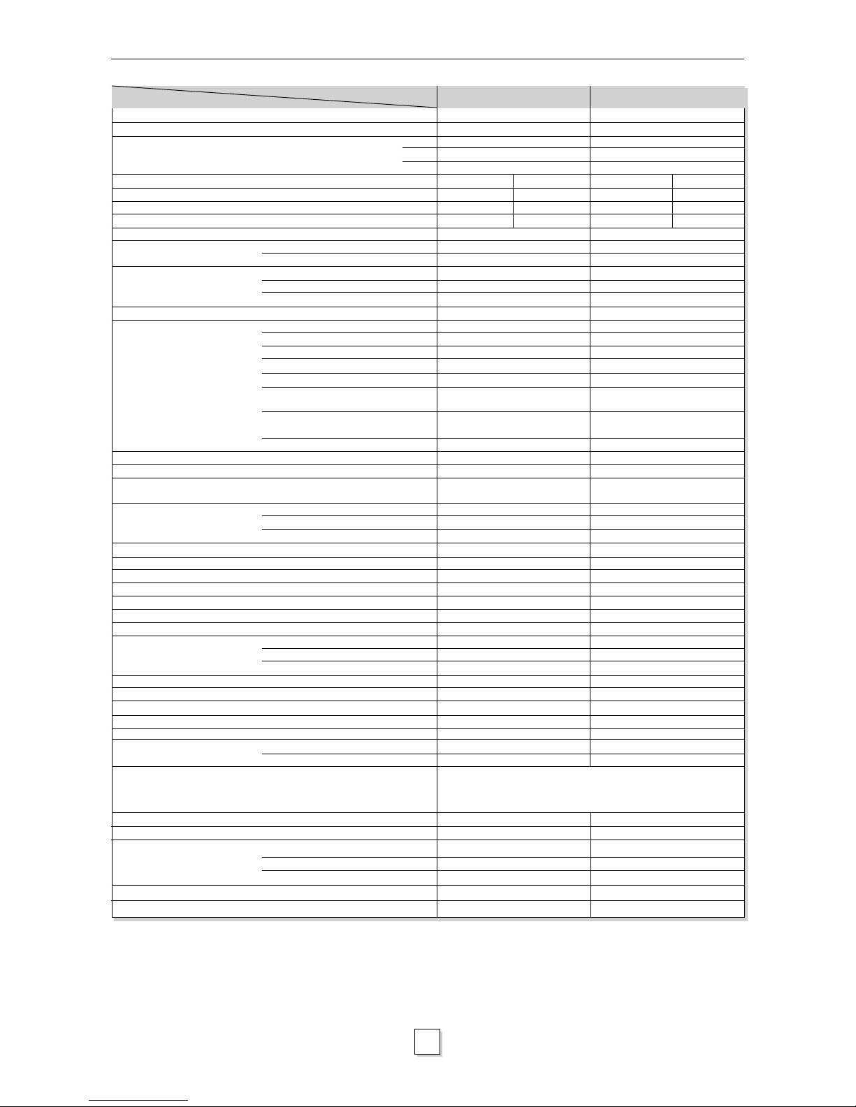
1. SPECIFICATIONS
Cooling capacity
Heating capacity
Power source
Power consumption
Power factor
Running current
Starting current
Operating noise
(SPL)
Refrigerant
Refrigerant control
Interconnection
pipe
Condensate drain pipe diameter
INDOOR UNIT Model
Appearance colour
Dimensions
Net weight
Heat exchanger type
Indoor fan type
Air volume
Fan motor output
OUTDOOR UNIT Model
Appearance colour
Dimensions
Net weight
Heat exchanger type
Outdoor fan type
Air flow volume
Fan motor output
Compressor
Protective device
CEILING PANELmodel
Appearance colour
Dimensions
Net weight
Air filter
kW
kW
Phase
V
Hz
kW
%
A
A
dB(A)
dB(A)
kg
g/m
mm
mm
m
m
m
m
mm
mm
mm
mm
kg
m
3
/h
W
mm
mm
mm
kg
m
3
/h
W
kW
mm
mm
mm
kg
3.6
4.2
1
220-240
50
COOLING HEATING
2.0 2.15
88 90
9.9 10.4
60
40/36/34
50
R407C
1.05
35
Capillary tube & Expansion valve
ø12.7
Flare
ø6.4
Flare
7.5
30
15
30
ø25.5 (OD)
RAV-134TUH-1-PE
Grey (galvanized steel &
thermal insulator)
190
910
480
23
Finned tube
Transverse flow fan
700
7 x 2
RAV-134AH-PE
Bronze white (Munsell 6Y7.5/1)
740
880
310
61
Finned tube
Propeller fan
2,700
39
PG330X3F-4LS
1.5
RBC-U134PG(W)-E
Silky white (Munsell 2.9Y8.9/0.8)
25
1,050
550
4.5
Washable
4.5
5.0
1
220-240
50
COOLING HEATING
2.2 2.2
90 89
10.6 10.7
60
41/37/35
50
R407C
1.2
35
Capillary tube & Expansion valve
ø12.7
Flare
ø6.4
Flare
7.5
30
15
30
ø25.5 (OD)
RAV-164TUH-1-PE
Grey (galvanized steel &
thermal insulator)
190
910
480
23
Finned tube
Transverse flow fan
750
7 x 2
RAV-164AH-PE
Bronze white (Munsell 6Y7.5/1)
740
880
310
61
Finned tube
Propeller fan
2,700
39
PG350X3F-4LS
1.5
RBC-U134PG(W)-E
Silky white (Munsell 2.9Y8.9/0.8)
25
1,050
550
4.5
Washable
Indoor Unit (High, Med, Low)
Outdoor Unit
Name of Refrigerant
Charge Volume
Add. Volume (20-30m)
Larger side size
Coupler style
Smaller side size
Coupler style
Standard length
Maximum actual pipe length
(of one way)
Maximum height difference
If Indoor Unit higher
If Outdoor Unit higher
Height
Width
Depth
Height
Width
Depth
Model
Output
Height
Width
Depth
Specifications are subject to change without notice
High pressure switch, fuse, crankcase heater, inner overload relay,
bi-metal thermostat
Item Model
RAV-164TUH-1-PERAV-134TUH-1-PE
Heronhill - for all your Toshiba requirements
Tel: 01823 665660
www.heronhill.co.uk
Fax: 01823 665807

6
1. SPECIFICATIONS
Cooling capacity
Power source
Power consumption
Power factor
Running current
Starting current
Operating noise
(SPL)
Refrigerant
Refrigerant control
Interconnection
pipe
Condensate drain pipe diameter
INDOOR UNIT Model
Appearance colour
Dimensions
Net weight
Heat exchanger type
Indoor fan type
Air volume
Fan motor output
OUTDOOR UNIT Model
Appearance colour
Dimensions
Net weight
Heat exchanger type
Outdoor fan type
Air flow volume
Fan motor output
Compressor
Protective device
CEILING PANELmodel
Appearance colour
Dimensions
Net weight
Air filter
kW
Phase
V
Hz
kW
%
A
A
dB(A)
dB(A)
kg
g/m
mm
mm
m
m
m
m
mm
mm
mm
mm
kg
m
3
/h
W
mm
mm
mm
kg
m
3
/h
W
kW
mm
mm
mm
kg
3.6
1
220-240
50
COOLING
2.0
88
9.9
60
40/36/34
50
R407C
1.05
35
Capillary tube
ø12.7
Flare
ø6.4
Flare
7.5
30
15
30
ø25.5 (OD)
RAV-134TU-1-PE
Grey (galvanized steel &
thermal insulator)
190
910
480
23
Finned tube
Transverse flow fan
700
7 x 2
RAV-134A-PE
Bronze white (Munsell 6Y7.5/1)
740
880
310
58
Finned tube
Propeller fan
2,700
39
PG330X3F-4LS
1.5
RBC-U134PG(W)-E
Silky white (Munsell 2.9Y8.9/0.8)
25
1,050
550
4.5
Washable
4.5
1
220-240
50
COOLING
2.2
90
10.6
60
41/37/35
50
R407C
1.2
35
Capillary tube
ø12.7
Flare
ø6.4
Flare
7.5
30
15
30
ø25.5 (OD)
RAV-164TU-1-PE
Grey (galvanized steel &
thermal insulator)
190
910
480
23
Finned tube
Transverse flow fan
750
7 x 2
RAV-164A-PE
Bronze white (Munsell 6Y7.5/1)
740
880
310
58
Finned tube
Propeller fan
2,700
39
PG350X3F-4LS
1.5
RBC-U134PG(W)-E
Silky white (Munsell 2.9Y8.9/0.8)
25
1,050
550
4.5
Washable
Indoor Unit (High, Med, Low)
Outdoor Unit
Name of Refrigerant
Charge Volume
Add. Volume (20-30m)
Larger side size
Coupler style
Smaller side size
Coupler style
Standard length
Maximum actual pipe length
(of one way)
Maximum height difference
If Indoor Unit higher
If Outdoor Unit higher
Height
Width
Depth
Height
Width
Depth
Model
Output
Height
Width
Depth
Specifications are subject to change without notice
fuse, crankcase heater
RAV-164TU-1-PERAV-134TU-1-PE
Item Model
Heronhill - for all your Toshiba requirements
Tel: 01823 665660
www.heronhill.co.uk
Fax: 01823 665807
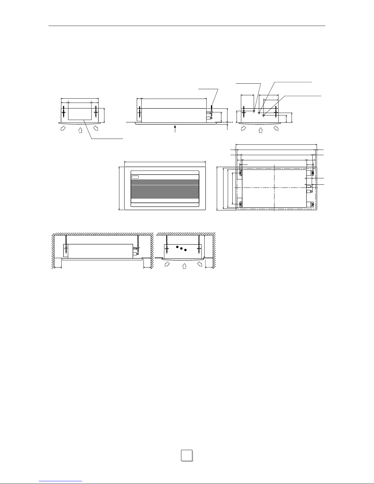
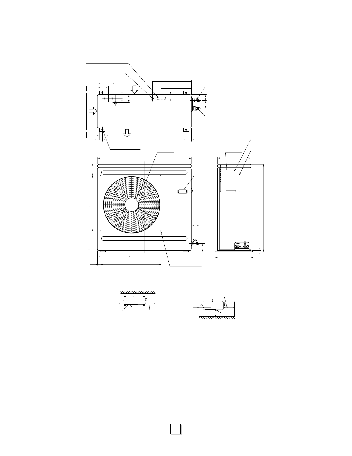
7
2. CONSTRUCTION VIEWS
480
330
76
76
190
70
840
Hanger bolt
(4-M10)
A
190
25
Drain pipe joint
(outer ø25.5)
Refrigerant piping joint
(Liquid ø6.4)
Refrigerant piping joint
(Gas ø12.7)
66
73
Panel outer dimension 1050
Ceiling opening 1010
Hang bolt pitch 930
840
20
40
70
40
20
40
110
90
Panel outer dimension 550
Ceiling opening 510
480
Hang bolt pitch 410
TOSHIBA
1050
550
600
Minimum
600
Minimum
600
Minimum
200
Space required for service and installation
View A
(Unit: mm)
96
131
156
Wiring connection
2.1
Indoor Unit
RAV-104TUH-1-PE
RAV-134TUH-1-PE
RAV-164TUH-1-PE
RAV-134TU-1-PE
RAV-164TU-1-PE
Heronhill - for all your Toshiba requirements
Tel: 01823 665660
www.heronhill.co.uk
Fax: 01823 665807
8
880
Air outlet
104
500
380
320
37
566
Blow out guide
mounting hole
(4-ø3 embosses)
90
88
Handle
(Both sides)
310
Electric
parts box
Earth screw (M6)
Terminal cover
740
364
18
12
165
117
40
340
12
45
50
790
70
360
280
30
5070
45
Hole for drain
(2xø19 hole)
Knock-out hole for drain
(2-20x60 slots)
Anchor bolt hole
(4-12x18slots)
Refrigerant pipe connection
(Liquid ø6.4)
Refrigerant pipe connection
(Gas ø12.7)
When installed with the
inlet facing the wall
(Space for wiring
and piping)
500
300
100
Outlet
Outlet
(Space for wiring
and piping)
100
100
500
Space required for service
When installed with the
outlet facing the wall
2. CONSTRUCTION VIEWS
2.2
Outdoor Unit
RAV-134AH-PE
RAV-164AH-PE
RAV-134A-PE
RAV-164A-PE
Heronhill - for all your Toshiba requirements
Tel: 01823 665660
www.heronhill.co.uk
Fax: 01823 665807
9
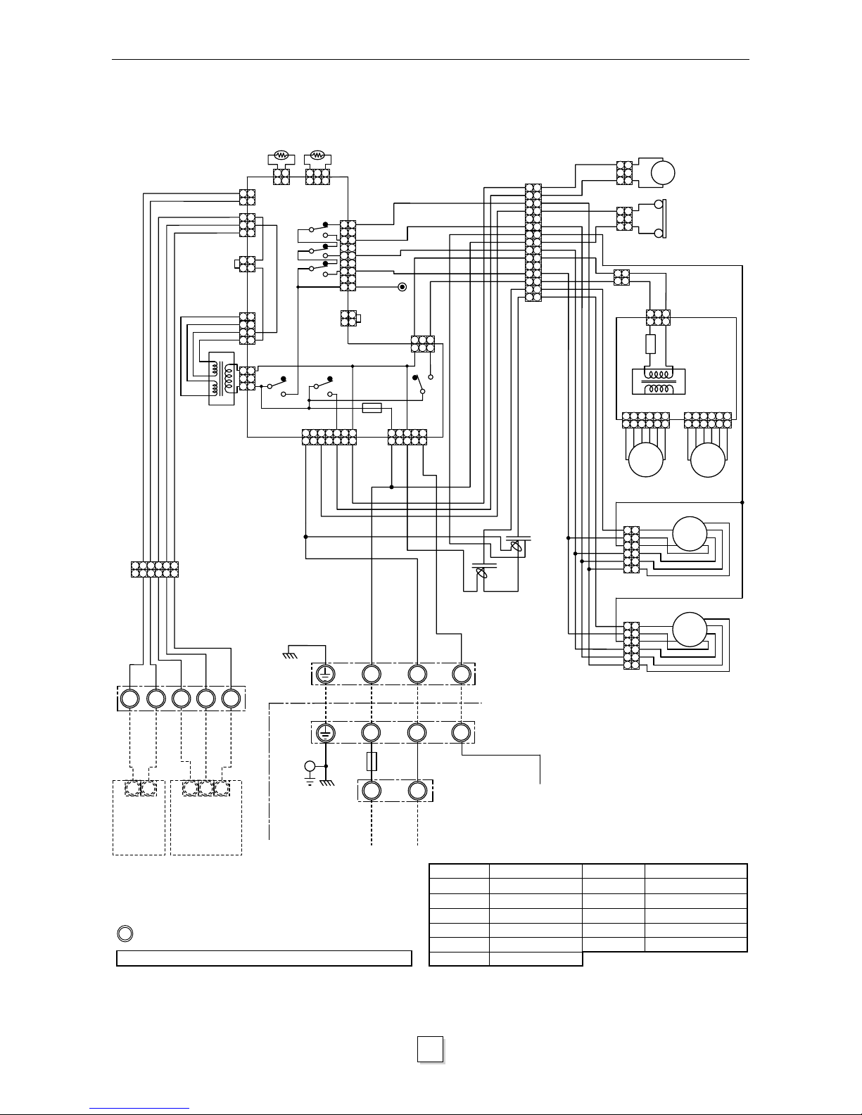
3. WIRING DIAGRAMS
1
3
1
3
1
313
2 2
4 4
TR
CN01
(TRANS)
CN12
3
1
3
1
2
2
CN15
(LAN)
5
3
1
13
5
7
13
5
7
5
31
TA
CN04
(TA)
CN05
(TC)
TC
REMOCON
RY02
RY03
RY04
UL
L
M
H
CN07
(FAN)
RY01
RY06
CN10
(PUMP)
F
(L1)
(N)
CN03
(SERIAL)
RY07
X
Y
A
B
C
X
Y
Central
Remote
Controller
(Optional)
A
B
C
Remote
Controller
(Optional)
Indoor unit
RED
PUR
RED
GRY
BLK
RY01
(output)
RED
YEL
BLU
ORG
BLK
Outdoor
unit
1
2
3
1
2
3
N
L
F
2
(1 Phase
model)
Power
Supply
220/240V
~50Hz
1
2
3
4
5
6
7
8
9
10
11
12
13
14
15
1
2
3
4
5
6
7
8
9
10
11
12
13
14
15
DM
CS
F
3
TR
Interface
PCB
SM
01
SM
02
WHI
RED
YEL
BLU
ORG
BLK
WHI
RED
1
2
3
4
5
6
1
2
3
4
5
6
1
2
3
4
5
6
1
2
3
4
5
6
FM
02
FM
01
RED
WHI
WHI
RED
YEL
ORG
BLU
BLK
RC02
RC01
WHI
WHI
1
1
2
2
GRY
GRY
CN09
(WHI)
(LOUVER)
BLK
BLK
Earth
Screw
GRN/YEL
CN02
YEL
ORG
BLU
RED
GRY
GRY
ORG
BLU
BLK
YEL
WHI
CN21
1
3
5
1 3
5
226
6
4
4
1
1
3
3
5
5
7
7
9
9
3.1
RAV-104TUH-1-PE
RAV-134TUH-1-PE
RAV-164TUH-1-PE
Shows terminal block and figures show terminal numbers.
Broken lines show wiring at site.
Do not operate the units with the magnetic contactor pushed in.
Symbol Name Symbol Name
FM01, 02 Fan Motor F Fuse (PCB)
RC01,02 Running Capacitor F3 Fuse(
Interface
)PCB
TR Transformer DM Drain Pump
TA Sensor SM01, 02 Stepper Motor
TC Sensor CS Float Switch
RY01~RY07
Relay
Heronhill - for all your Toshiba requirements
Tel: 01823 665660
www.heronhill.co.uk
Fax: 01823 665807
10
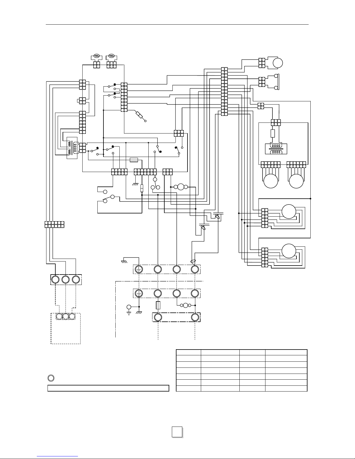
3. WIRING DIAGRAMS
RED
YEL
BLU
ORG
BLK
1
2
3
1
2
3
4
5
6
7
8
9
10
11
12
13
14
15
1
2
3
4
5
6
7
8
9
10
11
12
13
14
15
DM
CS
F
3
TR
SM
01
SM
02
WHI
RED
YEL
BLU
ORG
BLK
WHI
RED
1
2
3
4
5
6
1
2
3
4
5
6
1
2
3
4
5
6
1
2
3
4
5
6
FM
02
FM
01
RED
WHI
WHI
RED
YEL
ORG
BLU
BLK
RC01
RC02
WHI
WHI
BLK
BLK
GRN/YEL
1
3
1
3
1
313
22
4
4
TR
CN12
3
1
3
1
CN02
2
2
A
B
C
YEL
ORG
BLU
RED
ORG
BLU
BLK
YEL
WHI
5
7
5
7
6
6
CN01
(TRANS)
TA
CN04
(TA)
CN05
(TC)
TC
RY02
L
M
H
CN07
(FAN)
F
(L1)
(N)
CN03
1
3
5
7
1
3
5
7
99
75
3
1
75
3
1
31
31
CN11
(FLOAT)
RY03
RY01
RY14
RY07
RY11
1
35
1
35
A
B
C
1
2
3
N
L
F
2
4
6
3
4 6
3
552
2
1
1
43
1
3
5
43
6
42
8743
REMOCON
CN10
(PUMP)
RY01
(output)
CN09
(WHI)
(LOUVER)
Interface
PCB
Power
supply
220/240V
~50Hz
Outdoor
unit
Earth
screw
(1 Phase
model)
Indoor unit
Remote
Controller
(Optional)
3.2
RAV-134TU-1-PE
RAV-164TU-1-PE
Shows terminal block and figures show terminal numbers.
Broken lines show wiring at site.
Do not operate the units with the magnetic contactor pushed in.
Symbol Name Symbol Name
FM01, 02 Fan Motor F Fuse (PCB)
RC01, 02 Running Capacitor F3 Fuse (
Interface
)PCB
TR Transformer DM Drain Pump
TA Sensor SM01, 02 Stepper Motor
TC Sensor CS Float Switch
RY01~RY14
Relay 43 Relay
Heronhill - for all your Toshiba requirements
Tel: 01823 665660
www.heronhill.co.uk
Fax: 01823 665807
 Loading...