

Toshiba RAS-18N3KV2-E, RAS-B22N3KV2-E, RAS-18N3AV2-E, RAS-22N3AV2-E Service Manual
R410A
August, 2012
AIR-CONDITIONER
SPLIT TYPE
SERVICE MANUAL
FILE NO. SVM-12056
Outdoor Unit
<Heat Pump Type>
RAS-18N3AV2-E
RAS-22N3AV2-E
Indoor Unit
<High Wall, Heat Pump Type>
RAS-18N3KV2-E
RAS-
B22N3KV2-E
P
O
W
E
R
-
S
E
L
SWI
N
G
F
A
N
F
IX
QU
I
ET
H
i
P
O
W
E
R
ON
E
-T
OU
C
H
C
O
M
F
O
R
T
S
L
E
EP

CONTENTS
1. SAFETY PRECAUTIONS .......................................................................... 2
2. SPECIFICATIONS ...................................................................................... 5
3. REFRIGERANT R410A .............................................................................. 7
4. CONSTRUCTION VIEWS ........................................................................ 15
5. WIRING DIAGRAM .................................................................................. 17
6. SPECIFICATIONS OF ELECTRICAL PARTS ......................................... 19
7. REFRIGERANT CYCLE DIAGRAM ........................................................ 20
8. CONTROL BLOCK DIAGRAM ................................................................ 23
9. OPERATION DESCRIPTION ................................................................... 25
10. INSTALLATION PROCEDURE ................................................................ 49
11. HOW TO DIAGNOSE THE TROUBLE ....................................................... 64
12. HOW TO REPLACE THE MAIN PARTS ................................................... 86
13. EXPLODED VIEWS AND PARTS LIST ................................................... 102
FILE NO. SVM-12056
– 1 –

For general public use
Power supply cord of parts of appliance for outdoor use shall be at least polychloroprene sheathed flexible cord
(design H07RN-F) or cord designation 60245 IEC66 (1.5 mm2 or more). (Shall be installed in accordance with national
wiring regulations.)
CAUTION
New refrigerant air conditioner installation
• THIS AIR CONDITIONER ADOPTS THE NEW HFC REFRIGERANT (R410A), WHICH DOES NOT DESTROY
OZONE LAYER.
R410A refrigerant is apt to be affected by impurities such as water, oxidizing membranes, and oils because the
pressure of R410A refrigerant is approx. 1.6 times of refrigerant R22. As well as the adoption of this new refrigerant,
refrigerating machine oil has also been changed. Therefore, during installation work, be sure that water, dust,
former refrigerant, or refrigerating machine oil does not enter the refrigeration cycle of a new-refrigerant air
conditioner. To avoid mixing refrigerant and refrigerating machine oil, the sizes of charging port connecting port
connecting sections on the main unit are different from those for the conventional refrigerant, and different size tools
are also required. For connecting pipes, use new and clean piping materials with highpressure withstand
capabilities, designed for R410A only, and ensure that water or dust does not enter. Moreover, do not use any
existing piping as its pressure withstand may be insufficient and may contain impurities.
DANGER
• FOR USE BY QUALIFIED PERSONS ONLY.
• MEANS FOR DISCONNECTION FROM THE SUPPLY HAVING A CONTACT SEPERATION OF AT LEAST 3 mm
IN ALL POLES MUST BE INCORPORATED IN THE FIXED WIRING.
• TURN OFF MAIN POWER SUPPLY BEFORE ATTEMPTING ANY ELECTRICAL WORK, MAKE SURE ALL POWER
SWITCHES ARE OFF FAILURE TO DO SO MAY CAUSE ELECTRIC SHOCK.
• CONNECT THE CONNECTING CABLE CORRECTLY. IF THE CONNECTING CABLE IS CONNECTED WRONGLY,
ELECTRIC PARTS MAY BE DAMAGED.
• CHECK THE EARTH WIRE THAT IT IS NOT BROKEN OR DISCONNECTED BEFORE INSTALLATION.
• DO NOT INSTALL NEAR CONCENTRATIONS OF COMBUSTIBLE GAS OR GAS VAPORS.
FAILURE TO FOLLOW THIS INSTRUCTION CAN RESULT IN FIRE OR EXPLOSION.
• TO PREVENT OVERHEATING THE INDOOR UNIT AND CAUSING A FIRE HAZARD, PLACE THE UNIT WELL
AWAY (MORE THAN 2 M) FROM HEAT SOURCES SUCH AS RADIATORS, HEATERS, FURNACE, STOVES, ETC.
• WHEN MOVING THE AIR CONDITIONER FOR INSTALLING IT IN ANOTHER PLACE AGAIN, BE VERY
CAREFUL NOT TO GET THE SPECIFIED REFRIGERANT (R410A) WITH ANY OTHER GASEOUS BODY INTO
THE REFRIGERATION CYCLE. IF AIR OR ANY OTHER GAS IS MIXED IN THE REFRIGERANT, THE GAS
PRESSURE IN THE REFRIGERATION CYCLE BECOMES ABNORMALLY HIGH AND IT RESULTINGLY CAUSES
BURST OF THE PIPE AND INJURIES ON PERSONS.
• IN THE EVENT THAT THE REFRIGERANT GAS LEAKS OUT OF THE PIPE DURING THE INSTALLATION WORK,
IMMEDIATELY LET FRESH AIR INTO THE ROOM. IF THE REFRIGERANT GAS IS HEATED BY FIRE OR
SOMETHING ELSE, IT CAUSES GENERATION OF POISONOUS GAS.
• WHEN INSTALLING OR RE-INSTALLING THE AIR CONDITIONER, DO NOT INJECT AIR OR OTHER SUBSTANCES
BESIDES THE DESIGNATED REFRIGERANT "R410A" INTO THE REFRIGERATION CYCLE. IF AIR OR OTHER
SUBSTANCES ARE MIXED, AN ABNORMAL PRESSURE CAN OCCUR IN THE REFRIGERATING CYCLEL, AND
THIS CAN CAUSE AN INJURY DUE TO A PIPE RUPTURE.
The manufacturer shall not assume any liability for the damage caused by not observing the description of this manual.
Be sure to read this installation manual carefully before installing.
Recommend to the owner to perform maintenance periodically when using over long periods of time.
Be sure to follow the precautions provided here to avoid safety risks. The symbols and their meanings are shown below.
DANGER : It indicates that incorrect use of this unit can result in a high possibility of severe injury (*1) or death.
WARNING : It indicates that incorrect use of this unit may cause severe injury of death.
CAUTION : It indicates that incorrect use of this unit may cause personal injury (*2) or property damage (*3).
*1 : A severe injury refers to blindness, injury, burns (hot or cold), electrical shock, bone fracture, or
poisoning that leaves aftereffects and requires hospitalization or extended out-patient treatment.
*2 : Personal injury means a slight accident, burn, or electrical shock which does not require admission
or repeated hospital treatment.
*3 : Preperty damage means greater damage which affects assets or resources.
FILE NO. SVM-12056
1. SAFETY PRECAUTIONS
– 2 –

WARNING
• Installation work must be requested from the supplying retail dealership or professional vendors. Self-installation may
cause water leakage, electrical shock, or fire as a result of improper installation.
• Specified tools and pipe parts for model R410A are required, and installation work must be done in accordance with
the manual. HFC type refrigerant R410A has 1.6 times more pressure than that of conventional refrigerant (R22).
Use the specified pipe parts, and ensure correct installation, otherwise damage and/or injury may be caused. At the
same time, water leakage, electrical shock, and fire may occur.
• Be sure to install the unit in a place which can sufficiently bear its weight. If the load bearing of the unit is not enough,
or installation of the unit is improper, the unit may fall and result in injury.
• Electrical work must be performed by a qualified elecrical engineer in accordance with the code governing such
installation work, inernal wiring regulations, and the manual. A dedicated circuit and the rated voltage must be used.
Insufficient power supply or improper installation may cause electrical shock or fire.
• Use a cabtyre cable to connect wires in the indoor/outdoor units. Midway connection, stranded wire, and single-wire
connections are not allowed. Improper connection or fixing may cause a fire.
• Wiring between the indoor unit and outdoor units must be well shaped so that the cover can be firmly placed.
Improper cover installation may cause increased heat, fire, or electrical shock at the terminal area.
• Be sure to use only approved accessories or the specified parts. Failure to do so may cause the unit to fall, water
leakage, fire or electrical shock.
• After the installation work, ensure that there is no leakage of refrigerant gas. If the refrigerant gas leaks out of the
pipe into the room and is heated by fire or something else from a fan heater, stove or gas range, it causes generation
of poisonous gas.
• Make sure the equipment is properly earthed. Do not connect the earth wire to a gas pipe, water pipe, lightning
conductor, or telephone earth wire. Improper earth work may be the cause of electrical shock.
• Do not install the unit where flammable gas may leak. It there is any gas leakage or accumulation around the unit,
it can cause a fire.
• Do not select a location for installation where there may be excessive water or humidity, such as a bathroom.
Deterioration of insulation may cause elestrical shock or fire.
• Installation work must be performed following the instructions in this installation manual. Improper installation may
cause water leakage, electrical shock or fire. Check the following items before operating the unit.
- Be sure that the pipe connection is well placed and there are no leaks.
- Check that the service valve is open. If the service valve is closed, it may cause overpressure and result in
compressor damage. At the same time, if there is a leak in the connection part, it may cause air suction and
overpressure, resulting burst or injury.
• In pump down operations, ensure to perform the following procedures.
- Do not inject air into the refrigeration cycle.
- Be sure to close both service valves and stop the compressor before removing the refrigerant pipe. It removing
the refrigerant pipe while the compressor is operating with the service valves opened, it may cause to air absorbed
and abnormal high pressure inside the refrigeration cycle and resulting burst or injury.
• Do not modify the power cable, connect the cable midway, or use a multiple outlet extension cable. Doing so may
cause contact failure, insulation failure, or excess current, resulting in fire or electrical shock.
• Do not use any refrigerant different from the one specified for complement or replacement. Otherwise, abnormally
high pressure may be generated in the refrigeration cycle, which may result in a failure or explosion of the product
or an injury to your body.
• Be sure to comply with local regulations/codes when running the wire from the outdoor unit to the indoor unit,
(Size of wire and wiring method etc.).
• Places where iron or other metal dust is present. If iron or other metal dust adheres to or collects on the interior of
the air conditioner, it may spontaneously combust and start a fire.
• If you detect any damage, do not install the unit. Contact your supplying dealer immediately.
• Never modify this unit by removing any of the safety guards.
• Do not install in a place which cannot bear the weight of the unit. Personal injury and property damage can result if
the unit falls.
– 3 –
FILE NO. SVM-12056

CAUTION
• Please read this installation manual carefbefore installing the unit. It contains further important instructions for proper
installation.
• Exposure of unit to water or other moisture before installation could result in electric shock. Do not store it in a wet
basement or expose to rain or water.
• After unpacking the unit, examine it carefully for possible damage.
• Do not install in a place that can increase the vibration of the unit. Do not install in a place that can amplify the noise
level of the unit or where noise and discharged air might disturb neighbors.
• This appliance must be connected to the main power supply by means of a circuit breaker depending on the place
where the unit is installed. Failure to do so may cause electrical shock.
• Follow the instructions in this installation manual to arrange the drain pipe for proper drainage from the unit.
Ensure that drained water is discharged. Improper drainage can result in water leakage, causing water damage
to furniture.
• Tighten the flare nut with a torque wrench using the prescribed method. Do not apply excess torque. Otherwise, the
nut may crack after a long period of usage and it may cause the leakage of refrigerant.
• Wear gloves (heavy gloves such as cotton gloves) for installation work. Failure to do so may cause personal injury
when handling parts with sharp edges.
• Do not touch the air intake section or the aluminum fins of the outdoor unit. It may cause injury.
• Do not install the outdoor unit in a place which can be a nest for small animals. Small animals could enter and contact
internal electrical parts, causing a failure or fire.
• Request the user to keep the place around the unit tidy and clean.
• Make sure to conduct a trial operation after the installation work, and explain how to use and maintain the unit to the
customer in accordance with the manual. Ask the customer to keep the operation manual along with the
installation manual.
– 4 –
FILE NO. SVM-12056
FILE NO. SVM-12056
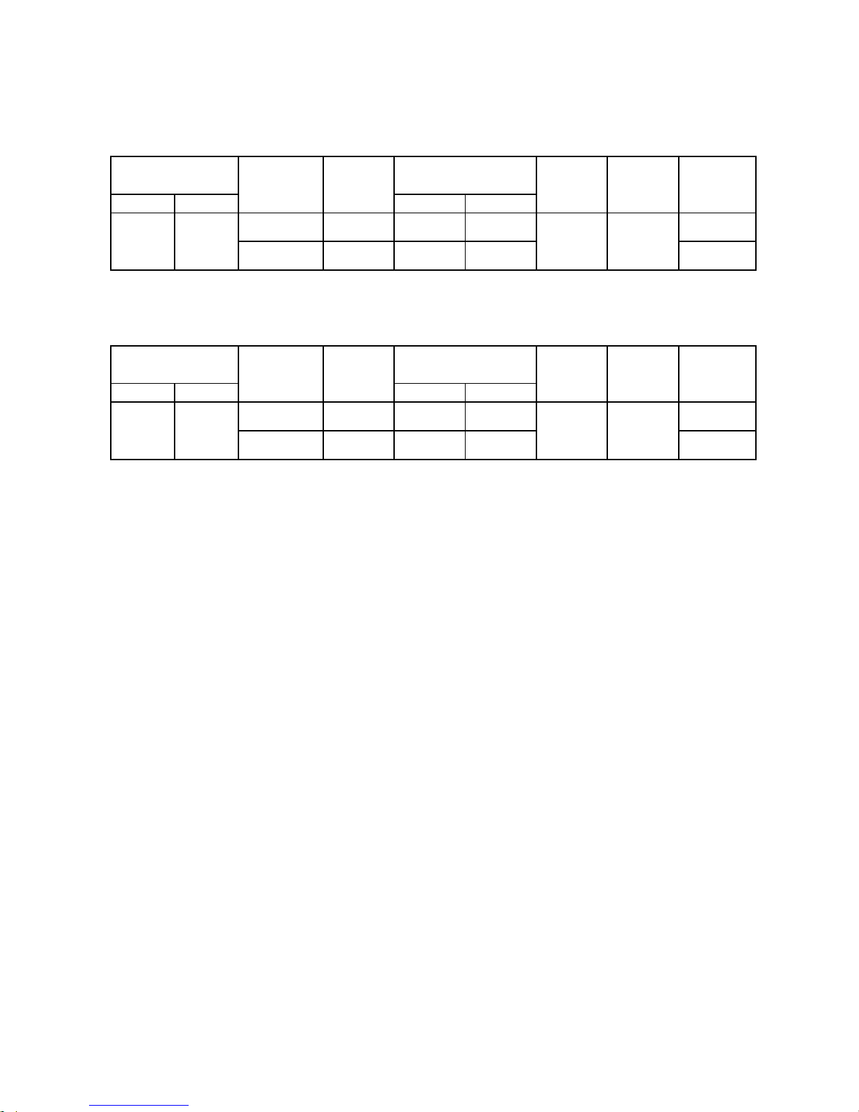
2-1. Specifications
2. SPECIFICATIONS
Unit model Indoor
Outdoor
Cooling capacity (kW)
Cooling capacity range (kW)
Heating capacity (kW)
Heating capacity range (kW)
Power supply
Electric Indoor Operation mode Cooling Heating Cooling Heating
characteristic Running current (220 - 240V) (A) 0.30 - 0.28 0.30 - 0.28 0.38 - 0.35 0.38 - 0.35
Power consumption (W) 40 40 50 50
Power factor (%) 60 60 60 60
Outdoor Operation mode Cooling Heating Cooling Heating
Running current (220 - 240V) (A) 6.35 - 5.82 6.98 - 6.40 9.31 - 8.54 9.56 - 8.77
Power consumption (W) 1380 1520 1945 2000
Power factor (%) 99 99 99 99
Starting current (A)
COP 3.52 3.72 3.01 3.41
Sound Pressure Indoor H/M+/M/L+/L (dB-A)
level Outdoor H (dB-A) 49 50 49 50
Sound power Indoor H/M+/M/L+/L (dB-A)
level Outdoor H (dB-A) 64 65 68 67
Indoor unit Unit model
Dimention Height (mm)
Width (mm)
Depth (mm)
Net weigh (kg)
Fan motor output (W)
Air flow rate (Cooling/Heating)
(m3 / min)
Outdoor unit Unit model
Dimension Height (mm)
Width (mm)
Depth (mm)
Net weigh (kg)
Compressor Motor output (W)
Type
Model
Fan motor output (W)
Air flow rate (Cooling/Heating)
(m3 / min)
Piping Type
connection Indoor unit Liquid side (mm)
Gas side (mm)
Outdoor unit Liquid side (mm)
Gas side (mm)
Maximum length (m)
Maximun chargeless length (m)
Maximum height difference (m)
Refrigerant Name of refrigerant
Weight (kg)
Wiring connection Power supply
Interconnection
Usable temperature range Indoor (Cooling/Heating)
(oC)
Outdoor (Cooling/Heating)
(oC)
Accessary Indoor unit Installation plate
Wireless remote controller
Batteries
Batteries cover
Remote controller holder
Toshiba New IAQ filter (Long)
Mounting screw
Pan head wood screw
Plasma air purifier
Installation instruction
Owner's manual
Outdoor unit Drain nipple
Water-proof rubber cap
* The specification may be subject to change without notice for purpose of improvement.
1
1
1
2
6 (∅4 x 25L)
2 (∅3.1 x 16L), 1 (∅3.1 x 25L)
-
1
1
21~32 / ~28
-10~46 / -15~24
1
1
2
1
∅12.70
20
15
10
R410A
1.40
43
38.6 / 37.2
Flare connection
∅6.35
∅12.70
∅6.35
550
780
290
41
1100
DA150A1F-20F
21~32 / ~28
-10~46 / -15~24
1
1
2
5.0
1.1 - 6.0
5.8
0.8 -6.3
15
10
R410A
1.40
3 Wires: Includes earth (Outdoor)
4 Wires: Includes earth
Flare connection
∅6.35
∅12.70
∅6.35
∅12.70
20
1
550
780
290
39
1100
Twin rotary type with DC-inverter variable speed control
DA131S1B-31FZ
43
RAS-22N3AV2-E
2 2
1
1
1
-
2 (∅3.1 x 16L), 1 (∅3.1 x 25L)
6 (∅4 x 25L)
2
320
1050
243
13
30
18.0 - 18.3
1050
243
13
30
15.9-16.5
RAS-18N3AV2-E
47/44/42/38/3544/41/38/35/32
59/56/53/50/47 62/59/57/53/50
RAS-18N3KV2-E RAS-B22N3KV2-E
RAS-B22N3KV2-E
RAS-22N3AV2-E
1Ph/50Hz/220-240V, 1 Ph/60Hz/220V
- -
6.0
1.2 - 6.7
7.0
1.0 - 7.5
RAS-18N3KV2-E
RAS-18N3AV2-E
320
36.3 / 31.9
– 5 –
– 6 –
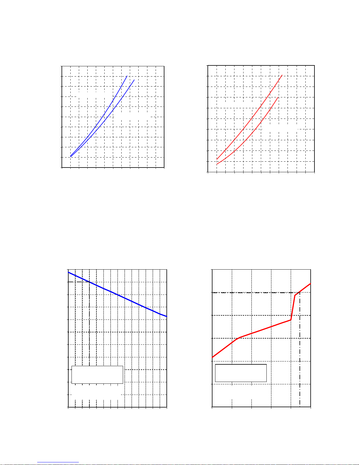
120
100
80
60
40
20
0
Outdoor Temperature (°C)
100
95
90
85
80
75
70
65
60
55
50
105
32 33 34 35 36 37 38 39 40 41 42 43 44 45 46 –15 –10–50 510
Outdoor Temperature (°C)
Capacity Ratio (%)
Capacity Ratio (%)
Condition
Indoor: DB20°C
Indoor Air-Flow Volume: High
Pipe Length: 7.5m
Condition
Indoor: DB27°C/WB19°C
Indoor Air-Flow Volume: High
Pipe Length: 7.5m
2-2. Operation Characteristic Curve
<Cooling> <Heating>
2-3. Capacity Variation Ratio According to Temperature
<Cooling> <Heating>
FILE NO. SVM-12056
0.00
1.00
2.00
3.00
4.00
5.00
6.00
7.00
8.00
9.00
10.00
0 102030405060708090100110120
Compressor Speed (RPS)
Current (A)
0.00
1.00
2.00
3.00
4.00
5.00
6.00
7.00
8.00
9.00
10.00
0 102030405060708090100110120
Compressor Speed (RPS)
Current (A)
RAS-18N3KV2-E
RAS-18N3KV2-E
RAS-B22N3KV2-E
RAS-B22N3KV2-E
Capacity Ratio : 100% =
5.0kW (RAS-18N3KV2-E)
6.0kW (RAS-B22N3KV2-E)
Capacity Ratio : 100% =
5.8kW (RAS-18N3KV2-E)
7.0kW (RAS-B22N3KV2-E)

3. REFRIGERANT R410A
This air conditioner adopts the new refrigerant HFC
(R410A) which does not damage the ozone layer.
The working pressure of the new refrigerant R410A
is 1.6 times higher than conventional refrigerant
(R22). The refrigerating oil is also changed in
accordance with change of refrigerant, so be careful
that water, dust, and existing refrigerant or
refrigerating oil are not entered in the refrigerant
cycle of the air conditioner using the new refrigerant
during installation work or servicing time.
The next section describes the precautions for air
conditioner using the new refrigerant. Conforming
to contents of the next section together with the
general cautions included in this manual, perform
the correct and safe work.
3-1. Safety During Installation/Servicing
As R410A’s pressure is about 1.6 times higher than
that of R22, improper installation/servicing may
cause a serious trouble. By using tools and
materials exclusive for R410A, it is necessary to
carry out installation/servicing safely while taking
the following precautions into consideration.
1. Never use refrigerant other than R410A in an air
conditioner which is designed to operate with
R410A.
If other refrigerant than R410A is mixed,
pressure in the refrigeration cycle becomes
abnormally high, and it may cause personal
injury, etc. by a rupture.
2. Confirm the used refrigerant name, and use
tools and materials exclusive for the refrigerant
R410A.
The refrigerant name R410A is indicated on the
visible place of the outdoor unit of the air conditioner using R410A as refrigerant. To prevent
mischarging, the diameter of the service port
differs from that of R22.
3. If a refrigeration gas leakage occurs during
installation/servicing, be sure to ventilate fully.
If the refrigerant gas comes into contact with fire,
a poisonous gas may occur.
4. When installing or removing an air conditioner,
do not allow air or moisture to remain in the
refrigeration cycle. Otherwise, pressure in the
refrigeration cycle may become abnormally high
so that a rupture or personal injury may be
caused.
5. After completion of installation work, check to
make sure that there is no refrigeration gas
leakage.
If the refrigerant gas leaks into the room, coming
into contact with fire in the fan-driven heater,
space heater, etc., a poisonous gas may occur.
6. When an air conditioning system charged with a
large volume of refrigerant is installed in a small
room, it is necessary to exercise care so that,
even when refrigerant leaks, its concentration
does not exceed the marginal level.
If the refrigerant gas leakage occurs and its
concentration exceeds the marginal level, an
oxygen starvation accident may result.
7. Be sure to carry out installation or removal
according to the installation manual.
Improper installation may cause refrigeration
trouble, water leakage, electric shock, fire, etc.
8. Unauthorized modifications to the air conditioner
may be dangerous.
If a breakdown occurs please call a qualified air
conditioner technician or electrician.
Improper repair may result in water leakage,
electric shock and fire, etc.
3-2. Refrigerant Piping Installation
3-2-1. Piping Materials and Joints Used
For the refrigerant piping installation, copper pipes
and joints are mainly used.
Copper pipes and joints suitable for the refrigerant
must be chosen and installed.
Furthermore, it is necessary to use clean copper
pipes and joints whose interior surfaces are less
affected by contaminants.
1. Copper Pipes
It is necessary to use seamless copper pipes
which are made of either copper or copper alloy
and it is desirable that the amount of residual oil
is less than 40 mg/10 m.
Do not use copper pipes having a collapsed,
deformed or discolored portion
(especially on the interior surface).
Otherwise, the expansion valve or capillary tube
may become blocked with contaminants.
As an air conditioner using R410A incurs pressure higher than when using R22, it is necessary
to choose adequate materials.
Thicknesses of copper pipes used with R410A
are as shown in Table 3-2-1.
Never use copper pipes thinner than 0.8 mm
even when it is available on the market.
FILE NO. SVM-12056
– 7 –

Table 3-2-1 Thicknesses of annealed copper pipes
2. Joints
For copper pipes, flare joints or socket joints are used. Prior to use, be sure to remove all contaminants.
a) Flare Joints
Flare joints used to connect the copper pipes cannot be used for pipings whose outer diameter exceeds
20 mm. In such a case, socket joints can be used.
Sizes of flare pipe ends, flare joint ends and flare nuts are as shown in Tables 3-2-3 to 3-2-6 below.
b) Socket Joints
Socket joints are such that they are brazed for connections, and used mainly for thick pipings whose
diameter is larger than 20 mm.
Thicknesses of socket joints are as shown in Table 3-2-2.
Table 3-2-2 Minimum thicknesses of socket joints
3-2-2. Processing of Piping Materials
When performing the refrigerant piping installation, care should be taken to ensure that water or dust does not
enter the pipe interior, that no other oil than lubricating oils used in the installed air-water heat pump is used,
and that refrigerant does not leak.
When using lubricating oils in the piping processing, use such lubricating oils whose water content has been
removed. When stored, be sure to seal the container with an airtight cap or any other cover.
1. Flare processing procedures and precautions
a) Cutting the Pipe
By means of a pipe cutter, slowly cut the pipe so that it is not deformed.
b) Removing Burrs and Chips
If the flared section has chips or burrs, refrigerant leakage may occur.
Carefully remove all burrs and clean the cut surface before installation.
c) Insertion of Flare Nut
Nominal diameter
1/4
3/8
1/2
5/8
Outer diameter (mm)
6.35
9.52
12.70
15.88
Thickness (mm)
R410A R22
0.80 0.80
0.80 0.80
0.80 0.80
1.00 1.00
Nominal diameter
1/4
3/8
1/2
5/8
Reference outer diameter of
copper pipe jointed (mm)
6.35
9.52
12.70
15.88
Minimum joint thickness
(mm)
0.50
0.60
0.70
0.80
FILE NO. SVM-12056
– 8 –
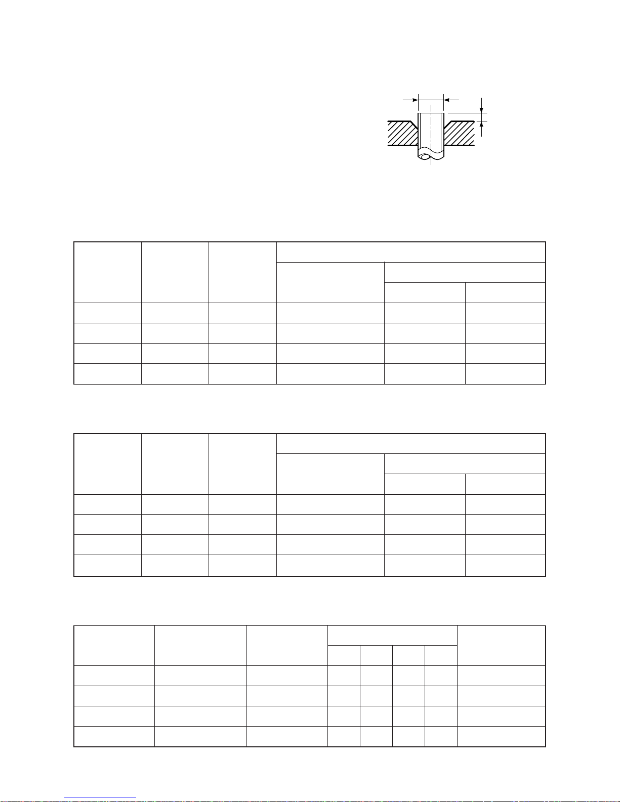
A
ØD
d) Flare Processing
Make certain that a clamp bar and copper
pipe have been cleaned.
By means of the clamp bar, perform the flare
processing correctly.
Use either a flare tool for R410A or conventional flare tool.
Flare processing dimensions differ according
to the type of flare tool.
When using a conventional flare tool, be sure
to secure “dimension A” by using a gauge for
size adjustment.
Fig. 3-2-1 Flare processing dimensions
Table 3-2-3 Dimensions related to flare processing for R410A
Table 3-2-4 Dimensions related to flare processing for R22
Table 3-2-5 Flare and flare nut dimensions for R410A
Nominal
Outer
Thickness
diameter
diameter
(mm)
(mm)
1/4 6.35 0.8
3/8 9.52 0.8
1/2 12.70 0.8
5/8 15.88 1.0
A (mm)
Flare tool for R22
clutch type
0 to 0.5
0 to 0.5
0 to 0.5
0 to 0.5
Conventional flare tool
Clutch type Wing nut type
0.5 to 1.0 1.0 to 1.5
0.5 to 1.0 1.0 to 1.5
0.5 to 1.0 1.5 to 2.0
0.5 to 1.0 1.5 to 2.0
Nominal Outer diameter Thickness
diameter (mm) (mm)
1/4 6.35 0.8
3/8 9.52 0.8
1/2 12.70 0.8
5/8 15.88 1.0
Dimension (mm)
ABCD
9.1 9.2 6.5 13
13.2 13.5 9.7 20
16.0 16.6 12.9 23
19.0 19.7 16.0 25
Flare nut width
(mm)
17
22
26
29
Conventional flare tool
Clutch type Wing nut type
1.0 to 1.5 1.5 to 2.0
1.0 to 1.5 1.5 to 2.0
1.0 to 1.5 2.0 to 2.5
1.0 to 1.5 2.0 to 2.5
Nominal
Outer
Thickness
diameter
diameter
(mm)
(mm)
1/4 6.35 0.8
3/8 9.52 0.8
1/2 12.70 0.8
5/8 15.88 1.0
A (mm)
Flare tool for R410A
clutch type
0 to 0.5
0 to 0.5
0 to 0.5
0 to 0.5
FILE NO. SVM-12056
– 9 –
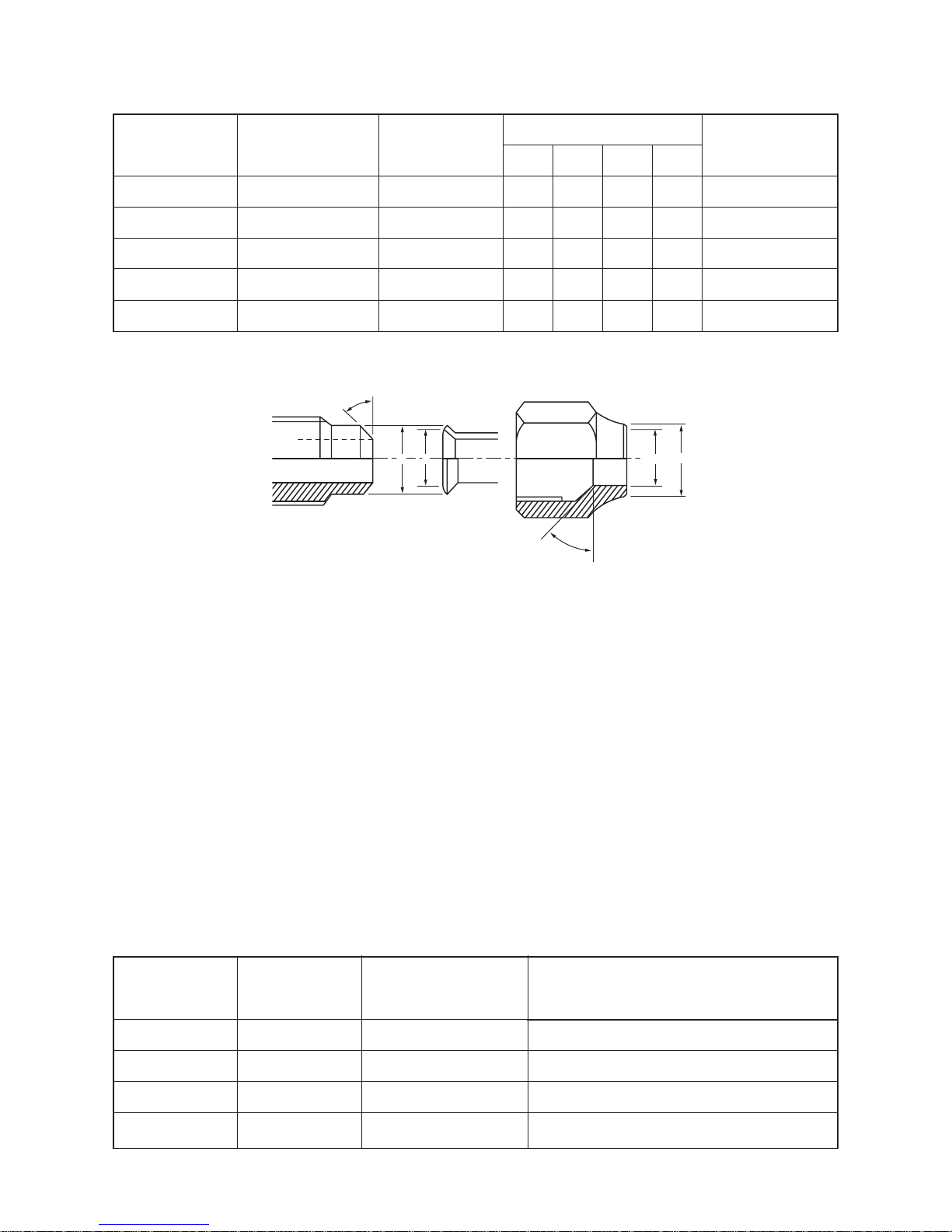
Table 3-2-6 Flare and flare nut dimensions for R22
Fig. 3-2-2 Relations between flare nut and flare seal surface
2. Flare Connecting Procedures and Precautions
a) Make sure that the flare and union portions do not have any scar or dust, etc.
b) Correctly align the processed flare surface with the union axis.
c) Tighten the flare with designated torque by means of a torque wrench.
The tightening torque for R410A is the same as that for conventional R22.
Incidentally, when the torque is weak, the gas leakage may occur.
When it is strong, the flare nut may crack and may be made non-removable.
When choosing the tightening torque, comply with values designated by manufacturers.
Table 3-2-7 shows reference values.
NOTE :
When applying oil to the flare surface, be sure to use oil designated by the manufacturer.
If any other oil is used, the lubricating oils may deteriorate and cause the compressor to burn out.
Table 3-2-7 Tightening torque of flare for R410A [Reference values]
Nominal Outer diameter Thickness
diameter (mm) (mm)
1/4 6.35 0.8
3/8 9.52 0.8
1/2 12.70 0.8
5/8 15.88 1.0
3/4 19.05 1.0
Dimension (mm)
ABCD
9.0 9.2 6.5 13
13.0 13.5 9.7 20
16.0 16.2 12.9 20
19.0 19.7 16.0 23
23.3 24.0 19.2 34
Flare nut width
(mm)
17
22
24
27
36
43˚ to 45˚
45˚ to 46˚
B A
C
D
Tightening torque of
torque wrenches available on the market
N•m (kgf•cm)
16 (160), 18 (180)
42 (420)
55 (550)
65 (650)
Nominal
Outer
Tightening torque
diameter
diameter
(mm)
N•m (kgf•cm)
1/4 6.35 14 to 18 (140 to 180)
3/8 9.52 33 to 42 (330 to 420)
1/2 12.70 50 to 62 (500 to 620)
5/8 15.88 63 to 77 (630 to 770)
FILE NO. SVM-12056
– 10 –
1. Vacuum pump
Use vacuum pump by attaching
vacuum pump adapter.
2. Torque wrench (For Ø6.35, Ø9.52)
3. Pipe cutter
4. Reamer
5. Pipe bender
6. Level vial
7. Screwdriver (+, –)
8. Spanner or Monkey wrench
9. Hole core drill (Ø65)
10. Hexagon wrench
(Opposite side 4mm)
11. Tape measure
12. Metal saw
Also prepare the following equipments for other installation method and run check.
1. Clamp meter
2. Thermometer
3. Insulation resistance tester
4. Electroscope
3-3. Tools
3-3-1. Required Tools
The service port diameter of packed valve of the outdoor unit in the air-water heat pump using R410A is
changed to prevent mixing of other refrigerant.
To reinforce the pressure-resisting strength, flare processing dimensions and opposite side dimension of flare
nut (For Ø12.7 copper pipe) of the refrigerant piping are lengthened.
The used refrigerating oil is changed, and mixing of oil may cause a trouble such as generation of sludge,
clogging of capillary, etc. Accordingly, the tools to be used are classified into the following three types.
1. Tools exclusive for R410A (Those which cannot be used for conventional refrigerant (R22))
2. Tools exclusive for R410A, but can be also used for conventional refrigerant (R22)
3. Tools commonly used for R410A and for conventional refrigerant (R22)
The table below shows the tools exclusive for R410A and their interchangeability.
Tools exclusive for R410A (The following tools for R410A are required.)
Tools whose specifications are changed for R410A and their interchangeability
(Note 1) When flaring is carried out for R410A using the conventional flare tools, adjustment of projection
margin is necessary. For this adjustment, a copper pipe gauge, etc. are necessary.
(Note 2) Charging cylinder for R410A is being currently developed.
General tools (Conventional tools can be used.)
In addition to the above exclusive tools, the following equipments which serve also for R22 are necessary as the general tools.
No.
1
2
3
4
5
6
7
8
9
10
Used tool
Flare tool
Copper pipe gauge
for adjusting
projection margin
Torque wrench
(For Ø12.7)
Gauge manifold
Charge hose
Vacuum pump
adapter
Electronic balance for
refrigerant charging
Refrigerant cylinder
Leakage detector
Charging cylinder
Usage
Pipe flaring
Flaring by
conventional flare tool
Connection of flare nut
Evacuating, refrigerant
charge, run check, etc.
Vacuum evacuating
Refrigerant charge
Refrigerant charge
Gas leakage check
Refrigerant charge
R410A
air-water heat pump installation
Existence of Whether conventional
new equipment equipment can be
for R410A used
Ye s ∗ (Note 1)
Ye s ∗ (Note 1)
Ye s N o
Ye s N o
Ye s N o
Ye s N o
Ye s N o
Ye s N o
∗ (Note 2) No
Conventional air-water
heat pump installation
Whether new equipment
can be used with
conventional refrigerant
Ye s
∗ (Note 1)
No
No
Ye s
Ye s
No
Ye s
No
FILE NO. SVM-12056
– 11 –
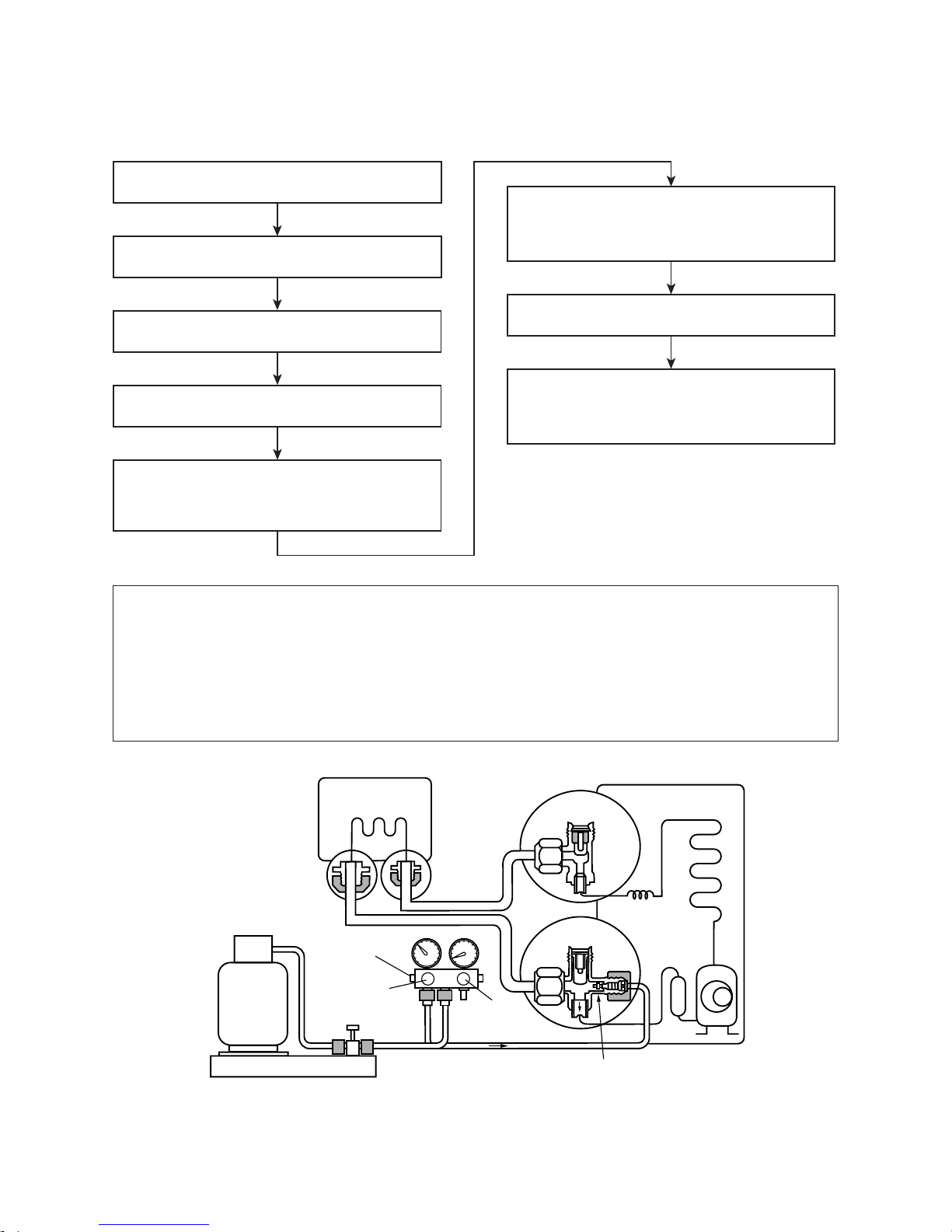
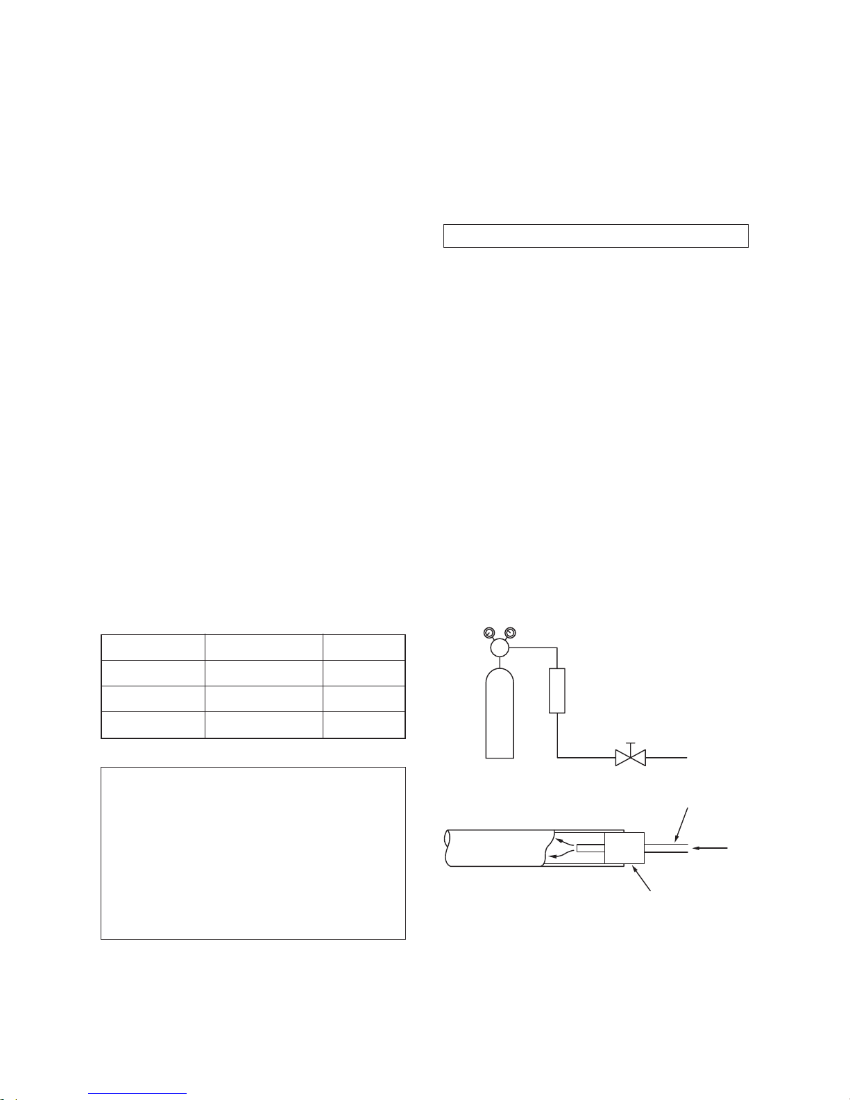
Connect the charge hose to packed valve service
port at the outdoor unit’s gas side.
Recover the refrigerant, and check no refrigerant
remains in the equipment.
(For refrigerant charging, see the figure below.)
Connect the charge hose to the vacuum pump
adapter.
Open fully both packed valves at liquid and gas
sides.
Place the handle of the gauge manifold Low in the
fully opened position, and turn on the vacuum pump’s
power switch. Then, evacuating the refrigerant in the
cycle.
When the compound gauge’s pointer has indicated
–0.1 Mpa (–76 cmHg), place the handle Low in the
fully closed position, and turn off the vacuum pump’s
power switch.
Keep the status as it is for 1 to 2 minutes, and ensure
that the compound gauge’s pointer does not return.
Set the refrigerant cylinder to the electronic balance,
connect the connecting hose to the cylinder and the
connecting port of the electronic balance, and charge
liquid refrigerant.
(Indoor unit)
(Outdoor unit)
Opened
Opened
Refrigerant cylinder
(with siphon)
Check valve
Open/close
valve for charging
Electronic balance for refrigerant charging
Opened
Closed
Service port
3-4. Recharging of Refrigerant
When it is necessary to recharge refrigerant, charge the specified amount of new refrigerant according to the
following steps.
1. Never charge refrigerant exceeding the specified amount.
2. If the specified amount of refrigerant cannot be charged, charge refrigerant bit by bit in COOL mode.
3. Do not carry out additional charging.
When additional charging is carried out if refrigerant leaks, the refrigerant composition changes in the
refrigeration cycle, that is characteristics of the air conditioner changes, refrigerant exceeding the
specified amount is charged, and working pressure in the refrigeration cycle becomes abnormally high
pressure, and may cause a rupture or personal injury.
Fig. 3-4-1 Configuration of refrigerant charging
FILE NO. SVM-12056
– 12 –
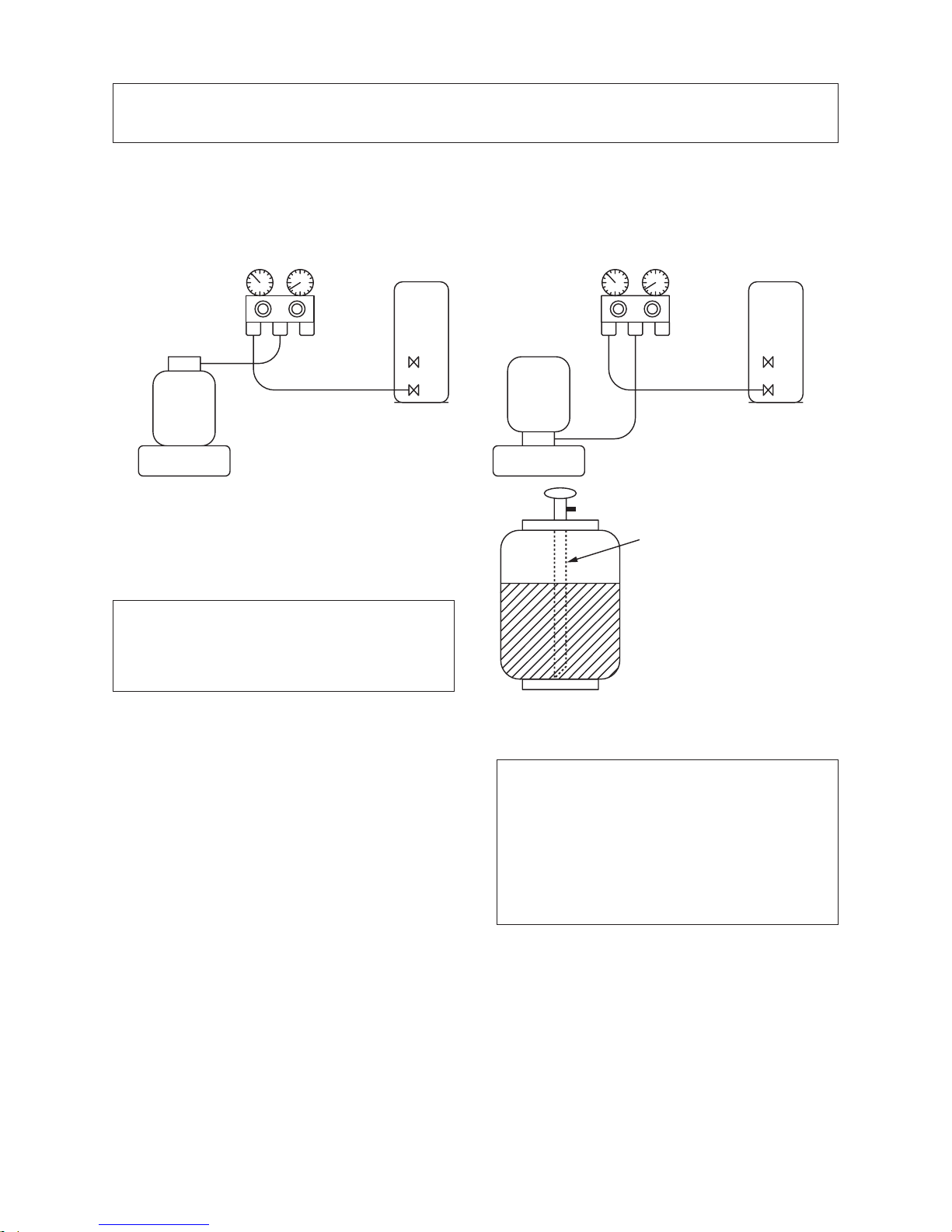
Gauge manifold
[ Cylinder with siphon ] [ Cylinder without siphon ]
OUTDOOR unit
Gauge manifold
OUTDOOR unit
Refrigerant
cylinder
Electronic
balance
Refrigerant
cylinder
Electronic
balance
Siphon
1. Be sure to make setting so that liquid can be charged.
2. When using a cylinder equipped with a siphon, liquid can be charged without turning it upside down.
It is necessary for charging refrigerant under condition of liquid because R410A is mixed type of refrigerant.
Accordingly, when charging refrigerant from the refrigerant cylinder to the equipment, charge it turning the
cylinder upside down if cylinder is not equipped with siphon.
R410A refrigerant is HFC mixed refrigerant.
Therefore, if it is charged with gas, the composition of the charged refrigerant changes and the
characteristics of the equipment varies.
3-5. Brazing of Pipes
3-5-1. Materials for Brazing
1. Silver brazing filler
Silver brazing filler is an alloy mainly composed
of silver and copper. It is used to join iron, copper
or copper alloy, and is relatively expensive
though it excels in solderability.
2. Phosphor bronze brazing filler
Phosphor bronze brazing filler is generally used
to join copper or copper alloy.
3. Low temperature brazing filler
Low temperature brazing filler is generally called
solder, and is an alloy of tin and lead.
Since it is weak in adhesive strength, do not use
it for refrigerant pipes.
1. Phosphor bronze brazing filler tends to react
with sulfur and produce a fragile compound
water solution, which may cause a gas
leakage. Therefore, use any other type of
brazing filler at a hot spring resort, etc., and
coat the surface with a paint.
2. When performing brazing again at time of
servicing, use the same type of brazing filler.
3-5-2. Flux
1. Reason why flux is necessary
• By removing the oxide film and any foreign
matter on the metal surface, it assists the flow
of brazing filler.
• In the brazing process, it prevents the metal
surface from being oxidized.
• By reducing the brazing filler’s surface tension,
the brazing filler adheres better to the treated
metal.
Fig. 3-4-2
FILE NO. SVM-12056
– 13 –
Nitrogen gas
cylinder
Pipe
Flow meter
M
Stop valve
From Nitrogen cylinder
Nitrogen gas
Rubber plug
2. Characteristics required for flux
• Activated temperature of flux coincides with
the brazing temperature.
• Due to a wide effective temperature range, flux
is hard to carbonize.
• It is easy to remove slag after brazing.
• The corrosive action to the treated metal and
brazing filler is minimum.
• It excels in coating performance and is harmless to the human body.
As the flux works in a complicated manner as
described above, it is necessary to select an
adequate type of flux according to the type and
shape of treated metal, type of brazing filler and
brazing method, etc.
3. Types of flux
• Noncorrosive flux
Generally, it is a compound of borax and boric
acid.
It is effective in case where the brazing temperature is higher than 800°C.
• Activated flux
Most of fluxes generally used for silver brazing
are this type.
It features an increased oxide film removing
capability due to the addition of compounds
such as potassium fluoride, potassium chloride
and sodium fluoride to the borax-boric acid
compound.
4. Piping materials for brazing and used
brazing filler/flux
1. Do not enter flux into the refrigeration cycle.
2. When chlorine contained in the flux remains
within the pipe, the lubricating oil deteriorates. Therefore, use a flux which does not
contain chlorine.
3. When adding water to the flux, use water
which does not contain chlorine
(e.g. distilled water or ion-exchange water).
4. Remove the flux after brazing.
3-5-3. Brazing
As brazing work requires sophisticated techniques,
experiences based upon a theoretical knowledge, it
must be performed by a person qualified.
In order to prevent the oxide film from occurring in
the pipe interior during brazing, it is effective to
proceed with brazing while letting dry Nitrogen gas
(N2) flow.
Never use gas other than Nitrogen gas.
1. Brazing method to prevent oxidation
1) Attach a reducing valve and a flow-meter to
the Nitrogen gas cylinder.
2) Use a copper pipe to direct the piping material, and attach a flow-meter to the cylinder.
3) Apply a seal onto the clearance between the
piping material and inserted copper pipe for
Nitrogen in order to prevent backflow of the
Nitrogen gas.
4) When the Nitrogen gas is flowing, be sure to
keep the piping end open.
5) Adjust the flow rate of Nitrogen gas so that it
is lower than 0.05 m3/Hr or 0.02 MPa
(0.2kgf/cm2) by means of the reducing valve.
6) After performing the steps above, keep the
Nitrogen gas flowing until the pipe cools down
to a certain extent (temperature at which
pipes are touchable with hands).
7) Remove the flux completely after brazing.
Fig. 3-5-1
Prevention of oxidation during brazing
Piping material
Copper - Copper
Copper - Iron
Iron - Iron
Used brazing filler
Phosphor copper
Silver
Silver
Used flux
Do not use
Paste flux
Vapor flux
FILE NO. SVM-12056
– 14 –
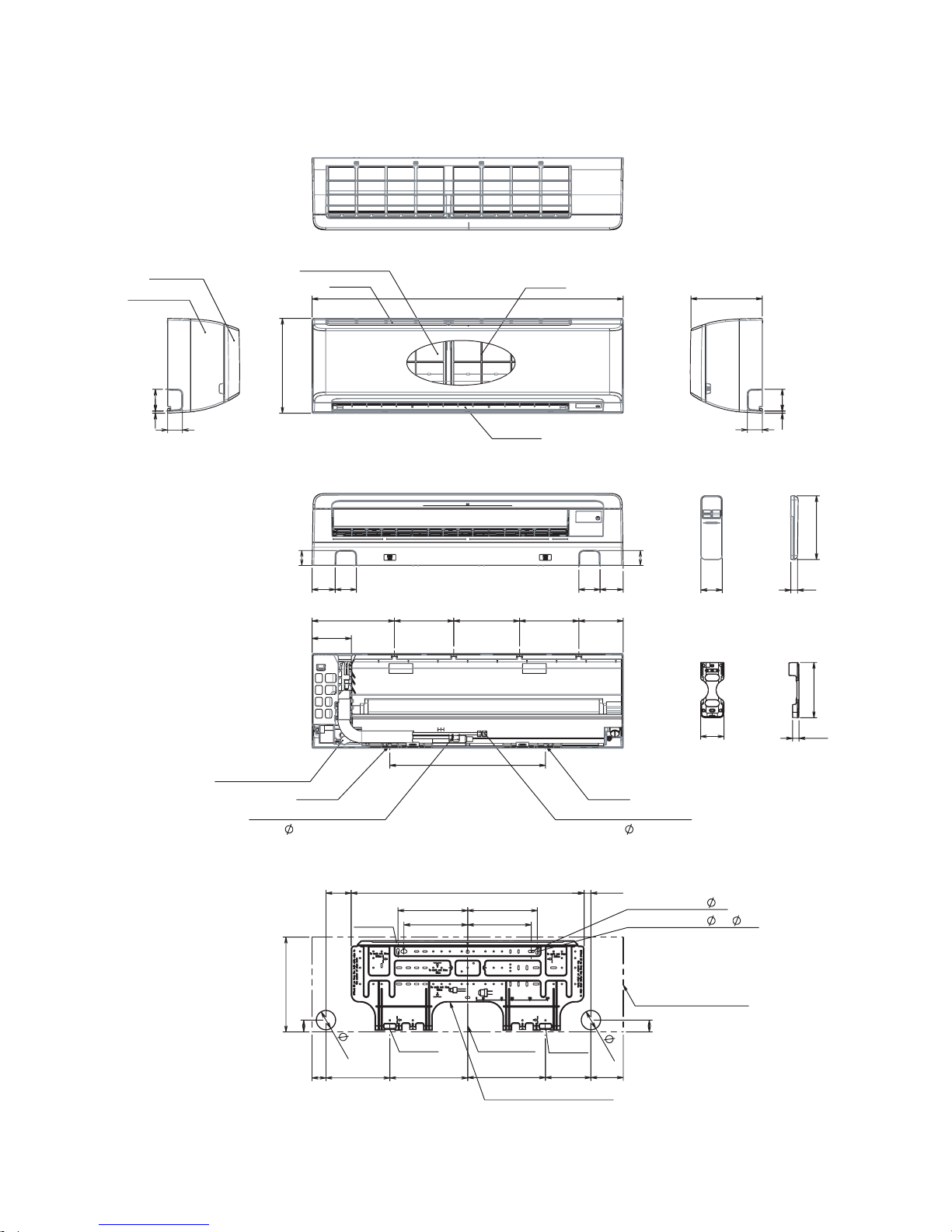
4. CONSTRUCTION VIEWS
4-1. Indoor Unit
FILE NO. SVM-12056
1050
320
Air Inlet
Heat exchanger
Air filter
Air outlet
50
72 78
50
78 72
73.5
50
7
243
50
73.5 7
Knock out system Knock out system
Front Panel
Grille Inlet
132
150 200 222 200 278
525
Drain hose (0.5m)
Hanger Hanger
Connecting pipe (0.39m)
(Flare
6.35)
(Flare
12.70)
Connecting pipe (0.49m)
786
262.5
262.5
235
215 215
235
320
65
40
47
85
65
40
23
109
215.5
153.5
Hanger
Installation plate outline
Hanger
Hanger
Outline of indoor unit
For stud bold (
6)
For stud bold (
8~
10)
Center line
63
Remote controller holder
17.5
149
57
Wireless remote controller
172
18
– 15 –
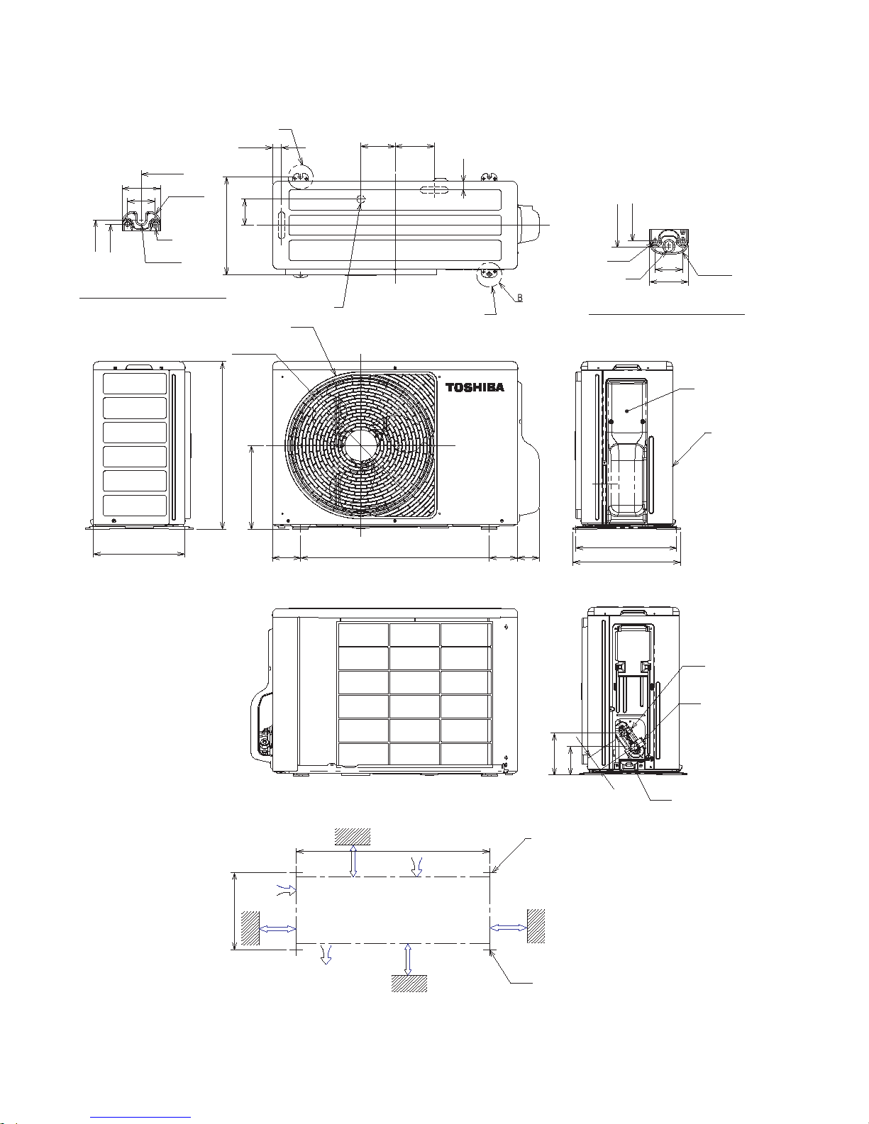
4-2. Outdoor Unit
320
306
80
Z View
600
A detail Drawing (Back leg)
320
306
Ø
25 Drain outlet
11 x 14
Hole
(For 8 -
10 anchor bolt)
B Detail Drawing (Front leg)
FAN-GUARD
COVER-PV
Liquid side
(Flare 6.35)
Ø
(Flare ∅ 12.7)
Gas side
Service port
2 - ∅11 x 14 Long holes (For ∅8- ∅10 anchor bolt)
Installation dimension
Air outlel
100 or more
100 or more
600 or more
600 or more
Air intlel
Ø
Ø
Ø
Ø
6 hole
86
Ø
6 hole
Ø
11x14 hole
R
15
28
A
320
R5.5
36
108 125
50
137
92
5
4
600
320
9060090
275
290
550
Ø
436
Z
R
15
50
36
-
2
320
342
69
2 - R5-5 x 17L Ushape
(For ∅ 8 - ∅10 anchor bolt)
FILE NO. SVM-12056
– 16 –
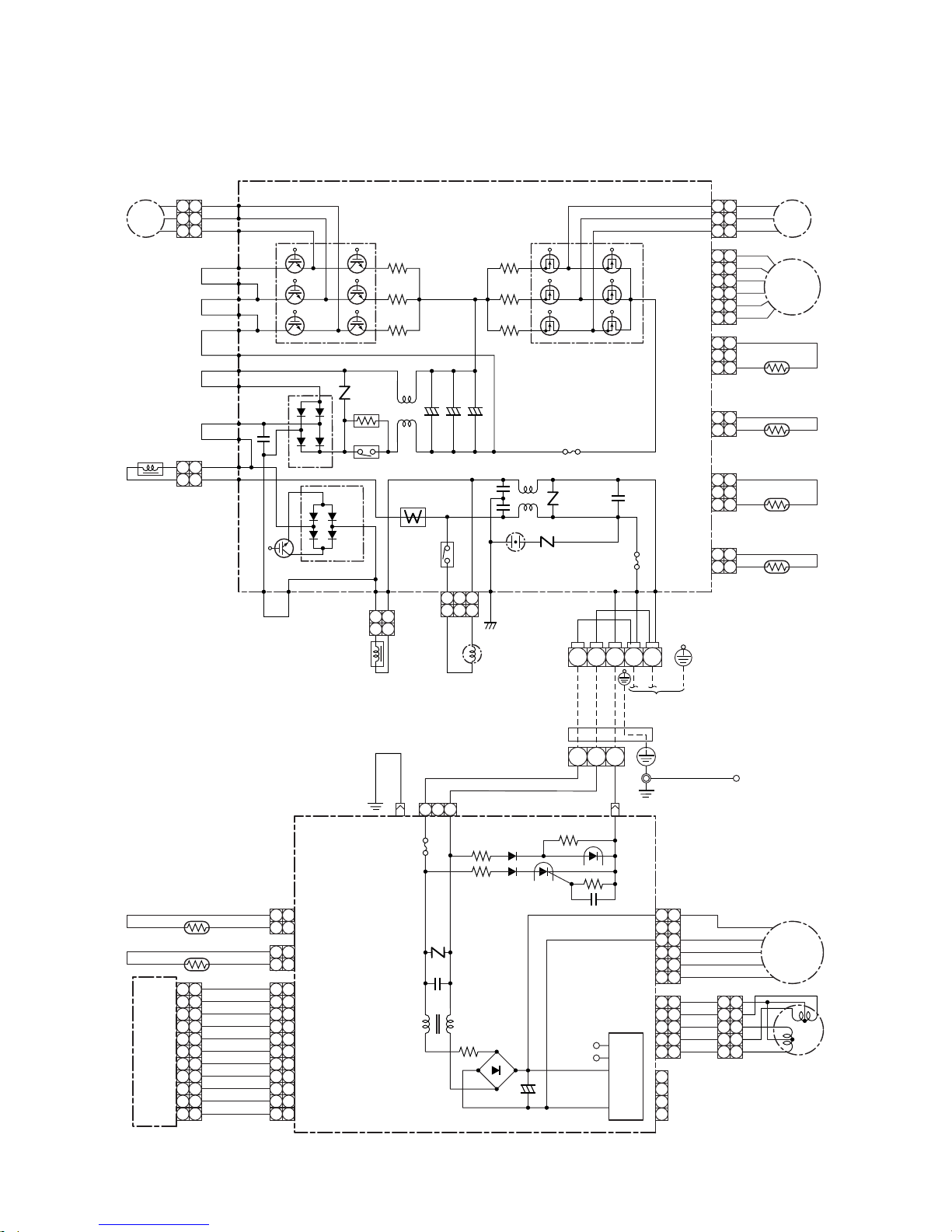
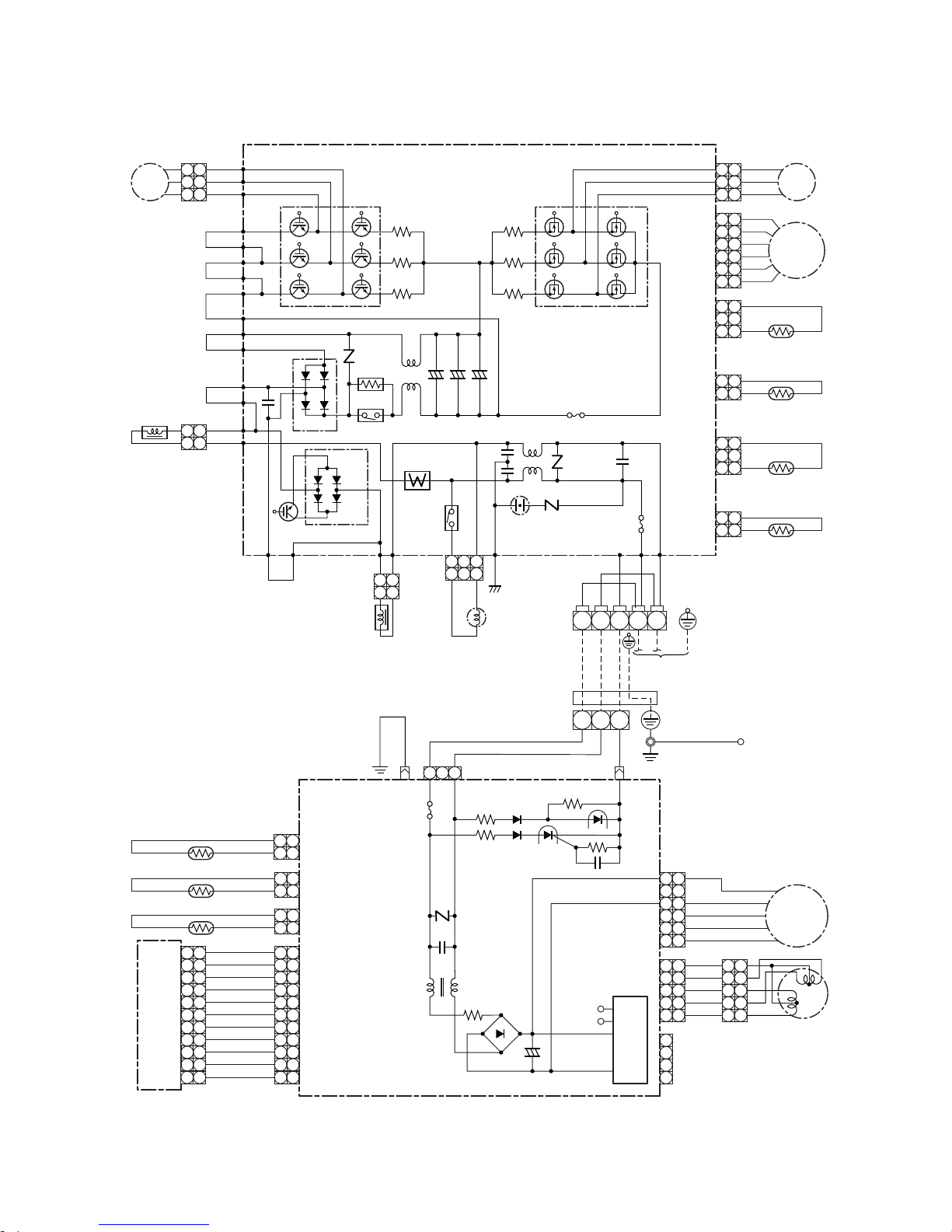
5. WIRING DIAGRAM
5-1. Indoor Unit / Outdoor Unit
P22
Compressor
CM
P. C. Board
MCC-5009
Main P. C. Board
MCC-5045
RED
WHI
BLK
P04
P05
P06
P25
YEL
P24
R221
Q200 ~ 205
IGBT
Q300 ~ 305
MOS-FET
CN300
CN700
CN603
CN602
CN601
CN600
Suction pipe
Temp. Sensor
(TS)
Fan Motor
Pulse Motor Valve
FM
1
2
3
1
2
P11
P08
P32
PUR
P33 P30 BLK
CN701 P07
BLK
ORN WHI
P03
P10
P02
P31
Q404
CT
3
BLU
BLU
BLU
1
2
3
1
2
3
BLU
4 4
BLU
5 5
BLU
6 6
BLU
7 7
BLU
8 8
BLU
9 9
BLU
CN10
(WHI)
CN61
(WHI)
10 10
1
2
3
1
2
3
4 4
5 5
6 6
7 7
8 8
9 9
CN21
(WHI)
10 10
BLK
WHI
RED
3
2
1
3
2
1
6
5
4
6
5
4
3 3
2 2
1 1
3
2
1
3
2
1
P23
YEL
P34
P35 L03
L01
Varistor
Varistor
Varistor
Line Filter
Surge
Absorber
F01 Fuse
250V ~, T25A
Power Relay
Relay
DB01
DB02
C12 C14
C13
YEL
P21
BRW
P20
R220
R219
PMV
Discharge pipe
Temp. Sensor
(TD)
3
2
1
3
2
1
Condenser pipe
Temp. Sensor
(TE)
212
1
Thermo Sensor (TA)
121
2
CN62
(BLU)
Heat Exchanger Sensor (TC)
121
2
CN01CN02 CN51
Outdoor
Temp. Sensor
(TO)
212
1
R321
R320
R319
P19
P18
Reactor
Reactor
Coil for
4-way Valve
Indoor Terminal Block
Wireless Unit Assembly
WP-027
ORN
+ + +
121
2
112
2
11223
3
F03 Fuse
250V ~, T3.15A
NL321
WHI
YEL
YEL
1
2
3
1
2
3
YEL
4
1
2
3
4
4
YEL
5 5
CN22
(WHI)
CN32
(WHI)
CN31
(WHI)
Louver Motor
Fan Motor
1
2
3
1
2
3
4 4
5 5
1
2
3
1
2
3
4 4
BLK
BLK
Sheet
Metal
WHI
RED
5 5
GRN & YEL
Heat Exchanger
6 6
WHI
11 11 11 11
DC Motor
Power Supply
Circuit
DC5V
DC12V
113
+
F01 Fuse
T3.15A
AC 250V
+
~
~
321
N
FILE NO. SVM-12056
Power Supply
(From Main Line)
RAS-18N3KV2-E / RAS-18N3AV2-E
– 17 –
FILE NO. SVM-12056
RAS-B22N3KV2-E / RAS-22N3AV2-E
P22
Compressor
CM
P. C. Board
MCC-5009
Main P. C. Board
MCC-5045
RED
WHI
BLK
P04
P05
P06
P25
YEL
P24
R221
Q200 ~ 205
IGBT
Q300 ~ 305
MOS-FET
CN300
CN700
CN603
CN602
CN601
CN600
Suction pipe
Temp. Sensor
(TS)
Fan Motor
Pulse Motor Valve
FM
1
2
3
1
2
P11
P08
P32
PUR
P33 P30 BLK
CN701 P07
BLK
ORN WHI
P03
P10
P02
P31
Q404
CT
3
BLU
BLU
BLU
1
2
3
1
2
3
BLU
4 4
BLU
5 5
BLU
6 6
BLU
7 7
BLU
8 8
BLU
9 9
BLU
CN10
(WHI)
CN61
(WHI)
10 10
1
2
3
1
2
3
4 4
5 5
6 6
7 7
8 8
9 9
CN21
(WHI)
10 10
BLK
WHI
RED
3
2
1
3
2
1
6
5
4
6
5
4
3 3
2 2
1 1
3
2
1
3
2
1
P23
YEL
P34
P35 L03
L01
Varistor
Varistor
Varistor
Line Filter
Surge
Absorber
F01 Fuse
250V ~, T25A
Power Relay
Relay
DB01
DB02
C12 C14
C13
YEL
P21
BRW
P20
R220
R219
PMV
Discharge pipe
Temp. Sensor
(TD)
3
2
1
3
2
1
Condenser pipe
Temp. Sensor
(TE)
212
1
Thermo Sensor (TA)
121
2
CN62
(BLU)
Heat Exchanger Sensor (TC)
121
2
CN01CN02 CN51
Outdoor
Temp. Sensor
(TO)
212
1
R321
R320
R319
P19
P18
Reactor
Reactor
Coil for
4-way Valve
Indoor Terminal Block
Wireless Unit Assembly
WP-027
ORN
+ + +
121
2
112
2
11223
3
F03 Fuse
250V ~, T3.15A
NL321
WHI
YEL
YEL
1
2
3
1
2
3
YEL
4
1
2
3
4
4
YEL
5 5
CN22
(WHI)
CN32
(WHI)
CN31
(WHI)
Louver Motor
Fan Motor
1
2
3
1
2
3
4 4
5 5
1
2
3
1
2
3
4 4
BLK
BLK
Sheet
Metal
WHI
RED
5 5
GRN & YEL
Heat Exchanger
6 6
WHI
11 11 11 11
DC Motor
Power Supply
Circuit
DC5V
DC12V
113
+
F01 Fuse
T3.15A
AC 250V
+
~
~
321
N
Power Supply
(From Main Line)
CN63
(YEL)
Heat Exchanger Sensor (TCJ)
121
2
– 18 –
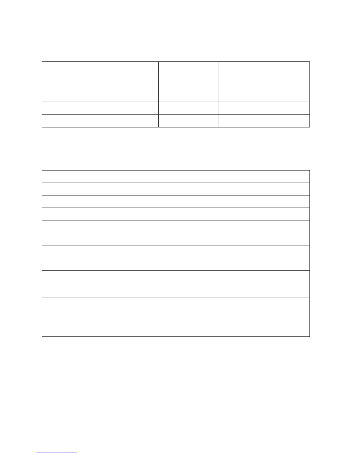
6. SPECIFICATIONS OF ELECTRICAL PARTS
6-1. Indoor Unit
6-2. Outdoor Unit
No.
1
2
3
4
Room temp. sensor (TA-sensor)
Heat exchanger temp. sensor (TC-sensor)
Louver motor
MF-340-30-3
( — )
( — )
MSBPC20F04
DC340V, 30W
10kΩ at 25°C
10kΩ at 25°C
DC12V, 4phase, 16pole
No.
1
2
3
4
5
6
Parts name
Reactor
Outdoor fan motor
Suction temp. sensor (TS sensor)
Discharge temp. sensor (TD sensor)
Outside air temp. sensor (TO sensor)
Heat exchanger temp. sensor (TE sensor)
Model name
CH-57-Z-T
ICF-140-43-4R
(Inverter attached)
(Inverter attached)
(Inverter attached)
(Inverter attached)
L = 10mH, 16A
DC140V, 43W
10kΩ (25°C)
62kΩ (20°C), 3.3kΩ (100°C)
10kΩ (25°C)
10kΩ (25°C)
7
8
9
10
DA150A1F-20F
CAM-MD12TCTH-5
Rating
20A, AC250V
3phases 4poles 1100W
DC12V
AC220–240V
Terminal block (5P)
Compressor
Coil for PMV
Coil for 4-way valve
JXO-5B
RAS-18N3AV2-E
RAS-22N3AV2-E
DA131S1B-31FZ
RAS-18N3AV2-E
RAS-22N3AV2-E
STF-01AJ646A1
STF-01AJ503K1
FILE NO. SVM-12056
– 19 –
Parts name Model name
Rating
Fan motor (for indoor)
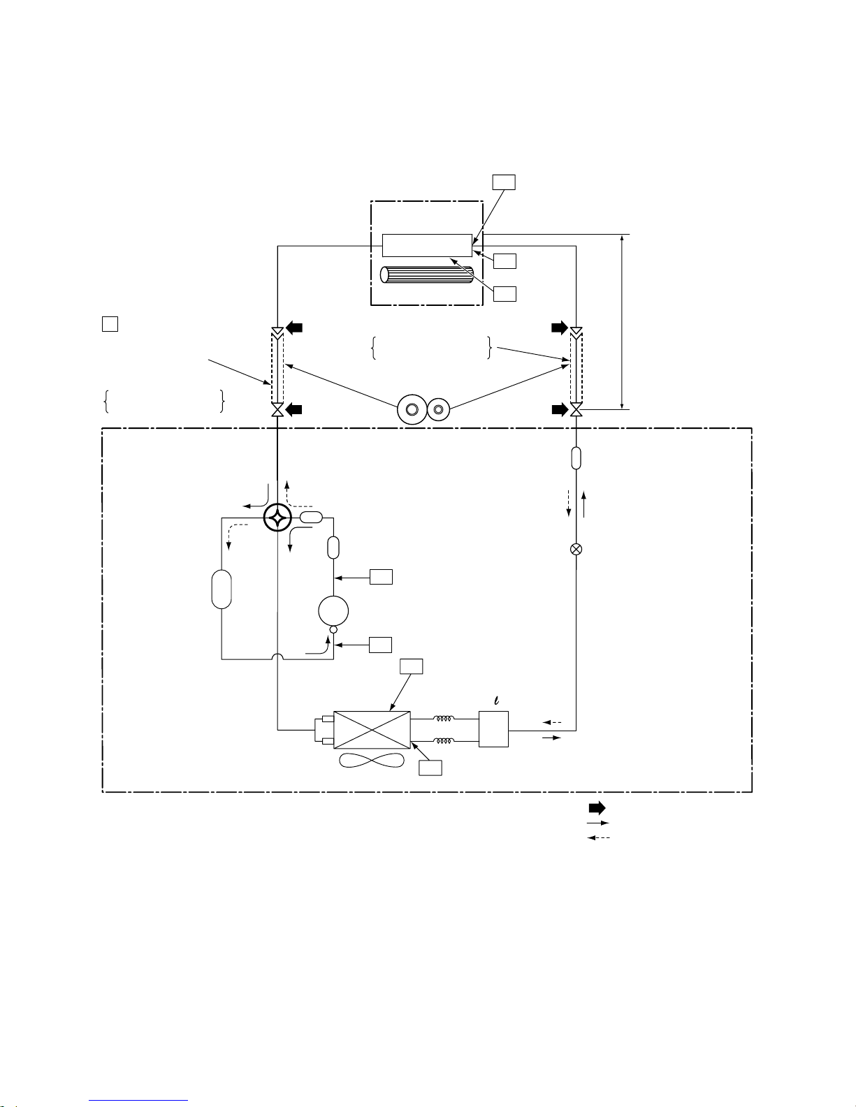
NOTE :
• The maximum pipe length of this air conditioner is 20m. When the pipe length exceeds 15m, the additional
charging of refrigerant, 20g per 1m for the part of pipe exceeded 15m is required. (Max. 100g)
Max. : 20m
Min. : 2m
Chargeless : 15m
Charge : 20g/m
(16 to 20m)
Deoxidized copper pipe
Outer dia. : 12.7mm
Thickness : 0.8mm
NOTE:
Gas leak check position
Refrigerant flow (Cooling)
Refrigerant flow (Heating)
INDOOR UNIT
T1 Temp. measurement
Indoor heat
exchanger
Cross flow fan
Sectional shape
of heat insulator
Allowable height
difference: 10m
Allowable pipe length
P
Pressure measurement
Gauge attaching port
Vacuum pump connecting port
Strainer
Pulse Modulating valve
at liquid side
(CAM-
BD16TCTH-2)
TD
4-way valve
(STF-0108-Z)
Compressor
DA131S1B-31FZ
Propeller fan
Refrigerant amount: 1.40kg
OUTDOOR UNIT
TC
TA
Outdoor heat
exchanger
Split capillary
2-dia. 1.2 × 80
TE
Muffler
Muffler
Accumulater tank
Deoxidized copper pipe
Outer dia. : 6.35mm
Thickness : 0.8mm
TS
TO
Distributor
FILE NO. SVM-12056
7. REFRIGERANT CYCLE DIAGRAM
7-1. Refrigerant Cycle Diagram
RAS-18N3KV2-E / RAS-18N3AV2-E
– 20 –
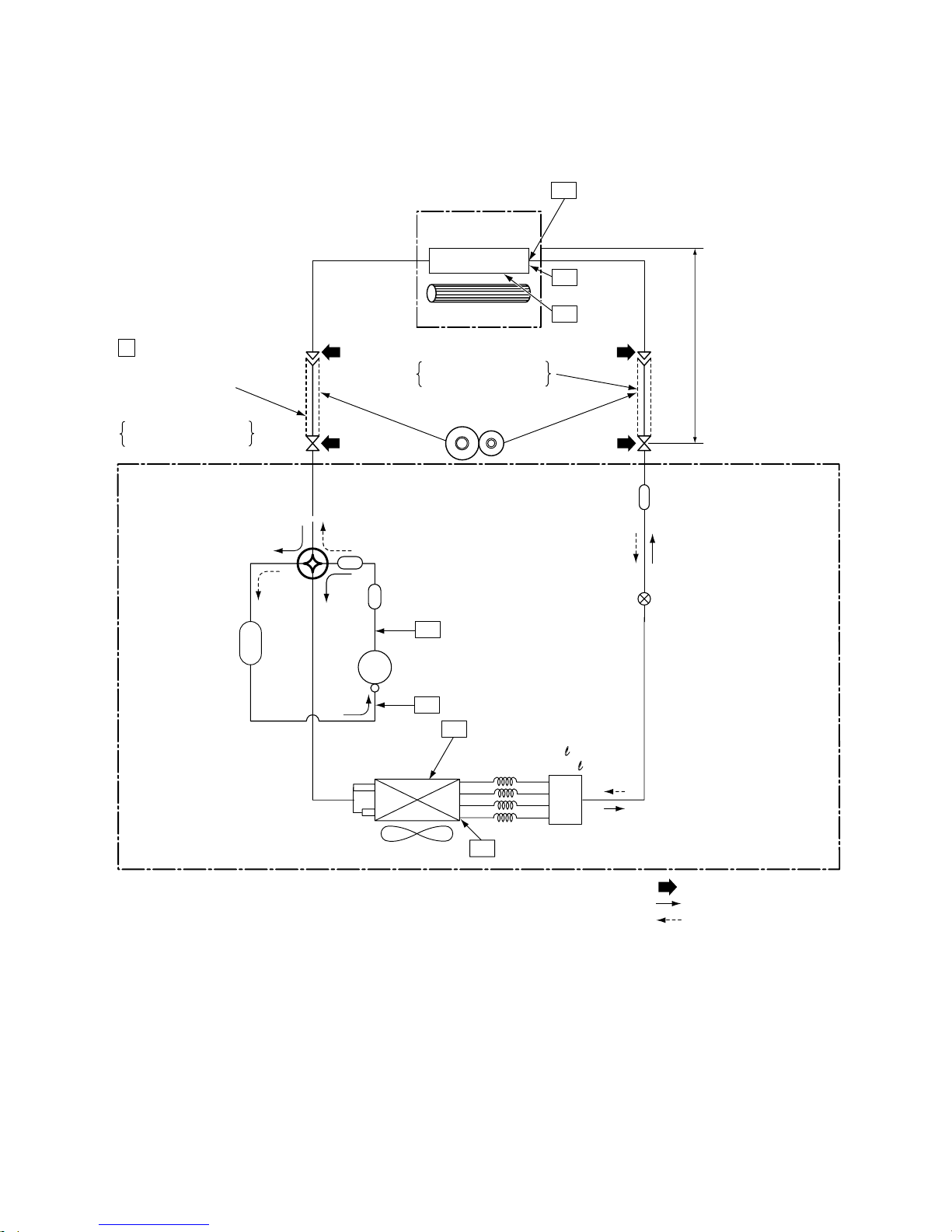
FILE NO. SVM-12056
NOTE :
• The maximum pipe length of this air conditioner is 15m. When the pipe length exceeds 15m, the additional
charging of refrigerant, 20g per 1m for the part of pipe exceeded 15m is required. (Max. 100g)
Strainer
TE
Max. : 20m
Min. : 2m
Chargeless : 15m
Charge : 20g/m
(16 to 20m)
Allowable height
difference: 10m
Allowable pipe length
Pulse Modulating valve
at liquid side
(CAM-BD16TCTH-2)
NOTE:
Gas leak check position
Refrigerant flow (Cooling)
Refrigerant flow (Heating)
OUTDOOR UNIT
INDOOR UNIT
T1 Temp. measurement
Indoor heat
exchanger
Cross flow fan
TC
TA
Deoxidized copper pipe
Outer dia. : 12.7mm
Thickness : 0.8mm
Sectional shape
of heat insulator
P
Pressure measurement
Gauge attaching port
Vacuum pump connecting port
Deoxidized copper pipe
Outer dia. : 6.35mm
Thickness : 0.8mm
TD
4-way valve
(STF-
0213-Z)
Compressor
DA150A1F-20F
Muffler
Muffler
Accumulater tank
TS
Propeller fan
Outdoor heat
exchanger
TO
Distributor
RAS-B22N3KV2-E / RAS-22N3AV2-E
1 -dia. 2 × 100
2 - 4 -dia. 2 × 66
Split capillary
1
2
3
4
Refrigerant amount: 1.40kg
– 21 –
7-2. Operation Data
FILE NO. SVM-12056
<Cooling>
Standard Heat exchanger Indoor Outdoor Compressor
pressure pipe temp. fan mode fan mode revolution
Indoor Outdoor P (MPa) T1 (°C) T2 (°C) (rps)
27/19 35/24 18N3KV2-E 0.9 to 1.1 11 to 13 40 to 42 67
B22N3KV2-E 0.9 to 1.1 11 to 13 41 to 43 77
<Heating>
Tempeature Standard Heat exchanger Indoor Outdoor Compressor
condition(°C) pressure pipe temp. fan mode fan mode revolution
Indoor Outdoor P (MPa) T1 (°C) T2 (°C) (rps)
20/15 7/6 18N3KV2-E 2.5 to 2.6 40 to 42 1 to 3 79
B22N3KV2-E 2.6 to 2.8 42 to 44 0 to 2 84
NOTES :
1. Measure surface temperature of heat exchanger pipe around center of heat exchaner path U bent.
(Thermistor themometer)
2. Connecting piping condition : 7.5 m
Tempeature
condition(°C)
Model name
RAS-
Model name
RAS-
HighHigh
High High
– 22 –
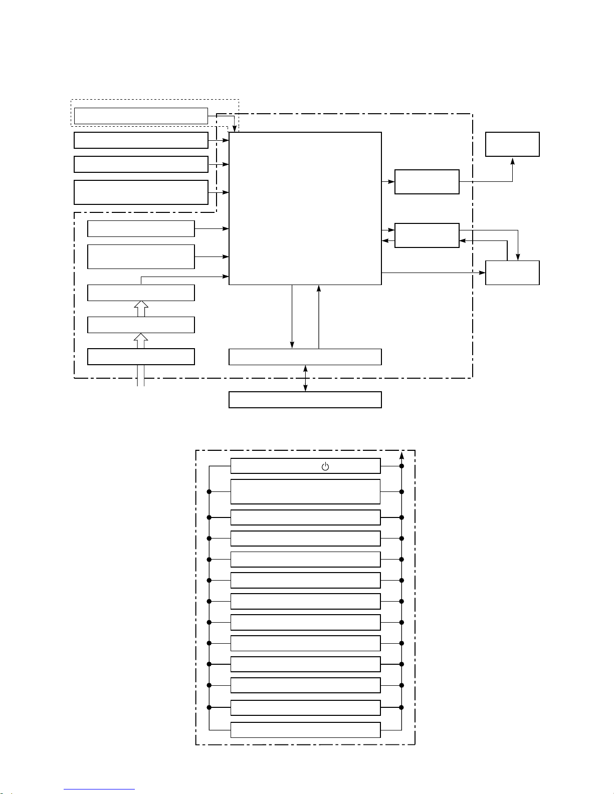
REMOTE CONTROLLER
QUIET
Remote Controller
Infrared Rays, 36.7kHz
Hi-POWER
SLEEP (1, 3, 5, 9 OFF TIMER)
COMFORT SLEEP
ECO
Louver Direction Setting
Louver AUTO Swing
OFF TIMER Setting
ON TIMER Setting
Fan Speed Selection
Thermo. Setting
Operation Mode Selection
AUTO, COOL, DRY, HEAT, FAN
Functions
• Cold draft preventing Function
• 3-minute Delay at Restart
for Compressor
• Fan Motor Starting Control
• Processing
(Temperature Processing)
• Timer
• Serial Signal Communication
• Clean Function
Heat Exchanger Sensor (TC)
Room Temperature Sensor (TA)
Infrared Rays Signal Receiver
and Indication
Initializing Circuit
Power Supply Circuit
Converter (D.C circuit)
Noise Filter
Clock Frequency
Oscillator Circuit
M.C.U.
Power Supply
(From Outdoor Unit)
Serial Signal Transmitter/Receiver
Serial Signal Communication
(Operation Command and Information)
Indoor Unit Control Unit
Louver Motor
Drive Control
Indoor Fan
Motor Control
Indoor
Fan Motor
Louver
Motor
QUIET
Operation ( )
8. CONTROL BLOCK DIAGRAM
FILE NO. SVM-12056
8-1. Indoor Unit
Heat Exchanger Sensor (TCJ)
(For RAS-B22N3KV2-E only)
– 23 –
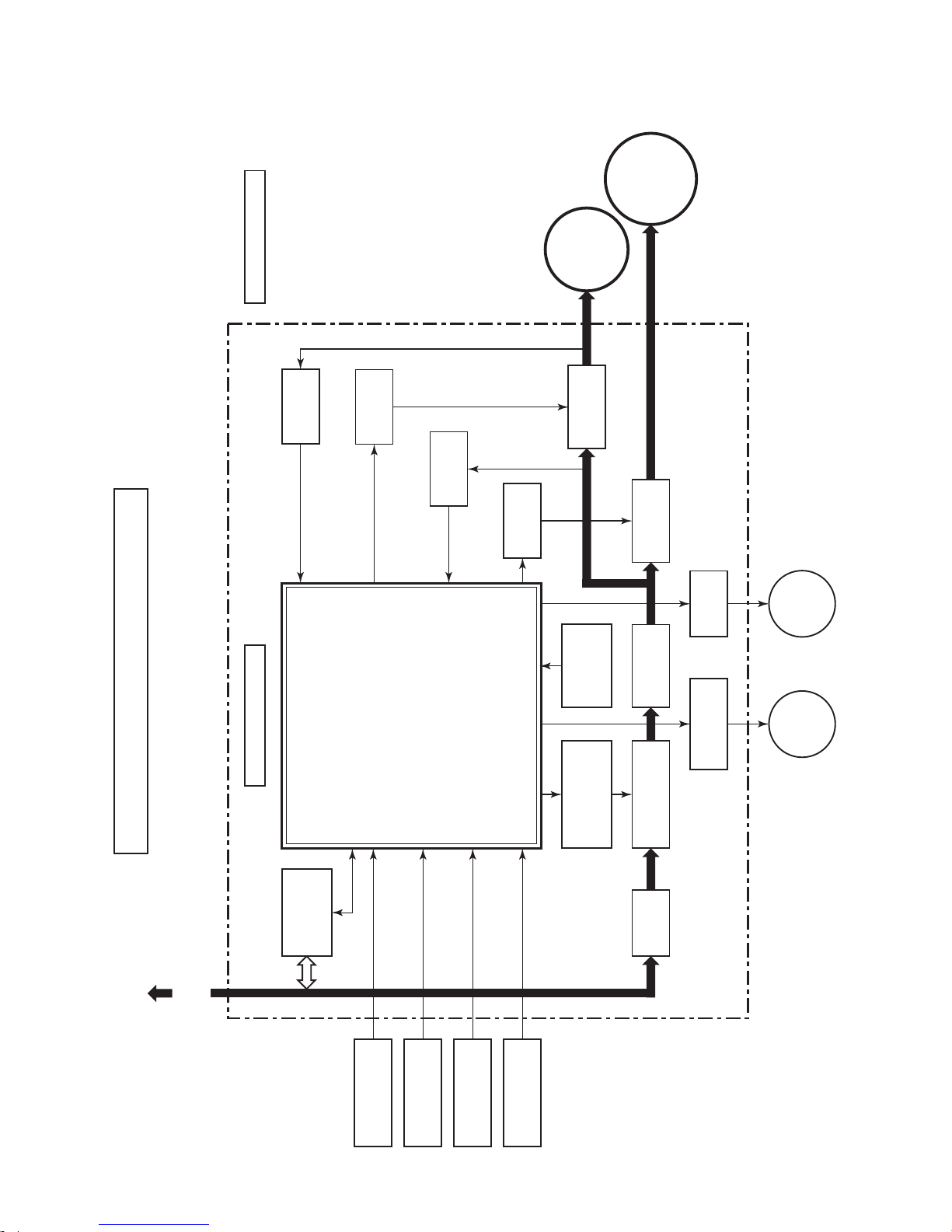
8-2. Outdoor Unit (Inverter Assembly)
FILE NO. SVM-12056
Driver circuit
of PMV
Relay
circuit
Clock
frequency
4MHz
Converter
(AC → DC)
Inverter
(DC → AC)
Inverter
(DC → AC)
Input current
sensor
High Power
factor Correction
circuit
CONTROL BLOCK DIAGRAM
For INDOOR UNIT
Heat exchanger
temp.sensor
Suction
temp. sensor
Outdoor air
temp. sensor
Discharge
temp. sensor
Indoor unit
send/receive
circuit
Noise
Filter
MCC5009 (PCB)
• PWM synthesis function
• Input current release control
• IGBT over-current detect control
• Outdoor fan control
• High power factor correction control
• Inverter output frequency control
• A/D converter function
• PMV control
• Discharge temp. control
• 4-way valve control
• Signal communication to indoor unit
PMV : Pulse Motor Valve
MCU : Micro Controller Unit
Outdoor
Fan motor
Compressor
OUTDOOR UNIT
PMV
4-way
valve
Gate drive
circuit
Current
detect
Current
detect
Gate drive
circuit
M.C.U.
Power Supply
220-240V ~50Hz, 220-230V ~60Hz
– 24 –

9. OPERATION DESCRIPTION
9-1. Outline of Air Conditioner Control
This air conditioner is a capacity-variable type air
conditioner, which uses DC motor for the indoor fan
motor and the outdoor fan motor. And the capacityproportional control compressor which can change the
motor speed in the range from 11 to 120 rps is
mounted. The DC motor drive circuit is mounted to the
indoor unit. The compressor and the inverter to control
fan motor are mounted to the outdoor unit.
The entire air conditioner is mainly controlled by the
indoor unit controller.
The indoor unit controller drives the indoor fan motor
based upon command sent from the remote controller,
and transfers the operation command to the outdoor
unit controller.
The outdoor unit controller receives operation command from the indoor unit side, and controls the
outdoor fan and the pulse motor valve. (PMV)
Besides, detecting revolution position of the compressor motor, the outdoor unit controller controls speed of
the compressor motor by controlling output voltage of
the inverter and switching timing of the supply power
(current transfer timing) so that motors drive according
to the operation command.
And then, the outdoor unit controller transfers reversely
the operating status information of the outdoor unit to
control the indoor unit controller.
As the compressor adopts four-pole brushless
DC motor, the frequency of the supply power
from inverter to compressor is two-times cycles
of the actual number of revolution.
1. Role of indoor unit controller
The indoor unit controller judges the operation
commands from the remote controller and assumes
the following functions.
• Judgment of suction air temperature of the indoor
heat exchanger by using the indoor temp. sensor.
(TA sensor)
• Judgment of the indoor heat exchanger temperature by using heat exchanger sensor (TC sensor)
(Prevent-freezing control, etc.)
• Louver motor control
• Indoor fan motor operation control
• LED (Light Emitting Diode) display control
• Transferring of operation command signal
(Serial signal) to the outdoor unit
• Reception of information of operation status
(Serial signal including outside temp. data) to the
outdoor unit and judgment/display of error
2. Role of outdoor unit controller
Receiving the operation command signal
(Serial signal) from the indoor unit controller, the
outdoor unit performs its role.
• Compressor operation control
• Operation control of outdoor fan motor
• PMV control
• 4-way valve control
• Detection of inverter input current and current
release operation
• Over-current detection and prevention operation
to IGBT module (Compressor stop function)
• Compressor and outdoor fan stop function when
serial signal is off (when the serial signal does not
reach the board assembly of outdoor control by
trouble of the signal system)
• Transferring of operation information (Serial
signal) from outdoor unit controller to indoor unit
controller
• Detection of outdoor temperature and operation
revolution control
• Defrost control in heating operation (Temperature
measurement by outdoor heat exchanger and
control for 4-way valve and outdoor fan)
3. Contents of operation command signal
(Serial signal) from indoor unit controller to
outdoor unit controller
The following three types of signals are sent from
the indoor unit controller.
• Operation mode set on the remote controller
• Compressor revolution command signal defined
by indoor temperature and set temperature
(Correction along with variation of room temperature and correction of indoor heat exchanger
temperature are added.)
• Temperature of indoor heat exchanger
• For these signals ([Operation mode] and [Com-
pressor revolution] indoor heat exchanger temperature), the outdoor unit controller monitors the
input current to the inverter, and performs the
followed operation within the range that current
does not exceed the allowable value.
4. Contents of operation command signal
(Serial signal) from outdoor unit controller
to indoor unit controller
The following signals are sent from the outdoor unit
controller.
• The current operation mode
• The current compressor revolution
• Outdoor temperature
• Existence of protective circuit operation
For transferring of these signals, the indoor unit
controller monitors the contents of signals, and
judges existence of trouble occurrence.
Contents of judgment are described below.
• Whether distinction of the current operation
status meets to the operation command signal
• Whether protective circuit operates
When no signal is received from the outdoor
unit controller, it is assumed as a trouble.
Operations followed to judgment
of serial signal from indoor side.
FILE NO. SVM-12056
– 25 –

9-2. Operation Description
1. Basic operation ........................................................................................................... 27
1. Operation control ................................................................................................... 27
2. Cooling/Heating operation ..................................................................................... 28
3. AUTO operation...................................................................................................... 28
4. DRY operation ........................................................................................................ 28
2. Indoor fan motor control.............................................................................................. 29
3. Outdoor fan motor control ........................................................................................... 30
4. Capacity control .......................................................................................................... 32
5. Current release control ............................................................................................... 32
6. Release protective control by temperature of indoor heat exchanger ........................ 33
7. Defrost control (Only in heating operation)................................................................. 34
8. Louver control ............................................................................................................. 35
1) Louver position....................................................................................................... 35
2) Air direction adjustment ......................................................................................... 35
3) Swing ..................................................................................................................... 35
9. ECO operation ............................................................................................................ 36
10. Temporary operation................................................................................................... 37
11. Discharge temperature control .................................................................................. 37
FILE NO. SVM-12056
12. Pulse motor valve (PMV) control ................................................................................ 38
13. Self-Cleaning function ................................................................................................ 39
14. Remote Controller-A or B selection ............................................................................ 40
15. QUIET mode ............................................................................................................... 41
16. COMFORT SLEEP ..................................................................................................... 41
17. Short Timer ................................................................................................................. 41
18. One Touch Comfort ..................................................................................................... 42
19. Hi POWER Mode ........................................................................................................ 42
20. FILTER Indicator ......................................................................................................... 42
9-3. Auto Restart Function
9-3-1. How to Set the Auto Restart Function ........................................................................ 43
9-3-2. How to Cancel the Auto Restart Function.................................................................. 44
9-3-3. Power Failure during Timer Operation........................................................................ 44
9-4. Remote Controller
9-4-1. Remote Controller and Its Functions ........................................................................... 45
9-4-2. Operation of Remote Controller ................................................................................... 45
9-4-3. Names and Functions of Indications on Remote Controller ........................................ 48
– 26 –
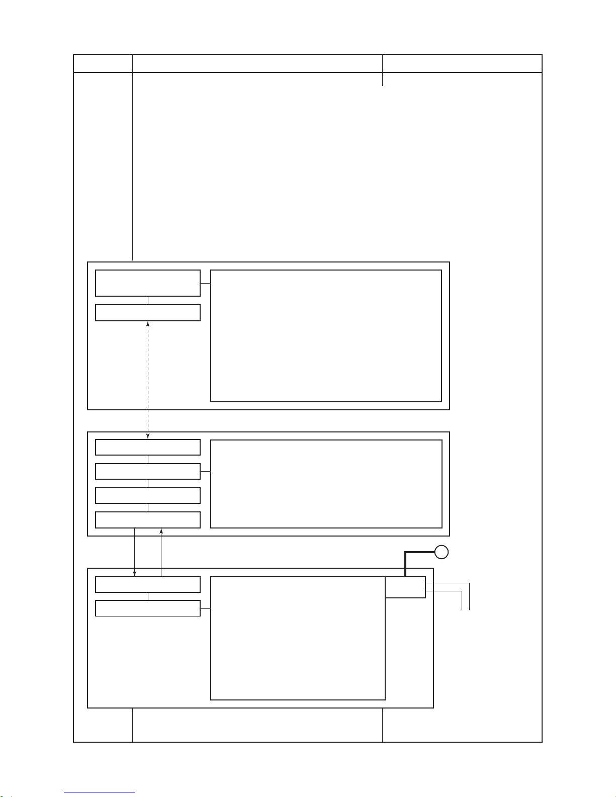
Item
1. Basic
operation
Operation flow and applicable data, etc.
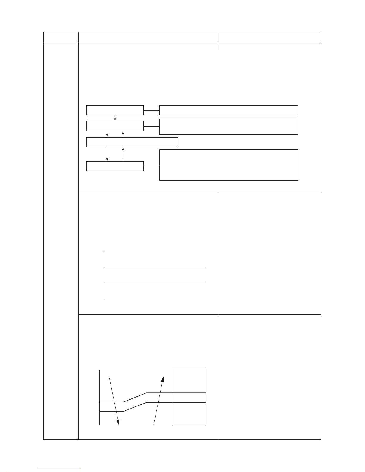
1. Operation control
Receiving the user’s operation condition setup, the operation statuses of indoor/outdoor units are
controlled.
1) The operation conditions are selected by the remote controller as shown in the below.
2) A signal is sent by ON button of the remote controller.
3) The signal is received by a sensor of the indoor unit and processed by the indoor controllers as
shown in the below.
4) The indoor controller controls the indoor fan motor and louver motor.
5) The indoor controller sends the operation command to the outdoor controller, and sends/
receives the control status with a serial signal.
6) The outdoor controller controls the operation as shown in the left, and also controls the compressor, outdoor fan motor, 4-way valve and pulse motor valve.
Description
Control contents of remote controller
• ON/OFF (Air conditioner)
• Operation select (COOL /HEAT / AUTO / DRY)
• Temperature setup
• Air direction
• Swing
• Air volume select
(AUTO / LOW / LOW+ / MED / MED+ / HIGH)
• ECO • COMFORT SLEEP
• ON timer setup • QUIET
• OFF timer setup • PRESET
• Hi-POWER • ONE-TOUCH
Indoor unit control
• Command signal generating function of
indoor unit operation
• Calculation function (temperature calculation)
• Activation compensation function of indoor fan
• Cold draft preventive function
• Timer function
• Indoor heat exchanger release control
• Indoor fan motor
• Louver motor
Outdoor unit control
• Frequency control of inverter output
• Waveform composite function
• Calculation function
(Temperature calculation)
• AD conversion function
• Quick heating function
• Delay function of compressor reactivation
• Current release function
• GTr over-current preventive function
• Defrost operation function
• Compressor
• Outdoor fan motor
• 4-way valve
• Pulse Motor valve
(PMV)
~
Remote controller
Indoor unit
Outdoor unit
Serial signal send/receive
Outdoor unit control
Inverter
Indoor unit control
Operation command
Serial signal send/receive
Signal receiving
Selection of
operation conditions
ON/OFF
FILE NO. SVM-12056
– 27 –
Ts + 1
Ts – 1
Ta
Cooling operation
Monitoring (Fan)
Heating operation
Tsc
+
0.5
+
1.0
[C]
Ta
Fan speed
L (W5)
(W5+W3) / 2
SL (W3)
Item
1. Basic
operation
Operation flow and applicable data, etc.
2. Cooling/Heating operation
The operations are performed in the following parts by controls according to cooling/heating conditions.
1) Receiving the operation ON signal of the remote controller, the cooling or heating operation signal
starts being transferred form the indoor controller to the outdoor unit.
2) At the indoor unit side, the indoor fan is operated according to the contents of “2. Indoor fan motor
control” and the louver according to the contents of “8. Louver control”, respectively.
3) The outdoor unit controls the outdoor fan motor, compressor, pulse motor valve and
4-way valve according to the operation signal sent from the indoor unit.
3. AUTO operation
Selection of operation mode
As shown in the following figure, the operation starts by
selecting automatically the status of room temperature
(Ta) when starting AUTO operation.
*1. When reselecting the operation mode, the fan speed
is controlled by the previous operation mode.
4. DRY operation
DRY operation is performed according to the difference
between room temperature and the setup temperature
as shown below.
In DRY operation, fan speed is controlled in order to
prevent lowering of the room temperature and to avoid
air flow from blowing directly to persons.
Description
1) Detects the room temperature (Ta) when
the operation started.
2) Selects an operation mode from Ta in
the left figure.
3) Fan operation continues until an
operation mode is selected.
4) When AUTO operation has started
within 2 hours after heating operation
stopped and if the room temperature is
20°C or more, the fan operation is
performed with ”Super Ultra LOW” mode
for 3 minutes.
Then, select an operation mode.
5) If the status of compressor-OFF
continues for 15 minutes the room
temperature after selecting an operation
mode (COOL/HEAT), reselect an
operation mode.
1) Detects the room temperature (Ta) when
the DRY operation started.
2) Starts operation under conditions in the
left figure according to the temperature
difference between the room temperature and the setup temperature (Tsc).
Setup temperature (Tsc)
= Set temperature on remote controller
(Ts) + (0.0 to 1.0)
3) When the room temperature is lower
1°C or less than the setup temperature,
turn off the compressor.
Setup of remote controller
Indoor fan motor control / Louver control / Operation Hz
Control (Requierment)
[ ]
Compressor revolution control / Outdoor fan motor control /
Operation Hz control (Include limit control)
4-way valve control In cooling operation: ON
In heating operation: OFF
Pulse Motor valve control
Outdoor unit control
Sending of operation command signal
Indoor unit control
Operation ON
FILE NO. SVM-12056
– 28 –
+2.5
Ta
[°C]
+2.0
+1.5
+1.0
+0.5
Ts c
a
b
c
d
e
M+(WB)
*3
*4
*5
L(W6)
Air volume AUTO
L
L+
M
M+
H
W6
(L + M) / 2
W9
(M + H) / 2
WC
Indication
Fan speed
Fan speed setup
COOL ON
AUTO
MANUAL
*3 : Fan speed = [(M +) –L] x 3/4 + L
*4 : Fan speed = [(M +) –L] x 2/4 + L
*5 : Fan speed = [(M +) –L] x 1/4 + L
(Linear approximation
from M+ and L)
Item
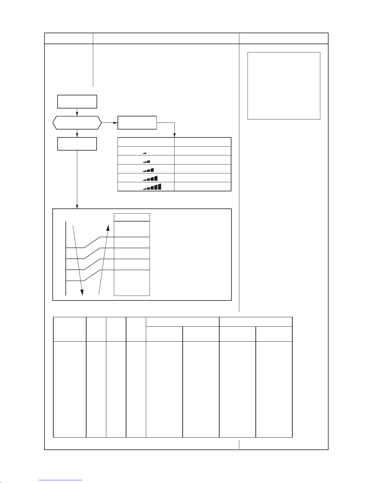
2. Indoor fan
motor control
Operation flow and applicable data, etc.
<In cooling operation>
(This operation controls the fan speed at indoor unit side.)
The indoor fan (cross flow fan) is operated by the phase-
control induction motor. The fan rotates in 5 stages in
MANUAL mode, and in 5 stages in AUTO mode, respectively.
(Table 1)
(Fig. 2)
Description
∗∗
∗
* The fan speed broadly varies due
to position of the louver, etc.
The described value indicates one
under condition of inclining
downward blowing.
1) When setting the fan speed to L,
L+, M, M+ or H on the remote
controller, the operation is
performed with the constant
speed shown in Fig. 1.
2) When setting the fan speed to
AUTO on the remote controller,
revolution of the fan motor is
controlled to the fan speed level
shown in Fig. 2 and Table 1
according to the setup temperature, room temperature, and heat
exchanger temperature.
(Fig. 1)
FILE NO. SVM-12056
(Table 1) Indoor fan air flow rate
∗∗
∗∗
∗ Symbols
UH: Ultra High
H : High
M+: Medium+
M : Medium
L+ : Low+
L- : Low–
UL : Ultra Low
SUL
: Super Ultra Low
L : Low
Fan speed Air flow rate Fan speed Air flow rate
(rpm) (m3/h) (rpm) (m3/h)
WF UH 1100 990 1200 1100
WE H 1100 990 1200 1100
WD M+ 1090 980 1200 1100
WC H 1070 957 1180 1080
WB M+ M 980 858 1080 968
WA 940 813 1020 900
W9 M L+ 890 758 980 858
W8 L 780 636 850 713
W7 L+ L- L+ 750 603 810 670
W6 L L 740 590 800 658
W5 L- UL L- 700 547 760 614
W4 UL UL 700 547 700 547
W3 SUL SUL 650 492 650 492
W2 SUL 500 325 500 325
W1 500 325 500 325
RAS-18N3KV2-E RAS-B22N3KV2-E
Fan speed
level
COOL HEAT DRY
– 29 –
 Loading...