

Toshiba RAS-24UFHP-E5, RAS-24NAH-E, RAS-24NA-E, RAS-18UFP-E5, RAS-B18UFPX5 Service Manual
...
FILE NO. SVM-06006
SERVICE MANUAL
AIR-CONDITIONER
UNDER CEILING / CONSOLE TYPE
RAS-18UFHP-E5 / RAS-18NAH-E
RAS-24UFHP-E5 / RAS-24NAH-E
RAS-18UFP-E5 / RAS-18NA-E
RAS-24UFP-E5 / RAS-24NA-E
RAS-B18UFPX5 / RAS-18N2AX
RAS-24UFPX5 / RAS-24N2AX
18 Class 24 Class
May, 2006

CONTENTS
1. SPECIFICATIONS
1-1 18 Class
1-2 24 Class
2. CONSTRUCTION VIEWS
2-1 Indoor Unit
2-2 Outdoor Unit (24 Class)
2-3 Outdoor Unit (18 Class)
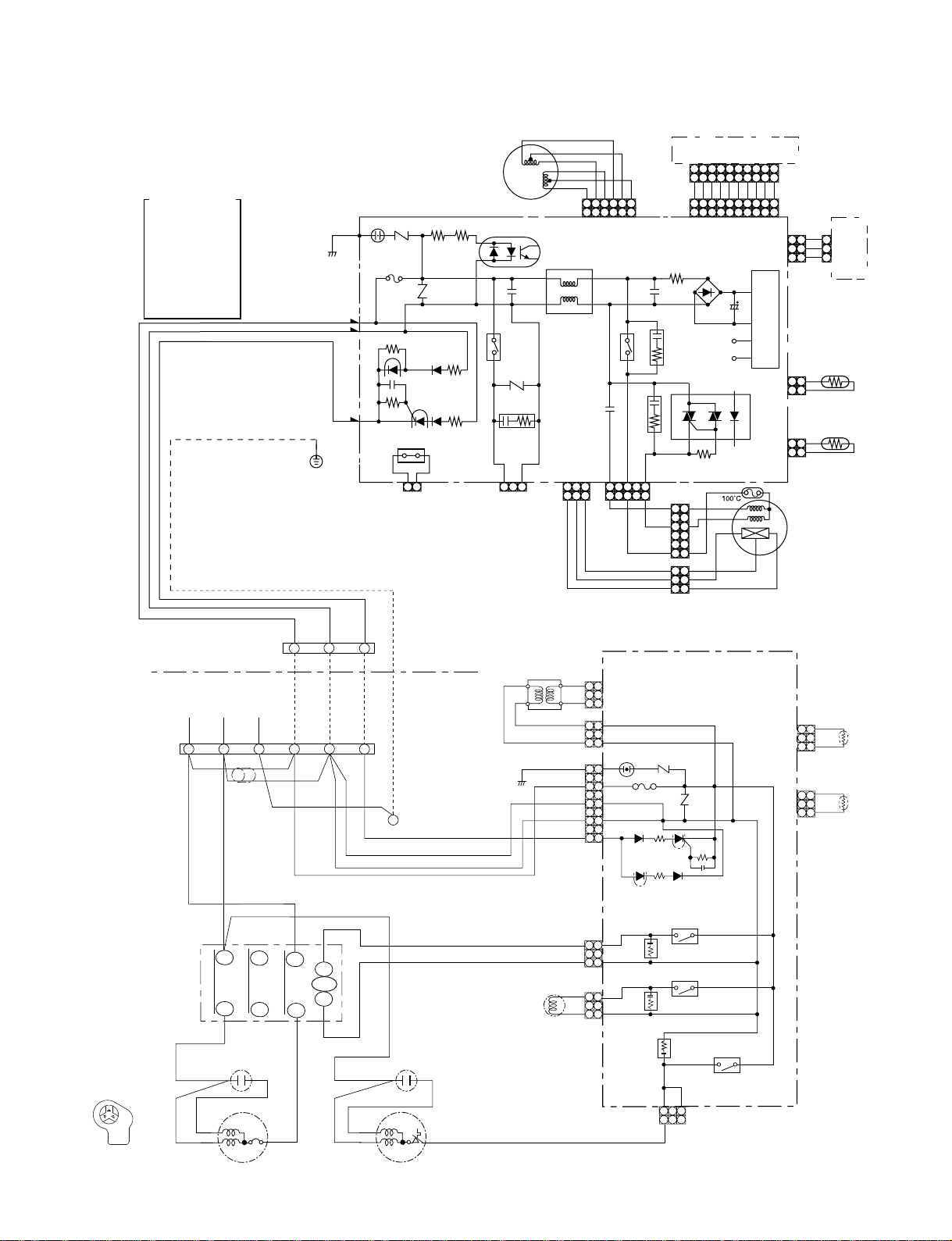
3. WIRING DIAGRAM
3-1 RAS-18UFHP-E5 / RAS-18NAH-E
3-2 RAS-18UFP-E5 / RAS-18NA-E, RAS-B18UFPX5 / RAS-18N2AX
3-3 RAS-24UFHP-E5 / RAS-24NAH-E
RAS-24UFP-E5 / RAS-24NA-E
3-4
RAS-24UFPX5 / RAS-24N2AX
4. SPECIFICATION OF ELECTRICAL PARTS
4-1 Indoor Unit
4-2 Outdoor Unit (RAS-18N2AH-E)
4-3 Outdoor Unit (RAS-18N2AX, RAS-18NA-E)
4-4 Outdoor Unit (RAS-24N2AH-E)
4-5 Outdoor Unit (RAS-24NA-E, RAS-24N2AX4)
FILE NO. SVM-06006
5. REFRIGERATION CYCLE DIAGRAM
5-1 RAS-18UFHP-E5 / RAS-18NAH-E
5-2 RAS-18UFP-E5 / RAS-18UA-E
RAS-B18UFPX5 / RAS-18N2AX
RAS-24UFHP-E5 / RAS-24NAH-E
5-3
RAS-24UFP-E5 / RAS-24NA-E
5-4
RAS-24UFPX5 / RAS -24N2AX
6. CONTROL BLOCK DIAGRAM
6-1 RAS-18UFHP-E5, RAS-24UFHP-E5
6-2 RAS-18UFP-E5, RAS-B18UFPX5
RAS-24UFP-E5, RAS-24UFPX5
− 1 −

7. OPERATION DESCRIPTION
7-1 Outline of Air Conditioner Control
7-2 Description of Operation Circuit
7-3 Hi POWER Mode
7-4 High-Temperature Limit Control
7-5 Low-Temperature Limit Control
7-6 Defrosting Operation
7-7 Auto Restart Function
7-8 Filter Check Lamp
7-9 Self-Cleaning function
7-10 QUIET Mode
7-11 COMFORT SLEEP mode
8. INSTALLATION PROCEDURE
8-1 Safety Cautions
8-2 Installation Diagram of Indoor and Outdoor Units
8-3 Installation
8-4 Indoor Unit
8-5 Outdoor unit
8-6 How to Set Remote Control Selector Switch
8-7 How to Use Drain Pump Kit of Option
8-8 Others
FILE NO. SVM-06006
9. TROUBLESHOOTING CHART
9-1 Troubleshooting Procedure
9-2 Basic Check Items
9-3 Primary Judgement
9-4 Self-Diagnosis by Remote Control (Check Code)
9-5 How to Diagnose Faulty Parts
9-6 Troubleshooting for Indoor Unit
9-7 Troubleshooting for Wiring (Interconnect Cable and Serial Signal Wire)
9-8 Troubleshooting for P.C. Board
9-9 Troubleshooting for Remote Control
10. PARTS REPLACEMENT
10-1 Indoor Unit
10-2 Outdoor Unit (RAS-24NAH-E, RAS-24NA-E, RAS-24N2AX)
10-3
Outdoor Unit (RAS-18NAH-E)
10-4
Outdoor Unit (RAS-18NA-E4, RAS-18N2AX)
11.3 EXPLODED
11-1 Indoor Unit (E-Parts Assy)
11-2 Indoor Unit
11-
Outdoor Unit
11-4 Outdoor Unit (RAS-18NA-E, RAS-18N2AX)
11-5 Outdoor Unit (RAS-24NAH-E)
11-6 Outdoor Unit (RAS-24NA-E, RAS-24N2AX)
VIEWS AND P AR
(RAS-18
NAH-E)
TS LIST
− 2 −
FILE NO. SVM-06006
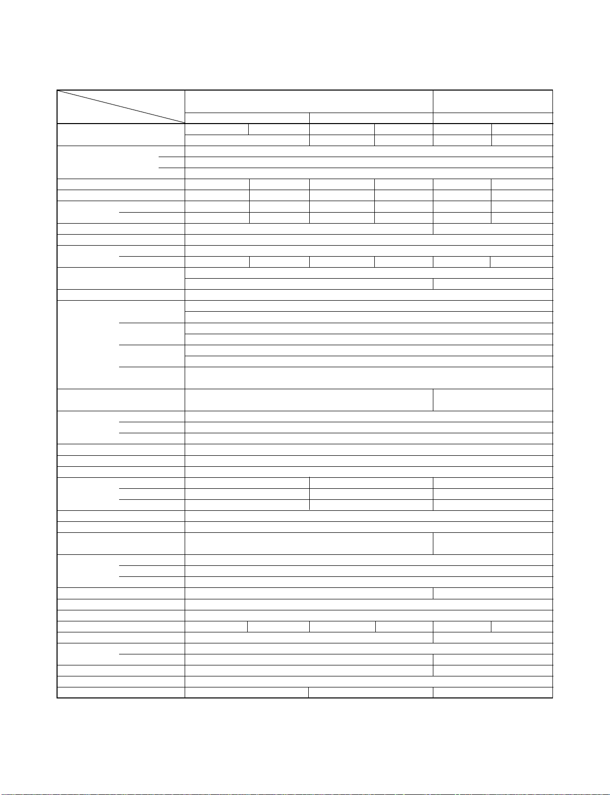
1. SPECIFICATIONS
1-1
ITEM
Capacity kW 220V 240V 220V 240V 220V 240V
Power source V 220 – 240
Power consumption W 2000 2130 1830 2000 2000 2120
Power factor % 95 87 93 84 96 91
Running current
Starting current A
Moisture removal lit/h 2.0
Noise
Refrigerant
Refrigerant control Capillary tube
Interconnection Connection type Flare connection
pipe Maximum length m 15*
INDOOR UNIT RAS-18UFHP-E5
Dimensions Height mm 633
Net weight kg 23
Evaporator type Finned tube
Indoor fan type Multi blade fan
Air volume Medium fan m3/h 680 700 680
Fan motor output W 50
Air filter Washable -filter
OUTDOOR UNIT
Dimensions Height mm
Net weight kg 43 41
Condenser type Finned tube
Outdoor fan type Propeller fan
Airflow volume m3/h 2350 2450 2350 2450 2350 2450
Fan motor output W 65 42
Compressor
Safety device IOL, Td Sensor IOL
Louver type Automatic louver
Usable outdoor temperature range °C 15 ~ 43 –10 ~ 24 21 ~ 43
Note *1 Chargeless pipe
*2 Maximum pipe
Indoor A 0.40 0.40 0.40 0.40 0.40 0.40
Outdoor A 9.20 9.85 8.50 9.50 9.05 9.30
Indoor (H/M/L) dB 43/41/39/37/36
Outdoor dB 52 53 53 54 51 52
Name of refrigerant R-22
Rated amount kg 1.53 1.0
Gas side size mm ∅12.70
Connection type Flare connection
Liquid side size mm ∅6.35
(One way) 20*
Maximum height m
difference
Width mm 1093
Depth mm 208
High fan m3/h 800 830 800
Low fan m3/h 580 650 580
Width mm
Depth mm
Model PH340X3C-4KT1
Output W
MODEL
Cooling Heating Cooling
5.00 5.70 5.80 5.20 5.25
Phase 1∅
Hz 50
RAS-18UFHP-E5/18NAH-E
45
1
2
8
RAS-18UFP-E5
RAS-18NAH-E
780
550
290
1500
42
RAS-18UFP-E5/18NA-E
RAS-B18UFPX5/18N2AX
RAS-B18UFPX5
RAS-18NA-E
RAS-18N2AX
1500
– 3 –
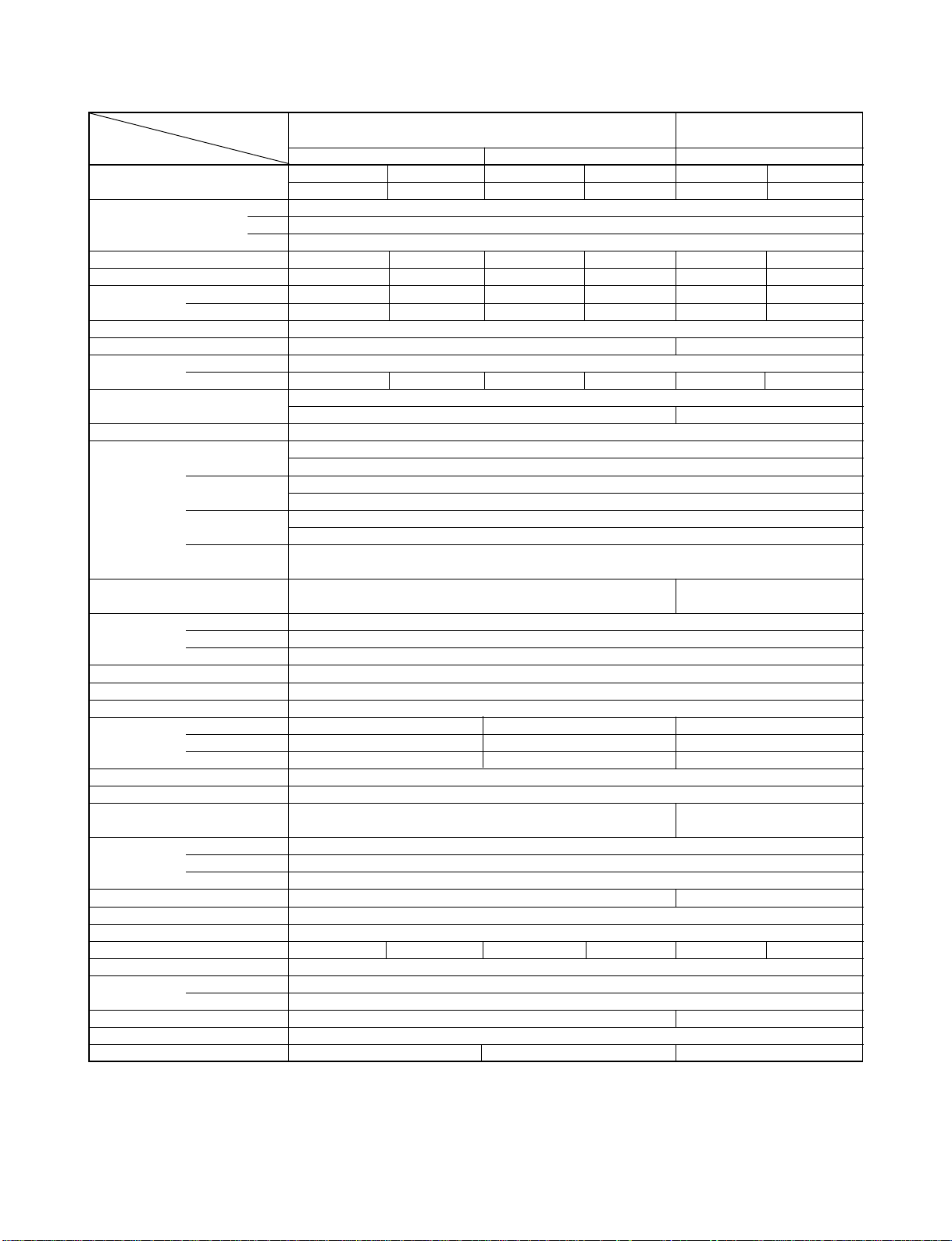
1-2
FILE NO. SVM-06006
ITEM
Capacity kW 220V 240V 220V 240V 220V 240V
Power source V 220 – 240
Power consumption W 2480 2650 2410 2590 2260 2400
Power factor % 97 89 94 86 92 84
Running current
Starting current A
Moisture removal lit/h
Noise
Refrigerant
Refrigerant control Capillary tube
Interconnection Connection type Flare connection
pipe Maximum length m 15*
INDOOR UNIT RAS-24UFHP-E5
Dimensions Height mm 633
Net weight kg 23
Evaporator type Finned tube
Indoor fan type Multi blade fan
Air volume Medium fan m3/h 750 760 750
Fan motor output W 50
Air filter Washable -filter
OUTDOOR UNIT
Dimensions Height mm
Net weight kg 56 52
Condenser type Finned tube
Outdoor fan type Propeller fan
Airflow volume m3/h 2400 2550 2400 2550 2400 2550
Fan motor output W
Compressor
Safety device IOL, Td Sensor IOL
Louver type Automatic louver
Usable outdoor temperature range °C 15 ~ 43 –10 ~ 24 21 ~ 43
Note *1 Chargeless pipe
*2 Maximum pipe
Indoor A 0.45 0.45 0.45 0.45 0.45 0.45
Outdoor A 11.15 11.95 11.20 12.05 10.75 11.40
Indoor (H/M/L) dB 46/44/42/39/37
Outdoor dB 56 57 57 58 56 57
Name of refrigerant R-22
Rated amount kg 2.00 1.68
Gas side size mm ∅15.88
Connection type Flare connection
Liquid side size mm ∅6.35
(One way) 25*
Maximum height m
difference
Width mm 1093
Depth mm 208
High fan m3/h 900 930 900
Low fan m3/h 650 660 650
Width mm
Depth mm
Model PH400X3CS-4KT1
Output W
MODEL
Cooling Heating Cooling
6.10 6.20 6.60 6.70 6.10 6.20
Phase 1∅
Hz 50
RAS-24UFHP-E5/24NAH-E
67
2.5
1
2
10
RAS-24UFP-E5
RAS-24NAH-E
780
715
290
42
1800
2.7
RAS-24UFP-E5/24NA-E
RAS-24UFPX5/24N2AX
RAS-24UFPX5
RAS-24NA-E
RAS-24N2AX
– 4 –
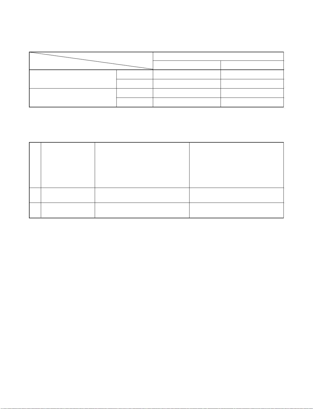
Note : 1
• Capacity is based on the following temperature conditions.
FILE NO. SVM-06006
Condition
Temperature
Indoor unit inlet air temperature
Outdoor unit inlet air temperature
(DB) 27°C 20°C
(WB) 19°C 15°C
(DB) 35°C 7°C
(WB) 24°C 6°C
Note : 2
• Charge refrigerant according to the table below.
RAS-18UFHP-E5 / RAS-18NAH-E RAS-24UFHP-E5 / RAS-24NAH-E
Refrigerant
*1 No need to charge
refrigerant
*2 Need to charge
refrigerant
RAS-18UFP-E5 / RAS-18NA-E RAS-24UFP-E5 / RAS-24NA-E
RAS-B18UFPX5 / RAS-18N2AX RAS-24UFPX5 / RAS-24N2AX
15m or less 15m or less
Over 15m up to 20m (20g/m) Over 15m up to 25m (30g/m)
JIS B8615-1
Cooling Heating
– 5 –
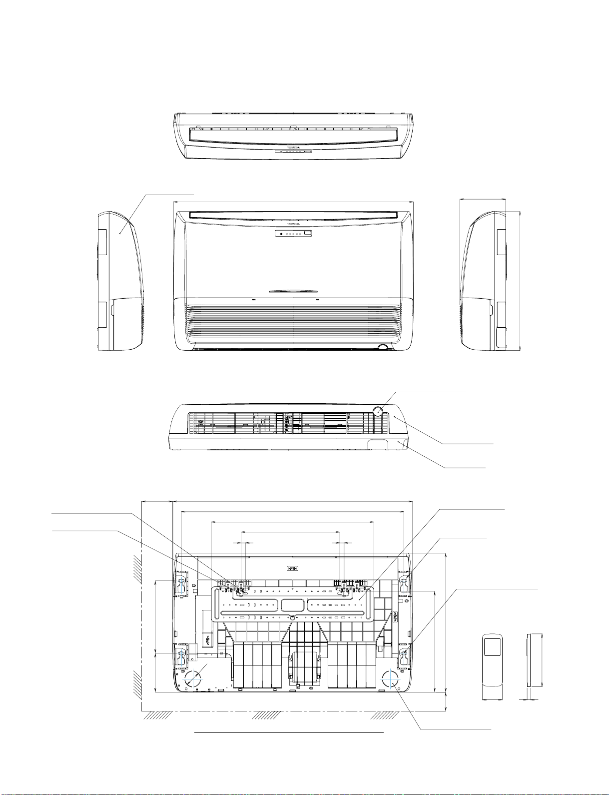
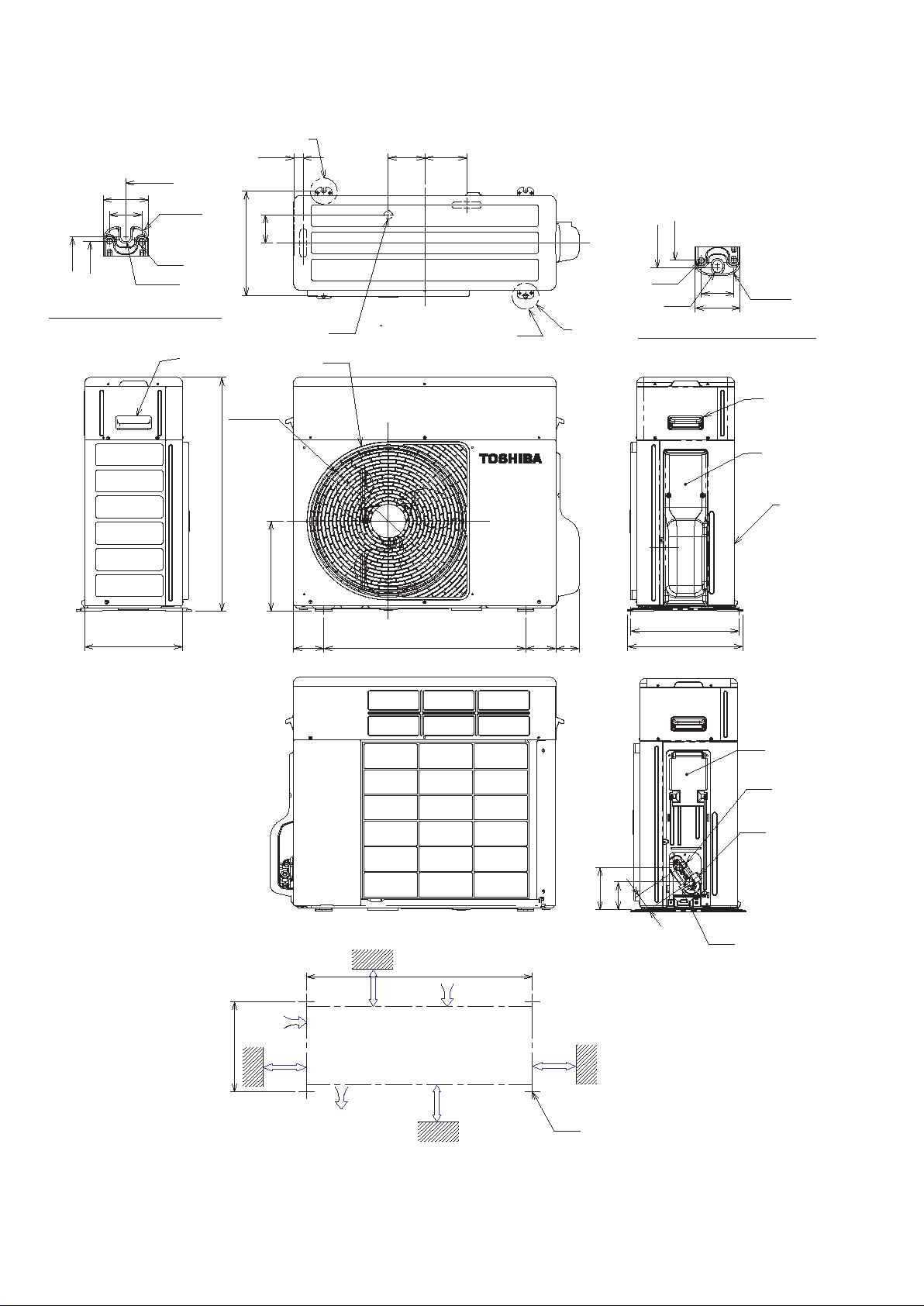
2-1. Indoor Unit
FILE NO. SVM-06006
2. CONSTRUCTION VIEWS
Front panel
1093
208
633
Knock out system
Grille air inlet
Back Body
For stud bolt
(∅8 - ∅10)
For stud bolt (∅6)
200 Min
330165
1093
1015
742
450
20 20
∅74
UNDER CEILING & CONSOLE INSTALLATION
– 6 –
Installation plate
Mount plate
M10 Suspention bolt
633
460
70 Min
Wireless remote control
Knock out system
160
57 18
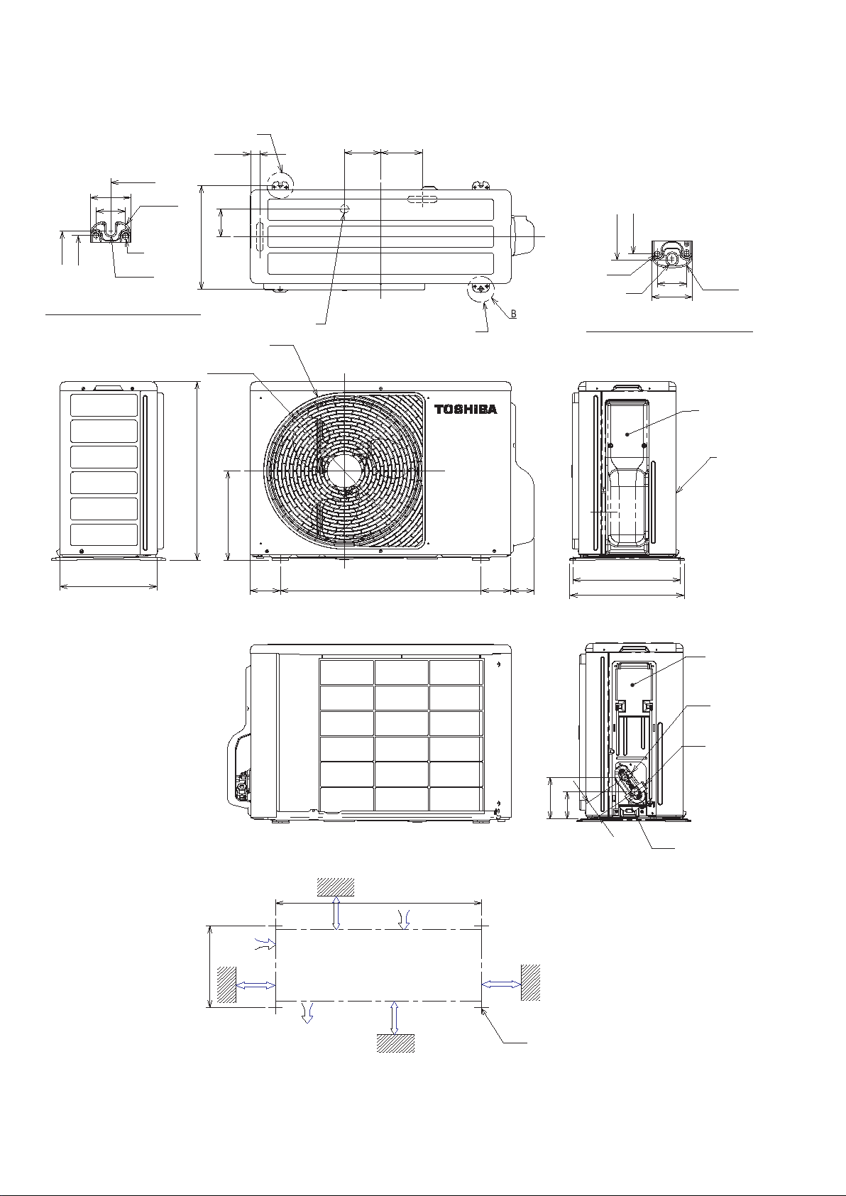
2-2. Outdoor Unit (24 Class)
A
28
600
50
36
R
15
FILE NO. SVM-06006
124109
6 hole
321
307
Ø
R
5.5
A Detail Drawing (Back leg)
HANDLE
290
321
Ø
Ø
715
86
25 Drain outlet
FAN-GUARD
436
275
90 600 90 69
2Ø11x14 Hole
(For
Ø8-Ø
10 anchor bolt)
B
307
321
Hole
6
Ø
11x14 Hole
Ø
36
50
B Detail Drawing (Front leg)
321
342
R
15
HANDLE
COVER-PV
Z
100 or more
321
100 or more
Z View
600
Air inlet
Air out
let
00 or more
6
Installation dimension
600 or more
4x
54
129
84
11 Long holes(For
Ø
Service port
10 anchor bolt)
Ø8-Ø
Electrical part cover
Liquid side
(Flare Ø6.35)
Gas-side
(Flare Ø15.88)
− 7 −
2-3. Outdoor Unit (18 Class)
A
28
600
50
36
321
307
A detail Drawing (Back leg)
R5.5
R
Ø
15
6 hole
86
321
Ø
25 Drain outlet
FAN-GUARD
436
Ø
109 124
2
-
Ø
11 x 14
(For 8 -
Ø
Ø
Hole
10 anchor bolt)
FILE NO. SVM-06006
307
321
Ø
6 hole
11x14 hole
Ø
B Detail Drawing (Front leg)
36
50
R
15
COVER-PV
Z
290
550
275
321
342
Electrical part cover
Liquid side
(Flare 6.35)
Ø
Gas side
(Flare 12.7)
Ø
5
4
Service port
Z View
9060090
69
129
84
100 or more
321
100 or more
600
Air intlel
Air outlel
600 or more
Installation dimension
− 8 −
600 or more
4x 11 Long holes(For 8- 10 anchor bolt)
Ø
Ø
Ø
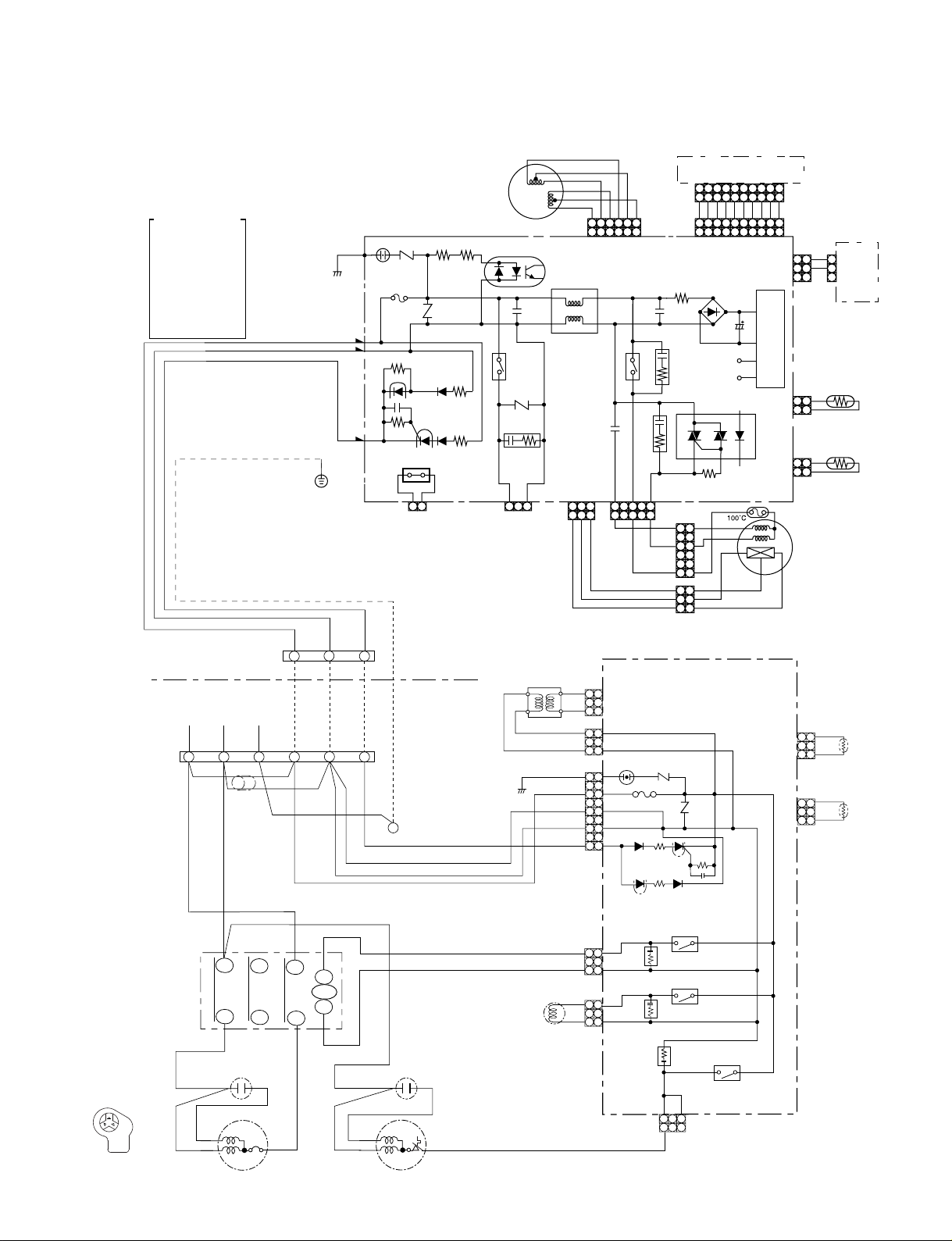
3. WIRING DIAGRAM
3-1. RAS-18UFHP-E5 / RAS-18NAH-E
FILE NO. SVM-06006
COLOR IDENTIFICATION
BRW : BROWN
RED : RED
WHI : WHITE
YEL : YELLOW
BLU : BLUE
BLK : BLACK
GRY : GRAY
PNK : PINK
ORN : ORANGE
GRN&YEL : GREEN&
GRN : GREEN
PUR : PURPLE
YELLOW
BLK
WHI
RED
GRN&YEL
BLK
CN30
CN31
CN23
P04
SG01
R22
FUSE
F01
250VAC
T6.3A
J401
2
1 1 1232 3
FOR FLOAT SWITCH
(OPTION)
When you use float
switch you should
cut J401
LOUVER
MOTOR
R09 R507
R21
CN402 CN401 CN11
IC04
C15
RY401
R405
CR401
FOR DRAIN PUMP
(OPTION)
CN07
L01
ORN
RED
PNK
YEL
BRW
BLU
123
654
654
C501
321
321
MAIN PCB
MCC-865A
RY501
5 3
5 311
BRW
GRY
YEL
CN25
CN13
R01
C01
CR502
CR501
CN10 BLK
WHI
1 1
RED
3 3
BLK
6 6
3 3
2 2
1 1
INFRARED RAYS RECEIVE
AND INDICATION PARTS
123
456
BLU
DB01
BLU
C02
DC12V
DC5V
IC03
WHI
RED
PUR
456
BLU
BLU
456
456
BLU
GRY
789
7891010
BLU
BLU
789
7891010
BLU
BLU
POWER SUPPLY
123
BLU
123
123
R506
WHI
CN100
CIRCUIT
CN03
1 1
2 2
CN01
1 1
2 2
CN101
WHI
11
GRY
22
GRY
33
BLK
BLK
BLK
BLK
FAN
MOTOR
SWITCH
1
PCB
2
3
MCC-865B
THERMO
SENSOR
(TA)
HEAT
EXCHANGER
SENSOR
(TC)
OUTDOOR
TERMINAL
BLOCK
C
S
R
COMPRESSOR TERMINAL
POWER SUPPLY
220- 240 V ~ 50 Hz
L
BLK
RED
BLK
RED
WHI
PNK
COMPRESSOR
INDOOR
TERMINAL
BLOCK
i
N
FERRITE CORE
RED
MAGNETIC
CONTACTOR
R
S
1
1
GRN&YEL
T
A1
2
3
2
3
i
CHASSIS
INDOOR
UNIT
OUTDOOR
UNIT
GRN&YEL
52C
BLK
A2
W
RED
WHI
RED
FAN MOTOR
U
V
CAPACITOR CAPACITOR
S
C
R
TRANSFORMER
COIL FOR
4 WAY VALVE
BLK
BLK
RED
RED
BLK
BLK
WHI
RED
GRY
BLU
YEL
BLU
BLU
1
3
1
3
1
3
5
7
9
1
313
11
33
MAIN P.C. BOARD (MCC-890)
1
2
CN06
3
1
CN05
3
SG01
1
F01
3
250VAC T6. 3A
5
CN01
7
9
CN11
CR11
CN02
CR12
CR13
BLK BLK
TNR
R74
CN03
1
1
RY07
RY05
3
TNR
R73
RY06
CN07
CN08
DISCHARGE
PIPE
SENSOR (TD)
BLU
1
1
2
3
3
BLU
BLK
1
1
2
3
3
BLK
HEAT
EXCHANGER
SENSOR (TE)
− 9−
FILE NO. SVM-06006
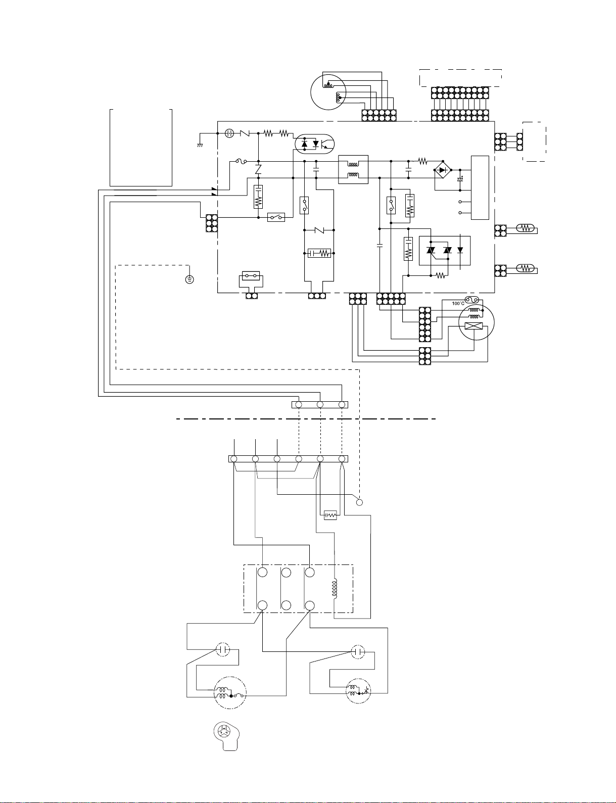
3-2. RAS-18UFP-E5 / RAS-18NA-E, RAS-B18UFPX5 / RAS-18N2AX
COLOR IDENTIFICATION
BRW : BROWN
RED : RED
WHI : WHITE
YEL : YELLOW
BLU : BLUE
BLK : BLACK
GRY : GRAY
PNK : PINK
ORN : ORANGE
GRN&YEL : GREEN&
GRN : GREEN
PUR : PURPLE
YELLOW
BLK
WHI
RED
GRN&YEL
BLK
CN30
CN31
P04
CN27
11
33
SG01
F01
T6.3A
When you use float
R09 R507
R22
FUSE
250VAC
R21
CR02
J401
21 1 1232
CN402 CN401 CN11
FOR FLOAT SWITCH
(OPTION)
switch you should
cut J401
RY04
LOUVER
MOTOR
FOR DRAIN PUMP
IC04
RY401
R405
CR401
(OPTION)
C15
ORN
RED
PNK
YEL
BRW
BLU
654
L01
123
654
C501
321
321
MAIN PCB
MCC-865A
RY501
5 3
5 311
BRW
GRY
YEL
BLK
CN07
3
INFRARED RAYS RECEIVE
AND INDICATION PARTS
123
CN25
123
BLU
123
CN13
123
R01
C01
CR502
CR501
R506
CN10 BLK
WHI
1 1
RED
3 3
6 6
3 3
2 2
1 1
BLU
DB01
BLU
C02
DC12V
DC5V
IC03
WHI
RED
PUR
456
456
BLU
BLU
456
456
BLU
GRY
BLU
789
7891010
BLU
BLU
BLU
789
7891010
POWER SUPPLY
WHI
CN100
CIRCUIT
CN03
1 1
2 2
CN01
1 1
2 2
CN101
WHI
11
GRY
22
GRY
33
BLK
BLK
BLK
BLK
FAN
MOTOR
SWITCH
1
PCB
2
3
MCC-865B
THERMO
SENSOR
(TA)
HEAT
EXCHANGER
SENSOR
(TC)
OUTDOOR
TERMINAL
BLOCK
RED
WHI
PNK
POWER SUPPLY
220 − 240 V ~ 50 Hz
L
BLK
MAGNETIC
CONTACTOR
CAPACITOR
S
R
COMPRESSOR
C
S
R
BLK
RED
INDOOR
TERMINAL
BLOCK
N
RED
i
1
1
GRN&YEL
RED
2
3
2
3
BLK
BLK
CHASSIS
GRN&YEL
i
INDOOR
UNIT
OUTDOOR
UNIT
SPARK KILLER
GRY
R
U
T
S
W
V
(or A)
A1
(or B)
A2
CAPACITOR
RED
C
BLK
WHI
RED
BLK
FAN MOTOR
COMPRESSOR TERMINAL
− 10 −
3-3. RAS-24UFHP-E5 / RAS-24NAH-E
FILE NO. SVM-06006
COLOR IDENTIFICATION
BRW : BROWN
RED : RED
WHI : WHITE
YEL : YELLOW
BLU : BLUE
BLK : BLACK
GRY : GRAY
PNK : PINK
ORN : ORANGE
GRN&YEL : GREEN&
GRN : GREEN
PUR : PURPLE
YELLOW
BLK
WHI
RED
GRN&YEL
BLK
CN30
CN31
CN23
P04
SG01
R22
F01
FUSE
T6.3A
250VAC
J401
2
1 1 1232 3
FOR FLOAT SWITCH
(OPTION)
When you use float
switch you should
cut J401
LOUVER
MOTOR
R09 R507
R21
CN402 CN401 CN11
IC04
C15
RY401
R405
CR401
FOR DRAIN PUMP
(OPTION)
CN07
L01
123
ORN
RED
PNK
YEL
BRW
BLU
654
654
C501
321
321
MAIN PCB
MCC-865A
RY501
5 3
5 311
BRW
GRY
YEL
CN25
CN13
R01
C01
CR502
CR501
CN10 BLK
WHI
1 1
RED
3 3
BLK
6 6
3 3
2 2
1 1
INFRARED RAYS RECEIVE
AND INDICATION PARTS
123
456
BLU
DC12V
DC5V
IC03
BLU
WHI
RED
456
BLU
456
456
C02
PUR
GRY
BLU
BLU
789
7891010
BLU
BLU
789
7891010
BLU
BLU
POWER SUPPLY
123
BLU
123
123
DB01
R506
WHI
CN100
CIRCUIT
CN03
1 1
2 2
CN01
1 1
2 2
CN101
WHI
11
GRY
22
GRY
33
BLK
BLK
BLK
BLK
FAN
MOTOR
SWITCH
1
PCB
2
3
MCC-865B
THERMO
SENSOR
(TA)
HEAT
EXCHANGER
SENSOR
(TC)
OUTDOOR
TERMINAL
BLOCK
C
S
R
COMPRESSOR TERMINAL
POWER SUPPLY
220- 240 V ~ 50 Hz
L
BLK
RED
BLK
RED
WHI
PNK
COMPRESSOR
INDOOR
TERMINAL
BLOCK
i
N
FERRITE CORE
RED
MAGNETIC
CONTACTOR
R
S
1
1
GRN&YEL
T
A1
2
3
2
3
i
CHASSIS
INDOOR
UNIT
OUTDOOR
UNIT
GRN&YEL
52C
BLK
A2
W
RED
WHI
RED
FAN MOTOR
U
V
CAPACITOR CAPACITOR
S
C
R
TRANSFORMER
COIL FOR
4 WAY VALVE
BLK
BLK
RED
RED
BLK
BLK
WHI
RED
GRY
BLU
YEL
BLU
BLU
1
3
1
3
1
3
5
7
9
1
313
11
33
MAIN P.C. BOARD (MCC-890)
1
2
CN06
3
1
CN05
3
SG01
1
F01
3
250VAC T6. 3A
5
CN01
7
9
CN11
CR11
CN02
CR12
CR13
BLK BLK
TNR
R74
CN03
1
1
RY07
RY05
3
TNR
R73
RY06
CN07
CN08
DISCHARGE
PIPE
SENSOR (TD)
BLU
1
1
2
3
3
BLU
BLK
1
1
2
3
3
BLK
HEAT
EXCHANGER
SENSOR (TE)
− 11 −

3-4. RAS-24UFP-E5 / RAS-24NA-E
RAS-24UFPX5 / RAS-24N2AX
FILE NO. SVM-06006
COLOR IDENTIFICATION
BRW : BROWN
RED : RED
WHI : WHITE
YEL : YELLOW
BLU : BLUE
BLK : BLACK
GRY : GRAY
PNK : PINK
ORN : ORANGE
GRN&YEL : GREEN&
GRN : GREEN
PUR : PURPLE
YELLOW
BLK
WHI
RED
GRN&YEL
CN30
CN31
BLK
P04
CN27
11
33
SG01
R22
F01
FUSE
T6.3A
250VAC
J401
21 1 1232
CN402 CN401 CN11
FOR FLOAT SWITCH
(OPTION)
When you use float
switch you should
cut J401
R09 R507
R21
CR02
RY04
LOUVER
MOTOR
FOR DRAIN PUMP
IC04
RY401
R405
CR401
(OPTION)
C15
ORN
RED
PNK
YEL
BRW
BLU
654
L01
123
654
C501
321
321
MAIN PCB
MCC-865A
RY501
5 3
5 311
BRW
GRY
YEL
BLK
CN07
3
INFRARED RAYS RECEIVE
AND INDICATION PARTS
123
CN25
123
BLU
BLU
123
CN13
123
R01
DB01
C01
CR502
DC12V
DC5V
CR501
CN10 BLK
WHI
RED
IC03
R506
1 1
3 3
6 6
3 3
2 2
1 1
BLU
WHI
RED
456
456
BLU
456
456
C02
PUR
GRY
BLU
BLU
BLU
789
789
BLU
BLU
789
789
10
10
BLU
WHI
10
10
POWER SUPPLY
CIRCUIT
CN100
CN03
1 1
2 2
CN01
1 1
2 2
WHI
11
GRY
22
GRY
33
BLK
BLK
BLK
BLK
FAN
MOTOR
CN101
SWITCH
1
2
3
MCC-865B
THERMO
SENSOR
(TA)
HEAT
EXCHANGER
SENSOR
(TC)
PCB
OUTDOOR
TERMINAL
BLOCK
POWER SUPPLY
220 − 240 V ~ 50 Hz
L
BLK
BLK
RED
INDOOR
TERMINAL
BLOCK
N
1
1
RED
BLK BLK
SPARK KILLER
A2 A1
52C
RED
1/L1 2/T1
3/L2 4/T2
5/L3 6/T3
MAGNETIC CONTACTOR
2
2
GRN&YEL
RED
CAPACITOR
3
3
GRY
CHASSIS
RED
CAPACITOR
WHI
PNK
COMPRESSOR
INDOOR
UNIT
OUTDOOR
UNIT
S
R
WHI
RED
BLK
C
COMPRESSOR TERMINAL
FAN MOTOR
C
S
R
BLK
− 12 −

FILE NO. SVM-06006
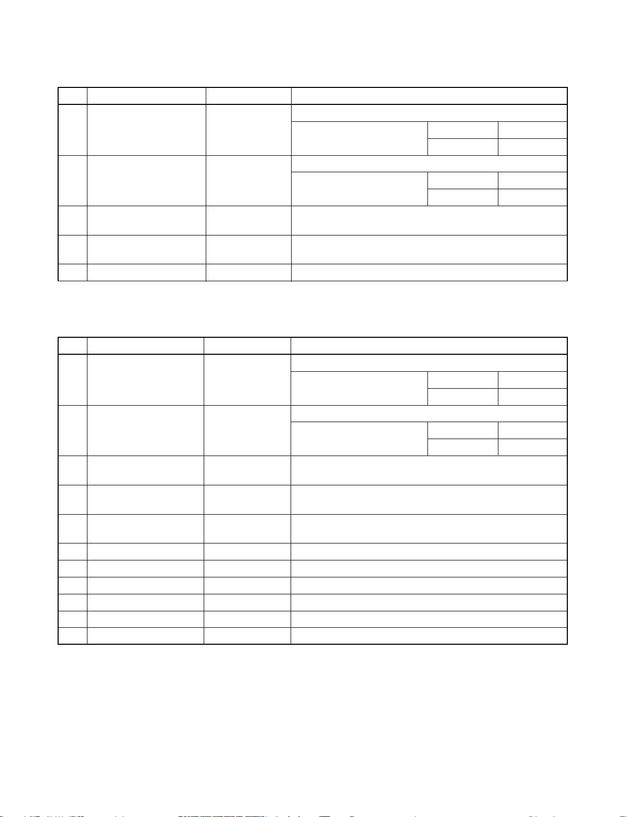
4. SPECIFICATION OF ELECTRICAL PARTS
4-1. Indoor Unit
No. Parts name Type Specifications
1 Fan motor (for indoor) AFP-220-50-4A Output (Rated) 50W, 220-240V
2 Thermo sensor (TA-sensor) ——— 10kΩ at 25°C
3 DC-DC transformer (T01) SWT-47 DC 390V, Secondary DC 12V, 7V
4 Microcomputer TMP87CM40AN
Heat exchanger sensor
5
(TC-sensor)
6 Line filter (L01) SS11V-R07190 19mH, AC0.7A
7 Diode (DB01) D3SBA60 4A, 600V
8 Capacitor (C02) KMH400VSSN47M22S 47µF, 400V
9 Fuse (F01) TSCR T6.3A, 250V
10 Varistor (R21, R22) TND15G561K 560V
11 Resistor (R01) RF-2TK5R6 5.6Ω, 2W
12 Louver motor MP35EA12
——— 10kΩ at 25°C
Output (Rated) 2W, 6poles, 4phase,
DC 12V
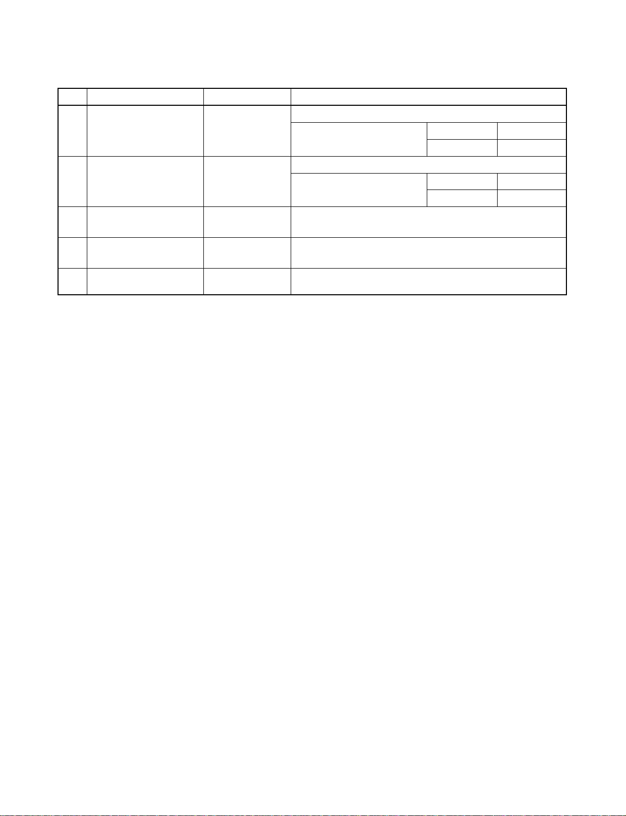
4-2. Outdoor Unit (RAS-18NAH-E)
No. Parts name Type Specifications
Output (Rated) 1500 W, 2 poles, 1 phase, 220 – 240 V, 50 Hz
1 Compressor PH340X3C-4KT1 Winding resistance (Ω) C-R C-S
(at 20°C) 1.46 2.47
Output (Rated) 42 W, 4 poles, 1 phase, 220 – 240 V, 50 Hz
2 Fan motor (for outdoor) FG-240-42A-1 Winding resistance (Ω) Red-Black White-Black
(at 20°C) 128 126
Running capacitor
3
(for fan motor)
Running capacitor
4
(for compressor)
Solenoid coil
5
(for 4-way valve)
6 Thermo sensor TE / TD 10 kΩ at 25°C / 50 kΩ at 25°C
7 Magnetic contactor
8 Transformer TT-05 220 – 240 V
9 Microcontroller TMP47C840N
10 Varistor (R73, R74, R86) 15G471K 470 V
11 Fuse (F01) MT3 T6.3 A, 250 V
451305L AC 450 V, 3.0µF
RS44B506U0218S AC 440 V, 50µF
VHV (STF) AC 220 – 240 V
CLK-26J
220 − 240 V, 50 Hz
– 13 –
FILE NO. SVM-0600
4-3. Outdoor Unit (RAS-18NA-E, RAS-18N2AX)
No. Parts name Type Specifications
Output (Rated) 1500 W, 2 poles, 1 phase, 220 – 240 V, 50 Hz
1 Compressor PH340X3C-4KT1 Winding resistance (Ω) C-R C-S
(at 20°C) 1.46 2.47
Output (Rated) 42 W, 6 poles, 1 phase, 220 – 240 V, 50 Hz
2 Fan motor (for outdoor) WLF-240-42A-1 Winding resistance (Ω) Red-Black White-Black
(at 20°C) 188 289
Running capacitor
3
(for fan motor)
Running capacitor
4
(for compressor)
5 Magnetic contactor CLK-26J 220 – 240 V, 50 Hz
4-4. Outdoor Unit (RAS-24NAH-E)
451205L AC 450 V, 2.0µF
RS44B506U0218S AC 440 V, 50µF
No. Parts name Type Specifications
Output (Rated) 2200 W, 2 poles, 1 phase, 220 – 240 V, 50 Hz
1 Compressor PH400X3CS-4KT1 Winding resistance (Ω) C-R C-S
(at 20°C) 1.13 2.10
Output (Rated) 42 W, 4 poles, 1 phase, 220 – 240 V, 50 Hz
2 Fan motor (for outdoor) FG-240-42A-1 Winding resistance (Ω) Red-Black White-Black
(at 20°C) 128 126
Running capacitor
3
(for fan motor)
Running capacitor
4
(for compressor)
Solenoid coil
5
(for 4-way valve)
6 Thermo sensor TE / TD 10 kΩ at 25°C / 50 kΩ at 25°C
7 Magnetic contactor A35 220 − 240 V, 50 Hz
8 Transformer TT-05 220 – 240 V
9 Microcontroller TMP47C840N
10 Varistor (R73, R74, R86) 15G471K 470 V
11 Fuse (F01) MT3 T6.3 A, 250 V
451405L AC 450 V, 4.0µF
RS44B506K0218S AC 440 V, 50µF
VHV (STF) AC 220 – 240 V
– 14 –
FILE NO. SVM-06006
4-5. Outdoor Unit (RAS-24NA-E, RAS-24N2AX)
No. Parts name Type Specifications
Output (Rated) 2200 W, 2 poles, 1 phase, 220 − 240 V, 50 Hz
1 Compressor PH400X3CS-4KT1 Winding resistance (Ω ) C-R C-S
2 Fan motor (for outdoor)
Running capacitor
3
(for fan motor)
FG-240-42A
451305L
(at 20 °C)
Output (Rated) 42 W, 4 poles, 1 phase, 220 − 240 V, 50 Hz
Winding resistance (Ω) Red-Black White-Black
(at 20 °C)
AC 450 V, 3.0µF
1.13
128 126
2.10
Running capacitor
4
(for compressor)
5 Magnetic contactor
RS44B506U0218S
A35
AC 440 V, 50µF
220 − 240 V, 50 Hz
– 15 –

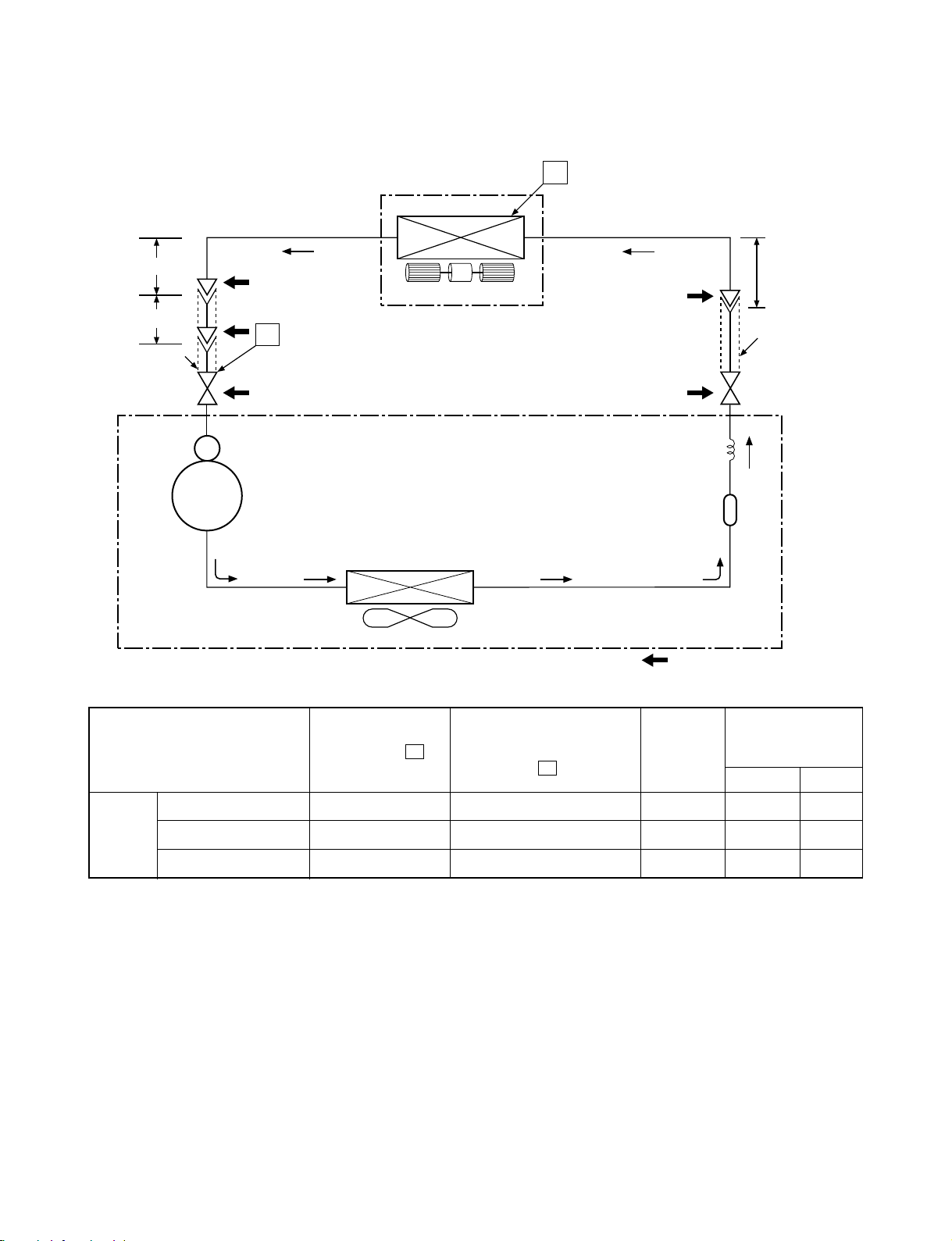
5. REFRIGERATION CYCLE DIAGRAM
5-1. RAS-18UFHP-E5 / RAS-18NAH-E
FILE NO. SVM-06006
0.39m
(Connecting pipe)
∅12.70 mm
0.39m
(Flexible pipe)
∅ 12.70 mm
O.D.:12.70 mm
Cooling
Heating
Cooling
Heating
Packed valve
Heating
4-way valve
Cooling
P
(∅12.70)
Compressor
PH340X3C-4KT1
Accumulator
Indoor unit
Evaporator
Multi blade fan
T
Capillary tube
∅0.6x600l
Packed valve
(∅
6.35)
Capillary tube
∅
2.0x1400l
0.49m
(Connecting pipe)
∅
6.35 mm
O.D.:6.35 mm
Condenser
Refrigerant
R-22 1.53kg
Fan speed
(indoor)
Ambient temp.
conditions DB/WB
(°C)
Indoor Outdoor
50Hz
Cooling
Heating
Propeller fan
Outdoor unit
Standard
pressure P
(MPaG)
Mark ( ) means check points of Gas Leak
Surface temp. of heat
exchanger interchanging
pipe T (°C)
Standard 1.66 43 High 20/– 7/6
Heating High temperature*1 2.18 ~ 2.34 47 ~ 55 Low 27/– 24/18
Low temperature 1.20 34.0 High 20/– –10/–10
Standard 0.48 10.8 High 27/19 35/24
Cooling High temperature 0.60 15.0 High 32/23 43/26
Low temperature 0.32 1.8 Low 21/15 21/15
Note : Measure the heat exchanger temperature at the center of U-bend. (By means of TC sensor.)
*1 : During heating overload, the high temperature limit control operation is included.
– 16 –
5-2. RAS-18UFP-E5 / RAS-18NA-E
RAS-B18UFPX5 / RAS-18N2AX
FILE NO. SVM-06006
0.39m
(Connecting pipe)
∅12.70 mm
0.39m
(Flexible pipe)
∅12.70 mm
O.D.:12.70 mm
Compressor
P
Packed valve
(∅12.70)
PH340X3C-4KT1
Indoor unit
Evaporator
Multi blade fan
Condenser
Propeller fan
Outdoor unit
T
0.49m
(Connecting pipe)
∅6.35 mm
O.D.:6.35 mm
Packed valve
(∅6.35)
Capillary tube
2.0x600
∅
Refrigerant
R-22 1.00 kg
Mark ( ) means check points of Gas Leak
S
Dryer
Ambient temp.
conditions DB/WB
(°C)
Indoor Outdoor
50Hz
Standard
pressure P
(MPaG)
Surface temp. of heat
exchanger interchanging
pipe T (°C)
Fan speed
(indoor)
Standard 0.41 11.0 High 27/19 35/24
Cooling High temperature 0.56 15.0 High 32/23 43/26
Low temperature 0.32 2.0 Low 21/15 21/15
Note : Measure the heat exchanger temperature at the center of U-bend. (By means of TC sensor.)
– 17–

5-3. RAS-24UFHP-E5 / RAS-24NAH-E
FILE NO. SVM-06006
0.39m
(Connecting pipe)
∅15.88 mm
0.39m
(Flexible pipe)
∅15.88 mm
O.D.:15.88 mm
Cooling
Heating
Cooling
Heating
Packed valve
Heating
4-way valve
Cooling
P
(∅15.88)
Compressor
PH400X3CS-4KT1
Accumulator
Multi blade fan
Condenser
Indoor unit
Evaporator
T
0.49m
(Connecting pipe)
∅6.35 mm
O.D.:6.35 mm
Packed valve
(∅6.35)
Capillary tube
∅1.0x1200S
Capillary tube
∅2.0x1400S
Refrigerant
R-22 2.00kg
Fan speed
(indoor)
Ambient temp.
conditions DB/WB
Indoor Outdoor
50Hz
Cooling
Heating
Propeller fan
Outdoor unit
Standard
pressure P
(MPaG)
Mark ( ) means check points of Gas Leak
Surface temp. of heat
exchanger interchanging
pipe T (°C)
Standard 0.32 43.5 High 20/– 7/6
Heating High temperature*1
Low temperature
Standard
0.18 38.4 High 20/––
Cooling High temperature 0.
Low temperature
0.51 58.9 Low 27/– 24/18
0.4
3 11.0 High 27/19 35/24
59 15.7 High 32/23 43/26
0.3
4 1.4 Low 21/15 21/15
Note : Measure the heat exchanger temperature at the center of U-bend. (By means of TC sensor.)
*1 : During heating overload, the high temperature limit control operation is included.
(°C)
10/–10
– 18 –

5-4. RAS-24UFP-E5 / RAS-24NA-E
RAS-24UFPX5 / RAS-24N2AX
FILE NO. SVM-06006
0.39m
(Connecting pipe)
∅15.88 mm
0.39m
(Flexible pipe)
∅15.88 mm
O.D.:15.88 mm
Cooling
Compressor
P
Packed valve
(∅15.88 )
PH400X3CS-4KT1
Indoor unit
Evaporator
Multi blade fan
T
0.49m
(Connecting pipe)
∅6.35 mm
O.D.:6.35 mm
Packed valve
(∅6.35)
Capillary tube
∅2.4x700S
Fan speed
(indoor)
Ambient temp.
conditions DB/WB
(°C)
Indoor Outdoor
50Hz
Condenser
Propeller fan
Outdoor unit
Standard
pressure P
(MPaG)
Refrigerant
R-22 1.68kg
Mark ( ) means check points of Gas Leak
Surface temp. of heat
exchanger interchanging
pipe T (°C)
Standard 0.43 11.0 High 27/19 35/24
Cooling High temperature 0.56 12.0 High 32/23 43/26
Low temperature 0.30 1.0 Low 21/15 21/15
Note : Measure the heat exchanger temperature at the center of U-bend. (By means of TC sensor.
– 19 –
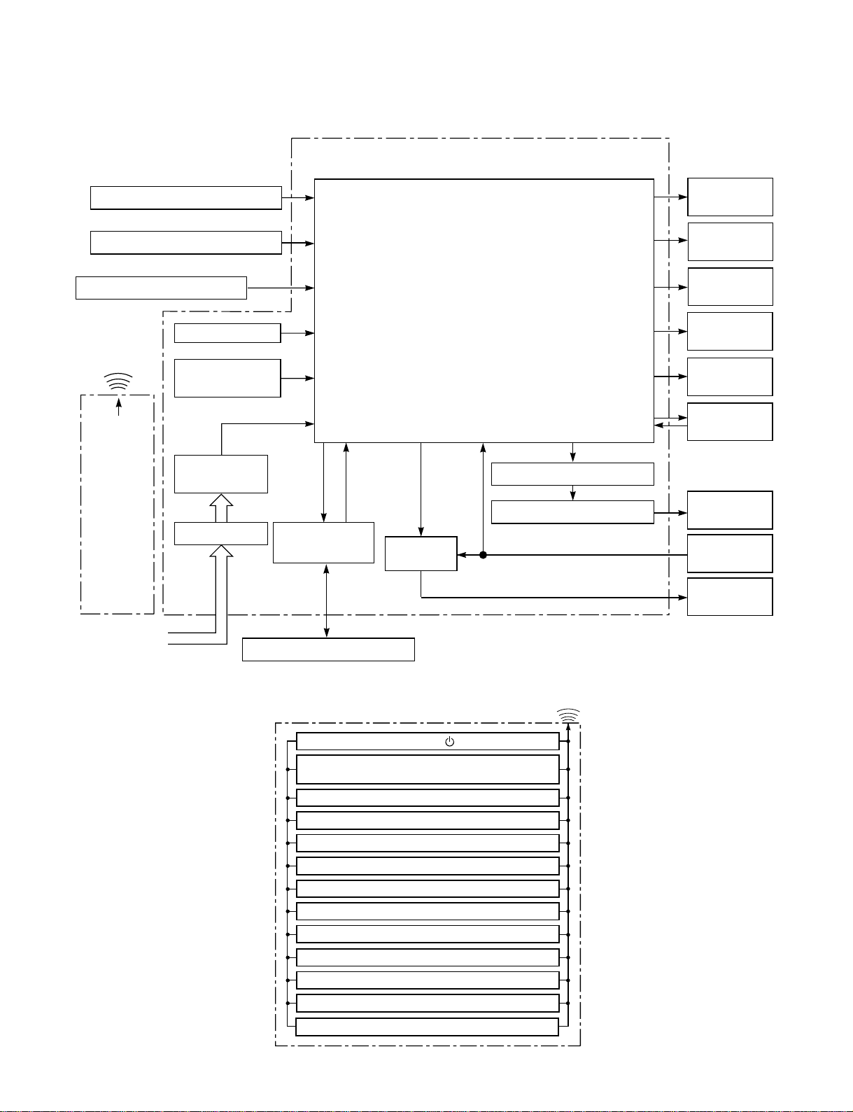
6. CONTROL BLOCK DIAGRAM
6-1. RAS-18UFHP-E5, RAS-24UFHP-E5
Indoor Unit Control Panel
Heat Exchanger Sensor
Temperature Sensor
Functions
• Louver Control
• 3-minute Delay at Restart for Compressor
FILE NO. SVM-06006
8 MHzM.C.U.
Hi POWER
Display
FILTER Sign
Display
Infrared Rays Signal Receiver
Initiallizing Circuit
Infrared
Rays
36.7 kHz
Clock Frequence
Oscillator Circuit
Power Supply
Remote
Circuit
Control
Noise Filter
From Outdoor Unit
• Motor Revolution Control
• Processing
(Temperature Processing)
• Timer
• Drain Pump ON/OFF
• Serial Signal Communication
Serial Signal
Transmitter/
Receiver
Serial Signal Communication
Relay
RY401
Louver ON/OFF Signal
Louver Driver
PRE DEF.
Sign Display
TIMER
Display
OPERATION
Display
Indoor Fan
Motor
Louver Motor
Float
Switch
Drain
Pump
REMOTE CONTROL
Infrared Rays
Remote Control
Operation ( )Operation ( )
Operation Mode Selection
AUTO, COOL, DRY, HEAT, FAN ONLY
Temperature Setting
Fan Speed Selection
ON TIMER Setting
OFF TIMER Setting
Louver Auto Swing
Louver Direction Setting
ECO
Hi power
TIMER 1.3.5.9H
COMFORT SLEEP
QUIET
– 20 –

6-2. RAS-18UFP-E5, RAS-B18UFPX5,
RAS-24UFP-E5, RAS-24UFPX5
Indoor Unit Control Panel
Heat Exchanger Sensor
Temperature Sensor
Functions
• Louver Control
• 3-minute Delay at Restart for Compressor
FILE NO. SVM-06006
8 MHzM.C.U.
Hi POWER
Display
FILTER Sign
Display
Infrared Rays Signal Receiver
Initiallizing Circuit
Infrared
Rays
36.7 kHz
Clock Frequency
Oscillator Circuit
Power Supply
Circuit
Remote
Control
Noise Filter
From Outdoor Unit
• Motor Revolution Control
• Processing
(Temperature Processing)
• Timer
• Drain Pump ON/OFF
• Compressor ON/OFF
Driver
Relay
RY04
Compressor
Relay
RY401
Louver ON/OFF Signal
Louver Driver
FAN-ONLY
Sign Display
TIMER
Display
OPERATION
Display
Indoor Fan
Motor
Louver Motor
Float
Switch
Drain
Pump
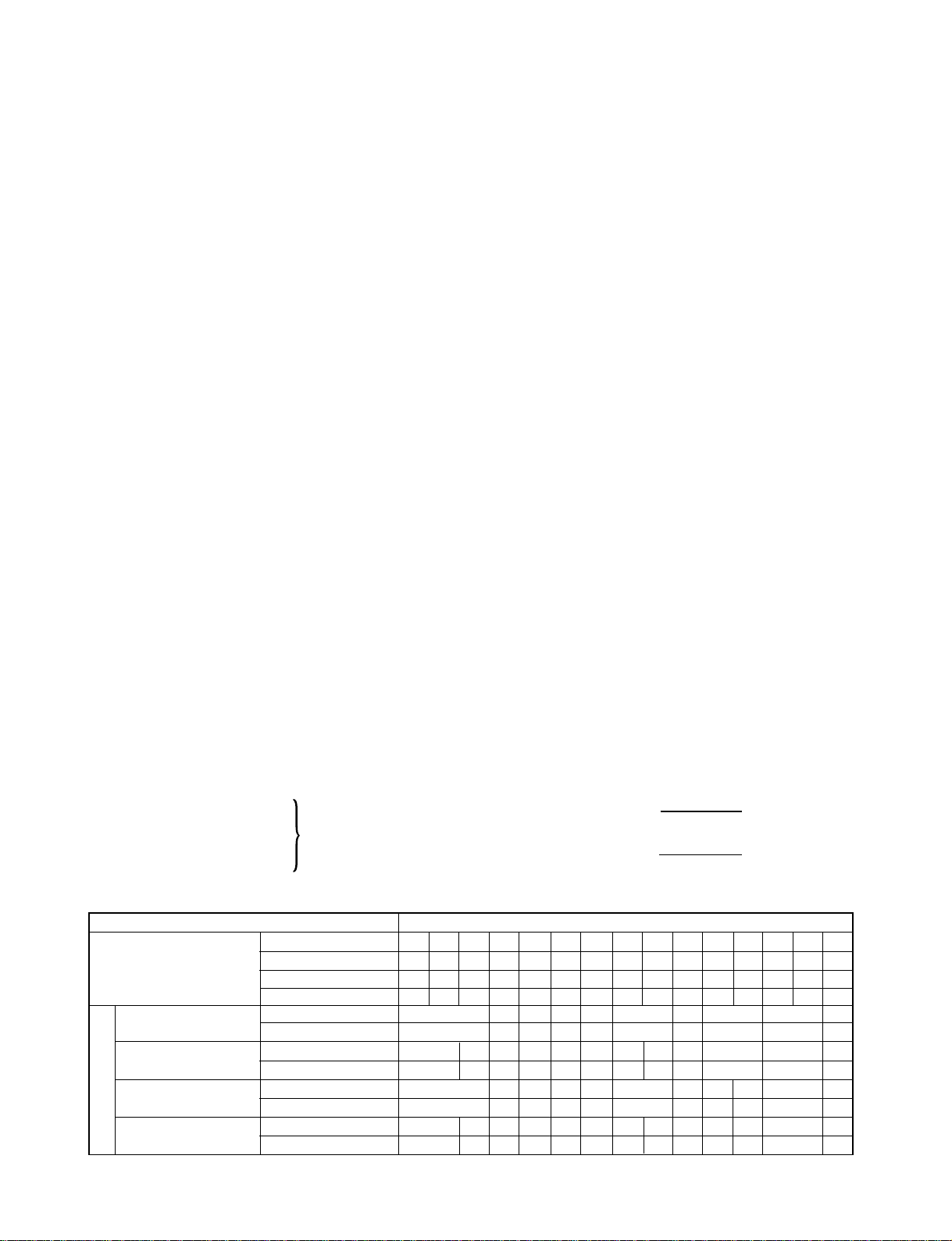
REMOTE CONTROL
Infrared Rays
Remote Control
Operation ( )Operation ( )
Operation Mode Selection
AUTO, COOL, DRY, FAN ONLY
Temperature Setting
Fan Speed Selection
ON TIMER Setting
OFF TIMER Setting
Louver Auto Swing
Louver Direction Setting
ECO
Hi power
TIMER 1.3.5.9H
COMFORT SLEEP
QUIET
– 21 –
7. OPERATION DESCRIPTION
FILE NO. SVM-06006
7-1. Outline of Air Conditioner Control
This is a fixed capacity type air conditioner, which uses
a AC motor for an indoor fan. The AC motor drive
circuit is mounted in the indoor unit. And electrical
parts which operate the compressor and the outdoor
fan motor, are mounted in the outdoor unit.
The air conditioner is mainly controlled by the indoor
unit controller. The controller operates the indoor fan
motor based upon commands transmitted by the
remote control and transfers the operation commands
to the outdoor unit controller.
The outdoor unit controller receives operation
commands from the indoor unit, and operates the
outdoor fan motor and the compressor.
(1) Role of indoor unit controller
The indoor unit controller receives the operation
commands from the remote control and executes
them.
• Temperature measurement at the air inlet of the
indoor heat exchanger by the indoor
temperature sensor
• Temperature setting of the indoor heat
exchanger by the heat exchanger sensor
• Louver motor control
• Indoor fan motor operation control
• LED display control
• Transferring of operation commands to the
outdoor unit
• Receiving of information of the operation status
and judging of the information or indication of
error
(2) Role of outdoor unit controller
The outdoor unit controller receives the operation
commands from the indoor controller and
executes them.
• Compressor operation
control
• Operation control of
outdoor fan motor
Operations according
to the commands
from the indoor unit
• Turning off the compressor and outdoor fan
when the outdoor unit receives the shutdown
command
• Defrost control in heating operation
(Temperature measurement by the outdoor heat
exchanger and control for the four-way valve
and the outdoor fan motor) *Heat pump Model
only
7-1-1. Louver control
(1) Vertical air flow louver
Position of veritcal air flow louver is automatically
controlled according to the operation mode.
Besides, position of vertical air flow louver can be
arbitrarily set by pressing [FIX] button.
The louver position which is set by [FIX] button is
stored in the microcomputer, and the louver is
automatically set at the stored position for the next
operation.
(2) Swing
If [SWING] button is pressed when the indoor unit
is in operation, the vertical air flow louver starts
swinging. When [FIX] button is pressed, it stops
swinging.
7-1-2. Indoor fan control (AC Fan motor)
(1) The indoor fan is operated by the stepless speed
change AC motor.
(2) For air flow level, speed of the indoor fan motor is
controlled in five steps (LOW, LOW
+
, MED, MED
and HIGH). If AUTO mode is selected, the fan
motor speed is automatically controlled by the
difference between the preset temperature and
the room temperature.
LOW
=
LOW+MED
+
2
MED+=
MED+HIGH
2
+
OPERATION
MODE
RAS-18UFHP Series
RAS-18UFP Series
Model
RAS-24UFHP Series
RAS-24UFP Series
Table 7-1-1
FAN TAP
Cooling UH H M+
Heat
Fan only
Dry
rpm
Air flow volume (m3/h)
rpm
Air flow v
rpm
Air flow volume (m3/h)
rpm
Air flow volume (m3/h)
olume (m
3
/h)
UH H
1120
830
−
1120
830
−
1090
1210
930
−
1210
930 660
−
H
1060
800
1060
800
1170
900
1170
900
M+
M+
1030
770 720
1030
770
920
1090
810
M
L
L+
M
M
M
970
950 820
700
−
900
−
680
1000
1020
760
750
−
1000
750
−
600
−
−
860
660
−
−
− 22 −
L
L+
LL+
L
L
L+
800
580
820
800
600
580
850
650
860
850
650
L
L- SUL/SL-
UL
L-
L- UL SUL
480
690
480
600
410
600
410
640
440
640
440
700
490
700
490
650
450
650
450
690
SUL/SL-
500
320
−
−
540
350
−
−

FILE NO. SVM-06006
7-2. Description of Operation Circuit
(1) When turning on the breaker, the operation lamp
blinks. This means that the power is on (or the
power supply is cut off.)
(2) When pressing [ ] button on the
remote control, receiving beep sounds from the
indoor unit, and the next operation is performed
together with opening the vertical air flow louver.
(3) Once the operation mode is set, it is memorized in
the microcomputer so that the previous operation
can be effected thereafter simply by pressing
[ ] button.
7-2-1. Fan only operation
([MODE] button on the remote control is set
to the fan only operation.)
(1) When [FAN] button is set to AUTO, the indoor fan
motor operates as shown in Fig. 7-2-1. When
[FAN] button is set to LOW, LOW+, MED, MED+ or
HIGH, the motor operates with a constant air flow.
°C
7-2-2. Cooling operation
([MODE] button on the remote control is set
to the cooling operation.)
(1) The compressor, 4-way valve, outdoor fan and
operation display lamp are controlled as shown in
Fig. 7-2-2.
°C
ON ON
OFF OFF OFF ON
4-way valve
Compressor
Outdoor fan
(Room temp.) (Preset temp.)
Preset
temp.
0.5
0
Fig. 7-2-2
display lamp
OPERATION
+3
+2.5
+2
+1.5
+1
+0.5
(Room temp.) − (Preset temp.)
Preset
temp.
0
(Preset temp.: 24°C)
NOTE :
*1: The values marked with *1 are calculated and
controlled by the difference in motor speed
between M+ and L–.
(2) The Hi POWER, ECO and COMFORT SLEEP
operation cannot be set.
Fig. 7-2-1 Setting of air flow [FAN:AUTO]
M+
*1
*1
*1
(2) When [FAN] button is set to AUTO, the indoor fan
motor operates as shown in Fig. 7-2-3. When
[FAN] button is set to LOW, LOW+, MED, MED+ or
HIGH, the motor operates with a constant air flow.
°C
(Room temp.) − (Preset temp.)
Preset
temp.
+3
+2.5
+2
+1.5
+1
+0.5
0
-0.5
M+
*1
*1
*1
NOTE :
*1: The values marked with *1 are calculated and
controlled by the difference in motor speed
between M+ and L–.
Fig. 7-2-3 Setting of air flow [FAN:AUTO]
– 23 –

FILE NO. SVM-06006
7-2-3. Dry operation
([MODE] button on the remote control is set
to the dry operation.)
(1) The compressor, 4-way valve, outdoor fan and
operation display lamp are controlled as shown in
Fig. 7-2-4.
°C
ON:6min.
OFF:4min.
ON
ON:5min.
OFF:5min.
OFF
4-way valve
Outdoor fan
(Room temp.) (Preset temp.)
Preset
temp.
+3
+2
+1
ON:6min.
OFF:4min.
OFF
ON:5min.
OFF:5min.
OFF
0
Compressor
Fig. 7-2-4
7-2-4. Heating operation *Heat pump model only
(1) The compressor, 4-way valve, outdoor fan and
Preset
temp.
display lamp
OPERATION
([MODE] button on the remote control is set
to the heating operation.)
operation display lamp are controlled as shown in
Fig. 7-2-6.
°C
0
ON
OFF
0.5
ON
(Room temp.) (Preset temp.)
OFF
ON
4-way valve
Compressor
Outdoor fan
ON
display lamp
OPERATION
Fig. 7-2-6
(2) The microprocessor turns the compressor on and
off at the regular intervals (4 to 6 minutes). While
the compressor is turning off, the indoor fan motor
operates in the SUPER LOW position.
The pattern of operation depending on the relation
between room temperature and preset
temperatures is shown in Fig. 7-2-5.
R oom temp.
Preset temp.+1
Preset temp.
Compressor
Outdoor fan
Indoor fan
ON ON ON ON
OFF OFF OFF
L. *S.L. S.L.L. L. S.L. L.
*Super Low
Fig. 7-2-5
(3) [FAN] button on the remote control is set to AUTO
only.
(2) When [FAN] button is set to AUTO, the indoor fan
motor operates as shown in Fig. 7-2-7. When
[FAN] button is set to LOW, LOW+, MED, MED+ or
HIGH, the motor operates with a constant air flow.
Preset
temp.
°C
0
-0.5
-1
-1.5
-2
-5.0
-5.5
[FAN AUTO]
(Room temp.) − (Preset temp.)
L
*1
*2
+
M
H
*1, *2 : The values marked with *1 and *2 are
calculated and controlled by the difference in
motor speed between M+ and L.
Fig. 7-2-7 Setting of air flow [FAN:AUTO]
(4) The ECO and Hi Power operations can not be set.
– 24 –

FILE NO. SVM-06006
(3) The indoor heat exchanger restricts revolving
speed of the fan motor to prevent a cold draft. The
upper limit of the revolving speed is shown in
Fig. 7-2-8 and Table 7-2-1.
Manual
(One of
AUTO
*4
SUL*
SUL*1
Stop
5 speed)
L-H
(Up to
setting
3
speed)
*2
A+4 A+4
A-8 A-8
464534
33
33 21
32 20
*6 *5
NOTES :
*1: The fan stops for 2 minutes after thermostat-OFF.
*2: A is 24°C when the preset temperature is 24°C or
more and A is the preset temperature when it is
under 24°C.
*3: SUL means Super Ultra Low.
*4: Calculated from difference in motor speed
between SUL and HIGH.
7-2-5. Automatic operation
([MODE] button on the remote control is set
to the automatic operation.)
(1) One of 3 operations (Cooling, Fan only or Heating)
is selected according to difference between the
preset temperature and the room temperature at
which the automatic operation has started, as
shown in Fig. 7-2-9. The Fan only operation
continues until the room temperature reaches a
level at which another mode is selected.
(2) Temporary Auto
When the TEMPORARY button on the indoor unit
is pushed, the preset temperature is fixed at 24°C
and the indoor unit is controlled as shown in
Fig. 7-2-9.
°C
Cooling operation
The louver moves to the position same
as Hi POWER operation.
+4
Cooling operation
0
Fan only operation
-1
Fig. 7-2-8 Cold draft preventing control
*5 and *6:
Table 7-2-1
Fan *5 *6
speed Starting period Stabilized period
AUTO • Up until 12 minutes
passed after starting
the unit
• From 12 to 25 minutes
passed after starting
the unit and room
temperature is 3°C
lower than preset
temperature
Manual • Room temperature
(L – H) < Preset temperature
• From 12 to 25 minutes
passed after starting
the unit and room
temperature is
between preset
temperature and 3°C
lower than preset
temperature
• 25 minutes or more
passed after starting
the unit
• Room temperature
Preset temperature
–4°C
–3.5°C
Heating operation
RAS-18UFHP-E5
(Room temp.) − (Preset temp.)
RAS-24UFHP-E5
RAS-18UFP-E5, RAS-B18UFPX5,
RAS-24UFP-E5, RAS-24UFPX5
Fig. 7-2-9
– 25 –
 Loading...