

Toshiba RAS-B10UFV-E, RAS-137SKV-E5, RAS-167SKV-E5, RAS-B16N3KVP-E, RAS-B13UFV-E Technical Handbook
...
Version 14.1.3
24 Hour Technical Helpline: 0870 843 0333
Fault & DN Code Apps: Android & iPhone
Web Page toshiba-calc.co.uk/fault-codes/
Fault Code Text Service: 07624 803 017
technical.enquiries@toshiba-ac.com
Technical HandBook

Page 2 of 78
Index Page
Make Up of Model Number 3
Mechanical Specifications-RAS R410A Outdoor Units 4
Performance & Electrical Specifications - RAS R410A Single Splits 4
Performance & Electrical Specifications - RAS R410A Multi Splits 4
RAS R410A Multi Split System Combinations 5
Acoustic Data - RAS Indoor Units 5
RAS - Auto Restart Function 6
Fault Codes - RAS “N” Series 6
Mechanical Specifications - DI/SDI R410A Single Splits 7
Performance & Electrical Specifications - DI / SDI R410A Single Splits 7
Electrical Specifications - DI/SDI R410A Multi Splits 8
Acoustic Data – DI/SDI Indoor Units 8
Mechanical & Electrical Data - Air-to-Air Heat Exchangers 9
Digital/Super Digital Replacement Refrigerant Pipe Sizing 10
Digital/Super Digital Inverter Multi Split System Combinations 11
Digital/Super Digital Inverter Twin Splits 12
Digital/Super Digital Inverter Triple Splits 14
Digital Inverter Quad Splits 16
Digital/Super Digital Multi Split System Wiring Schematic 17
VRF System Make Up Chart 18
Electrical Data - VRF Outdoor Units 19
VRF Additional Refrigerant Charge Amount 19
VRF Additional Refrigerant Charge Calculations 20
Acoustic Data - MMY Indoor Units 23
Common Sensor Characteristics 24
Trouble Shooting - RAV Series 25
Apps Store Fault Codes - All Commercial & VRF Systems 28
Fault Codes – All Commercial & VRF Systems 29
Error Detected by TCC-Link Central Controller 43
Step By Step Wiping/Re-addressing Of VRF Systems 44
Priority Mode (SMMSi Only) 44
Outdoor Fan High Static Pressure Setup 44
Compressor or Outdoor Fan Motor Backup Isolation Setting 44
VRF Rotary Dial Data Display SMMSi, SHRMi & Mini SMMS 45
TCC-net Controller Guidelines 46
System Configuration Menu 47
TCCJ Optional Control Accessories 49
TCC-Net Control - Standard Wired Controller 50
Controller Configuration - Remote Controller RBC-AMT32E & RBC-AMS41E 51
Data Retrieval Guide - Remote Controllers RBC-AMT32E, RBC-AMS41E & RBC-AMS51E 52
Simplified Instructions for RBC-AMS41E Remote Controller 54
Time, Temperature & Mode Setting for RBC-AMS41E Remote Controller 55
Simplified Instructions for RBC-AMS51E Remote Controller 56
Fault Code Guide for RBC-AMS51E Remote Controller 57
Data Retrieval Guide - RBC-AMS51E Remote Controller 58
Relocation of Room Temperature Sensing from Return Air to Remote Controller 59
Automatic Restart after Power Failure 60
Condition Setting (Day, Time, Mode & Temperature) 62
Delete Settings for each Day 63
Copy Settings for Previous Day 63
Holiday Day Omit Setting 64
Energy Saving Function 64
VN Air to Air Heat Exchangers 66
VN Air to Air Heat Exchanger Configurations 68
Automatic Zone Registration Using the Central Remote Controller (TCB-SC642TLE) 69
Network Addressing DI/SDI and VRF Systems 70
Integration with AI Network Control 76
Second Controller 76
Temperature Sensing 76
E = CE marked
P = Made in Thailand
T = Twin rotary compressor
V = Single rotary compressor
R = Infrared option
Style
X = Flexi (Low Wall or Under-slung)
K = Hi Wall, C = Ceiling Suspended
U = Cassette, B = Ducted
A = Outdoor
RAV/RAS Products
RAS - 16 7 SK_PE
Digital/Super Digital Inverter
RAV-SM566KRTP-E
SMMSi/SHRMi
MMYMAP 1204HT8E
Modular Multi Indoor Units
MM* - AP 056 4 BH E
009= 2.8kW 012= 3.6kW 015= 4.5kW 018= 5.6kW 024= 7.1kW 027= 8kW 030= 9kW 036= 11.2kW 048= 14kW 056= 16kW
*Style
U = Cassette, F = Tall Floor standing
D = Ducted, C = Ceiling suspended
K = High Wall, L = Floor standing
Refrigerant R410A
Capacity Rank
MMY = Modular Multi
M = Single module
No mark = Combined model
Refrigerant R410A
Capacity rank HP x 10
E = CE marked
Three phase power supply
Capacity variable unit (Inverter)
H = Heat pump (two pipe)
F = Heat recovery (three pipe)
Development series
RAV = Light Commercial Range
SM = Digital Inverter
SP = Super Digital Inverter
Nominal Duty (kW) i.e. 56 = 5.6kW
Generation: 0 = original
3 = 3
rd
Update etc
RAV = Light Commercial Range
RAS = Small Office / Domestic
Approx Duty (x 1000 = BTU)
Generation
RAV use numbers i.e. 0,1,2,3,4,5
RAS use letters i.e. U,E,S,Y
E = CE marked
P = Made in Plymouth
Blank = Single Phase Power Supply
8 = Three Phase Power Supply
H = HP (RAV)
N = Chassis Type, K = High Wall
L = Console Type, C = Ceiling suspended
S = Low Wall, F = Tall Floor
B = Ducted Type, U = Four Way Cassette
A = Outdoor Unit TU = Two Way Cassette
E = CE marked
Style
WH = 2-way discharge, H = Heat pump
SH = 1-way discharge, SPH = Slim Duct
BH = Standard duct
Development series
Make Up of Model Number
Page 3 of 78
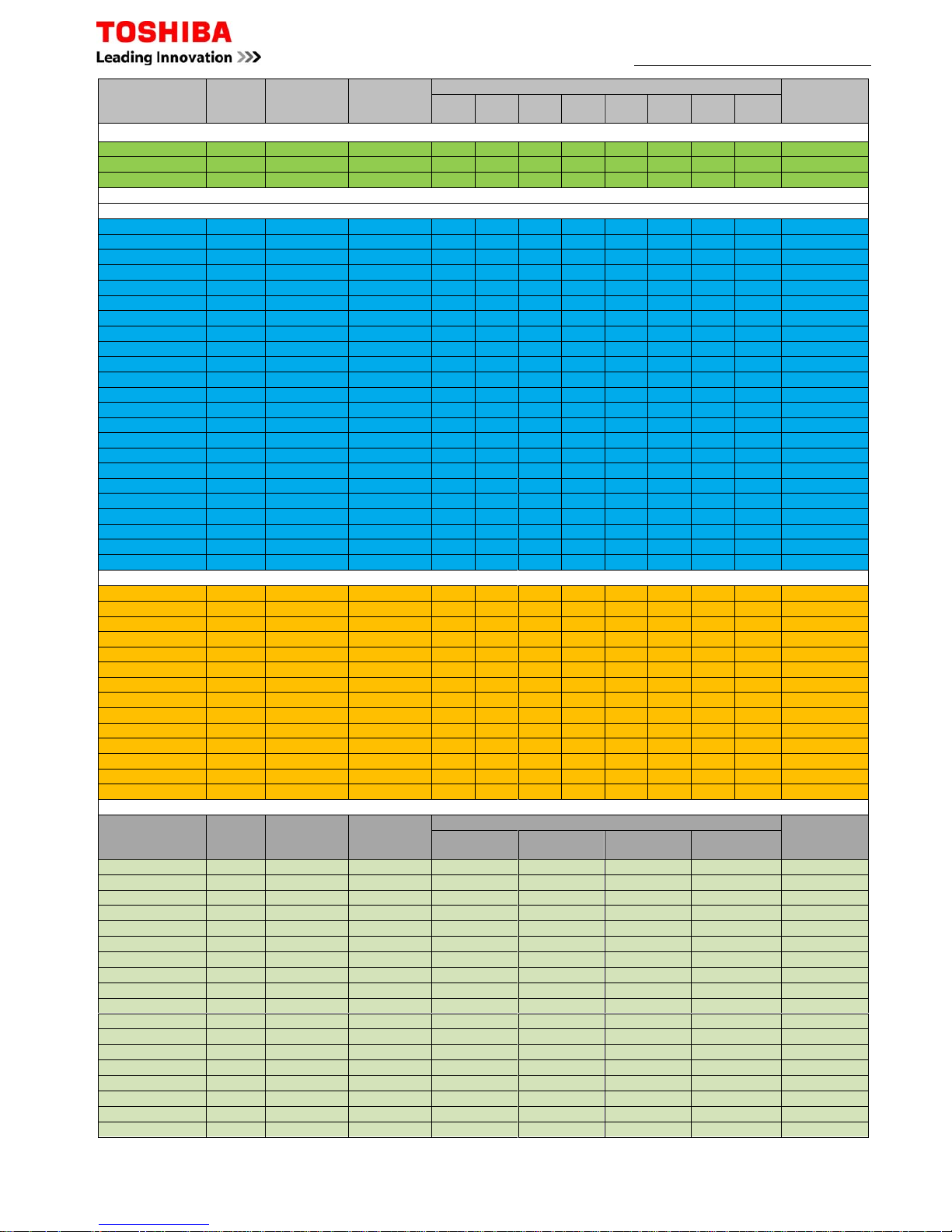
Mechanical Specifications - RAS R410A Outdoor Units
Page 4 of 78
Model
Pipe Sizes
Min/Max
Pipe Sep
(m)
Max
Height
Separation
Pre-
charge
(m)
Add
Charge
(g/m)
Base
Charge
(kg)
Dimensions
(mm)
Weight
(kg)
Liquid Suction
RAS Outdoor Units
RAS-107SAV
-
E6
1/4
3/8 2/15 8 15 N/A 0.63 530x660x240
27
RAS-137SAV
-E630
RAS-167SAV
-E51/2
2/20
10 15
20
1.05
550x780x290
40
RAS-10N3AVP
-
E
3/8
2/25 630x800x300 41
RAS-13N3AVP
-ERAS
-
16N3AVPE
1/2
RAS-10N3AV2
-
E
3/8
2/20 10 15 550x780x290
33
RAS-13N3AV2
-ERAS-16N3AV2
-E1/239RAS
-
M14GVAE
3/8
2/30 10 20
0.90
550x780x290
36
RAS-M18UAV
-
E
1/2
1.20
41
RAS-3M26UAV
-
E
70
15 40
2.40
890x900x320
69
RAS-4M27UAV
-ERAS-5M34UAV
-E180
2.99
75
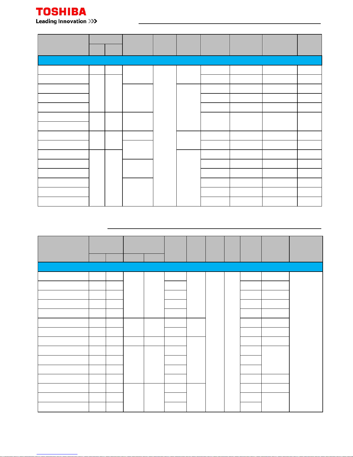
Performance & Electrical Specifications - RAS R410A Single Splits
Model
Capacity
(kW)
Sensible
Capacity
(kW)
Energy
Rating
Cool/Heat Phase
PowerToSoft
Start
Max
Current
Suggested
Fuse Size
Interconnect
Cable
Cool Heat
RAS Split Systems
RAS-107SAV-E6
2.50 3.20
2.13 A/A
1Ph + N Outdoor Yes
4.19 10
3Core + Earth
RAS-137SAV-E6 3.15 3.60 2.51 A/A 5.37 10
RAS-167SAV-E5 4.87 4.65 3.70 A+/A 7.58 16
RAS-10N3AVP-E
3.30 4.62
2.48 A+++/A+++ 3.42 10
RAS-13N3AVP-E 4.07 4.91 3.05 A++/A+ 4.78 10
RAS-16N3AVP-E
4.50 5.80
3.38 A++/A+ 7.12 16
RAS-10N3AV2-E
3.02 3.60
2.53 A++/A+ 3.60 10
RAS-13N3AV2-E 3.99 4.05 2.79 A++/A 5.66 10
RAS-18N3AV2-E
5.55 4.73
3.89 A+/A 8.79 16
Performance & Electrical Specifications - RAS R410A Multi Splits
Model
Min-Max
Indoors
Capacity (kW)
Energy
Rating
Cool/Heat
Phase
PowerToSoft
Start
Max
Current
Suggested
Fuse Size
Interconnect
Cable
Cool Heat
RAS Multi Systems
RAS-M14GAV-E 1 - 2 1.10 - 4.50 0.90 - 5.20 A+/A
1Ph + N Outdoor Yes
5.47 16
3Core +Earth
RAS-M18UAV-E 2 - 2 1.40 - 6.20 0.90 - 8.30 A++/A++ 7.93 16
RAS-3M26UAV-E 2 - 3 4.10 - 9.00 2.00 - 11.2 A++/A+ 11.37 20
RAS-4M27UAV-E 2 - 4 4.20 - 9.30 3.00 - 11.7 A++/A+ 11.99 20
RAS-5M34UAV-E1 2 - 5 3.70 - 11.0 3.40 - 14.0 A++/A+ 15.22 25
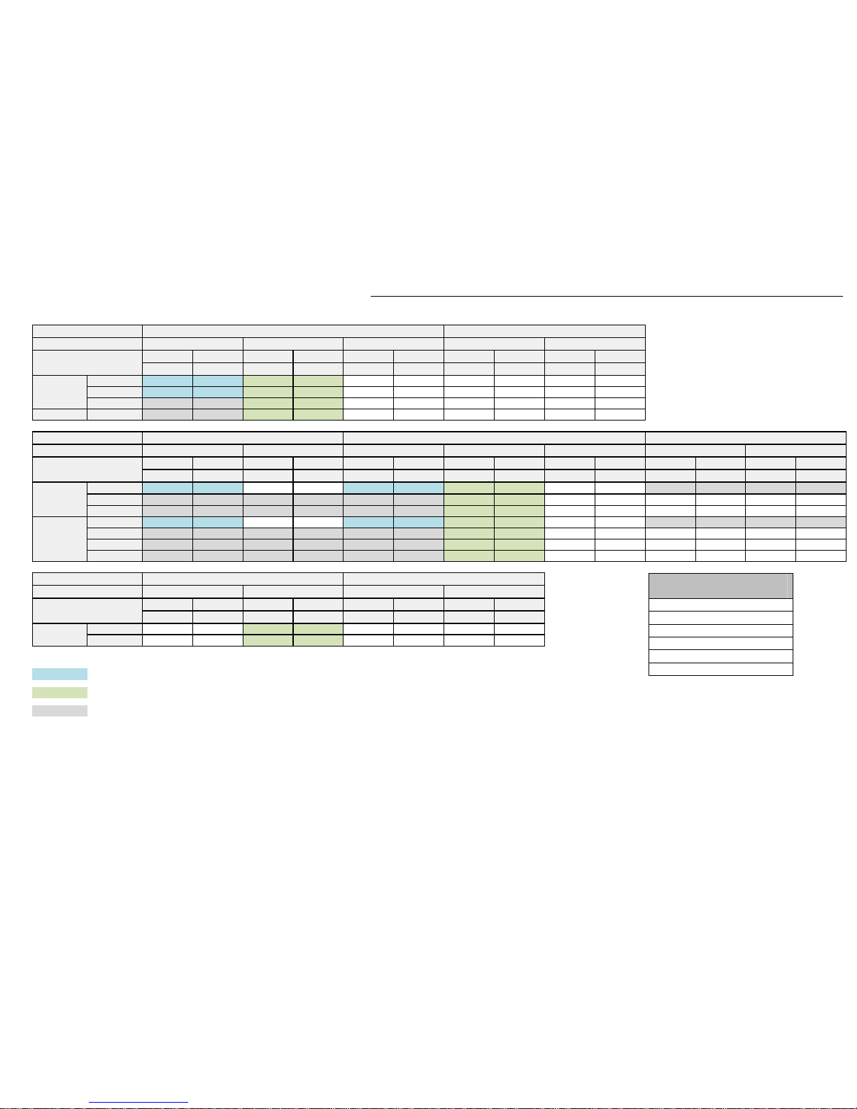
RAS R410A Multi Split System Combinations Examples
Unit 1 Unit 2 Unit 3 Unit 4 Unit 5
10 (1.95kw)
10 (1.95kw)
13 (2.33kw)
10 (1.95kw)
10 (2.55kw)
10 (2.55kw)
13 (2.95kw)
10 (2.15kw)
13 (2.55kw)
13 (2.55kw)
16 (3.19kw)
10 (1.91kw)
16 (2.85kw)
13 (2.35kw)
10 (2.40kw)
10 (2.40kw)
10 (2.40kw)
13 (3.01kw)
10 (2.20kw)
10 (2.20kw)
16 (3.36kw)
10 (2.02kw)
10 (2.02kw)
18 (3.56kw)
10 (1.92kw)
10 (1.92kw)
13 (2.10kw)
13 (2.10kw)
10 (1.98kw)
16 (3.06kw)
13 (2.51kw)
10 (1.83kw)
18 (3.25kw)
13 (2.40kw)
10 (1.50kw)
16 (2.85kw)
16 (2.85kw)
10 (1.10kw)
18 (3.03kw)
16 (2.30kw)
10 (1.64kw)
13 (2.40kw)
13 (2.40kw)
13 (2.40kw)
16 (2.80kw)
13 (2.30kw)
13 (2.30kw)
18 (2.98kw)
13 (2.21kw)
13 (2.21kw)
16 (2.66kw)
16 (2.66kw)
13 (2.19kw)
18 (2.84kw)
16 (2.56kw)
13 (2.10kw)
16 (2.50kw)
16 (2.50kw)
16 (2.50kw)
18 (2.68kw)
16 (2.41kw)
16 (2.41kw)
10 (1.98kw)
10 (1.98kw)
10 (1.98kw)
10 (1.98kw)
13 (2.48kw)
10 (1.81kw)
10 (1.81kw)
10 (1.81kw)
13 (2.28kw)
13 (2.28kw)
13 (1.60kw)
10 (1.60kw)
13 (2.00kw)
13 (2.00kw)
13 (2.00kw)
13 (2.00kw)
16 (2.82kw)
10 (1.69kw)
10 (1.69kw)
10 (1.69kw)
16 (2.61kw)
13 (2.15kw)
10 (1.50kw)
10 (1.50kw)
16 (2.40kw)
13 (2.03kw)
13 (2.03kw)
10 (1.48kw)
16 (2.50kw)
16 (2.50kw)
10 (1.50kw)
10 (1.50kw)
18 (3.02kw)
10 (1.63kw)
10 (1.63kw)
10 (1.63kw)
18 (2.80kw)
13 (2.00kw)
10 (1.51kw)
10 (1.51kw)
18 (2.65kw)
13 (1.96kw)
13 (1.96kw)
10 (1.43kw)
18 (2.68kw)
16 (2.42kw)
10 (1.45kw)
10 (1.45kw)
10 (1.98kw)
10 (1.98kw)
10 (1.98kw)
10 (1.98kw)
10 (1.98kw)
13 (2.53kw)
10 (1.84kw)
10 (1.84kw)
10 (1.84kw)
10 (1.84kw)
13 (2.36kw)
13 (2.36kw)
10 (1.20kw)
10 (1.20kw)
10 (1.20kw)
13 (2.22kw)
13 (2.22kw)
13 (2.22kw)
10 (1.62kw)
10 (1.62kw)
13 (2.09kw)
13 (2.09kw)
13 (2.09kw)
13 (2.09kw)
10 (1.53kw)
13 (2.00kw)
13 (2.00kw)
13 (2.00kw)
13 (2.00kw)
13 (2.00kw)
16 (2.91kw)
10 (1.50kw)
10 (1.50kw)
10 (1.50kw)
10 (1.50kw)
16 (2.61kw)
13 (2.61kw)
10 (1.56kw)
10 (1.56kw)
10 (1.56kw)
16 (2.58kw)
13 (2.12kw)
13 (2.12kw)
10 (1.55kw)
10 (1.55kw)
16 (2.46kw)
13 (2.02kw)
13 (2.02kw)
13 (2.02kw)
10 (1.48kw)
16 (2.33kw)
13 (1.92kw)
13 (1.92kw)
13 (1.92kw)
13 (1.92kw)
16 (2.61kw)
16 (2.61kw)
10 (1.56kw)
10 (1.56kw)
10 (1.56kw)
16 (2.49kw)
16 (2.49kw)
13 (2.04kw)
10 (1.49kw)
10 (1.49kw)
16 (2.36kw)
16 (2.36kw)
13 (1.94kw)
13 (1.94kw)
10 (1.41kw)
18 (3.13kw)
10 (1.69kw)
10 (1.69kw)
10 (1.69kw)
10 (1.69kw)
18 (2.95kw)
13 (2.18kw)
10 (1.59kw)
10 (1.59kw)
10 (1.59kw)
18 (2.80kw)
13 (2.06kw)
13 (2.06kw)
10 (1.50kw)
10 (1.50kw)
18 (2.66kw)
13 (1.90kw)
13 (1.90kw)
13 (1.90kw)
10 (1.44kw)
*** Outdoor Unit will operate with 1 indoor unit connected ***
RAS-3M26UAV-E
7.5 kW
RAS-4M27UAV-E
8.0 kW
RAS-5M34UAV-E1
10.0 kW
Indoor Unit Size & Duty
Outdoor Unit
RAS Multi-Split System Combinations Examples
RAS-M14GAV-E
4.5 kW
RAS-M18UAV-E
5.3 kW
Outdoor Model Type
2 - Room Multi outdoor unit X X X X
2 - Room Multi outdoor unit O O O O
3 - Room Multi outdoor unit O O O O
4 - Room Multi outdoor unit O O O O
5 - Room Multi outdoor unit O O O O
Outdoor Unit Combination of 4-way Air Discharge Cassette
O Combination available, X Combination unavailable
RAS-M14GAV-E
RAS-M18UAV-E
RAS-3M26UAV-E
RAS-4M27UAV-E
RAS-5M34UAV-E1
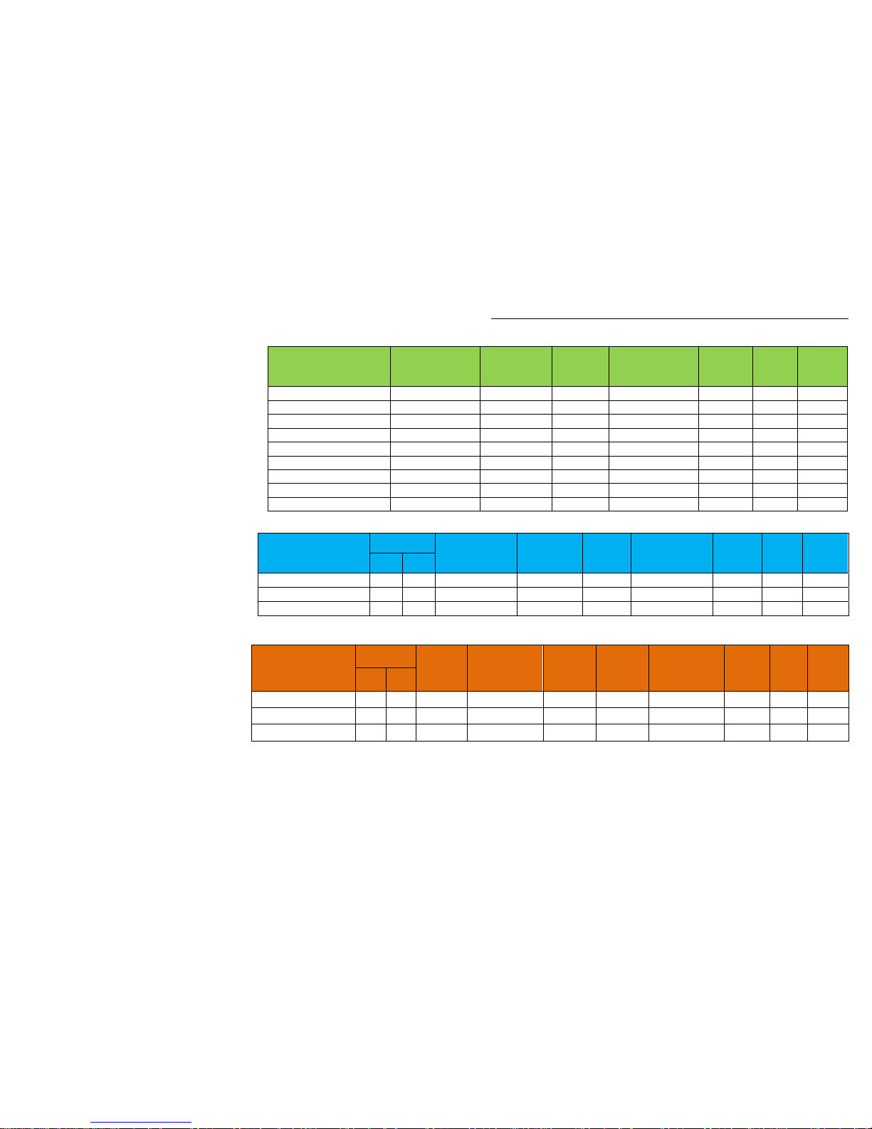
Acoustic Data
–
RAS Indoor Units
Page 5 of 78
RAS Indoor Units
Model
High
dB(A)
Med
dB(A)
Low
dB(A)
RAS-107SKV-E5
40 35 30
RAS-137SKV-E5
40 34 28
RAS-167SKV-E5
45 40 31
RAS-B10N3KVP-E 43 35 27
RAS-B13N3KVP-E 43 35 27
RAS-B16N3KVP-E
45 38 29
RAS-B10UFV-E
39 32 26
RAS-B13UFV-E
40 33 27
RAS-B18UFV-E 46 40 34
RAS-B10N3KV2-E
39 33 26
RAS-B13N3KV2-E
40 33 26
RAS-B16N3KV2-E
45 40 30
RAS-M10SMUV-E
37 33 30
RAS-M13SMUV-E 38 34 30
RAS-M16SMUV-E 40 37 31
The indoor unit is equipped with an automatic restart facility that allows the unit to restart, at the last set operating conditions, after a power
failure. The operation will resume without warning three minutes after power is restored.
This feature is not set up when these systems are shipped from the factory, therefore it will need to be activated by the installing company.
Generally the process is the same for all RAS products since approx 2001 and is as follows:
To initiate auto restart:
1. Turn the power on. Green On/Off light will flash.
2. Set the system to operate using the remote controller. Green On/Off light will be on constantly.
3. Press and hold down the temporary button for three seconds.
4. The indoor unit will bleep three times to acknowledge set up. In most cases the green light changes to orange.
5. The system will continue to operate during this set up.
6. After set up the system may be stopped using the remote controller.
To cancel auto restart:
1. The system is operating. Green On/Off light will be on constantly.
2. Stop the system operating using the remote controller. Green On/Off light will extinguish.
3. Press and hold down the temporary button for three seconds.
4. The indoor unit will bleep three times to acknowledge cancellation.
5. The system will have stopped operating.
This feature cannot be set if the timer is in operation.
The louver will not swing, if it was previously set, when the system auto restarts.
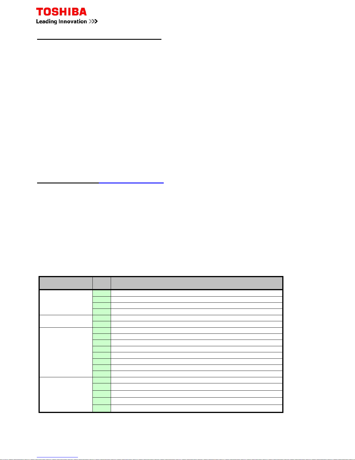
Fault Codes – RAS “N” Series
Do Not turn off the power supply before reading the fault codes, doing so will clear the diagnostic memory. Caution
must be taken when removing the access covers as high voltages are present.
Fault codes are displayed through the LEDs flashing at 5 times per second. Note, the green LED will flash once per
second when the system is initially powered.
More specific codes may be obtained, while in the fault mode through the wireless controller
1. Press CHK to enter service mode
2. Navigate through TIMER buttons until all LEDs flash, accompanied by the internal buzzer – compare the
displayed code with the table below
3. Press CLR button to clear the existing fault code (controller displays 7F)
4. Press ON/OFF button to exit service mode.
Initial
code/display
Code Description
01
0C
TA sensor open or short circuit
0d
TC sensor open or short circuit
11
Indoor fan motor problem
12
Indoor PCB problem
01
04
Indoor to outdoor communication (includes compressor thermostat)
05
Indoor to outdoor communication
02
14
Inverter low voltage or short circuit protection
16
Compressor position circuit
17
Compressor current detected during off-cycle
18
TE or TS sensor open or short circuit
19
Td sensor open or short circuit
1A
Outdoor fan motor problem
1b
TE sensor fault
1C
Compressor drive circuit
03
07
Indoor to outdoor communication (includes compressor thermostat)
08
Indoor heat exchanger changes temperature – but in wrong direction
1d
Compressor locked rotor current protection
1E
Compressor - high discharge temperature
1F
Compressor current remains too high – after current release
RAS – Auto Restart Function
Page 6 of 78
Page 7 of 78
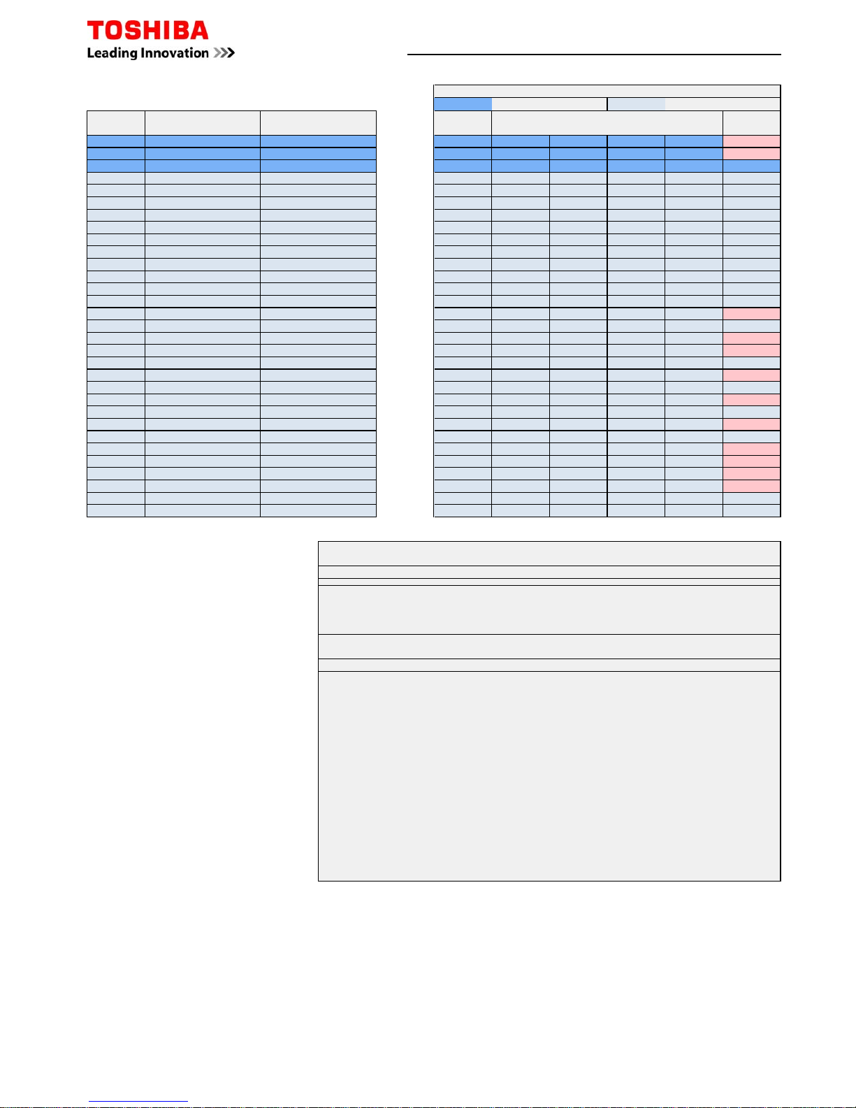
Mechanical Specifications - DI / SDI R410A Single Splits
Model
Pipe Sizes
Min/Max
Pipe Sep
(m)
Max
Height
Separation
Pre-
charge
(m)
Add
Charge
(g/m)
Base
Charge
(kg)
Dimensions
(mm)
Weight
(kg)
Liquid Suction
Commercial Range
RAV-SM564ATP-E
1/4 1/2
5/30
30
20
20 1.0 550x780x290 40
RAV-SM804ATP-E
3/8 5/8
40 1.7 550x780x290 44
RAV-SM1104ATP-E
5/50
30
40 2.8 890x900x320 68
RAV-SM1404ATP-E
40 2.8 890x900x320 68
RAV-SM1603AT-E
40 3.1 1340x900x320 99
RAV-SM2244AT8-E
1/2 1 1/8
7.5/70 80 5.9 1540x900x320 134
RAV-SM2804AT8-E
RAV-SP404ATP-E
1/4 1/2
5/30
20
20 1.0 550x780x290 40
RAV-SP564ATP-E
5/50
20 1.4 550x780x290 44
RAV-SP804ATP-E
3/8 5/8
30
40 2.1 890x900x320 63
RAV-SP1104AT-E
3/75
40 3.1 1340x900x320 93
RAV-SP1404AT-E
40 3.1 1340x900x320 93
RAV-SP1104AT8-E
3/75
40 3.1 1340x900x320 95
RAV-SP1404AT8-E
40 3.1 1340x900x320 95
RAV-SP1604AT8-E
40 3.1 1340x900x320 95
Performance & Electrical Specifications - DI / SDI R410A Single Splits
Model
Capacity kW
Ambient
Range °C
Energy
Rating
Cool/Heat
Phase
Power
To
Soft
Start
Max
Current
Suggested
Fuse Size
Interconnect
Cable
Cool Heat Cool Heat
Commercial Range
RAV-SM564ATP-E
5.00 5.30
46 to -15 15 to -15
A/A
1Ph + N
Outdoor Yes
8.95
16
3Core + Earth
RAV-SM804ATP-E
6.70 7.70 A/A 11.43 16
RAV-SM1104ATP-E
10.00 11.20 A/A 15.18
20
RAV-SM1404ATP-E
12.00 12.80
A/A
21.30 32
RAV-SM1603AT-E
14.00 16.00 B/A 23.90 32
RAV-SM2244AT8-E
20.00 22.40
46 to -20 15 to -20
D/B
3Ph + N
18.00 16
RAV-SM2804AT8-E
23.00 27.00
D/C
20.00 20
RAV-SP404ATP-E
3.60 4.00 43 to -15 15 to -15
A/A
1Ph + N
15.00 10
RAV-SP564ATP-E
5.30 5.60
43 to -15 15 to -20
A/A 13.30
16
RAV-SP804ATP-E
7.10 8.00 A/A 20.30
RAV-SP1104AT-E
10.00 11.20 A/A 20.50
RAV-SP1404AT-E
12.50 14.00 A/A 20.50 25
RAV-SP1104AT8-E
10.00 11.20
46 to -15 15 to -20
A/A
3Ph + N
14.70 10
RAV-SP1404AT8-E
12.50 14.00 A/A 14.70
16
RAV-SP1604AT8-E
14.00 16.00 B/A 14.70
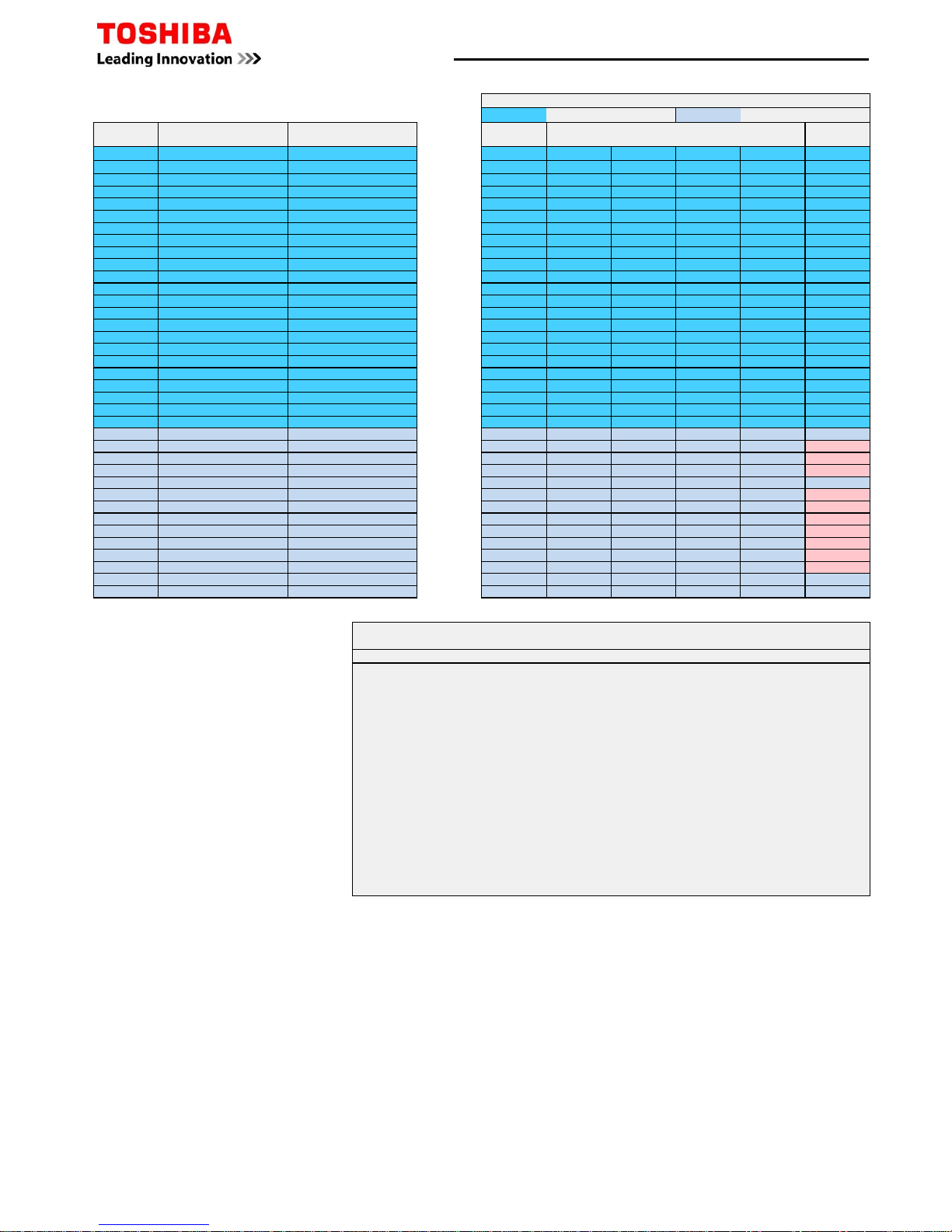
Electrical Specifications - DI / SDI R410A Multi Splits
Page 8 of 78
Model Outdoor Twin Indoor Triple Indoor Quad Indoor Phase
Power
To
Suggested
Fused Size
Inter-
Connecting
Cable
RAV-SM80ATP-E RAV-SM40*T(P)-E
N/A N/A 1Ph-N Outdoor 16 3C+E
RAV-SM1104ATP-E RAV-SM56*T(P)-E N/A N/A
1Ph-N Outdoor 20 3C+E
RAV-SM1404ATP-E RAV-SM80*T(P)-E
N/A N/A 1Ph-N Outdoor 32 3C+E
RAV-SM1603AT-E RAV-SM80*T(P)-E RAV-SM56*T(P)-E
N/A 1Ph-N Outdoor 32 3C+E
RAV-SM2244AT8-E RAV-SM110*T(P)-E RAV-SM80*T(P)-E RAV-SM56*T(P)-E
3Ph-N Outdoor 16 3C+E
RAV-SM2244AT8-E RAV-SM110*T(P)-E RAV-SM80*T(P)-E RAV-SM56*T(P)-E
3Ph-N Outdoor 16 3C+E
RAV-SM2804AT8-E RAV-SM140*T(P)-E RAV-SM80*T(P)-E RAV-SM80*T(P)-E
3Ph-N Outdoor 20 3C+E
RAV-SM2804AT8-E RAV-SM140*T(P)-E RAV-SM80*T(P)-E RAV-SM80*T(P)-E
3Ph-N Outdoor 20 3C+E
RAV-SP804ATP-E RAV-SM40*T(P)-E
N/A N/A 1Ph-N Outdoor 16 3C+E
RAV-SP1104AT-E RAV-SM56*T(P)-E N/A N/A
1Ph-N Outdoor 16 3C+E
RAV-SP1104AT8-E RAV-SM56*T(P)-E
N/A N/A 3Ph-N Outdoor 10 3C+E
RAV-SP1404AT-E RAV-SM80*T(P)-E
N/A N/A 1Ph-N Outdoor 25 3C+E
RAV-SP1404AT8-E RAV-SM80*T(P)-E N/A N/A
3Ph-N Outdoor 16 3C+E
RAV-SP1604AT8-E RAV-SM80*T(P)-E RAV-SM56*T(P)-E
N/A 3Ph-N Outdoor 16 3C+E
Acoustic Data – DI/SDI Indoor/Outdoor Units
Model Indoor
High
dB(A)
Med
dB(A)
Low
dB(A)
Model Indoor
High
dB(A)
Med
dB(A)
Low
dB(A)
RAV-SM562KRT-E
54 51 48
RAV-SM566BT-E
33 29 25
RAV-SM806KRT-E
60 56 51
RAV-SM806BT-E
34 30 26
RAV-SM564UTP-E
32 29 28
RAV-SM1106BT-E
40 36 33
RAV-SM804UTP-E
35 31 28
RAV-SM1406BT-E
40 36 33
RAV-SM1104UTP-E
58 53 48
RAV-SM1606BT-E
40 36 33
RAV-SM1404UTP-E
44 38 34
RAV-SM567CTP-E
37 35 28
RAV-SM1604UTP-E
45 40 36
RAV-SM807CTP-E
41 36 29
RAV-SM404MUT-E
55 51 46
RAV-SM1107CTP-E
44 38 32
RAV-SM564MUT-E
55 51 46
RAV-SM1407CTP-E
46 41 35
RAV-SM404SDT-E
39 36 33
RAV-SM1607CTP-E
46 41 35
RAV-SM564SDT-E
45 40 36
RAV-SM2242DT-E
54 - -
RAV-SM2802DT-E
55 - -
Model Outdoor
Cooling
dB(A)
Heating
dB(A)
Model Outdoor
Cooling
dB(A)
Heating
dB(A)
RAV-SM564ATP-E
46 48
RAV-SP404ATP-E
45 47
RAV-SM804ATP-E
48 52
RAV-SP564ATP-E
47 48
RAV-SM1104ATP-E
53 54
RAV-SP804ATP-E
48 49
RAV-SM1404ATP-E
54 55
RAV-SP1104AT-E
49 50
RAV-SM1603AT-E
51 53
RAV-SP1404AT-E
51 52
RAV-SM2244AT8-E
56 57
RAV-SP1104AT8-E
49 50
RAV-SM2804AT8-E
57 58
RAV-SP1404AT8-E
51 52
RAV-SP1604AT8-E
51 53
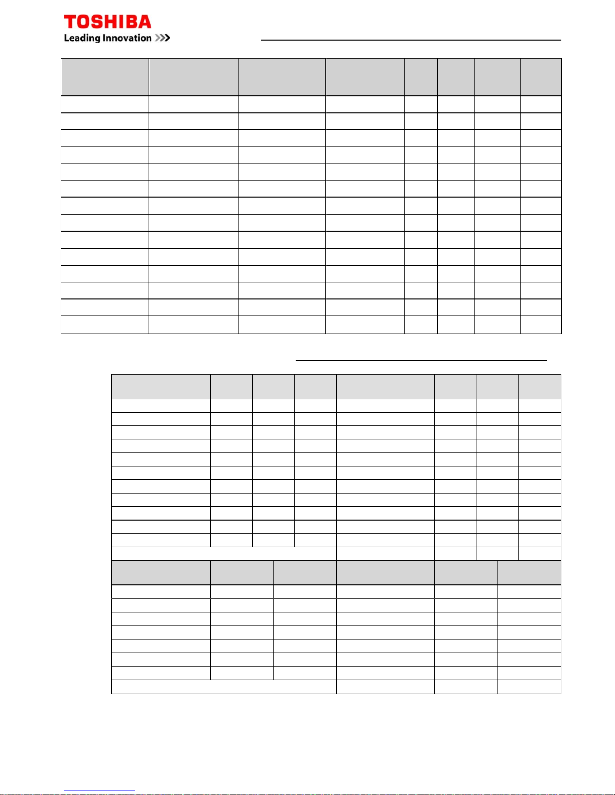
Page 9 of 78
Mechanical & Electrical Data - Air-to-Air Heat Exchangers
Model
(Standard)
Power
Consumption
Low/High (W)
(L/H) Air
Volume
(m³/hr)
Static
Pressure
(Pa)
Dimensions Weight
(kg)
Duct
(mm)
1-ph+n
Fuse
Size
VN-M150HE 42 - 78 110 - 150 47 -102 900x900x290 36 100 3
VN-M250HE 52 - 138 155 - 250 28 - 98 900x900x290 36 150 3
VN-M350HE 82 - 182 210 - 350 65 -125 900x900x290 38 150 3
VN-M500HE 128 - 238 390 - 500 62 -150 1140x1140x350 53 200 3
VN-M650HE 178 - 290 520 - 650 61 -107 1140x1140x350 53 200 5
VN-M800HE 286 - 383 700 - 800 76 -158 1189x1189x400 70 250 5
VN-M1000HE 353 - 569 755 - 1000 84 -150 1189x1189x400 70 250 5
VN-M1500HE 570 - 786 1200 - 1500 112 -156 1189x1189x810 143 250 13
VN-M2000HE 702 - 1154 1400 - 2000 110 -143 1189x1189x810 143 250 13
Model
(DX Coil)
Capacity
Power
Consumption
Low/High (W
)
(L/H) Air
Volume
(m³/hr)
Static
Pressure
(Pa)
Dimensions Weight
(kg)
Duct
(mm)
1ph+n
Fuse
Size
Cool Heat
MMD-VN502HEXE 4.10 5.53
235 - 300 440 - 500 115 - 120 430x1140x1690 84 200 3
MMD-VN802HEXE 6.56 8.61 335 - 505 640 - 800 105 - 120 430x1189x1739 100 250 3
MMD-VN1002HEXE 8.25 10.90 485 - 550 820 - 950 105 - 135 430x1189x1739 101 250 3
Model
(DX Coil & Humidifier)
Capacity
Humidifier
(Kg/hr)
Power
Consumption
Low/High (W
)
(L/H) Air
Volume
(m³/hr)
Static
Pressure
(Pa)
Dimensions
Weight
(kg)
Duct
(mm)
1ph+n
Fuse
Size
Cool Heat
MMD-VNK502HEXE 4.10 5.53
3.0 240 - 305 440 - 500 85 - 95 430x1140x1690 91 200 3
MMD-VNK802HEXE 6.56 8.61 5.0 350 - 530 640 - 800 85 - 105 430x1189x1739
111 250 3
MMD-VNK1002HEXE 8.25 10.90 6.0 520 - 575 820 - 950 90 - 115 430x1189x1739
112 250 5
H x W* x D
H x W* x D
H x W* x D
* Width dimension excludes 200mm electrical box
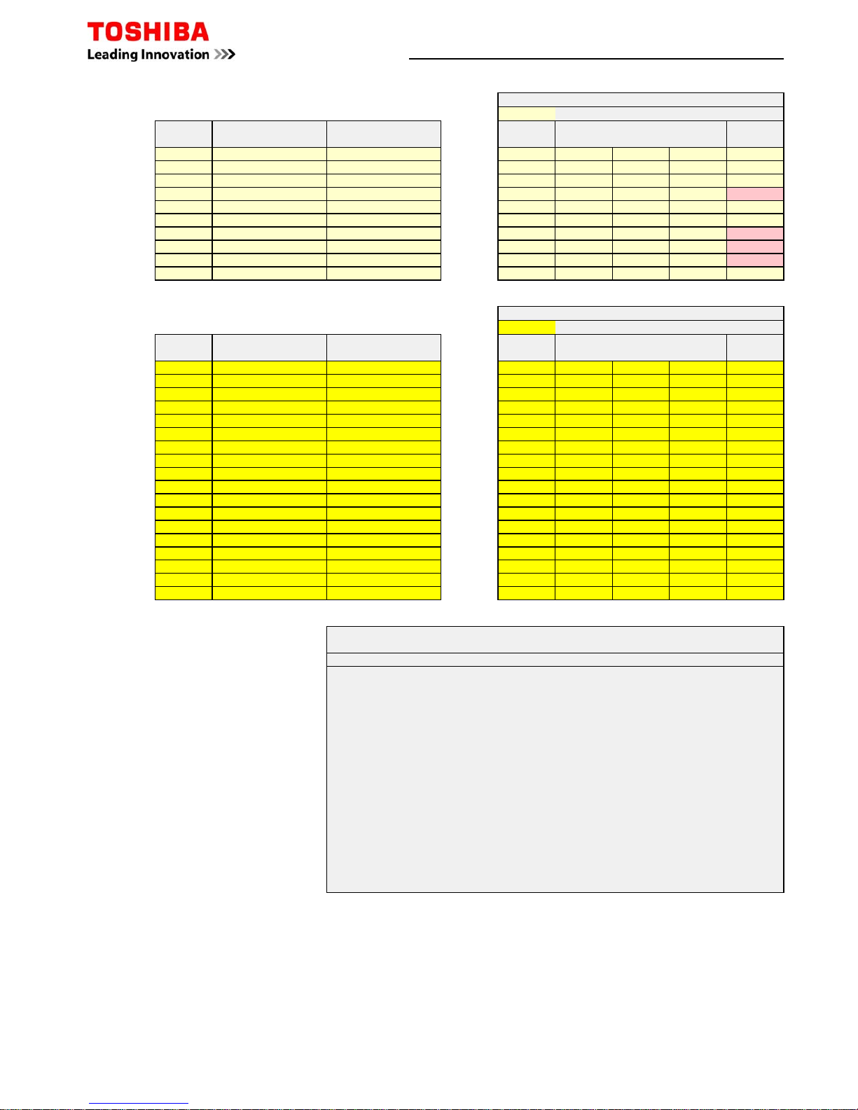
Digital/Super Digital R410A Replacement Technology Refrigerant Pipe Sizing
Length Pre-charged Length Pre-charged Length Pre-charged Length Pre-charged Length Pre-charged
m m m m m m m m m m
SP40430203020302020102010
SP45430203020302020102010
SP5645020502020102010
DI Series 3
SM5635020502020102010
Length Pre-charged Length Pre-charged Length Pre-charged Length Pre-charged Length Pre-charged Length Pre-charged Length Pre-charged
m m m m m m m m m m m m m m
SP80430203020503050305030
SP11047530753025152515
SP14047530753025152515
SM804
202020203020302030
20
SM1104
50305030251525
15
SM1404
50305030251525
15
SM1604
50305030251525
15
Length Pre-charged Length Pre-charged Length Pre-charged Length Pre-charged
m m m m m m m m
SM2244
70307030502050
20
SM2804
70307030502050
20
Performance capacity is reduced due to the effect of gas pipe size being smaller than standard connection
Normal Pipe Sizes
Not Compatible
5/8 - 15.9 (1-size larger) 1/2 - 12.7 (STD) 5/8 - 15.9 (1-size larger)
1/4 - 6.4 (STD) 3/8 - 9.5 (1-size large)
3/8 - 9.5 (1-size smaller) 1/2 - 12.7 (STD)
1/2 - 12.7 (1-size smaller) 5/8 - 15.9 (STD) 1/2 - 12.7 (1-size smaller)
Maximum Pipe Distance
SDI Series 4
1/4 - 6.4 (1-size smaller) 3/8 - 9.5 (STD)
5/8 - 15.9 (STD) 3/4 - 19.1 (1-size larger) 5/8 - 15.9 (STD) 3/4 - 19.1 (1-size larger)
1/2 - 12.7 (1-size larger)
7/8 - 22.2 (1-size smaller) 1 1/8 - 28.6 (STD) 7/8 - 22.2 (1-size smaller) 1 1/8 - 28.6 (STD)
Maximum Pipe Distance
SDI Series 4
DI Series 4
Liquid Pipe Size inch" or mm 1/2 - 12.7 (STD) 5/8 - 15.9 (1-size larger)
SDI Series 4
Gas Pipe Size inch" or mm
Liquid Pipe Size inch" or mm
Liquid Pipe Size inch" or mm
Gas Pipe Size inch" or mm
Maximum Pipe Distance
Gas Pipe Size inch" or mm
Applicable Refrigerants
Existing Plant
R22
R407C
R417A
R404A
R134a
R12
Page 10 of 78
Digital / Super Digital Inverter Multi Split System Combinations
Page 11 of 78
Twin Split Systems
1 x Outdoor Unit
2 x Indoor Units
RAV-SM804ATP-E
RAV-SP804ATP-E
RA V - SM 4 04M UT -E
RA V - SM 4 04SDT -E
RA V - SM 4 06B T -E
RAV-SM1104ATP-E
RAV-SP1104AT-E
RAV-SP1104AT8-E
RA V - SM5 6 4 U T P-E
RA V - SM5 6 4 M U T -E
RA V - SM5 6 7 C T P-E
RA V - SM5 6 6 B T - E
RA V - SM5 6 4 S D T -E
RA V - SM5 6 6 K R T -E
RAV-SM1404ATP-E
RAV-SP1404AT-E
RAV-SP1404AT8-E
RAV-SM804UTP-E
RAV-SM807CTP-E
RAV-SM806BT-E
RAV-SM806KRT-E
RAV-SM1603AT-E
RAV-SP1604AT8-E
RA V - SM8 0 4 U T P-E
RA V - SM8 0 7 C T P-E
RA V - SM8 0 6 B T - E
RA V - SM8 0 6 K R T -E
RAV-SM2244AT8-E
RAV-SM1107CTP-E
RAV-SM1104UTP-E
RAV-SM1106BT-E
RAV-SM2804AT8-E
RAV-SM1407CTP-E
RAV-SM1404UTP-E
RAV-SM1406BT-E
Triple Split Systems
1 x Outdoor Unit
3 x Indoor Units
RAV-SM1603AT-E
RAV-SP1604AT8-E
RA V - SM 5 6 4 U T P- E
RA V - SM 5 6 4 MU T -E
RA V - SM 5 6 7 CT P- E
RA V - SM 5 6 6 B T -E
RA V - SM 5 6 4 SD T -E
RA V - SM 5 6 6 K R T -E
RAV-SM2244AT8-E
RA V - SM 8 0 4 U T P- E
RA V - SM 8 0 4 B T -E
RA V - SM 8 0 7 CT P- E
RA V - SM 8 0 6 K R T -E
RAV-SM2804AT8-E
RA V - SM 8 0 4 U T P- E
RA V - SM 8 0 6 B T -E
RA V - SM 8 0 7 CT P- E
RA V - SM 8 0 6 K R T -E
Quad Split Systems
1 x Outdoor Unit
4 x
Indoor Units
RAV-SM2244AT8-E
RA V - SM 5 6 4 U T P- E
RA V - SM 5 6 4 MU T -E
RA V - SM 5 6 7 CT P- E
RA V - SM 5 6 6 B T -E
RA V - SM 5 6 4 SD T -E
RA V - SM 5 6 6 K R T -E
RAV-SM2804AT8-E
RA V - SM 8 0 4 U T P- E
RA V - SM 8 0 7 CT P- E
RA V - SM 8 0 6 B T -E
RA V - SM 8 0 6 K R T -E
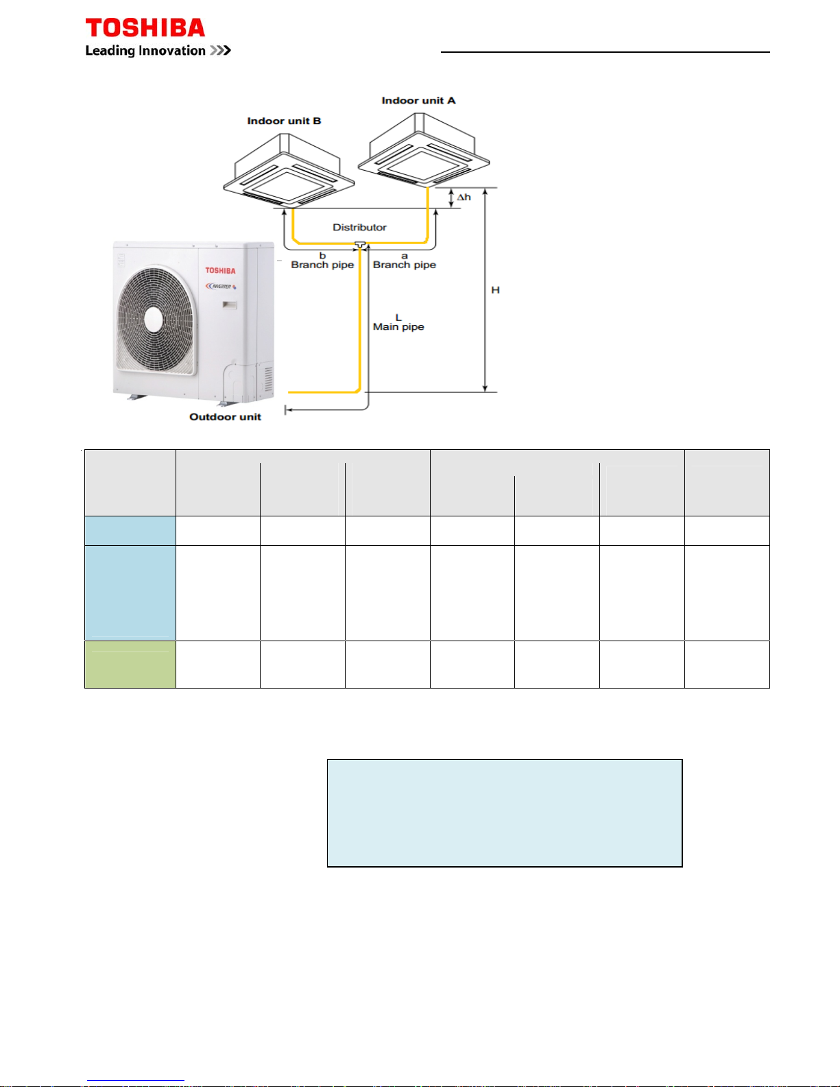
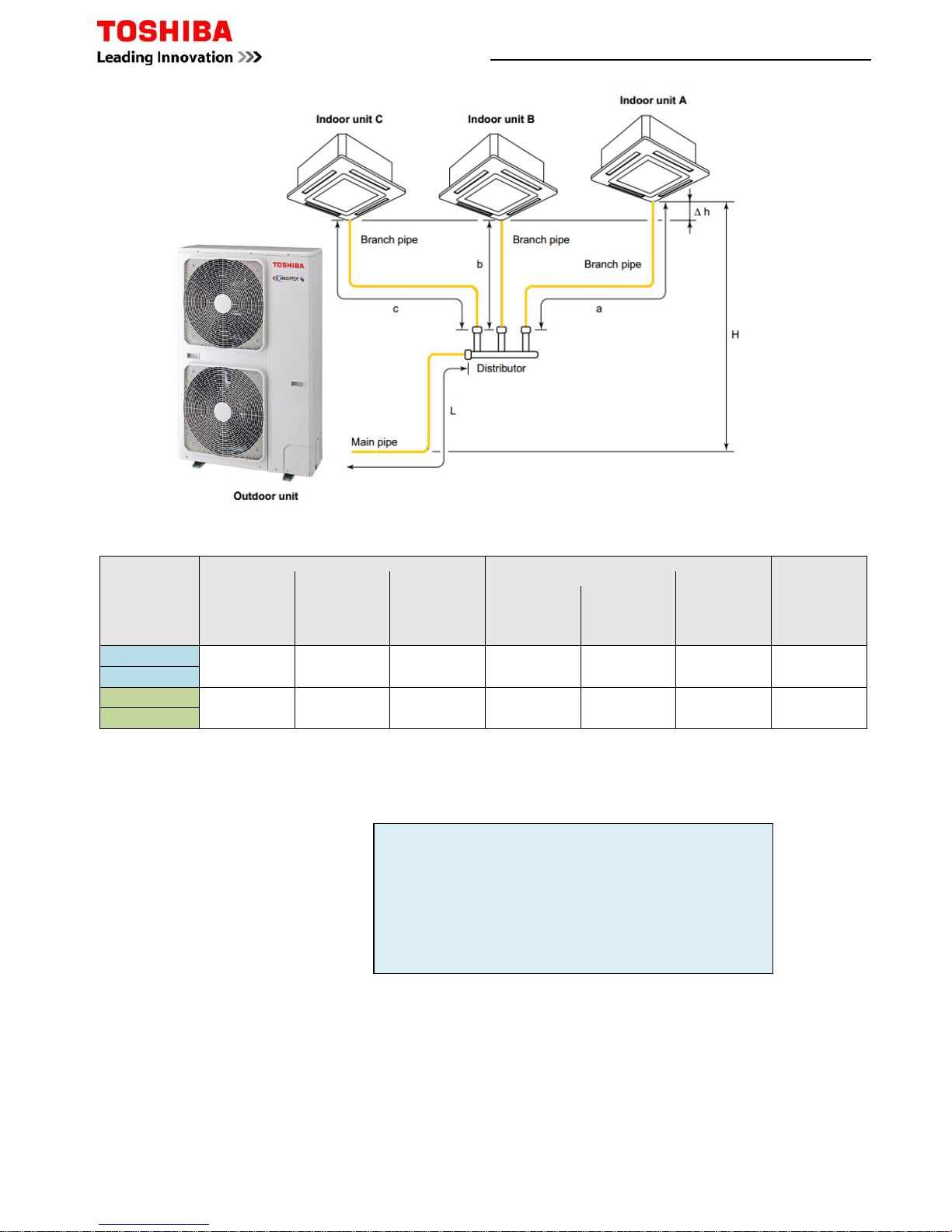
Pipe Specifications
*
Total length of pipe between furthest indoor and outdoor unit.
†
Maximum distance of Branch pipe from main pipe distributor to furthest indoor unit.
‡
Maximum subtractive distance between pipe branches. Example: -
Example 1
Installed length main pipe L to distributor=38m
Installed length branch a=12m
Installed length branch b=10m
Example 2
Installed length main pipe L to distributor=40m
Installed length branch a=14m
Installed length branch b=2m
Example 1
Total pipe length L + a 38 + 12= 50m
Subtractive pipe length a – b 12 - 10= 2m
Example 2
Total pipe length L + a 40 + 14= 64m
Subtractive pipe length a – b 14 - 2= 12m
Digital / Super Digital Inverter Twin Splits
Model
(RAV-)
Allowable Piping Length (m)
Height Difference
(m)
Number of
Bent Portions
Maximum
or Less
*Total Length
(L+a or L+b)
Maximum
†Branch Piping
a or b to
Furthest Indoor
Maximum
‡Subtractive
Piping Length
a-b or b-a
Maximum
Indoor Unit
-
Outdoor Unit (H)
Indoor Unit
Height
Difference (Δh)
Maximum
Outdoor Unit
Higher
Maximum
Indoor Unit
Higher
Maximum
SM804ATP-E 30 10 5 30 30 0.5 10
SM1104ATP-E
SM1404ATP-E
SM1603AT-E
SP804ATP-E
SP1104AT(8)-E
SP1404AT(8)-E
SP1604AT8-E
50 15 10 30 30 0.5 10
SM2244AT8-E
SM2804AT8-E
70 20 10 30 30 0.5 10
Page 12 of 78
Example 3
Installed length main pipe L to distributor=50m
Installed length branch a=12m
Installed length branch b=10m
Example 4
Installed length main pipe L to distributor=60m
Installed length branch a=14m
Installed length branch b=2m
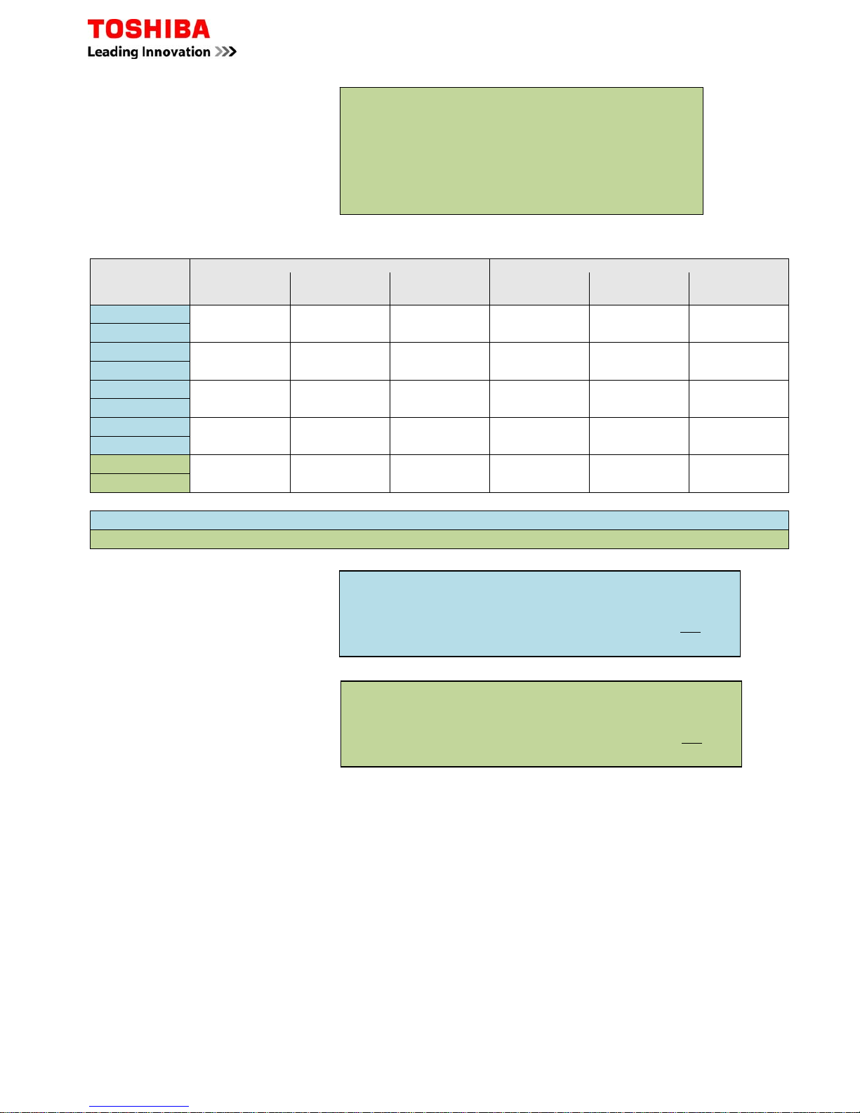
Additional Charge
Example 1
Installed length main pipe L to distributor=38m
Installed length branch a=12m
Installed length branch b=10m
Model
(RAV-)
Main Pipes Branch Pipes
Sizes (“)
Gas/Liquid
Pre-charge (m)
Add Amount
(kg/m) – [ ]
Sizes (“)
Gas/Liquid
Pre-charge (m)
Add Amount
(kg/m) – [ ß ]
SM804ATP-E
5/8 - 3/8 18 0.040 1/2 - 1/4 2 0.020
SP804ATP-E
SM1104ATP-E
5/8 - 3/8 18 0.040 1/2 - 1/4 2 0.020
SP1104AT(8)-E
SM1404ATP-E
5/8 - 3/8 18 0.040 5/8 - 3/8 2 0.040
SP1404AT(8)-E
SM1603AT-E
5/8 - 3/8 28 0.040 5/8 - 3/8 2 0.040
SP1604AT8-E
SM2244AT8-E
1 1/8 - 1/2 28 0.080 5/8 - 3/8 4 0.040
SM2804AT8-E
Gas calculation - [Main pipe] (L-18) x + [Branch Pipe] (a+b - 4) x ß = additional charge
Gas calculation - [Main pipe] (L-28) x + [Branch Pipe] (a+b - 4) x ß= additional charge
Example 1 using SM1104ATP-E
Total pipe length L - 18 x
38 - 18 =20 x 0.040= 0.80 +
Branch pipe length a + b x ß 12 + 10 - 4 =18 x 0.020= 0.36
Add Amount 1.16 kg
Example 3
Total pipe length L + a 50 + 12= 62m
Subtractive pipe length a – b 12 - 10= 2m
Example 4
Total pipe length L + a 60 + 14= 74m
Subtractive pipe length a – b 14 - 2= 12m
Example 1 using SM2804AT8-E
Total pipe length L - 28 x
38 - 28 =10 x 0.080= 0.80 +
Branch pipe length a + b x ß 12 + 10 - 4 =18 x 0.040= 0.72
Add Amount 1.52 kg
Page 13 of 78
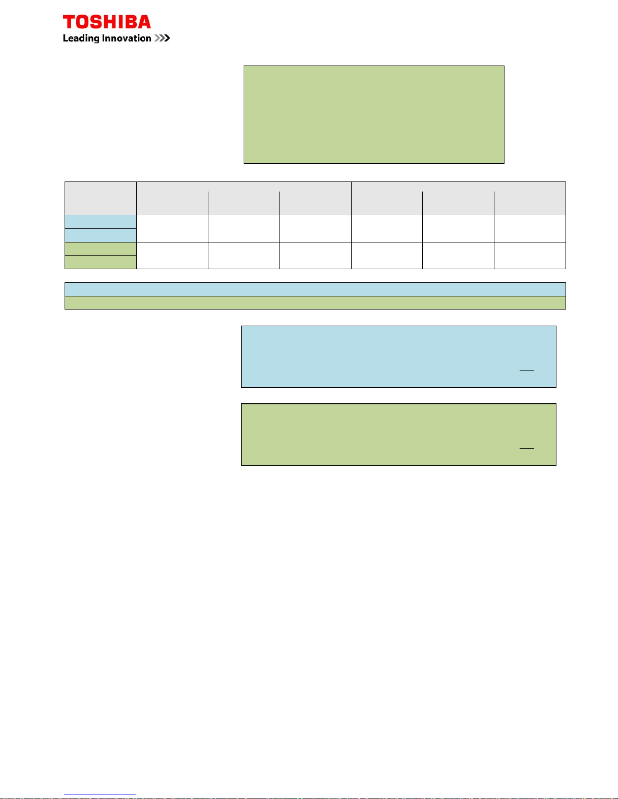
Factor
Factor
Pipe Specifications
Model (RAV-)
Allowable Piping Lengths (m) Height Difference (m)
Number of
Bent portions
Maximum
or Less
*
Total Length
La + Lb
La + Lc
Maximum
†
Branch Piping
La, Lb or Lc to
Furthest Indoor
Maximum
‡
Subtractive
Piping Length
Lb - La
Lb - Lc
Maximum
Indoor Unit - Outdoor Unit (H)
Indoor Unit
Height
Difference (∆h)
Maximum
Outdoor Unit
Higher
Maximum
Indoor Unit
Higher
Maximum
SM1603AT-E
50 15 10 30 30 0.5 10
SP1604AT8-E
SM2244AT8-E
70 20 10 30 30 0.5 10
SM2804AT8-E
*
Total length of pipe between furthest indoor and outdoor unit.
†
Maximum distance of Branch pipe from main pipe distributor to furthest indoor unit.
‡
Maximum subtractive distance between pipe branches. Example: -
Example 1
Installed length main pipe L to distributor=38m
Installed length branch a=12m
Installed length branch b=10m
Installed length branch c=12m
Example 2
Installed length main pipe L to distributor=40m
Installed length branch a=15m
Installed length branch b=4m
Installed length branch c=12m
Example 1
Total pipe length L + a 38 + 12= 50m
Subtractive pipe length a – b 12 - 10= 2m
Subtractive pipe length c – b 12 - 10= 2m
Example 2
Total pipe length L + a 40 + 15= 55m
Subtractive pipe length a – b 15 - 4= 11m
Subtractive pipe length c – b 12 - 4= 8m
Digital / Super Digital Inverter Triple Splits
Page 14 of 78
Example 3
Installed length main pipe L to distributor=40m
Installed length branch a=12m
Installed length branch b=12m
Installed length branch c=10m
Example 4
Installed length main pipe L to distributor=50m
Installed length branch a=20m
Installed length branch b=3m
Installed length branch c=5m
Additional Charge
Model (RAV-)
Main Pipes Branch Pipes
Sizes (“)
Gas/Liquid
Pre-charge (m)
Add Amount
(kg/m) – [ ]
Sizes (“)
Gas/Liquid
Pre-charge (m)
Add Amount
(g/m) – [ ß ]
SM1603AT-E
5/8 – 3/8 28 0.040 5/8 – 3/8
6 0.040
SP1604AT8-E
SM2244AT8-E
1 1/8 – 1/2 28 0.080 5/8 – 3/8 6 0.040
SM2804AT8-E
Gas calculation - [Main pipe] (L-28) x + [Branch Pipe] (a+b+c - 6) x ß = additional charge
Gas calculation - [Main pipe] (L-28) x + [Branch Pipe] (a+b+c - 6) x ß= additional charge
Example 1
Installed length main pipe L to distributor=38m
Installed length branch a=12m
Installed length branch b=10m
Installed length branch c=12m
Example 3
Total pipe length L + a 40 + 12= 52m
Subtractive pipe length a – b 12 - 12= 0m
Subtractive pipe length c – b 12 - 10= 2m
Example 4
Total pipe length L + a 50 + 20= 70m
Subtractive pipe length a – b 20 - 3= 15m
Subtractive pipe length c – b 5 - 3= 2m
Example 1 above using SM1603AT-E
Total pipe length L - 28 x
38 - 28 =10 x 0.040= 0.40 +
Branch pipe length a + b + c x ß 12+10+ 12- 6 =28 x 0.040= 1.12
Add Amount 1.52 kg
Example 1 above using SM2804AT8-E
Total pipe length L - 28 x
38 - 18 =20 x 0.080= 0.80 +
Branch pipe length a + b + c x ß 12+10+ 12- 6 =28 x 0.040= 1.12
Add Amount 1.92 kg
Page 15 of 78
Factor
Factor
Example 1
Total pipe length L + b + c 20 + 10 + 5= 35m
Branch length b + d 10 + 5= 15m
Branch length a + e 10 + 5= 15m
Branch length a + f 10 + 5= 15m
Subtractive pipe length c+b - d+b 5+10 - 5+10= 0m
Subtractive pipe length c+b - e+a 5+10 - 5+10= 0m
Subtractive pipe length c+b - f+a 5+10 - 5+10= 0m
Subtractive pipe length d+b - e+a 5+10 - 5+10= 0m
Subtractive pipe length d+b - f+a 5+10 - 5+10= 0m
Subtractive pipe length e+a - f+a 5+10 - 5+10= 0m
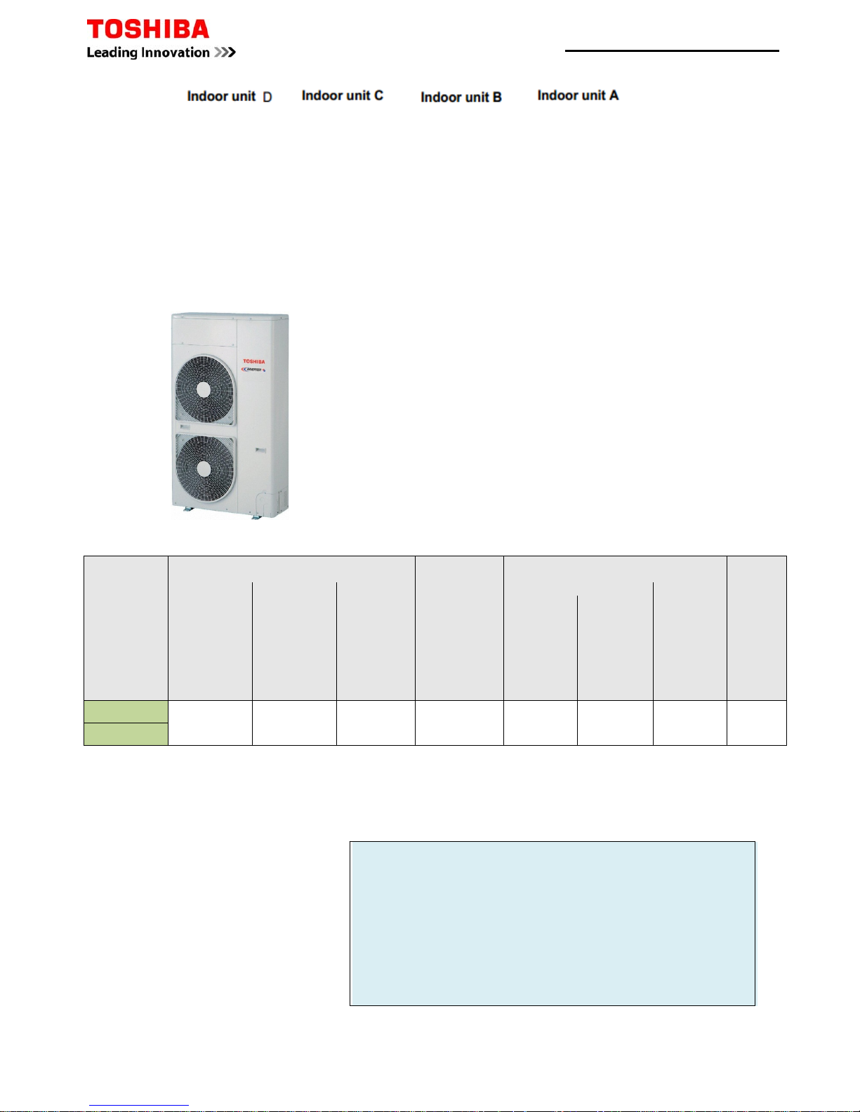
Pipe Specifications
Model (RAV-)
Allowable Piping Lengths (m)
Height Difference (m)
Number of
Bent
portions
Maximum
or Less
*
Total Length
(L+b+c) or
(L+b+d) or
(L+a+e) or
(L+a+f)
Maximum
†
Branch Piping
c, d, e & f to
Furthest Indoor
Maximum
¥Branch Piping
b+c
b+d
a+e
a+f
Maximum
‡
Subtractive
Branch Piping
(c+b) - (d+b)
(c+b) - (e+a)
(c+b) - (f+a)
(d+b) - (e+a)
(d+b) - (f+a)
(e+a) - (f+a)
Maximum
Outdoor Unit-Indoor Unit(H)
Indoor unit
height
difference
(∆h)
Maximum
Outdoor Unit
higher
Maximum
Indoor Unit
higher
Maximum
SM2244AT8-E
70 15 20 6 30 30 0.5 10
SM2804AT8-E
*
Total length of pipe between furthest indoor and outdoor unit.
†
Maximum distance of Branch pipe from main pipe distributor to furthest indoor unit.
¥ Maximum pipe distance between Branched pairs
‡
Maximum subtractive distance between pipe branches. Example:
Example 1
Installed length main pipe L to distributor=20m
Installed length branch b=10m
Installed length branch c=5m
Installed length branch d=5m
Installed length branch a=10m
Installed length branch e=5m
Installed length branch f=5m
Digital Inverter Quad Splits
Page 16 of 78
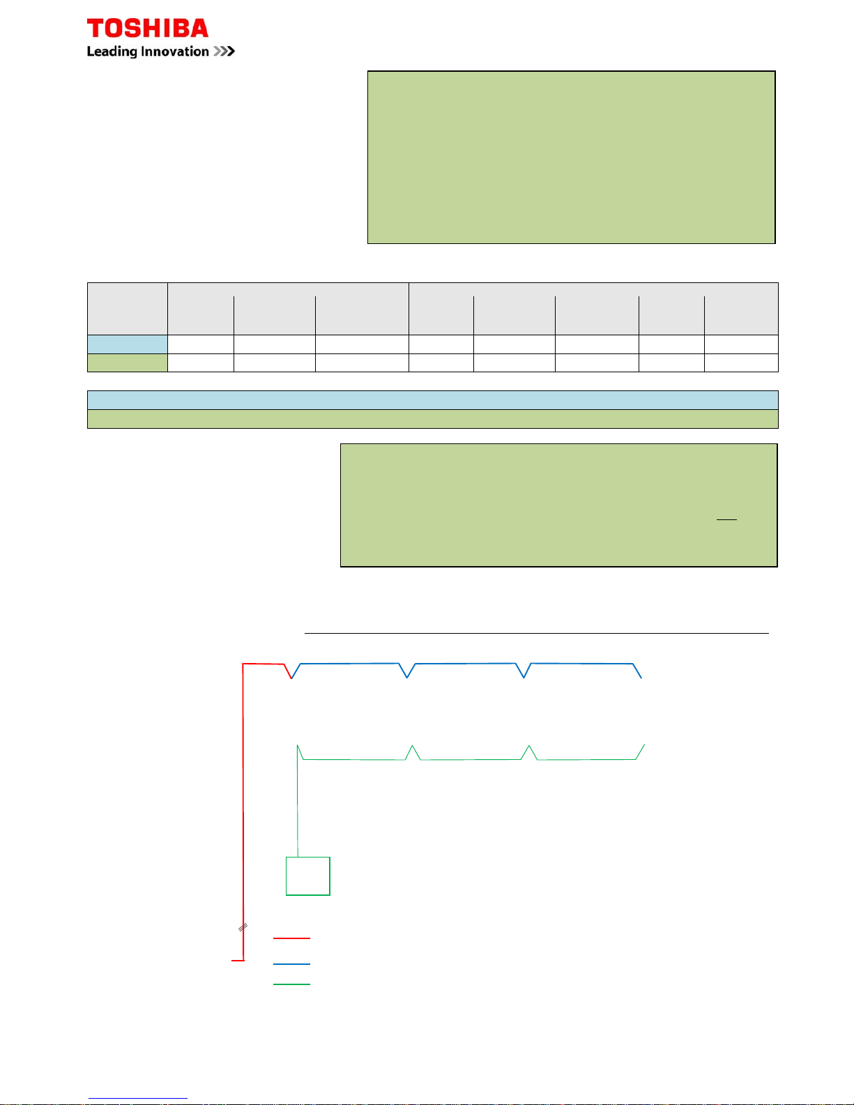
Page 17 of 78
Interconnecting Cables
3 Core+Earth Power connected to terminals
2 Core+Earth Power connected to terminals
2 Core Control connected to terminals A + B
Example 2
Total pipe length L + b + c 50+ 15+ 10 = 75m
Branch length b + c 15+ 10 = 25m
Branch length b + d 15+ 6 = 21m
Branch length a + e 15+ 5 = 20m
Branch length a + f 15+ 10 = 25m
Subtractive pipe length c+b - d+b 10+ 15- 6+ 15 = 4m
Subtractive pipe length c+b - e+a 10+ 15- 5+ 15 = 5m
Subtractive pipe length c+b - f+a 10+ 15- 10+ 15 = 0m
Subtractive pipe length d+b - e+a 6+ 15- 5+ 15 = 1m
Subtractive pipe length d+b - f+a 6+ 15- 10+ 15 = 1m
Subtractive pipe length e+a - f+a 6+ 15- 10+ 15 = 1m
Example 2
Installed length main pipe L to distributor=50m
Installed length branch b=15m
Installed length branch c=10m
Installed length branch d=6m
Installed length branch a=15m
Installed length branch e=5m
Installed length branch f=10m
Additional Charge
Example 1
Installed length main pipe L to distributor=20m
Installed length branch b=10m
Installed length branch c=5m
Installed length branch d=5m
Installed length branch a=10m
Installed length branch e=5m
Installed length branch f=5m
Model
Main Pipes Branch pipes
Sizes (“)
Gas/Liquid
Pre-charge (m) Add amount
(kg/m) – []
Sizes (“)
Gas/Liquid
Pre-charge (m) Add amount
(g/m) – [ß]
Sizes (“)
Gas/Liquid
Add amount
(g/m) – [γ]
SM2244AT8-E 1 1/8 – 1/2 28 0.080 5/8 – 3/8 4 0.040 1/2 – 1/4 0.020
SM2804AT8-E 1 1/8 – 1/2 28 0.080 5/8 – 3/8 4 0.040 5/8 – 3/8 0.040
Gas calculation - [Main pipe] (L-28) x + [Branch Pipe] (a + b - 4) x ß + (c+d+e+f) x
γ
= additional charge
Gas calculation - [Main pipe] (L-28) x + [Branch Pipe] (a + b - 4) x ß + (c+d+e+f) x
γ
= additional charge
Example 1 using SM2804AT8-E
Total pipe length L - 28 x
20 - 28 =-8 x 0.080= -0.64 +
Branch pipe length a + b 4 x ß 10+10- 4 =16 x 0.040= 0.64 +
Branch pipe length c + d + e + f x
γ 5+5+5+5 =20 x 0.040= 0.80
Add Amount 0.80 kg
Configuration same for Twin, Triple & Quad combinations.
A common controller will be used, individual controls is not possible.
Master to Slave power supply.
Indoor Unit B
Indoor Unit CIndoor Unit D
Indoor Unit A
Remote
Controller
Digital / Super Digital Multi Split System Wiring Schematic
Factor
Factor
VRF System Make Up Chart
Model
Reference
MMY
Duty
HP
Cooling
Capacity
kW
Heating
Capacity
kW
Outdoor Unit Combination
Max.
Indoor
Units
0401 0501 0601 0804 1004 1204 1404 1604
Mini SMMS MCY
MAP0401HT
4
12.1
12.516
MAP0501HT 5 14.0 16.0 1 8
MAP0601HT 6 15.5 18.0 1 9
Note:- MAP0401HT, MAP0501HT & MAP601HT are
NOT
Modular
SMMSiHeat Pump MMY
MAP0501HT8-E 5 14.0 16.0 1 1 8
MAP0601HT8-E 6 16.0 18.0 10
MAP0804HT8-E 8 22.4 25.0 1 13
MAP1004HT8-E 10 28.0 31.5 1 16
MAP1204HT8-E 12 33.5 37.5 1 20
MAP1404HT8-E 14 40.0 45.0 1 23
MAP1604HT8-E 16 45.0 50.0 1 27
AP1814HT8-E 18 50.4 56.5 1 1 30
AP2014HT8-E 20 56.0 63.0 2 33
AP2214HT8-E 22 61.5 69.0 1 1 37
AP2414HT8-E 24 68.0 76.5 2 40
AP2614HT8E
26
73.0
81.511
43
AP2814HT8-E 28 78.5 88.0 1 1 47
AP3014HT8-E 30 85.0 95.0 1 1 48
AP3214HT8-E 32 90.0 100.0 2 48
AP3414HT8E
34
96.0
108.0
1248
AP3614HT8-E 36 101.0 113.0 3 48
AP3814HT8E
38
106.5
119.5
111
48
AP4014HT8-E 40 112.0 127.0 2 1 48
AP4214HT8-E 42 118.0 132.0 1 1 1 48
AP4414HT8-E 44 123.5 138.0 1 2 48
AP4614HT8-E 46 130.0 145.0 1 2 48
AP4814HT8-E 48 135.0 150.0 3 48
SMMSiHigh Efficiency Heat Pump MMY
AP1624HT8-E 16 45.0 50.0 2 27
AP2424HT8-E 24 68.0 76.5 3 40
AP2624HT8-E 26 73.0 81.5 2 1 43
AP2824HT8-E 28 78.5 88.0 1 2 47
AP3024HT8-E 30 85.0 95.0 3 48
AP3224HT8-E 32 90.0 100.0 4 48
AP3424HT8-E 34 96.0 108.0 3 1 48
AP3624HT8-E 36 101.0 113.0 2 2 48
AP3824HT8-E 38 106.5 119.5 1 3 48
AP4024HT8-E 40 112.0 126.5 4 48
AP4224HT8-E 42 118.0 132.0 3 1 48
AP4424HT8-E 44 123.5 138.0 2 2 48
AP4624HT8-E 46 130.0 145.0 1 3 48
AP4824HT8-E 48 135.0 150.0 4 48
SHRMiHeat Recovery MMY
Model
Reference
MMY
Duty
HP
Cooling
Capacity
Kw
Heating
Capacity
kW
Outdoor Unit Combination
Max.
Indoor
Units
0804 1004 1204 1404
MAP0804FT8-E 8 22.4 25.0 1 13
MAP1004FT8-E 10 28.0 31.5 1 16
MAP1204FT8-E 12 33.5 37.5 1 20
MAP1404FT8-E 14 40.0 45.0 1 23
AP1614FT8-E 16 45.0 50.0 2 27
AP1814FT8-E 18 50.4 56.5 1 1 30
AP2014FT8-E 20 56.0 63.0 2 33
AP2214FT8-E 22 61.5 69.0 1 1 37
AP2414FT8-E 24 68.0 76.5 1 1 40
AP2614FT8-E 26 73.0 81.5 1 1 43
AP2814FT8-E 28 78.5 88.0 2 47
AP3014FT8-E 30 85.0 95.0 3 48
AP3214FT8-E 32 90.0 100.0 2 1 48
AP3414FT8-E 34 96.0 108.0 2 1 48
AP3614FT8-E 36 101.0 113.0 3 48
AP3814FT8-E 38 106.5 119.5 2 1 48
AP4014FT8-E 40 112.0 127.0 1 2 48
AP4214FT8-E 42 118.0 132.0 3 48
Page 18 of 78

Electrical Data – VRF Outdoor Units
Model (Outdoor) HP Phase
Power
To
Soft
Start
Suggested
Fuse Size
Fuse
Type
Inter-Connecting
Cable
Mini SMMS
MCY-MAP0401HT 4 1Ph-N
Indoor + Outdoor
Y 20 C 2C Screened
MCY-MAP0501HT 5 1Ph-N
Indoor + Outdoor
Y 25 C 2C Screened
MCY-MAP0601HT 6 1Ph-N
Indoor + Outdoor
Y 32 C 2C Screened
SMMS
MMY-MAP0501HT8-E 5 3Ph-N Indoor + Outdoor Y 16 C 2C Screened
MMY-MAP0601HT8-E 6 3Ph-N
Indoor + Outdoor
Y 16
C
2C Screened
SMMS
i
MMY-MAP0804HT8-E 8 3Ph-N
Indoor + Outdoor
Y 16 C 2C Screened
MMY-MAP1004HT8-E 10 3Ph-N Indoor + Outdoor Y 16 C 2C Screened
MMY-MAP1204HT8-E 12 3Ph-N
Indoor + Outdoor
Y 25 C 2C Screened
MMY-MAP1404HT8-E 14 3Ph-N
Indoor + Outdoor
Y 25 C 2C Screened
MMY-MAP1604HT8-E 16 3Ph-N
Indoor + Outdoor
Y 32 C 2C Screened
SHRM
i
MMY-MAP0804FT8-E 8 3Ph-N
Indoor + Outdoor
Y 16 C 2C Screened
MMY-MAP1004FT8-E 10 3Ph-N
Indoor + Outdoor
Y 20 C 2C Screened
MMY-MAP1204FT8-E 12 3Ph-N
Indoor + Outdoor
Y 20 C 2C Screened
MMY-MAP1404FT8-E 14 3Ph-N
Indoor + Outdoor
Y 25 C 2C Screened
VRF Additional Refrigerant Charge Amount
Indoor Unit
Model
Capacity
Code HP
Capacity
Code kW
007 0.8
2.2
009 1
2.8
012 1.25
3.6
015 1.7
4.5
018 2
5.6
024 2.5
7.1
027 3
8.0
030 3.2
9.0
036 4
11.2
048 5
14.0
056 6
16.0
072 8
22.4
096 10
28.0
Capacity Data – VRF Indoor Units
Liquid
SMMS SHRM
Pipe Size
Mini SMMS
SMMS
i
SHRM
i
inch" - mm kg/m kg/m kg/m
1/4 - 6.4 0.025 0.025 0.0325
3/8 - 9.5 0.055 0.055 0.0715
1/2 - 12.7 0.105 0.1365
5/8 - 15.9 0.160 0.2080
3/4 - 19.1 0.250 0.3250
7/8 - 22.2 0.350 0.4550
Additonal Refrigerant Charge Amount
Page 19 of 78
VRF Additional Refrigerant Charge Calculations
Page 20 of 78
Correction
1 2 3 4 Factor kg
4 4 4 -0.8
5 5 5 -0.4
6 6 6 0
5 5 5 0
6 6 6 0
8 8 8 1.5
10 10 10 2.5
12 12 12 3.5
14 14 8 6 0
16 16 8 8 0
18 18 10 8 0
20 20 10 10 3
22 22 8 8 6 0
22 22 12 10 5
24 24 8 8 8 -4
24 24 12 12 7
26 26 10 8 8 -4
28 28 10 10 8 -2
30 30 10 10 10 0
32 32 8 8 8 8 -6
32 32 12 10 10 1
34 34 10 8 8 8 -6
34 34 12 12 10 3
36 36 10 10 8 8 -6
36 36 12 12 12 4
38 38 10 10 10 8 -6
40 40 10 10 10 10 -5
42 42 12 10 10 10 -4
44 44 12 12 10 10 -2
46 46 12 12 12 10 0
48 48 12 12 12 12 2
Refrigerant
Length
0.0250 x =
0.0550 x =
Additional amount of refrigerant =
Refrigerant
Length
0.025 x =
0.055 x =
0.105 x =
0.160 x =
0.250 x =
0.350 x =
Additional amount of refrigerant =
Total System Charge =
Base Charge + Additional Refrigerant Charge + HP Correction Factor
HP
MAP0501HT8-E
MAP0601HT8-E
SMMS
12.5
12.5
Base Charge kg
Trim Charge
Mini SMMS
SMMS
Condenser Combinations
HP
MAP1001HT8-E
AP3001HT8-E
AP3201HT8-E
AP3211HT8-E
kg
kg
MAP0801HT8-E
MCY-MAP0401HT
MCY-MAP0601HT
7.2
7.2
MCY-MAP0501HT
7.2
8.5
8.5
AP4001HT8-E
AP4201HT8-E
AP4401HT8-E
AP4601HT8-E
AP4801HT8-E
AP3401HT8-E
AP3411HT8-E
AP3601HT8-E
AP3611HT8-E
AP3801HT8-E
MAP1201HT8-E
AP1401HT8-E
AP1601HT8-E
AP1801HT8-E
AP2001HT8-E
AP2201HT8-E
AP2211HT8-E
AP2401HT8-E
AP2411HT8-E
AP2601HT8-E
AP2801HT8-E
kg
x
Additional Refrigerant Charge Amount kg/m
Calculation of Additional Refrigerant Charge SMMS
kg
1/4 - 6.4
3/8 - 9.5
Additional Amount of
Calculation of Additional Refrigerant Charge Mini SMMS
Liquid Line Pipe Diameter Ø
50.0
50.0
50.0
50.0
Liquid Line Pipe Diameter Ø
Additional Amount of
1/4 - 6.4 kg
21.0
25.0
25.0
25.0
33.5
25.0
37.5
25.0
37.5
37.5
37.5
50.0
37.5
50.0
3/8 - 9.5 kg
Additional refrigerant
charge amount at site
Note: if a negative result occurs the additonal refrigerant amount is 0 kg
12.5
37.5
50.0
37.5
50.0
50.0
*** No additional refrigerant charge or change to Factory charge is required ***
3/4 - 19.1 kg
1/2 - 12.7 kg
5/8 - 15.9 kg
=
Real Length of Liquid Line m
+
HP Correction Factor kg
7/8 - 22.2 kg
VRF Additional Refrigerant Charge Calculations
Page 21 of 78
Correction
HP1234
Factor kg
5 5 5 0
6 6 6 0
888
1.5
101010
2.5
121212
3.51414148.516161610.518181080202010103222216105242412127.5
262616108.5
282816129.5
3030161411.5
3232161612.5
3434121210
3
3636121212
4
3838161210
6
4040161212
7
4242161412
8
4444161612
10
4646161614
12
4848161616
14
1616880
2424888
-4
26261088
-4
282810108
-2
3030101010
0
32328888-6
343410888-6
3636101088-638381010108-6404010101010-5424212101010-4444412121010-2464612121210
0
4848121212122
Refrigerant
Length
0.025 x =
0.055 x =
0.105 x =
0.160 x =
0.250 x =
0.350 x =
Additional amount of refrigerant =
Total System Charge =
Base Charge + Additional Refrigerant Charge + HP Correction Factor
Trim Charge
SMMS & SMMS
i
SMMS
i
High Efficiency
HP SMMS & SMMS
i
Base Charge kg
MAP0804HT8-E
11.5
MAP1004HT8-E
11.5
MAP1204HT8-E
11.5
MAP0501HT8-E
8.5
Condenser Combinations
MAP0601HT8-E
8.5
AP4814HT8-E
23.0
23.0
23.0
23.0
23.0
23.0
23.0
23.0
34.5
34.5
AP3614HT8-E
AP3814HT8-E
AP4014HT8-E
AP4214HT8-E
AP4414HT8-E
AP4614HT8-E
MAP1404HT8-E
MAP1604HT8-E
11.5
11.5
AP1814HT8-E
AP2014HT8-E
AP2214HT8-E
AP2414HT8-E
AP2614HT8-E
AP2814HT8-E
AP3014HT8-E
AP3214HT8-E
AP3414HT8-E
34.5
23.0
34.5
34.5
34.5
34.5
34.5
34.5
34.5
34.5
46.0
46.0
46.0
46.0
46.0
34.5
46.0
46.0
46.0
46.0
AP3224HT8-E
AP3424HT8-E
AP3624HT8-E
AP3824HT8-E
AP4024HT8-E
AP1624HT8-E
AP2424HT8-E
AP2624HT8-E
AP2824HT8-E
AP3024HT8-E
Liquid Line Pipe Diameter Ø
Additional Amount of
1/4 - 6.4 kg
3/8 - 9.5 kg
AP4224HT8-E
AP4424HT8-E
AP4624HT8-E
AP4824HT8-E
Calculation of Additional Refrigerant Charge SMMSi & High Efficiency
7/8 - 22.2 kg
kg
1/2 - 12.7 kg
5/8 - 15.9 kg
3/4 - 19.1 kg
charge amount at site
Real Length of Liquid Line m
Note: if a negative result occurs the additonal refrigerant amount is 0 kg
*** No additional refrigerant charge or change to Factory charge is required ***
Additional refrigerant
Additional Refrigerant Charge Amount kg/m
=x+
HP Correction Factor kg
VRF Additional Refrigerant Charge Calculations
Correction
HP 1 2 3 Factor kg
8 8 8 2
10 10 10 2.5
12 12 12 3
16 16 8 8 -1.5
18 18 10 8 0
20 20 10 10 2
24 24 8 8 8 -4.5
26 26 10 8 8 -3
28 28 10 10 8 -1.5
30 30 10 10 10 0
Correction
HP 1 2 3 Factor kg
8 8 8 2
10 10 10 3
12 12 12 8
14 14 14 10
16 16 8 8 0
18 18 10 8 1.5
20 20 10 10 3.5
22 22 12 10 7.5
24 24 14 10 8.5
26 26 14 12 11
28 28 14 14 12
30 30 10 10 10 2.5
32 32 12 10 10 5
34 34 14 10 10 6
36 36 12 12 12 8
38 38 14 12 12 9.5
40 40 14 14 12 11
42 42 14 14 14 12.5
Refrigerant
Length
0.0325 x =
0.0715 x =
0.1365 x =
0.2080 x =
0.3250 x =
0.4550 x =
Additional amount of refrigerant =
Total System Charge =
Base Charge + Additional Refrigerant Charge + HP Correction Factor
Trim Charge
SHRM
i
Condenser Combinations
Trim Charge
SHRM
HP SHRM Base Charge kg
MAP0802FT8-E
11.5
Condenser Combinations
HP SHRM
i
Base Charge kg
MAP0804FT8-E
11.0
MAP1004FT8-E
MAP1204FT8-E
MAP1404FT8-E
11.0
AP2214FT8-E
AP2414FT8-E
AP2614FT8-E
AP2814FT8-E
AP3014FT8-E
11.0
11.0
AP1614FT8-E
AP1814FT8-E
AP2014FT8-E
22.0
22.0
22.0
22.0
22.0
22.0
22.0
33.0
33.0
MAP2602HT8-E
34.5
MAP2802HT8-E
34.5
MAP1602HT8-E
23.0
MAP1802HT8-E
23.0
MAP2002HT8-E
23.0
MAP2402HT8-E
34.5
AP4214FT8-E
33.0
33.0
33.0
33.0
33.0
AP3214FT8-E
AP3414FT8-E
AP3614FT8-E
AP3814FT8-E
AP4014FT8-E
MAP1002FT8-E
11.5
MAP1202FT8-E
11.5
1/4 - 6.4 kg
kg
1/2 - 12.7 kg
Calculation of Additional Refrigerant Charge SHRMi
Liquid Line Pipe Diameter Ø
Additional Amount of
MAP3002HT8-E
34.5
*** No additional refrigerant charge or change to Factory charge is required ***
3/8 - 9.5
5/8 - 15.9 kg
3/4 - 19.1 kg
7/8 - 22.2 kg
Additional refrigerant
Additional Refrigerant Charge Amount kg/m
=x+
HP Correction Factor kg
charge amount at site
Real Length of Liquid Line m
Note: if a negative result occurs the additonal refrigerant amount is 0 kg
kg
Page 22 of 78
Acoustic Data - MMY Indoor Units
Page 23 of 78
4 Way Compact Cassette High dB(A) Med dB(A) Low dB(A) Ceiling Suspended High dB(A) Med dB(A) Low dB(A)
MMU-AP0074MH-E 36 32 28 MMC-AP0154H-E 35 32 30
MMU-AP0094MH-E 37 33 28 MMC-AP0184H-E 36 33 30
MMU-AP0124MH-E 37 33 29 MMC-AP0244H-E 38 36 33
MMU-AP0154MH-E 40 35 30 MMC-AP0274H-E 38 36 33
MMU-AP0184MH-E 44 39 34 MMC-AP0364H-E 41 38 35
4 Way Cassette High dB(A) Med dB(A) Low dB(A) MMC-AP0484H-E 43 40 37
MMU-AP0094HP-E 30 29 27 High Wall High dB(A) Med dB(A) Low dB(A)
MMU-AP0124HP-E 30 29 27 MMK-AP0073H 35 31 28
MMU-AP0154HP-E 31 29 27 MMK-AP0093H 37 32 28
MMU-AP0184HP-E 32 29 27 MMK-AP0123H 37 32 28
MMU-AP0244HP-E 35 31 28 MMK-AP0153H 41 36 33
MMU-AP0274HP-E 35 31 28 MMK-AP0183H 41 36 33
MMU-AP0304HP-E 38 33 30 MMK-AP0243H 46 39 34
MMU-AP0364HP-E 43 38 32 MMK-AP0074MH-E 35 32 29
MMU-AP0484HP-E 46 38 33 MMK-AP0094MH-E 36 33 29
MMU-AP0564HP-E 46 40 33 MMK-AP0124MH-E 37 33 29
2 Way Cassette High dB(A) Med dB(A) Low dB(A) Concealed Chassis High dB(A) Med dB(A) Low dB(A)
MMU-AP0072WH 34 32 30 MML-AP0074BH-E 36 34 32
MMU-AP0092WH 34 32 30 MML-AP0094BH-E 36 34 32
MMU-AP0122WH 34 32 30 MML-AP0124BH-E 36 34 32
MMU-AP0152WH 35 33 30 MML-AP0154BH-E 36 34 32
MMU-AP0182WH 35 33 30 MML-AP0184BH-E 36 34 32
MMU-AP0242WH 38 35 33 MML-AP0244BH-E 42 37 33
MMU-AP0272WH 38 35 33 Floor Mounted Console High dB(A) Med dB(A) Low dB(A)
MMU-AP0302WH 40 37 34 MML-AP0074H-E 39 37 35
MMU-AP0362WH 42 39 36 MML-AP0094H-E 39 37 35
MMU-AP0482WH 43 40 37 MML-AP0124H-E 45 41 38
MMU-AP0562WH 46 42 39 MML-AP0154H-E 45 41 38
1 Way Cassette High dB(A) Med dB(A) Low dB(A) MML-AP0184H-E 49 44 39
MMU-AP0074YH-E 42 39 34 MML-AP0244H-E 49 44 39
MMU-AP0094YH-E 42 39 34 Bi-Flow Console High dB(A) Med dB(A) Low dB(A)
MMU-AP0124YH-E 42 39 34 MML-AP0074NH-E 38 32 26
MMU-AP0154SH-E 37 35 32 MML-AP0094NH-E 38 32 26
MMU-AP0184SH-E 38 36 34 MML-AP0124NH-E 40 34 29
MMU-AP0244SH-E 45 41 37 MML-AP0154NH-E 43 37 31
Slim Ducted High dB(A) Med dB(A) Low dB(A) MML-AP0184NH-E 47 40 34
MMD-AP0074SPH-E 36 33 30 Floor Mounted Cabinet High dB(A) Med dB(A) Low dB(A)
MMD-AP0094SPH-E 36 33 30 MMF-AP0154H-E 46 43 38
MMD-AP0124SPH-E 38 35 32 MMF-AP0184H-E 46 43 38
MMD-AP0154SPH-E 39 36 33 MMF-AP0244H-E 49 45 40
MMD-AP0184SPH-E 40 38 36 MMF-AP0274H-E 49 45 40
MMD-AP0244SPH-E 49 47 44 MMF-AP0364H-E 51 48 44
MMD-AP0274SPH-E 49 47 44 MMF-AP0484H-E 54 50 46
Standard Ducted High dB(A) Med dB(A) Low dB(A) MMF-AP0564H-E 54 50 46
MMD-AP0076BH-E 29 26 23 Fresh Air Intake High dB(A) Med dB(A) Low dB(A)
MMD-AP0096BH-E 30 26 23 MMD-AP0481HFE 45 43 41
MMD-AP0126BH-E 30 26 23 MMD-AP0721HFE 46 45 44
MMD-AP0156BH-E 33 29 25 MMD-AP0961HFE 46 45 44
MMD-AP0186BH-E 33 29 25 Extra
MMD-AP0246BH-E 36 31 27 Air to Air Heat Exchanger High dB(A) High dB(A) Low dB(A)
MMD-AP0276BH-E 36 31 27 MMD-VN502HEXE 37 36 34
MMD-AP0306BH-E 36 31 27 MMD-VN802HEXE 41 40 38
MMD-AP0366BH-E 40 36 33 MMD-VN1002HEXE 43 42 40
MMD-AP0486BH-E 40 36 33 MMD-VNK502HEXE 36 35 33
MMD-AP0566BH-E 40 36 33 MMD-VNK802HEXE 40 39 38
High Static Ducted High dB(A) Med dB(A) Low dB(A) MMD-VNK1002HEXE 42 41 39
MMD-AP0184H-E 40 37 33
MMD-AP0244H-E 44 40 36
Sound Pressure Levels measured in an anechoic chamber in
accordance with JSI B8616
MMD-AP0274H-E 44 40 36
MMD-AP0364H-E 44 40 36
MMD-AP0484H-E 44 40 36
MMD-AP0724H-E 50 49 48
MMD-AP0964H-E 51 50 49
Common Sensor Characteristics
There are eight commonly used sensors in the RAS and RAV systems.
Ta = Return Air Sensor; indoor unit Tc = Coil Sensor; indoor unit
TL = Liquid Pipe Sensor (fan speed); outdoor unit TE = Heat Exchange Sensor (defrost); outdoor unit
Td = Discharge Pipe Sensor; outdoor unit To = Ambient
Ts = Suction Tk = Oil sensor
The Ta,Tc,TL and TE sensors all share the same resistance versus temperature characteristic. They differ however
in electrical connections and sensing head style, therefore it is important to quote the full model type number
when ordering any replacement sensors.
The Td sensor has a different resistance characteristic because its sensing range is that much higher than the
others.
Sensor -10 -5 0 5 10 15 20 25 30 35 40 45 50 55 60 100 ºC
Ta,Tc,TL,TE
To, Ts
60.3 45.3 34.5 26.4 20.5 16 12.5 10 8 6.5 5.3 4.3 3.6 2.9 2.4 - KΩ
Td, Tk - - - - 103 80.5 63 50 - - - - 17.9 - - 3.4 kΩ
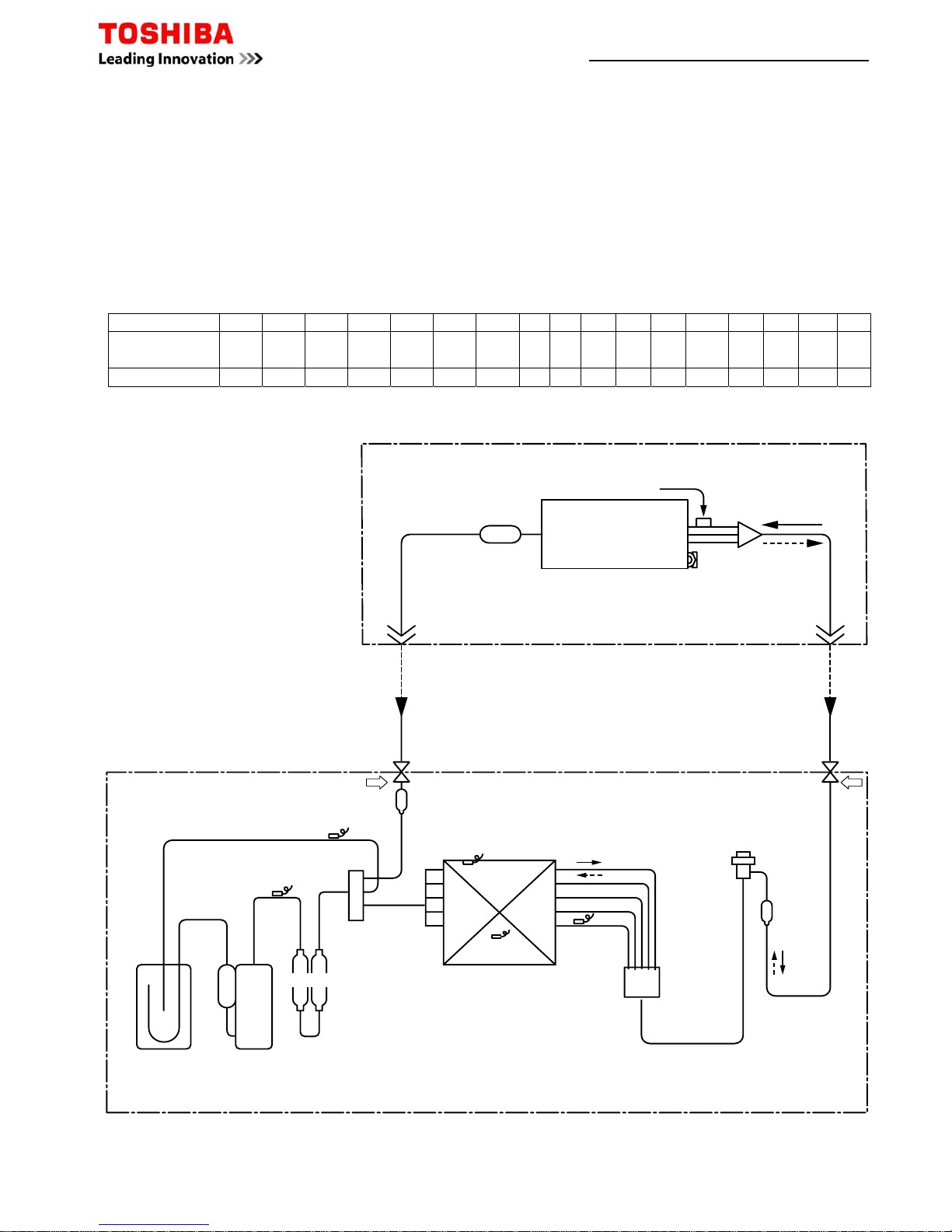
Indoor unit
Outdoor unit
Distributor
(Strainer incorporated)
TCJ sensor
Air heat exchanger
Strainer
Strainer
TC sensor
Strainer
Ball valve
Outer dia. ØA
Packed valve
Outer dia. ØB
Max.
50m
Min.
5m
TS sensor
TD sensor
TO sensor
TE
sensor
Distributor
4-way valve
(STF-0213Z
Ø25 × L210
Ø25 × L180
Twin Rotary
compressor
(DA220A2F – 20L)
Accumulator
(2500cc)
Heat exchanger
Outer side
Ø8, 2 rows, 20 steps
FP1.3 flat fin
Inner side
Ø9.52 row, 30 steps
FP1.5 flat fin
R410A 2.5kg
Muffler
Refrigerant pipe
at gas side
Ø15.9
Packet valve
Refrigerant pipe
at liquid side
Ø9.5
Packet valve
PMV
(Pulse Motor Valve)
(UKV-25D22)
Example for location of Sensors
TL sensor
Page 24 of 78

Stopped because of error of other indoor unit in a group
(Check codes of E03/L03/L07/L08)
Outdoor unit: Outdoor unit error
Protective device of
Outdoor unit: Inverter Idc operation ∗1
Outdoor unit: Position detection error
outdoor unit worked.
Outdoor unit high pressure protection
4-way valve system error (Indoor or outdoor unit judged.)
Negative phase detection error
Heat sink overheat error Outdoor unit error
Gas leak detection error
Outdoor unit discharge temp. error
Protective device of
∗1
Outdoor high pressure system error
outdoor unit worked.
Overflow was detected.
Protective device of indoor unit worked.
Indoor DC fan error
Miswiring between indoor unit and outdoor unit or connection erorr
(Communication stop between indoor and outdoor units)
Wire connection error between indoor units, Indoor power OFF
(Communication stop between indoor master and follower or between main
and sub indoor twin)
Communication error between CPUs on indoor unit P.C. board
Duplicated indoor unit No.
Setup error
Duplicated master units of remote controller
Receiving error
Receiving unit
Miswiring or wire connection error
Sending error
Communication stop
between receiving unit and indoor unit
Power supply OFF or miswiring between receiving unit and indoor unit
P31
Cause of trouble occurrence
P29
P26
P22
P20
P19
P15
P07
P05
P04
P03
P12
P10
E04
E18
E10
E09
E08
E03
E02
E01
—
Alternate flash
Check code
Operation
Timer Ready
Alternate flash
Operation
Timer Ready
Flash
Operation
Timer Ready
Flash
Operation
Timer Ready
No indication at all
Operation
Timer Ready
: Flash (0.5 sec.)
: Go on, : Go off,
Lamp indication
Lamp indication
Operation
Timer Ready
Alternate flash
Operation
Timer Ready
Alternate flash
Operation
Timer Ready
Simultaneous flash
Operation
Timer Ready
Simultaneous flash
Operation
Timer Ready
Flash
Operation
Timer Ready
Simultaneous flash
Operation
Timer Ready
Simultaneous flash
Check code
F01
F02
P10
F04
F06
F07
F08
F12
F13
F15
F29
F31
H01
H02
H03
H04
H06
L03
L07
L08
L09
L10
L20
L29
L30
L31
Cause of trouble occurrence
Heat exchanger sensor (TCJ) error
Heat exchanger sensor (TC) error Indoor unit sensor error
Heat exchanger sensor (TA) error
Discharge temp. sensor (TD) error
Temp. sensor (TE) error
Temp. sensor (TL) error
Temp. sensor (TO) error Sensor error of outdoor unit ∗1
Temp. sensor (TS) error
Temp. sensor (TH) error
Temp. Sensor miswiring (TE, TS)
Indoor EEPROM error
Outdoor EEPROM error
Compressor break down
Compressor lock
Current detection circuit error Outdoor compressor system error ∗1
Case thermostat worked.
Outdoor unit low pressure system error
Duplicated master indoor units
There is indoor unit of group connection → AUTO address
in individual indoor unit.
* If group construction and
Unsetting of group address
address are not normal
Missed setting when power supply turned on,
(Unset indoor capacity) automatically goes to address
setup mode.
Unset model type (Service board)
Duplicated indoor central addresses
Outdoor unit and other error Others
Outside interlock error
Negative phase error
Operation
Timer Ready
Simultaneous flash
Operation
Timer Ready
Alternate flash
—
—
During test run
Disagreement of cool/heat
(Automatic cool/heat setting to automatic cool/heat prohibited
model, or setting of heating to cooling-only model)
Page 25 of 78
Indoor Lamp Indication for Trouble Shooting - RAV Series

–
<I
Check Code List (Indoor)
¡
: Go on, ¥ : Flash, l : Go off ALT (Alternate): Alternate flashing when there are two flashing LED SIM (Simultaneous): Simultaneous flashing when there are two flashing LED
(Indoor unit detected)
²
When this warning was detected before group construction/address check finish at power supply was turned on, the mode shifts automatically to AUT O address setup mode .
(Remote controller detected)
(Central control devices detected)
Check code indication
TCC-LINK central &
Wired remote controller
E03
E04
E08
E10
E18
F01
F02
F10
F29
L03
L07
L08
L09
L20
L30
P01
P10
P12
P19
P31
Indoor Sensor lamp indication
Block indication
Operation
Timer Ready Flash
¥
ll
ll
¥
¥
ll
¥
ll
¥
ll
¥¥
l
ALT
¥¥
l
ALT
¥¥
l
ALT
¥¥
l
SIM
¥
l
¥
SIM
¥
l
¥
SIM
¥
l
¥
SIM
¥
l
¥
SIM
¥¡¥
SIM
¥¡¥
SIM
l
¥¥
ALT
l
¥¥
ALT
l
¥¥
ALT
¥
l
¥
ALT
¥
l
¥
ALT
Representative defective position
Regular communication error between indoor and
remote controller
Indoor/Outdoor serial error
Duplicated indoor addresses
²
Communication error between indoor MCU
Regular communication error between
indoor master and follower units
Indoor unit, Heat exchanger (TCJ) error
Indoor unit, Heat exchanger (TC) error
Indoor unit, Room temp. sensor (TA) error
Indoor unit, other indoor P.C. board error
Duplicated setting of indoor group master unit
²
There is group cable in individual indoor unit.
²
Unset indoor group address
²
Unset indoor capacity
Duplicated central control system address
Outside error input to indoor unit (Interlock)
Indoor unit, AC fan error
Indoor unit, overflow detection
Indoor unit, DC fan error
4-way valve system error
Other indoor unit error
Explanation of error contents
No communication from remote controller and network adapter
(Also no communication from central control system)
There is error on serial communication between indoor and outdoor units
Same address as yours was detected.
MCU communication error between main motor and micro computer
Regular communication between indoor master and follower units is impossible,
Communication between twin master (main) and follower (sub) units is impossible.
Open/short was detected on heat exchanger (TCJ).
Open/short was detected on heat exchanger (TC).
Open/short was detected on room temp. sensor (TA).
EEPROM error (Other error may be detected. If no error, automatic address is repeated.
There are multiple master units in a group.
When even one group connection indoor unit exists in individual indoor unit.
Indoor group address is unset.
Capacity of indoor unit is unset.
Duplicated setting of central control system address
Abnormal stop by outside error (CN80) input
An error of indoor AC fan was detected. (Fan motor thermal relay worked.)
Float switch worked.
Indoor DC fan error (Over-current/Lock, etc.) was detected.
In heating operation, an error was detected by temp. down of indoor heat exchanger sensor.
Follower unit in group cannot operate by warning from [E03/L03/L07/L08] of master unit.
Air conditioner operation
Automatic Operation
reset
continuation
¡
×
¡
×
¡
×
¡
×
¡
×
¡
×
¡
×
¡
×
××
××
××
××
××
¡
×
××
××
××
××
¡
×
¡
×
Check code indication
Wired remote controller
E01
E02
E09
Indoor Sensor lamp indication
Block indication
Operation
Timer Ready Flash
¥
ll
¥
ll
¥
ll
Representative defective position
No master remote controller, Remote controller
communication (Receive) error
Remote controller communication (Send) error
Duplicated master remote controller
Explanation of error contents
Signal cannot be received from indoor unit. Master remote controller was not set.
(including 2 remote controllers)
Signal cannot be sent to indoor unit.
In 2-remote controller control, both were set as master. (Indoor master unit stops warning
and follower unit continues operation.)
Air conditioner operation
Automatic Operation
reset
continuation
——
——
×
Check code indication
TCC-LINK central
C05
C06
C12
P30
Indoor Sensor lamp indication
Block indication
Operation
Timer Ready Flash
Is not displayed.
(Common use of
remote controller, etc.)
—
By warning unit
(Above-mentioned)
Representative defective position
Central control system communication (send) error
Central control system communication (receive) error
General-purpose device control interface batched warning
Group follower unit is defective.
Explanation of error contents
Signal sending operation of central control system is impossible.
There are multiple same central devices. (AI-NET)
Signal receiving operation of central control system is impossible.
An error on device connected to general-purpose device control interface of exclusiv e to
TCC-LINK/AI-NET
Group follower unit is defective .
(For remote controller, above-mentioned [∗∗∗] details are displayed with unit No.
Air conditioner operation
Automatic Operation
reset
continuation
——
——
——
——
NOTE: Even for the same contents of error such as communication error, the display of check code may differ according to detection device.When remote controller or central controller detects an error, it is not necessarily
related to operation of the air conditioner. In this list, the check codes that outdoor unit detects are not described.
Page 26 of 78
Indoor Lamp Indication for Trouble Shooting - RAV Series

–
<
Check Code List (Outdoor)
¡
: Go on, ¥ : Flash, l : Go off
ALT (Alternate): Alternate flashing when there are two flashing LED SIM (Simultaneous): Simultaneous flashing when there are two flashing LED
²
When this warning was detected before group construction/address check finish at power supply was turned on, the mode shifts automatically to AUTO address setup mode.
Remote
controller
indication
F04
F06
F08
F07
F12
F13
F15
F31
H01
H02
H03
H04
L10
L29
P03
P04
P05
P07
P15
P20
P22
P26
P29
E01
E02
E03
E04
E08
E09
E10
E18
L03
L07
L08
L09
L30
P19
Indoor Sensor lamp part
Block indication
Operation
Timer Ready Flash
¥¥¡
ALT
¥¥¡
ALT
¥¥¡
ALT
¥¥¡
ALT
¥¥¡
ALT
¥¥¡
ALT
¥¥¡
ALT
¥¥¡
SIM
l
¥
l
l
¥
l
l
¥
l
l
¥
l
¥¡¥
SIM
¥¡¥
SIM
¥
l
¥
ALT
¥
l
¥
ALT
¥
l
¥
ALT
¥
l
¥
ALT
¥
l
¥
ALT
¥
l
¥
ALT
¥
l
¥
ALT
¥
l
¥
ALT
¥
l
¥
ALT
¥
ll
¥
ll
¥
ll
ll
¥
¥
ll
¥
ll
¥
ll
¥
ll
¥
l
¥
SIM
¥
l
¥
SIM
¥
l
¥
SIM
¥
l
¥
SIM
¥¡¥
SIM
¥
l
¥
ALT
Representative defective position
Outdoor unit Discharge temp. sensor (TD) error
Outdoor unit Temp. sensor (TE, TS, TL) error
Outdoor unit Outside temp. sensor (TO) error
Outdoor unit Temp. sensor (TL) error
Outdoor unit Temp. sensor (TS) error
Outdoor unit Temp. sensor (TH) error
Outdoor unit Misconnection of temp. sensor (TE, TS)
Outdoor unit EEPROM error
Outdoor unit Compressor break down
Outdoor unit Compressor lock
Outdoor unit Current detection circuit error
Outdoor unit Case thermostat operation
Outdoor unit Setting error of service P.C. board type
Outdoor unit Other outdoor unit error
Outdoor unit Discharge temp. error
Outdoor unit
High pressure system error, Pow er supply voltage error
Power supply error
Outdoor unit Heat sink overheat
Gas leak detection
Outdoor unit High pressure system error
Outdoor unit Outdoor fan error
Outdoor unit Inverter Idc operation
Outdoor unit Position detection error
No remote controller master unit
Remote controller communication error
Remote controller send error
Regular communication error between indoor and
remote controller
Indoor/Outdoor serial error
Duplicated indoor addresses
²
Duplicated main remote controllers
Communication error between CPU
Regular communication error between master and
follower indoor units
Duplicated indoor master units
²
There is group cable in individual indoor unit.
²
Unset indoor group address
²
Unset indoor capacity
Outside error input to indoor unit (Interlock)
4-way valve inverse error
Detection
Outdoor
Outdoor
Outdoor
Outdoor
Outdoor
Outdoor
Outdoor
Outdoor
Outdoor
Outdoor
Outdoor
Outdoor
Outdoor
Outdoor
Outdoor
Outdoor
Outdoor
Outdoor
Outdoor
Outdoor
Outdoor
Outdoor
Outdoor
Remote
controller
Remote
controller
Indoor
Indoor
Indoor
Remote
controller
Indoor
Indoor
Indoor
Indoor
Indoor
Indoor
Indoor
Indoor
Outdoor
Explanation of error contents
Open/Short of discharge temp. sensor was detected.
Open/Short of heat exchanger temp. sensor was detected.
Miswiring between TE sensor and TS sensor
Open/Short of outside temp. sensor was detected.
Open/Short of heat exchanger temp. sensor was detected.
Open/Short of suction temp. sensor was detected.
Open/Short of heat sink temp. sensor (Board installed) was detected.
Misconnection of outdoor heat exchanger temp. sensor and suction temp. sensor was detected.
Outdoor P.C. board part (EEPROM) error was detected.
When reached min-Hz by current release control, short-circuited current (Idc) after
DC excitation was detected.
Compressor lock was detected.
Current detection circuit error
Case thermostat operation was detected.
When outdoor service P.C. board was used, model type select jumper setting was inappropriate.
1) Defective parts on outdoor P.C. board (MCU comm unication, EEPROM, TH sensor error)
2) When outdoor service P.C. board was used, model type selection was inappropriate.
3) Other error (Heat sink abnormal overheat, gas leak, 4-way valve inverse error) w as detected.
Error was detected by discharge temp. release control.
When case thermostat worked, error was detected by high release control from indoor/
outdoor heat exchanger temp. sensor. Power supply voltage error
Power supply voltage error
Abnormal overheat was detected by outdoor heat sink temp. sensor.
Abnormal overheat of discharge temp. or suction temp. was detected.
Error was detected by high release control from indoor/outdoor heat exchanger temp. sensor.
Error (Over-current, lock, etc.) was detected on outdoor fan drive circuit.
Short-circuited protective operation of compressor drive circuit element (G-Tr /IGBT) w ork ed .
Position detection error of compressor motor was detected.
Signal was not received from indoor unit.
Main remote controller was not set. (including 2 remote controllers)
Signal cannot be sent to indoor unit.
No communication from remote controller and network adapter
Serial communication error between indoor and outdoor
Same address as yours was detected.
In 2-remote controller control, both were set as master.
(Indoor master unit stops warning and follower unit continues operation.)
MCU communication error between main motor and micro computer
Regular communication was impossible between master and follower indoor units.
Communication between twin master (Main unit) and follower (sub unit) was impossible.
There are multiple master units in a group.
When even one group connection indoor unit exists in individual indoor unit
Indoor address group was unset.
Capacity of indoor unit was unset.
Abnormal stop by CN80 outside error input
In heating operation, error was detected by temp. down of indoor heat exchanger or temp. up ofTE, TS.
Automatic Operation
reset
continuation
××
××
¡¡
××
××
××
××
××
××
××
××
××
××
××
××
××
××
××
××
××
××
××
××
——
——
¡
×
¡
×
¡
××
¡
¡
×
××
××
××
××
××
¡
×
Page 27 of 78
Indoor Lamp Indication for Trouble Shooting - RAV Series

Apps Store Fault Codes – All Commercial & VRF Systems
Download
Toshiba Fault
Codes
from your Apps Store
or go to web page Toshiba-calc.co.uk/fault-codes/
Example: 1
Local controller displaying fault code E04
Enter E04 and select Find Fault
VRF fault codes can be model specific and may require
condenser model reference in Fault Code
Example: 2
Local controller displaying fault code L29
Condenser displaying sub-code 07
Model of condenser MMY-MAP1604HT8-E
Enter L29071604 and select Find Fault
Please note; codes can be entered with or without character spaces, spaces ignored
in text strings.
–
<
¡
: Go on, ¥ : Flash, l : Go off
ALT (Alternate): Alternate flashing when there are two flashing LED SIM (Simultaneous): Simultaneous flashing when there are two flashing LED
Remote
controller
indication
F01
F02
F10
F29
P01
P10
P12
P31
—
—
L20
—
Indoor Sensor lamp part
Block indication
Operation
Timer Ready Flash
¥¥
l
ALT
¥¥
l
ALT
¥¥
l
ALT
¥¥
l
SIM
l
¥¥
ALT
l
¥¥
ALT
l
¥¥
ALT
¥
l
¥
ALT
By unit with warning No.
ALT
—
¥¡¥
SIM
—
Representative defective position
Indoor unit Heat exchanger sensor (TCJ) error
Indoor unit Heat exchanger sensor (TC) error
Indoor unit Room temp. sensor (TA) error
Indoor unit Other indoor P.C. board error
Indoor unit Indoor fan error
Indoor unit Overflow detection
Indoor unit Indoor fan error
Other indoor unit error
Error in indoor group
LAN system communication error
LAN system communication error
There are multiple communication adapters.
Detection
Indoor
Indoor
Indoor
Indoor
Indoor
Indoor
Indoor
Indoor
Network adapter
Network adapter/
Center
Network adapter/
Center
Network adapter
Explanation of error contents
Open/Short of heat exchanger (TCJ) was detected.
Open/Short of heat exchanger (TC) was detected.
Open/Short of room temp. (TA) was detected.
EEPROM error (Other error may be detected. If no error, automatic address is repeated.
Indoor AC fan error was detected. (Fan thermal relay worked.)
Float switch worked.
Indoor fan error (Over-current / Lock, etc.) was detected.
Other indoor under condition of warning in group. E03/L07/L03/L08 warning
Sub remote controller error in a group
(Details of remote controller are displayed with unit No. Only central control side is displayed.)
Communication error of central control system signal
∗ Is not displayed on the remote controller
Duplicated indoor address of central control system communication
There are multiple communication adapters on remote controller communication line.
Automatic Operation
reset
continuation
¡
×
¡
×
¡
×
××
××
××
××
¡
×
——
¡¡
¡
×
¡¡
Page 28 of 78
Indoor Lamp Indication for Trouble Shooting - RAV Series

Fault Codes – All Commercial & VRF Systems
Do Not turn off the power supply before reading the fault codes, doing so will clear the diagnostic memory.
Caution must be taken when removing the access covers, as high voltages are present.
Fault diagnosis is available at three locations within the Air Conditioning system. :1 Remote Controller - press the check button 2 Multi Controller - rotate the display switch to position 1
3 Central Controller - press the check button (if installed) 4 Outdoor Unit Switch position (variable dependent upon model): –
2 Pipe Super Multi 2, 3 & 8; 3 Pipe Super Multi 2 & 0;
3 Pipe SMI 2 & 0 2 Pipe Modular Multi MMY 1, 1, 1
3 Pipe Modular Multi MMY 1, 1, 1
Page 29 of 78
Code Fault Description
04
Split A/C equipment indoor to outdoor communication failure / VRF equipment could also be attributed to communication breakdown between
condenser PCB's. Likely cause Indoor PCB / condenser PCB / Interconnecting cable damage / transformer used to power condenser PCB
08
Reverse change in temperature. Detected by indoor evaporator sensor (TC). Likely cause 4 way valve. 4 way reversing valve energised for heating
operation only
09
Frost conditions detected / No temperature change. Detected indoors by evaporator sensor (TC). Likely cause poor airflow, lack of refrigerant,
overheating compressor
11 Indoor fan trouble. Detected indoors. Likely cause fan motor, PCB
12 EEPROM Failure on PCB. Detected indoors (replace indoor PCB)
14
Inverter compressor PCB short circuit. Detected at outdoor. Likely cause blown fuses supplying inverter pack, faulty IPDU(inverter board) or
component within inverter pack, electrical fault on inverter compressor
15 Multi-Control box error. Detected indoors (interrogate Multi-Control box for additional faults by setting display switch @ position 1)
17 Abnormal current detection on inverter compressor. Detected at outdoor. (replace IPDU PCB (inverter board))
18 Condenser coil sensor fault. Detected indoors. Likely cause TE/TE1 sensor condition or outdoor PCB fault sensor value 20°c=12.5k ohms
19
Liquid or compressor discharge sensor fault. Likely cause TL,TD sensor condition or PCB fault TL sensor value 20°c=12.5k ohms TD sensor value
20°c=63k ohms
20 Condenser PCB faulty (replace main PCB)
21
2 pipe VRF & Split A/C equipment High Pressure switch activation 425psi-29bar _ 3 pipe VRF equipment, interrogate condenser PCB for additional fault
code. Detected at outdoor. Likely cause split A/C equipment faulty H.P. switch, restriction in refrigerant flow, fan motor failure, poor airflows / VRF
equipment set condenser interface PCB switches as follows SW1 @ position 2 & SW2 @ position 0 (see sub codes Er21 or ErAd)
22 Excessive high pressure. Detected at outdoor. Likely cause abnormal characteristics of Pd transducer, refrigerant restriction/blockage
80 Multi-Control box Th(A) sensor fault. Likely cause TH(A) sensor or M/C box PCB sensor value 20°c=12.5k ohms
81 Multi-Control box Th(B) sensor fault. Likely cause TH(B) sensor or M/C box PCB sensor value 20°c=12.5k ohms
82 Multi-Control box Th(C) sensor fault. Likely cause TH(C) sensor or M/C box PCB sensor value 20°c=12.5k ohms
83 Multi-Control box Th(D) sensor fault. Likely cause TH(D) sensor or M/C box PCB sensor value 20°c=12.5k ohms
84 Multi-Control box Th(X) sensor fault. Likely cause TH(X) sensor or M/C box PCB sensor value 20°c=12.5k ohms

Page 30 of 78
Code Fault Description
87 Phase missing phase. Detected at outdoor. Likely cause abnormal power supply
88 Multi-Control box does not recognise condenser capacity. Likely cause interconnecting cable damage, outdoor PCB fault
89 Indoor capacity to high. Likely cause loss of combination within group of modularised condensers
93 Indoor coil sensor fault. Detected indoors. Likely cause TC1 sensor condition or indoor PCB fault sensor value 20°c=12.5k ohms
94 Indoor coil sensor fault. Detected indoors. Likely cause TC2 sensor condition or indoor PCB fault sensor value 20°c=12.5k ohms
95
Communication failure on P&Q network (indoor/outdoor communication). Detected indoors & outdoors. Likely cause network cable condition, PCB
failure indoor or outdoor
96 Indoor unit count too high. Detected at outdoor. Likely cause indoor capacity vs. outdoor capacity Incorrect, too many indoor units connected
97 Central control communication error. Detected at central controller & indoors. Likely cause indoor power failure, central address error, cable damage
98 Duplicated zone address. Likely cause incorrectly assigned central control addresses
99
No communication from indoor to remote controller. Detected by hard-wired remote controller. Likely cause faulty indoor PCB, remote controller or
cable damage
0b
Indoor float switch open circuit as result of high condensation levels within drip tray. Detected indoors. Likely cause faulty float switch, faulty lift pump,
debris blocking drain
0c Return air sensor fault. Detected indoors. Likely cause TA sensor condition or indoor PCB fault sensor value 20°c=12.5k ohms
0d Coil sensor fault. Detected indoors. Likely cause TC sensor condition or indoor PCB fault sensor value 20°c=12.5k ohms
1C Outdoor error. Detected indoors (interrogate condenser for additional faults)
1d High Inverter dc current. Detected at outdoor. Likely cause imbalance in compressor voltage, excessive amps by inverter compressor
1E
High compressor discharge temperature. Detected at outdoor. Likely cause low refrigerant, poor refrigerant flow, poor airflows, TD sensor condition
sensor value 20°c=63k ohms
1F High Inverter ac current. Detected at outdoor. Likely cause imbalance in compressor voltage, excessive amps by inverter compressor
8d
Outdoor unit quantity fallen (loss of communication between condensers). Detected at outdoor. Likely cause power interruption, BUS communication
cable condition
8E Outdoor units quantity too high. Detected at outdoor. Likely cause too many condensers connected
8F Outdoor unit address incorrect. Detected at outdoor. Likely cause multiple modularised condenser having SW 9 ON, Interface PCB failure
9A
No temperature change on evaporator. Detected by indoor evaporator sensor TC1. Likely cause miss-wiring, restriction in refrigerant flow, lack of
refrigerant
9F
Insufficient temperature change on evaporator. Detected indoors. Likely cause miss-wiring, restriction in refrigerant flow, lack of refrigerant, TC1,TC2
& TA sensor condition sensor value 20°c=12.5k ohms
A0 Compressor discharge sensor fault. Detected at outdoor. Likely cause TD1/ThD1 sensor condition or Interface PCB sensor value 20°c=63k ohms
A1 Compressor discharge sensor fault. Detected at outdoor. Likely cause TD2/ThD2 sensor condition or Interface PCB sensor value 20°c=63k ohms
A2 Compressor suction sensor fault. Detected at outdoor. Likely cause TS1/ThS sensor condition or interface PCB sensor value 20°c=12.5k ohms
A6
High compressor discharge temperature. Detected at outdoor. by TD1. Likely cause low refrigerant, poor refrigerant flow and airflows & TD2 sensor
condition sensor value 20°c=63k ohms
A7
High compressor suction temperature > 40°C. Detected at outdoor. Likely cause severe gas shortage, TS sensor condition, interface PCB sensor value
20°c=12.5k ohms

Page 31 of 78
Code Fault Description
AA High side pressure sensor fault. Detected at outdoor. (Replace Pd pressure transducer)
Ab Pressure transducer error. Detected at outdoor. Likely cause abnormal running pressures, abnormal PS / Pd characteristics, interface PCB
AE
High compressor discharge temperature @ low inverter speed. Detected at outdoor. Likely cause TD1 sensor condition, insufficient refrigerant sensor
value 20°c=63k ohms
AF Phase rotation incorrect. Detected at outdoor. Likely cause abnormal phase order, missing phase to outdoor unit
b4
Low pressure transducer error or misreading fault. Detected at outdoor. Likely cause incorrect characteristics of suction pressure transducer (PS,
interface PCB faulty
b5 External input activation, refrigerant leak detection system (Call Toshiba's technical helpline for further details 0870 843 0333)
b6 External input activation, refrigerant leak detection system (Call Toshiba's technical helpline for further details 0870 843 0333)
b7 Indoor group follower error. Detected at central controller (interrogate local controller by pressing check for additional fault codes)
b9 Pressure sensor fault. Detected indoors. Likely cause evaporator pressure sensor unplugged, pressure sensor open circuit replace sensor
bb
High compressor discharge temperature. Detected at outdoor. by TD2. Likely cause low refrigerant, poor refrigerant flow and airflows & TD2 sensor
condition sensor value 20°c=63k ohms
bE
Low pressure trip. Detected outdoor by PS transducer. Likely cause suction pressure transducer condition (PS), interface PCB fault restriction in
refrigerant flow, lack of refrigerant
C05 Command sending error. Detected on Central Controller. Likely cause power loss at indoor unit group, network cable condition)
C06 Command receiving error. Detected on Central Controller. Likely cause power loss at indoor unit group, network cable condition)
d1 Master condenser setup alarm. Detected at outdoor. Likely cause multiple inverter outdoor units connected, faulty interface PCB)
d2 Fault within follower condenser. Detected at outdoor. (retrieve additional fault code from follower condensers)
d3 IPDU PCB overheat (inverter board). Detected at outdoor. Likely cause clogged heat-sink fins, poorly secured or faulty IPDU PCB)
d4 Oil sensor fault. Detected at outdoor. Likely cause TK1 sensor condition or outdoor PCB fault sensor value 20°c=63k ohms)
d5 Oil sensor fault. Detected at outdoor. Likely cause TK2 sensor condition or outdoor PCB fault sensor value 20°c=63k ohms)
d6 Oil sensor fault. Detected at outdoor. Likely cause TK3 sensor condition or outdoor PCB fault sensor value 20°c=63k ohms)
d7 Low oil detection. Detected at outdoor. Likely cause TK1, TK2 & TK3 sensor condition, interface PCB, lack of refrigerant sensor value 20°c=63k ohms)
d8 Oil temperature alarm. Detected at outdoor. Likely cause TK1 sensor location or condition, outdoor PCB fault sensor value 20°c=63k ohms
d9 Oil temperature alarm. Detected at outdoor. Likely cause TK2 sensor location or condition, outdoor PCB fault sensor value 20°c=63k ohms
dA Abnormal overheat of heat-sink. Detected at outdoor. Likely cause clogged heat-sink fins, poorly secured or faulty IPDU board
db
No oil flow detected. Detected at outdoor. Likely cause TK1, TK2 & TK3 sensor location or condition, interface PCB, blockage within SV3C sensor value
20°c=63k ohms
dC
High temperature oil alarm. Detected at outdoor. Likely cause TK1 sensor condition, interface PCB fault, high ambient running conditions >43°c sensor
value 20°c=63k ohms
dd
Temperature change when condensers in off cycle. Detected at outdoor. Likely cause PMV passing within condenser, discharge & suction pressure
transducer error (PS & Pd characteristics), interface PCB fault
dE Indoor unit automatic addressing failure. Detected at outdoor. Likely cause indoor PCB configuration error, indoor PCB faulty
dF Outdoor unit automatic address failure. Detected at outdoor. Likely cause interface PCB fault

Page 32 of 78
Code Fault Description
E01
Communication error between indoor unit and remote controller. Detected by remote controller. Likely cause indoor PCB, remote controller, incorrect
switch position on rear of remote controller, all switches normally down
E02 Sending error of local remote controller. Detected by remote controller. Likely cause replace remote controller
E03
Communication error between indoor unit and central remote controller. Detected indoors. Likely cause indoor network adapter, central remote
controller
E04
Communication failure between indoor and outdoor units. Detected indoors. Likely cause split A/C=indoor PCB, outdoor PCB, interconnecting cable
condition, compressor klixon open circuit. VRF system=power loss at condenser, U1/U2 network cable condition
E06 Decrease in quantity of indoor units. Detected indoors. Likely cause power loss at indoor unit, indoor PCB fault, A&B controller cable condition
E07
Communication failure between indoor and outdoor units. Detected at outdoor. Likely cause interconnecting cable condition, outdoor PCB switch
position SW30 bit 1 & 2 must be placed in ON position for test
E08 Duplicated indoor address. Detected indoors. Likely cause incorrect setting of BUS addresses when under central control
E09 Duplicated master remote controllers. Detected indoors. Likely cause two local remote controller connected on A&B network
E1
Activation of high pressure switch on D.O.L (Fixed speed) compressor 1. Detected at outdoor. Likely cause fan motor trouble, poor airflows, restricted
refrigerant flow
e1 80 Multi-Control box 1 Th(A) sensor fault. Likely cause TH(A) sensor or M/C box PCB sensor value 20°c=12.5k ohms
e1 81 Multi-Control box 1 Th(B) sensor fault. Likely cause TH(B) sensor or M/C box PCB sensor value 20°c=12.5k ohms
e1 82 Multi-Control box 1 Th(C) sensor fault. Likely cause TH(C) sensor or M/C box PCB sensor value 20°c=12.5k ohms
e1 83 Multi-Control box 1 Th(D) sensor fault. Likely cause TH(D) sensor or M/C box PCB sensor value 20°c=12.5k ohms
e1 84 Multi-Control box 1 Th(X) sensor fault. Likely cause TH(X) sensor or M/C box PCB sensor value 20°c=12.5k ohms
E10 Communication Error at indoor PCB. Detected indoors. Likely cause replace indoor PCB
E12
Automatic addressing error. Detected at outdoor. Likely cause incorrect self-addressing sequence, repeat self-addressing procedure. Retrieve fault sub-
code from condenser interface PCB by placing rotary dials to position 1 / 1 / 1 for diagnosis.
E12 01 Automatic addressing error. Detected at outdoor. Indoor / Outdoor communication
E12 02 Automatic addressing error. Detected at outdoor. Outdoor / Outdoor communication
E15
Automatic self-addressing failure. Detected at outdoor. Likely cause SW30 bit 1 & 2 in OFF position, switch both ON before self-addressing
commenced, interface pcb failure
E16
Indoor unit count or capacity to high. Detected at outdoor. Likely cause if condenser PCB displays sub code 00=indoor capacity vs. condenser to high.
If sub code at condenser reads 01=indoor unit count/quantity to high. Retrieve fault sub-code from condenser interface PCB by placing rotary dials to
position 1 / 1 / 1 for diagnosis.
E16 00 Indoor unit capacity to high. Detected at outdoor. Likely cause indoor unit capacity to high vs. condenser capacity
E16 01 Indoor unit count to high. Detected at outdoor. Likely cause indoor unit count to high vs. outdoor upper limit
E18
Communication failure between indoor units. Detected indoors. Likely cause indoor power loss, A&B controller cable condition. Twin, triple & Quad
applications E18 can result from E04 fault code
E19
Outdoor header error. Detected at outdoor. Likely cause if condenser PCB displays sub code 00=power loss to indoor units or U1/U2 network cable
condition. If sub code reads 01=incorrect wiring between modularised condensers. Retrieve fault sub-code from condenser interface PCB by placing
rotary dials to position 1 / 1 / 1 for diagnosis.

Page 33 of 78
Code Fault Description
E19 00 Outdoor header error. Detected at outdoor. Likely cause power loss to indoor units, U1/U2 network cable condition, SW30 bit 1 & 2 must be ON to test
E19 01 Outdoor header error. Detected at outdoor. Likely cause incorrect wiring between modularised condensers
e2 80 Multi-Control box 2 Th(A) sensor fault. Likely cause TH(A) sensor or M/C box PCB sensor value 20°c=12.5k ohms
e2 81 Multi-Control box 2 Th(B) sensor fault. Likely cause TH(B) sensor or M/C box PCB sensor value 20°c=12.5k ohms
e2 82 Multi-Control box 2 Th(C) sensor fault. Likely cause TH(C) sensor or M/C box PCB sensor value 20°c=12.5k ohms
e2 83 Multi-Control box 2 Th(D) sensor fault. Likely cause TH(D) sensor or M/C box PCB sensor value 20°c=12.5k ohms
e2 84 Multi-Control box 2 Th(X) sensor fault. Likely cause TH(X) sensor or M/C box PCB sensor value 20°c=12.5k ohms
E20
One or more systems connected on network during self-addressing procedure. Detected at outdoor. Likely cause if condenser PCB displays sub code
01=multiple outdoor systems connected on U3/U4 network, miss-wiring or central control relay connecter in-place. If sub code reads 02=indoor units
from other line connected, miss-wiring or central control relay connecter in-place. Retrieve fault sub-code from condenser interface PCB by placing
rotary dials to position 1 / 1 / 1 for diagnosis.
E20 01
Multiple indoor system line numbers connected on network during self-addressing procedure. Detected at outdoor. Likely cause miss-wiring of indoor
network cable, central control relay connecter together during self-address
E20 02
Multiple outdoor system numbers connected on network during self-address procedure. Detected at outdoor. Likely cause miss-wiring of outdoor units,
central control relay/plug connected during self-address
E23 Communication error between outdoor units. Detect outdoors. Likely cause U5/U6 cable condition, interface PCB fault
E25 Duplicated follower outdoor unit address. Detected at outdoor. Likely cause error in manually assigning addresses, allow system to self-address
E26 Decrease in quantity of outdoor units connected. Detected at outdoor. Likely cause power loss at condensers, U5/U6 cable condition
E28
Outdoor follower fault. Detected at outdoor. Likely cause lead condenser OK, follower condenser has suffered fault, retrieve second fault code from
follower condenser
E31
IPDU/PCB board communication error. Detected at outdoor. Likely cause loss in communication between condenser PCB's. Retrieve fault sub-code
from condenser interface PCB by placing rotary dials to position 1 / 1 / 1 for diagnosis.
E31 01
Compressor 1 IPDU board communication error. Detected at outdoor. Likely cause check communication cable linking all PCB's, replace Compressor 1
IPDU board
E31 02
Compressor 2 IPDU board communication error. Detected at outdoor. Likely cause check communication cable linking all PCB's, replace Compressor 2
IPDU board
E31 03
Compressor 1 & 2 IPDU board communication error. Detected at outdoor. Likely cause check communication cable linking all PCB's, replace
Compressor 1 & 2 IPDU board
E31 04
Communication failure between PCB's within condenser. Detected at outdoor. Fault Code is outdoor model series specific e.g. MMY-MAP###1HT8-E,
MMY-AP###2HT8-E or MMY-MAP###4HT8-E therefore example fault code for E3104 will be (MMY-MAP0801HT8-E (series 1), MMY-MAP0802HT8-E
(series 2), MMY-MAP0804HT8-E (series 4) search E31041, E31042 or E31044
E31 04 1 Fan IPDU board communication error. Detected at outdoor. Likely cause check communication cable linking all PCB's, replace fan IPDU board
E31 04 2 Fan IPDU board communication error. Detected at outdoor. Likely cause check communication cable linking all PCB's, replace fan IPDU board
E31 04 4
Compressor 3 IPDU board communication error. Detected at outdoor. Likely cause check communication cable linking all PCB's, replace Compressor 3
IPDU board

Page 34 of 78
Code Fault Description
E31 05
Communication failure between PCB within condenser. Fault Code is outdoor model series specific e.g. MMY-MAP###1HT8-E, MMY-AP###2HT8-E or
MMY-MAP###4HT8-E therefore example fault code for E3105 will be (MMY-MAP0801HT8-E (series 1), MMY-MAP0802HT8-E (series 2), MMY-
MAP0804HT8-E (series 4) search E31051, E31052 or E31054
E31 05 1
Compressor 1 IPDU & fan IPDU board communication error. Detected at outdoor. Likely cause check communication cable linking all PCB's, replace
Compressor 1 IPDU & fan IPDU board
E31 05 2
Compressor 1 IPDU & fan IPDU board communication error. Detected at outdoor. Likely cause check communication cable linking all PCB's, replace
Compressor 1 IPDU & fan IPDU board
E31 05 4
Compressor 1 & 3 IPDU board communication error. Detected at outdoor. Likely cause check communication cable linking all PCB's, replace
Compressor 1 & 3 IPDU board
E31 06
Communication failure between PCB within condenser. Detected at outdoor. Fault Code is outdoor model series specific e.g. MMY-MAP###1HT8-E,
MMY-AP###2HT8-E or MMY-MAP###4HT8-E therefore example fault code for E3106 will be (MMY-MAP0801HT8-E (series 1), MMY-MAP0802HT8-E
(series 2), MMY-MAP0804HT8-E (series 4) search E3101, E31062 or E31064
E31 06 1
Compressor 2 IPDU & fan IPDU board communication error. Detected at outdoor. Likely cause check communication cable linking all PCB's, replace
Compressor 2 IPDU & fan IPDU board
E31 06 2
Compressor 2 IPDU & fan IPDU board communication error. Detected at outdoor. Likely cause check communication cable linking all PCB's, replace
Compressor 2 IPDU & fan IPDU board
E31 06 4
Compressor 2 & 3 IPDU board communication error. Detected at outdoor. Likely cause check communication cable linking all PCB's, replace
Compressor 2 & 3 IPDU board
E31 07
Communication failure between PCB within condenser. Detected at outdoor. (4 Series Condenser Compressor 1, 2 & 3 IPDU board communication
error). (1&2 Series condenser communication error between PCB within condenser) likely cause phase missing on power supply, replace interface PCB
E31 07 1
Communication error between PCB within condenser. Detected at outdoor. Likely cause check communication cable linking all PCB's, phase missing on
power supply, replace interface PCB
E31 07 2
Communication error between PCB within condenser. Detected at outdoor. Likely cause check communication cable linking all PCB's, phase missing on
power supply, replace interface PCB
E31 07 4
Compressor 1, 2 & 3 IPDU board communication error. Detected at outdoor. Likely cause check communication cable linking all PCB's, replace
Compressor 1, 2 & 3 IPDU board
E31 08 Fan IPDU board communication error. Detected at outdoor. Likely cause check communication cable linking all PCB's, replace fan IPDU board
E31 09
Compressor 1 IPDU & fan IPDU board communication error. Detected at outdoor. Likely cause check communication cable linking all PCB's, replace
Compressor 1 IPDU & fan IPDU board
E31 0A
Compressor 2 IPDU & fan IPDU board communication error. Detected at outdoor. Likely cause check communication cable linking all PCB's, replace
Compressor 2 IPDU & fan IPDU board
E31 0B
Compressor 1 & 2 IPDU board & fan IPDU board communication error. Detected at outdoor. Likely cause check communication cable linking all PCB's,
replace Compressor 1 & 2 IPDU PCB & fan IPDU board
E31 0C
Compressor 3 IPDU board & fan IPDU board communication error. Detected at outdoor. Likely cause check communication cable linking all PCB's,
replace Compressor 3 IPDU board & fan IPDU board
E31 0d
Compressor 1 & 3 IPDU board & fan IPDU board communication error. Detected at outdoor. Likely cause check communication cable linking all PCB's,
replace Compressor 1 & 3 IPDU board & fan IPDU board

Page 35 of 78
Code Fault Description
E31 0E
Compressor 2 & 3 IPDU board & fan IPDU board communication error. Detected at outdoor. Likely cause check communication cable linking all PCB's,
replace Compressor 2 & 3 IPDU PCB & fan IPDU board
E31 0F
Communication error between PCB within condenser. Detected at outdoor. Likely cause check communication cable linking all PCB's, phase missing on
power supply, replace interface PCB
E5
Activation of high pressure switch or internal overheat (klixon on INVERTER compressor only. Detected at outdoor. Likely cause fan motor trouble,
poor airflows, poor refrigerant flow, insufficient refrigerant
E6
Activation of compressor klixon or contactor overload on D.O.L (Fixed speed compressor 1. Detected at outdoor. Likely cause poor refrigerant flow,
insufficient refrigerant, excessive amps by compressor
Eb
Resulting from b6 fault code generated at indoor unit. Detected at outdoor. (b6=External input activation, refrigerant leak detection system (Call
Toshiba's technical helpline for further details 0870 843 0333)
Er 14
Inverter compressor low voltage. Detected at outdoor. Likely cause AC fuse disconnection, faulty component within compressor inverter circuit,
electrical failure of compressor
Er 1d High Inverter dc current. Detected at outdoor. Likely cause imbalance in compressor voltage, excessive amps by inverter compressor
Er 1F High Inverter ac current. Detected at outdoor. Likely cause imbalance in compressor voltage, excessive amps by inverter compressor
Er 21
Inverter compressor trip. Detected at outdoor. Likely cause activation of high pressure switch 425psi-29bar / internal overheat (klixon) on inverter
compressor only
Er A0 Compressor discharge sensor fault. Detected at outdoor. Likely cause TD1/ThD1 sensor condition or Interface PCB sensor value 20°c=63k ohms
Er A1 Compressor discharge sensor fault. Detected at outdoor. Likely cause TD2/ThD2 sensor condition or Interface PCB sensor value 20°c=63k ohms
Er A2 Compressor suction sensor fault. Detected at outdoor. Likely cause TS1/ThS sensor condition or interface PCB sensor value 20°c=12.5k ohms
Er A4 Ambient air sensor fault. Detected at outdoor. Likely cause Th0 sensor condition or interface PCB sensor value 20°c=12.5k ohms
Er A5 Condenser coil sensor fault. Detected at outdoor. Likely cause ThE sensor condition or interface PCB fault sensor value 20°c=12.5k ohms
Er A6
High compressor discharge temperature. Detected at outdoor. by TD1,TD2,ThD1 & ThD2. Likely cause low refrigerant, poor refrigerant flow and
airflows & TD sensor condition sensor value 20°c=63k ohms
Er A7
High compressor suction temperature > 40°C. Detected at outdoor. Likely cause severe gas shortage, TS sensor condition, interface PCB sensor value
20°c=12.5k ohms
Er AA High side pressure sensor fault. Detected at outdoor. (Replace Pd pressure sensor)
Er Ad
Fixed speed compressor trip (D.O.L). Detected at outdoor. Likely cause activation of high pressure switch 425psi-29bar / internal overheat (klixon) /
phase rotation PCB / D.O.L contactor overload trip
Er AE Low Pressure trip < 3 psig. Detected at outdoor. by L.P. switch. Likely cause refrigerant loss, restriction in refrigerant flow
Er AF Phase rotation incorrect. Detected at outdoor. Likely cause abnormal phase order, missing phase to outdoor unit
F0
Activation of high pressure switch on D.O.L (Fixed speed) compressor 2. Detected at outdoor. Likely cause fan motor trouble, poor airflows, restricted
refrigerant flow
F01 TCj Coil sensor fault. Detected indoors. Likely cause TCj sensor condition or indoor PCB fault sensor value 20°c=12.5k ohms
F02 TC2 or TC Coil sensor fault. Detected indoors. Likely cause TC2 / TC sensor condition or indoor PCB fault sensor value 20°c=12.5k ohms
F03 TC1 Coil sensor fault. Detected indoors. Likely cause TC1 sensor condition or indoor PCB fault sensor value 20°c=12.5k ohms

Page 36 of 78
Code Fault Description
F04 Td1 sensor fault. Detected at outdoor. Likely cause compressor discharge sensor condition (Td1) or outdoor PCB fault sensor value 20°c=63k ohms
F05 Td2 sensor fault. Detected at outdoor. Likely cause compressor discharge sensor condition (Td2) or outdoor PCB fault sensor value 20°c=63k ohms
F06
TE or TS Sensor fault. Detected at outdoor. Likely cause Heat exchange sensor condition (TE / TE1 / TE2). Suction line sensor condition (TS) or
outdoor PCB fault sensor value 20°c=12.5k ohms. Retrieve fault sub-code from condenser interface PCB by placing rotary dials to position 1 / 1 / 1 for
diagnosis.
F06 01 TE1 Sensor fault. Detected at outdoor. Likely cause Heat exchange sensor condition (TE1) or outdoor PCB fault sensor value 20°c=12.5k ohms
F06 02 TE2 Sensor fault. Detected at outdoor. Likely cause Heat exchange sensor condition (TE2) or outdoor PCB fault sensor value 20°c=12.5k ohms
F07 TL Sensor fault. Detected at outdoor. Likely cause Liquid line sensor condition (TL) or outdoor PCB fault sensor value 20°c=12.5k ohms
F08 TO Sensor fault. Detected at outdoor. Likely cause Ambient air sensor condition (TO) or outdoor PCB fault sensor value 20°c=12.5k ohms
F1
Activation of compressor klixon or contactor overload on D.O.L (Fixed speed compressor 2). Detected at outdoor. Likely cause poor refrigerant flow,
insufficient refrigerant, excessive amps by compressor
F10 TA Sensor fault. Detected indoors. Likely cause Return air sensor condition (TA) or indoor PCB fault sensor value 20°c=12.5k ohms
F12 TS Sensor fault. Detected at outdoor. Likely cause Suction line sensor condition (TS / TS1 / TS2) or outdoor PCB fault sensor value 20°c=12.5k ohms
F13
Compressor IPDU board overheat. Detected at outdoor. Likely cause poor contact to heat-sink, IPDU board fault. Fault sub-code required to determine
which board has suffered overheat 01=IPDU1 overheated 02=IPDU2 overheated 03=IPDU3 overheated. Retrieve fault sub-code from condenser
interface PCB by placing rotary dials to position 1 / 1 / 1 for diagnosis.
F13 01 Compressor 1 IPDU board overheat. Detected at outdoor. Likely cause poor contact to heat-sink, replace compressor IPDU board 1
F13 02 Compressor 2 IPDU board overheat. Detected at outdoor. Likely cause poor contact to heat-sink, replace compressor IPDU board 2
F13 03 Compressor 3 IPDU board overheat. Detected at outdoor. Likely cause poor contact to heat-sink, replace compressor IPDU board 3
F15
Outdoor temperature sensor error. Detected at outdoor. Likely cause VRF equipment=Heat exchange (TE) sensor condition/location or Liquid line (TL)
sensor condition/location, outdoor PCB fault Split equipment=Suction sensor (TS) condition/location Heat exchange sensor (TE) condition/location,
outdoor PCB fault sensor value 20°c=12.5k ohms
F16
Pressure sensors miss-reading. Detected at outdoor. Likely cause incorrect characteristics of compressor discharge (Pd) & compressor suction (PS)
pressure sensor or total loss of refrigerant
F22 Td3 sensor fault. Detected at outdoor. Likely cause compressor discharge sensor condition (Td3) or outdoor PCB fault sensor value 20°c=63k ohms
F23 Compressor suction pressure sensor fault. Detected at outdoor. Likely cause Suction transducer (PS) fault, outdoor PCB fault
F24 Compressor discharge pressure sensor fault. Detected at outdoor. Likely cause Suction transducer (Pd) fault, outdoor PCB fault
F29 Indoor PCB fault. Detected indoors. Likely cause replace indoor PCB
F31
Outdoor EEPROM Error. Detected at outdoor. Likely cause VRF equipment=power interruption, replace interface PCB Split equipment=replace
condenser CDB board
H01
Excessive amps drawn by compressor. Detected at outdoor. Likely cause imbalance in voltage supplied from IPDU board to compressor, compressor
lock / seizure. Retrieve sub-code for VRF from condenser to determine which compressor suffered failure 01=compressor1, 02=compressor2 &
03=compressor3. Retrieve fault sub-code from condenser interface PCB by placing rotary dials to position 1 / 1 / 1 for diagnosis.
H01 01
Excessive amps drawn by compressor 1. Detected at outdoor. Likely cause imbalance in voltage supplied to compressor 1 from inverter IPDU board 1,
compressor 1 lock / seizure

Page 37 of 78
Code Fault Description
H01 02
Excessive amps drawn by compressor 2. Detected at outdoor. Likely cause imbalance in voltage supplied to compressor 2 from inverter IPDU board 2,
compressor 2 lock / seizure
H01 03
Excessive amps drawn by compressor 3. Detected at outdoor. Likely cause imbalance in voltage supplied to compressor 3 from IPDU board 3,
compressor 3 lock / seizure
H02
High amps drawn by compressor on start-up. Detected at outdoor. Likely cause imbalance in voltage supplied to compressor from IPDU board,
compressor locked / seized. For VRF fault sub-code required to determine which compressor suffered failure 01=compressor1 02=compressor2
03=compressor3. Retrieve fault sub-code from condenser interface PCB by placing rotary dials to position 1 / 1 / 1 for diagnosis.
H02 01
High amps drawn by compressor 1 on start-up. Detected at outdoor. Likely cause imbalance in voltage supplied to compressor 1 from IPDU board 1,
compressor 1 locked / seized
H02 02
High amps drawn by compressor 2 on start-up. Detected at outdoor. Likely cause imbalance in voltage supplied to compressor 2 from IPDU board 2,
compressor 2 locked / seized
H02 03
High amps drawn by compressor 3 on start-up. Detected at outdoor. Likely cause imbalance in voltage supplied to compressor 3 from IPDU board 3,
compressor 3 locked / seized
H03
Current detected in compressor off cycle. Detected at outdoor. Likely cause replace compressor IPDU board. For VRF fault sub-code required to
determine which compressor suffered failure 01=compressor1 02=compressor2 03=compressor3. Retrieve fault sub-code from condenser interface
PCB by placing rotary dials to position 1 / 1 / 1 for diagnosis.
H03 01 Current detected in compressor off cycle. Detected at outdoor. Likely cause replace compressor IPDU board 1
H03 02 Current detected in compressor off cycle. Detected at outdoor. Likely cause replace compressor IPDU board 2
H03 03 Current detected in compressor off cycle. Detected at outdoor. Likely cause replace compressor IPDU board 3
H04
Compressor 1 over-heat. Detected at outdoor. Likely cause compressor klixon activation, loss of refrigerant, poor refrigerant flow reducing cooling
effect to compressor
H05
Compressor discharge temperature does not increase while compressor 1 operates. Detected at outdoor. Likely cause compressor discharge sensor
(Td1) condition / location, outdoor PCB fault sensor value 20°c=63k ohms
H06
Low pressure protection operation. Detected at outdoor. Likely cause characteristics of suction pressure transducer (PS), system pump-down, interface
PCB fault)
H07
Abnormal oil level / temperature alarm. Detected outdoor. Likely cause oil balance service valve, refrigerant loss, oil sensor condition (TK1 / TK2 / TK3
/ TK4 / TK5), interface board PCB fault sensor value 20°c=63k ohms)
H08
TK Oil sensor fault. Detected at outdoor. Likely cause oil sensor condition, outdoor PCB fault. Fault sub code required to determine which sensor (TK1 /
TK2 / TK3 / TK4 / TK5 sensor value 20°c=63k ohms). Retrieve fault sub-code from condenser interface PCB by placing rotary dials to position 1 / 1 / 1
for diagnosis.
H08 01 TK1 Oil sensor fault. Detected at outdoor. Likely cause oil sensor condition (TK1), outdoor PCB fault sensor value 20°c=63k ohms
H08 02 TK2 Oil sensor fault. Detected at outdoor. Likely cause oil sensor condition (TK2), outdoor PCB fault sensor value 20°c=63k ohms
H08 03 TK3 Oil sensor fault. Detected at outdoor. Likely cause oil sensor condition (TK3), outdoor PCB fault sensor value 20°c=63k ohms
H08 04 TK4 Oil sensor fault. Detected at outdoor. Likely cause oil sensor condition (TK4), outdoor PCB fault sensor value 20°c=63k ohms
H08 05 TK5 Oil sensor fault. Detected at outdoor. Likely cause oil sensor condition (TK5), outdoor PCB fault sensor value 20°c=63k ohms
H14
Compressor 2 over-heat. Detected at outdoor. Likely cause compressor klixon activation, loss of refrigerant, poor refrigerant flow reducing cooling
effect to compressor

Page 38 of 78
Code Fault Description
H15
Compressor discharge temperature does not increase while compressor 2 operates. Detected at outdoor. Likely cause compressor discharge sensor
(Td2) condition / location, outdoor PCB fault sensor value 20°c=63k ohms
H16
TK oil sensors do not detect temperature change while compressors operate. Detected at outdoor. Likely cause oil line (TK1 / TK2 / TK3 / TK4 / TK5)
sensor condition / location, outdoor PCB fault sensor value 20°c=63k ohms. Retrieve fault sub-code from condenser interface PCB by placing rotary
dials to position 1 / 1 / 1 for diagnosis.
H16 01
TK1 oil sensor does not detect temperature change while compressor 1 operates. Detected at outdoor. Likely cause oil line (TK1) sensor condition /
location, outdoor PCB fault sensor value 20°c=63k ohms
H16 02
TK2 oil sensor does not detect temperature change while compressor 2 operates. Detected at outdoor. Likely cause oil line (TK2) sensor condition /
location, outdoor PCB fault sensor value 20°c=63k ohms
H16 03
TK3 oil sensor does not detect temperature change while compressor 3 operates. Detected at outdoor. Likely cause oil line (TK3) sensor condition /
location, outdoor PCB fault sensor value 20°c=63kΩ
H16 04
TK4 oil sensor does not detect temperature change while compressors operate. Detected at outdoor. Likely cause oil line (TK4) sensor condition /
location, outdoor PCB fault sensor value 20°c=63kΩ
H16 05
TK5 oil sensor does not detect temperature change while compressors operate. Detected at outdoor. Likely cause oil line (TK5) sensor condition /
location, outdoor PCB fault sensor value 20°c=63kΩ
H25
Compressor discharge temperature does not increase while compressor 3 operates. Detected at outdoor. Likely cause compressor discharge sensor
(Td3) condition / location, outdoor PCB fault sensor value 20°c=63k ohms
L03
Two or more lead units within group of indoor units. Detected indoors. Likely cause incorrect addressing, alteration in grouped set-up / wiring, requires
re-addressing
L04 Duplicated outdoor line address. Detected at outdoor. Likely cause failure to correctly set line address before auto addressing
L05
Duplicated priority indoor unit, displayed on priority indoor unit. Detected indoors. Likely cause two units configured as priority units, correct
configuration within engineers menu 04
L06
Duplicated priority indoor unit, displayed on other than priority indoor unit. Detected indoors. Likely cause two units configured as priority units, correct
configuration within engineering menu code 04
L07 Indoor unit group address incorrectly set. Detected indoors. Likely cause alteration of indoor group set-up, re-address required
L08 Indoor group / addresses unset. Detected at outdoor. Likely cause automatic addressing in-completed
L09 Indoor PCB capacity unset. Detected indoors. Likely cause failure to follow instruction accompanying new PCB
L10 Outdoor PCB capacity unset. Detected at outdoor. Likely cause failure to follow instructions accompanying new PCB
L17 Inconsistency of outdoor unit models. Detected at outdoor. Likely cause incorrect selection on outdoor model references
L18
Flow Selector unit error. Detected indoors. Likely cause indoor unit unable to heat on demand. Check power & communication to F/S Box from local
indoor unit. Incorrectly configured indoor group sharing F/S box
L20 Duplicated central controller address. Detected indoors. Likely cause incorrectly set network address. Engineering code 03
L28 Quantity of outdoor units to high. Detected at outdoor. Likely cause to many outdoor units modularised together
L29
IPDU /PCB communication error. Detected at outdoor. Likely cause Split equipment=faulty or overheating inverter PCB. VRF equipment=loss in
communication between condenser PCB's. Retrieve fault sub-code from condenser interface PCB by placing rotary dials to position 1 / 1 / 1 for
diagnosis. Search fault code (without spaces) for diagnosis e.g. L2901

Page 39 of 78
Code Fault Description
L29 01
Compressor 1 IPDU board communication error. Detected at outdoor. Likely cause check communication cable linking all PCB's, replace Compressor 1
IPDU board
L29 02
Compressor 2 IPDU board communication error. Detected at outdoor. Likely cause check communication cable linking all PCB's, replace Compressor 2
IPDU board
L29 03
Compressor 1 & 2 IPDU board communication error. Detected at outdoor. Likely cause check communication cable linking all PCB's, replace
Compressor 1 & 2 IPDU board
L29 04
Communication failure between PCB within condenser. Detected at outdoor. Fault Code is outdoor model series specific e.g. MMY-MAP###1HT8-E,
MMY-AP###2HT8-E or MMY-MAP###4HT8-E therefore example fault code for L2904 will be (MMY-MAP0801HT8-E (series 1), MMY-MAP0802HT8-E
(series 2), MMY-MAP0804HT8-E (series 4) search L29041, L29042 or L29044
L29 04 1 Fan IPDU board communication error. Detected at outdoor. Likely cause check communication cable linking all PCB's, replace fan IPDU board
L29 04 2 Fan IPDU board communication error. Detected at outdoor. Likely cause check communication cable linking all PCB's, replace fan IPDU board
L29 04 4
Compressor 3 IPDU board communication error. Detected at outdoor. Likely cause check communication cable linking all PCB's, replace Compressor 3
IPDU board
L29 05
Communication failure between PCB within condenser. Detected at outdoor. Fault Code is outdoor model series specific e.g. MMY-MAP###1HT8-E,
MMY-AP###2HT8-E or MMY-MAP###4HT8-E therefore example fault code for L2905 will be (MMY-MAP0801HT8-E (series 1), MMY-MAP0802HT8-E
(series 2), MMY-MAP0804HT8-E (series 4) search L29051, L29052 or L29054
L29 05 1
Compressor 1 IPDU & fan IPDU board communication error. Detected at outdoor. Likely cause check communication cable linking all PCB's, replace
Compressor 1 IPDU & fan IPDU board
L29 05 2
Compressor 1 IPDU & fan IPDU board communication error. Detected at outdoor. Likely cause check communication cable linking all PCB's, replace
Compressor 1 IPDU & fan IPDU board
L29 05 4
Compressor 1 & 3 IPDU board communication error. Detected at outdoor. Likely cause check communication cable linking all PCB's, replace
Compressor 1 & 3 IPDU board
L29 06
Communication failure between PCB within condenser. Detected at outdoor. Fault Code is outdoor model series specific e.g. MMY-MAP###1HT8-E,
MMY-AP###2HT8-E or MMY-MAP###4HT8-E therefore example fault code for L2906 will be (MMY-MAP0801HT8-E (series 1), MMY-MAP0802HT8-E
(series 2), MMY-MAP0804HT8-E (series 4) search L29061, L29062 or L29064
L29 06 1
Compressor 2 IPDU & fan IPDU board communication error. Detected at outdoor. Likely cause check communication cable linking all PCB's, replace
Compressor 2 IPDU & fan IPDU board
L29 06 2
Compressor 2 IPDU & fan IPDU board communication error. Detected at outdoor. Likely cause check communication cable linking all PCB's, replace
Compressor 2 IPDU & fan IPDU board
L29 06 4
Compressor 2 & 3 IPDU board communication error. Detected at outdoor. Likely cause check communication cable linking all PCB's, replace
Compressor 2 & 3 IPDU board
L29 07
Communication failure between PCB within condenser. Detected at outdoor. Fault Code is outdoor model series specific e.g. MMY-MAP###1HT8-E,
MMY-AP###2HT8-E or MMY-MAP###4HT8-E therefore example fault code for L2907 will be (MMY-MAP0801HT8-E (series 1), MMY-MAP0802HT8-E
(series 2), MMY-MAP0804HT8-E (series 4) search L29071, L29072 or L29074 for diagnosis
L29 07 1
Communication error between PCB within condenser. Detected at outdoor. Likely cause check communication cable linking all PCB's, phase missing on
power supply, replace interface PCB

Page 40 of 78
Code Fault Description
L29 07 2
Communication error between PCB within condenser. Detected at outdoor. Likely cause check communication cable linking all PCB's, phase missing on
power supply, replace interface PCB
L29 07 4
Compressor 1, 2 & 3 IPDU board communication error. Detected at outdoor. Likely cause check communication cable linking all PCB's, replace
Compressor 1, 2 & 3 IPDU board
L29 08 Fan IPDU board communication error. Detected at outdoor. Likely cause check communication cable linking all PCB's, replace fan IPDU board
L29 09
Compressor 1 IPDU & fan IPDU board communication error. Detected at outdoor. Likely cause check communication cable linking all PCB's, replace
Compressor 1 IPDU & fan IPDU board
L29 0A
Compressor 2 IPDU & fan IPDU board communication error. Detected at outdoor. Likely cause check communication cable linking all PCB's, replace
Compressor 2 IPDU & fan IPDU board
L29 0B
Compressor 1 & 2 IPDU board & fan IPDU board communication error. Detected at outdoor. Likely cause check communication cable linking all PCB's,
replace Compressor 1 & 2 IPDU PCB & fan IPDU board
L29 0C
Compressor 3 IPDU board & fan IPDU board communication error. Detected at outdoor. Likely cause check communication cable linking all PCB's,
replace Compressor 3 IPDU board & fan IPDU board
L29 0d
Compressor 1 & 3 IPDU board & fan IPDU board communication error. Detected at outdoor. Likely cause check communication cable linking all PCB's,
replace Compressor 1 & 3 IPDU board & fan IPDU board
L29 0E
Compressor 2 & 3 IPDU board & fan IPDU board communication error. Detected at outdoor. Likely cause check communication cable linking all PCB's,
replace Compressor 2 & 3 IPDU PCB & fan IPDU board
L29 0F
Communication error between PCB within condenser. Detected at outdoor. Likely cause check communication cable linking all PCB's, phase missing on
power supply, replace interface PCB
L30 Auxiliary interlock in indoor unit. Detected indoors. Likely cause external interlock in CN80 socket on indoor unit
P01 Indoor fan motor error. Detected indoors. Likely cause indoor fan motor or wiring to motor
P03
High compressor discharge temperature. Detected at outdoor. by TD1 @ 115°c. Likely cause low refrigerant, poor refrigerant flow and airflows & TD1
sensor condition sensor value 20°c=63k ohms
P04
High pressure switch activation. Detected at outdoor. Likely cause poor airflows over indoor / out dependant on operation, restriction in refrigerant
flow, non-condensable mixed with refrigerant. Fault sub code required to determine which H.P Switch activated 01=compressor 1 02=compressor 2
03=compressor 3. Retrieve fault sub-code from condenser interface PCB by placing rotary dials to position 1 / 1 / 1 for diagnosis.
P04 01
Compressor 1 high pressure switch activation. Detected at outdoor. Likely cause poor airflows over indoor / out dependant on operation, restriction in
refrigerant flow, non-condensable mixed with refrigerant
P04 02
Compressor 2 high pressure switch activation. Detected at outdoor. Likely cause poor airflows over indoor / out dependant on operation, restriction in
refrigerant flow, non-condensable mixed with refrigerant
P04 03
Compressor 3 high pressure switch activation. Detected at outdoor. Likely cause poor airflows over indoor / out dependant on operation, restriction in
refrigerant flow, non-condensable mixed with refrigerant
P05
Phase-missing detection / phase order error, compressor inverter High Voltage. Retrieve fault sub-code from condenser interface PCB by placing rotary
dials to position 1 / 1 / 1 for diagnosis. Search fault code (without spaces) for diagnosis e.g. P0501
P05 00 Phase-order incorrect or phase missing. Detected at outdoor. Likely cause issue with power supply to condenser, or phase order wrong, swap L2 & L3

Page 41 of 78
Code Fault Description
P05 01
Phase-missing detection (series 1 & 2) or High D.C. inverter voltage (series 4). Detected at outdoor. Fault Code is outdoor model series specific e.g.
MMY-MAP###1HT8-E, MMY-AP###2HT8-E or MMY-MAP###4HT8-E therefore example fault code for P0501 will be (MMY-MAP0801HT8-E (series 1),
MMY-MAP0802HT8-E (series 2), MMY-MAP0804HT8-E (series 4) search P05011, P05012 or P05014
P05 01 1 Phase-missing detection. Detected at outdoor. Likely cause error on power supply to condenser
P05 01 2 Phase-missing detection. Detected at outdoor. Likely cause error on power supply to condenser
P05 01 4 High D.C. inverter voltage. Detected at outdoor. Likely cause compressor 1 IPDU board overheat or failure
P05 02
Phase-order incorrect (series 1 & 2) or High D.C. inverter voltage (series 4). Detected at outdoor. Fault Code is outdoor model series specific e.g. MMY-
MAP###1HT8-E, MMY-AP###2HT8-E or MMY-MAP###4HT8-E therefore example fault code for P0502 will be (MMY-MAP0801HT8-E (series 1), MMY-
MAP0802HT8-E (series 2), MMY-MAP0804HT8-E (series 4) search P05011, P05012 or P05014
P05 02 1 Phase-order incorrect. Detected at outdoor. Likely cause issue with power supply to condenser, swap L2 & L3 to correct
P05 02 2 Phase-order incorrect. Detected at outdoor. Likely cause issue with power supply to condenser, swap L2 & L3 to correct
P05 02 4 High D.C. inverter voltage. Detected at outdoor. Likely cause compressor 2 IPDU board overheat or failure
P05 03 High D.C. inverter voltage. Detected at outdoor. Likely cause compressor 3 IPDU board overheat or failure
P07
Overheating compressor IPDU / inverter board. Detected at outdoor. Likely cause poorly secured inverter PCB to heat-sink, faulty IPDU. Fault sub code
required to determine which IPDU overheated 01=IPDU1 02=IPDU2 03=IPDU3. Retrieve fault sub-code from condenser interface PCB by placing
rotary dials to position 1 / 1 / 1 for diagnosis.
P07 01 Overheating compressor 1 IPDU / inverter board. Detected at outdoor. Likely cause poorly secured inverter PCB to heat-sink, faulty IPDU board 1
P07 02 Overheating compressor 2 IPDU / inverter board. Detected at outdoor. Likely cause poorly secured inverter PCB to heat-sink, faulty IPDU board 2
P07 03 Overheating compressor 3 IPDU / inverter board. Detected at outdoor. Likely cause poorly secured inverter PCB to heat-sink, faulty IPDU board 3
P10
Indoor float switch open circuit as result of high condensation levels within drip tray, detected indoors. Likely cause faulty float switch, faulty lift pump,
debris blocking drain
P12 Indoor fan motor trouble. Detected indoors. Likely cause fan motor locked, incorrectly configured PCB, indoor PCB fault
P13
Outdoor liquid back detection in condenser while in OFF cycle. Detected at outdoor. Likely cause increase in pressure within dormant condenser,
possible PMV valves passing
P15
High compressor suction or discharge temperature. Detected at outdoor. Likely cause sensor condition (TS1 or TD1, 2 or 3), interface PCB fault, loss of
refrigerant TS1 sensor value 20°c=12.5k ohms TD1,2 & 3 sensor value 20°c=63k ohms. Retrieve fault sub-code from condenser interface PCB by
placing rotary dials to position 1 / 1 / 1 for diagnosis.
P15 01
High compressor suction temperature. Detected at outdoor. Likely cause suction sensor condition (TS1), interface PCB fault, loss of refrigerant sensor
value 20°c=12.5k ohms
P15 02
High compressor discharge temperature. Detected at outdoor. Likely cause discharge sensor condition (TD1, TD2 or TD3), interface PCB fault, loss of
refrigerant sensor value 20°c=63k ohms
P17
High compressor discharge temperature. Detected at outdoor. by TD2 @ 115°c. Likely cause low refrigerant, poor refrigerant flow and airflows & TD2
sensor condition sensor value 20°c=63k ohms
P18
High compressor discharge temperature. Detected at outdoor. by TD3 @ 115°c. Likely cause low refrigerant, poor refrigerant flow and airflows & TD3
sensor condition sensor value 20°c=63k ohms
P19
Incorrect temperature / pressure reading at condenser. Detected at outdoor. Likely cause check characteristics of pressure transducers (PS & Pd) and
temperature sensors (TS1, TE1 & TL), interface PCB fault sensor value 20°c=12.5k ohms

Page 42 of 78
Code Fault Description
P20
High pressure protection detected by discharge pressure transducer reading @ 36bar. Detected at outdoor. Likely cause characteristics of discharge
pressure transducer (Pd), interface PCB, poor airflows across condensers
P22
Outdoor fan motor error. Detected at outdoor. Likely cause Split equipment, locked / faulty fan motor, faulty PCB VRF Equipment. Retrieve fault sub-
code from condenser interface PCB by placing rotary dials to position 1 / 1 / 1 for diagnosis. Search fault code (without spaces) for diagnosis. e.g.
P2203
P22 03
Outdoor fan motor error. Detected at outdoor. Likely cause locked / faulty fan motor, faulty fan IPDU PCB. Fan motor has 3 ohms resistance on any 2
wires
P22 34
Outdoor fan motor error. Detected at outdoor. Likely cause locked / faulty fan motor, faulty fan IPDU PCB. Fan motor has 3 ohms resistance on any 2
wires
P22 37
Outdoor fan motor error. Detected at outdoor. Likely cause locked / faulty fan motor, faulty fan IPDU PCB. Fan motor has 3 ohms resistance on any 2
wires
P22 E1 Fan IPDU board error. Detected at outdoor. Likely cause error on DC supply voltage to fan IPDU PCB or problem with mains voltage onto condenser
P22 E2 Fan IPDU board error. Detected at outdoor. Likely cause error on DC supply voltage to fan IPDU PCB or problem with mains voltage onto condenser
P22 E3 Fan IPDU board error. Detected at outdoor. Likely cause error on DC supply voltage to fan IPDU PCB or problem with mains voltage onto condenser
P26
Compressor IPDU PCB Short circuit. Detected at outdoor. Likely cause electrical fault on compressor, faulty compressor inverter board. Before replacing
PCB prove compressor is good. Retrieve fault sub-code from condenser interface PCB by placing rotary dials to position 1 / 1 / 1 for diagnosis.
P26 01
Compressor 1 IPDU PCB Short circuit. Detected at outdoor. Likely cause electrical fault on compressor 1, faulty compressor 1 inverter board. Before
replacing PCB prove compressor is good
P26 02
Compressor 2 IPDU PCB Short circuit. Detected at outdoor. Likely cause electrical fault on compressor 2, faulty compressor 2 inverter board. Before
replacing PCB prove compressor is good
P26 03
Compressor 3 IPDU PCB Short circuit. Detected at outdoor. Likely cause electrical fault on compressor 3, faulty compressor 3 inverter board. Before
replacing PCB prove compressor is good
P29
Compressor position detection error. Detected at outdoor. Likely cause fault on compressor, faulty compressor inverter board. Before replacing inverter
PCB prove compressor is good. Retrieve fault sub-code from condenser interface PCB by placing rotary dials to position 1 / 1 / 1 for diagnosis.
P29 01
Compressor 1 position detection error. Detected at outdoor. Likely cause fault on compressor 1, faulty compressor 1 inverter board. Before replacing
inverter PCB prove compressor is good
P29 02
Compressor 2 position detection error. Detected at outdoor. Likely cause fault on compressor 2, faulty compressor 2 inverter board. Before replacing
inverter PCB prove compressor is good
P29 03
Compressor 3 position detection error. Detected at outdoor. Likely cause fault on compressor 3, faulty compressor 3 inverter board. Before replacing
inverter PCB prove compressor is good
P30
Indoor unit other than lead indoor suffering fault. Detected on central controller. Likely cause to diagnose retrieve fault code from local remote
controller to indoor group
P31
Indoor unit other than lead indoor suffering fault. Detected indoors. Likely cause to diagnose retrieve fault code from local remote controller to indoor
group

Check Code Wireless Remote
Check Code Name
Judging
Device
Central
Control
Device
Outdoor 7 Segment Display
AI Central
Controller
Sensor Block Display
Auxiliary Code
O T R F
C05 ---
---
---
--- Sending error in TCC-Link central control device TCC-LINK
C06 ---
---
---
--- Receiving error in TCC-Link central control device TCC-LINK
C12 ---
---
---
---
Batch alarm of general purpose equipment
control interface
HA control interface
I/F
P30 ---
Differs according to error contents of unit with occurrence of alarm Group control follower unit error
TCC-LINK
--- (L20 is displayed) Duplicated central control addresses
Page 43 of 78
Error Detected by TCCLink Central Controller

Step By Step Wiping/Re-addressing Of VRF Systems
Dials must be in positions ' 1 – 1 – 1 'with a 7 segment displaying ' U1 - - -'
To start the wiping of addresses move rotary dials to ' 2 – 1 – 2' 7 segment display will read‘ ad bus’
Press and hold SW04 for 4 seconds, ' ad cl' will appear on the 7 segment display
Once ' ad c l' appears on display release SW04 and return rotary dials to ' 1 – 1 – 1'
Approximately 3 minutes later ' U1 L08' will appear, wiping of BUS address is now complete
To start re-address of indoor units press and hold SW15 – display will scroll from AUTO1 to AUTO9
After approx. 10 minutes display will show ' U1 - - -'
To check the quantity of indoors assigned place rotary dials at ' 1 – 4 – 3'
e.g. display of ' 10 C 0' the number 10 in this display relates to the number of indoors
addressed. Once complete return dials to ' 1 – 1 – 1'
Super Modular Multi (SMMSi) Switch Positions
Priority Mode (SMMS(i) Only).
Factory setting - Heating priority, this can be modified to
Cooling priority via DIP switch “SW11” bit’s 1 & 2
In addition to above priority is factory set at “Any one
indoor unit” this can be modified to Percentage, i.e. 60% of
units requiring a mode, or Set to One SPECIFIC indoor unit.
Outdoor Fan High Static Pressure Setup
This function is used when connecting a duct to the discharge outlet of an outdoor unit. To setup turn ON the DIP switch
[SW10, Bit 2] provided on the interface P.C. board of the outdoor unit. This function must be enabled with every discharge
duct connected outdoor unit for both of the header and follower units. It is necessary to increase the speed of the propeller
fan units on the outdoor fan to allow the installation of a duct with a maximum external static pressure not greater than
specified in the table below. If a discharge duct with a resistance greater than 15 Pa (1.5 mmAq) is to be used, enable this
function. The maximum external static pressures of base units are shown below: -
SMMS(i) Model MMY- MAP0804* MAP1004* MAP1204* MAP1404* MAP1604*
Maximum external static pressure(Pa) 60 60 50 40 40
(*) Outdoor unit air flow (m3/h)
9900 10500 11600 12000 13000
SHRM(i) Model MMY- MAP0804* MAP1004* MAP1204* MAP1404*
Maximum external static pressure(Pa) 50 40 40 40
(*) Outdoor unit air flow (m3/h)
8700 9420 12000 12960
(*) Calculate duct resistance from outdoor unit airflow. When units are combined maximum external static pressure is
the lower value of any single unit in the combination.
SW11
Operation
Bit 1
Bit 2
OFF
OFF
Heating priority (Factory setting)
ON
OFF
Cooling priority
OFFONPercentage (60%)
ONONSpecific indoor unit
Page 44 of 78
Compressor or Outdoor Fan Motor Backup Isolation Setting
In the event of a compressor or fan motor error it is possible to electronically remove the affected item circuit allowing the
unaffected circuit(s) to operate normally. This is achieved via DIP switch “SW06”. Turn OFF the power to the system and set up DIP
switch “SW06” Bits 1 to 4 as per the chart. This solution is a
“Temporary Fix” and it is recommended that the faulty item(s) are
replaced within 7 days
SW06
DIP Switch Positions
Bit1
Bit 2
Bit 3
Bit 4
Factory setting
OFF
OFF
OFF
OFF
No 1 Comp. Defective
ON
OFF
OFF
OFF
No 2 Comp. Defective
OFFONOFF
OFF
No 3 Comp. Defective
OFF
OFFONOFF

Page 45 of 78
VRF Rotary Dial Data Display - SMMS(i), SHRM(i) & Mini SMMS
Model SW01 SW02 SW03 Display Data
Common 1 1 1 Error data
Common 1 1 2 Pd pressure data
Common 1 2 2 Ps pressure data
Common 1 2 3 System capacity
Common 1 2 16 Latest error code of follower unit No.1 (U2)
Common 1 3 2 PL pressure conversion data
Common 1 3 3 No. of outdoor units
Common 1 3 16 Latest error code of follower unit No.2 (U3)
Common 1 4 1 Outdoor unit HP capacity
Common 1 4 2 TD1 sensor data
Common 1 4 3 No. of connected indoor units / No. of units with cooling thermo ON
Common 1 5 2 TD2 sensor data
Common 1 5 3 No. of connected indoor units / No. of units with heating thermo ON
Common 2 3 1 Indoor PMV forced full open function
Common 2 4 1 Indoor remote controller discriminating function
Common 2 5 1 Cooling test operation function
Common 2 6 1 Heating test operation function
Common 2 14 2 Adding additional indoor units
Common 2 16 1 Error clear function
SHRM 1 8 2 TE sensor data
SHRM 1 11 2 TK1 sensor data
SHRM 1 12 2 TK2 sensor data
SHRM 1 13 2 TK3 sensor data
SHRM 1 14 2 TK4 sensor data
SHRM 1 9 2 TL sensor data
SHRM 1 10 2 TO sensor data
SHRM 1 6 2 TS1 sensor data
SHRM 1 7 2 TS2 sensor data
SHRMi 3 8 1 to 2 Compressor 1 operating current
SHRMi 3 9 1 to 2 Compressor 2 operating current
SHRMi 3 10 1 to 2 Compressor 3 operating current
SHRMi 3 11 1 to 2 Fan operating current
SHRMi 1 6 2 TD3 sensor data
SHRMi 1 9 2 TE1 sensor data
SHRMi 1 10 2 TE2 sensor data
SHRMi 1 1 5 TK1 sensor data
SHRMi 1 2 5 TK2 sensor data
SHRMi 1 3 5 TK3 sensor data
SHRMi 1 4 5 TK4 sensor data
SHRMi 1 5 5 TK5 sensor data
SHRMi 1 11 2 TL sensor data
SHRMi 1 12 2 TO sensor data
SHRMi 1 7 2 TS1 sensor data
SHRMi 1 8 2 TS2 sensor data
SMMS 1 4 16 Latest error code of follower unit No.3 (U4)
SMMS 1 7 2 TE sensor data
SMMS 1 11 2 TK1 sensor data
SMMS 1 12 2 TK2 sensor data
SMMS 1 13 2 TK3 sensor data
SMMS 1 14 2 TK4 sensor data
SMMS 1 9 2 TL sensor data
SMMS 1 10 2 TO sensor data
SMMS 1 6 2 TS sensor data
SMMSi 3 8 1 to 3 Compressor 1 operating current
SMMSi 3 9 1 to 3 Compressor 2 operating current
SMMSi 3 10 1 to 3 Compressor 3 operating current
SMMSi 3 11 1 to 3 Fan operating current
SMMSi 1 4 16 Latest error code of follower unit No.3 (U4)
SMMSi 1 6 2 TD3 sensor data
SMMSi 1 8 2 TE1 sensor data
SMMSi 1 9 2 TE2 sensor data
SMMSi 1 12 2 TK1 sensor data
SMMSi 1 13 2 TK2 sensor data
SMMSi 1 14 2 TK3 sensor data
SMMSi 1 15 2 TK4 sensor data
SMMSi 1 16 2 TK5 sensor data
SMMSi 1 10 2 TL sensor data
SMMSi 1 11 2 TO sensor data
SMMSi 1 7 2 TS sensor data
Mini SMMS 1 6 2 TE sensor data
Mini SMMS 1 7 2 TL sensor data
Mini SMMS 1 8 2 TO sensor data
Mini SMMS 1 5 2 TS sensor data

TCC-net Controller Guidelines
Digital / Super Digital Inverter
SMMSi / SHRMi VRF
RBC-AMT32-E
RBC-AMS41-E
RBC-AMS51-ES
Page 46 of 78

System Configuration Menu
A number of items are configurable by the wired controller – if an indoor unit without a wired controller requires configuration, it
may be temporarily connected for the procedure to be undertaken. In order to access the menu
Press + SET + CL for 4 seconds
TEST
The indoor units to be configured will be chosen by pressing the UNIT button.
The indoor unit being configured runs its fan and swings its louvers (if possible).
Use SET TEMPERATURE up/down buttons to scroll through the configurable items Use TIMER up/down buttons to choose the
configuration value for Use
SET to confirm configuration value Use CL to undo an incorrect setting (provided that configurable item has not been changed)
Use CHECK to return to normal operation
Page 47 of 78
Item Description Value Default
01
Filter alarm time
Filter sign displayed after selected time has elapsed – or by
external pressure switch (CN70)
0000: Inactive 0001: 150 H
0002: 250 H 0003: 500 H
0004: 1000 H
0005: External switch
0004
02 Dirty environment
Allows filter alarm time to be halved if used in a dirty
environment
0000: Standard 0001: Dirty
0000
03 Network address When under network control.
0099: Unset
0001 to 0064 available
0099
04
Priority Setting for
Remote Controller
0 = Normal 1= Priority (This remote has priority of mode
setting
0000 = Standard 0001 = Priority
0000
06 Stratification control
Increases effective return air temperature setting in heating
mode (0 to 10 K)
0000 to 0010
0002; +2oC
(Floor t ype 000;
0oC)
0C
Preheat
Preheat indication on display
0000 = available 0001 = unavailable 0000
0d Auto mode Enable or disable Auto mode
0000 = available 0001 = unavailable
000 0 e xc ep t
SMM S
0E SHRMi only Used when multiple indoor units are served via a single FS box
0000 = normal
0001 = multiple units
0000
0F
Heat Mode Enable or disable Heat Mode
0000 = available 0001 = unavailable 0000
10 Indoor unit model Must be set when replacing indoor printed circuit board
0000: 1 way cassette (s models)
0001: 4 way cassette
0002: 2 way cassette
0003: 1 way cassette (y models)
0004: duct (standard)
0005: slim duct
0006: duct (high static)
0007: ceiling
0008: hi wall
0010: console
0011: concealed floor
0014: 4 way cassette (600 x 600)
0013: tall cabinet
0016: fresh air intake
0050: air to air heat exchanger
11 Indoor unit capacity 0000 will generate a (L09) fault
MM *
RA V
00 0 1= 0 0 7*
00 0 3= 0 0 9*
00 0 5= 0 1 2*
0006 = 40*
0007 = 015*
0009 = 018* 56*
0011 = 024*
MM*
RAV
0012= 027* 80*
0013= 030*
0015= 036* 110*
0017= 048* 140*
0018= 056* 160*
0021= 072* 224*
0023= 096* 280*
Air to air heat exchanger
Type
0001= 150m3/h
0002= 250m3/h
0003= 350m3/h
0004= 500m3/h
0005= 650m3/h
0006= 800m3/h
0007= 1000m3/h
12 System number
DI/SDI i ndoor and o utdoo r un it s are a utom atica ll y
addres sed, t his value may be set manua ll y but i t mus t be
done via the wire d contr olle r – o n an indi vi dual basi s.
Set tings a re 0001 t o 0030
0001: outdoor unit 1
0002: outdoor unit 2
0099
13 Indoor unit number
Indo or units co nn ected to a common o ut doo r unit ( e.g .
twin ned indoor un its) will have the sam e sys tem number sett ings are 00 01 to 00 64 . A uto matically allocated – but may
be m anually ov erridd en.
0001: indoor unit 1
0002: indoor unit 2
0099
14
Group master/slave
Allows selection of master indoor unit within group.
Automatically allocated – but may be manually overridden.
0000: single indoor unit
0001: group master
0002: group slave
0099
15 Temperature Sensor
Compensation for missing temperature sensor (split systems
ONLY) – other settings produce F03 f ault code
0022 0022

Page 48 of 78
Item
Description Value Default
16
Indoor Fan Indoor fan speed selection. Binary addition.
0015 = all speeds available
1 – auto; 2 = low; 4 = medium;
8 = high
0015
except high
static (008)
17
Set point shift Cooling temperature set point shift. (shifted by 1 to 10 k)
0000 = no shift, 0001 = 1 k shift
0010 = 10 k shift
0000
19
Louver functions None, swing only, swing and auto (where applicable)
0000: disabled, 0001: swing only
0004: all options
1b
Compressor on time Compressor minimum on time 0 = 5 minutes 1 = 4 minutes
0000: 0 – 5 min., 0001: 1 - 4 min. 0000
1E
Dead band - auto Changeover sensitivity in automatic mode. 1 to 10 k adjustable
0000: 0 K, 0010: 10 K 0003
1F
Max. Setting Cooling mode maximum temperature setting (18 – 29)
0018 = 18oC 0020 = 20oC
0029 = 29oC
29oC
20
Min. Setting Cooling mode minimum temperature setting (18 – 29)
0018 = 18oC 0020 = 20oC
0029 = 29oC
18oC
21
Max. Setting Heating mode maximum temperature setting (18 – 29)
0018 = 18oC 0020 = 20oC
0029 = 29oC
29oC
22
Min. Setting Heating mode minimum temperature setting (18 – 29)
0018 = 18oC 0020 = 20oC
0029 = 29oC
18oC
23
Max. Setting Dry mode maximum temperature setting (18 – 29)
0018 = 18oC 0020 = 20oC
0029 = 29oC
29oC
24
Min. Setting Dry mode minimum temperature setting (18 – 29)
0018 = 18oC 0020 = 20oC
0029 = 29oC
18oC
25
Max. Setting Auto mode maximum temperature setting (18 – 29)
0018 = 18oC 0020 = 20oC
0029 = 29oC
29oC
26
Min. Setting Auto mode minimum temperature setting (18 – 29)
0018 = 18oC 0020 = 20oC
0029 = 29oC
18oC
28
Auto restart Enable or disable
0000: disabled, 0001: enabled 0000
29
Humidifier condition Operating condition of humidifier
0000: Usual
0001: Condition ignored
0000
2A
CN70 Selection of optional error input (CN70)
0000: Filter input
0001: Alarm input, 0002: None
0002
2d
Modes available
Binary addition of modes available.
Split systems 0000, will fault the system
0015 = all modes, 1 = fan;
2 = cool; 4 = dry; 8 = heat
0015
2E
External On / Off
control
Making or breaking terminals 1 and 2 of CN61 (indoor PCB)
External switching option, remove jumper 01 master indoor
PCB allows continuous contact switch- link 01 in place; pulse
switch required
0000 = g ro up s tarts w he n ma de
stop s wh en o pen 0001 = en ab le
when m ad e, d isabl e wh en open
0000
31
External fan control Through remote controller and CN32 indoor PCB
0000 = disable, 0001 = enabled 0000
32
Sensor location Return air/room sensor OR in local controller
0000: return air sensor
0001: remote sensor
0000
33
Unit of temperature Celsius or Fahrenheit
000 = Celsius, 0001 = Fahrenheit 0000
40
Drain pump Drain pump control
0000: None 0001: Pump ON
0002: None 0003: Pump OFF
0003
45
Anti smudge 4 way cassette – anti smudge effect via louver position
0000 = enabled, 0001 = disabled 0000
5d
Airflow correction Used with high ceilings or applications with high sensible loads
0000: standard 0003: high (duct)
0004: low (except duct)
0006:low (duct); ultra-high others
0000
60
Timer lock Locks timer in wired local controller – maintaining last setting
0000: unlocked, 0001: locked 0000
62
Anti smudge 4 way cassette – ant smudge via fan speed (Coanda effect)
0001
69
Louver Louver restriction when cooling
0000 = restricted to horizontal
positions
0001 = full range of movement
0000
8b
Heating Correction Heating output reduction split systems only
0000: None, 0001: Correction 0000
8C
Forced Defrost
Run group in HEAT mode after setting defrost is conducted
automatically. Value is reset automatically back to 0000
0000 = disabled
0001 = enabled
0000
91
Certification settings
(reduced)
0000 = standard, 0001 = test
0002 = low capacity
0000
A0
Fan & Pump
Fan and pump operation during oil retrieval mode (VRF
cassettes ONLY)
0000 = fan off, pump on
0003 = fan on, pump on
0003
System Configuration Menu

Page 49 of 78
TCCJ Optional Control Accessories
TCCJ & TCUK Optional Control Accessories
ITEM
RAV VRF VN ESTIA RAS
DESCRIPTION DETAILS
Wired
Controller
RBC-AMT32E Standard Remote Controller
Full Control Including Service Functions
RBC-AMS41E Remote Controller Built-in Timer
Full Control Including Service Functions and
Programmable 24/7 Day Timer
RBC-AMS51E-ES
LITE-Vision Plus Remote Controller
Includes Timer and Backlight Display As Well As
Power Save Functions, Multilingual
RBC-AS41E2
Simplified Controller
Ideal for Hotel and Base use Applications
(No Service Functions Available)
TCB-TC21LE2
Auto-configurable Remote Sensor
Automatic Control of Room Temperature Sensing
Comfort Condition for systems
NRC-01HE VN-M150/VN-M2000HE Controller
Controller for Air-Air Heat Exchanger Units
RBC-SH-A1LE2
Remote Controller for Ducted Wall Mounted Remote Controller
TCB-EXS21TLE Schedule Timer
Use with Central Controllers BMS-CM1280TLE,
BMS-SM1280ETLE or Standard Controllers
RBC-AMT32E, NRC-01HE
Wireless
Controller
RBC-AX32U(W)-E
4 Way Cassette Corner Receiver
Replacement Corner Pocket with Built-in Receiver
and Remote Controller
RBC-AX23UW(W)-E
2 Way Cassette Receiver Replacement Receiver and Remote Controller
RBC-AX32CE2
Ceiling Receiver Replacement Receiver and Remote Controller
TCB-AX32E2
Independent External Receiver
Receiver and Remote Controller for all Models
Central
Controllers
TCB-CC163TLE2
On-Off Controller
Enables the Switching On and Off by Volt Free
Contact
TCB-SC642TLE2 Central Remote Controller Fully Programmable 64 Way Central Controller
BMS-CM1280TLE
Compliant Manager Enables Full Control of Up to 128 Indoor Units
BMS-SM1280ETLE
Smart Manager with Data Analyser
Smart Manager with Remote Access Via Web
Browser and Data Analysis Features
Outdoor
Boards
TCB-PCDM4E Power Peak-Cut Control Power Peak-Cut Control
TCB-PCIN4E
Operation Output Display
Operation/Error Output Display, Compressor
Operation Control
TCB-PCMO4E
Operation Control
Night Set Back Control, Snowfall Fan Control and
External Master On/Off
TCB-PCOS1E2
*
Outdoor Control
Peak Power Cut and Noise Reduction. Output for
Compressor Operation (*not applicable to all units)
Indoor
Boards
TCB-PCNT30TLE2
Network Adapter U3/U4 TCC Link
Connects a RAV Unit to the TCC Link Network
TCB-PCNT20E
Network Adapter XY AI Network
Connects a RAV Unit to the Old AI Network
TCB-PX30MUE
Terminal Box
Enclosure for the PCNT30TLE2 when used with all
RAV Cassette Units
RBC-SMF1
Fan Interface
Interface to Provide An Output to Enable An
external Fan From the Unit
RBC-SMIM2
Indicator Module Mode
Interface to Indicate the Mode of Unit Operation
Output For Cool, Heat and Fan Only
RBC-SMIM3
Indicator Module ON/OFF and
Stopping Fault
Interface to Indicate Unit Operation and Stopping
Fault
RBC-SMIM4
Indicator Module ON/OFF, Stopping
Fault and Unit Enable
Interface to Indicate Unit Operation and Stopping
Fault. It Also Has Connections to Enable the Unit
RBC-FDP3-PE
BMS Interface
Interface to Connect to a 0-10v or Resistance Based
BMS This Also Has Modbus Functionality
RBC-IT2-PE
Timer Interface
Interface to Accept a 240v Input from a Timer for
R22 and R407C Systems
RBC-IT3-PE Daiseikai/AvAnt 240v Timer Interface Connects to “HA ” Socket for RAS Units
TCB-PCM03E
External Input PCB Interface to Switch the Estia Unit On or Off
TCB-PCIN3E
Output PCB Interface Provides an Output for Estia Fault and Run
Other
Accessories
RBC-FSEX15
Flow Selector Lead 15m Extension Lead Kit for the Flow Selector
RBC-SMCN61
On/Off and Locking Lead Remotely Switches Unit ON/OFF and Locks Function
RBC-SMCN61L On/Off Lock Lead Locks the ON/OFF Function
RBC-SMT1
* *
Timer Interface Lead
Provides ON/OFF Control from Wired Remote or Any
Central Controller (*excludes RBC-AS41E2)
RBC-VNL1
Unit Interface Lead
Volt Free Interface for VN-M150/VN-M2000HE to
Control On/Off, Fan Speed and Damper Positions
RBC-CK1
VRF to DI/SDI Conversion Kit
Kit Required to Convert VRF Floor/Chassis Units to
Connect with DI/SDI Outdoors

TCC-Net Control
Features
2 wire, screened, non-polarised controller connection
Infra red control available for cassette models
Remote temperature sensing available
Wired controller
Infra red controller
Separate room sensor
Automatic addressing of groups and twins
Optional control of external fan
High ceiling compensation
Time for filter warning is configurable
Each mode of operation (auto – heat – cool – dry) may have a different temperature set point
Auto restart is configurable
Cassette PCB
DC fan motor with feedback circuit
Red LEDs indicate communication with local controller
and PCB activity when illuminated.
Wired or infra red control (or both)
Drain pump and float switch
1. Set data – displayed
when setting timer
2. Operating mode
3. Alarm alert
4. Timer/check code
5. Choice of timer mode
6. Filter alert
7. Not used
8. External fan active
9. Louver position
10. Louver swinging
11. Set temperature
12. Displayed when using the
remote sensor
13. Preheat defrost
14. Not used
15. Fan speed
16. Displayed during test run
1. Fan speed
2. Timer set button
3. Check button
4. Control of external fan
5. Filter reset button
6. Unit button and louver control
7. Operation lamp
8. Operation button
9. Mode select
10. Temperature select button
Fan
motor
Fan mot or
feed b ack
Float
switch
Louver TA TCJ TCTC
Drain
pump
TOSHIBATOSHIBA
1-2-3
Local
controller
communication
PCB act ive
Wired and infra can be used
separately or together
Page 50 of 78
Wired controller

A-B
TOSHIBATOSHIBA
1-2-3
TOSHIBATOSHIBA
1-2-3
A-B
Group control
Indoor units may be supplied from any phase
Up to 8 indoor units per group
Automatic addressing
Any indoor unit may be designated as the “master”
Pre-heat indication
Filter indication
Automatic addressing
This takes place when power is applied and can last up to 5 minutes – the address will be selected automatically. If a
replacement indoor PCB is fitted, the missing address will be re-applied.
The powered controller screen shows the demarcation lines – and does not indicate that the system is either
configuring itself – or is ready to use. If the remote temperature sensor is selected (configuration item 32), the
associated symbol will appear when the system is ready for use. If a 9
th
indoor unit (which can be a protocol
converter) is added to a group, the controller will continue to show the demarcation lines.
Adding a system to an existing group (or powering a group up at different times) will require manual configuration
(the fault codes will provide guidance).
Identifying an indoor unit
Stop operation
Press TEST and (external) FAN for 4 seconds
ALL is displayed
Indoor fans of the entire group are now energised
Press UNIT to scroll through group
Indoor fan of selected indoor unit runs
Press TEST to exit.
Test operation
System must be stopped
Press TEST for 4 seconds
Controller displays TEST
Press the ON/OFF button to start operation
Select MODE of operation
HEAT or COOL
Press the ON/OFF button to stop test
System will automatically revert to normal operation after 1 hour
Press the TEST button to leave TEST function
Controller Configuration - Remote Controller RBC-AMT32E & RBC-AMS41E
Quick Reference Guide
To assist service engineers working on Toshiba air conditioning equipment, there is a large quantity of data available via
the standard remote controller, either the RBC-AMT32E or the RBC-AMS41E, this data is NOT available via an Infra Red
remote or the RBC-AS21E2 simplified remote controller.
Accessing the data is a simple process of pressing a sequence of buttons on the remote controller.
Fault Code Guide
Current fault codes are displayed automatically on the left of the remote controller, (Four
figure display in Black) fault code history can be accessed by pressing “TEST & SET”
together and holding for 4 seconds. Each controller will hold four fault codes per unit
controlled, the first displayed fault code is the youngest and the fourth will be the oldest.
To scroll through the faults use the
“TEMP”
buttons.
Refer to the Technical Handbook for fault code diagnosis and descriptions
Page 51 of 78

System Data
System data can be obtained by pressing “TEST & CL” together and holding
for 4 seconds. Codes are displayed on the right of the remote display.
To scroll through the codes use the“TEMP” buttons. Data is displayed on the left of
the remote controller. Data is available for “0, 1, 2, 3 & 4 Series” Digital/Super Digital
inverter and VRF equipment (Mini SMMS, SHRM, SHRMi, SMMS & SMMSi).
Data Retrieval Guide - Remote Controllers RBC-AMT32E, RBC-AMS41E & RBC-AMS51EES
Digital/Super Digital “0-1-2-3” Series Data
Code
Indoor Data
Code
Outdoor Data
00
Room Temp (Control Temp) (°C)
60
TE Sub
-
cooled Liquid Temp (°C)
01
Room Temp (Remote Controller) (°C)
61
TO Ambient Temp (°C)
02 TA Return Air Temp (°C) 62 TD Discharge Temp (°C)
03TCJ
Coil
Liquid
Temp (°C)
63
TS Suction Temp (°C)
04
TC Coil Vapour Temp (°C)
65
THS Inverter Heat Sink Temp (°C)
Digital/Super Digital “4” Series
Code Indoor Data Code Outdoor Data
00
Room Temp (Control Temp) (°C)
60
TE Sub
-
cooled Liquid Temp (°C)
01
Room Temp (Remote Controller) (°C)
61
TO Ambient Temp (°C)
02
TA Return Air Temp (°C)
62
TD Discharge Temp (°C)
03
TCJCoil
Liquid
Temp (°C)
63
TS Suction Temp (°C)
04
TC Coil Vapour Temp (°C)
65
THS Inverter Heat Sink Temp (°C)
07
Fan Speed (rpm)
6A
Operation Current (A)
F2
Fan Run Time (x 100h)
70
Compressor Frequency (Hz)
F3 Filter Duration Timer ( x 1h) 72 Fan Speed (Lower) (rpm)
F8
Discharge Temp (Indoor
If fitted) (°C)
73
Fan Speed (Upper)
(rpm)
F1
Compressor Run Time (x 100h)
VRF Indoor Data For Mini SMMS
Code
Indoor Data
Code
Indoor Data
00
Room Temp (Control Temp) (°C)
06
Indoor Discharge Temp (If Used)
(°C)
01
Room Temp (Remote Controller) (°C)
08
PMV Position (0
10)
02 TA Return Air Temp (°C) 0A Number of Connected Indoor Units (No.)
03
TCJ Coil
Liquid Temp (°C)
0b
Indoor Capacity (x 10 = HP)
04 TC2 Coil PMV Pipe Temp (°C) 0C Number of Outdoor Units (No.)
05
TC1 Coil
Vapour Temp (°C)
0d
Outdoor Capacity ( x 10 = HP)
VRF Outdoor Data For Mini SMMS / SMMS & SHRM Equipment
Code
Outdoor Data
Code
Outdoor Data
*0
Td1
Compressor 1 Discharge Temp (°C)
*7
TO Outside Ambient Temp (°C)
*1 Td2 Compressor 2 Discharge Temp (°C) *9 Compressor 1 Current (A)
*2PdHigh Pressure Sensor (MPa)
*A
Compressor 2 Current (A)
*3
Ps Low Pressure Sensor (MPa)
*b
PMV1 + 2 Opening (0-100)
*4TSSuction Temp (°C)
*d
Compressor 1, 2 ON/OFF
*5TEOutdoor Heat Exchanger Temp (°C)
*E
Outdoor Fan Mode (0
-
31)
*6
TL Liquid Temp (°C)
*F
Outdoor Unit Size (HP)
Note * Would be replaced with 1, 2, 3 or 4 to obtain data from respective outdoor unit.
Page 52 of 78

VRF Outdoor data for SMMSi equipment
Code Outdoor Data Code Outdoor Data
*0 Pd – High Pressure Sensor (MPa) #0 Compressor 1 Revolutions (rps)
*1 Ps – Low Pressure Sensor (MPa) #1 Compressor 2 Revolutions (rps)
*2 Td1 – Compressor 1 Discharge Temp (°C) #2 Compressor 3 Revolutions (rps)
*3 Td2 – Compressor 2 Discharge Temp (°C) #3 Outdoor Fan Mode
*4 Td3 – Compressor 3 Discharge Temp (°C) #4 Compressor IPDU 1 Heat Sink Temp (°C)
*5 TS – Suction Temp (°C) #5 Compressor IPDU 2 Heat Sink Temp (°C)
*6 TE1 – Outdoor Coil Temp (°C) #6 Compressor IPDU 3 Heat Sink Temp (°C)
*7 TE2 – Outdoor Coil Temp (°C) #7 Outdoor Fan IPDU Heat Sink Temp (°C)
*8 TL – Liquid Temp (°C) #8 Heating / Cooling Recovery Controlled
*9 TO – Outdoor Ambient Temp (°C) #9 Pressure release
*A PMV 1 + 2 Opening #A Discharge Temp. Release
*B PMV 4 Opening #B Follower Unit Release
*C Compressor 1 Current (A) #F Outdoor Unit Size (HP)
*D Compressor 2 Current (A) Note; * Is replaced with 1, 2, 3 or 4 to obtain data from
respective outdoor unit.
# Is replaced with either 5, 6, 7, 8 to obtain data from
outdoor units 1, 2, 3 or 4
*E Compressor 3 Current (A)
*F Outdoor Fan Current (A)
Common Configurable Control Options
*Accessed using Toshiba hard wired remote controller RBC-AMT32E and RBC-AMS41E
Relocation of Room Temperature Sensing from Return Air to Remote Controller Sensor
Press and hold the ”TEST, SET & CL“ Buttons simultaneously for 4 seconds
The Engineering Menu is accessed at item code 10
Use the “TEMP”Buttons to navigate to item code 32
Use the “TIMER”Buttons to adjust the value from 0000 to 0001
Press SET to acknowledge the change
Press TEST to exit the Engineering Menu
The display will go blank and then flash SETTING whilst the system reconfigures
When SETTING stops flashing press ON/OFF Button to restart the operation
Automatic Restart After Power Failure
Press and hold the “TEST, SET & CL“ Buttons simultaneously for 4 seconds
The Engineering Menu is accessed at item code 10
Use the “TEMP”Buttons to navigate to item 28
Use the “TIMER” Buttons to adjust the value from 0000 to 0001
Press SET to acknowledge the change
Press TEST to exit the Engineering Menu
The display will go blank and then flash SETTING whilst the system reconfigures
When SETTING stops flashing press ON/OFF Button to restart the operation
Page 53 of 78

Setting Present Time & Day of Week
Press and hold the SCHEDULE for 4 seconds SETTING appears on screen
Press DAY until the correct day of the week is indicated
Press TIME up and down keys to set current time
Press SET to confirm entries. Day and time now set
Setting ON and OFF Times
(Scheduled Operations)
1. Press PROGRAM, display will flash PG-01
2. Press DAY until Monday is selected then Press SET
3. Press SET PG-01 will stop flashing
4. Press TIME up and down keys until required ON TIME is displayed
5. Press SCHEDULE until blinks (symbol denotes start operation)
6. Press SET
7. Press UNIT PG-02 will appear
8. Press SET PG-02 will stop flashing
9. Press TIME up and down keys until required OFF TIME is displayed
10. Press SCHEDULE until blinks (denotes stop operation)
11. Press SET and then PROGRAM
The bar now underlining MONDAY indicates that times have now been entered
Copying From Monday to Remaining Days of Week
1. Press PROGRAM, display will flash PG-01
2. Press DAY key and select Monday
3. Press SET
4. Press UNIT key until PG-CP appears (program copy)
5. Press SET
6. Press DAY and select Tuesday
7. Press SET (Monday times now copied into Tuesday) to continue copying return to step 4
8. Press PROGRAM
The times have now been programmed into the controller
Note; To activate the programmed times press SCHEDULE will flash
Press SET remains displayed scheduled programming now activated
To deactivate the programmed times press SCHEDULE will flash
Press CL disappears from screen
Simplified Instructions for RBC-AMS41E Remote Controller
Page 54 of 78

Time Temp & Mode Setting for RBCAMS41E Remote Controller
Page 55 of 78
Setting Scheduled Operations with Mode & Temperature functionality
1. Press PROGRAM display will flash PG-01
2. Press DAY until Monday is selected then Press SET
3. Press SET PG-01 will stop flashing
4. Press TIME up and down keys until required ON TIME is displayed
5. Press MODE key selecting desired mode of operation
6. Press TEMPERATURE up & down arrows to set desired temperature
7. Press SCHEDULE until blinks (symbol denotes start operation)
8. Press SET
9. Press UNIT PG-02 will appear
10. Press SET PG-02 will stop flashing
11. Press TIME up and down keys until required OFF TIME is displayed
12. Press SCHEDULE until blinks (symbol denotes stop operation)
13 Press SET and then PROGRAM
The bar now underlining MONDAY indicates that times have now been entered
Copying From Monday to Remaining Days of Week
1. Press PROGRAM display will flash PG-01
2. Press DAY key and select Monday
3. Press SET
4. Press UNIT key until PG-CP appears (program copy)
5. Press SET
6. Press DAY and select Tuesday
7. Press SET (Monday times now copied into Tuesday) to continue copying return to step 4
8. Press PROGRAM
The times ha
ve now been programmed into the controller
Note; To activate the programmed times press SCHEDULE will flash
Press SET remains displayed scheduled programming now activated
To deactivate the programmed times press SCHEDULE will flash
Press CL disappears from screen

Simplified Instructions for RBC-AMS51EES Remote Controller
Quick Reference Guide
6 [ F2] button
Varies function according to the setting screen
Switching between the normal display and detailed display
Push and hold the [
MONITOR] button at the same time for more than 4 seco
nds
1
[ ON/OFF] button
illuminates when system is running
2
[ ∧ ] button
During normal operation:
adjusts the temperature used to select
function on menu
screen
5 [ F1] button
Varies function according
to the setting screen
7 [ CANCEL] button
used to cancel function on
menu screen
8 [ MONITOR] button
displays
monitor screen
8
4
7
6
1
2,3
5
24
Room A
12:00
Mode
Fan Speed
Cool
Temperature sensor
The button LED lights while the air conditioning unit is
running.
Model name label
3 [ ∨ ] button
During normal operation: adjusts the temperature. used to select
function on menu screen
4 [ MENU] button
Displays menu screen
Controller Layout
To assist service engineers working on Toshiba air conditioning equipment, there is a large quantity of
data available via the new “Lite Vision – plus” remote controller the RBC-AMS51E-ES, this data
is NOT available via an Infra-Red remote or the RBC-AS21E2 simplified remote controller.
Accessing the data is a simple process of entering into the on board menu of the remote controller.
to switch the display mode. The normal display mode is selected as a factory default setting. Normal display mode (factory default)
▼ Icon list
Shows the Energy saving operation is activated
Shows a timer function is activated.
Shows the remote controller sensor is activated
Shows the Louver lock is activate
Shows Night operation is activated
Shows the setting of the louver.
Shows the use of remote controller is prohibited
Shows the filter needs to be cleaned.
!
Automatic mode
24-hour ventilation mode
Bypass mode
Nighttime heat purge mode
Total heat exchange mode
C
ANCEL]
but
ton
an
d [
▼ Ventilation icon list appear on screen when ventilation unit is connected
Page 56 of 78

Page 57 of 78
Fault Code Guide for RBC-AMS51EES Remote Controller
A list of the latest 10 alarm codes along with date, time and unit are
displayed. The oldest data is deleted in order to record the newest.
The date and time when the error occurred for the first time are
displayed for any repeated alarms.
Press the
button
to reset alarm codes
Reset
∨ ] button
Fault codes are displayed automatically at the top of the LCD display
Code: *** Unit : #-#)
Main power switch flashes “Green
”.
Faultcodehistorycanbeacce
ssed by “Field Setting Menu”
Press the [
MENU ] button to display the "Menu" screen
When display changes Press the
button
to reset codes
Refer to Technical Handbook for fault code diagnosis and descriptions or use Smart Phones to download Toshiba Fault Codes from
your Apps Store or go to web page Toshiba-calc.co.uk/fault-codes/
using [ ∨ ] [ ∧ ] Buttons Presss
Press and hold the [
MENU ] button & [
at
the same time for more than 4 seconds to display
"Field setting menu" scroll down to item "3"
Set
Reset
Yes

Page 58 of 78
Data Retrieval Guide RBC-AMS51EES Remote Controller
(1) Display’s the set temperature
(2) Display’s the temperature measured by the TA return air sensor
within the indoor unit. If the system is programmed to use the
room sensor in the remote controller this will be displayed
replacing the TA data
(3) Display’s the temperature measured by the TO ambient air
sensor within the outdoor unit
(4) Display’s the remaining time until the filter sign is displayed
(5) Display’s the accumulated operating time of the system
Refer to Data Retrieval Guide for code descriptions
Press the [
MENU ]
button to display the "Menu" screen
∨ ]
button
using [ ∨ ] [ ∧ ] Buttons Presss
Press and hold the [
MENU ] button & [
at the same time for more than 4 seconds to display
"Field setting menu" scroll down to item "4"
Presss the [ ∨ ] [ ∧
] Buttons to scroll through codes
Set

Page 59 of 78
Relocation of Room Temp Sensing from Return Air to Remote Controller
To highlight “Data” change data from “0000” to “0001” by
Code (DN) 10 will be highlighted
>
When code (DN) 32 is highlighted press
Press the [
MENU ] button to display the "Menu" screen
∨ ] button
Using [ ∨ ] [ ∧ ] to scroll through codes to (DN)32
Press and hold the [
MENU ] button & [
at the same time for more than 4 seconds to display
"Field setting menu" scroll down to item "5"
Using [ ∨ ] [ ∧ ] buttons presss
presssing [
∨ ] [ ∧
] buttons to scroll through codes
Press the [
MENU ] button and follow on screen instructions
Set

AutomaticRestartafter Power Failure
Page 60 of 78
Press the [
MENU ] button to display the "Menu" screen
∨ ] button
Press and hold the [
MENU ] button & [
at the same time for more than 4 seconds to display
"Field setting menu" scroll down to item "5"
Code (DN) 10 will be highlighted
Using [ ∨ ] [ ∧ ] buttons presss
Using [ ∨ ] [ ∧ ] to scroll through codes to
(DN) 28
To highlight “Data” change data from “0000” to “0001” by
>
When code is highlighted press
presssing [
∨ ] [ ∧ ] buttons to scroll through codes
(DN) 28
Press the [
MENU ] button and follow on screen instructions
Set

Automatic Restart after Power Failure
Page 61 of 78
Press the [
MENU ]
button to display the "Menu" screen
Initial setting(1/2)
1.Clock
2.Name of room
3.Screen contrast
4.Backlight
5.Key lock
Set
Return
Clock
Date
Month
Year
Hour
Minute
01
01
2010
00
00
–
+
Return Fix
Setting On & Off Times (Scheduled Operations)
Presss the [
∨ ] [ ∧
] buttons to scroll through settings
& select option "10 Initial settings" then press
Select "1 Clock" then press
Presss the [
∨ ] [ ∧
] buttons to select year, month, date
and time. Press the or buttons to set the value
Press the [
MENU ]
button to return to "Menu" screen
Press the [
MENU ]
button to display the "Menu" screen
Presss the [
∨ ] [ ∧
] buttons to scroll through settings
& select option "5
Scheduled timer" then press
Schedule timer
1.Schedule timer
ON / OFF
2.Condition setting
3.Holiday setting
Return Fix
press the
to turn Off the "Schedule timer"
P
ress the
to turn On or
Set
Set
Set

Condition Setting (Day, Time, Mode & Temperature)
Page 62 of 78
The current settings are displayed
Press the [
MENU ] button to display the "Menu" screen
Presss the [
∨ ] [ ∧ ] buttons to scroll through settings
& select option "5 Scheduled timer" then press
Schedule timer
1.Schedule timer
ON / OFF
2.Condition setting
3.Holiday setting
Return Fix
Set
Set
Presss the [
∨ ] [ ∧ ] buttons to scroll through settings
to select option "2 Condition setting" then press
Set
Schedule timer(1/3)
NextDay
Day : Monday
1.
--
--:-- --
°C
2.
--
--:-- --
°C
3.
--
--:-- --
°C
4.
--
--:-- --
°C
Return Set
Schedule timer(1/3)
Reset
Return Fix
Day : Monday
1.
--
--:-- --
°C
2.
--
--:-- --
°C
3.
--
--:-- --
°C
4.
--
--:-- --
°C
Press the [
MENU ] button
Presss the [
∨ ] [ ∧
] buttons to select the day to set
Press the
Day : Monday
5. ON
13:00 25°C
6. OFF
17:00 --
°C
7. ON
22:05 25°C
8. OFF
23:45 --
°C
Schedule timer(3/3)
Return Fix
Presss the [
∨ ] [ ∧ ] buttons to select "ON" or "OFF"
Select "ON" to set start time and set temperature settings
Select "OFF" to set stop time.
Press the
If " " is displayed (ON/OFF not set) time or temperature cannot be set
button to select time or temperature
" " indicates that item has not be set
Day : Monday
5. ON
13:00 25°C
6. OFF
17:00 --
°C
7. ON
22:05 25°C
8. OFF
23:45 --
°C
Schedule timer(3/3)
Return Fix
Presss the [
∨ ] [ ∧
] buttons to set time or temperature
Press the
to program next sequence. Up to 8
sequence settings per day can be programmed
Press the [
MENU ] button to display day selection screen
Presss the [
∨ ] [ ∧
] buttons to select the next day to set
Repeat procedures above to program day, time & temperature settings
Schedule timer confirm?
Yes No
Schedule timer
Return
Press the [
MENU ] button
Press the
to confirm setting, 8 settings appear
Press the
to confirm the day settings
Day
Next
Press the
to return to setting screen
Press the
to confirm
Yes
No

Delete Settings for each Day
Page 63 of 78
Press the
Day
Press the [
MENU ] button
button to select day
Return Set
Day : Monday
5. ON
13:00 25°C
6. OFF
17:00 --
°C
7. ON
22:05 25°C
8. OFF
23:45 --
°C
Schedule timer(3/3)
NextDay
Schedule timer(1/3)
Reset
Day
1.
--
--:-- --
°C
2.
--
--:-- --
°C
3.
--
--:-- --
°C
4.
--
--:-- --
°C
Return Fix
: Tuesday
Press the
Day
Press the [
MENU ] button
button to select day
Return Set
Day : Monday
5. ON
13:00 25°C
6. OFF
17:00 --
°C
7. ON
22:05 25°C
8. OFF
23:45 --
°C
Schedule timer(3/3)
NextDay
Press the [ MONITOR ] button on day selection screen
Press the
to return to Schedule timer screen
No
Copy the previous day setting?
Yes No
Schedule timer
Return
Schedule timer(1/3)
Reset
Day
1.
--
--:-- --
°C
2.
--
--:-- --
°C
3.
--
--:-- --
°C
4.
--
--:-- --
°C
Return Fix
: Tuesday
Press the
button
Reset
Press the [ MONITOR ] button on day selection screen
Schedule for the day selected is deleted
Press the
to return to Schedule timer screen
No
Delete the day setting?
Yes No
Schedule timer
Return
Press the
to delete the day setting
Yes
Press the
button
Yes
Schedule for the previous day is copied
Copy Settings for Previous Day

" Setting" appears on the screen, then the screen returns to
the “Energy saving operation” screen
Holiday Day Omit Setting
Press the [
MENU ] button to display the "Menu" screen
Presss the [
∨ ] [ ∧
] buttons to scroll through settings
& select option "5 Scheduled timer" then press
Set
Presss the [
∨ ] [ ∧ ] buttons to scroll through settings
to select option "3 Holiday setting" then press
Set
Schedule timer
1.Schedule timer
ON / OFF
2.Condition setting
Return Fix
3.Holiday setting
Set
Holiday setting
Day Set
Return Fix
Mon Tue
Wed
Thu Fri Sat Sun
Press the
button to select the day to omit
Day
Press the
button to set day to omit
Set
Press the [
MENU ] button to "Fix" the setting
button to set Energy saving operation
(QHUJ\6DYLQJ)XQFWLRQ
Energy saving operation
1.Energy saving operation
2.Energy saving ratio
3.Energy saving schedule
ON / OFF
Return Fix
Press the [
MENU ] button to display the "Menu" screen
Presss the [
∨ ] [ ∧ ] buttons to scroll through settings &
select option " (QHUJ\sDYLQJ operation"
Set
Energy saving operation
1.Energy saving operation
2.Energy saving ratio
3.Energy saving schedule
ON / OFF
Return Fix
Set
Presss the [
∨ ] [ ∧
] buttons to scroll through & select
option "2 (QHUJ\sDYLQJ ratio" then press
Set
Energy saving operation
1.Energy saving operation
2.Energy saving ratio
3.Energy saving schedule
<OFF>
Return
Set
Press the
button to select "OFF"
Press the
button to select "ON"
Set
Energy saving ratio
Energy saving ratio
75%
%
+
%
–
Return Fix
Press the
button to decrease % ratio (min 50%)
Press the
button to increase % ratio (max 100%)
%+
%
Press the [
MENU ] button to "Fix" the setting
The lower the value is set, the higher the power saving effect becomes
button to set Energy saving operation
Set
Menu(2/3)
6.Night operation
7.Filter sign reset
8.Auto grille
9.Energy saving
10.Initial setting
Set
Return
9.Energy saving
Press the
Press the
Page 64 of 78

(QHUJ\6DYLQJTemperature
Energy saving
1.Energy saving operation
2.Set temp. range limit
3.Return back
<ON>
<OFF>
Set
Return
Set temp range limit
Minimum ~ Maximum
Cool 18.0°C ~ 29.0°C
Heat 18.0°C
~
29.0°C
Dry 18.0°C ~ 29.0°C
Auto 18.0°C ~ 29.0°C
Return Fix
Presss the [
∨ ] [ ∧
] buttons to set temperature values
Press the
Press the
button to select temperature settings
button to select temperature settings
" Setting" appears on the screen, then the screen returns to
the “Energy saving operation” screen
Press the [
MENU ] button to "Fix" the setting
Energy saving operation
1.Energy saving operation
2.Energy saving ratio
3.Energy saving schedule
ON / OFF
Return Fix
Set
Presss the [
∨ ] [ ∧ ] buttons to scroll through settings &
select option "2.Set temp. range limit"
Set
Press the
button to set
Set
Presss the [
∨ ] [ ∧ ] buttons to scroll through settings &
select option "3.Energy saving schedule"
Set
Press the
button to set
Set
Energy saving schedule
Return Fix
1.
--:-- ~
--:--
**%
2.
--:-- ~
--:--
**%
3.
--:-- ~
--:--
**%
4.
--:-- ~
--:--
**%
Energy saving schedule
Return Fix
1.
08:00 ~
12:00
80%
2.
12:00 ~
13:00
50%
3.
13:00 ~
17:00
80%
4.
19:00 ~
08:00
50%
Presss the [
∨ ] [ ∧
] buttons to set time & % ratio values
Press the
Press the
button to select time & % ratio settings
button to select time & % ratio settings
" Setting" appears on the screen, then the screen returns to
the “Energy saving operation” screen
Press the [
MENU ] button to "Fix" the setting
The time of the schedule setting for the Save operation can be set within the range from 0:00 to 23:50 at 10 minute intervals.
The save ratio of the schedule setting for the Energy saving operation can be selected only from "Random (random is the value set
at Energy saving ratio)" 50% or 0%
Adjust the clock before setting the energy saving schedule.
The lower save ratio is applied when the different save ratios are set at the same hours on the schedule.
Press the [
MENU ] button to display the "Menu" screen
Presss the [
∨ ] [ ∧ ] buttons to scroll through settings &
select option " (QHUJ\sDYLQJ operation"
button to set Energy saving operation
Press the
Menu(2/3)
6.Night operation
7.Filter sign reset
8.Auto grille
9.Energy saving
10.Initial setting
Set
Return
9.Energy saving
Set
Page 65 of 78

o
VN AirAir Heat Exchangers
Presss the [
∨ ] [ ∧ ] buttons to scroll ON/OFF
Press the
button to return to previous screen
Press the [
MENU ] button to "Fix" the setting
Presss the [
∨ ] [ ∧ ] buttons to scroll through settings &
select option "1.ON/OFF"
Set
Press the
button to set
Set
Press the [
MENU ] button to display the "Menu" screen
Presss the [
∨ ] [ ∧ ] buttons to scroll through settings &
select option "11.Ventilation"
button to set Energy saving operation
Press the
Menu(3/3)
12.Information
Set
Return
11.Ventilation
Set
Ventilation
ON
OFF
Return Fix
Ventilation
Set
<OFF>
<L>
1.ON/OFF
2.Fan speed
3.Mode
4.24H ventilation off
Return
Impossible appears on screen if a ventilation unit is not connected
\
NOTE
• “Impossible” appears on the display when no venti lation unit is connected or t he individual operation for the ventilat ion
unit is not activated.
• “2. Fan speed” or “3. Mode”, “4. 24H ventilation off” is available only for the air conditioning system using the Toshiba
Air to Air Heat Exch anger VN-M *HE series. Re fer to the Owner’s M anual suppl ied with the Air to Air He at Exchanger
for details.
• “ ” appears on the detailed display during the ventilation operation when the ventilation unit other than the Toshiba
Air to Air Heat Exchanger VN-M*HE series is used and the individual operation for the ventilation unit is activated.
Total heat exchange mode
▼ Ventilation icon list appear on screen when ventilation unit is connected
Page 66 of 78

VN AirAir Heat Exchangers
Page 67 of 78
Controller
Energy Save operation (RBC-AMS51EES/RBC-AMT32E/RBC-AMS41E)
The method to control power consumption by limiting the peak of the compressor's electric current.
= To control peak current by limiting **% of the current release
FCU only function
Combination function with CDU
SDI series 4
Linked with A2A HEX
by TCC link*1
Energy save operation
(Limit the peak of electric
current)
Night Operation by only
New Controller *2
Frost Protection
(8°C set temp. in
heating mode)
4-way Cassette type
RAV-SM**4UT-E x O O O*3
RAV-SM**4UTP
-ExOO
O*3
4-way Compact Cassette type
RAV-SM**4MUT-E O O O O*3
Ducted type
RAV-SM**6BT-E O O O O*3
Slim duct type
RAV-SM**4SDT-E x O O O*3
Ceiling type
RAV-SM**4CT
-EOOO
O*3
RAV-SM**7CTP-E O O O O*3
High Wall type
RAV-SM**6KRT-E x O O O*3
1* A2A HEX: VN-M**HE
2* New Controller: RBC-AMS51E-ES, RBC-AMS51E-EN
3* Initial setting OFF. To change set up 8°C, please set according to Installation Manual of indoor units
RBC-AMS51E-ES RBC-AMT32E/RBC-AMS41E
O 0%, 50%, Option 50-100% per 1% Option 50-100% per 1%
X NA NA
Codes (DN codes) for changing settings
Codes in the table below are necessary for local advanced control.
Code
Description
SET DATA and description
Factory default
Note
01
Lighting-up hours of
the Filter Sign
0000: None
0001: 150H
0002: 2500H
0003: 5000H
0004: 10000H
0002: 2500H
Adjusting this setting is necessary
for the header unit.
28
Auto recovery from a
power failure
0000: Invalid 0001: Valid
*Resumes the status just before the power failure
0000: Invalid *1
31
Single operation of
the fan
0000: Invalid
0001: Valid
ON/OFF operation for the Air to Air
Heat Exchanger only
0000: Invalid
Adjusting this setting is necessary
for the header unit. (System
equipped with the Air to Air Heat
Exchanger and air conditioners)
48
Imbalanced Fan speed
ventilation
0000: Normal
0001: SA (High) > EA (Low) active
0002: SA (Low) < EA (High) active * “High” may be
“Extra High”.
0000: Normal
Adjusting this setting is necessary
for all the Air to Air Heat
Exchangers in the group.
49
24-hour ventilation 0001: Invalid 0002: Valid 0001: Invalid
Adjusting this setting is necessary
for all the Air to Air Heat
Exchangers in the group.
4B
Delayed operation
0000: Invalid
0001-0006: [Setting value] x 10 minutes delay
*Delaying the Air to Air Heat Exchanger operation
to reduce the air-conditioning load when starting
running the air conditioner
0000: Invalid
Adjusting this setting is necessary
for all the Air to Air Heat
Exchangers in the group. (System
equipped with the Air to Air Heat
Exchanger and air conditioners)
4C
Nighttime heat purge
0000: Invalid
0001-0048: Start after [Setting value] x 1 hour(s)
*Setting for the time before the nighttime heat
purge operation starts
0000: Nighttime
heat purge OFF
Adjusting this setting is necessary
for all the Air to Air Heat
Exchangers in the group. (System
equipped with the Air to Air Heat
Exchanger and air conditioners)
4D
Setting of the
exhausting fan operation
below -15 °C (OA)
0000: Exhausting fan run
0001: Exhausting fan stop
*The supplying fan stops when the temperature is
0000: Exhausting
fan run
Adjusting this setting is necessary
for all the Air to Air Heat
Exchangers in the group.
4E
Setting of the linked
operation with external
devices
0000: ON/OFF linked
0001: ON linked 0002: OFF linked
*Specifies whether the ON/OFF
operation of the Air to Air Heat
Exchanger is linked with the external
device operation
0000: ON/OFF
linked
Adjusting this setting is necessary
for an Air to Air Heat Exchanger to
which an adapter for remote
ON/OFF control (sold separately)
is connected.
EA
Changing the ventilation
mode
0001: Bypass mode
0002: Heat Exchange mode
0003: Automatic mode
*Compatible with systems without a
remote controller and RBC-AMT32E
0003: Automatic
mode
*1
EB
Changing the ventilation
Fan speed
0002: High
0003: Low
0004: Imbalanced
*“High” may be “Extra High”.
*Compatible with systems without a
0002: High *1

A/C
INDOOR UNIT
A/C
INDOOR UNIT
A/C
INDOOR UNIT
VN UNIT
VN UNIT
VN UNIT
A/C
INDOOR UNIT
VN UNIT
VN UNIT
Central Control Device
NRC-01HE
NRC-01HE
A & B NETWORK
A & B NETWORK
U3 & U4 NETWORK
SW-702/703
NO CHANGE
SW-702BIT1 ON
SW-703
NO CHANGE
SW-702/703
NO CHANGE
VN UNIT
NRC-01HE
SW-703 BIT 4
ON
SW-702
NO CHANGE
SW-703BIT3 ON
SW-703BIT3 ON
SW702BIT1 ON
SW-702
NOCHANGE
*RBC-AMS51E-ES offers control when paired with a compatible A/C Indoor Unit
VN AirAir Heat Exchanger Configurations
CONTROLLER
MODEL
ON/OFF
CONTROL
TIME CLOCK
CONTROL
FULL
CONTROL
RBC-AMT31-E NO NO NO
RBC-AMT32-E YES NO NO
RBC-AMS41-E YES YES NO
RBC-AMS51E-ES* YES YES NO
NRC-01HE
Fig. 1 YES NO YES
Fig. 2 & Fig. 3 YES NO NO
Fig.1
Fig.2
Fig.3
Page 68 of 78

Automatic Zone Registration Using the Central Remote Controller (TCB-SC642TLE2)
1) Press the and buttons at the same time for more
than 4 seconds.
and CODE No. C! will flash.
2) Select CODE. No. C” by pressing and ( ) button
and press the button.
C2 changes from flashing to ON state and automatic zone
Registration will start.
3) Registered GROUP No. will be disappeared all.
4) Central address will be assigned from small indoor unit
address to large one in numerical order automatically.
Finishing automatic zone registration, changes from
Flashing to OFF.
5) If an error occurs, the “CHECK” starts flashing and
zone registration finishes at this time. Press the button.
6) Finally, complete automatic zone registration mode by
pressing the button.
Flashes for a few minutes, then OFF.
When setting up a central remote controller, which includes more than one outdoor system, each outdoor
system needs to have a system address set, factory setting is 1.
Additional systems may be addressed up to a system number of 28. This is achieved via “Dip switches” SW13 & 14
Page 69 of 78
System
Address
SW13 SW14
1 2 3 4 1 2 3 4
1 X X X X X
2 X O X X X
3 X X O X X
4 X O O X X
5 X X X O X
6 X O X O X
7 X X O O X
8 X O O O X
9 X X X X O
10 X O X X O
11 X X O X O
12 X O O X O
13 X X X O O
14 X O X O O
15 X X O O O
16 X O O O O
17 O X X X X
18 O O X X X
19 O X O X X
20 O O O X X
21 O X X O X
22 O O X O X
23 O X O O X
24 O O O O X
25 O X X X O
26 O O X X O
27 O X O X O
28 O O O X O
O = ON X = OFF

Page 70 of 78
Definition of address
Indoor unit address
“Indoor unit address” This enables the outdoor unit to recognize each individual indoor unit.
Group address (VRF)
in case of DI/SDI, please refer to Address setup procedure (when using DI/SDI only or using DI/SDI and VRF) page 75
“Group address” This is the address that recognizes the group control and determines the header indoor unit and follower indoor unit.
Group address and the header indoor unit is decided automatically when the automatic address setting is performed.
(Which indoor unit becomes the header unit is indefinite when automatic address setting is performed.)
Indoor unit of individual control : Group address = 0
Header indoor unit of group control : Group address = 1
Indoor unit
address
Indoor unit
Remote
controller
Header
F
ollo
wer
Code 13
Indoor unit
ad
dress
Header
Indoor unit
Remote
controller
Follower
HeaderFollower FollowerHeader Follower
1
Header Follower
Group
ad
dress
Individual
control
Group
control
Individual
control
Group
control
Code 13
Code 1
4
Header
Follower
An unique address is allocated to every indoor unit within a refrigeration system.
Follower indoor unit of group control : Group address = 2
Line address (System address)
“Line address” is the address in which the line (refrigerant system) indoor units are connected.
This line address is set by a switch setting on the interface P.C. board on the header outdoor unit Factory setting : Line address is '1'.
Header
Central control
device
Outdoor unit
Indoor unit
Remote
controller
Follower
Header Follower
Line 1
(Refrigerant system 1)
Line 2
(Refrigerant system 2)
Line address
Outdoor
Code 12
Line
address
Code 12
00020001
0002
0002
0002
0002
0001
0001
0001
0001
0001
0002 0003
0004
0001
0002 0003
0004
0001
0002
0000
0000
0000
0001
0002
0002
0001
0002
0003
0004
0001
0002
0003
0004
Line address
Outdoor
Code 12
Network Addressing DI/SDI and VRF Systems
Line address
Outdoor
Code 12
0001
0001
00010001
0001
0002 0002
0001
0001
0001
0001
0001

Page 71 of 78
Central control address
“Central control address” is used to make the central control devices recognize each indoor unit.
Address can be set from the central control devices either automatically or manually, or from wired remote controller devices manually.
In the case of group control in the VRF systems, one central control address is allocated to each indoor unit in a group control.
Header
Central control
device
Outdoor unit
Indoor unit
Remote
controller
Follower
Header Follower
Line 1
(Refrigerant system 1)
Line 2
(Refrigerant system 2)
Individual
control
Group
control
Code 03
Central
control
address
Line address
Outdoor
Code 12
Zone address (Zone No.)
“Zone address” is to be set when the central remote controller is used for each zone.
Zone address is set by a switch setting on the central remote controller.
Central remote controller can divide all indoor units into a max. 4 zones.
The zone to which the indoor unit belongs is decided by its central control address.
<Central control address/zone/group correspondence table>
Central
control
Address
Zone Group
1
2
3
4
5
6
7
8
9
10
11
12
13
14
15
16
1
1
2
3
4
5
6
7
8
9
10
11
12
13
14
15
16
Central
control
Address
Zone Group
17
18
19
20
21
22
23
24
25
26
27
28
29
30
31
32
2
1
2
3
4
5
6
7
8
9
10
11
12
13
14
15
16
Central
control
Address
Zone Group
33
34
35
36
37
38
39
40
41
42
43
44
45
46
47
48
3
1
2
3
4
5
6
7
8
9
10
11
12
13
14
15
16
Central
control
Address
Zone Group
49
50
51
52
53
54
55
56
57
58
59
60
61
62
63
64
99
4
1
2
3
4
5
6
7
8
9
10
11
12
13
14
15
16
Not set up
Header
Central remote
controller
("All" mode)
Outdoor unit
Indoor unit
Remote
controller
Follower
Header
Zone 1
Central
Zone 1 RC*
Header Follower
Zone 2
Central
Zone 2 RC*
1
2
* RC: Remote controller
When using BMS-CM1280TLE or BMS-CM1280FTL, you can allocate a zone to each of the 64 central control addresses.
Code 03
control
address
Central
Zone
0002
0001 0003
0004
0005
0006
0007
0002
0001 0003
0004
0018
0017 0019
0020
0021
0002
0001
Network Addressing DI/SDI and VRF Systems
0001
0001 0002
0002
0002
0002
0003
0001
0001

Page 72 of 78
Terminology
Terms for explaining DI/SDI used in section are redefined to:
Indoor Unit No. N-n =outdoor unit line address N (Max30) –indoor unit address n (max64)
Group address 0=single (not group control)
1=Master unit in group control
2=sub unit in group control
Master unit:
The representative of multiple indoor units in group operation sends/receives signal to/from the remote controllers and sub
indoor units. It has no relation with an indoor unit which communicates serially with the outdoor units. Also this unit
communicates with the central controller. The operation mode and setup temperature range are reflected on the remote
controller LCD. (Except air direction adjustment of louver)
Sub unit:
Indoor units other than master unit in group operation. Basically, sub units do not send/receive signals to/from the remote
controller.
Header unit (Representative unit) (Master twin):
This unit communicates with the indoor unit (follower) which serial-communicates with the outdoor units and sends/receives
signal (command from compressor) to/from the outdoor units as the representative of the cycle control in the outdoor units of
the identical line address within the minimum unit which confugures one of the refrigerating cycles of twin.
Follower unit (Subordinate unit) (Sub twin):
Indoor units excluding the header unit in Tw in. This unit communicates with Header indoor unit in the identical line addres s
and performs control synchronized with Header unit. This unit does not perform the signal send /receive operation with the
outdoor units. No judgement for serial signal error.
Basic configuration
The basic DI/SDI connection configuration of each type of model is shown below.
Single
Twin
Triple
1-1
1-2
1-3
1-1
1-2
Double Twin
1-1 1-2
1-3
1-4
Outdoor
unit
Master/
Header
Master/
Header
Master/
Header
Sub/
Follower
Sub/Follower
Sub/Follower
Sub/
Follower
Indoor
unit
Remote
controller
Remote
controller
Remote
controller
Remote
controller
Indoor
unit
Indoor
unit
Indoor
unit
Indoor
unit
Indoor
unit
Indoor
unit
Indoor
unit
Indoor
unit
Indoor
unit
Outdoor
unit
Outdoor
unit
Outdoor
unit
Address re-setup for group control
After turning on the power and finishing automatic address setting, check the Indoor Unit No using the wired
remote controller. If the line address is not unified in the devices in a refrigerant line, unify the line address using
the wired remote controller. If group control is used, assign th e g roup ad dress “1” t o an y o ne of the indo or units
and “2” to the rest of the units. Confirm that each indoor unit in a gro up has a unique Indoor Unit No (E08 error
is not indicated on the wired remote controller).
Standard configuration (One outdoor unit)
In this case, address setting can be made by using auto addressing.
Single
Twin
Triple
1-1
1-2
1-3
1-1
1-2
Double Twin
1-1 1-2
1-3
1-4
Outdoor
unit
Master/
Header
Master/
Header
Master/
Header
Sub/
Follower
Sub/Follower
Sub/Follower
Sub/
Follower
Indoor
unit
Remote
controller
Remote
controller
Remote
controller
Remote
controller
Indoor
unit
Indoor
unit
Indoor
unit
Indoor
unit
Indoor
unit
Indoor
unit
Indoor
unit
Indoor
unit
Indoor
unit
Outdoor
unit
Outdoor
unit
Outdoor
unit
Network Addressing DI/SDI and VRF Systems

Page 73 of 78
3-2 3-1
4-1
1-1
2-1 4-2 4-3
Outdoor
unit
Max. 8 units
Sub/
Header
Sub/
Header
Sub/
Header
Master/Follower Sub/Follower
Indoor
unit
Remote
controller
Indoor
unit
Indoor
unit
Indoor
unit
Indoor
unit
Indoor
unit
Indoor
unit
Outdoor
unit
Outdoor
unit
Outdoor
unit
Sub/
Header
Sub/
Follower
* Each line address shall be set for each refrigerating cycle
* Mater address shall be set to one indoor unit in a group.
* Max. 8 indoor units in a group.
Single
Single
Twin
4-3
3-1
4-1
1-1
2-1
Triple
4-2
4-3
Outdoor
unit
Max. 8 units
Sub/Header
Sub/
Header
Sub/
Header
Sub/Header Sub/Header
Indoor
unit
Remote
controller
Indoor
unit
Indoor
unit
Indoor
unit
Indoor
unit
Indoor
unit
Indoor
unit
Outdoor
unit
Outdoor
unit
Outdoor
unit
Master/
Header
Sub/
Header
Group configuration (single only)
In this case, address setting can be made by using auto addressing.
Multiple Group configuration (combination of single/twin/triple)
In this case, manual re-addressing is required.
Single
Single
Single
2-1
1-1 3-1
Outdoor
unit
Master/Header
Sub/Header
Indoor
unit
Remote
controller
Indoor
unit
Indoor
unit
Outdoor
unit
Outdoor
unit
Single
4-1
Sub/Header Sub/Header
Max. 8 units
Sub/Header
Indoor
unit
Outdoor
unit
Single
8-1
Indoor
unit
Outdoor
unit
Change the setting manually for correct operation
Example of after Automatic address setting
Connection and Address re-setup example for central control
When controlling the super-digital inverter and the digital inverter, the adaptor named “1:1 model” connection interface
(TCB-PCNT30TLE2) is necessary.
“1:1Model” Connection Interface TCB-PCNT30TLE2
SDI series 4 4-way discharge cassette type, etc. need metal case TCB-PX30MUE additionally for fixing. Some
of Hi-wall Type does not need “1:1Model” Connection Interface. Please refer to installation manual of each model.
Cabling connection of control wiring
Attach an adaptor per 1 group in the group control operation (including individual control).
Connect the adaptor to the Master indoor unit in the group control.
Central
control
devices
U3
TCB-PCNT
30TLE
(Adapter)
TCB-PCNT
30TLE
(Adapter)
Remote
controller
U4
Indoor unit
A B
Indoor
control
Indoor
control
P.C. board P.C. board P.C. board P.C. board P.C. board
Indoor unit
A
B
U3
Indoor
control
Remote
controller
U4
Indoor unit
A B
Indoor
control
Indoor unit
A
B
Indoor
control
Indoor unit
central control wiring
A B
Master MasterSub Sub Sub
Network Addressing DI/SDI and VRF Systems

Page 74 of 78
• Set up a line address for each refrigerant system.
• Set up a line address so that it is not duplicated with other
systems.
(If the central control is conducted with VRF systems, set up a line address so that it is not also duplicated with line address
of the VRF systems.)
• When performing a central control of over 30 systems
, the address setup method needs to be changed.
(including a VRF system)
*adapter *adapter *adapter
Central
control
devices
Central control wiring
System A System B System C
Outdoor
Indoor
(Master)
Remote
controller
* TCB-PCNT30TLE
Outdoor
Indoor
(Sub)
Outdoor
Indoor
(Master)
Remote
controller
Outdoor
Indoor
(Sub)
Outdoor
Indoor
(Sub)
Outdoor
Indoor
Remote
controller
After automatic address
After change of manual address
Code 12
Line addressRXWGRRU
Indoor unit address
Group address
0001
0001
0001
0002
0001
0002
* A wired remote controller (RBC-AMT21E
or RBC-AMT32(31)E, RBC-AMS41E) is
required for address change.
No change
Line address outdoor
Indoor unit address
Group address
0001
0001
0001
0002
0001
2000
0001
0001
0001
0002
0001
0002
0003
0001
0002
Need to change line address
3
0001
0001
0000
0001
0000
Need to change
line address
0001
0002
0001
0002
0001
0001
0003
0004
0005
0006
A central control connection example of a system where both VRF and DI/SDI are used is shown below. The VRF and DI/SDI
subsystems are connected through the central control wiring and to the central control devices.
Central Control
Device1
U1
U3
U2
U4
U3 U4
U1 U2 U6
U1 U2
A
B
RMTC
U1 U2
A
B
RMTC
U3 U4
U1 U2 U5 U6
U3 U4
U1 U2 U5 U6
U1 U2
A
B
RMTC
U1 U2
A
B
RMTC
U1 U2
A
B
ODU
Indoor
PCB
A
B
RMTC
TCB-PCNT30TLE2
U3 U4
123
123
Indoor
PCB
A
B
RMTC
123
ODU
Indoor
PCB
A
B
RMTC
123
123
U3 U4
TCB-PCNT30TLE2
U3 U4
U1 U2 U5
U5
U6
Central Control
Device2
U1
U3
U2
U4
VRF
ODU
IDU
IDU IDU
IDU
IDU
UDOUDOUDO
central control wiring
Master/Header
Single
Sub/Follower
Header Header Follower Follower
Header
Individual Individual Individual
Follower
Group
Twin
Master/Header
After automatic address setup, it is necessary to change the line address from the wired remote controller for each system.
Reason :
After automatic address setup, all of the line addresses will become “1” except in a group control and then a
duplicated address error “E08” will be outputted.
DI/SDI
Code 13
Code 14
Code 12
Code 13
Code 14
Network Addressing DI/SDI and VRF Systems

Page 75 of 78
When the central control is performed for indoor units using twin control in a group operation, it may be required to change the
group address. (Adapter is attached to the Master indoor unit.)
Reason
: The central control device communicates with each individual indoor unit, the Master indoor unit of the group
control and the Master indoor unit of the twin control. However, as the address is automatically set up, which unit
will become the Master unit is indefinite. Therefore if the unit attached with adapter does not become the Master
indoor unit, the central control function will become unavailable.
*Adapter
Central
control
devices
Central control wiring
System A System B System C
Outdoor
*TCB-PCNT30TLE
Indoor
(Master)
Remote
controller
Outdoor
Indoor
(Sub)
*Adapter
Outdoor
Indoor
(Sub
Master)
Remote
controller
Outdoor
Indoor
(Follower)
Outdoor
Indoor
(
Master
Sub)
*Adapter
Outdoor
Indoor
Remote
controller
Line address outdoor
Indoor unit address
Group address
Central control is possible. Central control is possible.Central control is impossible.
* A wired remote controller (RBC-AMT21E,
RBC-AMT32(31)E, RBC-AMS41E)
is required for address
change.
0001
0001
0001
0002
0001
0002
0006
0001
0000
0003
0001
0004
0001
2
0005
0001
0002
0002
000
2 0002
0002
Code 12
Code 13
Code 14
Network Addressing DI/SDI and VRF Systems
1. Set up address after the wiring has been completed.
2. “1:1Model” Connection Interface TCB-PCNT30TLE2is necessaryfor DI/SDI for central control. Some Hi-wall
Type do not need “1:1Model” Connection Interface. Pleaserefer to the installation manual of each model.
Connect the central control devices to U3/U4 wires of the central control system.
3. When “1:1Model” Connection Interface is used for the group control or twin, triple or quad
system, the interface
must be connected to the Master unit of the indoor unit. (Connection to Sub unit is unavailable). One “1:1
Model”
Connection Interface per one group.
4. In group operation, be sure to turn on power supplies to all indoor units in group control within 3 minutes.When
power supply of the Master unit is not turned on, there is a possibility that the Master unit exchanges with Sub
unit. (If Master unit is exchanged, the central control is unavailable.)
CAUTIONS
Address setup procedure (when using DI/SDI only, or using DI/SDI and VRF)
When an outdoor unit and an indoor unit are connected, or when an outdoor unit is connected to each indoor unit
respectively in the group operation even if multiple refrigerantlines are provided, the automatic address setup completes
with power -ON of the outdoor unit after group construction check (refer to the note below). The operation of the remote
controller is not accepted while automatic address works. (Approx.4 to 5 minutes)
Note)
If group construction is abnormal, the automatic address sequence starts automatically. Normal
condition is below.
1. There is no duplicated indoor unit address.
2. There is no invalid indoor unit address.
3. Individual unit and master/sub units are not intermingled.
4. Only a unit for Individual.
5. A master indoor unit and 1 or more sub indoor units for group.

X-Y
Upto 64master indoor units
• Digital inverter
• RAV
• MMS
Network
controller
Protocol
converter
Protocol
converter
A-B-C
AI
S-link
B-C
A-B
Integration with AI Network Control
TCC-net models use a different language to AI – however a TCC-net group can be linked to an AI network, by the use of
a protocol converter. This device is not standard and should be fitted on site – a group requires
only one protocol converter to communicate with a network.
An LED flashes to indicate communication with the network.
The Protocol converter provides terminals X-Y for the
network connection – it also has the 7-way DIP switch used
to give a network address – the method is identical to that
used for AI indoor units.
The network address may also be set by a wired controller
from the configuration menu.
The protocol converter is counted as an indoor unit – only 7
indoor units may therefore be group controlled in this way.
Second Controller
Options available
2 x wired controllers
1 wired + 1 infra red controller
Full group control from either
Connection may be anywhere within group
Changes updated
The sub-controller must be set – this can be done from either controller. The choice of sub-controller makes little
difference unless it is required to act as the temperature sensor
Temperature Sensing
Both infrared and wired controllers are able to supply a temperature value to the indoor unit. This may be more
representative than the standard, return air sensor but is not available from sub controllers of either type. To set the
room sensor:
Infrared controller – press MAIN SENSOR
Wired controller – selected from configuration menu
Should the infrared controller lose contact with the indoor unit, return air temperature control will automatically resume.
A further option for remote sensing is available – the remote sensor. This is connected to terminals A-B whether or not a
wired controller is used. The indoor unit must, in this case, be set to use the standard, return air sensor – this sensor
automatically takes over in this case. This value will be used to provide control to all indoor units within the group.
A-B
Remotesensor
Remotesensor
Roomsensor
Roomsensor
A-B
Page 76 of 78

Nominal capacities are based on Eurovent - Cooling: indoor air temperature 27OC db/19OC wb, outdoor air
temperature 35OC db/24OC wb. Heating: indoor air temperature 20OC db, outdoor air temperature 7OC db
•
Providing a number of key services to our customers, these include the following:
Spare Parts Availability - Large stock, European warehouse based in the UK offering a 24hr turnaround from point
of order, including online parts availability check and ordering.
Pre-Sales Support - Offering project support and assistance, equipment schedules, mechanical and electrical
schematics and equipment selection.
Technical Support - We have the industry’s only 24/7/364 technical helpline where you can speak to a trained
engineer for support as well as offering full fault code text back service or download Toshiba Fault Codes from your
Apps Store or go to web page toshibacalc.co.uk/faultcodes/
Post-Sales Support - Peace of mind with the industry’s most comprehensive warranty support package. Up to 7
year warranty with full labour content support.
Dedicated Training Sessions - Training sessions are offered to our customers throughout the year and cover all
elements from design and application, installation through to servicing and fault nding.
• Controls - Full support including bespoke controls and full site support functions to maximise efciency.
•
Additions Loyalty Scheme - The original and best scheme in the industry that sets the bar in terms of support.
The information shown in this Technical Book is based on the following data:
•
The sound pressure levels are based on - Outdoor units at 1 m distance, indoor units at 1.5 m distance
•
Toshiba
Air Conditioning
Our vision is to be the No 1 supplier in the UK of the most technologically innovative,
energy efcient and environmentally friendly comfort cooling solutions, combined with a
rst class level of customer support.
www.toshiba-aircon.co.uk
•
•
•
•
•
The maximum running current is based on 230 V, 1 phase and 380 V, 3 phase in the cooling mode.
UK Headquarters
Toshiba Air Conditioning
United Technologies House,
Guildford Road,
Leatherhead,
Surrey
KT22 9UT
Tel: 01372 220240
Fax: 01372 220241
marketing.uk@toshiba-ac.com
Plymouth
Toshiba Carrier UK Limited
Porsham Close,
Belliver Industrial Estate,
Plymouth,
Devon
PL6 7DB
Tel: 0870 843 0333
Fax: 01752 784574
toshiba.salesdesk.uk@toshiba-ac.com
Manchester
Toshiba Carrier UK Limited
Oak Court, Clifton Business Park,
Wynne Avenue,
Swinton,
Manchester
M27 8FF
Tel: 0870 843 0333
Fax: 0161 794 4743
technical.enquires@toshiba-ac.com

Toshiba Carrier UK Ltd
United Technologies House,
Guildford Road,
Leatherhead,
Surrey
KT22 9UT
Tel: +44 (0) 1372 220240
Fax: +44 (0) 1372 220241
Email: marketing.uk@toshiba-ac.com
www.toshiba-aircon.co.uk
24 Hour Technical Helpline: 0870 843 0333
Fault & DN Code Apps: Android & iPhone
Web Page toshiba-calc.co.uk/fault-codes/
Fault Code Text Service: 07624 803 017
technical.enquiries@toshiba-ac.com
 Loading...