

Toshiba RAS-07SKSX-1, RAS-09SKSX-1, RAS-07S2AX-1, RAS-09SASX-1 Service Manual
SERVICE MANUAL
AIR CONDITIONER
RAS-07SKSX-1 / RAS-07S2AX-1
FILE NO. SVM-08028
SPLIT WALL TYPE
RAS-09SKSX-1 / RAS-09SASX-1
April, 2008

CONTENTS
1. SPECIFICATIONS
2. CONSTRUCTION VIEWS
2-1 Indoor Unit
2-2 Outdoor Unit (RAS-07S2AX-1)
2-3 Outdoor Unit (RAS-09SASX-1)
3. WIRING DIAGRAM
4. SPECIFICATION OF ELECTRICAL PARTS
4-1 Indoor Unit
4-2 Outdoor Unit (RAS-07S2AX-1)
4-3 Outdoor Unit (RAS-09SASX-1)
5. REFRIGERATION CYCLE DIAGRAM
5-1 RAS-07SKSX-1 / RAS-07S2AX-1
5-2 RAS-09SKSX-1 / RAS-09SASX-1
6. CONTROL BLOCK DIAGRAM
FILE NO. SVM-08028
7. OPERATION DESCRIPTION
7-1 Outline of Air Conditioner Control
7-2 Description of Operation Circuit
Low-Temperature Limit Control
7-3
7-4 Auto Restart Function
8. INSTALLATION PROCEDURE
8-1 Safety Cautions
8-2 Installation Diagram of Indoor and Outdoor Units
8-3 Installation
8-4 Indoor Unit
8-5 Outdoor Unit
8-6 How to Set Remote Control Selector Switch
8-7 Others
9. TROUBLESHOOTING CHART
9-1 Troubleshooting Procedure
9-2 Basic Check Items
9-3 Primary Judgement
9-4 Self-Diagnosis by Remote Control (Check Code)
9-5 Troubleshooting Flowcharts
9-6 Troubleshooting for Remote Control (Including The Indoor P.C. Board)
− 1 −

10. PARTS REPLACEMENT
10-1 Indoor Unit
10-2 Outdoor Unit (RAS-07S2SX-1)
10-3 Outdoor Unit (RAS-09SASX-1)
11. EXPLODED VIEWS AND PARTS LIST
11-1
Indoor Unit (E-Parts Assy)
11-2 Indoor Unit
11-3 Outdoor Unit (RAS-07S2SX-1)
11-4 Outdoor Unit (RAS-09SASX-1)
FILE NO. SVM-08028
− 2 −
1. SPECIFICATIONS
FILE NO. SVM-08028
MO DE L
RAS-07SKSX-1 / RAS-07S2AX-1
IT E M Cooling
Capacity
Power source V 220 - 240
Power consumption kW 0.62 0.66 0.84 0.88
Power factor % 98 96 98 98
Running Indoor A 0.15
current Outdoor A 2.72 2.72 3.75 3.60
Starting current A 13 15
Moisture removal lit/h 0.5 1.2
Noise
Refrigerant
Refrigerant control Capillary tube
Interconnection
pipe
Indoor (H/M/L) dB 40/35/30 43/38/33
Outdoor dB 46 47 46 47
Name of refrigerant R22
Rated amount kg 0.58
Gas side size mm
Connection type Flare connection
Liquid side size mm 6.35
Connection type Flare connection
Maximum length
(One way)
Maximum height
difference
kW 2.00 2.00 2.50 2.50
Phase 1
Hz 50
m
m
220V 240V 220V 240V
10
RAS-09SKSX-1 / RAS-09SASX-1
9.52
*1
5
INDOOR UNIT RAS-07SKSX-1 RAS-09SKSX-1
Height mm 250
Dimensions Width mm 740
Depth mm 185
Net weight kg
Evaporator type Finned tube
Indoor fan type Cross flow fan
High fan m3/h
Air volume
Fan motor output W 20
Air filter Honeycomb woven filter with PP frame
OUTDOOR UNIT RAS-07S2AX-1 RAS-09SASX-1
Dimensions Width mm 660
Net weight kg 25
Condenser type Finned tube
Outdoor fan type Propeller fan
Airflow volume m3/h
Fan motor output W 20 20
Compressor
Safety device
Louver type Automatic louver
Usable outdoor temperature range
Medium fan
Low fan
Height mm 530
Depth mm 240
Model PH108X1C-4DZDN2
Output W 605 780
m3/h
m3/h
1580
°C
510
430
350
1620 1720
Fuse, Overload relay
8
540
470
390
26
1640
QK164PBA
21 ~ 43
– 3 –
Note : 1
• Capacity is based on the following temperature conditions.
FILE NO. SVM-08028
Temperature
Indoor unit inlet air temperature
Outdoor unit inlet air temperature
Note : 2
*1 No need to charge extra refrigerant.
Condition
(DB) 27°C
(WB)
(DB) 35°C
(WB) 24°C
JIS C9612
Cooling
19°C
− 4 −
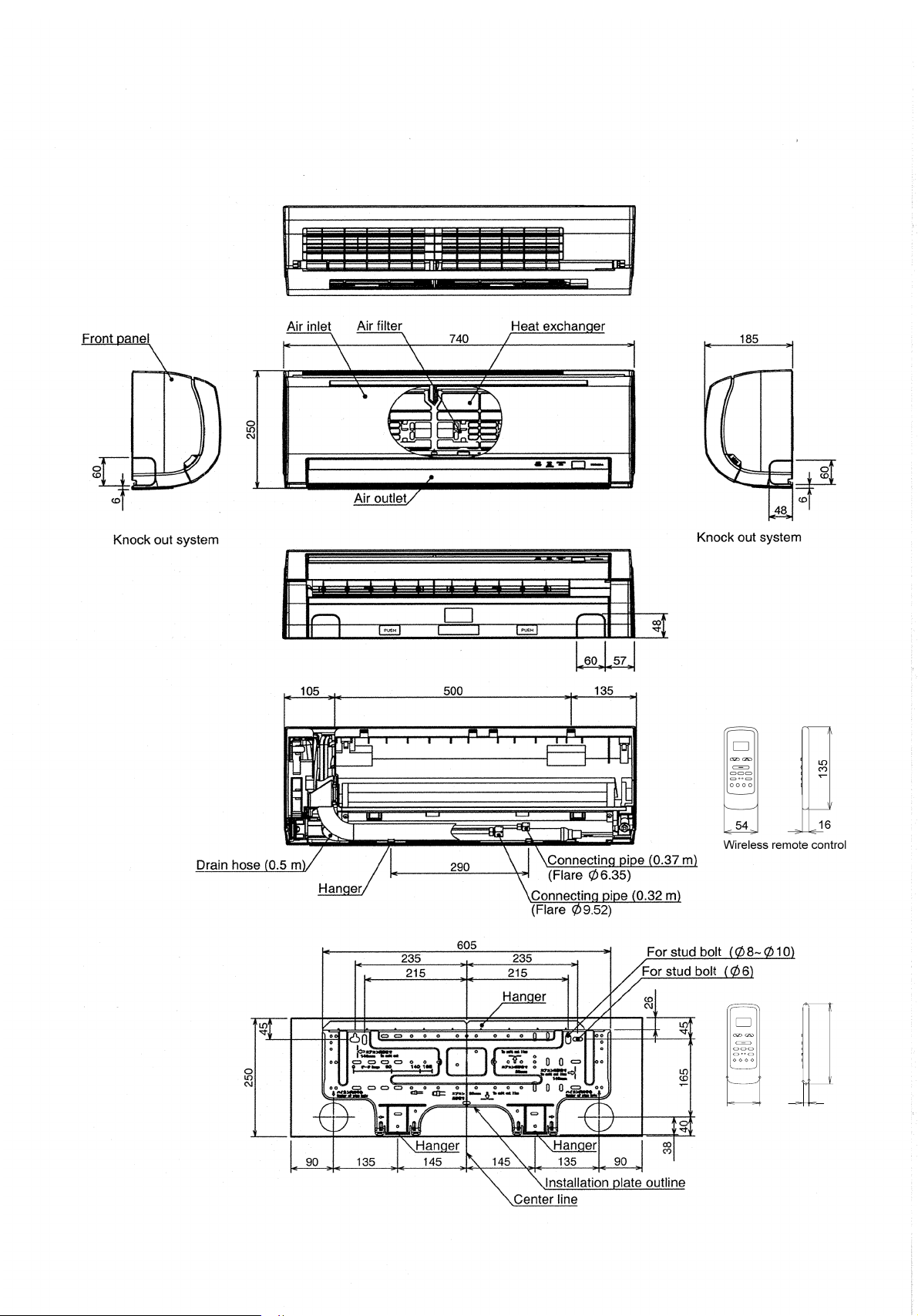
2. CONSTRUCTION VIEWS
FILE NO. SVM-08028
2-1. Indoor Unit
– 5 –
135
1654
Wireless remote control
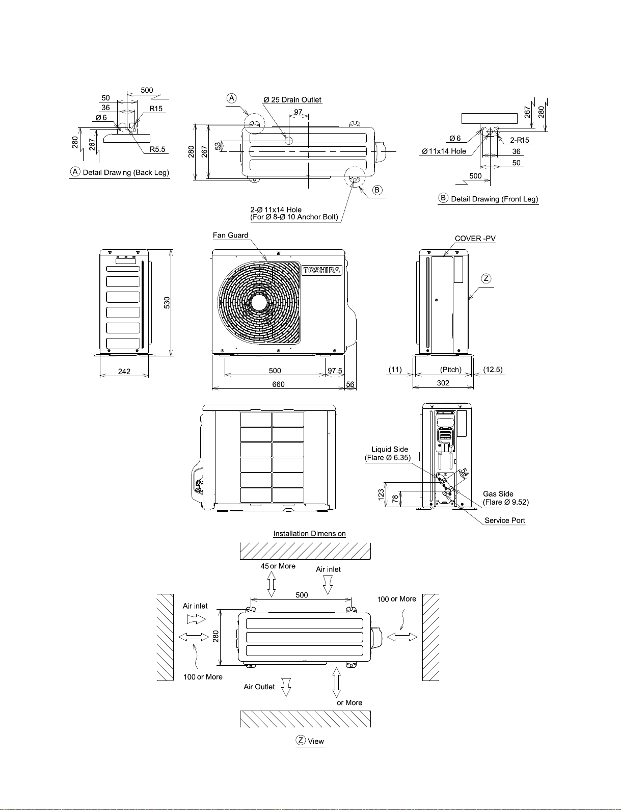
2-2. Outdoor Unit
FILE NO. SVM-08028
C
L
C
L
280
− 6 −
400
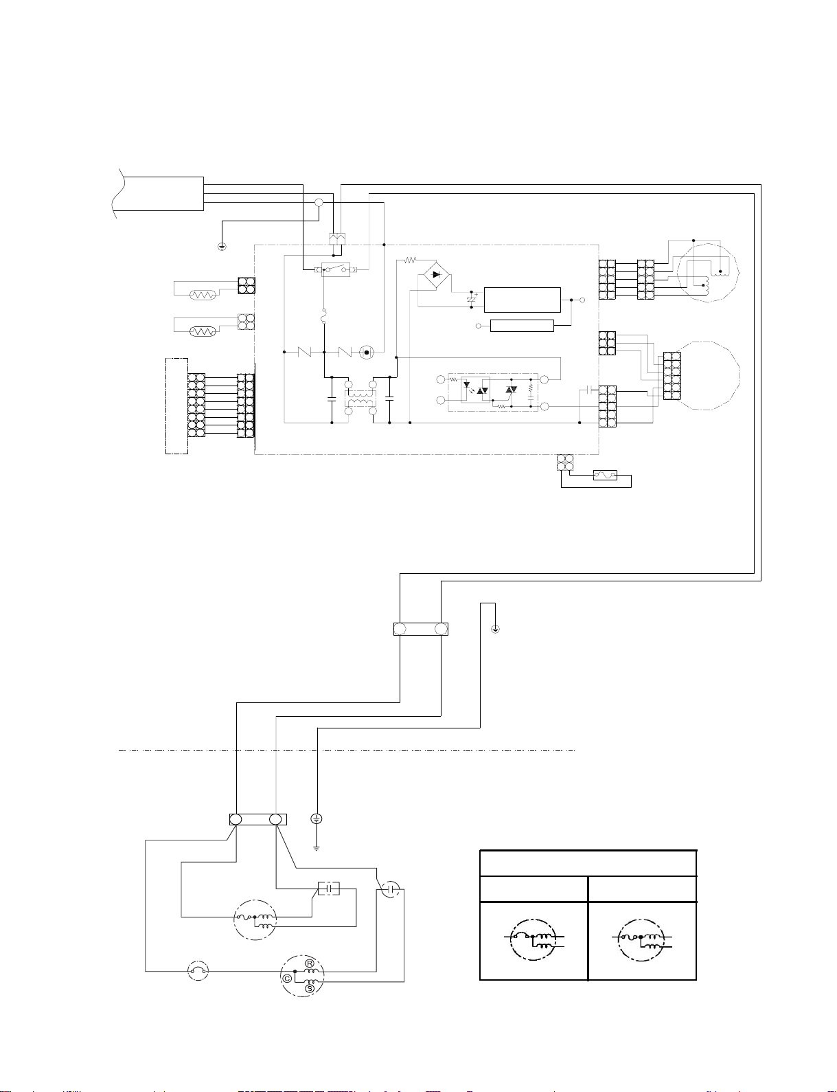
3. WIRING DIAGRAM
FILE NO. SVM-08028
SINGLE PHASE
1∅220‑240V
50Hz
BRW
BLU
GRN&YEL
Heatexchanger
Heatexchanger
Sensor(TC)
Thermosensor(TA)
CN25
1
1
2
2
3
3
4
4
5
5
6
6
7
7
8
8
andindicationparts.
Infraredraysreceiver
WP‑017
WHI
BLK
GRN&YEL
CN01
N
1
1
22
CN03
1
1
2
2
CN12
BLU
1
1
BLU
2
2
BLU
3
3
BLU
4
4
BLU
5
5
BLU
6
6
BLU
7
7
WHI
8
8
F01
6.3A
250VAC
R62
CN31
4
C25
RY01
R63
21
3
BLK
P04
3
SG01
DSA
C26
L01
4
DB01
R64
C27
Switchingpowersupply
DC5V
Voltageregulator
12V
3
4
MCU
IC03
WP‑018
1
2
CN04
22
11
PNK
DC12V
C07
PNK
Tempfuse73C
CN07
1
22
3
44
55
CN11
1
2
3
CN10
5
33
1
WHI
1
1
1
YEL
22
YEL
3
3
3
YEL
44
YEL
55
YEL
1
GRY
2
BRW
3
WHI
5
BLK
RED
1
o
1
2
3
4
565
1
2
3
4
6
Louvermotor
ACmotor
Fanmotor
TERMINAL
BLOCK
OUTDOOR
TERMINAL
BLOCK
BLK
BLK
OVERLOAD RELAY
(L)
1
FAN MOTOR
BLK
(N)
2
RED
RED
WHI
COMPRESSOR
INDOOR
TERMINAL
CHASSIS
RED
CAPACITOR
PNK
WHI
BLOCK
1
BLK
INDOOR
OUTDOOR
CAPACITOR
GRN&YEL
2
WHI
FAN MOTOR
Type "A" Type "B"
− 7 −
FILE NO. SVM-08028
4. SPECIFICATION OF ELECTRICAL PARTS
4-1. Indoor Unit
No. Parts name Type Specifications
1 Fan motor (for indoor) AFS-220-20-4AR AC Motor with 145 °C thermo fuse
2 Thermo sensor (TA-sensor) 10k at 25 C
3 Switching power supply (T01)
4 Microcontroller unit (IC30) TMP87CM40ANG-6P68
5 Heat exchanger sensor
(TC-sensor)
6 Line filter (L01) LC*SS11V-06270 27mH, 600mA
7 Bridge rectifier (DB01) DB105G 1A, 600 V
8 Capacitor (C27) EKMH401VSN470MP20S 47mF, 400 V
9 Fuse (F01) BET6.3A 6.3A, 250VAC
10 Varistor (R62, R63) SR561K14DL 560 V
11 Resistor (R64)
12 Louver motor MP24ZCT 12VDC
ST-001
RF-2TK5R6
W
W
10k at 25 C
W
5.6 , 2 W
°
°
13 Relay (Comp., RY01) G4A-1A-E-CA Rating 20A/AC250 V, 12VDC
4-2. Outdoor Unit (RAS-07S2AX-1)
Specifications
Output (Rated) 605W, 2 poles, 1 phase, 220 - 240V~, 50Hz
PH108X1C-4DZDN2 Compressor1
WLF-240-20A
(Type "A")
Fan motor (for outdoor)2
SKF-240-20B
(Type "B")
Running capacitor
3
(for fan motor)
Running capacitor
4 RS44B256U0213S
(for compressor)
DS451155NPQB
Winding resistance (Ω)
(at 20ºC) 4.84 4.40
Output (Rated) 20 W, 6 poles, 1 phase, 220 - 240 V~, 50Hz
Winding resistance (Ω)
(at 20ºC) 410 435
Output (Rated) 20 W, 6 poles, 1 phase, 220 - 240 V, 50Hz
Winding resistance (Ω)
(at 20ºC) 235.2 260.1
AC 450 V~, 1.5µF
AC 440 V~, 25µF
C-R C-S
Red-Black White-Black
Red-Black White-Black
5 Overload relay U/T : 4
JMRA99208-9102
− 8 −
.2A (80ºC), Open : 135±5ºC, Close : 69±11ºC
4-3. Outdoor Unit (RAS-09SASX-1)
z
FILE NO. SVM-08028
No. Parts name Type
Output (Rated) 780W, 2 poles, 1 phase, 220 - 240 V~, 50H
Compressor1
Fan motor (for outdoor)2
Running capacitor
3
(for fan motor)
Running capacitor
4 RS44B356U0215S
(for compressor)
5 Overload relay U/T : 6.1A (80ºC), Open : 135±5ºC, Close : 75±11ºC
QK164PBA
WLF-240-20A
(Type "A")
SKF-240-20B
(Type "B")
DS451155NPQB
LPAP960B
Winding resistance (Ω)
(at 20ºC) 3.51 3.67
Output (Rated) 20 W, 6 poles, 1 phase, 220 - 240 V~, 50Hz
Winding resistance (Ω)
(at 20ºC) 410 435
Output (Rated) 20 W, 6 poles, 1 phase, 220 - 240 V, 50Hz
Winding resistance (Ω)
(at 20ºC) 235.2 260.1
AC 450 V~, 1.5µF
AC 440 V~, 35µF
Specifications
C-R C-S
Red-Black White-Black
Red-Black White-Black
− 9 −
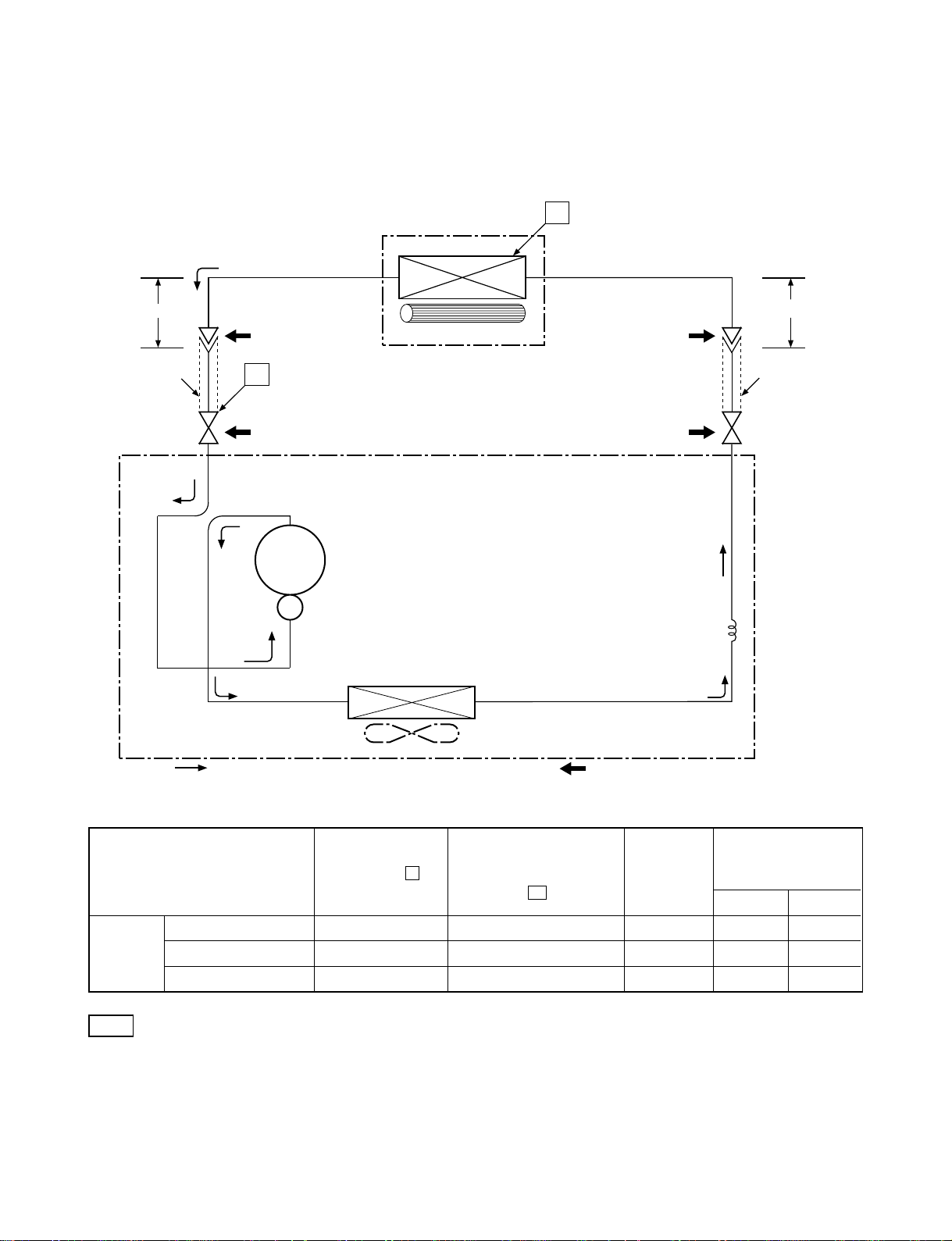
5. REFRIGERATION CYCLE DIAGRAM
5-1. RAS-07SKSX-1 / RAS-07S2AX-1
FILE NO. SVM-08028
Indoor unit
Cooling
0.39m
(Connecting pipe)
∅9.52
O.D.:9.52mm O.D.:6.35mm
Cooling
Packed valve
Cooling
P
(∅9.52)
Compressor
PH108X1C-4DZD
Heat exchanger
Cross flow fan
N2
T1
0.49m
(Connecting pipe)
∅6.35
Packed valve
(∅6.35)
Capillary tube
∅1.2x500s
xchanger
Heat e
Refrigerant
58 kg.
R22 : 0.
Cooling
Propeller fan
Outdoor unit
Mark ( ) means check points of Gas Leak.
Ambient temp.
50Hz
Standard
pressure
(MPaG)
P
Surface temp. of heat
exchanger interchanging
pipe
T1
(°C)
Fan speed
(indoor)
conditions DB/WB
(°C)
Indoor Outdoor
Standard 0.57 13.0 High 27/19 35/24
Cooling Overload 0.68 17.5 High 32/23 43/26
Low temperature 0.42 4.0 Low 21/15 21/15
Note
• Measure the heat exchanger temperature at the center of U-bend. (By means of TC sensor)
– 10 –
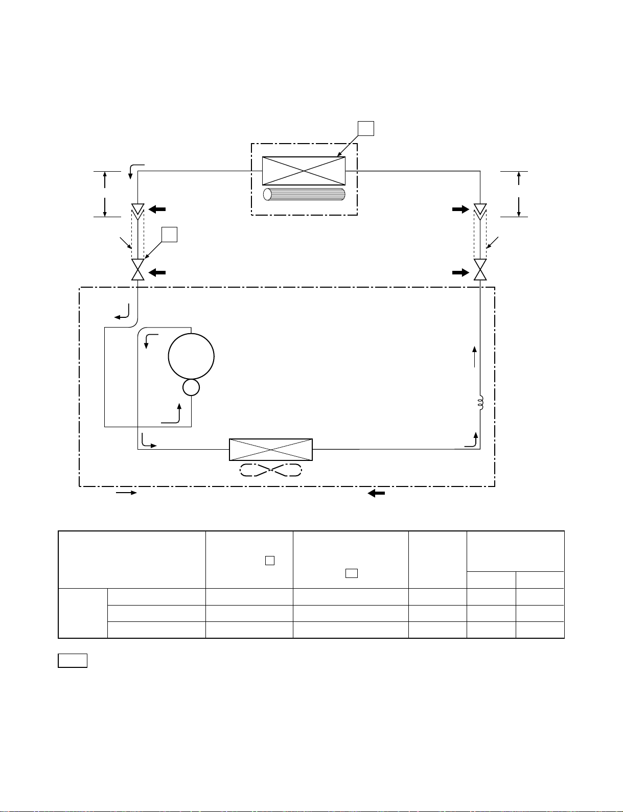
5-2. RAS-09SKSX-1 / RAS-09SASX-1
FILE NO. SVM-08028
Indoor unit
Cooling
0.39m
(Connecting pipe)
∅9.52
O.D.:9.52mm O.D.:6.35mm
Cooling
Packed valve
Cooling
P
(∅9.52)
Compressor
QK164PBA
Heat exchanger
Cross flow fan
T1
Packed valve
(∅6.35)
Capillary tube
700s
∅1.5x
0.49m
(Connecting pipe)
∅6.35
Heat exchanger
Refrigerant
0.58
Cooling
Propeller fan
Outdoor unit
R22 :
Mark ( ) means check points of Gas Leak.
kg.
Ambient temp.
50Hz
Standard
pressure
(MPaG)
P
Surface temp. of heat
exchanger interchanging
pipe
T1
(°C)
Fan speed
(indoor)
conditions DB/WB
(°C)
Indoor Outdoor
Standard 0.50 11.0 High 27/19.5 35/24
Cooling Overload 0.60 15.0 High 32/23 43/26
Low temperature 0.40 2.2 Low 21/15 21/15
Note
• Measure the heat exchanger temperature at the center of U-bend. (By means of TC sensor)
– 11 –
Heat Exchange sensor
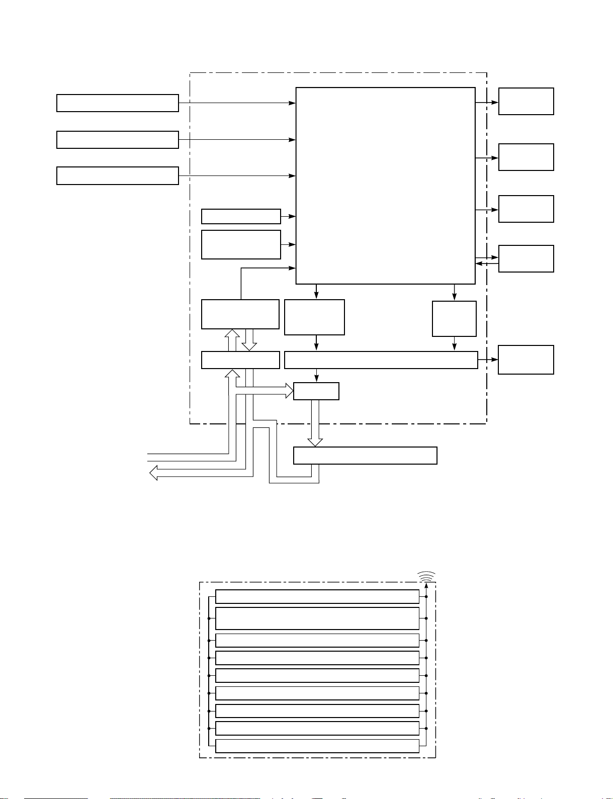
6. CONTROL BLOCK DIAGRAM
Main Unit Control Panel M.C.U.
Functions
FILE NO. SVM-08028
Operation
Display
Thermo. Sensor
Infrared Rays Signal Reciver
• Louver Control
•3-minutes Delay at Restart
for Compressor
Initiallizing Circuit
Clock Frequency
Oscillator Circuit
Power Supply
Circuit
Noise Filter Relay Driver, Louver Driver
•Motor Revolution Control
•Processing
(Temperature Processing)
•Timer
Compressor
ON/OFF
Signal
Relay
RY01
Timer
Display
Fan Only
Sign Display
Indoor Fan
Motor
Louver
ON/OFF
Signal
Louver
Motor
220-240 V~, 50Hz
REMOTE CONTROL
Compressor, Outdoor Fan Motor
Infrared Rays
Remote Control
Operation (START/STOP)
Operation Mode Selection
AUTO, COOL, DRY, AUTO FAN
Temperature Setting
Fan Speed Selection
ON TIMER Setting
OFF TIMER Setting
Louver Auto Swing
Louver Direction Setting
ECO
− 12 −
7. OPERATION DESCRIPTION
FILE NO. SVM-08028
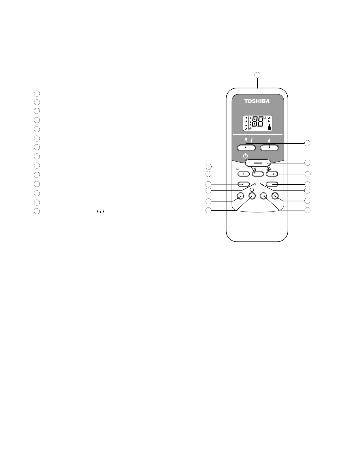
7-1. Remote control
7-1-1. Function of Push Putton
Infrared signal emitter
1
2
Set louver button (FIX)
Auto Louver button (SWING)
3
Mode select button (MODE)
4
Reset button (RST)
5
On timer button (ON)
6
7
Off timer button (OFF)
Reserve button (SET)
8
Cancel button (CLR)
9
10
Check button (CHK)
11
ECO button (ECO)
12
Fan speed button (FAN)
13
Start/Stop button (START/STOP)
14
Temperature button ( )
1
MODE
AUTO
COOL
AUTO FAN
2
DRY
SWING
TEMP.
Hr.ON OFF
TEMP.
START/STOP
3
MODE
4
5
6
RST
TIMER
ON OFF SET CLR
7
FIX
CHK
FAN
AUTO
B
QUIET
14
13
FAN
12
ECO
11
10
9
8
− 13 −
FILE NO. SVM-08028
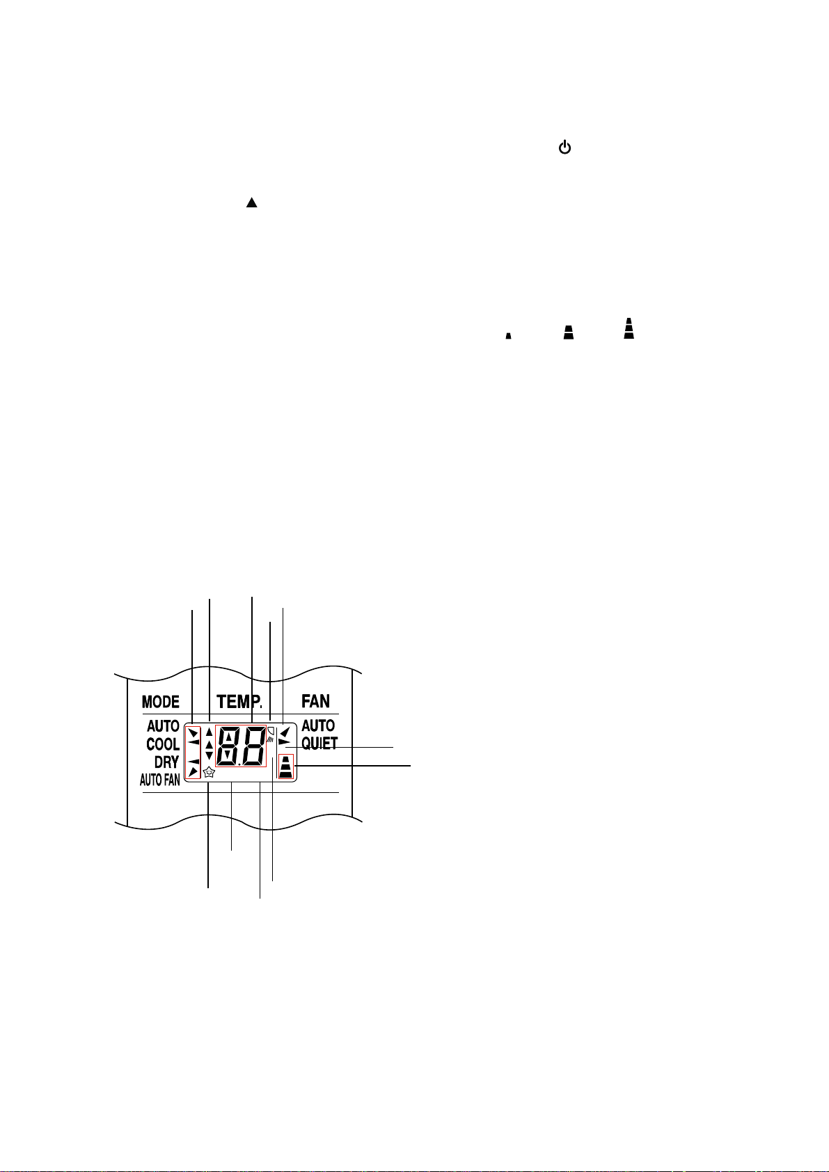
7-1-2. Display of Remote Control
All indications, except for the clock time indicator, are displayed by pressing the button.
1. Transmission mark
This transmission mark
remote controller transmits signals to the indoor
unit.
indicates when the
2. Mode indicator
Indicates the current operation mode.
(AUTO, COOL, DRY and AUTO FAN)
3. Temperature indicator
Indicates the temperature setting.
(17°C to 30°C)
4. ECO indicator
Indicates when the ECO is in activated.
Press the ECO button to start and press it again
to stop operate.
5. A, B change indicator remote controller
When the remote controller switching function is
set, "B" appears in the remote controller display
(When the remote controller seting is "A", there is
no indication at this position.)
1
3
2
7
6
6. Swing
Indicate when louver is swing.
Press swing button to start the swing operation
and press it again to stop the swing operation.
7. FAN speed indicator
Indicates the selected fan speed.
AUTO, QUIET or three fan speed levels
( LOW , MED , HIGH can be shown.
Indicate Auto will be appear with Dry operation
only.
8. ON/OFF TIMER indicator
Indicates when the ON/OFF TIMER operation.
(ON TIMER [Hr. ON], OFF TIMER [OFF]).
•
•
Hr.ON OFF
•
4
•
•
•
•
B
•
•
•
•
7
7
8
5
8
− 14 −
7-2. Outline of Air Conditioner Control
FILE NO. SVM-08028
This is a fixed capacity type air conditioner, which uses
a AC motor for an indoor fan. The AC motor drive
circuit is mounted in the indoor unit. And electrical
parts which operate the compressor and the outdoor
fan motor, are mounted in the outdoor unit.
The air conditioner is mainly controlled by the indoor
unit controller. The controller operates the indoor fan
motor based upon commands transmitted by the
remote control and transfers the operation commands
to the outdoor unit controller.
The outdoor unit receives operation commands from
the indoor unit, and operates the outdoor fan motor
and the compressor.
(1) Role of indoor unit controller
The indoor unit controller receives the operation
commands from the remote control and executes
them.
• Temperature measurement at the air inlet of the
indoor heat exchanger by the indoor
temperature sensor
• Temperature measurement of the indoor heat
exchanger by the heat exchanger sensor
• Louver motor control
• Indoor fan motor operation control
• LED display control
• Transferring of operation commands to the
outdoor unit
• Receiving of information of the operation status
and judging of the information or indication of
error
(2) Role of outdoor unit controller
The outdoor unit controller receives the operation
commands from the indoor controller and
executes them.
• Compressor operation
control
• Operation control of
outdoor fan motor
Operations according
to the commands
from the indoor unit
• Turning off the compressor and outdoor fan
when the outdoor unit receives the shutdown
command
7-2-1. Louver control
(1) Vertical air flow louver
Position of veritcal air flow louver is automatically
controlled according to the operation mode.
Besides, position of vertical air flow louver can be
arbitrarily set by pressing [FIX] button.
The louver position which is set by [FIX] button is
stored in the microcomputer, and the louver is
automatically set at the stored position for the next
operation.
(2) Swing
If [SWING] button is pressed when the indoor unit
is in operation, the vertical air flow louver starts
swinging. When [FIX] button is pressed, it stops
swinging.
7-2-2. Indoor Fan Control
The operation controls the fan speed at indoor unit
side. The indoor fan (cross flow fan) is operated by
the phase control induction motor. The fan rotates in 3
stages in MANUAL model, and in 5 stages in AUTO
mode, respectively. (Table 7-2-1)
1) When setting the fan speed to L, M or H on
the remote controller, the operation is performed
with the constant speed shown in Fig. 7-2-1.
Fig (7-2-1)
Indication
L
M
H
Fan speed
Low
Med
High
2) When setting the fan speed to AUTO on the remote
controller, revolution of the fan motor is controlled
to the fan speed level shown in Table 1 according to
the setup temperature, room temperature, and heat
exchanger temperature.
3) When setting the fan speed to QUIET on the remote
controller, revolution of the fan motor is controlled
to the fan speed level is L-.
Table 7-2-1 Indoor fan and air flow rate
OPERATION
MODE
RAS-07SKSX-1
Model
RAS-09SKSX-1
Cool
Dry
fan speed (rpm)
Air flow (m
fan speed (rpm)
Air flow (m3/h)
3
/h)
Fan speed level
UH H M+ M L+ L L- UL SUL
UH H M+ M L+ L L- UL SUL
1300 1300 1300 1300 1250 1150 1100 950 950 900 800 750 700 650 500
540 540 540 540 510 470 440 370
1350 1350 1350 1300 1250 1180 1140 1000 980 980 900 800 750 700 550
560 560 560 540 510 500 460 400
370 350 300 270 250 220 150
390 390 350 300 270 250 180
− 15 −
FILE NO. SVM-08028
7-3. Description of Operation Mode
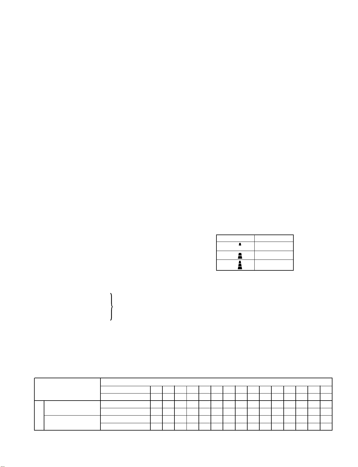
(1) When turning on the breaker, the operation lamp
blinks. This means that the power is on (or the
power supply is cut off.)
(2) When pressing [ ] button on the
remote control, receiving beep sounds from the
indoor unit, and the next operation is performed
together with opening the vertical air flow louver.
(3) Once the operation mode is set, it is memorized in
the microcomputer so that the previous operation
can be effected thereafter simply by pressing
[ ] button.
7-3-1. Fan only operation
([MODE] button on the remote control is set
to the fan only operation.)
(1) When [FAN] button is set to AUTO, the indoor fan
motor operates as shown in Fig. 7-3-1. When
[FAN] button is set to LOW, MED, or HIGH
the motor operates with a constant air flow.
°C
7-3-2. Cooling operation
([MODE] button on the remote control is set
to the cooling operation.)
(1) The compressor, outdoor fan and operation
display lamp are controlled as shown in
Fig. 7-3-2.
°C
ON ON
OFF OFF ON
Compressor
Outdoor fan
-
(Room temp.) (Preset temp.)
Preset
temp.
0.5
0
Fig. 7-3-2
display
OPERATION
+3
+2.5
+2
+1.5
+1
+0.5
(Room temp.) − (Preset temp.)
Preset
temp.
0
(Preset temp.: 24 °C)
NOTE1 : *1 : Fan speed = (M + - L) x 3/4 + L
*2 : Fan speed = (M + - L) x 2/4 + L
*3 : Fan speed = (M + - L) x 1/4 + L
(Linear approximation
from M+ and L)
NOTE2 : ECO operation can not be set.
Fig. 7-3-1 Setting of air flow [FAN:AUTO]
M+
*1
*2
*3
(2) When [FAN] button is set to AUTO, the indoor fan
motor operates as shown in Fig. 7-3-5. When
[FAN] button is set to LOW, MED or HIGH
the motor operates with a constant air flow.
°C
(Room temp.) − (Preset temp.)
Preset
temp.
+3
+2.5
+2
+1.5
+1
+0.5
0
-0.5
M+
*1
*2
*3
NOTE1 : *1 : Fan speed = (M + - L) x 3/4 + L
*2 : Fan speed = (M + - L) x 2/4 + L
*3 : Fan speed = (M + - L) x 1/4 + L
(Linear approximation
from M+ and L)
Fig. 7-3-3 Setting of air flow [FAN:AUTO]
− 16 −
FILE NO. SVM-08028
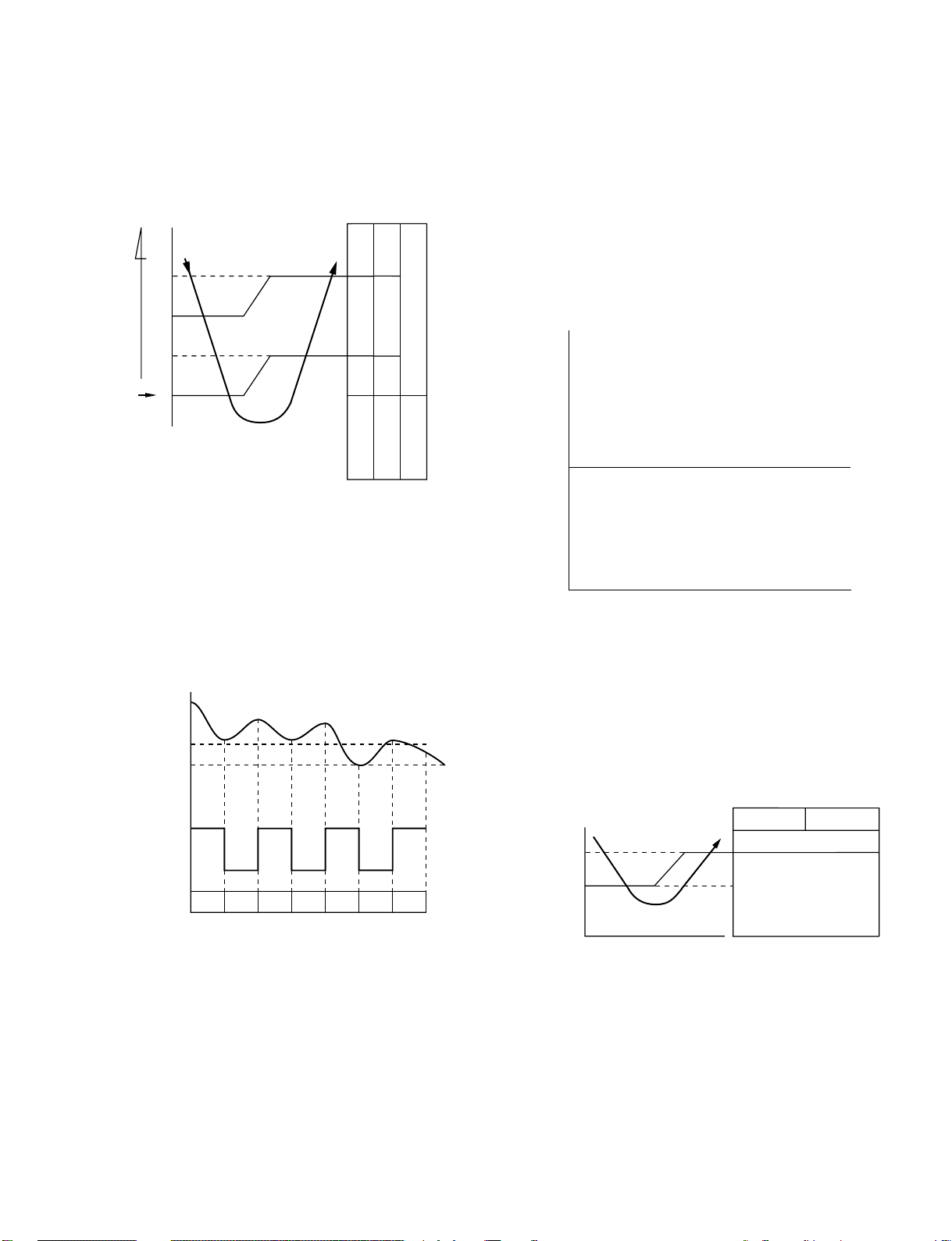
7-3-3. Dry operation
([MODE] button on the remote control is set
to the dry operation.)
(1) The compressor, outdoor fan and operation
display on the remote control are controlled
as shown in Fig. 7-3-4.
°C
ON:6min.
OFF:4min.
ON:6min.
OFF:4min.
ON:5min.
ON:5min.
OFF:5min.
OFF
OFF
Compressor
ON
OFF:5min.
Outdoor fan
-
(Room temp.) (Preset temp.)
Preset
temp.
+3
+2
+1
0
Fig. 7-3-4
display
OPERATION
(1) One of 2 operations (Cooling or Fan only)
is selected according to difference between the
preset temperature and the room temperature at
which the automatic operation has started, as
shown in Fig. 7-3-6. The Fan only operation
continues until the room temperature reaches a
level at which another mode is selected.
(2) Temporary Auto
When the [RESET] button on the indoor unit
is pushed, the preset temperature is fixed at 24°C
and the indoor unit is controlled as shown in
Fig. 7-3-6.
°C
Cooling operation
0
-
Fan only operation
(2) The microcontroller turns the compressor on and
off at the regular intervals (4 to 6 minutes). While
the compressor is turning off, the indoor fan motor
operates in the SUPER LOW position.
The pattern of operation depending on the relation
between room temperature and preset
temperatures is shown in Fig. 7-3-5.
Room temp.
Preset temp.+1
Preset temp.
Compressor
Outdoor fan
Indoor fan
ON ON ON ON
OFF OFF OFF
L *SL SLLL SL L
*
Super Low
Fig. 7-3-5
(3) [FAN] button on the remote control is set to AUTO
only.
(Room temp.) (Preset temp.)
Fig. 7-3-6
7-4. Low-Temperature Limit Control
The microcontroller detects the indoor heat exchanger
temperature to prevent the indoor heat exchanger from
freezing.
The compressor and outdoor fan motor are controlled
as shown in Fig. 7-4-1
Heat exchanger
temperature
(°C)
5
2
Fig. 7-4-1
Compressor Outdoor fan
ON
Less than 2°C continues
for 5 minutes
OFF
(4) The ECO operation cannot be set.
7-3-4. Automatic operation
([MODE] button on the remote control is set
to the automatic operation.)
− 17 −
 Loading...