

Toshiba RAS-09 12EK Series, RAS-09 12EA Series Installation Manual
ENGLISH
ESPAÑOL
FRANÇAIS
Indoor unit
RAS-09, 12EK Series
Outdoor unit
RAS-09, 12EA Series
AIR CONDITIONER (SPLIT TYPE)
INSTALLATION MANUAL
1110251291-2
1110251291-2 EN.indd 11110251291-2 EN.indd 1 12/13/13 4:59 PM12/13/13 4:59 PM

CONTENTS
EN
CONTENIDOS
ES
SOMMAIRE
FR
DIMENSIONS ...............................................................................................1
SYSTEM REQUIREMENTS .........................................................................3
Piping (Field supplied) ..............................................................................3
Power Wiring ............................................................................................3
PRECAUTIONS FOR SAFETY ....................................................................4
INSTALLATION DIAGRAM OF INDOOR AND OUTDOOR UNITS ............6
Field Supplied Installation Parts ...............................................................6
OUTDOOR UNIT ..........................................................................................7
Installation Location ..................................................................................7
Precautions about Installation in Regions with Snowfall and
Cold Temperatures ...................................................................................7
Refrigerant Piping Connection ..................................................................7
Wiring Connection ....................................................................................7
Electrical Work ..........................................................................................8
INDOOR UNIT ..............................................................................................8
Installation Location ..................................................................................8
Cutting a Hole and Mounting the mounting Plate .....................................8
Wiring Connection ....................................................................................9
Piping and Drain Hose Installation ...........................................................9
Indoor Unit Fixing ...................................................................................10
Drainage ................................................................................................. 11
Remote Control A-B Selection ................................................................ 11
EVACUATING ............................................................................................ 11
Evacuating ............................................................................................. 11
OTHER .......................................................................................................12
Gas Leak Test .........................................................................................12
Test Operation .......................................................................................12
Auto Restart Setting ..............................................................................12
Troubleshooting (Check Point) ..............................................................12
DIMENSIONES ............................................................................................1
REQUISITOS DE INSTALACIÓN ................................................................3
Tuberías (Suministradas en el campo) .....................................................3
Cableado de alimentación ........................................................................3
PRECAUCIONES DE SEGURIDAD ............................................................4
DIAGRAMA DE INSTALACIÓN DE LA UNIDAD INTERIOR Y EXTERIOR
..6
Piezas de instalación suministradas en el campo ....................................6
UNIDAD EXTERIOR ....................................................................................7
Locación de Instalación ............................................................................7
Precauciones sobre Instalación en Regiones con Nieve y
Temperaturas Frías ..................................................................................7
Conección de la Tubería Refrigerante ......................................................7
Conección de Cables ...............................................................................7
Trabajo Eléctrico ......................................................................................8
UNIDAD INTERIOR .....................................................................................8
Locación de Instalación ............................................................................8
Corte de un Orifi cio y Montaje de la Placa de Montaje ............................8
Conección de Cables ...............................................................................9
Instalación de Tubería y Tubo de Desagüe .............................................9
Instalación de la Unidad Interior .............................................................10
Drenaje ..................................................................................................11
Selección A-B del control remoto ...........................................................11
EVACUACIÓN ............................................................................................ 11
Evacuación ............................................................................................11
OTRO .........................................................................................................12
Prueba de Fugas ....................................................................................12
Prueba de Operación ............................................................................12
Ajuste de Reinicio Automático ...............................................................12
Resolución de problemas (Punto de chequeo) ......................................12
DIMENSIONS ...............................................................................................1
CONFIGRATION SYSTEME REUQISE .......................................................3
Tuyauterie (Fournie sur chantier) .............................................................3
Câblage d’alimentation .............................................................................3
MESURES DE SÉCURITÉ ...........................................................................4
PLAN D’INSTALLATION DES UNITÉS INTÉRIEURE ET EXTÉRIEURE ..6
Pièces fournies pour l’installation .............................................................6
UNITÉ EXTÉRIEURE ...................................................................................7
Lieu d’Installation ......................................................................................7
Précautions à prendre pour l’installation dans les régions sujettes aux
chutes de neige et aux températures froides ...........................................7
Connexion du Tuyau Réfrigérant ..............................................................7
Connexion des Câbles .............................................................................7
Travaux Electriques .................................................................................8
UNITÉ INTÉRIEURE ....................................................................................8
Lieu d’Installation ......................................................................................8
Ouverture du trou et montage de la plaque de montage ..........................8
Connexion des Câbles .............................................................................9
Installation de la Conduite et du Tuyau de Purge ....................................9
Installation de l’Unité Intérieure ..............................................................10
Drainage ................................................................................................11
Sélection de télécommande A-B ............................................................11
EVACUATION ............................................................................................ 11
Evacuation ............................................................................................. 11
AUTRE .......................................................................................................12
Test de Fuite Gaz ...................................................................................12
Opération du Test ..................................................................................12
Réglage de la Remise en Marche Automatique ....................................12
Depannage (Elements a Verifi er) ..........................................................12
1110251291-2 EN.indd 21110251291-2 EN.indd 2 12/13/13 4:59 PM12/13/13 4:59 PM
EN
SI
1
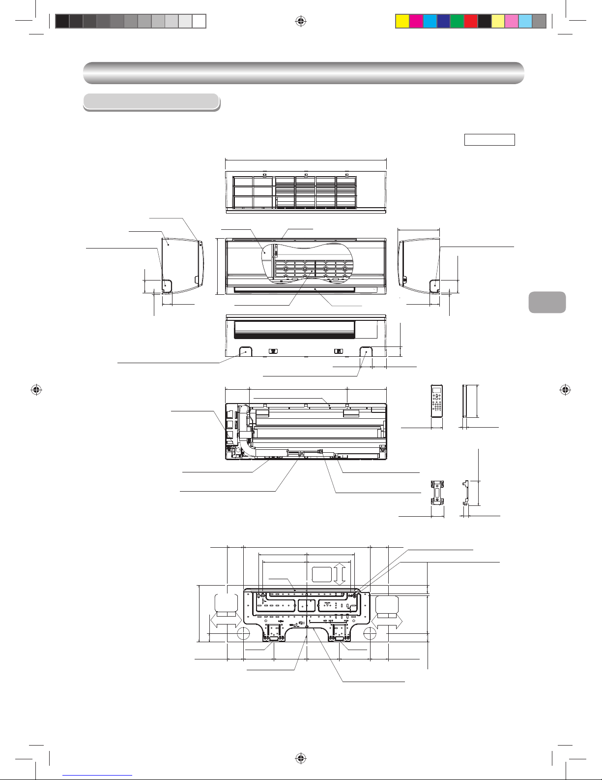
DIMENSIONS
DIMENSIONS
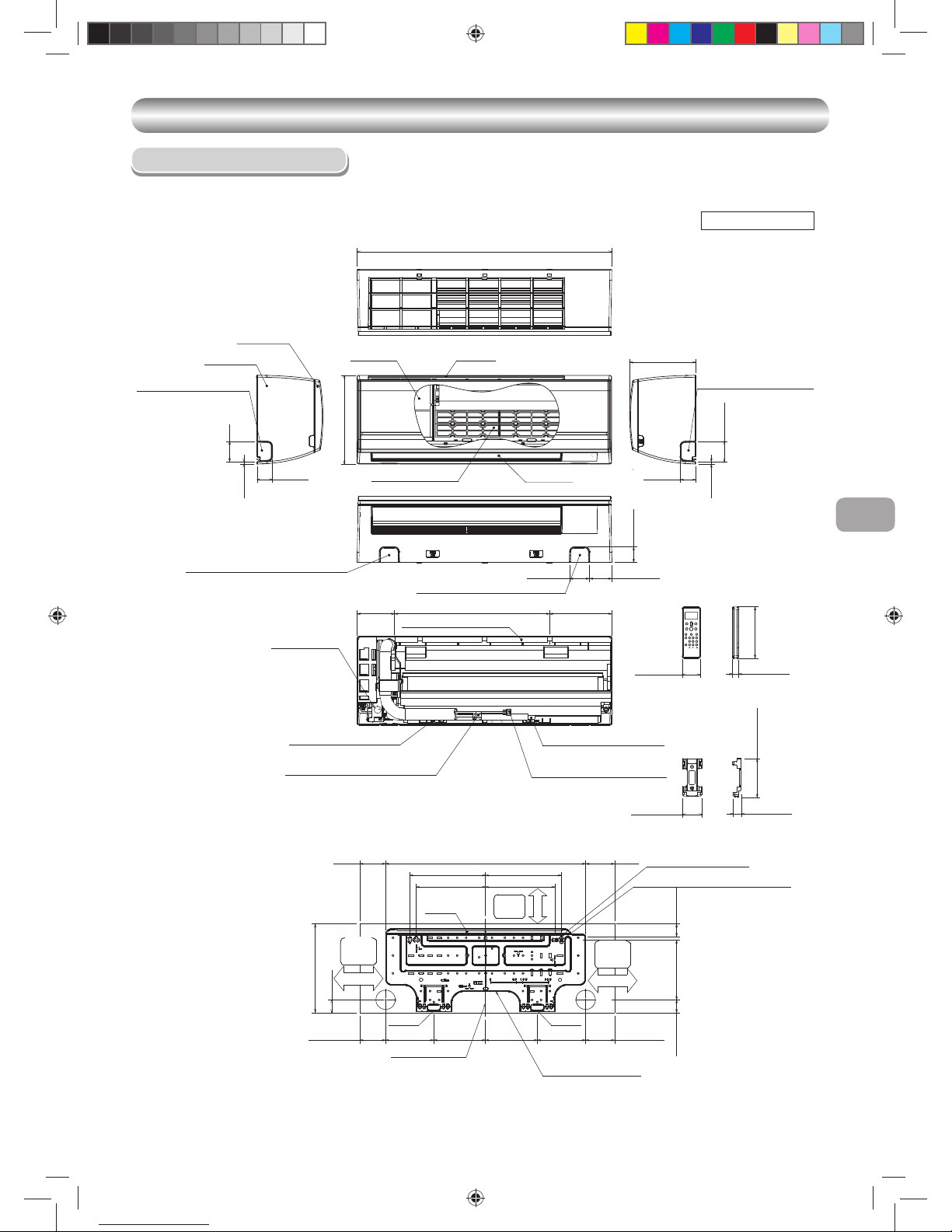
Indoor Unit
Unit : Inch (mm)
2-15/32(63)
7-15/32(190)
6-5/16(161) 5-1/2(150)
10-13/16(275)
1-9/16(40)
1-9/16(40)
1-3/4(45)
7-19/32(193)18-7/8(480)
2-7/16(62) 2-11/16(69)
1-7/8(48)
2-15/32(63)
9/32(7)
1-7/8(48)
4-9/16(116)
10-25/32(275)
1-7/8(48)
9/32(7)
24-7/16(621)
8-1/16(205)
31-1/8(790)
8-7/16(215)
9-1/4(235)
9-1/4(235)
8-7/16(215)
6-5/16(161)5-1/2(150)
Front panel
Knockout for leftward piping
Air fi lter Air inlet
Heat exchanger
Knockout for rightward piping
Knockout for bottom leftward piping
Knockout for bottom rightward piping
Installation plate hanger
Conduit hole
(Ø7/8(22) hole)
Connecting pipe (18-5/8(0.40m))
(Flare Ø1/4(6.35))
Installation plate hanger
Connecting pipe (13-25/32(0.35m))
(Flare Ø3/8(9.52))
Wireless remote controller
Drain hose (19-11/16(0.50m))
Remote controller holder
3-5/16(84.5)
3-5/16(84.5)
3-5/16(84.5)3-5/16(84.5)
Hanger
Hanger
Hanger
Center line
Installation plate outline
Minimum
distance
to wall
Minimum
distance
to wall
Minimum
distance
to wall
6-11/16(170)or more
6-11/16(170)or more
2-9/16(65)or more
Grille Inlet
Air outlet
For stud bolt (Ø2-1/4(6))
For stud bolt (Ø5/16(8)~Ø13/32(10))
31/32 (26)
3/4 (19)
2-15/32 (63)
2-3/16 (56)
4-29/32 (125)
6-3/4 (157)
1110251291-2 EN.indd 11110251291-2 EN.indd 1 12/13/13 4:59 PM12/13/13 4:59 PM

EN
SI
3
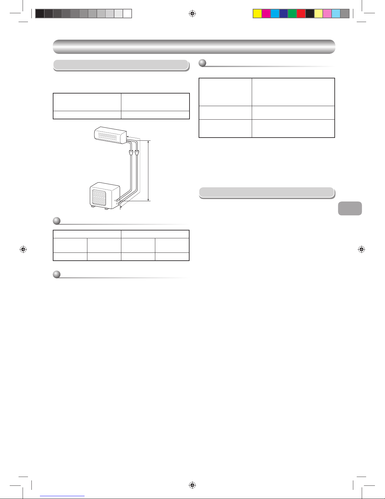
Piping (Field supplied)
• Minimum refrigerant line length between the outdoor unit and indoor unit is
6.6ft. (2m).
• Maximum pipe lengths
SYSTEM REQUIREMENTS
SYSTEM REQUIREMENTS
Allowable
Pipe length T
(ft (m))
Height difference
(Indoor – Outdoor H)
(ft (m))
66 (20) 33 (10)
Refrigerant pipe sizes
HT
Liquid side Gas side
Outer Diameter
In. (mm)
Thickness
In. (mm)
Outer diameter
In. (mm)
Thickness
In. (mm)
Ø1/4 (6.35) 0.03 (0.8) Ø3/8 (9.52) 0.03 (0.8)
Insulation
Both lines need to be insulated. Use a minimum 5/16 in (8mm) wall
thickness.
Refrigerant charge
Unit : ft (m)
Refrigerant charge
Length of refrigerant Pipe
connected to Indoor/
outdoor unit
Additional refrigerant
6.6-50
(2-15m)
None
50-66
(15-20m)
Add 0.22oz/ft (20g/m) of
Refrigerant for piping that exceeds
50ft (15m) up to 66ft (20m)
* Caution during addition of refrigerant
Max. amount of additional refrigerant is 0.22 lbs (100g).
Charge the system accurately. Overcharging may damage the
compressor.
* Minimum refrigerant pipe is 6.6ft (2m).
Using pipe shorter than that may cause a malfunction of the compressor
or other components.
Power Wiring
The main power is supplied to the outdoor unit. The fi eld supplied
connecting cable from the outdoor unit to indoor unit consists of three (3)
wires and provides the power for the indoor unit. Two wires are high voltage
AC power and one is a ground wire.
Consult your local building codes and the NEC (National Electrical Code) or
CEC (Canadian Electrical Code) for special requirements.
All wires must be sized per NEC or CEC and local codes. Use Electrical
Data table MCA (minimum circuit amps) and MOCP (maximum over current
protection) to correctly size the wires and the disconnect fuse or breakers
respectively.
Only copper conductors with a minimum 300 volt rating and 2/64--inch thick
insulation must be used.
Interconnecting cable between FCU and CDU must be a minimum AWG14.
1110251291-2 EN.indd 31110251291-2 EN.indd 3 12/13/13 5:00 PM12/13/13 5:00 PM

4
PRECAUTIONS FOR SAFETY
PRECAUTIONS FOR SAFETY
New refrigerant air conditioner installation
CAUTION
• THIS AIR CONDITIONER USES THE HFC REFRIGERANT (R410A), WHICH DOES NOT DESTROY THE OZONE LAYER.
R410A refrigerant is affected by impurities such as water and oils because the pressure of R410A refrigerant is approx. 1.6 times of refrigerant R22.
ALSO NEW OILS ARE USED WITH R410A, THUS ALWAYS USE NEW REFRIGERANT PIPING AND DO NOT ALLOW MOISTURE OR DUST TO
ENTER THE SYSTEM.
To avoid mixing refrigerant and refrigerant machine oil, the sizes of charging port on the main unit is different than those used on R22 machines and
different tools will be required.
• EQUIPMENT DAMAGE HAZARD
Failure to follow this caution may result in equipment damage or improper operation.
Do not bury more than 36 in. (914 mm) of refrigerant pipe in the ground. If any section of pipe is buried, there must be a 6 in. (152 mm) vertical rise to
the valve connections on the outdoor units. If more than the recommended length is buried, refrigerant may migrate to the cooler buried section during
extended periods of system shutdown. This causes refrigerant slugging and could possibly damage the compressor at start-up.
DANGER
• FOR USE BY QUALIFIED PERSONS ONLY.
• TURN OFF MAIN POWER SUPPLY BEFORE ATTEMPTING ANY ELECTRICAL WORK. MAKE SURE ALL POWER SWITCHES ARE OFF.
FAILURE TO DO SO MAY CAUSE ELECTRIC SHOCK.
• CONNECT THE CONNECTING CABLE CORRECTLY. IF THE CONNECTING CABLE IS CONNECTED WRONGLY, ELECTRIC PARTS MAY BE
DAMAGED.
• CHECK THAT THE EARTH GROUND WIRE IS NOT BROKEN OR DISCONNECTED BEFORE INSTALLATION.
• DO NOT INSTALL THE UNIT NEAR CONCENTRATIONS OF COMBUSTIBLE GAS OR GAS VAPORS.
FAILURE TO FOLLOW THIS INSTRUCTION CAN RESULT IN FIRE OR EXPLOSION.
• TO PREVENT OVERHEATING THE INDOOR UNIT AND CAUSING A FIRE HAZARD, PLACE THE UNIT WELL AWAY (MORE THAN 2 M) FROM
HEAT SOURCES SUCH AS RADIATORS, HEATERS, FURNACE, STOVES, ETC.
• WHEN RELOCATING THE AIR CONDITIONER, BE VERY CAREFUL NOT TO MIX THE SPECIFIED REFRIGERANT (R410A) WITH ANY OTHER
GASEOUS BODY INTO THE REFRIGERATION CYCLE. IF AIR OR ANY OTHER GAS IS MIXED WITH THE REFRIGERANT, THE GAS PRESSURE
IN THE REFRIGERATION CYCLE BECOMES ABNORMALLY HIGH AND IT RESULTINGLY CAUSES BURST OF THE PIPE AND INJURIES ON
PERSONS.
• IN THE EVENT OF REFRIGERANT LEAKAGE DURING INSTALLATION, ALLOW FRESH AIR INTO THE ROOM IMMEDIATELY. IF THE
REFRIGERANT GAS IS HEATED BY FIRE OR OTHER MEAN, IT GENERATES POISONOUS GAS.
Installing, staring up, and servicing air-conditioning equipment can be hazardous due to system pressures, electrical components, and equipment location
(roofs, elevated structures, etc.).
Only trained, qualifi ed installers and service mechanics should install, start-up, and service this equipment.
Untrained personnel can perform basic maintenance functions such as replacing fi lters. All other operations should be performed by trained service
personnel.
When working on the equipment, observe precautions in the literature and on tags, stickers, and labels attached to the equipment.
Follow all safety codes, Wear safety glasses and work gloves. Keep quenching cloth and fi re extinguisher nearby when brazing. Use care in handling,
rigging, and setting bulky equipment.
Read these instructions thoroughly and follow all warnings or cautions included in literature and attached to the unit. Consult local building codes and
National Electrical Code (NEC) for special requirements. Recognize safety information. This is the safety-alert symbol å. When you see this symbol on
the unit and in instructions or manuals, be alert to the potential for personal injury. Understand these signal words: DANGER, WARNING, and CAUTION.
These words are used with the safety-alert symbol.
DANGER identifi es the most serious hazards which will result in severe personal injury or death. WARNING signifi es hazards which could result in personal
injury or death. CAUTION is used to identify unsafe practices which would result in minor personal injury or product and property damage. NOTE is used to
highlight suggestions which will result in enhanced installation, reliability, or operation.
• Before installation, please read these precautions for safety carefully.
• Be sure to follow the precautions provided here to avoid safety risks. The symbols and their meanings are shown below.
1110251291-2 EN.indd 41110251291-2 EN.indd 4 12/13/13 5:00 PM12/13/13 5:00 PM
EN
SI
5
CAUTION
• Exposure of unit to water or other moisture before installation could result in electric shock. Do not store it in a wet basement or expose to rain or water.
• After unpacking the unit, examine it carefully for possible damage. Report any damages to your distributor.
• Do not install in a place that can increase the vibration of the unit. Do not install in a place that can amplify the noise level of the unit or where noise and
discharged air might disturb neighbors.
• Please read this installation manual carefully before installing the unit. It contains further important instructions for proper installation.
• This appliance must be connected to the main power supply by means of a circuit breaker depending on the place where the unit is installed. Failure to do
so may cause electrical shock.
• Follow the instructions in this installation manual to arrange the drain pipe for proper drainage from the unit. Ensure that drained water is discharged.
Improper drainage can result in water leakage, causing water damage to furniture.
• Tighten the fl are nut with a torque wrench using the prescribed method. Do not apply excess torque. Otherwise, the nut may crack after a long period of
usage and it may cause the leakage of refrigerant.
• Wear heavy gloves for installation work. Failure to do so may cause personal injury when handling parts with sharp edges.
• Do not touch the air intake section or the aluminum fi ns of the outdoor unit. It may cause injury.
• Do not install the outdoor unit in a place which can be a nest for small animals. Small animals could enter and contact internal electrical parts, causing a
failure or fi re.
• Request the user to keep the place around the unit tidy and clean.
• Make sure to conduct a trial operation after the installation work, and explain how to use and maintain the unit to the customer in accordance with the
manual. Ask the customer to keep the operation manual along with the installation manual.
• The manufacturer shall not assume any liability for the damage caused by not observing the description of this manual.
WARNING
• ELECTRICAL SHOCK HAZARD
Failure to follow this warning could result in personal injury or death.
Main electrical disconnect switch must be in the OFF position before installing, modifying, or servicing the system. There may be more than one disconnect
switch. Lock out and tag switch with a suitable warning label.
• Never modify this unit by removing any of the safety guards or bypassing any of the safety interlock switches.
• Installation work must be performed by qualifi ed personnel only.
• Specifi ed tools and pipe parts for model R410A are required, and installation work must be done in accordance with the manual. HFC type refrigerant
R410A has 1.6 times more pressure than that of conventional refrigerant (R22). Use the specifi ed pipe parts, and ensure correct installation, otherwise
damage and/or injury may be caused. At the same time, water leakage, electrical shock, and fi re may occur.
• Be sure to install the unit in a place that can suffi ciently bear its weight. If the load bearing of the unit is not enough, or installation of the unit is improper,
the unit may fall and result in injury.
• Electrical work must be performed by trained, qualifi ed installers and service mechanics in accordance with the code governing such installation work,
internal wiring regulations, and the manual. A dedicated circuit and the rated voltage must be used. Insuffi cient power supply or improper installation
may cause electrical shock or fi re.
• Use a cabtyre cable to connect wires in the indoor/outdoor units. Midway connection is not allowed. Improper connection or fi xing may cause a fi re.
• Wiring between the indoor unit and outdoor units must be well shaped so that the cover can be fi rmly placed. Improper cover installation may cause
increased heat, fi re, or electrical shock at the terminal area.
• Be sure to use only approved accessories or specifi ed parts. Failure to do so may cause the unit to fall, water leakage, fi re or electrical shock.
• After the installation work, ensure that there is no leakage of refrigerant gas. If the refrigerant gas leaks out of the pipe into the room and is heated by
fi re or something else from a fan heater, stove or gas range, it can generate poisonous gas.
• Make sure the equipment is properly grounded. Do not connect the ground wire to a gas pipe, water pipe, lightning conductor, or telephone earth wire.
Improper earth work may be the cause of electrical shock.
• Do not install the unit where fl ammable gas may leak. If there is any gas leakage or accumulation around the unit, it can cause a fi re.
• Do not select a location for installation where there may be excessive water or humidity, such as a bathroom. Deterioration of insulation may cause
electrical shock or fi re.
• Installation work must be performed following the instructions in this installation manual. Improper installation may cause water leakage, electrical shock
or fi re. Check the following items before operating the unit.
- Be sure that the pipe connection is well placed and there are no leaks.
- Check that the service valves are open. If the service valves are closed, it may cause overpressure and result in compressor damage. At the same
time, if there is a leak in the connection part, it may cause air suction and overpressure, resulting in damage to the unit or injury.
• In a pump-down operation, be sure to stop the compressor unit before removing the refrigerant pipe. If removing the refrigerant pipe while the
compressor is operating with the service valve opened, it may cause air suction and overpressure, resulting in damage to the unit or injury.
• Do not modify the power cable, connect the cable midway, or use a multiple outlet extension cable. Doing so may cause contact failure, insulation
failure, or excess current, resulting in fi re or electrical shock.
• If you detect any damage, do not install the unit. Contact your equipment supplier immediately.
• Do not use any refrigerant different from the one specifi ed for complement or replacement.
Otherwise, abnormally high pressure may be generated in the refrigeration cycle, which may result in a failure or explosion of the product or an injury to
your body.
1110251291-2 EN.indd 51110251291-2 EN.indd 5 12/13/13 5:00 PM12/13/13 5:00 PM
6
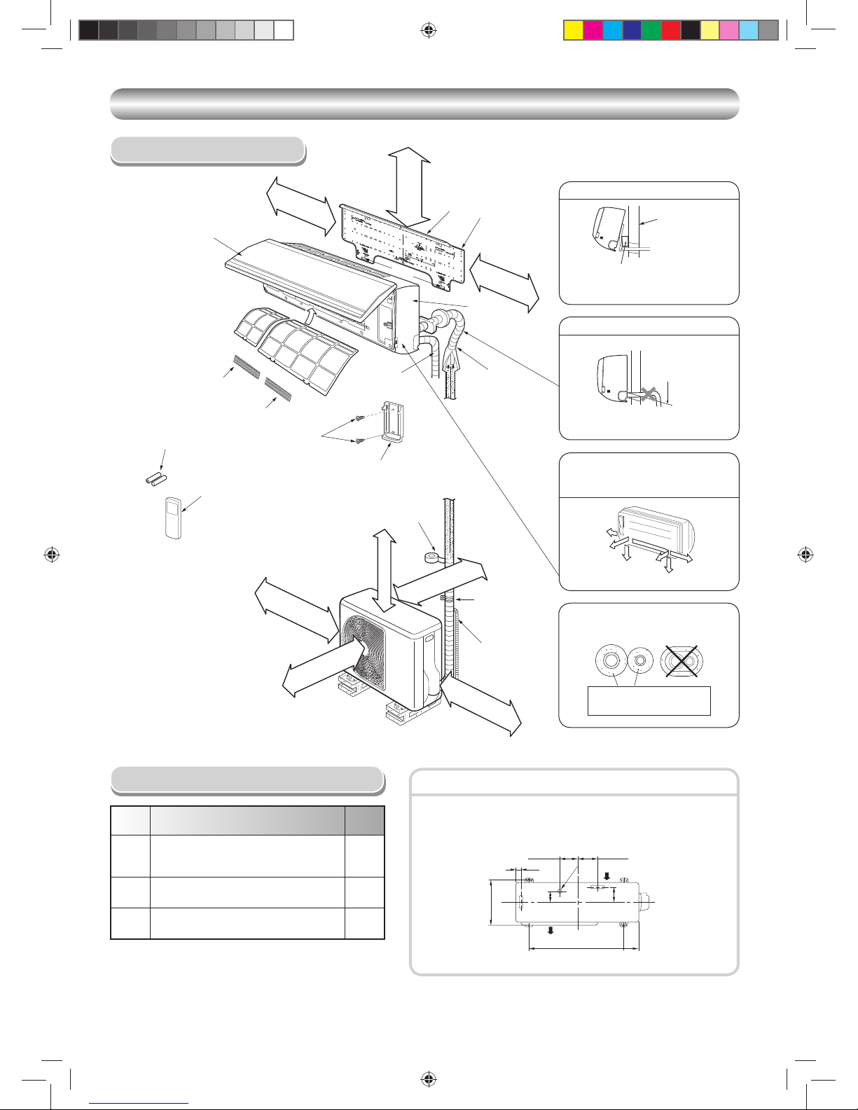
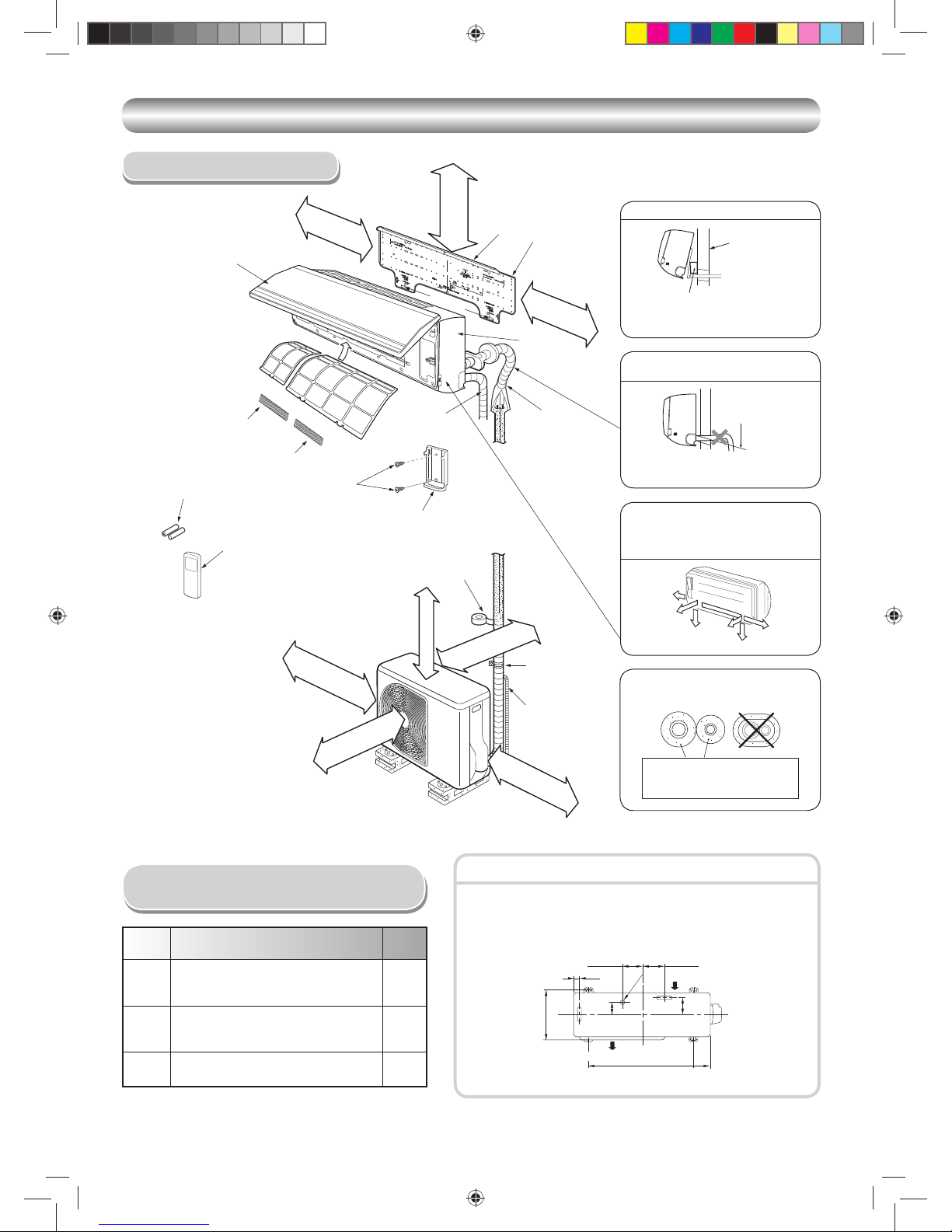
INSTALLATION DIAGRAM OF INDOOR AND OUTDOOR UNITS
INSTALLATION DIAGRAM OF INDOOR AND OUTDOOR UNITS
Part
code
Parts name Q’ty
A
Refrigerant piping
Liquid side : Ø1/4 in. (Ø6.35 mm)
Gas side : Ø3/8 in. (Ø9.52 mm)
One
each
B
Pipe insulating material
(polyethylene foam, 5/16 in. (8 mm) thick)
1
C
Putty, PVC tapes
One
each
Field Supplied Installation Parts
• Secure the outdoor unit with fi xing bolts and nuts if the unit is likely to be
exposed to strong winds.
• Use Ø5/16 in. (Ø8 mm) or Ø3/8 in. (Ø10 mm) anchor bolts and nuts.
Fixing bolt arrangement of outdoor unit
Insulate the refrigerant pipes separately,
not together.
2
3
8
4
Insert the cushion between the indoor
unit and wall, and tilt the indoor unit for
better operation.
For rear left and left piping
Wall
Make sure to run the drain hose sloped
downward.
Do not allow the drain hose to get slack.
Cut the piping
hole slightly
sloped downward.
The auxiliary piping can be connected to
the left, rear left, rear right, right, bottom
right or bottom left.
Right
Rear
right
Bottom
right
Rear
left
Bottom left
Left
5/16 in. (8 mm) thick heat
resisting polyethylene foam
1
Batteries
Flat head
wood screw
Remote control holder
Vinyl tape
Apply after carrying
out a drainage test.
Wireless remote control
Saddle
Extension drain hose
(Not available,
provided by installer)
Shield pipe
(Attach to the front panel.)
Air fi lter
Installation
plate
2-9/16 in. (65 mm)
or more
7 in. (170 mm)
or more
3-15/16 in. (100 mm)
or more
3-15/16 in. (100 mm)
or more
23-5/8 in. (600 mm)
or more
23-5/8 in. (600 mm)
or more
6
5
Filter
Filter
Hook
Hook
24 in. (600 mm) or more
only when unobstructed to
the front and both sides.
4-1/4 in.
(108 mm)
1-1/8 in.
(28 mm)
4-15/16 in.
(125 mm)
Ø1 in.
(25 mm)
Air inlet
Air outlet
3-3/8 in.
(86 mm)
4 in.
(102 mm)
12-19/32 in.
(320 mm)
23-5/8 in.
(600 mm)
3-17/32 in.
(90 mm)
7 in. (170 mm)
or more
Conduit
Front
panel
Air inlet grille
CLEARANCES
Remark :
• Details of accessory and installation parts can
be found in the accessory section.
1110251291-2 EN.indd 61110251291-2 EN.indd 6 12/13/13 5:00 PM12/13/13 5:00 PM

EN
SI
7
OUTDOOR UNIT
OUTDOOR UNIT
Installation Location
• A location which provides enough spaces around the outdoor unit as
shown in the diagram above.
• A location which can bear the weight of the outdoor unit and does not
allow an increase in noise level and vibration.
• A location where the operation noise and discharged air do not disturb
your neighbors.
• A location which does not expose the unit to strong winds.
• A location free of combustible gases leaks.
• A location which does not block a passage.
• A location where drain water does not cause any problems.
• Depending on snow level, use a fi eld fabricated ice or snow stand.
• When the outdoor unit is to be installed in an elevated position, be sure to
secure it as described in the section above.
CAUTION
1. Install the outdoor unit in a location where there are no obstructions
near its air intake or air outlet.
2. When the outdoor units is installed in a place that is always exposed
to strong winds like on the coast or on a high story of a building, use
a fi eld fabricated wind baffl e. To minimize the effect of strong winds,
specially in windy areas, install the unit as shown below.
Strong
wind
90
Refrigerant Piping Connection
1. Make sure you have enough pipe to reach to the indoor unit.
2. Cut the pipe with a pipe cutter.
Flaring
Obliquity Roughness Warp
3. Insert a fl are nut into the pipe and fl are the pipe.
Wiring Connection
1. MOUNT THE OUTDOOR UNIT POWER DISCONNECT.
2. RUN POWER WIRING FROM MAIN BOX TO DISCONNECT PER NEC
AND LOCAL CODES.
3. Remove the valve cover and the cord clamp from the outdoor unit.
4. Fix conduit connector to conduit plate by lock nut and secure it tightly.
Connect the power supply and connecting cables to the terminal block as
shown in the fi gure in the next page and secure it tightly with screws.
5. You should not have extra cables.
6. Secure the power cord and the connecting cable with the cord clamp.
7. Attach the electric parts cover and the valve cover to the outdoor unit.
8. RUN PIPING AND INTERCONNECTING CABLE TO THE INDOOR
UNIT.
All wiring and connections must comply with NEC, CEC, and local codes.
• Connect all wires to the correct terminal on the wiring terminal blocks.
• Make sure that all connectors are secure.
• Size connectors per the ratings listed in the system requirement section.
• System interconnections should be minimum AWG14.
NOTE
CAUTION
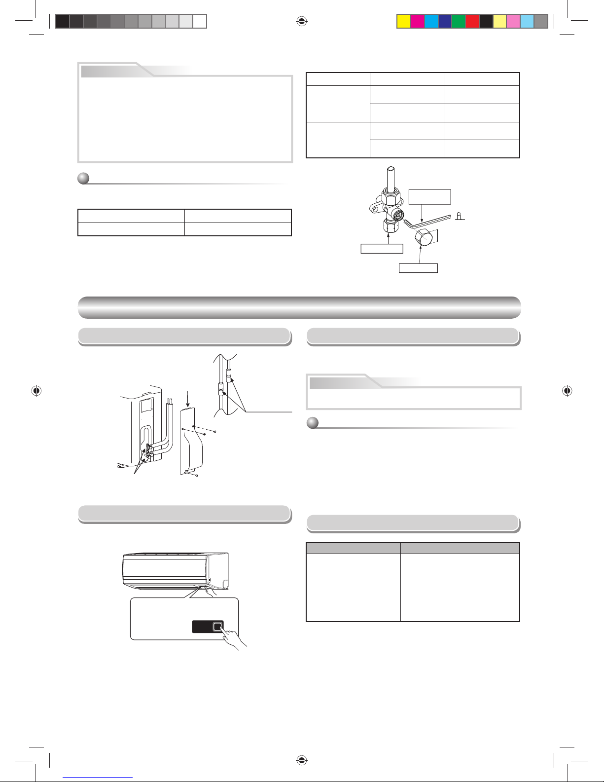
Align the centers of the connecting pipes and tighten the fl are nut as far as
possible with your fi ngers. Then tighten the nut with a two wrenches as show
below.
Tightening connection
Do not apply excess torque. Otherwise, the nut may crack depending on
the conditions.
Outer dia. of copper pipe Tightening torque
Ø1/4 in. (Ø6.35 mm) 10 to 13 lbf.ft (14 to 18 N·m)
Ø3/8 in. (Ø9.52 mm) 24 to 31 lbf.ft (33 to 42 N·m)
• Tightening torque for connection of fl are pipe
The pressure of R410A is higher than
R22. (Approx. 1.6 times.) Therefore
securely tighten the fl are pipes
which connect the outdoor unit and
the indoor unit with the specifi ed
tightening torque using a torque
wrench.
Half union Flare nut
Externally
threaded side
Internally
threaded side
Flare at
indoor unit side
Flare at
outdoor unit side
Use a wrench to secure. Use a torque wrench to tighten.
• Do not use the supplied drain nipple for draining water. Drain the water
from all drain holes directly.
• To protect the outdoor unit from snow accumulation, install a holding
frame, and attach a snow protection hood and plate.
* Do not use a double-stacked design.
Precautions about Installation in Regions
with Snowfall and Cold Temperatures
Snow protection plate
Snow protection hood
Snow accumulation line
Holding frame
At least
19-11/16 in. (500 mm)
Install the unit at least
19-11/16 in. (500 mm)
above the snow
accumulation line.
Anchor
bolts
Front
L2
L1
L2
L1
SS S
L1 L1 L1
L2 L2 L2
GND GND GND
FIELD POWER SUPPLY
208/230/1/60
DISCONNECT PER
NEC AND LOCAL CODE
INDOOR UNITOUTDOOR UNIT
LEGEND
DISCONNECT
PER NEC AND
LOCAL CODE
Field high voltage and ground wiring
Factory wiring
Field signal wiring
FIELD CONNECTION WIRING
1110251291-2 EN.indd 71110251291-2 EN.indd 7 12/13/13 5:00 PM12/13/13 5:00 PM
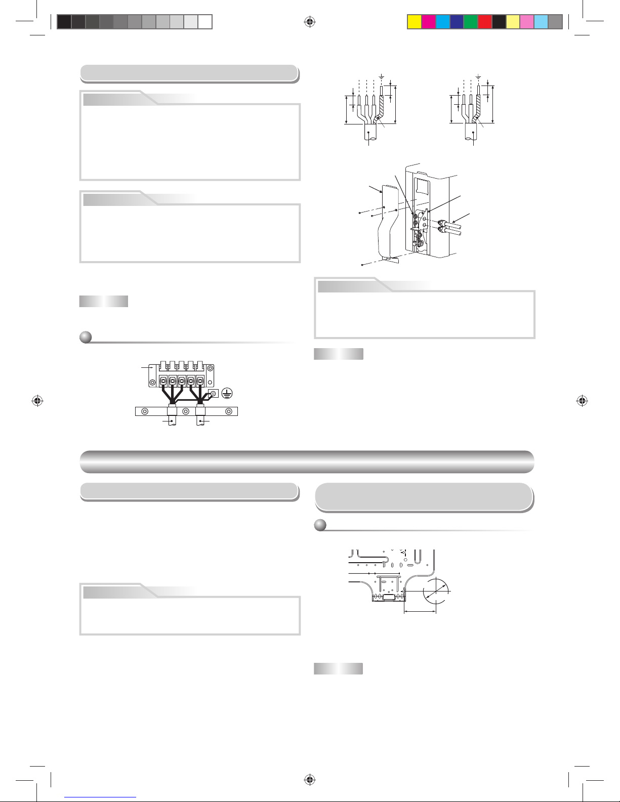
8
Stripping length of the Power supply cord and
Interconnecting cable
L1
L2
L1
L2
S
Interconnecting cable
Power supply cord
Terminal block
Unit : inch (mm)
L1
L2
L1
L2
S
Ground line
Connecting cable Power cord
Ground line
3/8 (10)
3/8 (10)
1-3/16 (30)
2-12/16 (70)
3/8 (10)
3/8 (10)
1-3/16 (30)
1-9/16 (40)
Conduit plate
Connector
Lock nut
Valve cover
NOTE : Interconnecting cable
• Wire type : minimum AWG14
CAUTION
• Wrong wiring connection may cause some electrical parts to fail.
• Be sure to comply with LOCAL CODES.
• Every wire must be connected fi rmly.
• If incorrect or incomplete wiring is carried out, it could cause an
ignition or smoke.
INDOOR UNIT
INDOOR UNIT
Installation Location
• Direct sunlight to the indoor unit’s wireless receiver should be avoided.
• The microprocessor in the indoor unit should not be too close to RF
noise sources.
(For details, see the owner’s manual.)
NOTE
• When drilling a wall that contains a metal lath, wire lath or metal plate, be
sure to use a hole saw.
After determining the pipe hole position on the mounting plate (➡), drill the
pipe hole Ø2-9/16 in. (Ø65 mm) at a slight downward slant to the outdoor
side.
• A location which provides the clearances around the indoor unit as shown
in the diagram in the “CLEARANCES” section.
• A location where there are no obstacles near the air inlet and outlet
• A location which allows easy installation of the piping to the outdoor unit
• A location which allows the front panel to be opened
• The indoor unit shall be installed such that the top of the indoor unit
comes to at least 6.6 ft (2 m) height. Also avoid putting anything on the top
of the indoor unit.
• A location that will bear the weight of the unit.
CAUTION
Cutting a hole
When installing the refrigerant pipes from the rear
80 100 180
The center of the pipe
hole is above the arrow.
Pipe hole
Ø2-9/16 in. (65 mm)
3-15/16 in.
(100 mm)
Cutting a Hole and Mounting the
mounting Plate
1. The supply voltage must be the same as the rated voltage of the air
conditioner.
2. Prepare the power source for exclusive use with the air conditioner.
NOTE : Power supply cord
• Wire type : minimum AWG14
CAUTION
UNIT DAMAGE HAZARD
Failure to follow this caution may result in equipment damage or improper
operation.
Unit failure as a result or of improper line voltage application or excessive
phase imbalance constitutes abuse and may cause damage to electrical
components. Such operation could void any applicable warranty.
Electrical Work
WARNING
ELECTRICAL SHOCK HAZARD
Failure to follow this warning could result in personal injury or death.
The unit cabinet must have an uninterrupted or unbroken ground
to minimize personal injury if an electrical fault should occur. The
ground may consist of electrical wire or metal conduit when installed in
accordance with existing electrical codes.
Make sure main power switch is turned OFF before performing service or
maintenance.
1110251291-2 EN.indd 81110251291-2 EN.indd 8 12/13/13 5:00 PM12/13/13 5:00 PM
EN
SI
9
3
1
2
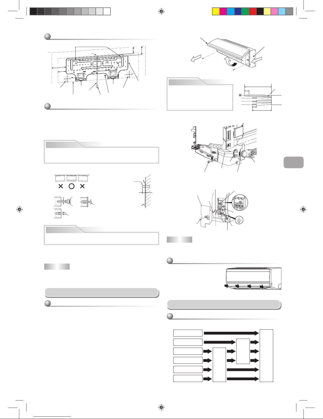
Mounting the mounting plate
When the mounting plate is directly mounted to
the wall
1. To hook up the indoor unit, securely fi t the mounting plate onto the wall by
screwing it in the upper and lower parts.
2. To mount the mounting plate on a concrete wall with, anchor bolts, drill the
anchor bolt holes as illustrated in the fi gure shown below.
3. Make sure the mounting plate is level.
1
7
Anchor bolt holes
Hook
Hook
Hook
Pipe hole Pipe hole
Mounting
plate
Mounting screw
Weight
Indoor unit
Thread
6.6 ft (2 m) or more
from fl oor
7 in.
(170 mm)
3-11/32 in.
(85 mm)
2-29/64 in.
(62 mm)
3-17/64 in.
(82.5 mm)
Wiring Connection
1. Open the air inlet grille upward.
2. Remove the screws securing the front panel.
3. Slightly open the lower part of the front panel, then pull the upper part of
the front panel toward you to remove it from the rear plate.
4. Insert the conduit pipe (according to local codes) into the pipe hole on
the wall.
5. Remove the conduit mount by loosening the fi xing screw (Fig. 1)
6. Fix conduit pipe to conduit mount with the lock nut.
7. Pull out the connecting wire through the conduit pipe and process the
wire. (Fig. 3)
8. Take out the wire to the front and fi x it to the terminal block.
Be careful not to mis-wire. (Fig. 2)
9. Firmly tighten the terminal screws to prevent them from loosening.
Tightening torque: 0.9 lbf.ft (1.2 N·m). After tightening, pull the wires
lightly to confi rm that they do not move.
10. Secure the connecting wire with the cord clamp.
11. Fix the conduit mount back to the body by fi xing a screw.
12. Fix the front panel, terminal cover and air inlet grille to the indoor unit.
How to connect the connecting cable
NOTE
• Use stranded wire only.
• Wire type : minimum AWG14
CAUTION
S
L
2
L1
Ground
line
4-5/16 in. (110 mm)
3-5/32 in. (80 mm)
13/16 in. (20 mm)
3/8 in. (10 mm)
• Be sure to refer to the system wiring
diagram located inside the front panel.
• Check local electrical codes and also
any specifi c wiring instructions or
limitations.
Fig. 3
Fig. 2 Wiring
L
1
L
2
S
L
1
L
2
S
Cord clamp
Terminal block
Terminal cover
Screw
Ground line
Screw
Connecting cable
Screw
Front panel
CAUTION
Failure to fi rmly install the unit may result in personal injury and property
damage if the unit falls.
• In case the unit is to be installed in a block, brick, concrete or similar type
walls, make 3/16 in. (5 mm) dia. holes in the wall.
• Insert clip anchors for appropriate mounting screws 7.
NOTE
• Secure four corners and lower parts of the mounting plate with 4 to 6
mounting screws to install it.
7
CAUTION
Installation plate
(Keep horizontal direction.)
3/16 in. (5 mm) dia. hole
Mounting screw
Ø5/32 in. × 1 in.
(Ø4 mm × 25 mm)
Clip anchor
(fi eld supplied parts)
Anchor bolt
Projection
9/16 in. (15 mm)
or less
When installing the mounting plate with a mounting screw, do not use the
anchor bolt holes. Otherwise, the unit may fall down and result in personal
injury and property damage.
Air inlet grille
Front panel
Conduit pipe
Conduit mount
Fixing screw
Lock nut
Interconnecting
cable
Fig. 1 Construction
Piping and Drain Hose Installation
INSULATE BOTH LINES.
Piping and drain hose forming
Rear right
Rear left
Bottom left
Left
Bottom right
Right
Die-cutting
front panel slit
Changing
drain hose
Piping preparation
How to install the air inlet grille on the indoor
unit
• When attaching the air inlet grille,
perform the same process as for
removal but in reverse order.
1110251291-2 EN.indd 91110251291-2 EN.indd 9 12/13/13 5:00 PM12/13/13 5:00 PM
10
Firmly insert the drain hose and drain cap; otherwise, water may leak.
In case of right or left piping
• After making slits of the front panel with a
knife or a making-off pin, cut them with a
pair of nippers or an equivalent tool.
In case of bottom right or bottom left piping
• After making slits of the front panel with a
knife or a making-off pin, cut them with a
pair of nippers or an equivalent tool.
Left-hand connection with piping
• Bend the connecting pipe so that it is laid within 1-5/8 in. (43 mm) above
the wall surface. If the connecting pipe is laid exceeding 1-5/8 in. (43 mm)
above the wall surface, the indoor unit may be unstable on the wall.
When bending the connecting pipe, make sure to use a spring bender to
avoid crushing the pipe.
Bend the connecting pipe within a radius of 1-3/16 in. (30 mm).
To connect the pipe after the unit has been installed (fi gure)
CAUTION
Slit
Slit
80
Liquid side
Gas side
(To the forefront of fl are)
Outward form of indoor unit
R 1-3/16 in. (R 30 mm) (Use polisin
(polyethylene) core or the like for
bending pipe.)
Use the handle of a screwdriver, etc.
6-11/16 in.
(170 mm)
1-5/8 in.
(43 mm)
10-5/8 in.
(270 mm)
How to remove the drain cap
Clip the drain cap with needle-nose
pliers and pull out.
How to fi x the drain cap
1) Insert a hexagon wrench
3/16 in. (4 mm) in the
center head of the cap.
2) Firmly insert the drain cap.
3/16 in.
(4 mm)
No gap
Do not apply lubricating oil
(refrigerant machine oil) when
inserting the drain cap. Application
causes deterioration and drain
leakage from the plug.
Insert a hexagon
wrench 3/16 in.
(4 mm).
How to remove the drain hose
• The drain hose can be removed by removing the
screw securing the drain hose and then pulling out
the drain hose.
• When removing the drain hose, be careful of any
sharp edges the steel plate may have. Sharp
edges can cause injuries.
• To install the drain hose, insert the drain hose
fi rmly until the connection part contacts the heat
insulator, and then secure it with the original
screws.
Heat insulator
Drain hose
NOTE
If the pipe is bent incorrectly, the indoor unit may be unstable on the wall.
After passing the connecting pipe through the pipe hole, connect the
connecting pipes to the refrigerant line and wrap facing tape around them.
CAUTION
• Bind the refrigerant lines (two) and connecting cable with facing tape
tightly. In case of leftward piping and rear-leftward piping, bind the
refrigerant lines (two) only with facing tape.
Indoor unit
Connecting cable
Refrigerant lines
Installation plate
• Carefully arrange pipes such that none of them stick out of the rear
plate of the indoor unit.
• Carefully connect the refrigerant lines and connecting pipes to one
another and cut off the insulating tape wound on the connecting pipe
to avoid double-taping at the joint; moreover, seal the joint with vinyl
tape, etc.
• Check for gas leaks before insulating.
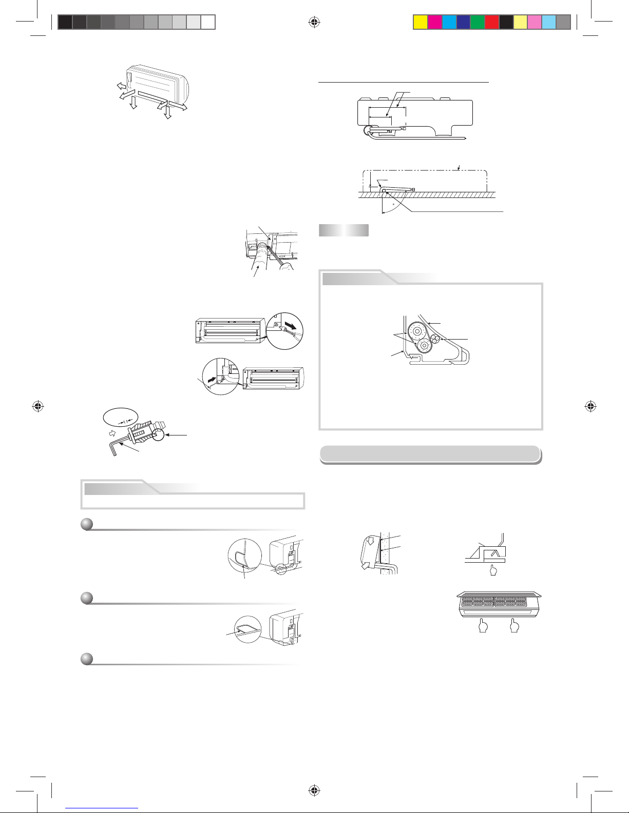
Indoor Unit Fixing
• To detach the indoor unit from the
mounting plate, pull the indoor unit toward
you while pushing its bottom up as shown
in the fi gure.
1
2
1
1. Pass the pipe through the hole in the wall and hook the indoor unit on the
upper hook of the installation plate.
2. Swing the indoor unit to the right and left to confi rm that it is fi rmly hooked
up to the mounting plate.
3. While pressing the indoor unit onto the wall, hook it to the lower section
of the mounting plate. Pull the indoor unit toward you to confi rm that it is
fi rmly hooked up to the mounting plate.
Hook here.
Installation plate
Hook
Press
(unhook)
Push Push
1. Die-cutting front panel slit
With a pair of nippers, cut out the slit on the leftward or right side of the
front panel for the left or right connection, and the slit on the bottom left or
right side of the front panel for the bottom left or right connection.
2. Changing drain hose
For leftward connection, bottom-leftward connection and rearleftward
connection’s piping, it is necessary to change the drain hose and drain
cap.
Right
Rear right
Bottom
right
Rear
left
Bottom left
Left
1110251291-2 EN.indd 101110251291-2 EN.indd 10 12/13/13 5:00 PM12/13/13 5:00 PM
EN
SI
11
Drainage
1. Run the drain hose slopping downward.
NOTE
• The hole should be made at a slight downward slant on the outdoor side.
• The drain is internally trapped. An external trap is not required.
Do not rise the
drain hose.
Do not form the
drain hose into
a wavy shape.
2 in.
(50 mm)
or more
Do not put the
drain hose end
into water.
Do not put the
drain hose end
in the drainage ditch.
2. Put water in the drain pan and make sure that the water is drained out.
3. When connecting an extension drain hose, insulate it with shield pipe.
Shield pipe
Drain hose
Extension drain hose
Inside the room
Arrange the drain pipe for proper drainage from the unit.
Improper drainage can result in dew-dropping.
This air conditioner has the structure designed
to drain water collected from dew, which forms
on the back of the indoor unit, to the drain pan.
Therefore, do not store the power cord and other
parts at a height above the drain guide.
CAUTION
Wall
Drain
guide
Space for pipes
Remote control
• Place the remote control away from obstacles (such as curtain) that may
block the signal coming from the remote control.
• Do not install the remote control in a place exposed to direct sunlight or
close to a heating source such as a stove.
• Keep the remote control at least 3.3 ft (1 m) apart from the nearest TV set
or stereo equipment. (This is necessary to prevent image disturbances or
noise interference.)
• The location of the remote control should be determined as shown below.
54 °
4
5°
5
7
°
Indoor unit
(Side view)
(Top view)
Indoor unit
Remote
control
Remote
control
Reception
range
Reception range
Remote Control A-B Selection
In case of two systems operating nearby, follow the instructions below to set
the remote control to operate with one indoor unit at a time.
Remote Control B Setup.
1. Press RESET button on the indoor unit to turn the air conditioner ON.
2. Point the remote control at the indoor unit.
3. Push and hold CHK ● button on the Remote Control with the tip of a
pencil. “00” will be shown on the display.
4. Press
MODE
while pushing CHK ●. “B” will show on the display and
“00” will disappear and the air conditioner will turn OFF. B is now
memorized.
Note: 1. Repeat above step to reset Remote Control back to A.
2. Remote Control does not display “A”.
3. Default setting of Remote Control from factory is A.
“B” Display
“00” Display
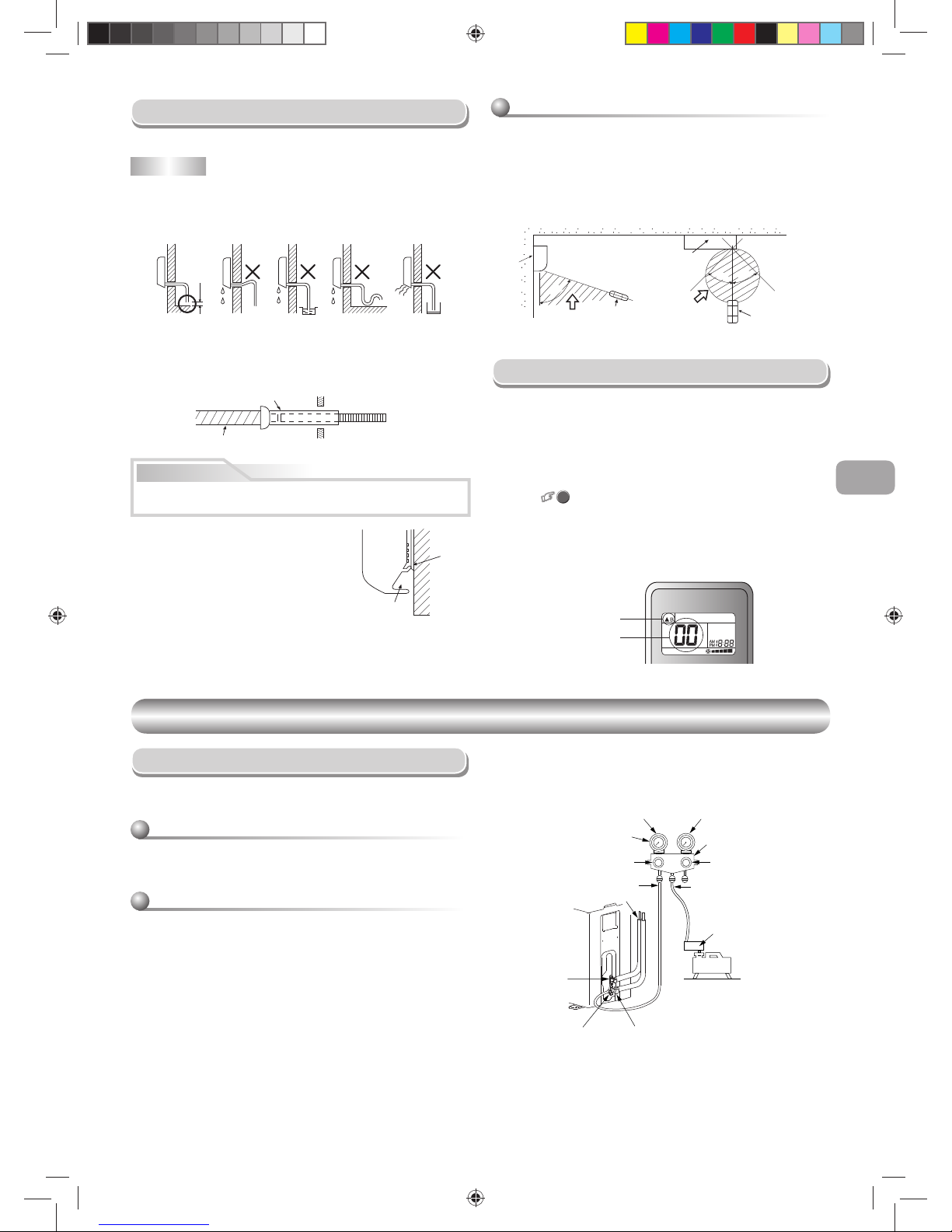
Evacuating
After the piping has been connected to the indoor unit, you can vacuum both
units at once.
Be sure to use a vacuum pump with counter-fl ow prevention function so
that inside oil of the pump does not fl ow backward into pipes of the air
conditioner when the pump stops.
(If oil inside of the vacuum pump enters the air conditioner, which uses
R410A, refrigeration cycle trouble may happen.)
1. Connect the charge hose from the manifold valve to the service port of
the packed valve at the gas side.
2. Connect the charge hose to the port of the vacuum pump.
3. Open fully the low pressure side handle of the manifold valve gauge.
4. Operate the vacuum pump to start evacuating. Confi rm that the
compound pressure gauge reading is –101 kPa (–76 cmHg) and
500 microns or lower.
5. Close the low pressure side valve handle of the manifold valve gauge.
Using a vacuum pump
Evacuate the air in the connecting pipes and in the indoor unit using a
vacuum pump. Do not re-use the refrigerant in the outdoor unit. For details,
see the vacuum pump manual.
VACUUMING
EVACUATING
EVACUATING
Packed valve at
liquid side
Service port (Valve core
(Setting pin))
Packed valve at gas side
Vacuum
pump
Vacuum pump adapter for
counter-fl ow prevention
(For R410A only)
Charge hose
(For R410A only)
Handle Hi
(Keep full closed)
Manifold valve
Pressure gauge
Compound pressure gauge
Handle Lo
Charge hose
(For R410A only)
Connecting pipe
–101 kPa
(–76 cmHg)
6. Open fully the valve stem of the packed valves (both gas and liquid
sides).
7. Remove the charging hose from the service port.
8. Securely tighten the packed valves cap.
1110251291-2 EN.indd 111110251291-2 EN.indd 11 12/13/13 5:00 PM12/13/13 5:00 PM
12
Packed valve handling precautions
• Open the valve stem all the way out, but do not try to open it beyond the
stopper.
• Securely tighten the valve cap with torque in the following table:
Pipe size of Packed Valve Size of Hexagon wrench
1/2 in. (12.7 mm and smallers) A = 3/16 in. (4 mm)
Cap Cap Size (H) Torque
Valve Rod Cap
43/64 in. - 3/4 in.
(H17 - H19)
10 to 13 Ibf.ft
(14~18 N·m)
55/64 in. - 1-3/16 in.
(H22 - H30)
24 to 31 Ibf.ft
(33~42 N·m)
Service Port Cap
35/64 in.
(H14)
37 to 46 Ibf.ft
(50~62 N·m)
43/64 in.
(H17)
10 to 13 Ibf.ft
(14~18 N·m)
A
H
Hexagon wrench
is required.
Service Port Cap
Valve Rod Cap
OTHER
OTHER
Gas Leak Test
Test Operation
Troubleshooting (Check Point)
To switch the TEST RUN (COOL) mode, press RESET button for 10 seconds.
(The beeper will make a short beep.)
Auto Restart Setting
The product was shipped with Auto Restart function in the ON position.
Turn it OFF if this function is not required.
How to cancel the Auto Restart
Check fl are nut
connections for gas
leak with a gas leak
detector or soap
water.
This product is designed so that after a power failure it can restart
automatically in the same operating mode as before the power failure.
1. Press and hold the RESET button on the indoor unit for 3 seconds to
cancel the ope
ration. (3
beeps will
sound but OPERATION lamp does not
blink)
2. Press and hold the RESET button on the indoor unit for 3 seconds to set
the operation. (3 beeps will sound and OPERATION lamp blink 5 time/
sec for 5 seconds)
• Do not operate ON timer and OFF timer.
Note : Default setting of auto restart operation is ON.
Check places with
fl are nut connections
(indoor unit)
Check places for
outdoor unit.
Valve cover
Information
RESET
RESET button
The unit does not operate. Cooling or Heating is abnormally low.
• The power main switch is
turned off.
• The circuit breaker is tripped.
• ON timer is set.
• The fi lters are blocked with dust.
• The temperature has been set
improperly.
• Windows or doors are open.
• The air inlet or outlet of the outdoor
unit is blocked.
• The fan speed is too low.
• The operation mode is FAN or DRY.
CAUTION
• 5 IMPORTANT POINTS FOR PIPING WORK.
(1) Take away dust and moisture (inside of the connecting pipes).
(2) Tighten the connections (between pipes and unit).
(3) Evacuate the air in the connecting pipes using a VACUUM PUMP.
(4) Check gas leak (connected points).
(5) Be sure to fully open the packed valves before operation.
• UNIT DAMAGE HAZARD
Failure to follow this caution may result in equipment damage or
improper operation.
Never use the system compressor as a vacuum pump.
1110251291-2 EN.indd 121110251291-2 EN.indd 12 12/13/13 5:00 PM12/13/13 5:00 PM
2-23/32 (69)
)572( 8/7-01
3-17/32 (90)
3-17/32 (90)
23-5/8 (
600
)
17-5/32 (
436
)
)023( 23/91-21
4-1/4 (
108
)
4-15/16 (
125
)
( 8/3-3
68
)
( 61/9-4
611
)
A
B
13-1/2 (342)
( 61/11-12
055
)
11-7/16 (
290
)
( 2
3/3-2
35
)
(
23/5
1
3
88
)
( 6
1/9-5
141
)
1-27/64 (36)
1-31/32 (50)
(R15)
R19/32
)023( 23/91-21
23-5/8 (600)
)603( 46/3-21
1-27/64 (36)
1-31/32 (50)
R19/32 (R15)
23-5/8 (600)
)023( 23/91-21
)603( 4
6/3-21
23-5/8 (
600
)
)
0
23(
23/9
1
-21
2
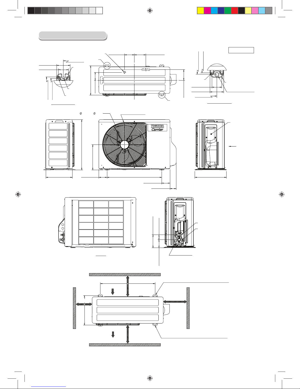
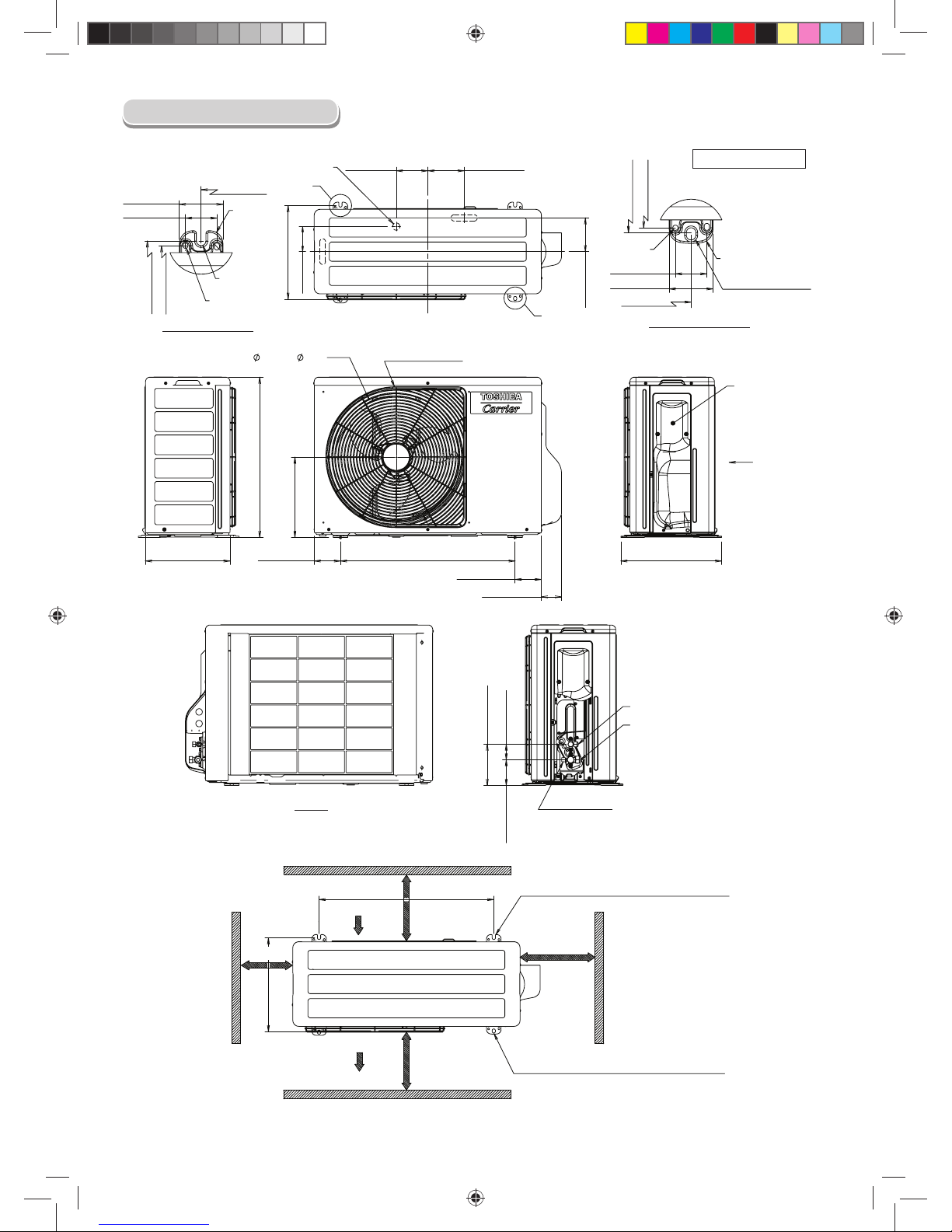
Ø1 (Ø25) Water Drain Outlet
Detail-A (Rear Leg)
R7/32
(R5.5)
Ø1/4 Hole
(Ø6) Hole
Ø1/4 Hole
(Ø6) Hole
Ø7/16x9/16 Oval-Hole
(Ø11x14) Oval-Hole
Detail-B (Front Leg)
COVER
PACKED VALVE
View Z
WIRE GUARD
View Z
Liquid side
(Flare Nut : Ø1/4 (Ø6.35))
Gas side
(Flare Nut : Ø3/8 (Ø9.52))
Service Port
Air Inlet
Air Outlet
3-15/16 or more
(100 mm or more)
23-5/8 or more
(600 mm or more)
2-R7/32x43/64L (R5.5x17L) U-Shape
(For Ø5/16~ Ø13/32 (Ø8~ Ø10) Anchor Bolt)
2-Ø7/16x9/16 (Ø11x14) Oval-Hole
(For Ø5/16~Ø13/32 (Ø8~Ø10) Anchor Bolt)
3-15/16 Inch or more
(100 mm or more)
23-5/8 Inch or more
(600 mm or more)
Unit : Inch (mm)
Outdoor Unit
1110251291-2 EN.indd 21110251291-2 EN.indd 2 12/13/13 5:00 PM12/13/13 5:00 PM
1
ES
DIMENSIONES
DIMENSIONES
Unidad interior
2-15/32(63)
7-15/32(190)
6-5/16(161) 5-1/2(150)
10-13/16(275)
1-9/16(40)
1-9/16(40)
1-3/4(45)
7-19/32(193)18-7/8(480)
2-7/16(62) 2-11/16(69)
1-7/8(48)
2-15/32(63)
9/32(7)
1-7/8(48)
4-9/16(116)
10-25/32(275)
1-7/8(48)
9/32(7)
24-7/16(621)
8-1/16(205)
31-1/8(790)
8-7/16(215)
9-1/4(235)
9-1/4(235)
8-7/16(215)
6-5/16(161)5-1/2(150)
Panel frontal
Hueco para tuberías por
la izquierda
Filtro de aire
Entrada
de aire
Radiador
Hueco para tuberías por la
derecha
Hueco para tuberías por abajo a
la izquierda
Hueco para tuberías por
abajo a la derecha
Pestaña para la placa de pared
Agujero para
tubería (agujero
de Ø7/8(22))
Tubería de conexión
(18-5/8(0,40m))
(Abocardado de Ø1/4(6,35))
Pestaña para la
placa de pared
Tubería de conexión
(13-25/32(0,35m))
(Abocardado de Ø3/8(9,52))
Manguera de drenaje
(19-11/16(0,50m))
3-5/16(84,5)
3-5/16(84,5)
3-5/16(84,5)3-5/16(84,5)
Colgador
Colgador
Colgador
Línea central
Forma de la plancha de
montaje
Distancia
mínima a la
pared
Distancia
mínima a
la pared
Distancia
mínima a la
pared
6-11/16(170)o más
6-11/16(170)o más
2-9/16(65)o más
Rejilla de entrada
Salida de
aire
Para espárrago (Ø2-1/4(6))
Para espárrago (Ø5/16(8)~Ø13/32(10))
Unidad : Pulgada (mm)
Mando a distancia
Soporte del mando a distancia
31/32 (26)
3/4 (19)
2-15/32 (63)
2-3/16 (56)
4-29/32 (125)
6-3/4 (157)
1110251291-2 ES.indd 11110251291-2 ES.indd 1 12/17/13 4:58 PM12/17/13 4:58 PM
2
2-23/32 (69)
)572( 8/7-01
3-17/32 (90)
3-17/32 (90)
23-5/8 (
600
)
17-5/32 (
436
)
)023( 23/91-21
4-1/4 (
108
)
4-15/16 (
125
)
( 8/3-3
68
)
( 61/9-4
611
)
A
B
13-1/2 (342)
( 61/11-12
055
)
11-7/16 (
290
)
( 2
3/3-2
35
)
(
23/5
1
3
88
)
( 6
1/9-5
141
)
1-27/64 (36)
1-31/32 (50)
(R15)
R19/32
)023( 23/91-21
23-5/8 (600)
)603( 46/3-21
1-27/64 (36)
1-31/32 (50)
R19/32 (R15)
23-5/8 (600)
)023( 23/91-21
)603( 4
6/3-21
23-5/8 (
600
)
)
0
23(
23/9
1
-21
Agujero de drenaje de agua de Ø1 (Ø25)
Detalle A (Pata trasera)
R7/32
(R5,5)
Agujero de Ø1/4
Agujero de (Ø6)
Agujero de Ø1/4
Agujero de (Ø6)
Agujero oval de Ø7/16x9/16
Agujero oval de (Ø11x14)
Detalle B (Pata delantera)
CUBIERTA DE LA
VÁLVULA DE
RELLENO
Vista Z
PROTECTOR DEL
CABLE
Vista Z
Lado líquido
(Tuerca de abocardado de : Ø1/4 (Ø6,35))
Lado de gas
(Tuerca de abocardado de : Ø3/8 (Ø9,52))
Orificio de salida
Entrada de aire
Salida de aire
3-15/16 o más
(100 mm o más)
23-5/8 o más
(600 mm o más)
2-R7/32x43/64L (R5,5x17L) en forma de U
(Para tuercas de anclaje de Ø5/16~ Ø13/32 (Ø8~Ø10))
Agujero oval de 2-Ø7/16x9/16 (Ø11x14)
(Para tuercas de anclaje de Ø5/16~Ø13/32 (Ø8~Ø10))
3-15/16 Pulgada
o más
(100 mm o más)
23-5/8
Pulgada o más
(600 mm
o más
)
Unidad : Pulgada (mm)
Unidad exterior
1110251291-2 ES.indd 21110251291-2 ES.indd 2 12/17/13 4:58 PM12/17/13 4:58 PM
3
ES
• La distancia mínima de la línea de refrigerante entre las unidades interior
y exterior es de 2m (6,6 pies).
• Distancia máxima de las tuberías
REQUISITOS DE INSTALACIÓN
REQUISITOS DE INSTALACIÓN
Longitud máxima permitida
para las tuberías T
(pies (metros))
Diferencia de altura
(Interior - Exterior H)
(pies (metros))
66 (20) 33 (10)
Tamaños de las tuberías de refrigerante
HT
Lado líquido Lado de gas
Diámetro exterior
Pulgadas (mm)
Grosor
Pulgadas (mm)
Diámetro exterior
Pulgadas (mm)
Grosor
Pulgadas (mm)
Ø1/4 (6,35) 0,03 (0,8) Ø3/8 (9,52) 0,03 (0,8)
Aislamiento
Ambas líneas deben estar aisladas. Utilice un muro de grosor mínimo de
5/16 pulgadas (8mm).
Carga del refrigerante
Unidad : pies (m)
Carga del refrigerante
Longitud de la tubería de
refrigerante conectada
a las unidades exterior e
interior
Refrigerante adicional
6,6-50
(2-15m)
Nada
50-66
(15-20m)
Añada 20g/m (0,22oz/pie) de refrigerante
para tuberías que sean mayores de 15m
(50 pies) y hasta 20m (66 pies).
* Tenga cuidado durante la carga de refrigerante adicional
La cantidad máxima de refrigerante adicional es 100g (0,22lbs).
Cargue el sistema con precisión. Una sobrecarga puede dañar el
compresor.
* La longitud mínima de la tubería del refrigerante es de 2m (6,6 pies).
Si usa una tubería más corta puede provocar un mal funcionamiento del
compresor u otros componentes.
Cableado de alimentación
La fuente de alimentación se suministra a la unidad exterior. El cable de
conexión de campo suministrado desde la unidad exterior a la unidad
interior consiste en (3) cables y proporciona la energía para la unidad
interior. Dos cables tienen energía de alto voltaje AC y uno de ellos es un
cable de tierra.
Consulte los códigos de construcción locales y el NEC (Código Nacional
de Electricidad) o CEC (Código Canadiense de Electricidad) para obtener
requisitos especiales.
Todos los cables se deben medir por NEC o CEC y códigos locales. Utilice
la tabla de Datos eléctricos MCA (Amperios mínimos del circuito) y MOCP
(Sobre protección máxima del dispositivo) para medir correctamente los
cables y el fusible de desconexión o frenos respectivamente.
Solo se pueden utilizar conductores de cobre con un índice de 300 voltios
mínimo y un aislamiento de 2/64 pulgadas de grosor.
La interconexión de cable entre FCU y CDU debe ser de un mínimo AWG14.
Tuberías (Suministradas en el campo)
1110251291-2 ES.indd 31110251291-2 ES.indd 3 12/17/13 4:58 PM12/17/13 4:58 PM
4
PRECAUCIONES DE SEGURIDAD
PRECAUCIONES DE SEGURIDAD
• Antes de la instalación, por favor lea con atención estas precauciones de seguridad.
• Asegúrese de seguir las precauciones proporcionadas aquí para evitar riesgos de seguridad. Abajo aparecen los símbolos y sus signifi cados.
PRECAUCIÓN
• ESTE SISTEMA DE AIRE ACONDICIONADO UTILIZA EL REFRIGERANTE HFC (R410A), QUE NO DAÑA LA CAPA DE OZONO.
El refrigerante R410A puede verse afectado por impurezas como agua y aceite dado que la presión del mismo es aproximadamente 1,6 veces la del
refrigerante R22.
ADEMÁS, CON EL R410A SE USAN NUEVOS ACEITES, POR LO QUE DEBE USAR UNA NUEVA TUBERÍA DE REFRIGERANTE Y NO PERMITIR
QUE ENTRE HUMEDAD O POLVO EN EL SISTEMA.
Para evitar el riesgo de mezclar refrigerante y aceite de la máquina, los tamaños de las válvulas de carga en la unidad principal son diferentes de
aquellos que usados en máquinas R22, y deberá usar herramientas diferentes.
• RIESGO DE DAÑOS AL EQUIPO
En caso de no seguir esta advertencia puede provocar daños al equipo o un funcionamiento inadecuado.
No entierre más de 914mm (36 pulgadas) de tubería de refrigerante en el suelo. Si una sección de la tubería queda enterrada, debe haber una elevación
vertical de 152 mm (6 pulgadas) hacia las válvulas de conexión de la unidad exterior. Si entierra más de la longitud recomendada, el refrigerante podría
desplazarse hacia la sección enterrada durante largos periodos de tiempo sin usar el equipo. Esto puede provocar pegotes de refrigerante y daños al
compresor durante el encendido.
Instalación de sistema de aire acondicionado con un nuevo refrigerante
PELIGRO
• SOLAMENTE PARA EL USO DE PERSONAS CUALIFICADAS.
• DESACTIVE LA FUENTE DE ALIMENTACIÓN PROVISTA Y EL CORTACIRCUITOS ANTES DE INTENTAR REALIZAR CUALQUIER TRABAJO
ELÉCTRICO. ASEGURESE DE QUE TODOS LOS INTERRUPTORES DE ALIMENTACIÓN Y CORTACIRCUITOS ESTÉN DESACTIVADOS, SI NO
LO HACE PODRÍA CAUSAR DESCARGAS ELÉCTRICAS.
• CONECTE EL CABLE DE CONEXIÓN CORRECTAMENTE. SI ESTE CABLE FUESE CONECTADO ERRONEAMENTE, SE PODRÍAN DAÑAR LAS
PARTES ELÉCTRICAS.
• COMPRUEBE QUE EL CABLE DE LA TOMA DE TIERRA NO ESTÉ ROTO O DESCONECTADO ANTES DE LA INSTALACIÓN.
• NO INSTALE LA UNIDAD CERCA DE CONCENTRACIONES DE GAS INFLAMABLE O VAPORES DE GAS.
SI FALLA EN CUMPLIR CON ESTA INSTRUCCION PODRIA RESULTAR EN UN INCENDIO O UNA EXPLOSIÓN.
• PARA EVITAR EL RECALENTAMIENTO DE LA UNIDAD INTERIOR Y LA CAUSA DE POSIBLES INCENCIOS, COLOQUE LA UNIDAD BIEN LEJOS
(A MÁS DE 2 METROS) DE FUENTES DE CALEFACCIÓN TALES COMO RADIADORES, CALEFACTORES, ESTUFAS, HORNOS, ETC.
• CUANDO TRASLADE EL ACONDICIONADOR DE AIRE TENGA MUCHO CUIDADO DE NO MEZCLAR EL REFRIGERANTE ESPECIFICADO
(R410A) CON NINGÚN OTRO CUERPO GASEOSO EN EL CICLO DE REFRIGERACIÓN. SI SE MEZCLA AIRE O CUALQUIER OTRO GAS
CON EL REFRIGERANTE, LA PRESIÓN DE GAS EN EL CICLO DE REFRIGERACIÓN SE VUELVE ANORMALMENTE ALTO PROVOCANDO LA
EXPLOSIÓN DE LA TUBERÍA Y DAÑOS A PERSONAS.
• EN EL CASO DE FUGA DE REFRIGERANTE DURANTE LA INSTALACIÓN, PERMITA QUE ENTRE AIRE FRESCO EN LA HABITACIÓN
INMEDIATAMENTE. SI EL GAS REFRIGERANTE SE CALIENTA CON FUEGO O CON CUALQUIER OTRO MEDIO, GENERA GAS VENENOSO.
La instalación, revisión y reparación de los equipos de aire acondicionado puede ser peligrosa debido a la presión del sistema, los componentes eléctricos
y la localización de los dispositivos (techos, estructuras elevadas, etc.).
Sólo los instaladores cualifi cados y entrenados y el personal de servicio deben instalar, revisar y reparar este equipo.
El personal no cualifi cado puede llevar a cabo tareas básicas de mantenimiento tales como la sustitución de fi ltros. Todas las demás tareas deben ser
llevadas a cabo por personal técnico cualifi cado.
Cuando esté trabajando con este equipo, siga las instrucciones de seguridad de los manuales y etiquetas, pegatinas y rótulos que existan en el mismo.
Siga todas las normativas de seguridad, use gafas de seguridad y guantes de trabajo. Tenga a mano paños y extintores de incendios cuando haga
soldaduras. Tenga cuidado al manipular, colocar y desplazar equipos pesados.
Lea estas instrucciones cuidadosamente y siga todas las advertencias y notas de seguridad incluidas en el manual y adjuntas al equipo. Consulte en las
normativas locales de instalaciones eléctricas y el código nacional de electricidad (NEC) los requisitos especiales. Este es el símbolo de alerta de seguridad
å
. Cuando vea este símbolo en la unidad y en los manuales de instrucciones, tenga en cuenta que existe un peligro potencial de lesiones personales.
Tenga en cuenta estas palabras de advertencia: PELIGRO, ATENCIÓN y ADVERTENCIA. Estas palabras se utilizan junto con el símbolo de alerta de
seguridad.
PELIGRO indica las amenazas más serias que pueden provocar daños personales severos e incluso la muerte. ATENCIÓN indica amenazas que pueden
causar daños personales. PRECAUCIÓN se usa para identifi car prácticas peligrosas que pueden dar lugar a daños personales menores o daños al
producto y al hogar. NOTA se usa para resaltar sugerencias encaminadas a una mejor instalación, funcionamiento o fi abilidad.
1110251291-2 ES.indd 41110251291-2 ES.indd 4 12/17/13 4:58 PM12/17/13 4:58 PM
5
ES
PRECAUCIÓN
• La exposición de la unidad al agua o a cualquier otro tipo de humedad antes de la instalación puede provocar un cortocircuito. No almacene la unidad
en un sótano mojado, ni la exponga a la lluvia ni al agua.
• Después de desembalajar la unidad, examínela cuidadosamente para ver si hay alguna avería. Comunique cualquier defecto a su distribuidor.
• No instale la unidad en un lugar que pueda aumentar la vibración de la misma. Tampoco la instale en un lugar que pueda amplifi car el nivel de ruido de
la unidad, o donde el ruido y el aire descargado puedan molestar a los vecinos.
• Por favor, lea este manual de instalación con atención antes de instalar la unidad. Contiene más instrucciones importantes para una correcta
instalación.
• Deberá conectar el aparato a la toma de alimentación mediante un cortocircuito dependiendo del sitio donde esté instalada la unidad. En caso contrario
podría producir una descarga eléctrica.
• Siga las instrucciones de este manual de instalación para reparar el tubo de drenaje para un correcto drenaje de la unidad. Asegúrese de que el agua
drenada se vacíe. Un drenaje incorrecto puede causar fugas de agua, produciendo daños de agua en su mobiliario.
• Tense la tuerca cónica con una llave dinamométrica utilizando el método prescrito. No aplique ningún exceso de torsión. En caso contrario, la tuerca
podría agrietarse pasado un largo período de uso y podría producir una fuga de refrigerante.
• Use guantes resistentes para la instalación. En caso contrario podría causarle lesiones personales manoseando las zonas con cantos puntiagudos.
• No toque la parte de entrada de aire o las aletas de aluminio de la unidad exterior. Podría causarle una herida.
• No instale la unidad exterior en un sitio donde los animales pequeños puedan tener sus nidos. Los animales pequeños podrían penetrar y entrar en
contacto con las partes eléctricas internas, produciendo una descarga eléctrica o un incendio.
• Pida al usuario que mantenga la zona alrededor de la unidad limpia y ordenada.
• Asegúrese de realizar una operación de prueba después de la instalación, y explique cómo usar y hacer el mantenimiento de la unidad al cliente de
acuerdo con el manual. Pida al cliente que tenga el manual de uso junto con el manual de instalación.
• El fabricante no asume responsabilidad alguna por los daños que resulten de la falta de observación de las descripciones de este manual.
ADVERTENCIA
• RIESGO DE DESCARGA ELÉCTRICA
En caso de no seguir esta advertencia puede sufrir daños personales o incluso la muerte.
El interruptor eléctrico principal debe estar en la posición de APAGADO antes de instalar, modifi car o reparar el sistema. Hay más de un interruptor de
desconexión. Localice y etiquete el interruptor con una etiqueta de advertencia disponible.
• Nunca modifi que esta unidad quitando uno de las etiquetas de seguridad o puenteando uno de los interruptores de interbloqueo de seguridad.
• Los trabajos de instalación deben llevarse a cabo sólo por personal cualifi cado.
• Las herramientas especifi cadas y las partes de la tubería del modelo R410A son necesarias, y el trabajo de instalación deberá realizarse de acuerdo
con el manual. El refrigerante R410A del tipo HFC tiene 1,6 veces más presión que el refrigerante convencional (R22). Utilice las partes de la tubería
especifi cadas, y asegúrese de una instalación correcta, en caso contrario podría causar daños y/o lesiones. Al mismo tiempo, podría producir fugas de
agua, descargas eléctricas e incendios.
• Asegúrese de instalar la unidad en un lugar que pueda soportar su peso. Si el soporte de carga de la unidad no es sufi ciente, o la instalación de la
unidad se ha realizado incorrectamente, la unidad podría caerse y resultar en heridas.
• Los trabajos eléctricos deben ser realizados por mecánicos de reparación y técnicos de instalación califi cados y especializados, de acuerdo con el
código de tal instalación, las regulaciones de cableado interno, y el manual. Se deberá utilizar un circuito dedicado y tensión nominal. Una energía
insufi ciente o una instalación incorrecta podrían causar una descarga eléctrica o un incendio.
• Utilice un cable multifi lar para conectar los cables de las unidades interior/exterior. No se permite la conexión media. Una conexión o fi jación incorrecta
podrían causar un incendio.
• Los cables entre la unidad interior y las unidades exteriores deberán tener la forma correcta para que se pueda colocar fi rmemente la cubierta. Una
instalación incorrecta de la cubierta podría causar un aumento del calor, un incendio o una descarga eléctrica en la zona de la terminal.
• Asegúrese de utilizar apenas accesorios homologados o las partes específi cas. La no realización de las acciones mencionadas podrá causar que la
unidad se caiga, una fuga de agua, un incendio o una descarga eléctrica.
• Después del trabajo de instalación, asegúrese de que no exista ninguna fuga de gas refrigerante. Si el gas refrigerante se escapa del tubo hacia la
habitación y se calienta con fuego o cualquier otra cosa de una estufa, fogón o zona de gas, puede generar gas venenoso.
• Asegúrese de que el equipo se encuentre debidamente conectado a tierra. No conecte el cable a tierra a un tubo de gas, tubo de agua, conductor de
relámpagos, o cable telefónico a tierra. Una conexión incorrecta a tierra podría causar una descarga eléctrica.
• No instale la unidad donde pueda producirse una fuga de gas infl amable. Si se produce cualquier fuga de gas o acumulación de gas cerca de la unidad,
puede provocar un incendio.
• No seleccione una ubicación para la instalación donde pueda haber excesiva agua o humedad, como por ejemplo un baño. La deterioración o el
aislamiento podrían causar un incendio o descarga eléctrica.
• El trabajo de instalación deberá realizarse siguiendo las instrucciones de este manual de instalación. Una instalación incorrecta podría causar fugas de
agua, descarga eléctrica o un incendio. Compruebe los artículos siguientes antes de utilizar la unidad.
- Asegúrese de que la conexión de la tubería esté bien colocada y que no haya fugas.
- Compruebe que las válvulas de reparación estén abiertas. Si las válvulas de reparación están cerradas, podrían causar sobrepresión y producir
daños al compresor. Al mismo tiempo, si hay alguna fuga en la parte de conexión, podría causar succión de aire y sobrepresión, produciendo daños a
la unidad o lesiones.
• Durante el bombeo, asegúrese de parar la unidad del compresor antes de retirar el tubo de refrigeración. Si retira el tubo de refrigeración mientras el
compresor esté funcionando con la válvula de reparación abierta, podría causar succión de aire y sobrepresión, produciendo daños a la unidad o lesiones.
• No modifi que el cable de alimentación, conecte el cable medio, o utilice un cable de extensión de tomas múltiples. En caso contrario podría causar fallos
de contacto, fallos de aislamiento, o exceso de corriente, produciendo un incendio o una descarga eléctrica.
• Si detecta cualquier daño, no instale la unidad. Contacte con su proveedor del equipo inmediatamente.
• No utilice ningún refrigerante distinto al especifi cado para rellenar o reemplazar.
De lo contrario, podrá generarse una presión anormalmente alta en el ciclo de refrigeración, lo cual puede producir roturas o explosión, además de
lesiones.
1110251291-2 ES.indd 51110251291-2 ES.indd 5 12/17/13 4:58 PM12/17/13 4:58 PM
6
DIAGRAMA DE INSTALACIÓN DE LA UNIDAD INTERIOR Y EXTERIOR
DIAGRAMA DE INSTALACIÓN DE LA UNIDAD INTERIOR Y EXTERIOR
Código
de pieza
Nombre de partes Ctdad.
A
Tubería de refrigerante
Lado líquido : Ø1/4 pulgada (Ø6,35 mm)
Lado de gas : Ø3/8 pulgada (Ø9,52 mm)
Cada
uno
B
Material aislante de tuberías
(espuma de polietileno de 5/16 pulgada
(8 mm) de grosor)
1
C
Masilla, cintas de PVC
Cada
uno
• Asegure la unidad exterior fi jando los tornillos y tuercas si se va a exponer
la unidad a vientos fuertes.
• Utilice tornillos y tuercas de anclaje de Ø5/16 pulgada (Ø8 mm) o Ø3/8
pulgada (Ø10 mm).
Fijación de tornillos de la unidad exterior
Inserte la almohadilla entre la unidad
interior y la pared, y eleve la unidad
interior para facilitar el trabajo.
Posterior izquierda e izquierda
Pared
Haga el orifi cio para la tubería levemente
inclinado.
No permita que la manguera de drenaje
se afl oje.
La tubería auxiliar se podrá conectar
al lado izquierdo, posterior izquierdo,
posterior derecho, derecho, inferior
derecho o inferior izquierdo.
Derecho
Posterior
derecho
Inferior
derecho
Posterior
izquierdo
Inferior izquierdo
Izquierdo
Espuma de polietileno de 5/16
pulgada (8 mm) de grosor con
resistencia al calor
2
3
8
4
1
Pilas
Tornillo de cabeza
plana de madera
Soporte del control
remoto
Cinta de vinilo
Aplíquela después de
realizar una prueba de drenaje.
Control remoto
Apoyo
Manguera de
drenaje de extensión
(No disponible,
suministrado por el
instalador)
Protección de
la tubería
(Instale enel panel frontal)
Filtro de aire
Placa de
instalación
2-9/16 pulgada (65 mm)
o más
7 pulgada (170 mm)
o más
6
5
Filtro
Filtro
Gancho
Gancho
24 pulgada (600 mm) o
más sólo cuando no tenga
obstáculos en la parte
frontal y en los dos laterales.
7 pulgada (170 mm)
o más
Conducto
4-1/4 pulgada
(108 mm)
1-1/8 pulgada
(28 mm)
4-15/16 pulgada
(125 mm)
Ø1 pulgada
(25 mm)
Entrada de aire
Salida de aire
3-3/8 pulgada
(86 mm)
4 pulgada
(102 mm)
12-19/32 pulgada
(320 mm)
23-5/8 pulgada
(600 mm)
3-17/32 pulgada
(90 mm)
ESPACIOS
Panel
frontal
Rejilla de entrada de aire
3-15/16 pulgada (100 mm)
o más
3-15/16 pulgada (100 mm)
o más
23-5/8 pulgada (600 mm)
o más
23-5/8 pulgada (600 mm)
o más
Observación :
• Puede consultar los detalles de los accesorios y las piezas de
instalación en la sección de accesorios.
Piezas de instalación
suministradas en el campo
Corte el orifi cio de la
tubería ligeramente
inclinada hacia abajo.
Aísle las tuberías de refrigeración por
separado, no juntas.
1110251291-2 ES.indd 61110251291-2 ES.indd 6 12/17/13 4:58 PM12/17/13 4:58 PM
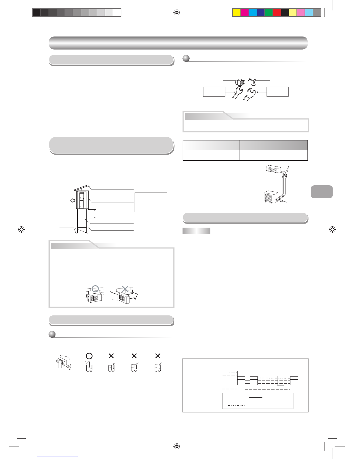
7
ES
UNIDAD EXTERIOR
UNIDAD EXTERIOR
Abocardado
en la unidad
interior
Abocardado
en la unidad
exterior
(Unidad : N•m)
Diámetro externo de tubería
de cobre
Tensamiento de torsión a par
Ø1/4 pulgada (Ø6,35 mm) De 10 a 13 lbf.ft (de 14 a 18 N·m)
Ø3/8 pulgada (Ø9,52 mm) De 24 a 31 lbf.ft (de 33 a 42 N·m)
• Par de apriete para conectar el tubo
abocinado
La presión de R410A es superior a R22.
(Aprox. 1,6 veces más.) Por lo tanto, tense
fi rmemente los tubos abocinados que
conectan la unidad exterior y la unidad
interior con el par de apriete especifi cado
utilizando una llave dinamométrica.
Mitad de la unión
Tuerca
Lado roscado
externamente
Lado roscado
internamente
Utilice una Ilave inglesa
para asegurar.
Utilice una Ilave dinamométrica
para apretar.
PRECAUCIÓN
Alinee los centros de las tuberías de conexión y apriete a fondo la tuerca
con sus dedos. Luego apriete la tuerca con dos llaves inglesas tal como se
muestra en la fi gura.
Apriete de la tubería
No aplique demasiada torsión. De otra manera, la tuerca podría quebrarse
según las condiciones de instalación.
Viento
fuerte
PRECAUCIÓN
1. Instale la unidad exterior en un sitio donde no haya obstrucciones
cerca de su entrada o salida de aire.
2. Cuando la unidad exterior se instala en un lugar que siempre está
expuesto a vientos fuertes como en la costa o en un piso alto de
un edifi cio, utilice un defl ector de viento específi co. Para minimizar
el efecto de los vientos fuertes, especialmente en áreas ventosas,
instale la unidad tal y como se muestra más abajo.
90
Oblicuidad Aspereza Deformación
1. Asegúrese de tener sufi ciente tubería para alcanzar la unidad interior.
2. Corte la tubería con un cortatubos para tubería.
3. Inserte una tuerca y abocine la tubería.
Abocinado
• No utilice la boquilla de drenaje proporcionado para drenar agua. Drene el
agua de los agujeros de drenaje directamente.
• Para proteger la unidad exterior de acumulación de nieve, instale un marco
colgante, y coloque una placa y una tapa de protección contra nieve.
* No utilice ningún diseño amontonado.
Precauciones sobre Instalación en
Regiones con Nieve y Temperaturas Frías
Placa de protección contra nieve
Tapa de protección contra nieve
Línea de acumulación de nieve
Marco colgante
Un mínimo de
19-11/16 pulgada (500 mm)
Instale la unidad por
lo menos a 19-11/16
pulgadas (500 mm)
encima de la línea de
acumulación de nieve.
Pernos de
anclaje
Parte frontal
Locación de Instalación
• Una ubicación que proporcione sufi cientes espacios alrededor de la
unidad exterior tal y como se muestra en el diagrama superior.
• Un situación que pueda resistir el peso de la unidad exterior y que no
permita el aumento del nivel de ruido y vibración
• Un situación en donde el ruido de funcionamiento y el aire descargado no
moleste a sus vecinos
• Una ubicación que no exponga la unidad a vientos fuertes.
• Una ubicación libre de fugas de gases infl amables.
• Un situación que no bloquee un pasaje
• Un lugar en donde el agua drenada no de lugar a ningún problemas
• Dependiendo del nivel de nieve, use un soporte específi co para nieve o
hielo.
• Cuando se vaya a instalar la unidad exterior en una posición elevada,
asegúrese de fi jarla tal y como se describe en la sección superior.
Conección de la Tubería Refrigerante
Conección de Cables
1. INSTALE EL DESCONECTOR DE ALIMENTACIÓN DE LA UNIDAD
EXTERIOR
2.
LLEVE EL CABLEADO DE ALIMENTACIÓN DESDE LA CAJA PRINCIPAL
PARA DESCONECTARLO PARA NEC Y CÓDIGOS LOCALES.
3. Retire la tapa de la válvula, y la abrazadera del cable desde la unidad
exterior.
4. Fije el conector del conducto a la placa del conductor con la tuerca de
fi jación y fíjela fi rmemente.
Conecte la fuente de alimentación y los cables de conexión al bloque
terminal tal y como se muestra en la fi gura en la siguiente página y
asegúrelo fi rmemente con tornillos.
5. No requiere cables adicionales.
6. Fije el cable de alimentación y el cable de conexión con la abrazadera
del cable.
7. Sujete la cubierta de las partes eléctricas y la cubierta de la válvula a la
unidad exterior.
8. LLEVE EL CABLEADO DE CONEXIÓN Y LAS TUBERÍAS A LA UNIDAD
INTERIOR.
Todo el cableado y conexiones han de cumplir con NEC, CEC y códigos
locales.
• Conecte todos los cables a la terminar correcta en los bloques terminales
de cableado.
• Asegúrese de que todos los conectores quedan bien afi anzados.
• Use conectores de los tamaños especifi cados en la sección de requisitos.
• Las interconexiones del sistema deben ser al menos AWG14.
NOTA
L2
L1
L2
L1
SS S
L1 L1 L1
L2 L2 L2
GND GND GND
FUENTE DE ALIMENTACIÓN
DE CAMPO 208/230/1/60
DESCONECTAR POR
NEC Y CÓDIGO LOCAL
UNIDAD
INTERIORUNIDAD EXTERIOR
LEYENDA
DESCONECTAR
POR NEC Y
CÓDIGO LOCAL
Alta tensión de campo y cableado de tierra
Cableado de fábrica
Cableado de señal de campo
CABLEADO DE CONEXIÓN DE CAMPO
1110251291-2 ES.indd 71110251291-2 ES.indd 7 12/17/13 4:58 PM12/17/13 4:58 PM
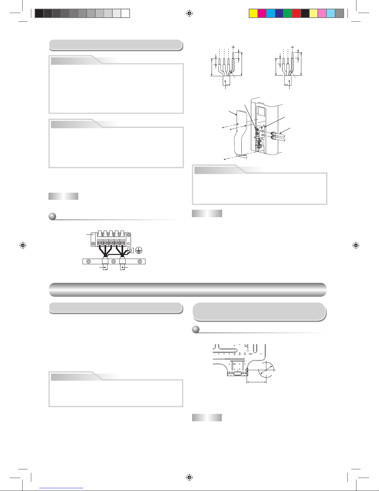
8
Longitud desaislada del cable de suministro de
alimentación y cable de interconexión
NOTA : Cable de interconexión
• Tipo de cable : mínimo AWG14
PRECAUCIÓN
• Las conexiones del cableado incorrecto podrían causar que se caigan
algunas de las piezas eléctricas.
• Asegúrese de que cumple con las NORMATIVAS LOCALES.
• Cada cable deberá conectarse fi rmemente.
• Si se lleva a cabo un cableado incorrecto o incompleto, podría causar
una ignición o humo.
L1
L2
L1
L2
S
Cable de interconexión
Cable de alimentación
Bloque de terminales
Unidad : pulgada (mm)
L1
L2
L1
L2
S
Línea de tierra
Cable de conexión Cable de alimentación
Línea de tierra
3/8 (10)
3/8 (10)
1-3/16 (30)
2-12/16 (70)
3/8 (10)
3/8 (10)
1-3/16 (30)
1-9/16 (40)
Placa del conducto
Conector
Tuerca de fi jación
Cubierta de
válvula
UNIDAD INTERIOR
UNIDAD INTERIOR
Locación de Instalación
Corte de un Orifi cio y Montaje de la
Placa de Montaje
NOTA
• Cuando la perforación de una pared que contenga listones, listones de
alambre o placas de metal, asegúrese de utilizar una sierra de corona.
Corte de un orifi cio
Cuando instale las tuberías refrigerantes desde la parte posterior
Después de determinar la posición del orifi cio de la tubería con la placa de
montaje (
➡), perfore el orifi cio de la tubería Ø2-9/16 pulgada (Ø65 mm)
ligeramente inclinado hacia abajo al lado exterior.
• Una ubicación que proporcione sufi cientes espacios libres alrededor de
la unidad interior tal y como se muestra en el diagrama en la sección
“ESPACIOS LIBRES”.
•
Un situación en el que no haya obstáculos cerca de la entrada y salida de aire
•
Un situación que permita una instalación fácil de la tubería para la unidad
exterior
• Un situación que permita que el panel delantero se abra
• La unidad interior debe instalarse de tal modo que la parte superior de la
unidad interior llegue al menos a los 6,6 pies (2 m) de altura. Evite también
poner cualquier cosa sobre la parte superior de la unidad interior.
• Una ubicación que soportará el peso de la unidad.
PRECAUCIÓN
• Se deberá evitar la luz directa del sol sobre el receptor de control a
distancia de la unidad interior.
• El microprocesador de la unidad interior no deberá estar tan cerca de
las fuentes de ruido RF.
(Para los detalles, vea el manual del usuario.)
80 100 180
El orifi cio del centro de
la tubería está sobre
la lecha.
Orifi cio de
la tubería
Ø2-9/16 pulgada (65 mm)
3-15/16 pulgada
(100 mm)
1. La tensión de alimentación debe ser la misma que la tensión nominal del
aire acondicionado.
2. Prepare la fuente de alimentación para un uso exclusivo con el aire
acondicionado.
NOTA : Cable de alimentación
• Tipo de cable : mínimo AWG14
PRECAUCIÓN
RIESGO DE DAÑO AL EQUIPO
En caso de no seguir esta advertencia puede provocar daños al equipo
o un funcionamiento inadecuado.
La avería de la unidad como resultado de una aplicación inadecuada
de la tensión de red o un excesivo desequilibrio de fase, constituye un
abuso y puede provocar daños a los componentes eléctricos. Este tipo
de uso puede anular cualquier garantía aplicable.
Trabajo Eléctrico
ADVERTENCIA
RIESGO DE DESCARGA ELÉCTRICA
En caso de no seguir esta advertencia puede sufrir daños personales o
incluso la muerte.
La carcasa de la unidad debe tener una conexión directa a tierra para
minimizar el riesgo de daños personales si ocurriera un fallo eléctrico.
La conexión a tierra debe estar realizada por un cable o conductor
metálico que cumpla con las normativas eléctricas aplicables.
Asegúrese de que el interruptor de alimentación principal está
APAGADO antes de realizar una reparación o mantenimiento.
1110251291-2 ES.indd 81110251291-2 ES.indd 8 12/17/13 4:58 PM12/17/13 4:58 PM
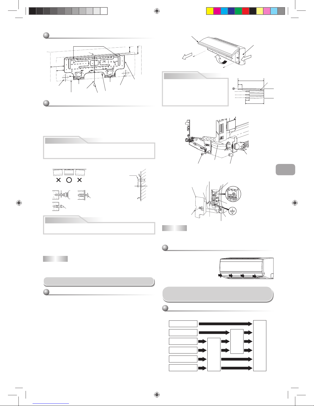
9
ES
Montaje de la placa de montaje
1
7
Orifi cio del perno de anclaje
Gancho
Gancho
Gancho
Orifi cio de
la tubería
Orifi cio de
la tubería
Placa de
montaje
Tornillo de montaje
Peso
Unidad interior
Hebra
A 6,6 pies. (2 m) como
mínimo del suelo
7 pulgada
(170 mm)
3-11/32 pulgada
(85 mm)
2-29/64 pulgada
(62 mm)
3-17/64 pulgada
(82,5 mm)
7
Placa de instalación
(Mantenga la posición horizontal.)
Orifi cio, 3/16 pulgada (5 mm) diá
Tornillo de montaje
Ø5/32 pulgada × 1 pulgada
(Ø4 mm × 25 mm)
Perno de anclaje
Proyección
9/16 pulgada (15 mm)
o menos
PRECAUCIÓN
NOTA
• Fije las cuatro esquinas y partes inferiores de la placa de montaje con 4 u
6 tornillos de montaje.
PRECAUCIÓN
Si no instala fi rmemente la unidad podría causar daños personales o
materiales.
Conección de Cables
1. Tire hacia arriba para abrir la rejilla de entrada de aire.
2. Retire los tornillos que aseguran el panel frontal.
3. Abra ligeramente la parte inferior del panel frontal y tire hacia usted de la
parte superior para extraer el panel de la placa posterior.
4. Inserte la tubería conductora (según los códigos locales) en el agujero
de la tubería en la pared.
5. Retire el montaje del conducto para cables afl ojando el tornillo de fi jación
(Fig. 1)
6. Fije el tubo de conducto para cables en el montaje de conducto con la
tuerca de fi jación.
7. Coloque el cable de conexión a través de la tubería del conducto y
procese el cable. (Fig. 3)
8. Retire el cable por la parte frontal y fíjelo al bloque terminal.
Tenga cuidado de que no le falte cable. (Fig. 2)
9. Fije fi rmemente los tornillos terminales para evitar que se afl ojen. Par
de apriete: 0,9 lbf.ft (1,2 N·m). Después de fi jarlos, tire de los cables
ligeramente para asegurarse de que no se muevan.
10. Fije el cable de conexión con la abrazadera para cable.
11.
Fije el montaje del conducto para cable de nuevo al cuerpo fi jando un tornillo.
12. Fije el panel frontal, la cubierta terminal y la rejilla de entrada de aire en
la unidad interior.
Cómo conectar el cable de conexión
S
L
2
L1
Línea
de tierra
4-5/16 pulgada (110 mm)
3-5/32 pulgada (80 mm)
13/16 pulgada (20 mm)
3/8 pulgada (10 mm)
Fig. 3
Fig. 1 Montaje
Fig. 2 Cableado
L
1
L
2
S
L
1
L
2
S
Cable con abrazadera
Bloque de terminales
Cubierta del terminal
Tornillo
Línea de tierra
Tornillo
Cable de conexión
Tornillo
Panel frontal
NOTA
• Utilice sólo cable trenzado.
• Tipo de cable : mínimo AWG14.
Cuando instale la placa de montaje con un tornillo de montaje no utilice el
orifi cio del cerrojo de áncora. Si no, la unidad se podría caer y resultar en
daños personales y en daños de propiedad.
3
1
2
Rejilla de entrada de aire
Panel frontal
Tubería de conducto
para cables
Montaje del
conducto
Tornillo de fi jación
Tuerca de
fi jación
Cable de
interconexión
Cuando la placa de montaje se monta
directamente en la pared
1. Para enganchar la unidad interior, fi je de forma segura la placa de montaje
sobre la pared atornillándola en las partes superior e inferior.
2. Para montar la placa de montaje en una pared de hormigón con tacos,
taladre los agujeros de los pernos de anclaje tal y como ilustra la fi gura que
se muestra más abajo.
3. Asegúrese de que la placa de montaje está a nivel.
Gancho de anclaje
(piezas suministradas específi camente)
• En el caso de que la unidad se vaya a instalar en una pared de bloque,
ladrillo, hormigón o similar, haga agujeros en la pared de 3/16 pulgadas
(5 mm) de diámetro.
• Inserte tacos para tornillos de montaje 7 apropiados.
PRECAUCIÓN
• Asegúrese de consultar el diagrama de
cableado del sistema situado dentro del
panel frontal.
• Compruebe los códigos eléctricos
locales y también cualquier instrucción
o limitación del cableado específi ca.
AISLE AMBAS LÍNEAS.
Formación la tubería y el tubo de desagüe
Posterior derecho
Posterior izquierdo
Inferior izquierdo
Izquierdo
Inferior derecho
Derecho
Tapa precortada
Cambio del tubo
de desagüe
Preparación de la tubería
Instalación de Tubería y el
Tubo de Desagüe
Procedimiento para instalar la rejilla de entrada
de aire en la unidad interior
• Cuando coloque la rejilla de entrada
de aire, realice el mismo proceso
para retirarla pero en orden inverso.
1110251291-2 ES.indd 91110251291-2 ES.indd 9 12/17/13 4:58 PM12/17/13 4:58 PM
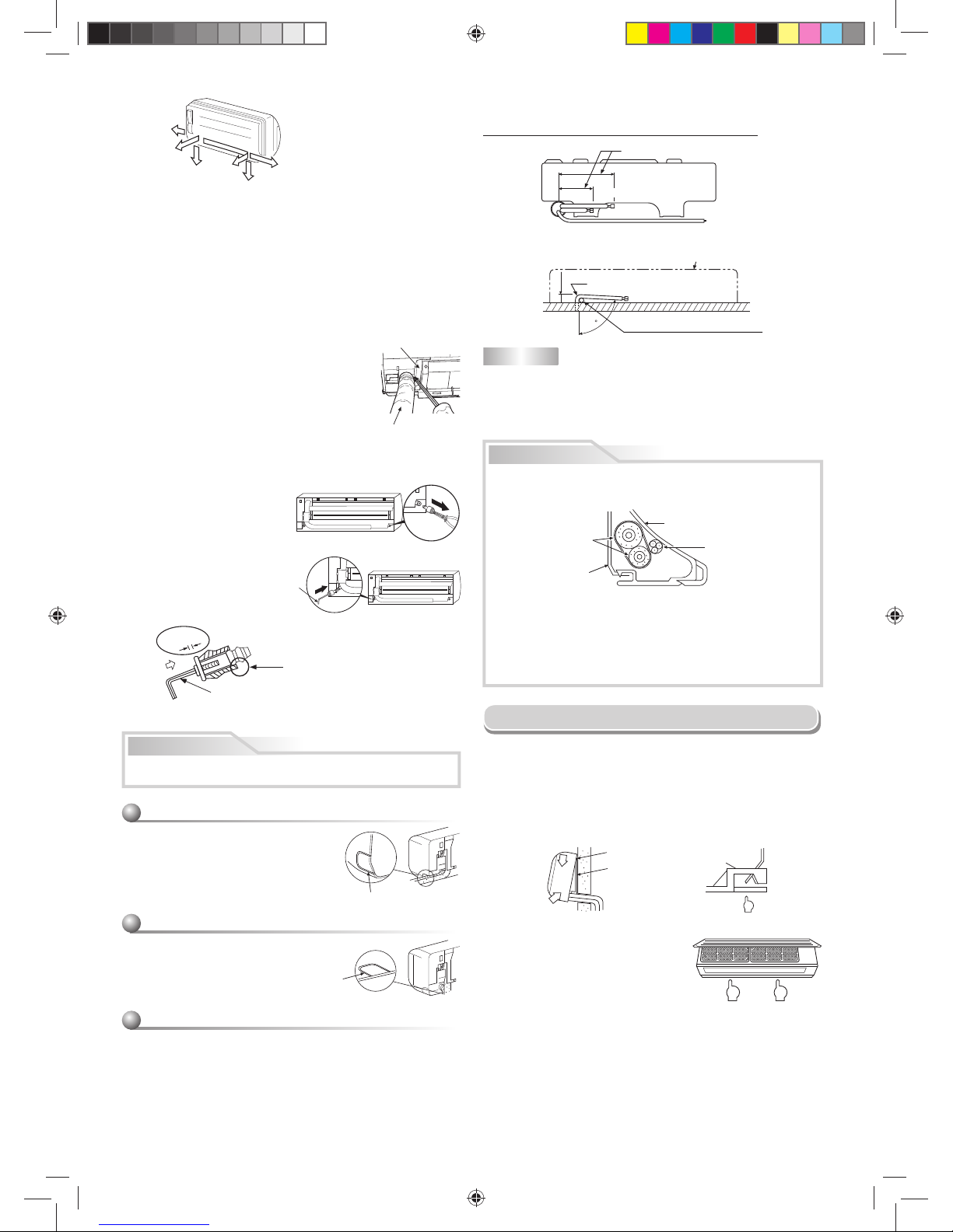
10
80
Lado líquido
Lado de gas
(Al lado del frente del destello)
Contorno de la unidad interior
R 1-3/16 pulgada (R 30 mm) (Utilice
polisin (núcleo de polietileno) o similar
para tubería fl exible.)
Utilice la manija del destornillador, etc.
6-11/16 pulgada
(170 mm)
1-5/8 pulgada
(43 mm)
10-5/8 pulgada
(270 mm)
Doble la tubería de conexión dentro de un radio de 1-3/16 pulgada
(30 mm).
Para conectar la tubería después de instalar la unidad (fi gura)
1. Tapa precortada
Haga una hendidura con unos alicates en los lados izquierdo y derecho del
panel frontal para la conexión desde la izquierda o derecha respectivamente
y la hendidura en el lado inferior izquierdo o derecho del panel frontal para la
conexión inferior izquierda o derecha.
2. Cambio del tubo del desagüe
Para los desagües de las conexiones izquierda, inferior izquierda y posterior
izquierda, es necesario cambiar el tubo y la tapa del desagüe.
Para evitar pérdidas de agua, inserte con fi rmeza el tubo y la tapa del
desagüe.
PRECAUCIÓN
Cómo quitar la manguera de drenaje
• La manguera de drenaje se puede retirar quitando
el tornillo que fi ja la manguera de drenaje y a
continuación estirando la manguera de drenaje.
• Cuando quite la manguera de drenaje, tenga
cuidado con cualquier borde afi lado que pueda
tener la placa de acero. Los bordes afi lados
pueden provocar daños.
• Para instalar la manguera de drenaje, inserte
fi rmemente la manguera de drenaje hasta que la
pieza de conexión haga contacto con el aislante
térmico y fíjelo con los tornillos originales.
Forma de fi jar el tapón de desagüe
1) Inserte una llave inglesa
hexagonal 3/16 pulgadas
(4 mm) en el centro de la
cabeza de la tapa.
Aislante térmico
Manguera de drenaje
3/16 pulgada
(4 mm)
Para las tuberías derecho o izquierdo
• Después de rajar el panel frontal con un
cuchillo o un punzón, córtelos con un
par de tijeras o una herramienta similar.
Para las tuberías inferior derecho o inferior
izquierdo
• Después de rajar el panel frontal con un
cuchillo o un punzón, córtelos con un
par de tijeras o una herramienta similar.
Conexión del lado izquierdo de la tubería
• Doble la tubería de conexión de tal manera que quede tendida entre 1-5/8
pulgada (43 mm) sobre la superfi cie de la pared. Si la tubería de conexión
está tendida sobrepasando las 1-5/8 pulgadas (43 mm) por encima de la
superfi cie de la pared, la unidad interior puede estar inestable en la pared.
Cuando doble la tubería de conexión, asegúrese de usar un resorte
curvador para evitar aplastar la tubería.
Corte
Corte
Cómo quitar la tapa de drenaje
Sujete la tapa de drenaje con
unos alicates de punta de aguja
y sáquela.
No utilice aceite lubricante (aceite para
maquinaria refrigerante) al insertar la tapa del
desagüe. La aplicación causa deterioración y
fuga de drenaje del enchufe.
Inserte una llave
hexagonal 3/16 pulgada
(4 mm).
Sin
espacio
2) Inserte fi rmemente el tapón de desagüe.
NOTA
Si se dobla la tubería de forma incorrecta, la unidad interior puede estar
inestable en la pared.
Después de pasar la tubería de conexión a través del orifi cio de la tubería,
conecte la tubería de conexión a las línea de refrigerante y envuelva con
cinta para cubrir alrededor de las mismas.
PRECAUCIÓN
• Encinte las líneas de refrigerante (dos) y el cable de conexión
fuertemente. En caso de tubería por el lado izquierdo y por el lado
posterior izquierdo, encinte solamente las líneas de refrigerante (dos).
Unidad interior
Cable de conexión
Líneas de refrigerante
Placa de instalación
• Ordene las tuberías con cuidado de tal modo que ninguna sobresalga
de la placa trasera de la unidad interior.
• Conecte cuidadosamente las líneas de refrigerante y las tuberías de
conexión a cada una y corte la cinta aisladora en la tubería de conexión
para evitar la doble cinta en la unión, además, selle la unión con cinta
de vinilo, etc.
•
Compruebe que no hay fugas de gas antes de aislar.
Presionar
Presionar
1
2
1
Pulse
(desenganchar)
Gancho aquí
Placa de instalación
Gancho
Instalación de la Unidad Interior
• Para separar la unidad interior de la placa
de montaje, tire de la unidad interior hacia
usted mientras empuja su parte inferior
hacia arriba, tal y como se muestra en la
fi gura.
1. Pase la tubería a través del agujero en la pared y enganche la unidad
interior en el gancho superior de la placa de instalación.
2. Oscile la unidad interior de derecha a izquierda para confi rmar que está
enganchada fi rmemente a la placa de montaje.
3. Mientras presiona la unidad interior hacia la pared, engánchela a la
sección inferior de la placa de montaje. Tire de la unidad interior hacia
usted para confi rmar que está enganchada fi rmemente a la placa de
montaje.
Derecho
Posterior
derecho
Inferior
derecho
Posterior
izquierdo
Inferior izquierdo
Izquierdo
1110251291-2 ES.indd 101110251291-2 ES.indd 10 12/17/13 4:58 PM12/17/13 4:58 PM
 Loading...