

SERVICE MANUAL
ROOM AIR-CONDITIONER
PORTABLE TYPE
FILE NO. A00-9607
RAC-08EW-E
PRINTED IN JAPAN Mar., 1996 S

– 2 –
CONTENTS
1. SPECIFICATIONS..............................................................................................................3
2. SPECIFICATIONS OF ACCESSORIES ............................................................................. 3
3. APPEARANCE ................................................................................................................... 4
4. SPECIFICATIONS OF ELECTRICAL PARTS .................................................................... 4
5. WIRING DIAGRAM (RAC-08EW-E) .................................................................................. 5
6. COOLING CHARACTER CHART ...................................................................................... 6
7. REFRIGERATING CYCLE DIAGRAM.............................................................................. 7
8. MICROCOMPUTER BLOCK DIAGRAM ............................................................................ 8
9. OPERATION DESCRIPTIONS........................................................................................... 9
9-1. Operation Control Knobs on Control Panel ........................................................................................ 9
10. OUTLINE OF OPERATIONS .......................................................................................... 10
10-1. Basic Operation................................................................................................................................ 10
10-2. Economy Mode ................................................................................................................................ 10
10-3. Dry Mode ..........................................................................................................................................11
10-4. Economy Operation ..........................................................................................................................11
11. TROUBLESHOOTING CHART ...................................................................................... 1 2
11-1. What to be Prechecked First............................................................................................................ 12
11-2. How to Judge Faulty Parts by Symptoms ........................................................................................ 13
11-3. PC Board Layout .............................................................................................................................. 22
12. INSTALLATION INSTRUCTION..................................................................................... 24
12-1. Installation Method ........................................................................................................................... 24
12-2. Routine Maintenance ....................................................................................................................... 24
12-3. Water Supply.................................................................................................................................... 24
12-4. Changing of Water ........................................................................................................................... 25
12-5. Relocation of Air Conditioner ............................................................................................................ 25
13. CLEANING METHOD OF CONDENSER....................................................................... 26
13-1. Condenser Servicing Procedures..................................................................................................... 26
14. EXPLODED VIEWS AND PARTS LIST .......................................................................... 27
Note:
A special tool is required to remove the back cabinet.
(In EXPLODED VIEWS AND PARTS LIST, Location No. 256 “Screw Driver”)
– 3 –
Height
Width
Depth
Frequency
Rated voltage
Cooling capacity
Airflow, high
Moisture removal
Running current
Power consumption
Power factor
Model, output
Model
mm
mm
mm
kg
Hz
V
kW
m3/h
lit/h
A
W
1. SPECIFICATIONS
Item
Dimensions
Net weight
Power source
Standard
performance
Electrical
characteristics
Compressor
Condenser
Evaporator
Safety devices
Fan motor
Refrigerant
Air filter
Power cord
Accessories
720
500
315
35
50
1 phase, 220/230/240
2.10/2.18/2.18
390/400/410
1.2
3.82/3.80/3.85
780/800/840
93/92/91
PH94X1-4G1, 750W
Ripple tube type, Forced air ventilation
Finned tube type, Aircooled ventilation
Finned tube type, Aircooled ventilation
Float switch, Over current relay
20W, Induction motor
R-22, (Charged quantity, 0.47 kg)
Polypropylene net filter
3-core (One core for grounding),
1.9 m (6.4 ft) length with plug
Exhaust hose, Caster seat, Exhaust hole,
Cap for exhaust hole
RAC-08EW-E
(for indoor and exhaust)
Specifications are subject to change without notice.
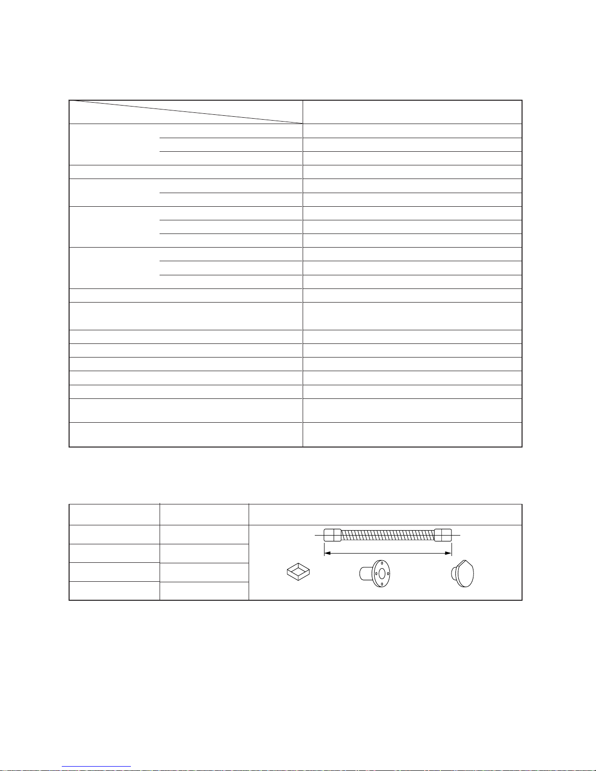
2. SPECIFICATIONS OF ACCESSORIES
Item
Exhaust hose
Caster seat
Exhaust hole
Cap for exhaust hole
Remarks
Q'ty
1
4
3
3
1.4m
C
aster seat Exhaust hole Cap for exhaust hole

– 4 –
3. APPEARANCE
Fig. 3-1
4. SPECIFICATIONS OF ELECTRICAL PARTS
315mm
(12.4 in)
500mm (19.7 in)
Wind direction
control grille
(horizontal)
Air outlet
Wind direction
control grille
(Vertical)
Caster
420mm (16.5 in)
Front door
Water tank
720mm (28.3 in)
Front panel
Control panel
Operation switch
(ON/OFF)
Economy switch
230mm
(9.1in)
Sub cabinet
Back cabinet
Handle
Holder of
power cord
Power cord
(220/240V)
1.9m (6.4ft)
39mm
(1.5 in)
120mm
(4.7 in)
(1.8 in)
45.5mm
285mm
(11.2 in)
Drain hose
Case of hose
Connector of
exhaust hose
Air inlet
Air filter
Specifications
Single phase, 50 Hz, 220/230/240V ~, AC. 750W output
Winding resistance
(Ω) (at 20°C)
Single phase, 50 Hz, 230V, AC. 20W output
Winding resistance
(Ω) (at 20°C)
400V, 20µF (for compressor)
500V, 1µF (for fan motor)
250V, 3A (for fan motor)
250V, 15A (for compressor)
Rated current, 0.1A 100V DC
Primary 220V ~ 240V, Secondary 12.3V ~ 13.6V
Differential ±2°C, Adjustable range 17 ~ 28°C
Differential ±2°C
Copper wire minimum 1.0 mm
2
6.3A
Parts name
Compressor
Fan motor
Running capacitors
Relay
Float switch
Transfor mer
Microcomputer
Room temperature sensor
(Ta-sensor)
Heat-exchanger sensor
(Tc-sensor)
Power supply cord with plug
Fuse
Red-White
13.1
Type
PH94X1-4G1
STF-230-20-4C
EARU40M206UF
EEP2H105HWNB05
AJE6412
PC12D2
FS-085-002F
FT67-2
TMP47C440AN
(Microcomputer)
(Microcomputer)
TSCR
Red-Black
4.55
White-Black
8.55
Black-Orange
102.5
Orange-Blue
111.1
Black-Orange
145.9
Red-Black
205.0
– 5 –
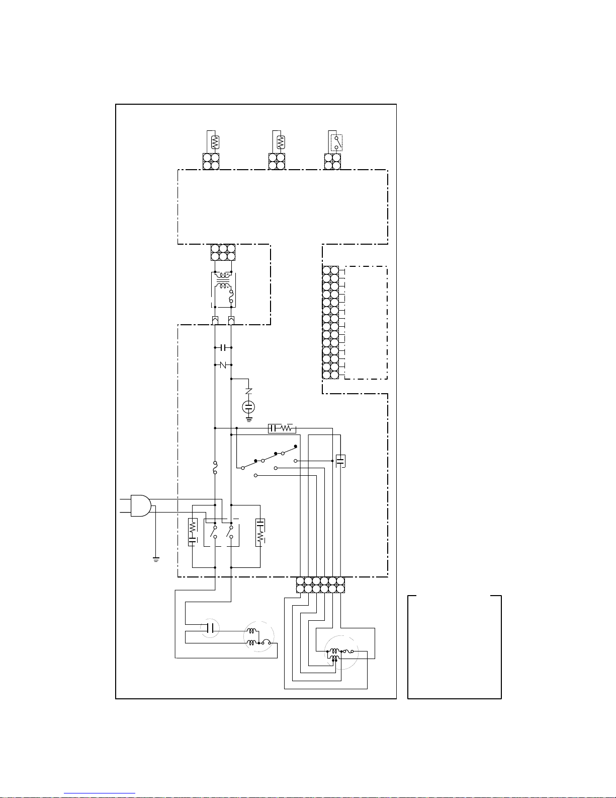
5. WIRING DIAGRAM (RAC-08EW-E)
Fig. 5-1
1
2
3
4
5
6
7
8
9
10
11
12
13
14
1
2
3
4
5
6
7
8
9
10
11
12
13
14
OPERATION
PANEL
PC BOARD
CN06
112
2
12
12
12
12
HEAT
EXCHANGER
SENSOR
THERMO SENSOR
(ROOM TEMPERATURE)
FLOAT
SWITCH
CN05CN04CN02
12123
3
CN01
CONTROL
PC BOARD
WHI RED
BLU BLU
TRANSFORMER
VARISTOR
F01
FUSE
6.3A
C35
1
234
5
6
1
234
5
6
CN03
COMPRESSOR
RUNNING
CAPACITOR
RED
BLK
WHI
RED
BLK
CR01
RY07
RELAY
423
1
FAN MOTOR
WHIBLK
ORN
BLU
GRY
RED
CR03
RY01
RY02
RY03
RUNNING
CAPACITOR
SINGLE
50Hz
220/230/240V~
BLU
BRW
GRN&YEL
GRY
BRW
WHI
BLK
RED
BLU
GRN &YEL
ORN
:
:
:
:
:
:
:
:
GRAY
BROWN
WHITE
BLACK
RED
BLUE
GREEN &
YELLOW
ORANGE
Color Identification
R26
VARISTOR
SURGE
ABSORBER
DSA
CR02
CN08 CN07
– 6 –
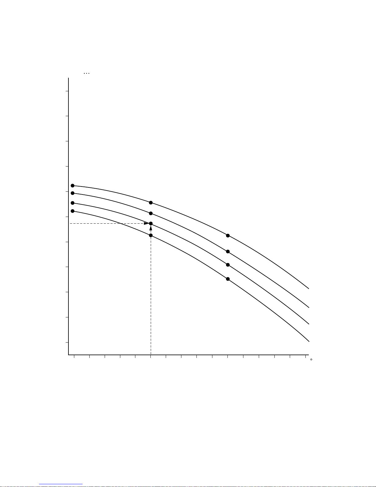
6. COOLING CHARACTER CHART
Fig. 6-1
Humidity
2.7
32 31 30 29 28 27 26 25 24 23 22 21 20 19 18 17 C
Ambient temperature
Cooling Capacity kW
40%
50%
60%
70%
2.6
2.5
2.4
2.3
2.2
2.1
2.0
1.9
1.8
1.7
– 7 –
Conditions
Surface temp. of heat exchanger
interchanging pipe (°C)
T
1
10
17
5
Outdoor
35/24
43/26
21/15
Ambient temp.
conditions DB/WB (°C)
Indoor
27/19
32/23
21/15
T
2
50
57
34
Cooling
Standard
High temperature
Low temperature
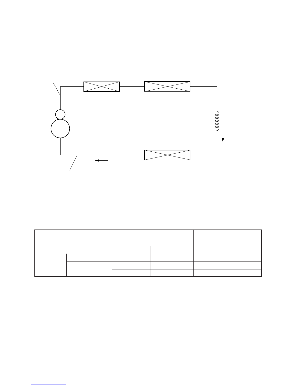
7. REFRIGERATING CYCLE DIAGRAM
RAC-08EW-E
Fig. 7-1
RAC-08EW-E
Table 7-1
Note:
Measure the heat exchanger temperature at the center of U-bend. (By means of thermistor thermometer.)
Capillary tube
I.D : 1.2 mm
O.D : 2.04 mm
Length : 400 mm
Evaporator
T1
Suction tube
I.D : 6.8 mm
O.D : 8.0 mm
Compressor
Sub condenser (air)
Delivery tube
I.D : 4.8 mm
O.D : 6.0 mm
Main condenser (Water)
T2
– 8 –
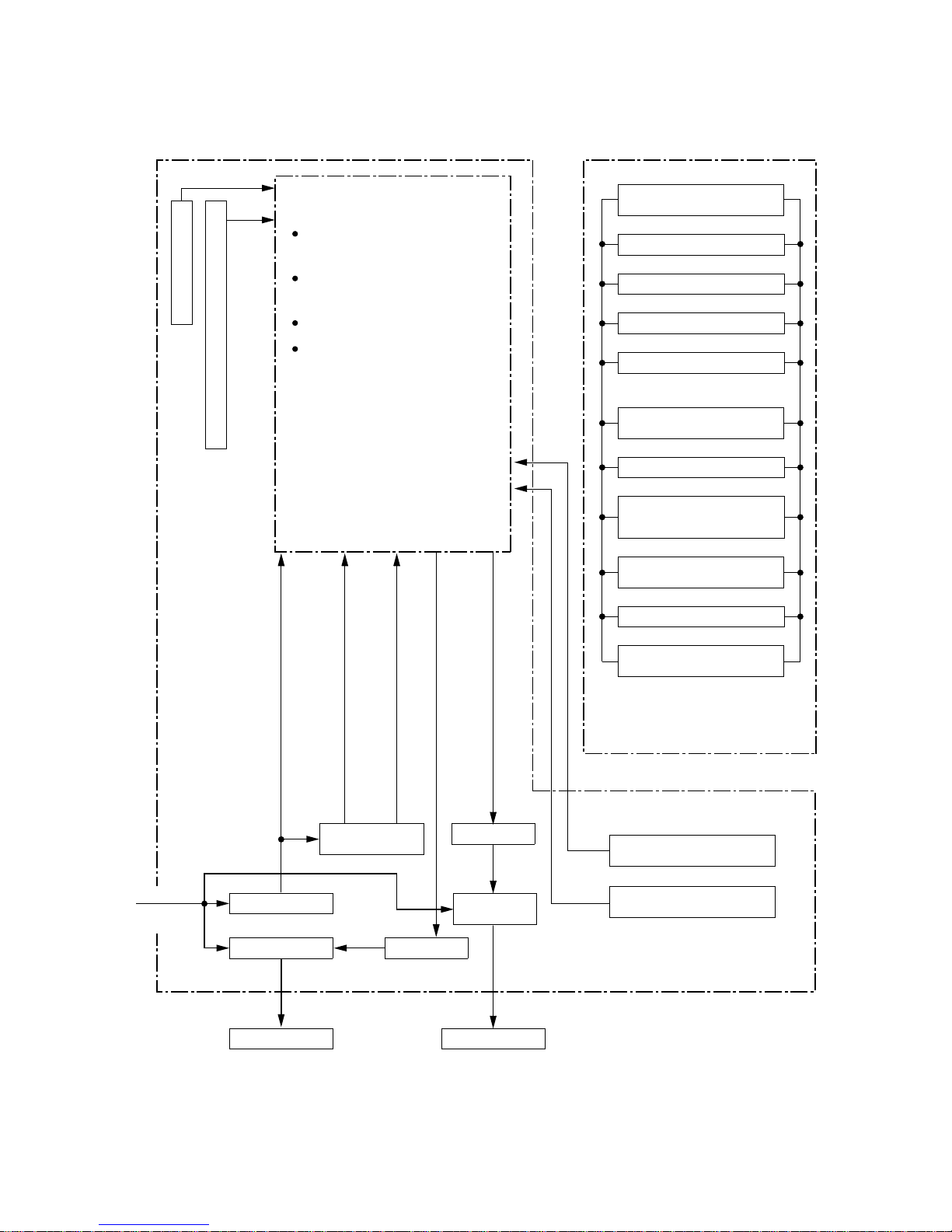
8. MICROCOMPUTER BLOCK DIAGRAM
Fig. 8-1
Functions
3-minute delay at Restart for
compressor
Start-up Compensation for fan
motor
Timer
Processing
(Temperature processing)
Clock frequency oscillator circuit
Initializing circuit
C.P.U.
Mode selector
(Cool/Dry/Fan only)
Operation indicator
Economy indicator
Economy indicator
Warning indicator
Timer selector (ON,
CONTINUE, OFF)
Timer setting
Air flow selection
(Fan selector High,
Low, AUTO)
Operation
(ON/OFF)
Temperature setting
Economy selection
(ON/OFF)
Room temperature sensor
(Ta sensor)
Power supply
circuit
Relay driver
Miniature
relay
Relay driver
Transformer
Power relay
Heat-exchanger sensor
(Tc sensor)
AC input
DC 12 volt
DC 5 volt
Compressor ON/OFF signal
Fan motor signal
Compressor
Fan motor
Control unit
Remote control unit
AC 50Hz
220/230/
240V
A bold line denotes a 220/230/240V AC line.
– 9 –
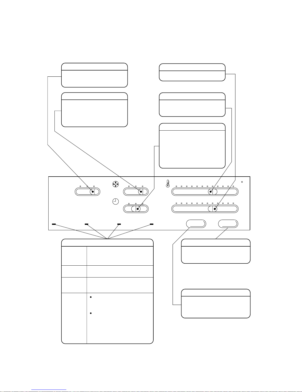
9. OPERATION DESCRIPTIONS
9-1. Operation Control Knobs on Control Panel
Fig. 9-1
FAN ONLY DRY:COOL
MODE FAN SPEED
TIMER SELECT
HIGH LOW:AUTO
OFF CONT. ON
WARNING TIMER ECONOMY OPERATION
TIMER
THERMO
ECONOMY I/O
2 4 6 8 10 12 Hr.
18 20 22 24 26 28 C
RAC-08EW-E
This lamp will light up during the
COOL, DRY, or FAN ONLY
operation. It begins flashing if a
power failure occurs.
This lamp will light up when you
push the ECONOMY button.
This lamp will light up when the
TIMER SELECT knob is set to ON or
OFF.
This lamp will light up when the
water in the tank runs out. When
the tank is refilled, the lamp will go
off.
The red lamp flashes during abnormal
operation. To turn off the lamp, push
the ON/OFF button.
Waiting about five minutes, push the
button again, the OPERATION lamp
will light up and the air conditioner
will start operating.
Lamps
OPERATION
(green)
ECONOMY
(green)
TIMER
(yellow)
WARNING
(red)
I/O button
Push this button to start the air
conditioner, push it again to stop it.
ECONOMY button
Push this button to start the
economy operation, push it again to
cancel the economy operation.
Upon expiry of the number of hours
set using the TIMER knob, the
air conditioner starts operating if the
knob is set at ON or stops operating
if the knob is at OFF.
With the knob set at CONT., the air
conditioner continues operating
regardless of the TIMER setting.
TIMER SELECT knob
The AUTO position automatically
changes the fan speed according to
room temperature.
During DRY and ECONOMY mode,
LOW is used regardless of the setting.
FAN SPEED knob
MODE knob
Use to select the operation mode
COOL, DRY, or FAN ONLY.
THERMO knob
The scale gives just a rough mesure
of the temperature setting.
Set to a desired time.
TIMER knob
– 10 –
10. OUTLINE OF OPERATIONS
10-1.Basic Operation
(1) When I/O button is pushed, the relays RY01,
RY02 or RY03 and power relay RY07 start according to the conditions set by F AN SPEED knob
selector switch. Thus, the indoor fan motor and
compressor are controlled. (Operations as described in this paragraph are all programmed. And
following items are same as it.)
(2) When the I/O button is pushed again, the relays
are all disabled, and the air conditioner stops.
(3) When the I/O button is pushed with the timer set
at any desired time, the relays are all disabled
and the air conditioner stops when the timer
reaches the set time. However, if the operation
is started with the timer set to “CONTINUE”, the
operation continues.
(4) To adjust the room temperature, set the knob
mounted on the control panel at desired temperature. The room temperature sensor detects and
controls the adequate temperature.
(5) When the FAN SPEED selector switch is set to
“AUTO”, the volume of air is controlled to be felt
agreeable.
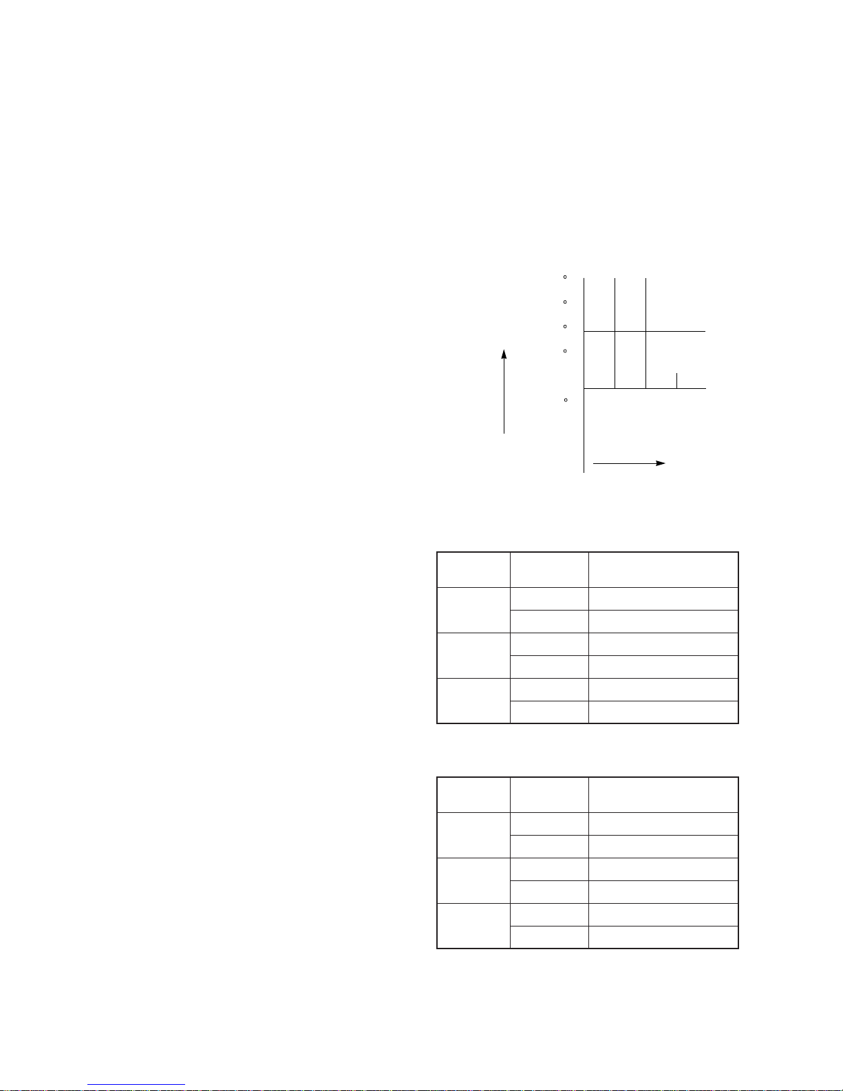
10-2. Economy Mode
This control mode establishes some zones corresponding to different combinations of on and off intervals of the compressor and selects a suitable zone
depending on the lapse of time from the start of operation and the temperature.
Fig. 10-1
Table 10-1 During cooling
Table 10-2 During drying
+4 C
+3 C
+2 C
+1 C
Setting temp.
-1 C
Zone B
Zone D
Zone F
Zone A
Zone C
Zone E
1H 2H 3H
Monitoring
(when room temperature
is not higher than the
set temperature)
Time
Room
temperature
Lapse from
start
0 to 1 hour
1 to 2 hours
2 hours ~
Zone
A
B
C
D
E
F
Compressor
ON OFF 18 – 4 minutes
ON OFF 3 – 4 minutes
ON OFF 5 – 7 minutes
ON OFF 3 – 7 minutes
ON OFF 5 – 10 minutes
ON OFF 3 – 10 minutes
Lapse from
start
0 to 1 hour
1 to 2 hours
2 hours ~
Zone
A
B
C
D
E
F
Compressor
ON OFF 5 – 4 minutes
ON OFF 3 – 4 minutes
ON OFF 5 – 7 minutes
ON OFF 3 – 7 minutes
ON OFF 5 – 10 minutes
ON OFF 3 – 10 minutes

– 11 –
10-3. Dry Mode
In this mode, a microcomputer control lowers humidity while maintaining a constant temperature. The
microcomputer turns the compressor on and off at
regular intervals (3 to 6 minutes on and/or off). During the halt, the airflow fan stops as well.
The compressor and airflow fan will operate independent of the temperature control, though the pattern
of operation depends on the relation between room
temperature (TA) and set temperature (Ts), as shown
below:
Table 10-3
10-4. Economy Operation
(1) When the economy button is pushed, the
economy lamp is lit and the economy operation
will start. (But this operation will not start in the
mode of fan only.)
(2) The economy operation with the cooling and dry
modes will be performed in the manner as stated
below.
10-4-1. Cooling Operation
(1) The compressor will be operated by means of
ON/OFF interval operation.
(2) The room fan will be controlled as stated below:
• When compressor is turned on: L
• When compressor is turned off: UL
• When monitoring: OFF
(3) An interval operation will be started from OFF
time. But when starting operation, it will be kept
in ON position for 6 minutes.
Fig. 10-2
10-4-2. Dry Operation
(1) ON/OFF interval operation both of the compres-
sor and fan will be performed (At the OFF time,
both of the compressor and fan will be set to
OFF.)
(2) Wind capacity is of L.
(3) An interval operation will be performed in Ta ≥ Ts
condition.
10-4-3. Fan Operation
(1) When operation change over switch is set to fan
operation, the economy operation shall not be
executed. And the economy lamp shall not be lit
too. (Normal fan operation will be performed.)
Fig. 10-3
minutes
Stop Stop Stop Stop
Stop Stop Stop Stop
Low Low Low Low
ab6
Compressor
Airflow fan
Room temperature (TA) measurement timing
Time
The airflow fan will operate in the Low position, independent of the position of
the airflow settin
g
control.
18 min ON
-4 min OFF
5 min ON
-7 min OFF
3 min ON
-4 min OFF
3 min ON
-7 min OFF
5 min ON
-10 min OFF
3 min ON
-10 min OFF
Monitoring (Compressor, OFF. Fan, OFF)
Ta
+3
+2
+1
T
s
12
Time
Relation between
room temp. (T
A
) and
set temp. (TS)
TA > TS + 2
TS + 2 > TA > T
S
TS > T
A
OFF
period
a
4 min.
5 min.
6 min.
ON
period
b
6 min.
5 min.
3 min.
– 12 –
Operation of air conditioner
When the POWER plug socket of the unit is
inserted, the operation lamp on the control panel
flashes.
Room temperature is in the range under which the
compressor is turned on and the operation lamp is
lighting, but the compressor will not start.
Fan speed remains unchanged when the fan speed
knob is operated in the dry mode.
The indoor fan occasionally stops intermittently in
the dry mode.
The compressor will not switch on or off even when
the Thermo control is operated in the dry mode.
Warning lamp is lit and no cold air comes out.
Warning lamp blinks and no cold air comes out.
At the mode of fan only, the economy lamp is not lit
when the economy button is pushed.
The push button has not returned when the
economy button is pushed.
11. TROUBLESHOOTING CHART
Troubleshooting procedures:
• Following the details of “What to be prechecked first”, make sure of the basic items.
• When there is no trouble corresponding to above, check in detail the faulty parts following “How to judge
faulty parts by symptoms” later.
11-1.What to be Prechecked First
11-1-1. Power Voltage
The power voltage must be from AC 198V to 264V. If
the power voltage is not within this range, the air conditioner may not work normally.
11-1-2. Operations not Regarded as Failure
(Program Operation)
In terms of the control of air conditioner, the operations shown in Table 11-1 are made as a program
operation incorporated in a microcomputer. If a claim
is made about the operation, check it corresponds to
the contents in Table 11-1. If it does, it is an indispensable operation for the control and maintenance
of the air conditioner but not a failure of the units.
• Operations which are not deemed trouble
Table 11-1
Description
The operation lamp flashes indicating that power is turned on.
If this happens, push the I/O button once, and flash will stop.
Power failure also causes the same lamp to flash.
The compressor will not start while the compressor restart
prevention timer (three-minute timer) is actuated. This applies
also when power is turned on.
Fan speed is fixed at Low in the dry mode.
In the dry mode, the fan operation is synchronized with the
compressor. As a result the fan is stopped when the compressor is stopped.
In the dry mode, the compressor goes on and off at regular
intervals independent on the Thermo control.
When water in the tank has been drained out, stop the
operation of the compressor for safety. Fill the water in the
tank.
When the temperature in the freezing cycle (high pressure
side), stop the operation of the compressor for safety. Be sure
that the exhaust port has plugged with something or water is
not remain in the exhaust hose.
In case of the fan only mode, the economy lamp will not be lit
since the economy control will not be performed.
The economy button is of lock type. When the button is
pushed again, the button is set to OFF and the button will
come out. The operation button will come out all the time since
it is not of lock type.

– 13 –
11-2.How to Judge Faulty Parts by Symptoms
One of the most important matters for the repair of air conditioners is accurate trouble analysis.
For this purpose, it is required to make a correct judgement about the problem by asking the user.
11-2-1. Trouble A nalysis Classification
Trouble
analysis
classification
Totally
inoperable
Some parts are
inoperable.
Operable but
abnormal.
1 Unit is inoperable.
2 Breaker or fuse blows out.
3 Only fan does not work.
5 Compressor does not operate.
6 Unit repeats ON/OFF frequently. Short cycles.
7 Cooling is not obtained or insufficient.
8 Drying is not obtained or insufficient.
9 Water leaks.
10 Abnormal noise.
4 Compressor does not operate.
(Fan is also inoperable.)
a No power turns on.
c All relays do not work.
At cooling and drying operations,the
compressor works,but the fan does not run.
Lamp flashes.

– 14 –
11-2-2. No Power Turns On (Air Conditioner Does Not Operate)
<Precheck>
(1) Is voltage to wall socket normal?
(2) Has cord plug fully sealed in the socket?
<Checking Procedures>
(3) Is water filled in the tank?
(4) Is timer set in timer mode? (Is timer select switch
set to ON?)
11-2-3. All Relays Do Not Work
<Checking Procedures>
See item "NO
power turns on"
Control PCB
ass'y is faulty.
Replace
Is 12VDC (Q02 "E") voltage indicated on rear of control
PCB normal?
Does operation lamp on control panel flash?
Control panel ass'y is faulty.
Turn power ON.
YES
YES
NO
NO
Operations
Remedies
Check items
Major possible
causes
Item by
symptom
Operations
Remedies
Check items
Major possible
causes
Item by
symptom
Turn power switch OFF, wait 5 seconds and turn
switch ON again.
Does operation lamp on control panel flash?
When the control panel "I/O" button
is turned ON, does power go on?
Control PCB ass'y
is faulty.
Replace
YES
YES
YES
YES
NO
NO
NO
NO
(Normal)
Replace
Is DC 12V (Q01 "E"),DC5V(Q02 "E") of voltage indicated
on rear of control PC BOARD ASS'Y normal?
Control panel
ass'y is faulty.
Is the DC voltage between pin 2 of CN06 control panel
connector and GND 5V?

– 15 –
11-2-4. Only Fan Does Not Work
<Precheck>
(1) Does fan rotate even in the cool mode and the fan only mode?
<Checking Procedures>
Points to which multimeter
probes are applied
Polarity
( + )
Q02"E"
(+ 12V)
Pin 2 of RY01
Pin 2 of RY02
Pin 2 of RY03
When each
relay is ON
Polarity
( )
Condition
Normal voltage value
DC12V
Polarity
( )
See items "NO
power turns ON"
NO
NO
NO
NO
YES
YES
YES
YES
Turn power ON.
Does operation on control panel flash?
Check power supply for Fan motor
Do fan relays RY01,RY02 and RY03 change over?
Points to which multimeter
probes are applied (Connector CN03)
COM
(RED)
H RY01
(BLK)
M RY02
(ORN)
L RY03
(BLU)
When each
relay is ON
Condition
Normal voltage value
AC220/230/240V
NO
Check Fan motor winding resistance
Points to which multimeter
probes are applied .
BLACK
BLUE
BLACK
BLUE
RED
WHITE
ORANGE
ORANGE
49
47
32
32
Condition
Nolmal resistance
value (W)
Replace.
Replace MF
capacitor.
Replace Fan
motor.
Relay is faulty.
Note:
Check the relays with
the fan motor
Polarity
( + )
Disconnect
fan motor
lead wire
MF capacitor
is faulty.
Fan motor
is faulty.
Operations
Remedies
Check items
Major possible
causes
Item by
symptom

– 16 –
11-2-5. Compressor Does Not Operate
<Precheck>
(1) Is room temperature control on the control panel higher than room temperature in the cool mode?
(2) Is the MODE selector knob on the control panel left set to “FAN ONLY”?
<Checking Procedures>
Does power relay RY07 change over?
Chack the voltafge of
connector CN02 1 - GND.
Is AC220/230/240V present across 1 - 2 of
power relay RY07.
Points to which multimeter
probes are applied
Polarity
( + )
Q02"E"
RY07 ON
Polarity
( )
Condition
Normal voltage
value
DC11V
DC Voltage between CN02
and GND
10 C
20 C
30 C
Does operation lamp come on normally?
Turn power ON.
Does operation lamp on remote controller flash?
Compressor is
faulty.
Replace
compressor.
Power relay
RY07 is faulty.
Replace
power relay.
RY07
5
1.4V
1.4V
1.4V
Room temperature
sensor is faulty.
Replace
power relay.
See "All relays do not work".
See item "No power turns ON".
NO
YES
YES
NO
NO
YES
YES
YES
NO
NO
Operations
Remedies
Check items
Major possible
causes
Item by
symptom

– 17 –
11-2-6. Compressor Does Not Operate
<Precheck>
(1) Is the target room temperature specified by the remote controller assembly higher than current room tem-
perature, in the cool mode?
(2) Are the wiring and contacts of connecting cables in a satisfactory condition?
<Checking Procedure>
Can the running sound of the
compressor be heard?
Isn't the starter condenser faulty?
Compressor is faulty.
Measure the current.
If 3 or 4 times the
rated current
continues for several
seconds, it means the
compressor is faulty.
Measure the
continuity of the
compressor.
If disconnected, the
compressor is faulty.
Check the power
relay, PCB assembly.
Is the voltage across terminals 1 and 2
220/230/240VAC? (Terminal RY07)
YES
YES
YES
NO
NO
NO
Operations
Remedies
Check items
Major possible
causes
Item by
symptom
Specitications
Single phase, 50Hz, 220/240VAC. 750W output
(W) (at 68 F)
Red-Black White-Black Red-White
4.55 8.55 13.1
Winding resistance
Protection
I.O.L. Type

– 18 –
11-2-7. The Unit Repeats ON/OFF Operation Frequently
Operations
Remedies
Check items
Major possible
causes
Item by
symptom
YES
NO
Heat exchange of the
condenser is faulty.
Condenser (water)
Condenser (air)
Normal
Normal
Setting of the
thermostat is faulty.
Correct it.
Does the fan motor repeat
ON/OFF operation?
In case the gas temp. and
the running current are high.
Control PCB ass'y is
faulty.
Normal operation
Does the compressor repeat ON/OFF
opertion?
Over current
High
Measure the running
current.
Measure the gas
temperature.
90 C ~ 105 C
(discharge)

– 19 –
11-2-8. Operable But Abnormal
(A) No or insufficient cooling/drying
Operations
Remedies
Check items
Major possible
causes
Item by
symptom
Can the following temperature difference between
inlet and outlet air be obtained?
Not blocked.
(Cooling : 14 to 18 F)
(Drying : 23 to 27 F)
Clean the filter.
Set it to "HIGH".
Is the filter blocked?
Is the fan speed at "HIGH"?
Isn't the cooling load excessive?
Explain the running
conditions again using
the instruction manual.
Insufficient refrigerant gas?
Gas leak?
No
In case of insufficient
gas, replenishment is
according to the gas
replenish procedure.
YES
NO
YES
NO
NO
YES
Please close
the window

– 20 –
(3) Window has been kept open while raining, and
after that, cooling operation is started.
• On rainy days, relative humidity may become
as high as 90% or higher. If doors or windows
are open to the outside, close them.
(4) When a man goes in and out between a room
with high humidity and one with low humidity. Or,
in case there is no door between such rooms.
• Even if there is no moisture generating source
in the room where the air conditioner is installed, in case people go in from and out to a
room with high humidity frequently, or in case
there is no door between the rooms, the situation becomes the same.
(B) Water Leaks
Causes:
(1) There is a moisture generating source in the room.
• Note that, even if a ventilation fan is not in
operation, if it is open to the outside, the condition is same as the one in operation.
(2) Air volume is remarkably reduced.
• Air filter is blocked, resulting in the reduction
of air volume.
• Low fan operation causes the lowering of running voltage, resulting in the reduction of air
volume.
• If the voltage is in the range of 198 – 264V, it
is normal.
Installation condition of the air
conditioner is defective.
Normal
Dew condensation on the
external body.
Water stays here.
– 21 –
(C) Abnormal Noise
Obstacle
Evaporator
[ Symptom ]
Intermittent noise as if something is fluttering in the wind.
Air blows in and out at the air discharge port.
Check if there is an obstacle which hinders the air flow to
any extent.
Check whether the air filter is dirty or not.
Check whether the evaporator is dirty with dust or oil or not.
No
Clean

– 22 –
11-3.PC Board Layout
Top view

– 23 –
Bottom view
– 24 –
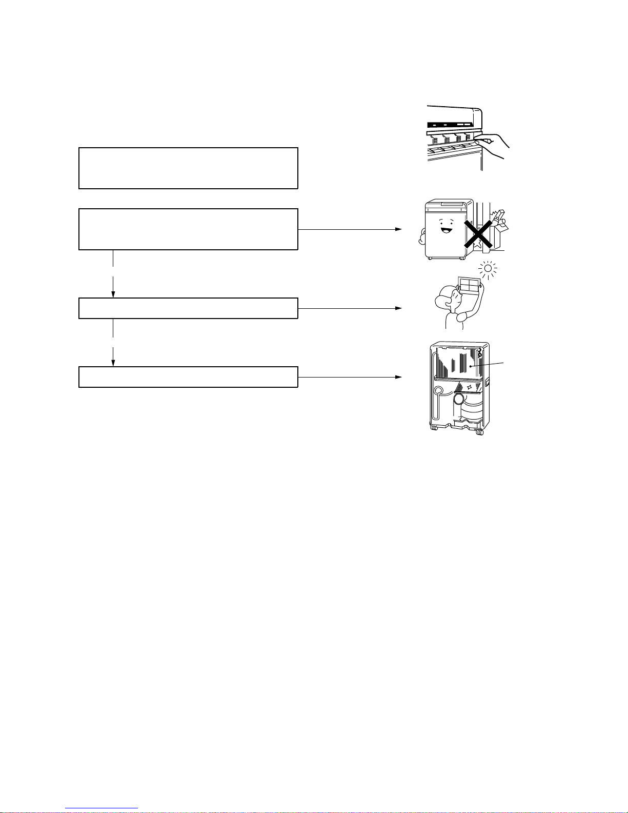
12-2.Routine Maintenance
(1) Be sure to observe the following for a longer ser-
vice life of your air conditioner.
• Cleaning of air filter: Once every two weeks
• Changing of water in tank: Once ever week
(2) Be sure to drain out the water in tank during ev-
ery off season.
12-3. Water Supply
(1) The water in tank decreases gradually in the
course of cooling operation.
(2) If the water is run out, the warning lamp lights up
(in red) and the operation mode is switched to
blowing. Then, refill the water.
(3) Open the front door, being down the tank tow ard
you, and lift off the tank.
Fig. 12-2
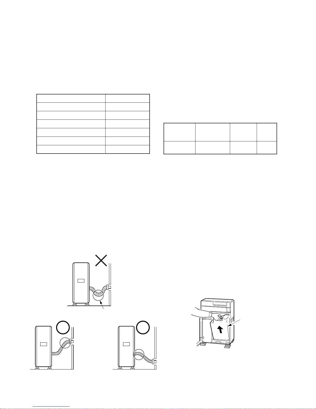
12. INSTALLATION INSTRUCTION
Read the installation manual carefully before installing the air conditioner.
The following items in table 12-1 are included as the
accessories.
4) If the exhaust hose is set with its tip down,
the water condensed within the hose might
leak out of the room. It is therefore recommended to set the hose with its tip kept higher
than the air outlet of the air conditioner properly.
(2) Put a seat under each caster.
(3) Electrical wiring.
Table 12-2
12-1.Installation Method
(1) Insert the connection port (round) into the air con-
ditioner surely to its root.
1) The exhaust hose may be extended or contracted from approx. 500 mm to approx. 1,400
mm, but use it in its shortest length if possible.
2) Be careful that a U-shaped bend or slack is
not yielded in the way of exhaust hose.
3) When you move the air conditioner, be sure
to pull out the exhaust hose and don’t lay down
the air conditioner.
Fig. 12-1
Q’ty
1
1
3
1
4
3
Parts name
Owner’s manual
Installation manual
Exhaust hole
Exhaust hose
Caster seat
Cap (for exhaust hole)
Table 12-1
Model
RAC-08EW-E
Fuse
rating
7A
Power
source
1φ 50 Hz,
220/230/240V
Plug
socket
rating
7A
Water stays
here.
Tank

– 25 –
12-4. Changing of Water
(1) As the water in tank becomes dirty gradually in
cooling water, change the w ater once ev ery week.
Fig. 12-3
(2) The water in tank becomes 50° or so in cooling
operation. It is abnormal at all.
12-5.Relocation of Air Conditioner
(1) When you move the air conditioner, be sure to
drain out the water in tank first, and do not lay
down the air conditioner.
Drain hose
– 26 –
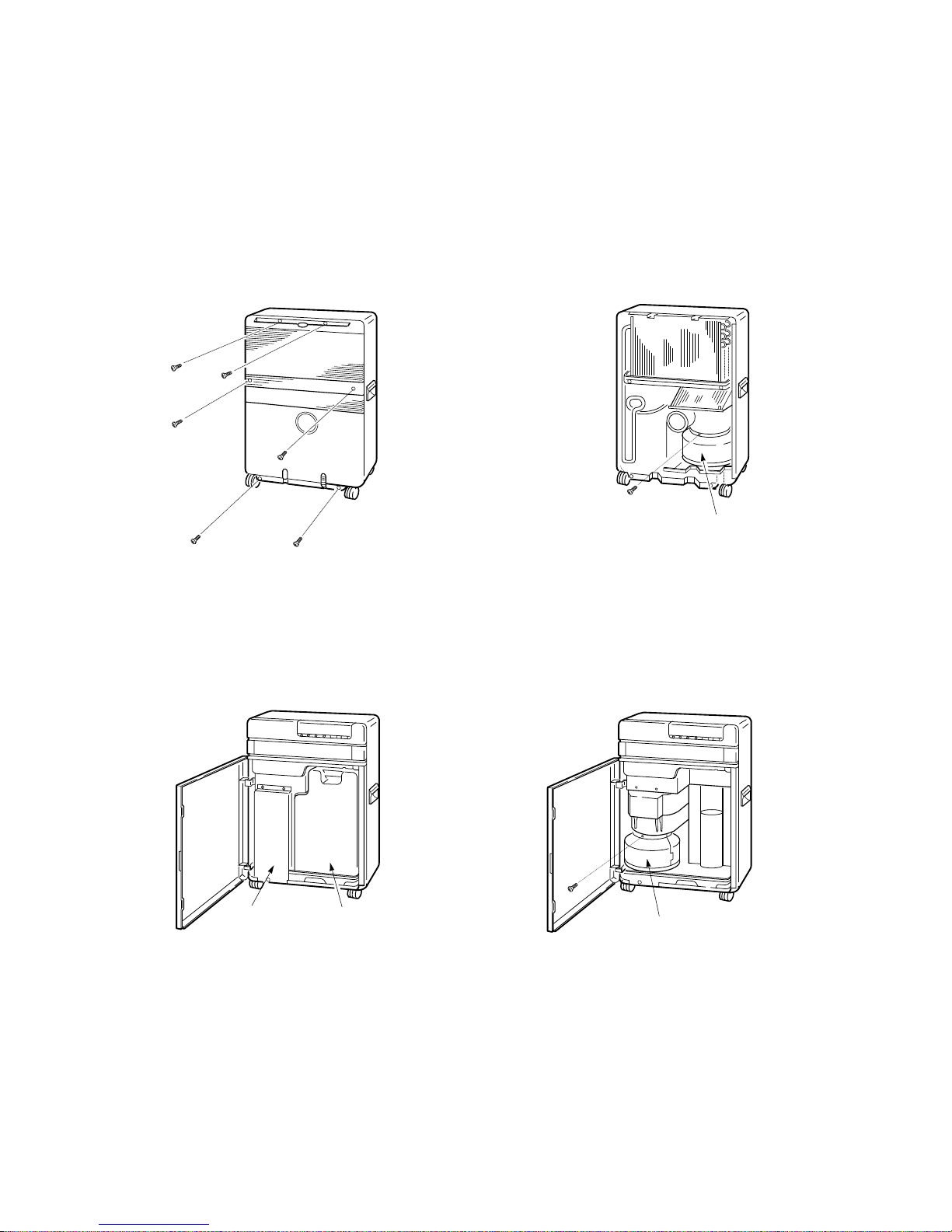
13. CLEANING METHOD OF CONDENSER
13-1. Condenser Servicing Procedures
(1) Pull out the air filter.
(2) Remove six screws at the back and take off the
rear panel. Also, pull out the drain hose from
case of hose.
Fig. 13-1
(3) Open the front door and remove the tank.
(4) Remove the inner cover (screwed down at five
spots).
Fig. 13-2
(5) Remove two screws fastening the condenser
cover (one in the front part and another in the
rear).
Fig. 13-3
(6) Remove the condenser cover by pulling it ob-
liquely upward, then the condenser will be exposed.
(7) When assembling, follow the reverse procedures.
Fig. 13-4
Inner cover Tank
Condenser cover
Condenser cover

– 27 –
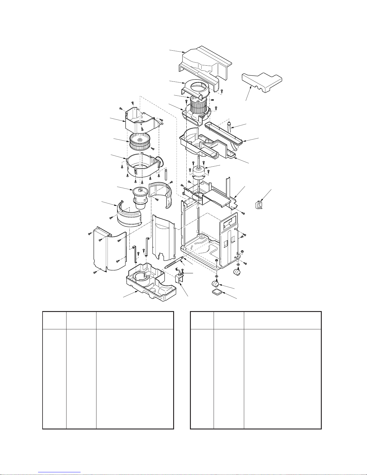
14. EXPLODED VIEWS AND PARTS LIST
201
242
251
208
202
206
205
203
236
210
212
211
207
209
238
237
246
204
253
255
256
"Special tool"
212 43079081 C ap, Water-Tank
236 43089126 Exhaust-Hose
237 43089127 Cap, Exhaust Hole
238 43089128 Exhaust Hole
242 43088645 Owner’s Manual
246 43069760 Cord Band
251 43068437 Control Panel
253 43009439 H-Louver
255 43097200 Tamper-Proof-Screw
256 43082263 Screw Driver
(Tamper-Proof-Screw)
Location Part
Description
No. No.
Location Part
Description
No. No.
201 43000679 Front Panel
202 43008399 Door, Control-Panel
203 43003190 Cabinet, Back
204 43000680 Cabinet
205 43080332 Air-Filter
206 43019800 Handle
207 43000678 Door, Front
208 43007917 Magnet Catch
209 43007916 Cover, Hinge
210 43079225 Tank, Water
211 43079226 Cap, Water-Tank

– 28 –
402
4
06
405
404
403
401
401 43058255 Transformer, FT67-2
402 43055420 Capacitor, Electrolytic
403 43060064 Cord, Power
404 43050341 Thermo-Sensor
405 43050340 Sensor, Heat Exchanger
406 43068439 PC Board Assembly
407 43031090 Diode-Block
408 43034070 Relay-Miniature, JE-X
409 43033197 Capacitor, Electrolytic
Location Part
Description
No. No.
Location Part
Description
No. No.
410 43055359 Toshiba Nonlinear Resistor
41 1 43035573 Surge Absorber
412 43031043 TR, 2SD880Y
413 43034036 Relay, Power
414 43060899 Fuse
415 43055462 Capacitor, EEP Series
416 43055284 Toshiba Nonlinear Resistor
417 43055508 Capacitor, CK

– 29 –
Location Part
Description
No. No.
Location Part
Description
No. No.
401 43058255 Transformer, FT67-2
402 43055420 Capacitor, Electrolytic
403 43060064 Cord, Power
404 43050341 Thermo-Sensor
405 43050340 Sensor, Heat Exchanger
406 43068439 PC Board Assembly
407 43031090 Diode-Block
408 43034070 Relay-Miniature, JE-X
409 43033197 Capacitor, Electrolytic
410 43055359 Toshiba Nonlinear Resistor
41 1 43035573 Surge Absorber
412 43031043 TR, 2SD880Y
413 43034036 Relay, Power
414 43060899 Fuse
415 43055462 Capacitor EEP Series
P06
CN03
RY01
R08
R09
CN02
CN04(WHI)
C50
P05
6.3A 250V~
CR01
D06
R73
Q02
C31 C30
R62
R74
R76
R76
R05
J02
C01
D05
RY03
RY02
F01
CN08
CR02
C35
P12
(RED)
J01
P10
R26
SG01
CR03
CN07
C
Q01
C06
C05
Q04
Q05
Q06
R10
C08
TC
R69
R70
R71
R22
R21
R20
R61
R63
IC01
C22
R60
R59
R58
R57
R92
R93
R94
R95
C32
C29
R72
R02
R01
C03
D02
C04
R64
D01
C02
C26
C28
C23
R65
R80
R81
R82
R83
R84
R85
R66
R67
R68
C36
C35
Q02
D04
E
B
R25
RY07
DB01
CN01
46
35
P11
(BLK)
1
3
E
E
E
C
C
C
B
B
B
C
E
B
21
TA
ECB
12
1 CN06 15
CN05(RED)
1
2
21
15
10
7
22 25 30 35
42
D03
C27
D20
C20
C07
R50
Q07
D07
R11
R03
R04
C21
R52
X01
C24
R90
C34
R51
C25
+5V
+5V
GND
E
C
B
ECB
Q03
MCC 702
04
COMPONENT SIDE
R
GCMK C1X
408
415
412
414
411
413 407 409
– 30 –
247
250
215
213
217
216
220
221
219
222
223
224
228
226
229
227
230
214
218
235
Drain hose
225
254
225 43051323 Switch, Float
226 43070139 Hose, Water
227 43019829 Caster
228 43079087 Cap
229 43063164 Cover, Switch
230 43089106 Seat-Caster
235 43011508 Cushion, Sub
247 43069761 Wire-Saddle
250 43021870 Motor, AC, 230V, 50Hz,
Fan STF-230-20-4C
254 43039306 Plate, Blower
Location Part
Description
No. No.
Location Part
Description
No. No.
213 43022394 Casing, Up
214 43022395 Casing, Low
215 43022396 Case, Fan, Up
216 43022397 Case, Fan, Low
217 43020249 Fan, Multi-Blade
218 43072327 Drain-Pan
219 43022392 Case, Fan, Exhaust
220 43022393 Cover, Fan, Exhaust
221 43020250 Fan, Multi-Blade
222 43020251 Fan, Water
223 43049666 Cover, Condenser
224 43072326 Water-Vessel

– 31 –
239 43095302 Cushion, Rubber
248 43007890 Holder, Sensor, TA
249 43063188 Holder-Sensor-TC
Location Part
Description
No. No.
Location Part
Description
No. No.
231 43041589 Compressor, PH94X1-4G1
232 43044543 Evaporator
233 43043523 Condenser
234 43043524 Condenser, Air
239
231 249
233
234
232
248

– 32 –

TOSHIBA CORPORATION
1–1, SHIBAURA 1– CHOME, MINATO – KU, TOKYO 105 – 01, JAPA N
 Loading...