

Page 1
FILE NO. A03-006
SERVICE MANUAL
<OWNERS MANUAL/INSTALLATION MANUAL>
SPLIT TYPE
RAV-SM561BT-E/RAV-SM560AT-E
RAV-SM801BT-E/RAV-SM800AT-E
RAV-SM1101BT-E/RAV-SM1100AT-E
RAV-SM1401BT-E/RAV-SM1400AT-E
R410A
PRINTED IN JAPAN, Feb., 2004 ToMo
Page 2

ADOPTION OF NEW REFRIGERANT
This Air Conditioner is a new type which adopts a new refrigerant HFC (R410A) instead of the conventional
refrigerant R22 in order to prevent destruction of the ozone layer.
RAV-SM560AT-E
RAV-SM800AT-E
WARNING
Cleaning of the air filter and other parts of the air filter involves dangerous work in high places, so be sure to
have a service person do it. Do not attempt it yourself . The cleaning diagram for the air filter is there for the
service person, and not for the customer.
RAV-SM1100AT-E
RAV-SM1400AT-E
RAV-SM561BT-E/RAV-SM801BT-E
RAV-SM1101BT-E/RAV-SM1401BT-E
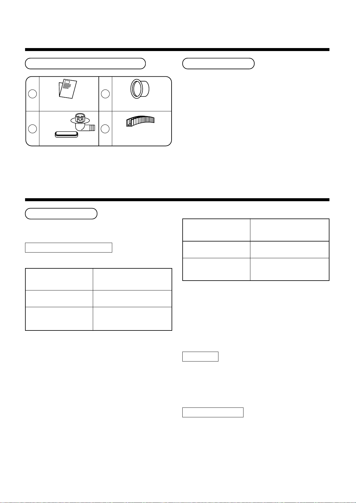
ACCESSORIES
Page 3

Outdoor Unit ––––––––––––––––––––––––––––––––––––––––––––––––––––––––
INSTALLATION MANU AL RAV-SM560AT-E/RA V-SM800AT-E
1
PRECAUTIONS FOR SAFETY.................................... 4
2
ACCESSORY AND REFRIGERANT ........................... 6
3
SELECTION OF INSTALLATION ................................ 6
4
REFRIGERANT PIPING ............................................ 11
5
EVACUATING............................................................. 13
6
ELECTRICAL WORK................................................. 15
7
FINAL INSTALLATION CHECKS.............................. 16
Outdoor Unit ––––––––––––––––––––––––––––––––––––––––––––––––––––––––
INSTALLATION MANU AL RAV-SM1100AT-E/RAV-SM1400AT-E
5
1
PRECAUTIONS FOR SAFETY.................................. 18
2
ACCESSORY AND REFRIGERANT ......................... 20
3
SELECTION OF INSTALLATION .............................. 20
4
REFRIGERANT PIPING ............................................ 24
EVACUATING............................................................. 26
6
ELECTRICAL WORK................................................. 28
7
FINAL INSTALLATION CHECKS.............................. 29
Indoor Unit –––––––––––––––––––––––––––––––––––––––––––––––––––––
RAV-SM561BT-E/RAV-SM801BT-E/RAV-SM1101BT-E/RAV-SM1401BT-E
Concealed Duct Type OWNER’S NANUAL
ACCESSORIES (SOLD SEPARATELY) ........................................ 31
PRECAUTIONS FOR SAFETY......................................................31
PARTS NAME ................................................................................33
PARTS NAME OF REMOTE CONTROLLER................................34
CORRECT USAGE ........................................................................37
AUTOMATIC OPERATION (Auto Changeover) ...........................37
TIMER OPERATION ......................................................................38
MAINTENANCE .............................................................................40
AIR CONDITIONER OPERATIONS AND PERFORMANCE ........41
RE-INSTALLATION........................................................................42
TROUBLES AND CAUSES ...........................................................42
TROUBLES AND CAUSES (Concerning Remote Controller)...44
RAV-SM560AT-E
RAV-SM800AT-E
RAV-SM1100AT-E
RAV-SM1400AT-E
Concealed Duct Type INSTALLATION MANUAL
Accessory parts and Parts to be procured locally ...... 45
1
PRECAUTIONS FOR SAFETY.................................. 46
2
SELECTION OF INSTALLATION PLACE ................. 48
3
INSTALLATION OF INDOOR UNIT........................... 49
4
AIR DUCTING WORK ................................................ 53
5
DRAIN PIPING WORK ............................................... 58
6
REFRIGERANT PIPING ............................................ 60
7
EVACUATING............................................................. 61
8
ELECTRICAL WORK................................................. 63
9
TEST RUN ................................................................. 65
10
TROUBLESHOOTING........................................... 66
11
Applicable Controls ............................................. 67
12
INST ALLATION/SER VICING TOOLS.................... 70
13
MAINTENANCE .................................................... 70
Accessories ––––––––––––––––––––––––––––––––––––––––––––––––––––
O WNER’S MANUAL
WEEKLY TIMER FOR AIR CONDITIONER (SPLIT TYPE)
<Program Weekly Timer T ype> RBC-EXW21E .......................................................................................................... 72
REMOTE CONTROLLER FOR AIR CONDITIONER
<Simple Operation Type> RBC-AS21E ............................................................................................................. 78
INSTALLATION MANU AL
Standard Remote Controller RBC-AMT21E........................................................................................................... 81
Simple Remote Controller RBC-AS21E ............................................................................................................. 82
Program Weekly Timer RBC-EXW21E .......................................................................................................... 83
Remote sensor TCB-TC21LE............................................................................................................ 84
Zeolite-3G Deodorant Filter TCB-FPC11BE/TCB-FPC21BE/TCB-FPC31BE/TCB-FPC41BE ........................... 85
High-Efficiency Filter .................................................................................................................................. 86
High-Efficiency filter (65%) TCB-UFM11BE/TCB-UFM21BE/TCB-UFM31BE/TCB-UFM41BE
High-Efficiency filter (90%) TCB-UFH51BE/TCB-UFH61BE/TCB-UFH71BE/TCB-UFH81BE
Deodorant Filter, Ammonium Filter .................................................................................................................................. 87
Deodorant Filter TCB-DF11BE/TCB-DF21BE/TCB-DF31BE/TCB-DF41BE
Ammonium Filter TCB-DF11BE-AM/TCB-DF21BE-AM/TCB-DF31BE-AM/TCB-DF41BE-AM
RAV-SM561BT-E/RAV-SM801BT-E
RAV-SM1101BT-E/RAV-SM1401BT-E
ACCESSORIES
Page 4
1
• Ensure that all Local, National and International regulations are satisfied.
• Read this “PRECAUTIONS FOR SAFETY” carefully before Installation.
• The precautions described below include the important items regarding safety. Observe them without fail.
RAV-SM560AT-E
RAV-SM800AT-E
• After the installation work, perform a trial operation to check for any prob lem.
Follow the Owner’s Manual to explain how to use and maintain the unit to the customer.
• Turn off the main power supply switch (or breaker) before the unit maintenance.
• Ask the customer to keep the Installation Manual together with the Owner’s Manual.
PRECAUTIONS FOR SAFETY
CAUTION New Refrigerant Air Conditioner Installation
• THIS AIR CONDITIONER ADOPTS THE NEW HFC REFRIGERANT (R410A) WHICH DOES NOT DE-
STROY OZONE LAYER.
The characteristics of R410A refrigerant are ; easy to absorb water, oxidizing membrane or oil, and its pressure
is approx. 1.6 times higher than that of refrigerant R22. Accompanied with the new refrigerant, refrigerating oil
has also been changed. Therefore, during installation work, be sure that water , dust, former refrigerant, or
refrigerating oil does not enter the refrigerating cycle.
To prevent charging an incorrect refrigerant and refrigerating oil, the sizes of connecting sections of charging
port of the main unit and installation tools are charged from those for the conventional refrigerant.
Accordingly the exclusive tools are required for the new refrigerant (R410A).
For connecting pipes, use new and clean piping designed for R410A, and please care so that water or dust
does not enter. Moreover, do not use the existing piping because there are problems with pressure-resistance
force and impurity in it.
CAUTION To Disconnect the Appliance from Main Power Supply.
This appliance must be connected to the main power supply by means of a switch with a contact separation of
at least 3 mm.
The installation fuse (25A D type ) must be used for the power supply line of this conditioner.
WARNING
• Ask an authorized dealer or qualified installation professional to install/maintain the air
conditioner.
Inappropriate installation may result in water leakage, electric shock or fire.
• Turn off the main power supply switch or breaker before attempting any electrical work.
Make sure all power switches are off. Failure to do so may cause electric shock.
• Connect the connecting cable correctly.
If the connecting cable is connected in a wrong way, electric parts may be damaged.
• When moving the air conditioner for the installation into another place, be very careful not
to enter any gaseous matter other than the specified refrigerant into the refrigeration cycle.
If air or any other gas is mixed in the refrigerant, the gas pressure in the refrigeration cycle becomes abnormally high and it may resultingly causes pipe burst and injuries on persons.
• Do not modify this unit by removing any of the safety guards or by by-passing any of the
safety interlock switches.
• Exposure of unit to water or other moisture before installation may cause short-circuit of
electrical parts.
Do not store it in a wet basement or expose to rain or water.
4
Page 5
• After unpacking the unit, examine it carefully if there are possible damage.
• Do not install in a place that might increase the vibration of the unit.
• To avoid personal injury (with sharp edges), be careful when handling parts.
• Perform installation work properly according to the Installation Manual.
Inappropriate installation may result in water leakage, electric shock or fire.
• When the air conditioner is installed in a small room, provide appropriate measures to
ensure that the concentration of refrigerant leakage occur in the room does not exceed the
critical level.
• Install the air conditioner securely in a location where the base can sustain the weight
adequately.
• Perform the specified installation work to guard against an earthquake .
If the air conditioner is not installed appropriately, accidents may occur due to the falling unit.
• If refrigerant gas has leaked during the installation work, ventilate the room immediately.
If the leaked refrigerant gas comes in contact with fire, noxious gas may generate.
• After the installation work, confirm that refrigerant gas does not leak.
If refrigerant gas leaks into the room and flows near a fire source, such as a cooking range, noxious gas
might generate.
• Electrical work must be performed by a qualified electrician in accordance with the Installa-
tion Manual. Make sure the air conditioner uses an exclusive power supply.
An insufficient power supply capacity or inappropriate installation may cause fire.
RAV-SM560AT-E
RAV-SM800AT-E
• Use the specified cables for wiring connect the terminals securely fix. To prevent external
forces applied to the terminals from affecting the terminals.
• Be sure to provide grounding.
Do not connect ground wires to gas pipes, water pipes, lightning rods or g round wires for telephone cables.
• Conform to the regulations of the local electric company when wiring the power supply.
Inappropriate grounding may cause electric shock.
• Do not install the air conditioner in a location subject to a risk of exposure to a combustible
gas.
If a combustible gas leaks, and stays around the unit, a fire may occur.
Required tools for installation work
1) Philips screwdriver
2) Hole core drill (65 mm)
3) Spanner
4) Pipe cutter
5) Knife
6) Reamer
7) Gas leak detector
8) Tape measure
9) Thermometer
10) Mega-tester
11) Electro circuit tester
12) Hexagonal wrench
13) Flare tool
14) Pipe bender
15) Level vial
16) Metal saw
R410A (Special requirement)
17) Gauge manifold
(Charge hose : R410A special requirement)
18) Vacuum pump
(Charge hose : R410A special requirement)
19) Torque wrench
1/4 (17 mm) 16 N•m (1.6 kgf•m)
3/8 (22 mm) 42 N•m (4.2 kgf•m)
1/2 (26 mm) 55 N•m (5.5 kgf•m)
5/8 (15.9 mm) 120 N•m (12.0 kgf•m)
20) Copper pipe gauge adjusting projection margin
21) Vacuum pump adapter
5
Page 6
2
ACCESSORY AND REFRIGERANT
Accessory and Installation Parts Refrigerant Piping
• Piping kit used for the conventional refrigerant cannot
be used.
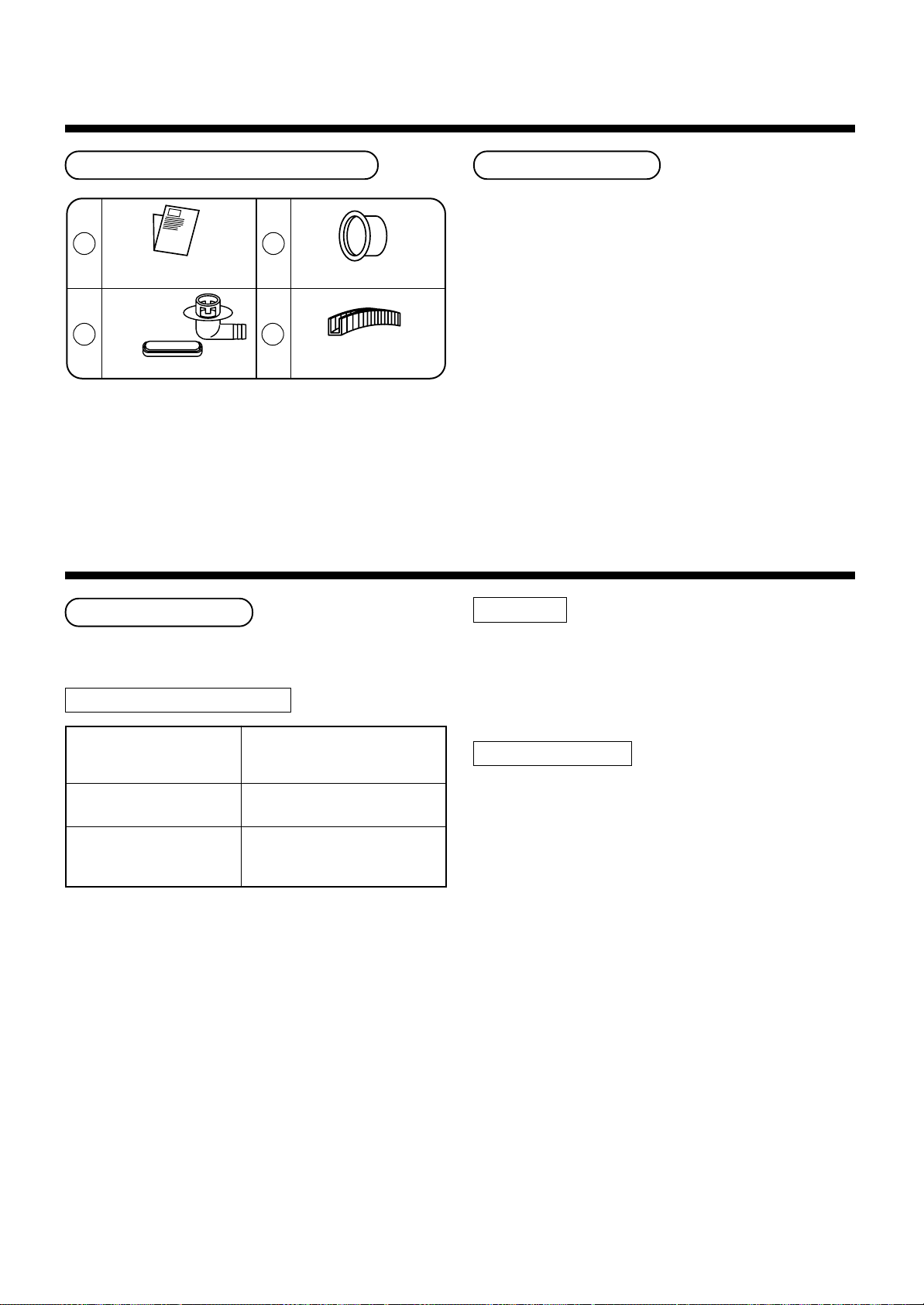
1
Outdoor unit
Installation manual x 1
Drain nipple
2
Waterproof rubber cap
3
Protective bush
(For SM800AT only)
4
Guard material for
passage part
(For SM800AT only)
• Use copper pipe with 0.8 mm or more thickness for
Ø6.4, Ø9.5, Ø12.7.
Use copper pipe with 1.0 mm or more thickness for
Ø15.9.
• Flare nut and flare works are also different from those
of the conventional refrigerant. Take out the flare nut
attached to the main unit of the air conditioner, and
use it.
3
SELECTION OF INSTALLATION
Before installation
Be careful to the following items before installation.
Length of refrigerant pipe
<SM560AT-E>
Length of refrigerant pipe
connected to
indoor/outdoor unit
20m or shorter
21m to 30m
*
* Caution at addition of refrigerant
When the total length of refrigerant pipe exceeds
20m, add 20g/m of refrigerant and the maximum total
length of pipe is 30m.
(Max. amount of additional refrigerant is 200g.)
Charge the refrigerant accurately. Overcharge may
cause a serious trouble of compressor .
Addition of refrigerant is
unnecessary at the local site.
<Addition of refrigerant>
Add 20g of refrigerant for every
1m of pipe which exceeds 20m.
Item
<SM800AT-E>
Length of refrigerant pipe
connected to
indoor/outdoor unit
20m or shorter
21m to 50m
*
* Caution at addition of refrigerant
When the total length of refrigerant pipe exceeds
20m, add 40g/m of refrigerant and the maximum total
length of pipe is 50m.
(Max. amount of additional refrigerant is 1200g.)
Charge the refrigerant accurately. Overcharge may
cause a serious trouble of compressor .
Addition of refrigerant is
unnecessary at the local site.
<Addition of refrigerant>
Add 40g of refrigerant for every
1m of pipe which exceeds 20m.
Item
Air purge
• For air purge, use a vacuum pump.
• Do not use refrigerant charged in the outdoor unit for
air purge. (The refrigerant for air purge is not contained in the outdoor unit.)
Electrical cabling
• Be sure to fix the power cables and indoor/outdoor
connecting cables with clamps so that they do not
contact with the cabinet, etc.
6
Page 7
500
or more
150
or more
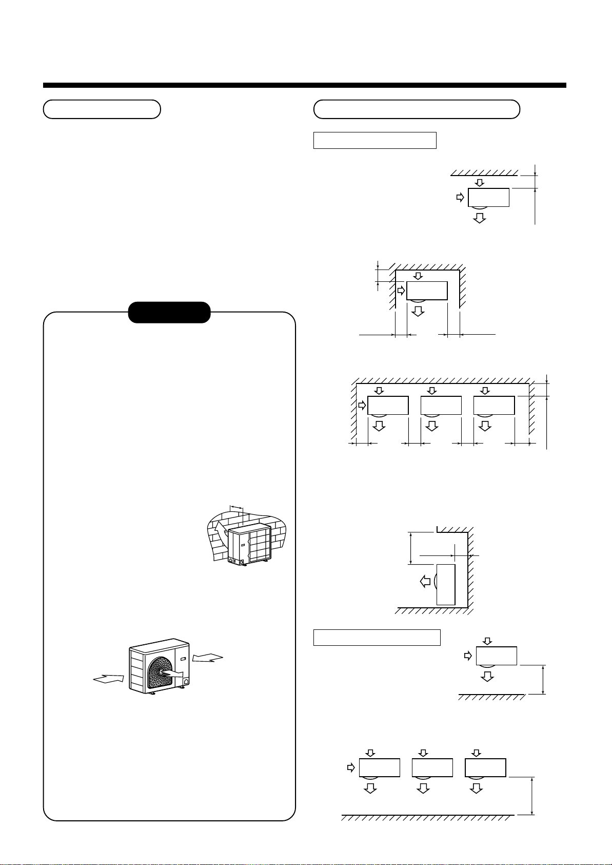
Installation Place
Necessary Space for Installation
• A place which provides a specified space around the
outdoor unit.
• A place where the operation noise and discharged air
are not given to your neighbors .
• A place that is not exposed to a strong wind.
• A place that does not block a passage.
• When the outdoor unit is installed in an elev ated
position, be sure to secure its feet.
• There must be sufficient space for carrying in the
unit.
• A place where the drain water does not make an y
problem.
CAUTION
1. Install the outdoor unit at a place where dis-
charge air is not blocked.
2. When an outdoor unit is installed in a place that
is always exposed to a strong wind like a coast
or on a high story of a building, secure a normal
fan operation b y using a duct or a wind shield.
3. When installing the outdoor unit in a place that is
constantly exposed to a strong wind such as the
upper stairs or rooftop of a building, apply the
windproof measures referring to the follo wing
examples.
1) Install the unit so that its
discharge port faces to the
wall of the building. Keep a
distance 500 mm or more
between the unit and the
wall surface .
500
Obstacle at rear side
<Upper side is free>
1. Single unit installation
2. Obstacles at both right and left sides.
200
or more
150
or more
The height of the
obstacle should be
lower than the height
of the outdoor unit.
300
or more
3. Serial installation of two or more units
150
or more
The height of the obstacle should be lower
than the height of the outdoor unit.
300
or more
300
or more
<Obstacle also at the upper side>
150
300
or more
or more
200 or more
2) Supposing the wind direction during the
operation season of the air conditioner, install
the unit so that the discharge port is set at
right angle to the wind direction.
Strong
wind
Strong
wind
4. Installation in the following places ma y result in
some troubles. Do not install the unit in such
places below.
• A place full of machine oil.
• A place full of sulfuric gas.
• A place where high-frequency radio waves are
likely to be generated as from audio equipment, welders, and medical equipment.
Obstacle at front side
<Upper side is free>
1. Single unit installation
2. Serial installation of two or more units
7
500
1000
or more
or more
Page 8
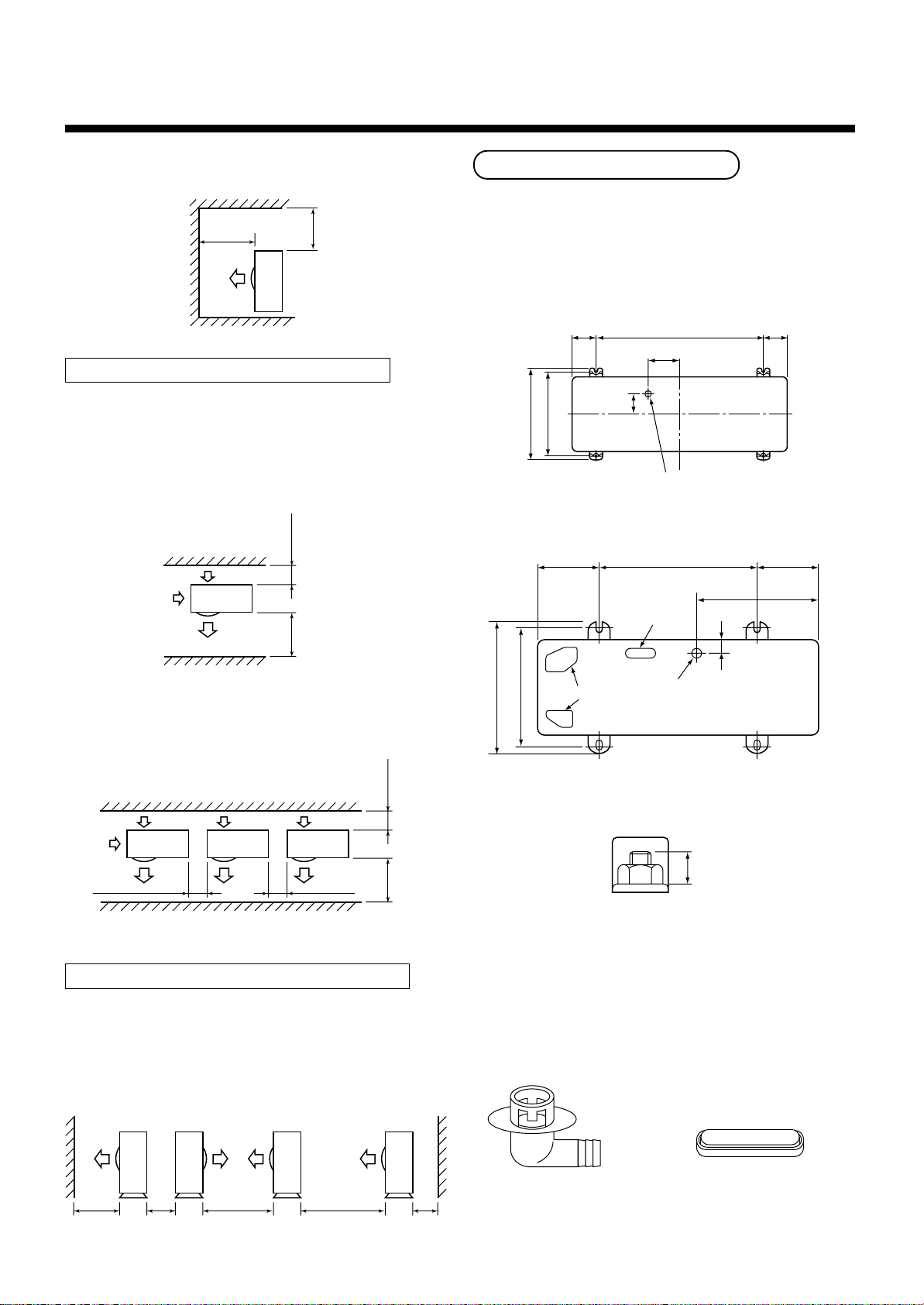
15 or less
3
SELECTION OF INSTALLATION
<Obstacle also at the upper side>
1000
or more
1000
or more
Obstacles at both front and rear sides
Open the upper side and both right and left sides.
The height of obstacle at both front and rear side,
should be lower than the height of the outdoor unit.
<Standard installation>
1. Single unit installation
150
or more
1000
or more
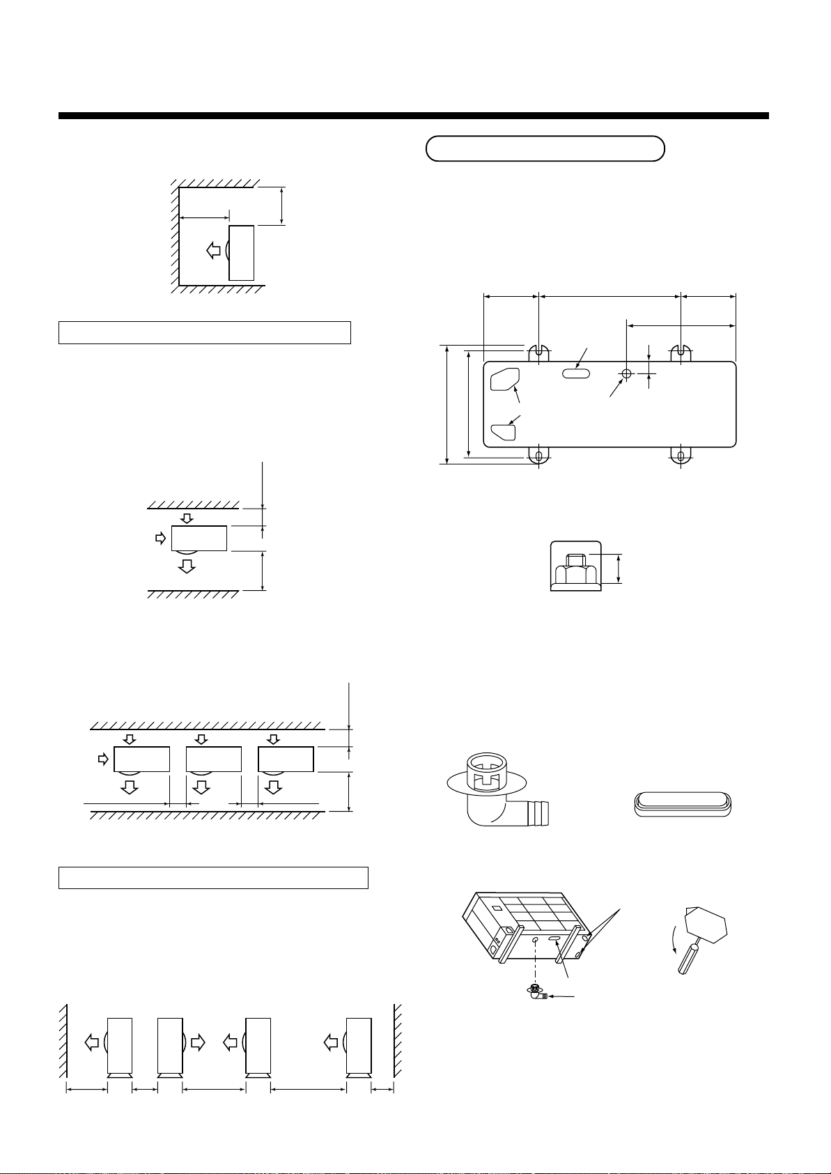
Installation of Outdoor Unit
• Before installation, check strength and horizontality of
the base so that abnormal sound does not generate.
• According to the following base diagram, fix the base
firmly with the anchor bolts.
(Anchor bolt, nut: M10 x 4 pairs)
<SM560AT-E>
600
115
76
Ø28 Drain hole
600150 150
430
Drain hole
40
310
330
<SM800AT-E>
90 90
2. Serial installation of two or more units
200
or more
300
or more
300
or more
1000
or more
Serial installation at front and rear sides
Open the upper side and both right and left sides.
The height of obstacle at both front and rear sides
should be lower than the height of the outdoor unit.
<Standard installation>
400
365
Knockout hole
Drain nipple mounting hole
Set the out margin of the anchor bolt to 15mm or less.
• In case of draining through the drain hose, attach the
following dr ain nipple and the waterproof rubber cap,
and use the drain hose (Inner diam.: 16mm) sold on
the market. And also seal the screws securely with
silicone material, etc. so that w ater does not drop
down. Some conditions may cause dewing or dripping of water.
1000
or more
300
or more
1500
or more
2000
or more
200
or more
Drain nipple Waterproof rubber cap
8
Page 9
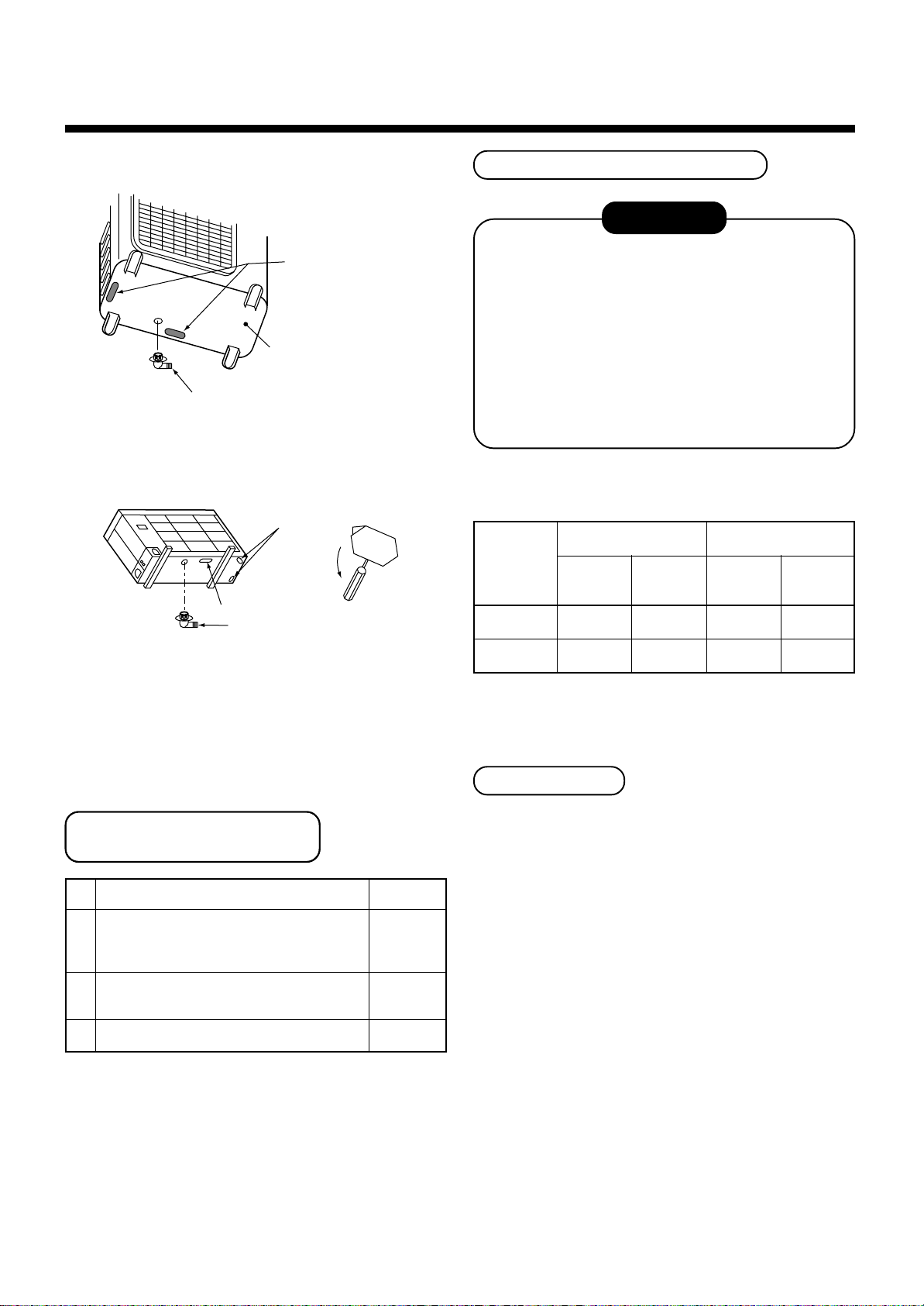
<SM560AT-E>
Refrigerant Piping Connection
CAUTION
Waterproof rubber cap
Base plate
Drain nipple
<SM800AT-E>
Knockout hole
Open
Waterproof rubber cap
Drain nipple
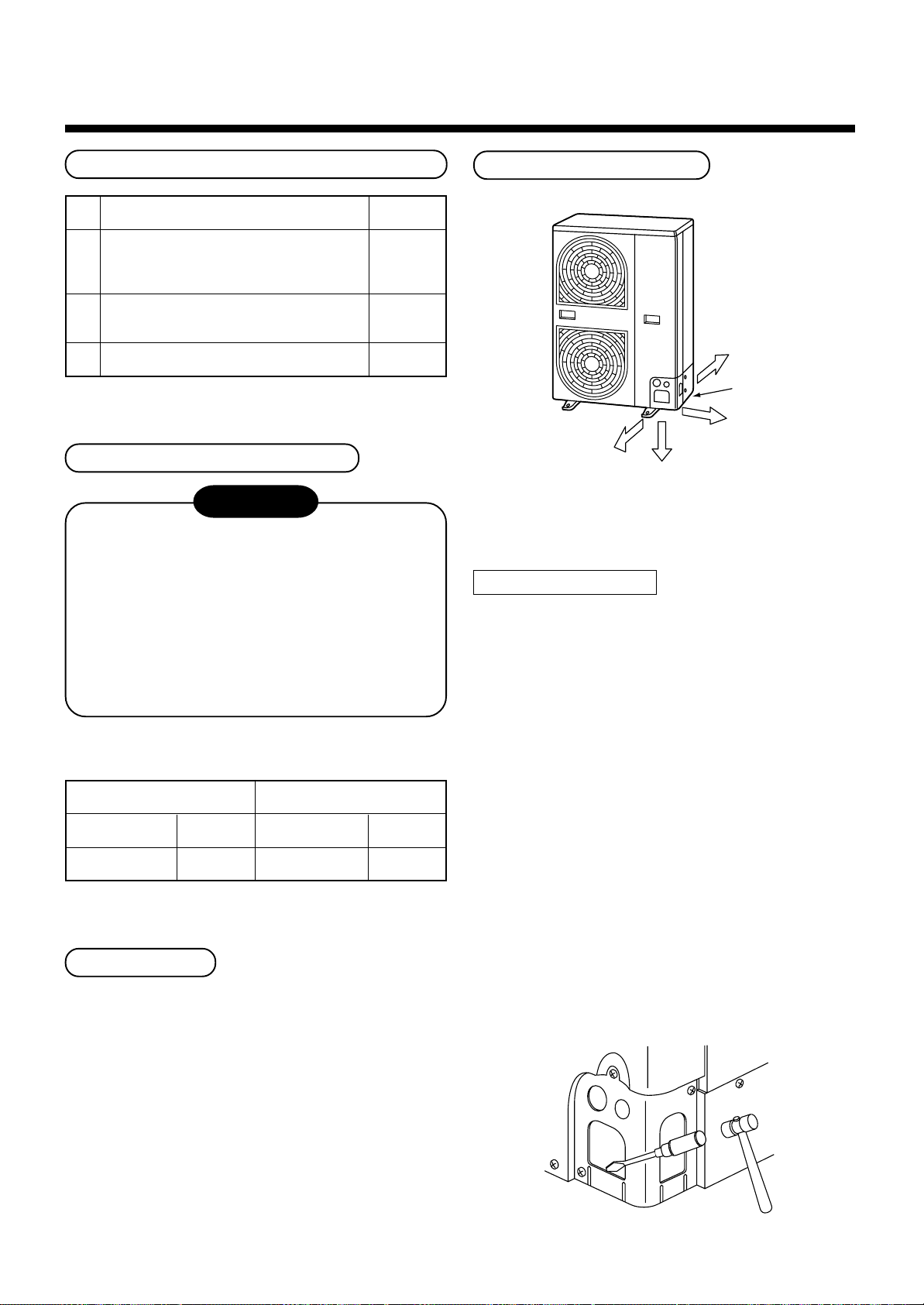
• When there is a possibility of freezing of drain at the
cold district or a snowfall area, be careful for drainage
ability of drain. The dr ainage ability increases when a
knockout hole on the base plate is opened. (Open the
knockout hole to outside using a screwdriver, etc.)
TAKE NOTICE THESE IMPORTANT
4 POINTS BELOW FOR PIPING WORK
1. Keep dust and moisture away from inside the
connecting pipes.
2. Tightly connect the connection between pipes
and the unit.
3. Evacuate the air in the connecting pipes using
VACUUM PUMP.
4. Check gas leak at connected points.
<Piping connection>
Capacity
rank
RAV-
SM560
SM800
Liquid side
Outer
diameter
Ø6.4 0.8
Ø9.5 0.8
Thickness
Gas side
Outer
diameter
Ø12.7 0.8
Ø15.9 1.0
Thickness
For Reference
Optional Installation Parts
(Local Procure)
Parts name
Refrigerant piping
A
Liquid side : Ø6.35 mm or Ø9.52 mm
Gas side : Ø12.7 mm or Ø15.9 mm
Pipe insulating material
B
(polyethylene foam, 6 mm thick)
C
Putty, PVC tapes
Q’ty
Each one
1
Each one
If a heating operation would be continuously performed
for a long time under the condition that the outdoor
temperature is 0°C or lower, draining of defrosted water
may be difficult due to freezing of the bottom plate,
resulting in a trouble of the cabinet or fan.
It is recommended to procure an anti-freeze heater
locally for a safety installation of the air conditioner.
For details, contact the dealer.
9
Page 10
3
SELECTION OF INSTALLATION
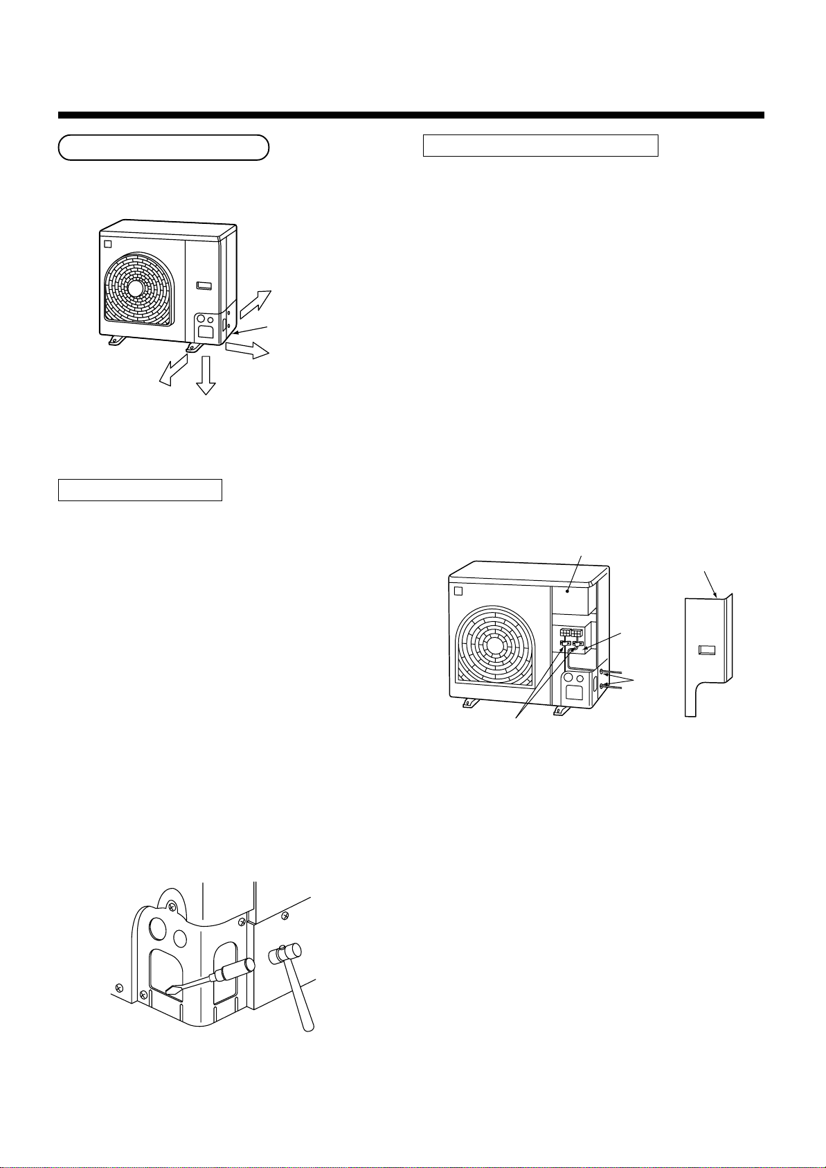
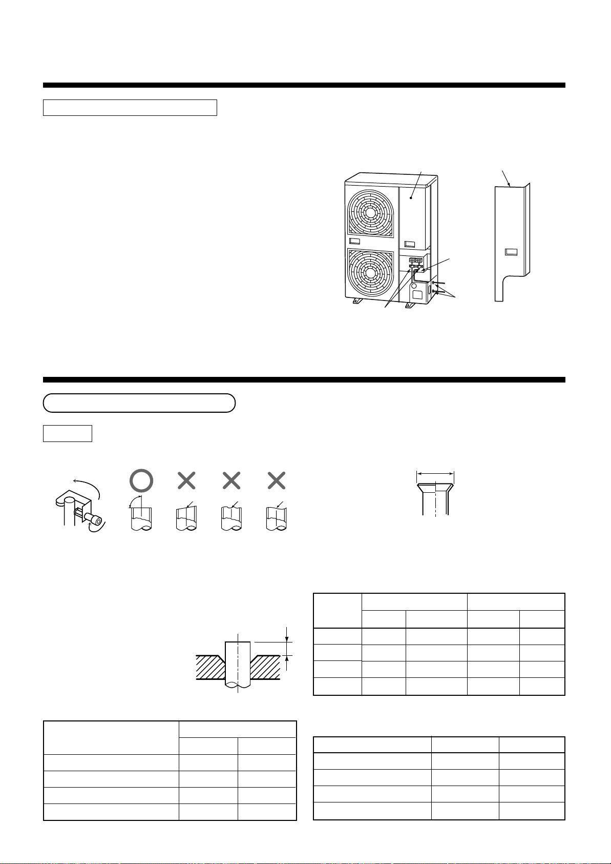
Knockout of Pipe Cover
<SM800AT-E>
Rear direction
Pipe cover
Side direction
Front direction
Down direction
Knockout procedure
• The indoor/outdoor connecting pipes can be connected to 4 directions.
Take off the knock out part of the pipe cover in which
pipes or wires pass through the base plate.
• As shown in the figure, do not remove the pipe cover
from the cabinet so that the knockout hole can be
easily punched. To knock out, it is easily taken off by
hands by punching a position at the lower side of 3
connected parts with screwdriver along the guideline.
• After marking the knockout hole, remove the burr and
mount the attached protective bush and guard
material for pass-through part in order to protect
pipes and wires.
How to remove the front panel
1. Remove scre ws of the front panel.
2. Pull the front panel downward.
Removing the front panel, the electric parts appear at
the front side.
• The metal pipes are attachable to the piping holes.
If the size of the used power pipe does not match
with the hole, adjust the hole size to match with pipe
size.
• Be sure to fix the power cable and indoor/outdoor
connecting cable with bundling band sold on the
market so that they do not mak e contact with the
compressor and discharge pipe.
(Temperature of the compressor and discharge pipe
becomes high.)
In order to avoid the force applied to on the connecting section, be sure to fix the cables to the cord
clamps provided on the pipe valve fixing plate and the
electric parts box.
Electric parts box
Front panel
Pipe valve
fixing plate
Piping
hole
Cord clamp
After connecting the pipes, be sure to mount the pipe
cover. The pipe cover is easily mounted by cutting off
the slit at the lower part of the pipe cover.
10
Page 11
4
REFRIGERANT PIPING
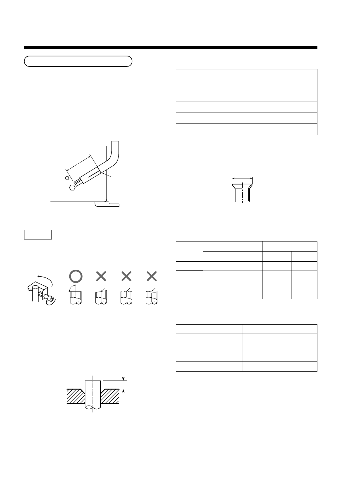
Pipe Forming/End Positioning
<SM560AT-E>
• Forming of pipe
Form the pipe along with a marked line of the cabinet.
• End positioning of pipe
Match the ends of both pipes at a distance of
85 mm apart from the marked line.
85mm
Marked line
Flaring
• Flaring siz e : A (Unit : mm)
+0
A
Outer diam. of copper pipe
6.35
9.52
12.7
15.9
R410A R22
9.1 9.0
13.2 13.0
16.6 16.2
19.7 19.4
- 0.4
* In case of flaring for R410A with the conventional
flare tool, pull it out approx. 0.5 mm more than that of
R22 to adjust to the specified flare size. The copper
pipe gauge is useful for adjusting projection margin
size.
A
• Projection margin in flaring : B (Unit : mm)
Rigid (Clutch type)
1. Cut the pipe with a pipe cutter.
90˚
Obliquity Roughness Warp
2. Insert a flare nut into the pipe, and flare the pipe.
As the flaring sizes of R410A differ from those of
refrigerant R22, the flare tools newly manufactured
for R410A are recommended.
However, the conventional tools can be used by
adjusting projection margin of the copper
pipe.
B
Outer diam.
of copper
pipe
6.35
9.52
12.7
15.9
R410A tool used
R410A R22
0 to 0.5
0 to 0.5
0 to 0.5
0 to 0.5
(Same as left)
(Same as left)
(Same as left)
(Same as left)
Imperial (Wing nut type)
Outer diam. of copper pipe
6.35
9.52
12.7
15.9
Conventional tool used
R410A R22
1.0 to 1.5 0.5 to 1.0
1.0 to 1.5 0.5 to 1.0
1.0 to 1.5 0.5 to 1.0
1.0 to 1.5 0.5 to 1.0
R410A R22
1.5 to 2.0 1.0 to 1.5
1.5 to 2.0 1.0 to 1.5
2.0 to 2.5 1.5 to 2.0
2.0 to 2.5 1.5 to 2.0
11
Page 12
4
REFRIGERANT PIPING
Tightening of Connecting Part
(Unit: N•m)
Outer diam. of copper pipe
6.35mm (diam.)
9.52mm (diam.)
12.7mm (diam.)
15.9mm (diam.)
Flare at
indoor unit side
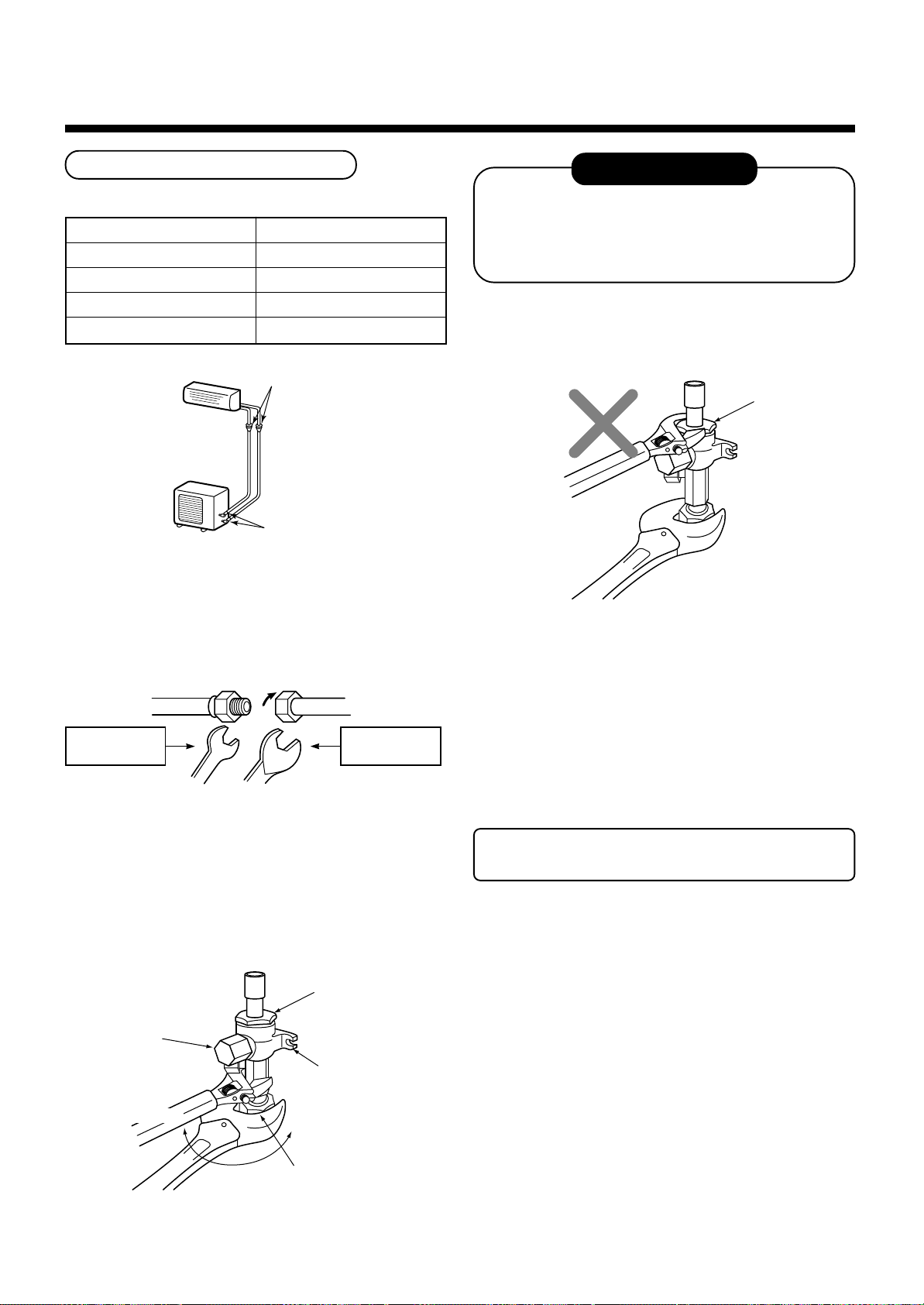
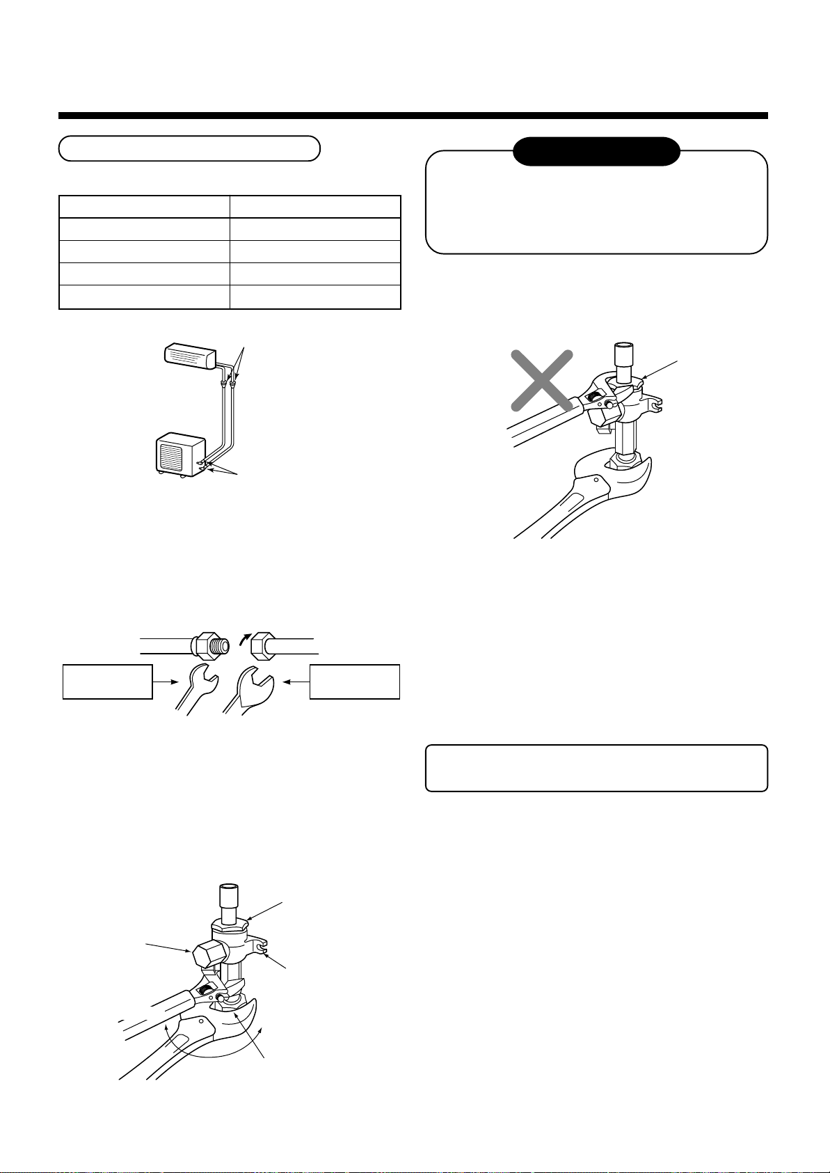
• Align the centers of the connecting pipes and tighten
the flare nut strong as far as possib le with your
fingers.
Then fix the nut with a spanner and tighten it with
torque wrench as shown in the figure.
Tightening torque
14 to 18 (1.4 to 1.8kgf•m)
33 to 42 (3.3 to 4.2kgf•m)
50 to 62 (5.0 to 6.2kgf•m)
68 to 82 (6.8 to 8.2kgf•m)
Flare at
outdoor unit side
REQUIREMENT
1. Do not put the spanner on the cap. The valve
may be broken.
2. If applying excessive torque, the nut may be
broken according to some installation conditions.
• After the installation work, be sure to check gas leak
of connecting part of the pipes with nitrogen.
Cover
Half union or packed valve Flare nut
Externally
threaded side
Fix with spanner.
Tighten with torque wrench.
Internally
threaded side
• As shown in the figure, be sure to use a double
spanner to loosen or tighten the flare nut of the valve
at gas side. If using a single spanner, the nut cannot
be tightened with necessary tightening torque.
On the contrary, use a single spanner to loosen or
tighten the flare nut of the valve at liquid side.
Cover
Cap
Piping valve
Loosened
Tightened
• Pressure of R410A is higher than that of R22
(Approx. 1.6 times). Therefore, using a torque
wrench, tighten the flare pipe connecting sections
which connect the indoor/outdoor units at the specified tightening torque. Incomplete connections may
cause not only a gas leak, but also a trouble of the
refrigeration cycle.
Do not apply refrigerating machine oil to
the flared surface.
Flare nut
SM800 type valve at gas side
12
Page 13
5
EVACUATING
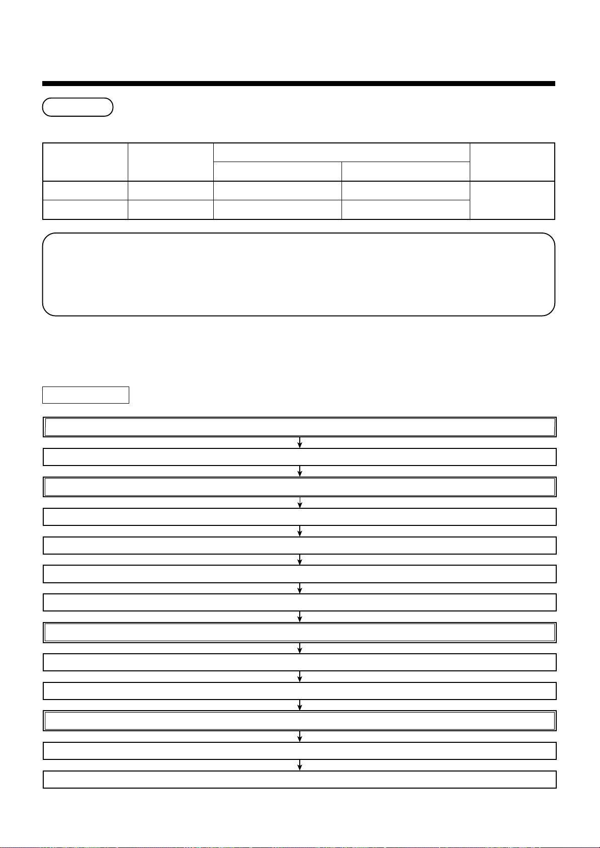
Air Purge
This air conditioner can be installed up to the connecting pipe length and height difference in the following table.
Capacity rank
SM560 type
SM800 type
With respect to the preservation of terrestrial environment, adopt “Vacuum pump” for air purge (Evacuate air in
the connecting pipes) when installing the unit.
• Do not discharge the refrigerant gas to the atmosphere to preserve the terrestrial environment.
• Use a vacuum pump to discharge the air (nitrogen, etc.) remained in the set. If the air remains, the capacity
may decrease.
For the vacuum pump, be sure to use one with backflow preventer so that the oil in the pump does not backflow
into the pipe of the air conditioner when the pump stops. (If oil in the vacuum pump is put in an air conditioner
including R410A, it may cause trouble on the refrigeration cycle .)
Max. connecting
pipe length (m)
30
50
Outdoor unit at upper side Outdoor unit at lower side
Height difference (m)
30 15
30 15
Hexagonal
wrench size
4mm
Vacuum pump
As shown in the right figure, connect the charge hose after the manifold valve are closed completely.
Attach the connecting port of the charge hose with a projection to push the valve core (setting pin) to the charge port of the set.
Open the handle Low fully.
Turn ON the vacuum pump (*1)
Loosen the flare nut of the packed valve (Gas side) a little to check the air passes through. (*2)
Tighten the flare nut again.
Execute vacuuming until the compound pressure gauge indicates –101kPa (–76cmHg). (*1)
Close handle Low completely.
Turn OFF the vacuum pump.
Leave the vacuum pump as it is for 1 or 2 minutes, and check the indicator of the compound pressure gauge does not return.
Open fully the valve stem or the valve handle. (First, at liquid side, then gas side)
Disconnect the charge hose from the charge port.
Tighten valve and caps of the charge port surely.
13
Page 14
5
EVACUATING
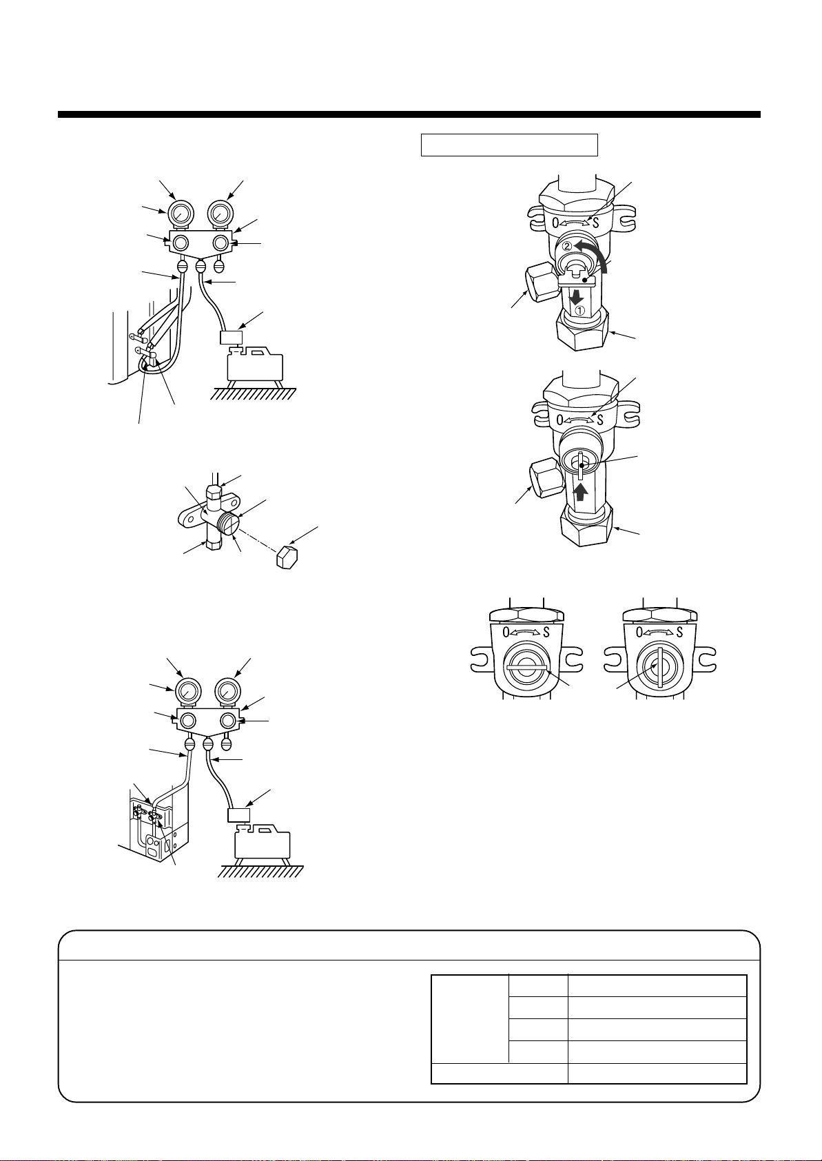
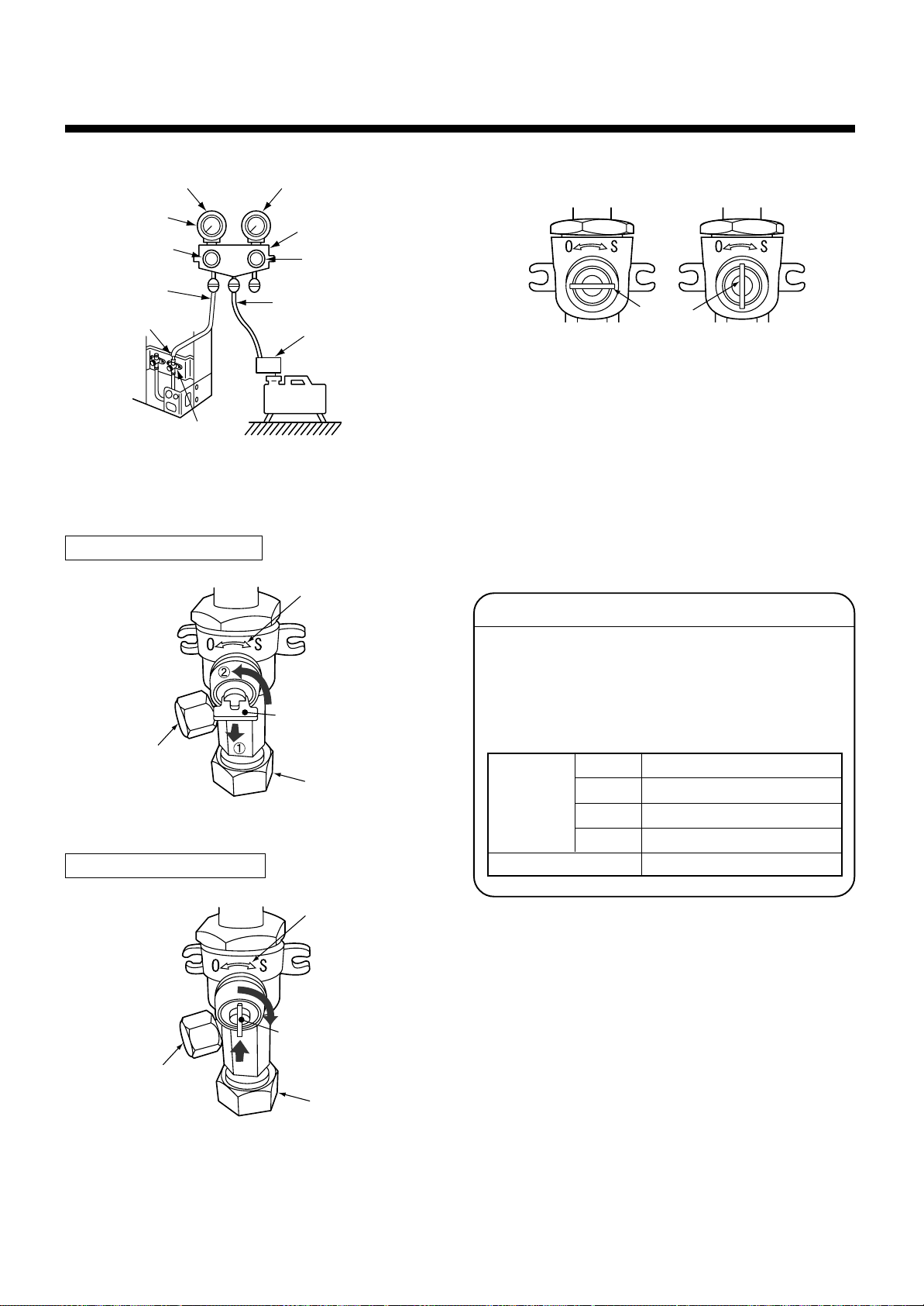
<SM560AT-E>
Compound pressure gauge
–101kPa
(–76cmHg)
Handle Lo
Charge hose
(For R410A only)
Packed valve (Gas side)
Service port (Valve core (Setting pin))
Valve unit
Charge port
Pressure gauge
Valve rod
Manifold valve
Handle Hi
(Keep fully closed)
Charge hose
(For R410A only)
Vacuum pump adapter
for counter-flow prevention
(For R410A only)
Vacuum
pump
Flare nut
Stopper
Charge cap
How to open the valve
Charge port
Charge port
Handle position
Valve unit
Handle
Pull out the handle and
using cutting pliers, etc.
turn it counterclockwise
by 90˚. (Open fully)
Flare nut
Valve unit
Push in handle.
Flare nut
<SM800AT-E>
Compound pressure gauge
–101kPa
(–76cmHg)
Handle Lo
Charge hose
(For R410A only)
Service port
(Valve core (Setting pin))
Packed valve at gas side
Pressure gauge
Manifold valve
Handle Hi
(Keep fully closed)
Charge hose
(For R410A only)
Vacuum pump adapter
for counter-flow prevention
(For R410A only)
Vacuum
pump
Valve handling precautions
• Open the valve stem or the handle until it strikes
the stopper. It is unnecessary to apply further
force.
• Securely tighten the cap with a torque wrench.
• Cap tightening torque
Handle
Closed completely
Opened fully
*1. Use the vacuum pump, vacuum pump adapters,
and gauge manifold referring to the manuals
attached to each tool before using them. For the
vacuum pump, check oil is filled up to the specified
line of the oil gauge.
*2. While the air is purged, check again that the
connecting port of charge hose, which has a
projection to push the valve core, is firmly connected to the charge port.
Valve size
Charge port
Ø6.4
Ø9.5
Ø12.7
Ø15.9
14 to 18N•m (1.4 to 1.8kgf•m)
33 to 42N•m (3.3 to 4.2kgf•m)
33 to 42N•m (3.3 to 4.2kgf•m)
20 to 25N•m (2.0 to 2.5kgf•m)
14 to 18N•m (1.4 to 1.8kgf•m)
14
Page 15
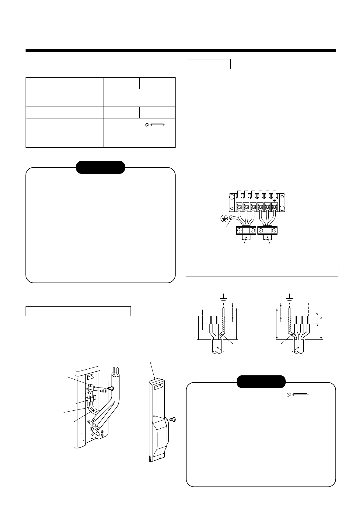
6
Terminal block
Screw
123LN
Connecting
cable
Power cable
ELECTRICAL WORK
For the air conditioner that has no power cable, connect
a power cable as mentioned belo w.
Model RAV-
Power supply
Maximum running current
Installation fuse rating
Power cable
SM560AT-E SM800AT-E
220 – 240 V
Single phase 50 Hz
12A 15A
25 A (D type )
H07 RN-F or 245 IEC 66
(2.5 mm2 or more)
CAUTION
• Wrong wiring may cause a burnout to some
electrical parts.
• Be sure to use the cord clamps attached to the
product.
• Do not damage or scratch the conductive core
and inner insulator of power and inter-connecting
cables when peeling them.
• Be sure to comply with local regulations of the
cable from outdoor unit to indoor unit.
(wire size and cabling method etc.)
• Use the power and Inter-connecting cables with
specified thickness, specified type and protective
devices required.
How to wire
1. Connect the connecting cable to the terminal as
identified with their respective numbers on the
terminal block of indoor and outdoor unit.
H07 RN-F or 245 IEC 66 (1.0 mm2 or more)
2. When connecting the connecting cable to the
outdoor unit terminal, prevent water coming in the
outdoor unit.
3. Insulate the unsheathed cords (conductors) with
electrical insulation tape. Process them so that they
do not touch any electrical or metal parts.
4. For inter connecting cable , do not use a wire jointed
to another on the way.
Use wires long enough to cover the entire length.
Stripping length power cord and connecting cabl e
<SM560AT-E>
How to remove the valve cover
1. Remove screws of the valve cover.
2. Pull the valve cover downward to remove it.
Piping cover
Cord clamp
Indoor/outdoor
connecting cables
Power cable
Valve cover
LN
10 10
30 30
10 10
40 40
Earth line Earth line
Power cable
Connecting
cable
123
(mm)
CAUTION
• The installation fuse (25A D type ) must
be used for the power supply line of this air
conditioner.
• Incorrect/incomplete wiring might cause an
electrical fire or smoke.
• Prepare the exclusive power supply for the air
conditioner.
• This product can be connected to the mains.
Connection to the fixed wiring :
A switch which disconnects all poles and has a
contact separation of at least 3 mm must be
incorporated in the fixed wiring.
15
Page 16
7
FINAL INSTALLATION CHECKS
Check and Test Operation
For R410A, use the leak detector e xclusiv ely manufactured for
HFC refrigerant (R410A, R134a, etc.).
The conventional leak detector for HCFC refrigerant (R22,
*
etc.) cannot be used because its sensitivity for HFC refrigerant
lowers to appro x. 1/40.
• Pressure of R410A is approx. 1.6 times higher than that of
R22.
If installation work is incompletely finished, a gas leakage may
occur when pressure rises during operation.
Therefore, be sure to test the piping connections for leakage.
• Check gas leakage at the flare nut connections, valve stem
cap connections and service port cap fittings with a leak
detector or soap water.
Piping
cover
Check points
of outdoor unit
Valve cover
Flare nut
connections
(Indoor unit)
CAUTION
When the remote controller is used for the first time, it accepts an operation approx. 5 minutes after the power
supply has been turned on.
It is not a trouble, b ut is because the setup of the remote controller is being checked.
For the second pow er-ON time and after, approx. 1 minute is required to start the operation by the remote controller .
Useful Functions (SM800AT-E only)
In addition to the code checking by remote controller of the indoor unit, troub les of the outdoor unit can be diagnosed by LED indications on the cycle control P.C. board of the outdoor unit. Utilize them for various checks.
For the check by remote controller of the indoor unit, refer to the Installation Manual of the indoor unit.
Before a check, confirm each bit of the DIP switch is set to OFF position.
Self-Diagnosis by LED Indication
LED indication and code checking
Cycle control P.C. board
LED indication
D800 ¡ : Red
¡ : Yellow
D801
¡ : Yellow
D802
¡ : Yellow
D803
¥ : Rapid flash
l : Go off
¡ : Go on
LED indication
D800 D801 D802 D803
¡
lll
ll
¡¡
l
l
¡¡¡
¡
l
l
¡¡
ll
¥ l
l ¥ l
¥¥
l
¥ l ¥
¡
ll
¡
l
¡
ll
ll
¡
l
¡¡
l
¡¡
ll
ll
¥
l
l
¡
l
¡
¡
l
¡
l
l
l
Cause
Heat exchanger sensor (TE) error
Suction sensor (TS) error
Discharge sensor (TD) error
High-pressure protection error
Outdoor temperature sensor (TO) error
DC outside fan error
Communication error between IPDU (Abnormal stop)
High-pressure release operation
Discharge temp. error
EEPROM error
Communication error between IPDU (No abnormal stop)
G-Tr shor t-circuit protection
Detect circuit error
Current sensor error
Comp. lock error
Comp. break down
16
Page 17
Installation/Servicing T ools
In the case of an air conditioner using R410A, in order to prevent any other refrigerant from being charged accidentally, service port diameter of the outdoor unit control valve (3 way valve) has been changed. (1/2 UNF 20 threads
per inch)
• In order to increase the pressure resisting strength of the refrigerant piping flare processing diameter and size of
opposite side of flare nuts has been changed. (for copper pipes with nominal dimensions 1/2 and 5/8)
Changes in the product and components
New tools for R410A
New tools for R410A
Gauge manifold
Charge hose
Electronic balance
for refrigerant charging
Torque wrench
(nominal diam. 1/2, 5/8)
Flare tool
(clutch type)
Gauge for projection adjustment
Vacuum pump adapter
Gas leakage detector
• Incidentally, the “refrigerant cylinder” comes with the refrigerant designation (R410A) and protector coating in the
U.S. ’s ARI specified rose color (ARI color code: PMS 507).
• Also, the “charge port and packing for refrigerant cylinder” require 1/2 UNF 20 threads per inch corresponding to
the charge hose’s port size.
Applicable to R22 model
××
×
××
××
×
××
¡
××
×
××
¡
——
¡
××
×
××
X
Changes
As pressure is high, it is impossible to measure by means of conventional
gauge. In order to prevent any other refrigerant from being charged, each
port diameter is changed.
In order to increase pressure resisting strength, hose materials and port
size are changed (to 1/2 UNF 20 threads per inch).
When purchasing a charge hose, be sure to check the port size.
As pressure is high and gasification speed is fast, it is difficult to read the
indicated value by means of charging cylinder, as air bubbles occur.
The sizes of opposite sides of flare nuts have been increased. Incidentally, a common wrench is used for nominal diameters 1/4 and 3/8.
By increasing the clamp bar’s receiving hole, strength of spring in the tool
has been improved.
Used when flare is made with using conventional flare tool.
Connected to the conventional vacuum pump. It is necessary to use an
adapter to prevent vacuum pump oil from flowing back to the charge hose.
The charge hose connecting part has two ports - one for conventional
refrigerant (7/16 UNF 20 threads per inch) and the other for R410A. If the
vacuum pump oil (mineral) mixes with R410A, sludge may occur and
damage the equipment.
Exclusive for HFC refrigerant.
17
Page 18
1
• Ensure that all Local, National and International regulations are satisfied.
• Read this “PRECAUTIONS FOR SAFETY” carefully before Installation.
• The precautions described below include the important items regarding safety. Observe them without fail.
• After the installation work, perform a trial operation to check for any prob lem.
Follow the Owner’s Manual to explain how to use and maintain the unit to the customer.
• Turn off the main power supply switch (or breaker) before the unit maintenance.
• Ask the customer to keep the Installation Manual together with the Owner’s Manual.
PRECAUTIONS FOR SAFETY
CAUTION New Refrigerant Air Conditioner Installation
RAV-SM1100AT-E
RAV-SM1400AT-E
• THIS AIR CONDITIONER ADOPTS THE NEW HFC REFRIGERANT (R410A) WHICH DOES NOT DE-
STROY OZONE LAYER.
The characteristics of R410A refrigerant are ; easy to absorb water, oxidizing membrane or oil, and its pressure
is approx. 1.6 times higher than that of refrigerant R22. Accompanied with the new refrigerant, refrigerating oil
has also been changed. Therefore, during installation work, be sure that water , dust, former refrigerant, or
refrigerating oil does not enter the refrigerating cycle.
To prevent charging an incorrect refrigerant and refrigerating oil, the sizes of connecting sections of charging
port of the main unit and installation tools are charged from those for the conventional refrigerant.
Accordingly the exclusive tools are required for the new refrigerant (R410A).
For connecting pipes, use new and clean piping designed for R410A, and please care so that water or dust
does not enter. Moreover, do not use the existing piping because there are problems with pressure-resistance
force and impurity in it.
CAUTION To Disconnect the Appliance from Main Power Supply.
This appliance must be connected to the main power supply by means of a switch with a contact separation of
at least 3 mm.
The installation fuse (25A D type ) must be used for the power supply line of this conditioner.
WARNING
• Ask an authorized dealer or qualified installation professional to install/maintain the air
conditioner.
Inappropriate installation may result in water leakage, electric shock or fire.
• Turn off the main power supply switch or breaker before attempting any electrical work.
Make sure all power switches are off. Failure to do so may cause electric shock.
• Connect the connecting cable correctly.
If the connecting cable is connected in a wrong way, electric parts may be damaged.
• When moving the air conditioner for the installation into another place, be very careful not
to enter any gaseous matter other than the specified refrigerant into the refrigeration cycle.
If air or any other gas is mixed in the refrigerant, the gas pressure in the refrigeration cycle becomes abnormally high and it may resultingly causes pipe burst and injuries on persons.
• Do not modify this unit by removing any of the safety guards or by by-passing any of the
safety interlock switches.
• Exposure of unit to water or other moisture before installation may cause a short-circuit of
electrical parts.
Do not store it in a wet basement or expose to rain or water.
18
Page 19
• After unpacking the unit, examine it carefully if there are possible damage.
• Do not install in a place that might increase the vibration of the unit.
• To avoid personal injury (with sharp edges), be careful when handling parts.
• Perform installation work properly according to the Installation Manual.
Inappropriate installation may result in water leakage, electric shock or fire.
• When the air conditioner is installed in a small room, provide appropriate measures to
ensure that the concentration of refrigerant leakage occur in the room does not exceed the
critical level.
• Install the air conditioner securely in a location where the base can sustain the weight
adequately.
• Perform the specified installation work to guard against an earthquake .
If the air conditioner is not installed appropriately, accidents may occur due to the falling unit.
• If refrigerant gas has leaked during the installation work, ventilate the room immediately.
If the leaked refrigerant gas comes in contact with fire, noxious gas may generate.
• After the installation work, confirm that refrigerant gas does not leak.
If refrigerant gas leaks into the room and flows near a fire source, such as a cooking range, noxious gas
might generate.
• Electrical work must be performed by a qualified electrician in accordance with the Installa-
tion Manual. Make sure the air conditioner uses an exclusive power supply.
An insufficient power supply capacity or inappropriate installation may cause fire.
• Use the specified cables for wiring connect the terminals securely fix. To prevent external
forces applied to the terminals from affecting the terminals.
• Be sure to provide grounding.
Do not connect ground wires to gas pipes, water pipes, lightning rods or g round wires for telephone cables.
• Conform to the regulations of the local electric company when wiring the power supply.
Inappropriate grounding may cause electric shock.
• Do not install the air conditioner in a location subject to a risk of exposure to a combustible
gas.
If a combustible gas leaks, and stays around the unit, a fire may occur.
RAV-SM1100AT-E
Required tools for installation work
1) Philips screw driver
2) Hole core drill (65 mm)
3) Spanner
4) Pipe cutter
5) Knife
6) Reamer
7) Gas leak detector
8) Tape measure
9) Thermometer
10) Mega-tester
11) Electro circuit tester
12) Hexagonal wrench
13) Flare tool
14) Pipe bender
15) Level vial
16) Metal saw
R410A (Special requirement)
17) Gauge manifold
(Charge hose : R410A special requirement)
18) Vacuum pump
(Charge hose : R410A special requirement)
19) Torque wrench
1/4 (17 mm) 16 N•m (1.6 kgf•m)
3/8 (22 mm) 42 N•m (4.2 kgf•m)
1/2 (26 mm) 55 N•m (5.5 kgf•m)
5/8 (15.9 mm) 120 N•m (12.0 kgf•m)
20) Copper pipe gauge adjusting projection margin
21) Vacuum pump adapter
19
Page 20
2
ACCESSORY AND REFRIGERANT
Accessory and Installation Parts Refrigerant Piping
• Piping kit used for the conventional refrigerant cannot
be used.
1
Outdoor unit
Installation manual x 1
Drain nipple
2
Waterproof rubber cap
3
Protective bush
4
Guard material for
passage part
• Use copper pipe with 0.8 mm or more thickness for
Ø9.5 mm.
Use copper pipe with 1.0 mm or more thickness for
Ø15.9 mm.
• Flare nut and flare works are also different from those
of the conventional refrigerant. Take out the flare nut
attached to the main unit of the air conditioner, and
use it.
3
SELECTION OF INSTALLATION
Before installation
Be careful to the following items before installation.
Length of refrigerant pipe
Length of refrigerant pipe
connected to
indoor/outdoor unit
20m or shorter
21m to 50m
*
* Caution at addition of refrigerant
When the total length of refrigerant pipe exceeds
20m, add 40g/m of refrigerant and the maximum total
length of pipe is 50m.
(Max. amount of additional refrigerant is 1200g.)
Charge the refrigerant accurately. Overcharge may
cause a serious trouble of compressor .
Addition of refrigerant is
unnecessary at the local site.
<Addition of refrigerant>
Add 40g of refrigerant for every
1m of pipe which exceeds 20m.
Item
Air purge
• For air purge, use a vacuum pump.
• Do not use refrigerant charged in the outdoor unit for
air purge. (The refrigerant for air purge is not contained in the outdoor unit.)
Electrical cabling
• Be sure to fix the power cables and indoor/outdoor
connecting cables with clamps so that they do not
contact with the cabinet, etc.
20
Page 21

Installation Place
500
or more
150
or more
Necessary Space for Installation
• A place which provides a specified space around the
outdoor unit.
• A place where the operation noise and discharged air
are not given to your neighbors .
• A place that is not exposed to a strong wind.
• A place that does not block a passage.
• When the outdoor unit is installed in an elev ated
position, be sure to secure its feet.
• There must be sufficient space for carrying in the
unit.
• A place where the drain water does not make an y
problem.
CAUTION
1. Install the outdoor unit at a place where dis-
charge air is not blocked.
2. When an outdoor unit is installed in a place that
is always exposed to a strong wind like a coast
or on a high storey of a building, secure a
normal fan operation by using a duct or a wind
shield.
3. When installing the outdoor unit in a place that is
constantly exposed to a strong wind such as the
upper stairs or rooftop of a building, apply the
windproof measures referring to the follo wing
examples.
1) Install the unit so that its
discharge port faces to the
wall of the building. Keep a
distance 500 mm or more
between the unit and the
wall surface .
500
Obstacle at rear side
<Upper side is free>
1. Single unit installation
2. Obstacles at both right and left sides.
200
or more
150
or more
The height of the
obstacle should be
lower than the height
of the outdoor unit.
300
or more
3. Serial installation of two or more units
150
or more
The height of the obstacle should be lower
than the height of the outdoor unit.
300
or more
300
or more
<Obstacle also at the upper side>
150
300
or more
or more
200 or more
2) Supposing the wind direction during the
operation season of the air conditioner, install
the unit so that the discharge port is set at
right angle to the wind direction.
Strong
wind
Strong
wind
4. Installation in the following places ma y result in
some troubles. Do not install the unit in such
places below.
• A place full of machine oil.
• A place full of sulphuric gas.
• A place where high-frequency radio waves are
likely to be generated as from audio quipment,
welders, and medical equipment.
Obstacle at front side
<Upper side is free>
1. Single unitIn installation
2. Serial installation of two or more units
21
500
1000
or more
or more
Page 22
15 or less
3
SELECTION OF INSTALLATION
<Obstacle also at the upper side>
1000
or more
1000
or more
Obstacles at both front and rear sides
Open the upper side and both right and left sides.
The height of obstacle at both front and rear side,
should be lower than the height of the outdoor unit.
<Standard installation>
1. Single unit installation
150
or more
Installation of Outdoor Unit
• Before installation, check strength and horizontality of
the base so that abnormal sound does not generate.
• According to the following base diagram, fix the base
firmly with the anchor bolts.
(Anchor bolt, nut: M10 x 4 pairs)
600150 150
430
Drain hole
40
365
400
Knockout hole
Set the out margin of the anchor bolt to 15mm or less.
Drain nipple mounting hole
1000
or more
2. Serial installation of two or more units
200
or more
300
or more
300
or more
1000
or more
Serial installation at front and rear sides
Open the upper side and both right and left sides.
The height of obstacle at both front and rear sides
should be lower than the height of the outdoor unit.
<Standard installation>
• In case of drainning through the drain hose, attach
the following drain nipple and the waterproof rubber
cap, and use the drain hose (Inner diam.: 16mm) sold
on the market. And also seal the screws securely with
silicone material, etc. so that w ater does not drop
down. Some conditions may cause dewing or dripping of water.
Drain nipple Waterproof rubber cap
Knockout hole
Open
Waterproof rubber cap
Drain nipple
1000
or more
300
or more
1500
or more
2000
or more
200
or more
• When there is a possibility of freezing of drain at the
cold district or a snowfall area, be careful for drainage
ability of drain. The dr ainage ability increases when a
knockout hole on the base plate is opened. (Open the
knockout hole to outside using a screwdriver, etc.)
22
Page 23
Optional Installation Parts (Local Procure)
Knockout of Pipe Cover
Parts name
Refrigerant piping
A
Liquid side : Ø9.5 mm
Gas side : Ø15.9 mm
Pipe insulating material
B
(polyethylene foam, 6 mm thick)
C
Putty, PVC tapes
Refrigerant Piping Connection
CAUTION
TAKE NOTICE THESE IMPORTANT
4 POINTS BELOW FOR PIPING WORK
1. Keep dust and moisture away from inside the
connecting pipes.
2. Tightly connect the connection between pipes
and the unit.
3. Evacuate the air in the connecting pipes using
VACUUM PUMP.
4. Check gas leak at connected points.
<Piping connection>
Liquid side
Outer diameter Thickness
Ø9.5 0.8
Outer diameter Thickness
Gas side
Ø15.9 1.0
Q’ty
Each one
1
Each one
Rear direction
Pipe cover
Side direction
Front direction
Down direction
Knockout procedure
• The indoor/outdoor connecting pipes can be connected to 4 directions.
Take off the knock out part of the pipe cover in which
pipes or wires pass through the base plate.
• As shown in the figure, do not remove the pipe cover
from the cabinet so that the knockout hole can be
easily punched. To knock out, it is easily taken off by
hands by punching a position at the lower side of 3
connected parts with screwdriver along the guide
line.
• After marking the knockout hole, remove the burr and
mount the attached protective bush and guard
material for pass-through part in order to protect
pipes and wires.
For Reference
If a heating operation would be continuously performed
for a long time under the condition that the outdoor
temperature is 0°C or lower, draining of defrosted water
may be difficult due to freezing of the bottom plate,
resulting in a trouble of the cabinet or fan.
It is recommended to procure an anti-freeze heater
locally for a safety installation of the air conditioner.
For details, contact the dealer.
After connecting the pipes, be sure to mount the pipe
cover. The pipe cover is easily mounted by cutting off
the slit at the lower part of the pipe cover.
23
Page 24
3
SELECTION OF INSTALLATION
How to remove the front panel
1. Remove scre ws of the front panel.
2. Pull the front panel downward.
Removing the front panel, the electric parts appear at
the front side.
• The metal pipes are attachable to the piping holes.
If the size of the used power pipe does not match with
the hole, adjust the hole size to match with pipe size.
• Be sure to fix the power cable and indoor/outdoor
connecting cable with bundling band sold on the
market so that they do not mak e contact with the
compressor and discharge pipe.
(Temperature of the compressor and discharge pipe
becomes high.)
4
REFRIGERANT PIPING
Pipe Forming/End Positioning
Flaring
1. Cut the pipe with a pipe cutter.
In order to avoid the force applied to on the connecting section, be sure to fix the cables to the cord
clamps provided on the pipe valve fixing plate and the
electric parts box.
Electric parts box
Cord clamp
* In case of flaring for R410A with the conventional
flare tool, pull it out approx. 0.5 mm more than that of
R22 to adjust to the specified flare size. The copper
pipe gauge is useful for adjusting projection margin
size.
A
Front panel
Pipe valve
fixing plate
Piping
hole
90˚
2. Insert a flare nut into the pipe, and flare the pipe.
As the flaring sizes of R410A differ from those of
refrigerant R22, the flare tools newly manufactured
for R410A are recommended.
However, the conventional tools can be used by
adjusting projection margin
of the copper pipe.
Obliquity Roughness Warp
• Flaring siz e : A (Unit : mm)
+0
A
Outer dia. of copper pipe
6.4
9.5
12.7
15.9
R410A R22
9.1 9.0
13.2 13.0
16.6 16.2
19.7 19.4
- 0.4
• Projection margin in flaring : B (Unit : mm)
Rigid (Clutch type)
Outer dia.
of copper
pipe
B
6.4
9.5
12.7
15.9
Imperial (Wing nut type)
Outer dia. of copper pipe
R410A tool used
R410A R22
0 to 0.5
0 to 0.5
0 to 0.5
0 to 0.5
6.4
9.5
12.7
15.9
(Same as left)
(Same as left)
(Same as left)
(Same as left)
Conventional tool used
R410A R22
1.0 to 1.5 0.5 to 1.0
1.0 to 1.5 0.5 to 1.0
1.0 to 1.5 0.5 to 1.0
1.0 to 1.5 0.5 to 1.0
R410A R22
1.5 to 2.0 1.0 to 1.5
1.5 to 2.0 1.0 to 1.5
2.0 to 2.5 1.5 to 2.0
2.0 to 2.5 1.5 to 2.0
24
Page 25
Tightening of Connecting Part
(Unit: N•m)
Outer dia. of copper pipe
6.4 mm (diam.)
9.5 mm (diam.)
12.7 mm (diam.)
15.9 mm (diam.)
Flare at
indoor unit side
• Align the centers of the connecting pipes and tighten
the flare nut strong as far as possib le with your
fingers.
Then fix the nut with a spanner and tighten it with
torque wrench as shown in the figure.
Tightening torque
14 to 18 (1.4 to 1.8 kgf•m)
33 to 42 (3.3 to 4.2 kgf•m)
50 to 62 (5.0 to 6.2 kgf•m)
63 to 77 (6.3 to 7.7 kgf•m)
Flare at
outdoor unit side
REQUIREMENT
1. Do not put the spanner on the cap. The valve
may be broken.
2. If applying excessive torque, the nut may be
broken according to some installation conditions.
• After the installation work, be sure to check gas leak
of connecting part of the pipes with nitrogen.
Cover
Half union or packed valve Flare nut
Externally
threaded side
Fix with spanner.
Tighten with torque wrench.
Internally
threaded side
• As shown in the figure, be sure to use a double
spanner to loosen or tighten the flare nut of the valve
at gas side. If using a single spanner, the nut cannot
be tightened with necessary tightening torque.
On the contrary, use a single spanner to loosen or
tighten the flare nut of the valve at liquid side.
Cover
Cap
Piping valve
Loosened
Tightened
• Pressure of R410A is higher than that of R22
(Approx. 1.6 times). Therefore, using a torque
wrench, tighten the flare pipe connecting sections
which connect the indoor/outdoor units at the specified tightening torque. Incomplete connections may
cause not only a gas leak, but also a trouble of the
refrigeration cycle.
Do not apply refrigerating machine oil to
the flared surface.
Flare nut
Valve at gas side
25
Page 26
5
EVACUATING
Air Purge
This air conditioner can be installed up to the connecting pipe length and height difference in the following table.
Max. connecting
pipe length (m)
50
With respect to the preservation of terrestrial environment, adopt “Vacuum pump” for air purge (Evacuate air in
the connecting pipes) when installing the unit.
• Do not discharge the refrigerant gas to the atmosphere to preserve the terrestrial environment.
• Use a vacuum pump to discharge the air (nitrogen, etc.) remained in the set. If the air remains, the capacity
may decrease.
For the vacuum pump, be sure to use one with backflow preventer so that the oil in the pump does not backflow
into the pipe of the air conditioner when the pump stops. (If oil in the vacuum pump is put in an air conditioner
including R410A, it may cause trouble on the refrigeration cycle .)
Outdoor unit at upper side Outdoor unit at lower side
Height difference (m)
30 15
Hexagonal wrench size
4 mm
Vacuum pump
As shown in the right figure, connect the charge hose after the manifold valve are closed completely.
Attach the connecting port of the charge hose with a projection to push the valve core (setting pin) to the charge port of the set.
Open handle Low fully.
Turn ON the vacuum pump (*1)
Loosen the flare nut of the packed valve (Gas side) a little to check the air passes through. (*2)
Tighten the flare nut again.
Execute vacuuming until the compound pressure gauge indicates –101kPa (–76cmHg). (*1)
Close handle Low completely.
Turn OFF the vacuum pump.
Leave the vacuum pump as it is for 1 or 2 minutes, and check the indicator of the compound pressure gauge does not return.
Open fully the valve stem or the valve handle. (First, at liquid side, then gas side)
Disconnect the charge hose from the charge port.
Tighten valve and caps of the charge port surely.
26
Page 27
Compound pressure gauge
–101kPa
(–76cmHg)
Handle Lo
Charge hose
(For R410A only)
Service port
(Valve core (Setting pin))
Pressure gauge
Manifold valve
Handle Hi
(Keep fully closed)
Charge hose
(For R410A only)
Vacuum pump adapter
for counter-flow prevention
(For R410A only)
Handle position
Closed completely
Handle
Opened fully
Packed valve at gas side
How to open the valve
Charge port
How to close the valve
Vacuum
pump
Valve unit
Handle
Pull out the handle and
using cutting pliers, etc.
turn it counterclockwise
by 90˚. (Open fully)
Flare nut
*1. Use the vacuum pump, vacuum pump adapters,
and gauge manifold referring to the manuals
attached to each tool before using them. For the
vacuum pump, check oil is filled up to the specified
line of the oil gauge.
*2. While the air is purged, check again that the
connecting port of charge hose, which has a
projection to push the valve core, is firmly connected to the charge port.
Valve handling precautions
• Open the valve stem or the handle until it strikes
the stopper. It is unnecessary to apply further
force.
• Securely tighten the cap with a torque wrench.
• Cap tightening torque
14 to 18N•m (1.4 to 1.8kgf•m)
33 to 42N•m (3.3 to 4.2kgf•m)
33 to 42N•m (3.3 to 4.2kgf•m)
20 to 25N•m (2.0 to 2.5kgf•m)
14 to 18N•m (1.4 to 1.8kgf•m)
Valve size
Charge port
Ø6.4
Ø9.5
Ø12.7
Ø15.9
Charge port
Valve unit
Push in handle and
turn clockwise by 90˚.
(Close fully)
Flare nut
27
Page 28

6
ELECTRICAL WORK
For the air conditioner that has no power cable, connect
a power cable as mentioned belo w.
Model RAV-
Power supply
Maximum running current
Installation fuse rating
Power cable
SM1100AT-E SM1400AT-E
220 – 240 V
Single phase 50 Hz
22.0 A 22.8 A
25 A (D type )
H07 RN-F or 245 IEC 66
(2.5 mm2 or more)
CAUTION
• Wrong wiring may cause a b urn-out to some
electrical parts.
• Be sure to use the cord clamps attached to the
product.
• Do not damage or scratch the conductive core
and inner insulator of power and inter-connecting
cables when peeling them.
• Be sure to comply with local regulations of the
cable from outdoor unit to indoor unit.
(wire size and cabling method etc.)
• Use the power and Inter-connecting cables with
specified thickness, specified type and protective
devices required.
Stripping length power cord and connecting cabl e
LN
10 10
40 30
10 10
50 40
Earth line Earth line
Power cable
Connecting
cable
123
(mm)
CAUTION
• The installation fuse (25A D type ) must
be used for the power supply line of this air
conditioner.
• Incorrect/incomplete wiring might cause an
electrical fire or smoke.
• Prepare the exclusive power supply for the air
conditioner.
• This product can be connected to the mains.
Connection to the fixed wiring :
A switch which disconnects all poles and has a
contact separation of at least 3 mm must be
incorporated in the fixed wiring.
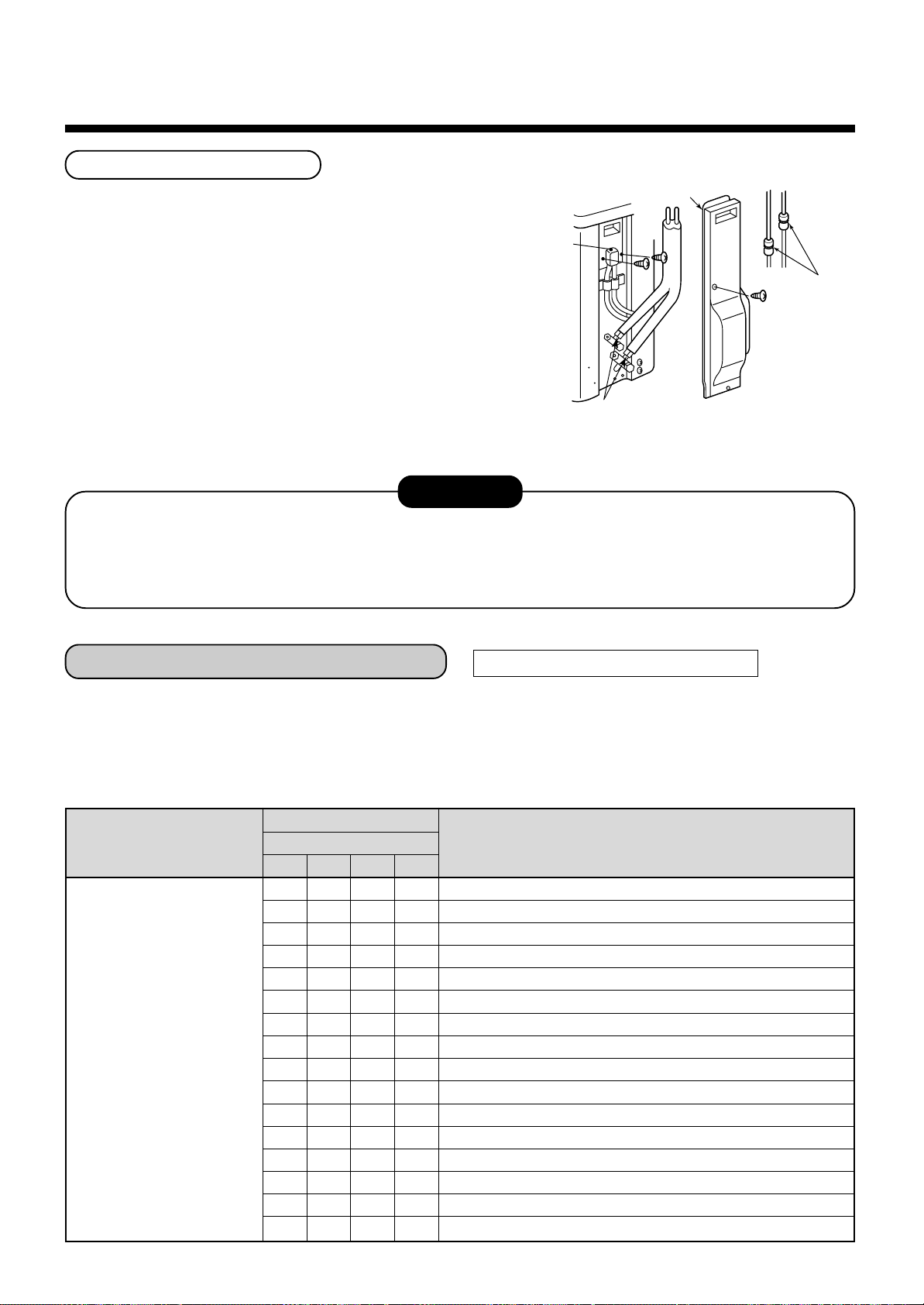
How to wire
1. Connect the connecting cable to the terminal as
identified with their respective numbers on the
terminal block of indoor and outdoor unit.
H07 RN-F or 245 IEC 66 (1.0 mm2 or more)
2. When connecting the connecting cable to the
outdoor unit terminal, prevent water coming in the
outdoor unit.
3. Insulate the unsheathed cords (conductors) with
electrical insulation tape. Process them so that they
do not touch any electrical or metal parts.
4. For inter connecting cable , do not use a wire jointed
to another on the way.
Use wires long enough to cover the entire length.
Power supply
terminal block
LN
Earth screw
To Indoor unit
terminal block
123
Connecting cablePower cable
28
Page 29

7
FINAL INSTALLATION CHECKS
Check and Test Operation
For R410A, use the leak detector e xclusiv ely manufactured for HFC refrigerant (R410A, R134a, etc.).
The conventional leak detector for HCFC refrigerant (R22, etc.) cannot be used because its sensitivity for HFC
*
refrigerant lowers to approx. 1/40.
• Pressure of R410A is approx. 1.6 times higher than that of R22.
If installation work is incompletely finished, a gas leakage may occur when pressure rises during operation.
Therefore, be sure to test the piping connections for leakage.
• Check gas leakage at the flare nut connections, valve stem cap connections and service port cap fittings with a
leak detector or soap water.
CAUTION
When the remote controller is used for the first time, it accepts an operation approx. 5 minutes after the power
supply has been turned on.
It is not a trouble, b ut is because the setup of the remote controller is being checked.
For the second pow er-ON time and after, approx. 1 munute is required to start the operation by the remote controller.
Useful Functions
In addition to the code checking by remote controller of the indoor unit, troub les of the outdoor unit can be diagnosed by LED indications on the cycle control P.C. board of the outdoor unit. Utilize them for various checks.
For the check by remote controller of the indoor unit, refer to the Installation Manual of the indoor unit.
Before a check, confirm each bit of the DIP switch is set to OFF position.
LED indication and code checking
Cycle control P.C. board
LED indication
D800 ¡ : Red
¡ : Y ello w
D801
¡ : Y ello w
D802
¡ : Y ello w
D803
¥ : Rapid flash
l : Go off
¡ : Go on
D800 D801 D802 D803
LED indication
¡
ll
¡¡
l
l
¡¡¡
¡
l
l
¡¡
ll
¥ l
l ¥ l
¥¥
l
¥ l ¥
lll
¡
ll
¡
¡
l
ll
ll
¡
¡¡
l
l
¡¡
ll
ll
l
¥
l
¡
l
¡
¡
l
¡
l
l
l
Self-Diagnosis by LED Indication
Cause
Heat exchanger sensor (TE) error
Suction sensor (TS) error
Discharge sensor (TD) error
High-pressure protection error
Outdoor temperature sensor (TO) error
DC outside fan error
Communication error between IPDU (Abnormal stop)
High-pressure release operation
Discharge temp. error
EEPROM error
Communication error between IPDU (No abnormal stop)
G-Tr shor t-circuit protection
Detect circuit error
Current sensor error
Comp. lock error
Comp. break down
29
Page 30

7
FINAL INSTALLATION CHECKS
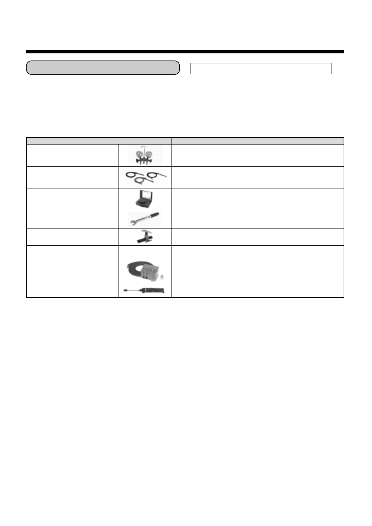
Installation/Servicing T ools
In the case of an air conditioner using R410A, in order to prevent any other refrigerant from being charged accidentally, service port diameter of the outdoor unit control valve (3 way valve) has been changed. (1/2 UNF 20 threads
per inch)
• In order to increase the pressure resisting strength of the refrigerant piping flare processing diameter and size of
opposite side of flare nuts has been changed. (for copper pipes with nominal dimensions 1/2 and 5/8)
Changes in the product and components
New tools for R410A
New tools for R410A
Gauge manifold
Charge hose
Electronic balance
for refrigerant charging
Torque wrench
(nominal diam. 1/2, 5/8)
Applicable to R22 model
××
×
××
××
×
××
¡
××
×
××
Changes
As pressure is high, it is impossible to measure by means of conventional
gauge. In order to prevent any other refrigerant from being charged, each
port diameter is changed.
In order to increase pressure resisting strength, hose materials and port
size are changed (to 1/2 UNF 20 threads per inch).
When purchasing a charge hose, be sure to check the port size.
As pressure is high and gasification speed is fast, it is difficult to read the
indicated value by means of charging cylinder, as air bubbles occur.
The size of opposite sides of flare nuts have been increased. Incidentally,
a common wrench is used for nominal diameters 1/4 and 3/8.
Flare tool
(clutch type)
Gauge for projection adjustment
Vacuum pump adapter
Gas leakage detector
• Incidentally, the “refrigerant cylinder” comes with the refrigerant designation (R410A) and protector coating in the
U,S. ’s ARI specified rose color (ARI color code: PMS 507).
• Also, the “charge port and packing for refrigerant cylinder” require 1/2 UNF 20 threads per inch corresponding to
the charge hose’s port size.
¡
——
¡
××
×
××
By increasing the clamp bar’s receiving hole, strength of spring in the tool
has been improved.
Used when flare is made with using conventional flare tool.
Connected to the conventional vacuum pump. It is necessary to use an
adapter to prevent vacuum pump oil from flowing back to the charge hose.
The charge hose connecting part has two por ts-one for conventional
refrigerant (7/16 UNF 20 threads per inch) and one for R410A.
If the vacuum pump oil (mineral) mixes with R410A a sludge may occur
and damage the equipment.
Exclusive for HFC refrigerant.
30
Page 31

ACCESSORIES (SOLD SEPARATELY)
Remote controller
PRECAUTIONS FOR SAFETY
WARNING
WARNINGS ABOUT INSTALLA TION
• Make sure to ask the qualified installation professional in electric work to install
the air conditioner .
If the air conditioner is inappropriate installed by yourself , it may cause water leak,
electric shock, fire, and so on.
• Be sure to provide grounding.
Do not connect ground wires to gas pipes, water pipes, lightning rods or ground
wires for telephone cab les .
CAUTION
TO DISCONNECT THE APPLIANCE FROM THE MAINS SUPPLY
This appliance must be connected to the mains by means of a switch with a
contact separation of at least 3 mm.
The installation fuse (25A D type ) must be used for the power
supply line of this conditioner.
WARNINGS ABOUT OPERATION
• Cleaning of the air filter and other parts of the air filter involves dangerous work in
high places, so be sure to hav e a service person do it. Do not attempt it yourself.
The cleaning diagram for the air filter is there for the service person, and not for
the customer .
• Avoid cooling the room too strong or exposing the human body to cool breeze for
a long time as it is bad for the health.
• When you notice something abnormal with the air conditioner (smells like something scorching, poor cooling, etc.), immediately turn off the main switch, the
circuit breaker, from the mains to stop the air conditioner, and contact the dealer.
If the air conditioner is continuously operated with something abnormal, it may
cause machine failure, electric shock, fire, and so on.
WARNINGS ABOUT MOVEMENT AND REPAIR
• Do not move or repair any unit by yourself.
Since there is high voltage inside the unit, you may get electric shock when
removing the cov er and main unit.
• Whenev er the air conditioner needs repair, make sure to ask the dealer to do it.
If it is repaired imperfectly, it may cause electric shock or fire.
• When moving the air conditioner for re-installing at another place , ask the dealer
to do it. If it is imperfectly installed, it may cause electric shock or fire .
RAV-SM561BT-E/RAV-SM801BT-E
RAV-SM1101BT-E/RAV-SM1401BT-E
31
Page 32

RAV-SM561BT-E/RAV-SM801BT-E
CAUTION
CAUTIONS ABOUT INSTALLATION
• Be sure to confirm the following cautions.
• Certainly lay the drain hose for perfect draining.
Bad drainage may cause flooding in the house and getting furniture
wet.
• Make sure to connect the air conditioner to an exclusive power
supply of the rated voltage, otherwise the unit may break down or
cause a fire.
• Do not install the unit in a place where inflammable gas may leak.
If inflammable gas accumulates around the unit, it may cause a fire.
CAUTIONS ABOUT OPERATION
• Carefully read this manual before starting the air conditioner. There
are many important things to keep in mind for daily operation.
• Do not use this air conditioner for special purposes such as preserving food, precision instruments, art objects, breeding animals,
growing potted plants, etc.
• Av o id exposing potted plants and animals to the wind of the air
conditioner , since it badly affects the health and growth of them.
• When the air conditioner is operated with a combustion appliance in
the same place, be careful of ventilation to let fresh air enter the
room.
Poor ventilation causes oxygen shortage.
• Do not place any combustion appliance in a place where it is directly
exposed to the wind of air conditioner, otherwise it may cause
imperfect combustion.
• When the air conditioner is used in a closed room, be careful of
sufficient ventilation of the room. Poor ventilation causes oxygen
shortage.
RAV-SM1101BT-E/RAV-SM1401BT-E
• Do not touch any switches with w et finger, otherwise you may get an
electric shock.
• If the air conditioner won’t be used for a considerab ly long time , turn
off the main switch or the circuit break er, for safety.
• Check the concrete blocks, etc. of the base of the outdoor unit
occasionally.
If the base is left damaged or deteriorated, the unit may topple over
and inflict an injury to a person as the worst case.
• Do not put anything on the outdoor unit nor step onto it. If you do so,
it may not only topple over the unit but also injure yourself.
• To make the air conditioner operate in its original performance,
operate it within the range of the operating temperature specified in
the instructions.
Otherwise it may cause a malfunction, or water leak from the unit.
• Prevent an y liquid from falling into the remote controller. Do not spill
juice, water or any kind of liquid.
ITALIANGREEK FRENCHGERMANDUTCH ENGLISH
32
Page 33

PARTS NAME
Indoor unit
Supply air grille
NOTE :
Parts marked with indicate
the locally procured parts.
XXX
Connecting duct
Indoor unit
Duct flange
Air filter
Supply air chamber
Outdoor unit
Air inlet (Side and rear)
Canvas
Return air grille
REMOTE CONTROLLER
Remote controller
Air outlet
Pipes and electric wires
33
Page 34

PARTS NAME OF REMOTE CONTROLLER
Display section
All display items are shown in right figure for the explanation.
Only selected contents are displayed in actual operation.
• When turning on the leakage breaker at the first time, [SET D ATA]
flashes on the display part of the remote controller. While this
display is flashing, the model is being automatically confirmed.
Accordingly, wait for a while after [SET DATA] displa y has disap-
peared, and then use the remote controller .
1
9
SET DATA
SETTING
SET
TEST
CODE No.
UNIT No.
R.C. No.
UNIT
CL
Display
section
Operation
section
2
3
4
5
6
7
8
1
SET DATA display
Displayed during setup a timer.
2
Operation mode display
The selected operation mode is display ed.
3
CHECK display
Displayed while the protective device works
or a trouble occurs.
4
Timer time display
Set time by the timer is displa y ed.
(When a trouble occurs, the check code is
displayed.)
5
Timer SETIN setup display
When pushing the Timer SET b utton, the
display of the timer is selected in order of
[OFF] → [OFF] repeat OFF timer
→ [ON]
→ No display.
6
Filter display
If “FILTER ” is displayed, clean the air
filter.
7
UP/DOWN grille display
8
Ventilator operation displa y
9
Flap position display
SET DATA
SETTING
TEST
UNIT No.
R.C. No.
10
11
12
13
14
15
16
CODE No.
10
11
12
13
14
15
16
SWING display
Displayed during up/do wn movement of the
flap.
Set up temperature display
The selected set up temp. is displayed.
Remote controller sensor display
Displayed while the sensor of the remote
controller is working.
PRE-HEAT display
Displayed when the heating operation starts or
defrost operation is carried out.
While this indication is displayed, the indoor
fan stops or the mode changes in LOW.
No function display
Displayed if there is no function even if the
button is pushed.
Fan mode display
The selected fan mode is displayed.
(AUTO)
(HIGH)
(MED.)
(LOW)
TEST run display
Displayed during a test run.
34
Page 35

Operation section
Push each button to select a desired operation.
• The details of the operation needs to be set up once, the same states are used by pushing
button.
1
7
8
2
3
9
4
5
1
Fan mode button
Selects a fan mode.
2
Timer set button
TIMER SET button is used when the timer is
set up.
3
Check button
CHECK button is used for chec k oper ation.
During normal operation, do not use this
button.
4
Fan button
FAN button is used when a fan which is sold on
the market or etc. is connected.
• If “No function” is displayed on the remote
controller when pushing the FAN button, a
fan is not connected.
5
Filter reset button
Resets (Erases) “FILTER ” display.
SET
CL
UNIT
6
8
When the button is pushed, operation starts,
and it stops by pushing the button again.
When the operation stops, the operation lamp
and all displays disappear.
9
Operation select button
Selects operation mode.
10
Set up temperature button
Adjusts required room temperature.
Set required set temperature by pushing
FILTER UP/DOWN button
(No function display)
button
or .
10
6
UNIT and AUTO flap button
No function
7
Operation lamp
Lamp is lit during the operation. Lamp is off
when stopped.
It flashes when operating a protection device
or abnormal occurred.
OPTION :
Remote controller sensor
Usually the TEMP. sensor of the indoor unit measures a temperature. A temperature around the
remote controller can also be measured.
For details, contact the dealer from which you have
purchased the air conditioner.
35
Page 36

CORRECT USAGE
When you use the air conditioner f or the first time or when you change SET DATA value, fo llow the procedure
below. From the next time, the operation will start as set state by pushing the button.
Preparation
Turn on the main power switch and/or the leakage breaker.
• When the power supply is turned on, display section is displa yed on the remote controller.
After the power supply is turned on, the remote controller does not accept an operation for appro x. 1 minute,
*
but it is not a f ailure.
REQUIREMENT
• While using the air conditioner , operate it only with b utton without turning off the main
power switch and the leakage breaker.
• When starting the operation after stop for a long time, turn on the main power switch for 12 hours or
more before start. (This is required to turn on the compressor case heater for w arming in order to
prevent o verload on the compressor when activating the outdoor unit.)
1
3
2
UNIT
CL
SET
1
Push button.
The operation lamp goes on, and the operation starts.
2
Select an operation mode with the “MODE” button.
One push of the button, in each time the displa y
changes in the order shown on the right.
• In HEAT mode, if the room temperature reaches to the set temperature, the outdoor unit stops and
the air flow becomes LOW and the air volume decreases.
• In the defrost mode, the fan stops so that cool air is not discharged and PRE-DEF is displayed.
3
Select air volume with “FAN ” button.
One push of the button, in each time the displa y
changes in the order shown on the right.
AUTO HEAT DRY COOL FAN
AUTO
4
LOW MED. HIGH
• When air volume is “AUTO ”, air volume diff ers according to the room temper ature .
• In DRY mode, “AUTO ” is displayed and the air volume is LOW.
• In heating operation, if the room temperature is not heated sufficiently with fan mode “LOW ” operation, select “MED. ” or “HIGH ” operation.
4
Determine the set up temperature by pushing the “TEMP. ” or “TEMP. ” button.
Stop
Push button.
The operation lamp goes off, and the operation stops .
36
Page 37

AUTOMATIC OPERATION (Auto Changeover)
When you set the air conditioner in mode or switch over from AUTO operation, it will automatically select
either cooling, heating, or fan only operation depending on the indoor room temperature .
Start
1
Push this button to start the air conditioner.
2
Mode select button (MODE)
Select Auto .
3
T emperature button
Set the desired temperature.
• In case of cooling, start the operation after approx. 1 min ute .
• In case of heating, starts the operation after approximately 3 to 5 minutes.
• When you select the Auto mode , it is unnecessary to set the f an speed.
The fan speed display will sho w and fan speed will be automatically controlled.
• After heating operation stops, FAN operation may continue for approx. 30 seconds.
• When the room temperature reaches the set temperature and the outdoor unit stops, the LOW wind is
discharged and the air volume decreases e xcessively. During defrost operation, the fan stops so that cool
air is not discharged and is displayed.
• If the Auto mode is uncomf ortable, you can select the desired conditions manually.
button
NOTE
When restarting the operation after stop
• When restarting the operation immediately after stop, the air conditioner does not operate for appro x. 3
minutes to protect a compressor .
Stop
Push button.
Push this button again to stop the air conditioner.
37
Page 38

TIMER OPERATION
A type of timer operation can be selected from the following three types.
OFF timer : The oper ation stops after the set time has passed.
Repeat OFF timer : Every time, the operation stops after the set time has passed.
ON timer : The operation starts after the set time has passed.
Timer operation
1
UNIT
2
1
Push TIMER SET button.
• The timer display (type) changes e very
push of the button.
• SET TIME and , , , display flashes.
2
Push to select “SET TIME”.
For every push of button, the set time increases in the unit of 0.5 hr (30 minutes).
The maximum set time is 72.0 hr .
For every push of button, the set time decreases in the unit of 0.5 hr (30 min utes).
The minimum set time is 0.5 hr .
3
Push SET button.
• SET TIME display disappears and timer time display goes on.
SET
3
CL
4
OFF
(OFF timer) (Repeat OFF timer)
OFF ON
(ON timer)
No display
(When ON timer is activated, timer time are displa yed, ON timer and SETTING other displays
are disappear.)
Clear of timer operation
4
Push CL button.
• TIMER display disappears.
NOTICE
• Once set “Repeat OFF timer” resumes. So start again, stop by same timer .
For cancel timer, push CL button.
38
Page 39

HINTS FOR ECONOMICAL OPERATION
Maintain room temperature at comfortable level
Clean air filters
Airflow and performance are reduced if the air filters become blocked.
Do not open doors and windows more often than necessary
To keep cool or warm air in the room, do not open doors and windows more often than necessary.
Window curtains
In cooling, close the curtains to avoid direct sunlight.
In heating, close the curtains to keep the heat in.
Get uniform circulation of room air
Adjust the air flow direction for the e ven
circulation of room air .
Clean, please.
Gee, chilly
Control
Blows upward
Cool
and
dry
air
Warm
air
Blows downward
Please close
Air flow adjustment
39
Page 40

MAINTENANCE
Cleaning of remote controller
CAUTION
• Use a dry cloth to wipe the remote controller.
• A cloth dampened with cold water may be used on the indoor unit if
it is very dirty.
• Nev er use a damp cloth on the remote controller.
• Do not use a chemically-treated duster for wiping or leave such
materials on the unit for long. It may damage or fade the surface of
the unit.
• Do not use benzine, thinner, polishing powder, or similar solvents for
cleaning. These may cause the plastic surface to crack or deform.
If you do not plan to use the unit for more than 1 month
(1) Operate the fan for 3 to 4 hours to dry inside the unit
Operate “F AN ONLY” mode with set temperature 30°C.
(2) Stop the air conditioner and turn off the main power switch or the
circuit breaker.
Checks before operation
(1) Check that the air filters are installed.
(2) Check that the air outlet or inlet is not blocked.
(3) Turn on the main power switch or the circuit breaker for the main
power supply to the air conditioner.
Thinner
FAN ONLY operation
WARNING
Cleaning of the air filter and other parts of the air filter involves dangerous w ork in high places, so be sure
to have a service person do it. Do not attempt it yourself.
NOTE
For Air conditioning system which is operated regularly, cleaning and maintenance of the indoor/outdoor
units are strongly recommended.
As a general rule, if an indoor unit is operated for about 8 hours daily, the indoor/outdoor units will need to
be cleaned at least once ev ery 3-MONTH. This cleaning and maintenance shall be carried out by a
qualified person.
F ailure to clean the indoor/outdoor units regularly will result in poor perf ormance, icing, water leaking and
ev en compressor failure.
40
Page 41

AIR CONDITIONER OPERATIONS AND PERFORMANCE
3 minutes protection function
3-minutes protection function prev ents the air conditioner from starting for initial 3 minutes after the main
power switch/circuit break er is turned on for re-starting the air conditioner .
Power failure
Po wer failure during operation will stop the unit completely.
• To restart the operation, push the START/STOP button on the remote controller.
• Lightning or a wireless car telephone operating nearby may cause the unit to malfunction. Turn off the main
power switch or circuit breaker and then turn them on again. Push the START/STOP button on the remote
controller to restart.
Heating characteristics
Preheating operation
The air conditioner will not deliver warm air immediately after it is turned on. Warm air will start to flow out
after approximately 5 minutes when the indoor heat e xchanger w armed up .
Warm air control (In heating operation)
When the room temperature reaches the set temperature, the fan speed is automatically reduced to prevent
to blow cold draft. At this time, the outdoor unit will stop.
Defrosting operation
If the outdoor unit is frosted during the heating operation, defrosting starts automatically (for approximately
2 to 10 minutes) to maintain the heating capacity.
• The fans in both indoor and outdoor units will stop during the defrosting operation.
• During the defrosting operation, the defrosted water will be drained from the bottom plate of the outdoor
unit.
Heating capacity
In the heating operation, the heat is absorbed from the outside and brought into the room. This way of heating
is called heat pump system. When the outside temperature is too low, it is recommended to use another
heating apparatus in combination with the air conditioner .
Attention to snowfall and freeze on the outdoor unit
• In snowy areas, the air inlet and air outlet of the outdoor unit are often covered with snow or frozen up.
If snow or freeze on the outdoor unit is left as it is, it may cause machine failure or poor warming.
• In cold areas, pay attention to the drain hose so that it perfectly drains water without water remaining inside
for freeze prevention. If water freezes in the drain hose or inside the outdoor unit, it may cause machine
failure or poor warming.
Air conditioner operating conditions
For proper perf ormance, operate the air conditioner under the following temperature conditions:
Cooling Outdoor temperature : –5°C to 43°C
operation
Room temperature : 21°C to 32°C (Dry valve temp.), 15°C to 24°C (Wet valve temp.)
CAUTION
Dry operation Outdoor temperature : 15°C to 43°C (Maximum suction air temp. 46°C)
Room temperature : 17°C to 32°C
Heating Outdoor temperature : –15°C to 15°C (Wet valve temp.)
operation
If air conditioner is used outside of the above conditions, safety protection may work.
Room temperature : 15°C to 28°C (Dry valve temp.)
Room relative humidity – less than 80 %. If the air conditioner operates
in excess of this figure, the surface of the air conditioner ma y cause dewing.
41
Page 42

RE-INSTALLATION
DANGER
Ask the dealer or an installation professional to re-install the air conditioner to a new place or
move it to another place and to observe the following items.
If the air conditioner is inappropriate installed by yourself, it may cause electric shock or fire.
Do not install the air conditioner in the following places
• Do not install the air conditioner in any place within 1 m from a TV, stereo, or radio set. If the unit is installed
in such place, noise transmitted from the air conditioner affects the operation of these appliances.
• Do not install the air conditioner near a high frequency appliance (sewing machine or massager for business
use, etc.), otherwise the air conditioner ma y malfunction.
• Do not install the air conditioner in a humid or oily place, or in a place where steam, soot, or corrosive gas is
generated.
• Do not install the air conditioner in a salty place such as seaside area.
• Do not install the air conditioner in a place where a great deal of machine oil is used.
• Do not install the air conditioner in a place where it is usually exposed to strong wind such as in seaside
area or on the roof or upper floor of a building.
• Do not install the air conditioner in a place where sulfureous gas generated such as in a spa.
• Do not install the air conditioner in a vessel or mobile crane.
Be careful with noise or vibrations
• Do not install the air conditioner in a place where noise by outdoor unit or hot air from its air outlet annoys
your neighbors.
• Install the air conditioner on a solid and stable foundation so that it prevents transmission of resonating,
operation noise and vibration.
• If one indoor unit is operating, some sound may be audib le from other indoor units that are not oper ating.
TROUBLES AND CAUSES
CAUTION
If any of the follo wing conditions occur, turn off the main power supply switch and immediately contact the
dealer :
• The operation lamps flash at short intervals (5 Hz) even though you have tried turning off the power
supply and turning on again after 2 or 3 minutes.
• Switch operation does not work properly.
• The main power fuse often blows out, or the circuit breaker is often activated.
• A foreign matter or water fall inside the air conditioner.
• Any other unusual conditions are observed.
42
Page 43

Before you ask for servicing or repairs, chec k the following points.
Inoperative
• The main power switch is turned off.
• The circuit breaker is activated to cut off power supply.
• The main power fuse has blo wn out.
• Stoppage of electric current.
Does not cool well or heat well
• The air inlet and/or outlet of the outdoor unit is blocked.
Recheck
• Doors or windows are opened.
• The fan speed is set to low.
• The air conditioner is set in the DRY mode.
• The set temperature is too high. (In cooling oper ation)
• The set temperature is too low. (In heating oper ation)
Indoor unit or outdoor unit makes a strange noise.
• When the temperature suddenly changes, the indoor or outdoor unit
occasionally makes a strange noise because of changing of refrigerant flow or
expansion work.
The room air is smelly or a bad odor comes from the air conditioner.
• Smells impregnated in the walls‚ carpets, furniture, clothing, or furs, come
out from the air conditioner.
Outdoor unit is frosted in heating operation.
Water drains from outdoor unit.
• The outdoor unit is sometimes frosted in heating operation.
In that case, the unit automatically performs defrosting
(for 2 to 10 minutes) for increasing the heating efficiency.
• In defrosting operation, both the indoor and outdoor units stop air flow.
• Hiss sound is heard when flow of the refrigerant is changed for defrosting.
• Resultant water of automatic defrosting in heating operation drains from
outdoor unit.
Air flow changes without FAN button set to AUTO mode.
These are not failures.
• When the temperature of blo wn air drops in heating operation,
the air conditioner automatically changes or stops air flow from the
indoor unit not to make persons in the room f eel chilly.
• Air flow of the indoor unit is occasionally changed in the cooling operation.
A white mist of chilled air or water is generated from the outdoor unit.
• The indoor unit in cooling operation or the outdoor unit in defrosting
operation occasionally cause steams.
Calm
43
Page 44

TROUBLES AND CAUSES (Concerning Remote Controller)
Before y ou ask for servicing or repairs, check the f ollowing points:
Setting Change is Impossible
Symptoms
The fan speed can not be
changed.
Causes
• Check whether the MODE indicated on the display is “AUTO”.
AUTO
• Check whether the MODE indicated on the display is “DRY”.
(DRY)
Reason and Disposal
When the automatic mode is selected, the air conditioner automatically selects the fan speed.
When dry operation is selected, the
air conditioner automatically selects
the fan speed.
44
Page 45

Accessory parts and Parts to be procured locally
r Accessory parts
Part name
Pipe insulator
561BT
Clamp for air
filter fixing
Washer for unit hung-up
801BT
1101BT
1401BT
<Separate sold parts>
Part name
Standard wired remote
controller
Q’ty
2
2
4
8
Q’ty
1
Shape
Shape
Part name
561BT
Clamp screw 801BT
1101BT
1401BT
Connecting cable for
High static pressure tap
Installation Manual
Owner’s Manual
Q’ty
2
4
1
1
Shape
(with pedestal)
r Parts to be procured locally
Connecting pipe (Liquid side)
(6.4mm (diam.), Nominal (diam.) 1/4” thick 0.8mm)
RAV-SM561BT, RAV-SM560AT
(9.52mm (diam.), Nominal (diam.) 3/8” thick 0.8mm)
RAV-SM801BT, RAV-SM800AT
RAV-SM1101BT, RAV-SM1100AT
RAV-SM1401BT, RAV-SM1400AT
Connecting pipe (Gas side)
(12.7mm (diam.), Nominal (diam.) 1/2” thick 0.8mm)
RAV-SM561BT, RAV-SM560AT
(15.9mm (diam.), Nominal (diam.) 5/8” thick 1.0mm)
RAV-SM801BT, RAV-SM800AT
RAV-SM1101BT, RAV-SM1100AT
RAV-SM1401BT, RAV-SM1400AT
Power supply cord
2.5mm² (H07RN-F or 245IEC66) (20m or less),
3.5mm² (AWG-12) (50m or less)
Connecting cable
H07RN-F or 245IEC66 (1.5mm² or more)
Thermal insulation for refrigerant pipe
(10mm or more, thermal insulating foam polyethylene)
Thermal insulation for drain pipe
(10mm or more, foam polyethylene)
Drain pipe (Outer 32mm (diam.)) (VP25)
Tapes
Grounding cable (2.0mm (diam.) or more)
RAV-SM561BT-E/RAV-SM801BT-E
RAV-SM1101BT-E/RAV-SM1401BT-E
45
Page 46

1
• Ensure that all Local, National and International regulations are satisfied.
• Read this “PRECAUTIONS FOR SAFETY” carefully before Installation.
• The precautions described below include the important items regarding safety. Observe them without fail.
• After the installation work, perform a trial operation to check for any problem.
Follow the Owner’s Manual to explain how to use and maintain the unit to the customer.
• Turn off the main power supply switch (or breaker) before the unit maintenance.
• Ask the customer to keep the Installation Manual together with the Owner’s Manual.
PRECAUTIONS FOR SAFETY
CAUTION New Refrigerant Air Conditioner Installation
• THIS AIR CONDITIONER ADOPTS THE NEW HFC REFRIGERANT (R410A) WHICH DOES NOT
DESTROY OZONE LAYER.
The characteristics of R410A refrigerant are ; easy to absorb water, oxidizing membrane or oil, and its pressure
is approx. 1.6 times higher than that of refrigerant R22. Accompanied with the new refrigerant, refrigerating oil
has also been changed. Therefore, during installation work, be sure that water, dust, former refrigerant, or
refrigerating oil does not enter the refrigerating cycle.
To prevent charging an incorrect refrigerant and refrigerating oil, the sizes of connecting sections of charging
port of the main unit and installation tools are charged from those for the conventional refrigerant.
Accordingly the exclusive tools are required for the new refrigerant (R410A).
For connecting pipes, use new and clean piping designed for R410A, and please care so that water or dust does
not enter. Moreover, do not use the existing piping because there are problems with pressure-resistance force
and impurity in it.
CAUTION To Disconnect the Appliance from Main Power Supply.
This appliance must be connected to the main power supply by means of a switch with a contact separation of
at least 3 mm.
The installation fuse (25A D type ) must be used for the power supply line of this conditioner.
RAV-SM561BT-E/RAV-SM801BT-E
RAV-SM1101BT-E/RAV-SM1401BT-E
WARNINGS
• Ask an authorized dealer or qualified installation professional to install/maintain the air
conditioner.
Inappropriate installation may result in water leakage, electric shock or fire.
• Turn off the main power supply switch or breaker before attempting any electrical work.
Make sure all power switches are off. Failure to do so may cause electric shock.
• Connect the connecting cable correctly.
If the connecting cable is connected in a wrong way, electric parts may be damaged.
• When moving the air conditioner for the installation into another place, be very careful not
to enter any gaseous matter other than the specified refrigerant into the refrigeration cycle.
If air or any other gas is mixed in the refrigerant, the gas pressure in the refrigeration cycle becomes
abnormally high and it may resultingly causes pipe burst and injuries on persons.
• Do not modify this unit by removing any of the safety guards or by by-passing any of the
safety interlock switches.
• Exposure of unit to water or other moisture before installation may cause a short-circuit of
electrical parts.
Do not store it in a wet basement or expose to rain or water.
46
Page 47

• After unpacking the unit, examine it carefully if there are possible damage.
• Do not install in a place that might increase the vibration of the unit.
• To avoid personal injury (with sharp edges), be careful when handling parts.
• Perform installation work properly according to the Installation Manual.
Inappropriate installation may result in water leakage, electric shock or fire.
• When the air conditioner is installed in a small room, provide appropriate measures to
ensure that the concentration of refrigerant leakage occur in the room does not exceed the
critical level.
• Install the air conditioner securely in a location where the base can sustain the weight
adequately.
• Perform the specified installation work to guard against an earthquake.
If the air conditioner is not installed appropriately, accidents may occur due to the falling unit.
• If refrigerant gas has leaked during the installation work, ventilate the room immediately.
If the leaked refrigerant gas comes in contact with fire, noxious gas may generate.
• After the installation work, confirm that refrigerant gas does not leak.
If refrigerant gas leaks into the room and flows near a fire source, such as a cooking range, noxious gas might
generate.
• Electrical work must be performed by a qualified electrician in accordance with the
Installation Manual. Make sure the air conditioner uses an exclusive power supply.
An insufficient power supply capacity or inappropriate installation may cause fire.
• Use the specified cables for wiring connect the terminals securely fix. To prevent external
forces applied to the terminals from affecting the terminals.
• Conform to the regulations of the local electric company when wiring the power supply.
Inappropriate grounding may cause electric shock.
• Do not install the air conditioner in a location subject to a risk of exposure to a combustible
gas.
If a combustible gas leaks, and stays around the unit, a fire may occur.
47
Page 48

2
SELECTION OF INSTALLATION PLACE
WARNING
• Install the air conditioner at enough strong place to withstand the weight of the unit.
If the strength is not enough, the unit may fall down resulting in injury.
• Install the air conditioner at a height 2.5m or more from the floor.
If you insert your hands or others directly into the unit while the air conditioner operates, it is dangerous
because you may contact with revolving fan or active electricity.
CAUTION
• Do not install the air conditioner in a location subject to a risk of exposure to a combustible gas.
If a combustible gas leaks and stays around the unit, a fire may occur.
Upon approval of the customer, install the air conditioner in a place that satisfies the following conditions.
• Place where the unit can be installed horizontally.
• In the process after removing the ceiling panel, it important to reinforce the groundwork (framework) and keep
a level correctly of the existing ceiling to prevent vibration of the ceiling panel.
• Place where a sufficient servicing space can be ensured for safety maintenance and check.
• Place where drained water will not cause any problem.
Avoid installing in the following places.
• Place exposed to air with high salt content (seaside area), or place exposed to large quantities of sulfide gas
(hot spring). (Should the unit be used in these places, special protective measures are needed.)
• Place exposed to oil, vapor, oil smoke or corrosive gas.
• Place where organic solvent is used nearby.
• Place close to a machine generating high frequency.
• Place where the discharged air blows directly into the window of the neighboring house. (For outdoor unit)
• Place where noise of the outdoor unit is easily transmitted.
(When installing the air conditioner on the boundary with the neighbor, pay due attention to the level of noise.)
• Place with poor ventilation. (Before air ducting work, check whether value of air volume, static pressure and
duct resistance are correct.)
Installation space
Secure the space required to installation
and servicing.
100 for service space
Refrigerant piping
Drain piping
100 or more
Maintenance etc.
Check/service
opening panel
420
or more
450
200
450
Selection of installation place
In case of continued operation of the indoor unit under highhumidity conditions as described below, dew may condense
and water may drop.
Especially, high-humidity atmosphere (dew point temperature :
23°C or more) may generate dew inside the ceiling.
1. Unit is installed inside the ceiling with slated roof.
2. Unit is installed at a location using inside of the ceiling as
fresh air take-in path.
3. Kitchen
If installing a unit at such place, adhere insulating material
(glass wool, etc.) additionally over all the positions of the
indoor unit which come to contact with high-humidity
atmosphere.
Advice
Set a check service opening panel at right side of the unit
(size: 450 x 450mm) for piping, maintenance, and servicing.
48
Page 49

3
INSTALLATION OF INDOOR UNIT
WARNING
Install the air conditioner certainly at a place to sufficiently withstand the weight.
If the strength is insufficient, the unit may fall down resulting in human injury.
Perform a specified installation work to guard against an earthquake.
An incomplete installation can cause accidents by the units falling and dropping.
Installation procedure
1. Lay drain pipes, refrigerant pipes, and connecting cables behind wall
or ceiling concurrently with supply/drain water work and piping work.
2. Install the mounting frames of supply/return air panels
3. Position the refrigerant and drain pipes
4. Install the indoor unit
• Preparation for installation • Setting/fixing of indoor unit
5. Connect cables and pipes
6. Install supply/return air panels
7. Mount thermal insulation
8. Mount check port
49
Page 50

3
INSTALLATION OF INDOOR UNIT
External view
REQUIREMENT
The hanging bolt pitch on horizontal direction (B) is not halved at center with the ceiling opening size.
Therefore, check the relational position in the following figure.
129
110
Knock-out hole Ø125
(Air take-in port)
6-Ø4 Tapping screw undersized
hole Ø160
• Dimension
RAV-SM561BT
Drain pipe connecting port
for vinyl chloride pipe
(Inner dia. 32, VP. 25)
Main unit dimension 800
75
Ceiling open size 470
Hanging bolt pitch 700
50
131
50
41
638
243
Panel C.L
498
393
410
5941
196
174
Suction port
flange
(Separate sold)
Suction port
panel
(Separate sold)
60~260
9
Suction port
canvas
(Separate sold)
Discharge port flange
N-Ø200
Hanging bolt pitch B
Main unit dimension A
J = M x K H
C
Ceiling open size D
Panel external dimension E
Refrigerant pipe
connecting port
(Gas side ØF)
Hanging bolt
4-M10 screw
(Arranged
locally)
44
49
Refrigerant pipe
connecting port
(Liquid side ØG)
Ø26 Power supply,
remote controller
cable take-out port
Panel external dimension 500
ABCDEFGHJKMN
700 766 690 750 780 12.7 6.4 252 280 280 1 2
320
RAV-SM801BT
RAV-SM1101, 1401BT
1000 1066 990 1050 1080 15.9 9.5 252 580 290 2 3
1350 1416 1340 1400 1430 15.9 9.5 252 930 310 2 4
In case of concrete slab
A hole-in-anchor, a hole-in-plug, or a hole-in-bolt is used.
In case of steel structure
Angle is used as it is, or a support angle is newly set.
Hanger bolt
Hanging bolt
Support angle
50
Page 51

1. Hanging down of indoor unit
Refer to installation figures of hanging material and
hanging bolt.
• Adjustment of hanging bolt length and nut
position
Adjust hanging bolt length and nut position as
shown in the figure before hanging down the
Hanging bolt
(W3/8 or M10)
Nut
(W3/8 or M10)
Nut
(W3/8 or M10)
1)
M10 flat washer
(Accessory)
2)
M10 flat washer
(Accessory)
indoor unit.
• Using the level vial, etc., set the horizontal level
of the main unit within 5mm.
1) Required those other than M10 flat washer at site.
2) To prevent falling-off of bolt (safety), be sure to set
it just under the hanging bracket as shown in the
figure.
Considering pipe/wire connecting work inside the ceiling after the indoor unit has been hanged, select an installation
place and determine piping direction.
• If the ceiling has been already set, prepare refrigerant pipe, drain pipe, connecting wire, switch panel cord, etc. at
the place where pipe and wire are connected before hanging the main unit.
Installation of remote controller (Sold separately)
For installation of a remote controller, follow the Installation Manual attached to the remote controller.
• Do not install the remote controller at a place exposed to direct sunlight or near the stove.
• Install a remote controller after operating it and confirming that the indoor unit surely receives a signal.
[Wireless type]
• Install a remote controller apart from the TV or stereo device, otherwise image disturbance or noise may generate.
[Wireless type]
Mounting of clamp (Accessory)
In order to avoid falling of the air filter, be sure to mount the attached clamps with stepped screws.
(561BT : 2, 801BT to 1401BT : 4)
• Clamp mounting • Removal of air filter
Clamp
Stepped screw
Pull out filter downward
while holding the frames.
51
Page 52

Channel
Supply chamber
Supply grille
Supplying
Supplying
Returning
Return air grille
Indoor unit
200mm (diam.)
round duct
3
INSTALLATION OF INDOOR UNIT
Concealed duct type
NOTE:
• Recommended supplying grille size 400 cm² each or more
Ledge ceiling concealed duct type
Indoor unit
Supplying
Supply
chamber
Supply grille
Supplying
Return air grille
Returning
Quality of supplying grilles
SM561BT
SM801BT
SM1101BT
SM1401BT
Restriction to installation
1. Installation clearance
• As shown in the figure, keep clearance around the indoor unit.
2
3
4
4
Inner ceiling
100mm or more
NOTE:
• Opening area of the return grille should be larger than
the one for suction port (Air filter) of the indoor unit.
200mm (diam.)
round duct
100mm
or more
52
100mm
or more
300mm
or more
Page 53

4
AIR DUCTING WORK
Static pressure characteristics of each model
Fig. 1 RAV-SM561BT (Round duct) Fig. 3 RAV-SM801BT (Round duct)
140
120
100
Usable limit
80
60
Static pressure (Pa)
40
Air volume limit (Min.)
20
0
500 700 780 900
Standard air volume 780m³/h
High static pressure 2H tap
High static pressure 1H tap
Standard H tap
Low static pressure H tap
Standard L tap
Air volume m³/h
Static pressure (Pa)
Air volume limit (Max.)
140
120
100
80
60
40
20
0
800
Usable limit
Low static pressure H tap
Air volume limit (Min.)
1000
Air volume m³/h
Standard air volume 1140m³/h
High static pressure 2H tap
High static pressure 1H tap
Standard H tap
Standard L tap
Air volume limit (Max.)
12001140 1300
Fig. 2 RAV-SM561BT (Square duct)
140
120
108
100
80
60
Static pressure (Pa)
40
20
0
500 700 780 900
Usable limit
Air volume limit (Min.)
Standard air volume 780m³/h
High static pressure 2H tap
High static pressure 1H tap
Standard H tap
Low static pressure H tap
Standard L tap
Air volume m³/h
Static pressure (Pa)
Air volume limit (Max.)
Fig. 4 RAV-SM801BT (Square duct)
140
120
100
80
60
40
20
Usable limit
Air volume limit (Min.)
0
800
Standard air volume 1140m³/h
High static pressure 2H tap
High static pressure 1H tap
Standard H tap
Low static pressure H tap
Standard L tap
1000
Air volume m³/h
Air volume limit (Max.)
12001140 1300
53
Page 54

4
AIR DUCTING WORK
Fig. 5 RAV-SM1101BT (Round duct) Fig. 7 RAV-SM1401BT (Round duct)
140
120
Standard air volume 1620m³/h
140
120
Standard air volume 1980m³/h
High static pressure 2H tap
High static pressure 2H tap
100
100
Usable limit
High static pressure 1H tap
80
60
Standard H tap
Static pressure (Pa)
40
Air volume limit (Min.)
20
0
1200
Low static pressure H tap
Standard L tap
1620
Air volume limit (Max.)
2000
80
60
Static pressure (Pa)
40
20
0
1200 1800
Air volume m³/h
Usable limit
Air volume limit (Min.)
High static pressure 1H tap
Standard H tap
Low static pressure H tap
Standard L tap
1980
Air volume m³/h
Air volume limit (Max.)
2200 2400
Fig. 6 RAV-SM1101BT (Square duct) Fig. 8 RAV-SM1401BT (Square duct)
140
Standard air volume 1620m³/h
140
High static pressure 2H tap
120
120
Usable limit
100
High static pressure 1H tap
80
100
80
Usable limit
Standard H tap
60
Static pressure (Pa)
40
Air volume limit (Min.)
Low static pressure H tap
Air volume limit (Max.)
Standard L tap
20
60
Static pressure (Pa)
40
Air volume limit (Min.)
20
Standard air volume 1980m³/h
High static pressure 2H tap
High static pressure 1H tap
Standard H tap
Low static pressure H tap
Standard L tap
Air volume limit (Max.)
0
1200
1620
Air volume m³/h
2000
54
0
1200 1800
Air volume hm³/h
1980
2200 2400
Page 55

Installation reference (Example for RAV-SM801BT model)
Fit to the arrow w
Fit to the arrow w
The air supply ducting work is classified in two ways, one is branched by the round ducts, and the other is branched
by the square ducts. (Be sure to divide the air supply duct into three or more branches.)
<Round duct>
In case of the round duct, use the thermal insulator of
thickness 25mm or more and inner diameter 150mm
or more to the duct board.
(If the inner diameter is not enough, resistance
increase, as the result, air does not flow smoothly and
loss of the static pressure increases.) For the thermal
insulator, use high-density glass wool of 24kg/m3 or
equivalent.
Density of thermal
insulator (glass wool) is
25mm or more
24 kg/m³ or equivalent.
Ø150mm or more
<Square duct> (Reference for square duct)
When using the square duct, change the type of the air
supply flange from round type to square flange at the
local site.
In case of the square duct, apply the thermal insulator
of thickness 25mm or more to the duct board. For the
thermal insulator, use high-density glass wool of
weight 64kg/m3.
Duct board
Density of thermal
insulator (glass wool) is
64 kg/m³ or equivalent.
Connecting method of the duct
1. Supply air side
<Round duct> <Square duct>
Thermal insulator
with sticking material
(50mm-width, 6mm-thickness)
Aluminum tape
(Seal : 50mm-width)
Fit to the arro
Fit to the arrow
direction by pushing.
direction by pushing.
Thermal insulator
25mm-thickness,
( )
24kg/m³ or equivalent
Round duct
Fit the seal/thermal insulator (25mm-width, 6mm-thickness)
by pushing to the arrow direction so that no gap can be
found between the flange and the round duct.
Fig. 2 (a)
Thermal insulator
at indoor unit side
Stuck already at
( )
shipment from the factory
Flange
Seal/thermal insulator
with sticking material
(25mm-width, 6mm (t))
Screws
(6 pieces)
Aluminum tape
(Seal : 50mm-width)
Fit to the arrow
Fit to the arro
direction by pushing.
direction by pushing.
Square duct board
25mm-thickness,
( )
64kg/m³ or equivalent
25mm or more
Thermal insulator with
sticking material
(50mm-width, 6mm (t))
Attach by pushing to
the arrow direction.
(Outside corner direction)
Fig. 2 (b)
Thermal insulator
at indoor unit side
Stuck already at
( )
shipment from the factory
Screws
(6 pieces)
Indoor unit side
Flange
(procured locally)
Seal/thermal insulator
with sticking material
(25mm-width, 6mm (t))
CAUTION
Incomplete thermal insulation of the supply air flange and sealing may cause dew drops.
55
Page 56

4
AIR DUCTING WORK
Connecting method of the duct
1. Supply air side
<Round duct>
1. Make the round duct according to inner dimension
of the flange
Use a glass wool board with inside/outside finishing
25mm-thickness and 24kg/m³-density.
2. Connect the flange and each type of duct. (Fig. 1)
Thermal insulator (50mm (w), 6mm (t))
Aluminum tape
(50mm-width)
25mm
Seal
Thermal insulator :
( )
25mm (w), 6mm (t)
Indoor unit
End
<Square duct>
1. Using 6 screws, mount the flange to the supply air
port of the indoor unit. (Fig. 2)
2. Make the square duct according to inner dimension
of the flange A x B .
Use a glass wool board with inside/outside finishing
25mm-thickness and 24kg/m³-density.
3. Connect the flange and each type of duct. (Fig. 3)
B
A
Fig. 2
Thermal insulator (50mm (w), 6mm (t))
Aluminum tape
(50mm-width)
25mm
Seal
Thermal insulator :
( )
25mm (w), 6mm (t)
End
Round duct board
Thermal insulator
(25mm thickness, 24kg/m³ or equivalent)
Fig. 1
Points at installation work
Square
duct board
(25mm)
Indoor unit
Fig. 3
n General cautions
1. Considering installation places of indoor unit supply chamber, structure of the building and determine the duct
path.
2. In order to utilize the static pressure characteristics of the air supply in the indoor unit, design the duct branching
having the large size of the air supply chamber or setting distance to the first branch as long as possible
(Min. : 200mm or longer) so that an even air volume can be obtained.
Especially, when branching just after air supply of the indoor unit, air concentrates at the center part and is
difficult to flow to the ducts at both sides.
3. Connect each connecting section surely, and apply sufficient thermal insulation.
In this model of which the duct is branched in the ceiling, compared with the model for ordinary houses, the high
temperature generates on the periphery in the cooling time (Especially, at attic and etc.), temperature difference
increases between the supply air and outside of the duct, and dewing may occur.
Dewing on the surface of the thermal insulator covering the metal connecting section or leaking portion of the
cooled air may cause a trouble such as water drops.
4. Thermal insulation of screwing sections is necessary.
Prevent dewing by applying thermal insulation to 6 screws those fix the duct flange of the air supply chamber.
• For duct parts, the flexible branch duct (thermal insulation, 25mm or more thickness) is recommended.
• Adjust the duct length to 6m or less even for straight pipe, and avoid sharp bending (Air flow resistance is
large.) if bending.
56
Page 57

Hanging of indoor unit
Lift up the unit with a lifter, etc., and set the hanging metal in the
hanging bolt.
• Hook nut of the hanging bolt to the groove of the hanging metal on
the main unit.
• Using the level, etc., install the main unit horizontally.
Failure to do this will cause water leakage
Washer
Hanging bolt
Nut
Hanging bracket
Mounting of filter and canvas for suction port
1. Mount a long-life filter or a high-performance filter according to each Installation Manual.
2. Mount the canvases for suction port to the lower side of the above filter.
Mounting of remote controller
For the mounting of the wired remote controller, refer to the Installation Manual attached to the remote controller.
• Take out the remote controller cord together with the refrigerant pipe or drain pipe. Be sure to set the remote
controller cord so that it passes through the upper side of the refrigerant pipe and drain pipe.
For reference
<Square duct> (Procured locally)
Return Air side
C
B
A
18 18
2828
25
18
F15
A
Supply Air side
G-Ø5 mm holes G-Ø5 mm holes
For supply
air side
For return
air side
28
D
A
18 18
28
25
25 25
JJ
H
E
I
28
18
25
2828
25
K
18
F15
JJ
A
25
K
25 25
H
28
28
E
I
28
18
25
Return Air side
(Return filter side)
Supply Air side
Model
SM561BT
SM801BT
SM1101, 1401BT
SM561BT
SM801BT
SM1101, 1401BT
700
1000
1350
550
850
1200
—
700
1050
455 (65 x 7)
715 (65 x 11)
1105 (65 x 17)
57
400
430
580
65
65
65
—
—
—
530
830
1180
420
420
420
265
265
265
390
390
390
245
245
245
4
8
8
20
28
40
350
500
675
275
425
600
195
195
195
132.5
132.5
132.5
JKIHGFEDCBA
—
350
525
227.5
307.5
552.5
—
—
—
130
130
130
Page 58

5
DRAIN PIPING WORK
Piping material
• For laying pipes underground, use hard vinyl
chloride pipe. VP25 (Inner diamater Ø32mm)
Indoor
unit
1.5m to 2m
Support
bracket
Piping and cautions
• Set drain side of pipe at downward slope.
(1/100 or more)
• Be sure to apply thermal insulation (foaming
polyethylene, 10mm-thickness or more) for pipes
passing through the room.
• Adhere the connecting sections with vinyl chloride
agent surely so that no water leakage is caused.
• Apply adhesive agent without unevenness around
the portion approx. 40mm from the end of hard
polyvinyl-chloride pipe.
• Push the vinyl pipe in the drain socket completely
up to the end of the socket.
• Do not apply strength to the connecting part until
the adhesive agent has dried and hardened.
• Support the piping with hanging bracket so that the
force is not applied to connection sections of pipe
and pipe is not waved.
Thermal
insulator
• As shown in the figure, set the collective piping such
as the ceiling duct so that waste water does not back
up from the main pipe.
1/100 or more
downward slope
Arched shape
Trap
NOTES :
• Do not make slack or trap at halfway across piping.
• Set pipes so that the end of drain pipe is not dipped in
water, and also keep space 50mm or more to the
ground.
• After piping work, check if water drains smoothly.
• Hole should be made at a slight downward slant to
the outdoor side.
• When connecting extension drain hose, insulate the
connecting part of extension drain hose with shield
pipe.
Thermal-insulating process
• After checking water drain, be sure to apply the
thermal-insulating for connecting portion of the
pipes.
• Apply taping so that there is no clearance on the
fitting part of thermal-insulator of the main unit with
the insulator procured locally.
Hard polyethylene vinyl pipe
(Procured locally)
50 mm
or more
Do not put the drain hose
end into water or drainage.
Fit insulator so that
there is no clearance.
Thermal insulator
(Procured locally)
Fix thermal insulator
by taping
Thermal insulator
(Main unit side)
58
Page 59

Drain-up
If down-slope cannot be set on a drain pipe, drain-up is
possible.
• Set the height of drain pipe 550mm or less from the bottom
face of the indoor unit.
• Pull out the drain pipe from connecting port of the drain
pipe of the indoor unit by 100mm or shorter, and stand up it
vertically.
• After standing up it vertically, arrange immediately so that it
is set with down-slope.
100mm or
shorter
Indoor unit
Standing-up: 550mm or less
Connection of the drain hose
• Insert the drain hose completely into
the connecting port of the drain pan.
• Apply thermal insulation surely to the
drain hose with socket thermal insulation seal.
As long as possible (Approx. 100mm)
Check of water drain
After drain pipe work, check that water is drained and there is
no water leak from pipe connection portion. In this time, also
check there is no trouble of motor sound of the drain pump.
Be sure also to perform this check when installing the unit in
heating time.
After electric piping work
• Before installing a panel, infuse water as shown in the
following figure. By operating the unit in COOL mode,
check that water is drained from the drain pipe and then
check there is no water leak from the drain pipe.
Before electric piping work
• Pull out the float switch connector (3P: Red) from
connector (CN34: Red) on P.C. board of the electric parts
box. (In this time, be sure to check the power has been
turned off.)
• Connect 200V single-phase to R and S of the power
supply terminal block. (Never apply 200V to
A , B , U1 , and U2 of the terminal block, otherwise it
causes a trouble of P.C. board.
• Infuse water followed to the figure below.
(Water amount: 1500cc to 2000cc)
Less than 20m
VP 30 or more
VP 30VP 30VP 30
Downward grading
1/100 or more
Insert the end of hose
up to the near of suction
port of drain pump.
200–240V ~
single-phase
R S
Black
Red
Extended
ventilating pipe
Service plate
White
• The drain pump automatically operates by power-on.
Check that water is drained from the drain pipe and then
check there is no water leak from the drain pipe.
• After checking water drain and water leak, turn off the
power, connect the float switch connector to the original
position (CN34) of P.C. board, and then return the electric
parts box to the original position.
Black
Pull out CN34 connector
from P.C. board.
59
Page 60

6
Half union
Flare nut
Externally
threaded side
Internally
threaded side
Use a wrench to secure.
Use a torque wrench to tighten.
REFRIGERANT PIPING
Refrigerant piping
1. If the outdoor units are to be mounted on a wall,
make sure that the supporting platform is
sufficiently strong. The platform should be
designed and manufactured to maintain its strength
over a long period of time, and sufficient
consideration should be given to ensuring that the
outdoor unit will not fall.
2. Use copper pipe with 0.8 mm or more
thickness.
3. Flare nut and flare works are also different from
those of the conventional refrigerant.
Take out the flare nut attached to the main unit of
the air conditioner, and use it.
CAUTION
IMPORTANT 4 POINTS FOR PIPING WORK
1. Remove dust and moisture from the inside of
the connecting pipes.
2. Tight connection (between pipes and unit)
3. Evacuate the air in the connecting pipes using
VACUUM PUMP.
4. Check the gas leakage. (connected points)
• Flaring dia meter size : A (Unit : mm)
+0
A
Outer diam. of copper pipe
6.4
9.5
12.7
15.9
In the case of flaring for R410A with the conventional
*
R410A R22
9.1 9.0
13.2 13.0
16.6 16.2
19.7 19.4
- 0.4
flare tool, pull out it approx.
0.5 mm more than that for R22 to
A
adjust to the specified flare size.
The copper pipe gauge is useful
for adjusting projection margin size.
Tightening connection
CAUTION
• Do not apply excessive torque. Otherwise, the
nut may crack depending on the conditions.
(Unit : N•m)
Permissible piping length and heat
The maximum piping length from the outdoor to indoor unit
30 m (Chargeless 20 m) 15 m (Chargeless 15 m)
(RAV-SM561/801AT) (RAV-SM1101/1401AT)
The maximum height difference outdoor/indoor unit
Outdoor unit is above Outdoor unit is below
30 m 30 m
Flaring
Insert a flare nut into the pipe, and flare the pipe.
As the flaring sizes of R410A differ from those of
refrigerant R22, the flare tools newly manufactured for
R410A are recommended.
However, the conventional
tools can be used by
adjusting projection margin
of the copper pipe.
• Projection margin in flaring : B (Unit : mm)
Rigid (Clutch type)
Outer diam. of
copper pipe
6.4 to 15.9
R410A tool used
R410A R22
0 to 0.5 (Same as left)
Conventional tool used
R410A R22
1.0 to 1.5 0.5 to 1.0
Outer diam. of copper pipe
6.4 mm (diam.)
9.5 mm (diam.)
12.7 mm (diam.)
15.9 mm (diam.)
Tightening torque
14 to 18 (1.4 to 1.8 kgf•m)
33 to 42 (3.3 to 4.2 kgf•m)
50 to 62 (5.0 to 6.2 kgf•m)
63 to 77 (6.3 to 7.7 kgf•m)
• Tightening torque of flare pipe connections
Pressure of R410A becomes higher than that of R22.
(Approx. 1.6 times) Therefore, using a torque
wrench, tighten firmly the flare pipe connecting
sections which connect the
indoor and outdoor units up to
the specified tightening torque.
B
Incorrect connections may
cause not only a gas leakage,
but also a trouble of the
refrigeration cycle or
compressor damage.
Align the centers of the connecting pipes and tighten
the flare nut as far as possible with your fingers. Then
tighten the nut with a spanner and torque wrench as
shown in the figure.
Flare at
indoor
unit side
Flare at
outdoor
unit side
Imperial (Wing nut type)
Outer diam. of copper pipe
6.4 or 9.5
12.7 or 15.9
R410A R22
1.5 to 2.0 1.0 to 1.5
2.0 to 2.5 1.5 to 2.0
60
Page 61

7
EVACUATING
AIR PURGE
Evacuate the air in the connecting pipes and in the
indoor unit using vacuum pump.
Do not use the refrigerant in the outdoor unit.
For details, see the manual of vacuum pump.
Use a vacuum pump
Be sure to use a vacuum pump with counter-flow
prevention function so that inside oil of the pump does
not flow backward into pipes of the air conditioner
when the pump stops.
1. Connect the charge hose from the manifold valve
to the service port of the gas side packed valve.
2. Connect the charge hose to the port of vacuum
pump.
3. Open fully the low pressure side handle of the
gauge manifold valve.
4. Operate the vacuum pump to start evacuating.
Perform evacuating for about 35 minutes if the
piping length is 30 meters total for model SM560
and 50 meters for model SM800, SM1100, SM1400
(assuming a pump capacity of 27 liters per minute.)
Then confirm that the compound pressure gauge
reading is –101 kPa ( –76 cmHg).
5. Close the low pressure side valve handle of gauge
manifold.
6. Open fully the valve stem of the packed valves
(both sides of Gas and Liquid).
7. Remove the charging hose from the service port.
8. Securely tighten the caps on the packed valves.
Open valve fully
Open valves of the corresponding outdoor units fully.
Gas leak check
Using a lead detector or soap water, check there is no
gas leak from pipe connecting portion or caps of the
valves.
REQUIREMENT
For a leak detector, use one manufactured
exclusively for HFC refrigerant (R410A, R134a, etc.)
Thermal-insulating process
Perform pipe thermal-insulating process for liquid and
gas sides separately.
• For thermal insulator to pipes at gas side, use one
with heat resisting temperature 120°C or higher.
• Using the attached thermal insulator, perform surely
thermal insulation without gap for pipe connecting
portion of the indoor unit.
REQUIREMENT
Perform surely thermal insulation process so that
the naked end of pipe connecting portion of the
indoor unit does not appear.
(Exposure of the pipe may cause water leak.)
Packed valve handling precautions
• Open the valve stem all the way out ; do not try to
open it beyond the stopper.
• Securely tighten the valve stem cap at the torque as
follows:
15.9 mm (diam.)
12.7 mm (diam.)
9.5 mm (diam.)
6.4 mm (diam.)
68 to 82 N•m (6.8 to 8.2 kgf•m)
50 to 62 N•m (5.0 to 6.2 kgf•m)
33 to 42 N•m (3.3 to 4.2 kgf•m)
14 to 18 N•m (1.4 to 1.8 kgf•m)
Hexagonal wrench is required.
61
Main unit
Union
Flare nut
Attached thermal insulator
Pipe thermal
insulator
Page 62

Cover
Do not put the spanner or
torque wrench, etc. on
the cover.
The valve may be broken.
7
EVACUATING
<For 801, 1101, 1401AT model>
• As shown in the figure, be sure to use a double
spanner to loosen or tighten the flare nut of the
valve at gas side. If using a single spanner, the
nut cannot be tightened with necessary tightening
torque.
On the contrary, use a single spanner to loosen
or tighten the flare nut of the valve at liquid side.
Cover
Cap
Piping valve
Loosened
Tightened
Flare nut
801, 1101, 1401 type valve at gas side
Compound
pressure gauge
–101kPa
(–76cmHg)
Handle Lo
Charge hose
Packed valve
at liquid side
Pressure gauge
Manifold valve
Handle Hi
(Keep fully closed)
Charge hose
Vacuum pump
adapter for
counter-flow
prevention
Vacuum
pump
Service port
(Valve core (Setting pin))
Packed valve at gas side
62
Page 63

8
NOTE:
For selection and connection method of the power supply cords, refer to the details in the Installation Manual of the
outdoor unit.
ELECTRICAL WORK
CAUTIONS
• Be sure connect earth wire.
Do not connect the earth wire to gas pipe, pipe of water supply, lightning conductor, and earth wire of
telephone.
An incomplete grounding causes an electric shock.
• If incorrect/incomplete wiring is carried out, it may cause an electrical fire or smoke.
• Prepare the power supply for exclusive use with the air conditioner.
• Be sure to use the cord clamps with attached to the product.
• Using the specified cables, connect the cables surely so that the external force of cable is not transmitted to
the terminal connecting portion.
• Do not damage or scratch the conductive core and inner insulator of power and inter-connecting cables when
peeling them.
• Be sure to comply with local regulations on running the wire from outdoor unit to indoor unit (wire size of wire
and wiring method etc.)
• Use the power cord and Inter-connecting cable of specified thickness, specified type, and protective devices
required.
• Never connect 220-240V power to the terminal blocks for communication ( A , B )
(It causes a trouble.)
How to wire
1. Connect the connecting cable to the terminal as
identified with their respective numbers on the
terminal block of indoor and outdoor unit. H07 RNF or 245 IEC 66 (1.5 mm2 or more)
2. Mount a leakage breaker.
3. Insulate the unsheathed redundant cords
(conductors) with tape.
4. For inter-unit wiring, do not use a wire jointed to
another on the way.
5. Fix the cable with cord clamp.
63
Page 64

8
ELECTRICAL WORK
Cabling
1. As shown in the figure, remove a screw and
then remove cover of the electric part.
2. Strip wire ends (10 mm).
3. Match wire colors with terminal numbers on indoor
and outdoor units’ terminal blocks and firmly screw
wires to the corresponding terminals.
4. Connect the ground wires to the corresponding
terminals.
5. Fix the cable with cord clamp.
6. Fix cover of the parts box and the terminal block
surely with the fixing screws.
Electric
parts box
Make a loop for the margin of the cable length so that
the electric parts box can be taken out during servicing.
10
123
50
Earth line
10
Connecting
cable
30
C
B
A
Connecting cable hole
Electric parts box cover
Remote controller cabling
• Strip approx. 14mm the cable to be connected.
• Non polarity, 2 core cable is used for cabling of the remote controller.
• Twist cable of the remote controller to be connected with cable of the remote controller unit (or sensor), and pressfit them with a wire joint. (Wire joints (White: 2 pieces) are included in the attachments to the remote controller
(sold separately) or the wireless remote controller kit (sold separately).
Remote controller cabling
Cable from remote
controller unit
Wire joint
Terminal block
for remote controller
cabling of indoor unit
Remote controller cable
(Procured locally)
Approx. 200mm
A
B
Connecting
part
W
B
Remote controller unit or
cable from sensor part
W : White
B : Black
Remote controller
unit or sensor part
Cabling diagram
• For details of cabling/installation of the remote controller, refer to the Installation
Manual attached to the remote controller.
• When the remote controller is used for the first time, it accepts an operation approx. 5 minutes after the power
supply has been turned on. It is not a trouble, but is because the setup of the remote controller is being checked.
For the second power-ON time and after, approx. 1 minute is required to start the operation by the remote controller.
64
Page 65

3
4
9
Before test run
• Before turning on the power supply, carry out the following procedure.
1) Using 500V-megger, check 1MΩ or more exists between the terminal block 1 to 3 and the earth.
2) Check the valve of the outdoor unit being opened fully.
• To protect the compressor at activation time, leave power-ON for 12 hours or more be for operating.
How to execute a test run
Using the remote controller, operate the unit as usual.
For the procedure of the operation, refer to the attached Owner’s Manual.
A forced test run can be executed in the following procedure if the operation stops by thermo.-OFF.
In order to prevent a serial operation, the forced test run is released after 60 minutes have passed and returns to the
usual operation.
TEST RUN
If 1MΩ or less is detected, do not run the unit. Do not apply to the remote controller circuit.
CAUTION
When the remote controller is used for the first time, it accepts an operation approx. 5 minutes after the power
supply has been turned on.
It is not a trouble, but is because the setup of the remote controller is being checked.
For the second power-ON time and after, approx. 1 minute is required to start the operation by the remote controller.
NOTE
Do not use the forced test run for cases other
than the test run because it applies an
excessive load to the devices.
In case of wired remote controller
Procedure
Keep button pushed for 4 seconds or more. [TEST] is
1
2
3
displayed on the display part and the selection of mode in the test
mode is permitted.
Push button.
Using button, select the operation mode, [COOL] or [HEAT].
• Do not run the air conditioner in a mode other than [COOL] or
[HEAT].
• The temperature controlling function does not work during test run.
• The detection of error is performed as usual.
1, 5
Description
SET
2,
UNIT
CL
TEST
4
5
After the test run, push button to stop a test run.
1
(Display part is same as procedure
Push check button to cancel (release from) the test run mode.
([TEST] disappears on the display and the status returns to a
normal.)
.
65
Page 66

10
TROUBLESHOOTING
Confirmation and check
When a trouble occurred in the air conditioner, the
check code and the indoor unit No. appear on the
display part of the remote controller.
The check code is only displayed during the operation.
If the display disappears, operate the air conditioner
according to the following “Confirmation of error
history” for confirmation.
Confirmation of error history
When a trouble occurred on the air conditioner, the
trouble history can be confirmed with the following
procedure. (The trouble history is stored in memory up
to 4 troubles.)
The history can be confirmed from both operating
status and stop status.
3
Check code
SET
UNIT No.
R.C. No.
Indoor unit No. in which
an error occurred
UNIT
CL
CODE No.
2
1
Procedure
When pushing [SET] and buttons at the same time for 4
seconds or more, the following display appears.
If [Service check] is displayed, the mode enters in the trouble history
mode.
1
2
3
1. Check the troubles according to the above procedure.
2. Ask an authorized dealer or qualified service (maintenance) professional to repair or maintain the air conditioner.
3. More details of the service code are explained in Service Manual.
• [01 : Order of trouble history] is displayed in CODE No. window.
• [Check code] is displayed in CHECK window.
• [Indoor unit address in which an error occurred] is displayed in
UNIT No.
Every pushing of [ , ] button used to set temperature, the trouble history stored in memory is
displayed in order.
The numbers in CODE No. indicate CODE No. [01] (latest) → [04] (oldest).
REQUIREMENT
Do not push
After confirmation, push button to return to the usual display.
button because all the trouble history of the indoor unit will be deleted.
CL
Description
CODE No.
UNIT No.
R.C. No.
66
Page 67

11
APPLICABLE CONTROLS
NOTIFICATION
When using the equipment at the first time, it will take a lot of time that the remote controller accepts an
operation after power was on. However, it is not a trouble.
• Automatic address
• While automatic addressing, the operation cannot be performed on the remote controller.
• For automatic addressing, Max. 10 minutes (generally, approx. 5 minutes) are required.
• When power will be turned on after finish of automatic addressing;
• It will require Max. 10 minutes (generally, approx. 3 minutes) that outdoor unit starts operation after power
was on.
As all the buttons have been set to [Standard] at the shipment, change the setup of the indoor unit if necessary.
To change the setup, use the main remote controller (wired remote controller).
* The setup change for wireless remote controller, sub remote controller, or remote controller-less system
(Central control remote controller only is provided.) is impossible. In these cases, prepare and mount a
separate main remote controller.
Exchange of applicable control setup
Basic operation procedure for setup exchange
Change the setup while operation of the equipment stops.
(Be sure to stop the operation of a set.)
Procedure
SET
, CL, and buttons simultaneously for 4 seconds or more, after a while, the display part
UNIT
button, the indoor unit No. in the group control is displayed successively. Select an
1
2
3
When pushing
flashes as shown in the figure.
Check that the displayed item code is [10].
• If the item code indicates other than [10], push button to erase
the display, and then retry the operation from the first step.
(For some time after button has been pushed, the operation of
the remote controller cannot be accepted.)
(In a group control, the firstly displayed
indoor unit No. becomes the master unit.)
Every pushing
indoor unit of which setup to be changed.
In this time, the position of the indoor unit of which setup to be
changed can be confirmed because the fan and the flap of the
selected indoor unit work.
Using , buttons of set temperature, specify the item
code [**].
UNIT No.
R.C. No.
UNIT
CODE No.
2
3
4
6
1
SET DATA
CL
SET
5
Description
(* The display changes according to the indoor unit model.)
4
5
6
Using , buttons of set timer, select set data [
SET
Push
• To change the setup of an indoor unit other than the selected one, start operation from Procedure
• To change the setup of another setup in the selected indoor unit, start operation from Procedure
Pushing
When the setup finished, push button. (The setup is determined.)
Pushing
normal stop status.
(For some time after button has been pushed, the operation of
the remote controller cannot be accepted.)
button. In this time, if the display changes from flashing to lighting, the setup completes.
CL
button clears the set up contents which have been already set. In this case, retry from Procedure 2.
button deletes the display and returns the status to
****
].
67
2
.
3
.
Page 68

11
APPLICABLE CONTROLS
Setup of external static pressure
Matching with the resistance (External static pressure)
of the duct to be connected, be sure to set up the tap
exchange according to the basic operation procedure
(1 → 2 → 3 → 4 → 5 → 6 ).
• For the item code in Procedure 3, specify [5d].
• For the set data in Procedure 4, select the setup
data of static pressure outside of the machine to be
set up from the table below.
(Exchange by wired remote controller)
Set data
0000
0001
0003
0006
40Pa
70Pa *1
100Pa *2
20Pa
External static pressure
Standard (At shipment)
High static pressure 1
High static pressure 2
Low static pressure
*1: For SM1401BT, set 65Pa.
*2: For SM1401BT, set 90Pa.
To incorporate a filter sold separately
When mounting a filter sold separately, be sure to set
up the tap exchange according to the type of filter.
In this case, also follow to the basic operation
procedure (1 → 2 → 3 → 4 → 5 → 6 ).
• For the item code in Procedure 3, specify [5d].
• For the set data in Procedure 4, select the setup
data of filter to be incorporated from the table below.
Set data
0000
0001
Standard filter (At shipment)
Optical regeneration deodorizing filter
High-performance filter 65, 90
Deodorant filter Ammonia deodorizing filter
Filter sold separately
• Select with shifting of the short plug on the
indoor unit microcomputer P.C. board.
Short plug position
External static
pressure
40Pa
Standard
(At shipment)
70Pa
High staticpressure 1
100Pa
High staticpressure 2
20Pa
Low staticpressure
Filter sold separately
Standard filter
(At shipment)
Optical regeneration
deodorizing filter
*1
High-performance filter 65
High-performance filter 90
Deodorant filter
Ammonia deodorizing filter
——
——
*1 Resistance of high-performance filter 65 and 90,
deodorant filter, or ammonia deodorizing filter is
equivalent to 30Pa. Therefore, set the resistance
(external static pressure) of a duct to be connected
to 40Pa.
• Short plug position
(CN112, CN111, CN110 from the left)
When using wireless remote controller
To exchange the static pressure, there is a method
other than the abovementioned method by wired
remote controller, which is to shift the short plug on the
indoor microcomputer P.C. board as shown in the
following table. Adopt this method in case of using a
wireless remote controller, etc.
* However, after exchanging once, be careful to shift
the short plug to the standard position (At shipment)
in order to return to the standard setup (follow to
E2PROM setup) though the setup for high staticpressure 1, high static-pressure 2, or low staticpressure can be arbitrarily performed.
It is necessary to rewrite data from the wired remote
controller sold separately in the set data “0000”.
68
Page 69

Change of lighting time of filter sign
Check and test operation
According to the installation condition, the lighting time
of the filter sign (Notification of filter cleaning) can be
changed.
Follow to the basic operation procedure
(1 → 2 → 3 → 4 → 5 → 6 ).
• For the item code in Procedure 3, specify [01].
• For the set data in Procedure 4, select the setup
data of lighting time of filter sign to be changed from
the table below.
Set data
0000
0001
0002
0003
0004
Filter sign lighting time
None
150H
2500H (At shipment)
5000H
10000H
To secure better effect of heating
When it is difficult to obtain satisfactory heating due to
installation place of the indoor unit or structure of the
room, the detection temperature of heating can be
raised. Also use a circulator, etc. to circulate heat air
near the ceiling.
Follow to the basic operation procedure
(1 → 2 → 3 → 4 → 5 → 6 ).
• For the item code in Procedure 3, specify [06].
• For the set data in Procedure 4, select the setup
data of shift value of detection temperature to be set
up from the table below.
Be sure to test the pipe connections for gas leak.
• Check the flare nut connections, valve stem cap
connections and service port cap connections for
gas leak with a leak detector or some soap water.
Set data
0000
0001
0002
0003
0004
0005
0006
Shift value of detection temp.
No shift
+1°C
+2°C (At shipment)
+3°C
+4°C
+5°C
+6°C
69
Page 70

12
Tools
INSTALLATION/SERVICING TOOLS
Tools
Gauge manifold
Charge hose
Electronic balance for
refrigerant charging
Torque wrench
(nominal diam.
1/4, 3/8, 1/2, 5/8)
: Newly prepared (They are special requirements for R407C, separate from those for R22.)
¡
Applicable to R22 model
o
o
¡
o
Flare tool
(clutch type)
Gauge for projection
adjustment
Vacuum pump
adapter
Gas leak detector
Tools
¡
———
¡
o
o : Existing tools are available.
For the details of the tools, refer to the Installation manual of the outdoor unit.
Applicable to R22 model
13
Cleaning of Return grille
Preparation :
1. Turn off the main power supply switch (or breaker) before the unit maintenance.
2. Dismount the Return grille.
Clean the Return grilles with water:
• Wipe down the Return grille with a sponge or towel moistened with a kitchen detergent.
(Do not use any metallic brush for cleaning.)
• Carefully rinse the Return grille to wash out the detergent.
• After rinsing the Return grille with water, dry it in the shade.
MAINTENANCE
CAUTION
• Do not start the air conditioner while leaving the return grille removed.
Cleaning of Air Filters
• If the air filters are not cleared, it not only impairs the cooling performance of air conditioner but causes a failure in
the air conditioner such as water drops.
Preparation :
1. Turn off the main power supply switch (or breaker) before the unit maintenance.
2. Dismount the Return grille.
Use a vacuum cleaner to remove dust from the filters or wash them with water.
• After rinsing the air filters with water, dry them in the shade.
• Set the air filter into the air conditioner.
70
Page 71

ACCESSORIES
CONTENTS
OWNERS MANUAL
WEEKLY TIMER FOR AIR CONDITIONER (SPLIT TYPE)
<Program W eekly Timer T ype> ........................................................................ 72
RBC-EXW21E
REMOTE CONTROLLER FOR AIR CONDITIONER
<Simple Operation Type>.................................................................................78
RBC-AS21E
INSTALLATION MANUAL
Standard Remote Controller ...........................................................................81
RBC-AMT21E
Simple Remote Controller ............................................................................... 82
RBC-AS21E
Program W eekly Timer ..................................................................................... 83
RBC-EXW21E
Remote sensor ................................................................................................. 84
TCB-TC21LE
Zeolite-3G Deodorant Filter............................................................................. 85
TCB-FPC11BE/TCB-FPC21BE/TCB-FPC31BE/TCB-FPC41BE
High-Efficiency Filter ....................................................................................... 86
High-Efficiency filter (65%)
TCB-UFM11BE/TCB-UFM21BE/TCB-UFM31BE/TCB-UFM41BE
High-Efficiency filter (90%)
TCB-UFH51BE/TCB-UFH61BE/TCB-UFH71BE/TCB-UFH81BE
Deodorant Filter, Ammonium Filter ................................................................87
Deodorant Filter
TCB-DF11BE/TCB-DF21BE/TCB-DF31BE/TCB-DF41BE
Ammonium Filter
TCB-DF11BE-AM/TCB-DF21BE-AM/TCB-DF31BE-AM/TCB-DF41BE-AM
71
ACCESSORIES
Page 72

OWNERS MANUAL
WEEKLY TIMER
ERROR
SuMoTuWeThFr Sa
PROGRAM1
PROGRAM2
PROGRAM3
WEEKLY TIMER FOR AIR CONDITIONER (SPLIT TYPE)
<Program Weekly Timer T ype>
RBC-EXW21E
Thank y ou very much for purchasing TOSHIBA Weekly Timer for Air Conditioner.
Please read this owner's manual carefully before using your Weekly Timer for Air Conditioner.
• Be sure to obtain the “Owner’s manual” and “Installation manual” from constructor (or dealer).
Request to constructor or dealer
Please clearly explain the contents of the Owner’s manual and hand over it.
FEATURES
1. Using the dialogue system, Start/Stop operations three times per one day can easily set with unit of 1 minute.
The program for a week is also set up.
2. To set the holidays (public holidays , consecutive holidays, etc.), the operation reserve can temporarily cancelled.
3. The present time, the day of the week and the operation contents under e xecution of the program are displayed
with 24-hours notation.
4. The output can be forcibly turned on without changing the program.
5. As the backup function is incorporated in this model, the reserve contents of the program are stored in memory
during a power failure.
CONTENTS
PRECAUTIONS FOR SAFETY............................................................................ 73
NAME AND OPERATION OF EACH PART......................................................... 73
HO W TO USE THE TIMER CORRECTL Y............................................................. 74
1. Operation procedure ........................................................................................................74
2. Turn on the power supply of the air conditioner............................................................74
3. Setup of the present time.................................................................................................74
4. Setup of the day of the week ...........................................................................................74
5. How to set program timer operation...............................................................................74
6. Set error.............................................................................................................................75
7. How to copy the program operation time .......................................................................76
8. How to check the program operation time .....................................................................76
9. How to change the program operation time...................................................................76
ACCESSORIES
10. How to clear the program operation ...............................................................................76
11. How to set up the holiday ................................................................................................76
12. Matters to be memorized .................................................................................................77
85464189558000
72
Page 73

PRECAUTIONS FOR SAFETY
WARNING
NAME AND OPERATION OF EACH PART
73
WARNINGS ABOUT INSTALLATION
• Make sure to ask the qualified installation professional in
electric work to install the weekly timer for air conditioner.
If the weekly timer for air conditioner is inappropriate installed
by yourself, it may cause water leak, electric shock, fire, and
so on.
WARNINGS ABOUT OPERATION
• When you notice something abnormal with the air conditioner
(smells like something scorching, poor cooling, etc.), immediately turn off the main switch, the circuit breaker, from the
mains to stop the air conditioner, and contact the dealer.
If the air conditioner is continuously operated with something
abnormal, it may cause machine failure, electric shock, fire,
and so on.
WARNINGS ABOUT MOVEMENT AND REPAIR
• Do not move or repair any unit by yourself.
Since there is high voltage inside the unit, you may get
electric shock when removing the cover and main unit.
• Whenever the air conditioner needs repair, make sure to ask
the dealer to do it.
If it is repaired imperfectly, it may cause electric shock or fire.
• When moving the air conditioner for re-installing at another
place, ask the dealer to do it.
If it is imperfectly installed, it may cause electric shock or fire.
CAUTION
CAUTIONS ABOUT OPERATION
• Carefully read this manual before starting the weekly timer for
air conditioner.
There are many important things to keep in mind for daily
operation.
• Do not use this weekly timer for air conditioner for special
purpose such as preserving food, precision instruments, art
objects, breeding animals, growing potted plants, etc.
• Do not touch any switches with wet finger, otherwise you may
get an electric shock.
• If the air conditioner was not be used for a considerably long
time, turn off the main switch or the circuit breaker, for safety.
Disconnect from the power supply prevents the unit from
lightning and power supply surge.
• Prevent any liquid from falling into the weekly timer.
Do not spill juice, water or any kind of liquid.
PROGRAM1
PROGRAM2
PROGRAM3
1
2
WEEKLY TIMER
PROGRAM
3
8 10,11
PROGRAM1
9
1
Day select button
The day of the week is selected.
Each pushing,
Sunday
Wednesday Thursday Friday
Saturday.
2
Program button
This button is used to set up the
contents of the program operation.
3
Hour/Minute button
This button is used to set the present
time and ON/OFF time.
4
Timer set button
This button is used to set the day of the
week, hour, minute, holiday, and ON/
OFF time.
5
Cancel button
This button is used to cancel as the
holiday.
6
Check button
This button is used to confirm the
contents of the setting items.
Monday T uesda y
PROGRAM2
PROGRAM3
mark moves in order of
DAY
HH MM
SuMoTuWeThFr Sa
ERROR
4
SET
CLEAR
CANCEL
CHECK
5
6
7
SuMoTuWeTh Fr Sa
ERROR
12
13
7
Cancel button
This button is used to cancel the setting
items.
8
Display of the present day of the
week (
9
ON/OFF time display
ON/OFF time of the timer operation is
displays.
10
11
12
13
mark)
Operation reserve indication
(
mark)
The day of the week when the
program operation has been set is
displayed.
Holiday setting indication ( mark)
The holiday is displayed
(Cancel as holiday)
Setting error display
Present time display
Displays the present time displayed
with 24-hours notation.
Page 74

74
HOW TO USE THE TIMER CORRECTL Y
1. Operation procedure
Program weekly timer set up
Power ON
Turn on the power of the air conditioner.
2. Turn on the power supply of the air conditioner
• Turn on the power supply of the air conditioner connected with a program weekly
timer. (For cooling and heating, do not turn off the power supply for compressor
heating.)
3. Setup of the present time
• Set the present time
(Example: Case that the present time is 11:45.)
1
While push
SET
button push HH button
to select “hour” of the present time.
• While push
SET
button each pushing
HH
button, change sequently.
• • • • • •
• While keep
ous pushing
SET
button pushed, continu-
button makes fast forward.
HH
(Example: Leave the finger at display of
11, you can set 11 o’clock.)
• When release
set, and
SET
button, the hour is
mark changes flashing to
light.
2
While push
• While push
SET
button push MM button to select “minutes” of the present time.
button, each pushing MM button change sequently.
SET
• • •
• While keep
SET
button pushed continuous, pushing MM button makes f ast forward.
(Example: Leave the finger at display of 45 you can set 45 minutes.)
• When release
SET
button, the minutes are set, and make changes flashing to
light.
CAUTION
• The time cannot be changed only when HH button or MM button pushed.
• If 30 seconds have passed while the button is flashing without pushing
buttons, the display returns automatically to the original display (Normal display).
In this case, repeat the procedure from the 1st step.
Setup of the present time
Setup of the present day of the week
Setup of the program operation for a week
PROGRAM1
PROGRAM2
PROGRAM3
WEEKLY TIMER
PROGRAM
DAY
HH MM
¯
¯
SuMoTuWeTh Fr Sa
ERROR
SET
CLEAR
CANCEL
CHECK
DAY
or HH /
MM
1
2
2
1
4. Setup of the day of the week
• Set the today of the week.
(Example: Case of Wednesday)
1
While push
SET
button push
button to select “today” of the week.
• While pushing
button, the display of the present
DAY
day of the week
SET
button, each push
flashes, and the display
moves in order.
DAY
PROGRAM1
PROGRAM2
PROGRAM3
WEEKLY TIMER
PROGRAM
DAY
HH MM
SuMoTuWeTh Fr Sa
ERROR
SET
CLEAR
CANCEL
CHECK
SuMoTu WeTh Fr Sa
CAUTION
• The day of the week cannot be changed only when
• If 30 seconds have passed while the button is flashing without pushing
DAY
button is pushed.
DAY
or HH /
buttons, the display returns automatically to the original display (Normal display).
In this case, repeat the procedure from the 1st step.
5. How to set program timer operation
Set the present time and the present day of the week surely, otherwise the program
operation is not correctly performed.
This timer can control up to 3 cycle program per day.
(1 cycle or 2 cycles can be also set up.)
The following items can be set to the program operation.
• Setup of [ON] ® [OFF] time ([ON] or [OFF] only cannot be set up singly.
<Name and functions>
DAY
HH MM
SuMoTuWeTh Fr Sa
ERROR
SET
CLEAR
CANCEL
CHECK
Operation time of program 1
Operation time of program 2
Operation time of program 3
Example:
To set the operation time of Monday as follows:
From 8:00 to 12:00
From 12:40 to 16:50
Operates
2
1
PROGRAM1
PROGRAM2
PROGRAM3
WEEKLY TIMER
PROGRAM
From 17:00 to 19:00
1
First push
• When pushing
PROGRAM
button.
PROGRAM
button, the reserve mark
SuMoTuWeTh Fr Sa
flashes.
2
DAY
Push
then push
When pushing
button, select the day for operation and
SET
button.
SET
button, the flashed reserve mark
changes, and ON time of the program 1 flashes at the
same time.
PROGRAM1
PROGRAM2
PROGRAM3
1
MM
Page 75

3
5
Set ON time by HH, MM buttons,
and then push
When push
SET
SET
button, the
button.
flashed ON time (8:00 in example)
change, and OFF time of the
program 1 flashes at the same
time.
PROGRAM1
PROGRAM2
PROGRAM3
PROGRAM1
PROGRAM2
PROGRAM3
WEEKLY TIMER
PROGRAM
DAY
HH MM
SuMoTuWeTh Fr Sa
ERROR
SET
CLEAR
CANCEL
CHECK
6
3, 4,
3, 4
6. Set error
If flashing
is displayed when the program operation has been set up, correct the
ERROR
time following the procedure below.
ERROR
1. When flashing
2. Push
3. Using
4. Push
SET
button to flash the time to be corrected.
HH
/ MM buttons, correct ON/OFF time.
button. When the setup is correctly performed,
SET
is displayed, ON time of the failed program flashes.
PROGRAM1
PROGRAM2
PROGRAM3
5. The correction has completed by pushing
SuMoTuWeTh Fr Sa
ERROR
PROGRAM
button.
display disappears.
ERROR
75
4
Set OFF time by HH / MM buttons, and then push
button.
When pushing
SET
button, the flashed ON time (12:00 in
example) changes, and ON time of the program 2 flashes.
5
Next set up the operation time to the program 2 and 3.
When pushing
SET
button after OFF time of the program
3 has been set, the flashed OFF time (19:00 in example)
changes and ON time of the program 1 flashes.
6
Finally, push
Push
PROGRAM
button.
PROGRAM
button within 30 seconds after No. 5 step.
SET
PROGRAM1
PROGRAM2
PROGRAM3
PROGRAM1
PROGRAM2
PROGRAM3
Then, one day timer (Monday in example) is set completely.
ON/OFF is displayed when the present time is included
in the range of the set time.
(In the above status, the contents of the program 1 are
displayed as the present time is included in the range from
ON time to OFF time of the program 1.)
7
Setting to other da y, repeat above procedure fr om 1 to 6.
PROGRAM1
PROGRAM2
PROGRAM3
If you need to set the same time as previous setting. Refer to “7. How to copy the
program operation time”.
CAUTION
• Setup of the program time : is treated as .
(Example) In the following cases, setup are available.
ON time OFF time
• If 30 seconds have passed while the button is flashing without pushing
buttons, the display returns automatically to the original display (Normal display).
In this case, repeat the procedure from the 1st step.
DAY
or HH /
MM
CAUTION
• When ON/OFF time is set as follows,
ERROR
is displayed.
1) When a part of the operation time makes inroads into a part of another operation time
Example: ON time OFF time
2) When OFF time is ahead of ON time
Example: ON time OFF time
3) When ON time is same as OFF time
Example: ON time OFF time
4) ON time or OFF time is singly set up
Example: ON time OFF time
[Is not set]
0:00 23:59
ON OFF
ON OFF
0:00 23:59
OFF ON
0:00 23:59
ON OFF
0:00 23:59
ON OFF
• The following cases are not set error.
1) OFF time of the previous cycle is same as ON time of the next cycle.
Example: ON time OFF time
2) When the next cycle is set to the time before the
0:00 23:59
ON OFF
ON OFF
set time of the previous cycle
Example:
ON time OFF time
Pushing the
PROGRAM
button changes the order in order of time.
ON time OFF time
3) When both ON and OFF times are same
Example: ON time OFF time
0:00 23:59
ON OFF
ON OFF
Continuous operation
for 24 hours
Page 76

7. How to copy the program operation time
When setting the program operation, already set program can be copied and set to
the other day of the week.
<Example: T o copy the operation contents of Monday to Tuesday>
1. Push
2. Push
3. Push
4. Push
CHECK
button in normal display.
DAY
button and put the operation reserve
indication
on the day of the week of which the
program operation is already set.
(Monday in the example)
PROGRAM
button.
Present day of the week indication
reserve indication
DAY
week indication
flash.
button and put the present day of the
on the day of the week to be copied.
and Operation
PROGRAM1
PROGRAM2
PROGRAM3
WEEKLY TIMER
PROGRAM
DAY
HH MM
SuMoTuWeTh Fr Sa
ERROR
SET
CLEAR
CANCEL
CHECK
(Tuesday in the example) (For continuous copying,
push
5. Push
SET
button, and then push
PROGRAM
button. The operation reserve indication goes on under the copied day of
DAY
button.)
the week.
9. How to change the program operation time
1. Push
PROGRAM
button in the normal display
status.
2. Select the required day reserve mark
SET
PROGRAM1
PROGRAM2
PROGRAM3
WEEKLY TIMER
PROGRAM
DAY
button.
DAY
HH MM
10
button.
SuMoTuWeTh Fr Sa
ERROR
SET
CLEAR
9
CANCEL
CHECK
11
by pushing
3. Push
SET
4. Each push
button, the flashing
part changes in the following figure. Put
the indication on the time to be changed.
HH
5. Using
6. Push
7. Push
/ MM buttons, change the time.
SET
button.
PROGRAM
button. Then the change
operation has completed.
PROGRAM1
PROGRAM2
PROGRAM3
SuMoTuWeTh Fr Sa
ERROR
76
8. How to check the program operation time
1
Push
<Example: Case to chec k the program
PROGRAM1
PROGRAM2
PROGRAM3
WEEKLY TIMER
PROGRAM
DAY
HH MM
SuMoTuWeTh Fr Sa
ERROR
SET
CLEAR
2
CANCEL
CHECK
operation time of Wednesday in Monda y>
• The operation reserve indication
1,
2
Push
reserve indication
to be checked.
• Every pushing
3
Push
• It turns to be normal indication.
CAUTION
1. While reserve indication is
flashing, the display does not
change even if other buttons are
CHECK
DAY
,
pushed than
PROGRAM
button.
, and
2. If 30 seconds have passed while
the reserve indication
without pushing
PROGRAM
button, the display returns
DAY
is flashing
CHECK
,
automatically to the original
display. (Normal display)
3
or
CHECK
button.
flashes in
the normal display status.
PROGRAM1
PROGRAM2
PROGRAM3
DAY
button and put the operation
SuMoTuWeTh Fr Sa
ERROR
on the day of the week
DAY
button, the operation
reserve indication
flashes and the contents
of program operation time of the day of the
week on which the operation reserve
indication
has been put on is displayed.
PROGRAM1
PROGRAM2
PROGRAM3
CHECK
button.
SuMoTuWeTh Fr Sa
ERROR
10. How to clear the program operation
• Clear of the day of the week
1) Push
2) Push
3) Push
PROGRAM
DAY
reserve mark
CLEAR
button.
button and select the
to be cancelled.
button. The program time
disappears.
PROGRAM
4) Push
reserve indication
button. The operation
disappears.
• Clear of a part of the program
1) Push
2) Push
3) Push
4) Push
PROGRAM
DAY
reserve mark
SET
SET
button.
button and select the
on a to be cancelled.
button.
button again to flash ON
or OFF time of the program to be
cancelled.
CLEAR
5) Push
button.
Then, a part of the program has been
cancelled. At the same time, the
remained programs are automatically
arranged.
6) Push
PROGRAM
button.
11. How to set up the holiday
• The operation reserve day can be
cancelled by setting up the holiday.
CANCEL
1) Push
mark
2) Push
holiday setup mark
button. The holiday setup
flashes.
DAY
button and select the
on the day
which the holiday is set.
SET
3) Push
holiday setup indication
on. (
button. The flashing
changes
)
• Clearance of [HOLIDAY] setup
1) Push
2) Push
CANCEL
button.
DAY
button and select the
holiday setup mark
on the day to
which the holiday is cancelled.
SET
3) Push
mark
reserve mark
button. The holiday setup
disappears and the operation
appears.
• Explanation of operation
The cancel setting day is temporarily
canceled, and from the next day, the
cancel setup mark
operation reserve mark
disappears and the
appears.
CAUTION
• For the day which does not set timer, the
cancellation cannot be set.
Page 77

77
12. Matters to be memorized
1. Power failure
When a power failure occurred and the power supply
has been reset, the display of the right figure appears.
(A colon “
:
” flashes.)
• Resuming of operation
1) Turn on the power (breaker) of the air conditioner.
2) Start operation by the remote controller.
3) Push
PROGRAM
button of the program weekly timer.
The flashing colon “
:
” changes to the clock
display in the normal status. In this case, the
PROGRAM1
PROGRAM2
PROGRAM3
WEEKLY TIMER
PROGRAM
DAY
HH MM
SuMoTuWeTh Fr Sa
ERROR
SET
CLEAR
CANCEL
CHECK
program is memorized by the backup function.
Therefore, it is unnecessary to set the program
again.
2. Operation of program weekly timer and air conditioner
An air conditioner mounted with a program weekly timer is operated on a remote
controller and on the program weekly timer.
(Example) 1) Operation pattern in a day
PROGRAM1
PROGRAM2
PROGRAM3
SuMoTuWeTh Fr Sa
ERROR
Program timer
ON/OFF setup
Remote controller
operation
Start/Stop button
ON :
Air conditioner
operation
OFF :
8:00
ON
12:00
OFF
12:40
16:50
ON
Push Push PushPush
OFF
17:00
ON
19:00
OFF
2) Operation pattern in a week
SuMo
TuWeTh Fr Sa
Timer operation
No timer operation
(No reserve)
(Reservation is canceled as holiday)
No timer operation
Page 78

OWNERS MANUAL
REMOTE CONTROLLER FOR AIR CONDITIONER
<Simple Operation Type>
RBC-AS21E
T
E
S
T
S
E
T
T
I
N
G
˚
C
˚
F
TThank you very much f or purchasing TOSHIBA Remote Controller for Air Conditioner.
Please read this owner's manual carefully before using your Remote Controller for Air Conditioner.
• Be sure to obtain the “Owner’s manual” and “Installation manual” from constructor (or dealer).
CONTENTS
PRECAUTIONS FOR SAFETY............................................................................ 79
NAME AND OPERATION .................................................................................... 79
HOW TO OPERATE AIR CONDITIONER ............................................................ 80
85464189557000
78
Page 79

PRECAUTIONS FOR SAFETY
NAME AND OPERATION
• For Cooling Only type, , and are not displayed on LCD.
• Max. 8 indoor units can be operated by a remote controller.
• Once setting the operation items, you can operate the previous condition by pushing
button only.
<The following display is for explanation, so it differs from the real display.>
1
Fan Speed button
2
Operation mode button
3
Swing/Air direction button
The flap angle is changed.
4
Temperature Setup button
Every pushing
button, temperature
rises by 1˚C.
Every pushing
button, temperature
decrease by 1˚C.
5
[Start/Stop] button
6
Check button (Used in servicing)
• Do not use this button usually.
7
Remote control temperature sensor
Usually controlled by the indoor unit
sensor, it can be changed to the
remote controller. For details, contact
the shop which you purchased the air
conditioner. (When using a group
control method, do not use the remote
controller sensor.)
8
Selected mode displays (Heat pump type)
Any one of
, , , or displayed.
While
is displayed, the indoor fan stops or
the mode is Low speed mode.
9
Selected mode displays
(Cooling only type)
Any one of
, or is displayed.
10
TEST is displayed during Test Run.
11
(CHECK) is displayed when the protec-
tive device worked or trouble occurred.
12
is displayed during the operation.
If the remote controller setting is prohibited by
the central remote controller,
flashes when
[Start/Stop], [Operation Select] or [Temp.
Setup] button is pushed and change is not
accepted.
13
The setup temperature is displayed.
14
Warning code is displayed when a trouble
occurred.
15
Selected fan speed, , , or
displays.
16
is displayed when the remote controller
sensor is used.
˚C
˚F
TEST
SETTING
1
2
3
7
6
5
4
˚C
˚F
TEST
SETTING
12
13
14
11
10
15 16
89
•
When turning on the power switch of the simple operation type remote controller at the first time,
flashes. While is displayed, the automatic model check is operating.
Operate the remote controller after
has disappeared.
WARNING
79
WARNINGS ABOUT INSTALLATION
• Make sure to ask the qualified installation professional in
electric work to install the remote controller.
If the remote controller is inappropriate installed by
yourself, it may cause, electric shock, fire, and so on.
WARNINGS ABOUT OPERATION
• When you are aware of something abnormal with the air
conditioner (smells like something etc.), immediately turn
off the main power supply switch or circuit breaker, from
the mains to stop the air conditioner, and make contact
with the dealer. If the air conditioner is continuously
operated with something abnormal, it may cause machine
failure, electric shock, fire, and so on.
WARNINGS ABOUT MOVEMENT AND REPAIR
• Do not repair any unit by yourself.
• Whenever the air conditioner needs repair, make sure to
ask the dealer to do it. If it is repaired imperfectly, it may
cause electric shock or fire.
CAUTION
CAUTIONS ABOUT OPERATION
• Carefully read this manual before starting the air conditioner. There are many important things for the safety and
the correct usage.
• Do not touch any switches with wet finger, otherwise you
may get an electric shock.
• When the air conditioner was not be used for a considerably long time, turn off the main switch or the circuit
breaker, for safety. Disconnect from the power supply
prevents the unit from lightning and power supply surge.
• Prevent any liquid from falling into the remote controller.
Do not spill juice, water or any kind of liquid.
Page 80

80
HOW TO OPERATE AIR CONDITIONER
COOL/HEAT AUTO, HEAT, DRY, COOL, FAN
1
Power supply
Turn on the power supply of the air conditioner 12 hours before starting the operation.
2
Push button.
TEST
SETTING
˚C
˚F
4
3
2
5
• When the unit cannot be stopped by the remote controller.
Turn off the main power switch or the leakage breaker, and then contact the shop which you
purchased the unit.
3
Push button ( ) to select fan
speed.
When selecting AUTO, fan speed is
automatically changed.
(During FAN mode, the air speed is not.)
4
Push either or set to Auto.
<Recommended temperature>
• During FAN mode, the temperature
cannot be set up.
5
Stop
Push
button.
When stopping the unit by the remote
controller, the fan of the outdoor unit, the
fan or the outdoor unit may keep operating
for a while even if the compressor of the
outdoor unit has stopped.
• In heating, if the room is not enough heated with FAN
• As the temperature sensed by the temp. sensor periphery of the suction port of the
indoor unit, it differs from in the room according to the installation state. Set the temperature considering the setup value as the standard temperature in the room.
Automatic Cool/Heat
When all indoor units in the identical refrigerant system are controlled as a group and when
all indoor units are installed in the same room, the cooling or heating operation is automatically performed with the difference between the setup temperature and the room temperature.
, select FAN or .
Page 81

INSTALLATION MANUAL
To Personnel Charged in Installation (Electric) Work and Service
Standard Remote Controller
MODEL : RBC-AMT21E
81
Accessory parts How to install remote controller
Part Name Q’ty Part Name Q’ty
Remote controller
(200mm-cable
attached)
Screw
M4 x 25
Wood screw
1
2
2
Spacer
Wire joint
Installation
Manual
Requirement to install the
remote controller
Installation place
• Install the remote controller at a position with height 1 to 1.5m
from the floor, where the average temperature in the room can
be felt.
• Do not install the remote controller at a place exposed to direct
sunlight or direct outside air, such as a side of window, etc.
• Do not install the remote controller at a place behind something
or rear side of something where air flow is poor in the room.
• Do not install the remote controller in the freezing box or
refrigerator because water proof or drop-proof is not applied to
this remote controller.
• Be sure to set the remote controller vertically on the wall
surface, etc.
How to select the room temperature sensor
The room temperature sensors are equipped in the indoor unit and
remote controller.
One of two sensors works. Usually, the room temperature sensor
in the indoor unit is set to work. To select the sensor in the remote
controller side, refer to the following procedure.
1. Keep
2. Using the temperature setup buttons
3. Using the timer buttons
4. Push
5. Push
NOTE 1 :
When using two remote controllers, the master remote controller
is recognized as
from either master or sub remote controller.
NOTE 2 :
In a group control, the
address is not set to the indoor unit of the master unit.
NOTE 3 :
When using the remote sensor together with the remote controller,
do not use the
,
, and CL buttons pushed for 4 seconds or more.
NOTE) The UNIT No. displayed at the first time is the indoor
NOTE) Do not push
the item code 0032 .
data from 0000 to 0001 .
(OK if the display changes from flashing to lighting)
The status returns to the normal status. In this time,
displayed in LCD.
SET
unit address of the master unit in the group control.
UNIT
(select) button.
/ , specify
/ , change the set
SET
button.
button.
is
sensor though the temperature can be set
sensor does not work if the group
sensor of the remote controller.
How to perform cabling
NOTE 1 : Avoid to twist the remote controller cable with
2
NOTE 2 : Install the remote controller apart from the
NOTE 3 : When noise is contained to the unit power
2
• When using the remote controller as exposed,
1
power supply cable, etc. or to store them in
the same metal pipe, otherwise it causes a
malfunction.
generation source of noise.
supply, counter measures such as mounting
the noise filter is necessary.
install it at the wall surface where it can be fixed.
Remote controller cord
(sold separately)
Fixed part of
lead wires
Connector
Wood screws
(2 pcs.)
Fig. A
1. For removal and mounting of the remote controller
body and the rear case, refer to the item, “Using as
concealed type”.
2. Remove the lead wires wound to the fixing part of
lead wires of the remote controller body, remove the
connectors, and then connect the remote controller
cable (sold separately) to the connector section of the
remote controller body. Insert the remote controller
cable into the groove and form it, and wind it around
the fixing part of lead wires.
Notching the lower case (thin part of the upper center
part) with nipper, etc., pull out the remote controller
cables from this part. (Fig. A) (Refer to the item, “How
to perform cabling of the remote controller”.)
Connect cables of the remote controller after
check of terminal No. of the indoor unit so that
there is no miswiring. (Do not apply AC 200/230/
240V to the remote controller.)
3. Fix the remote controller body by two wood screws.
4. Using the cable clips (Accessory of remote controller
cable sold separately), fix the remote controller cable
to the wall surface.
Lead wires
pull-out
part at lower
case
of the remote controller
• Connection diagram
Terminal block for
remote controller
cable in indoor unit
A
B
Remote controller cable
(Procured locally)
• Non polarity, 2 core cable is used.
• Use 0.5mm² to 2mm² cable.
Attached
wire joint
(White,
2 pcs.)
• For cabling of the remote controller, use the
1. Remove the lead wires wound to the fixing part
2. When using the remote controller cable (sold
1) Peel the sheath of the cable to be
connected by approx. 14mm.
2) Twist two cables and pressure-connect
them using a wire joint.
3) When an exclusive pressureconnecting tool is not used or soldering
connection is used, apply insulation
process with an insulation tape.
remote controller cable (sold separately).
of lead wires of the remote controller body,
remove the connectors, and then connect the
remote controller cable (sold separately) to the
connector section of the remote controller body .
Insert the remote controller cable (sold
separately) into the groove and form it, and wind
it around the fixing part of lead wires.
separately), refer to the Installation Manual
attached to the remote controller cable.
Connector
Approx. 200mm
Connecting
section
Remote controller cable
Cable from
remote controller body
Fixed part of lead wires
Remote controller
cable
(sold separately)
Remote controller test run setup
1. When the remote controller is used at the first time, it accepts an operation approx. 5 minutes after the power
supply has been turned on. It is not a trouble, but is because the setup of the remote controller is being checked.
2. Push
4 seconds or more.
• During the test run, [TEST] is displayed on LCD.
• The temperature cannot be controlled if [TEST] is displayed.
Do not use [TEST] in a case other than a test run, otherwise an excessive load is applied on the machine.
3. Use [TEST] in one of HEAT, COOL, and FAN operation modes.
NOTE :The outdoor unit does no t operate for approx. 3 min utes after the power supp ly has been turne d on or the
4. After the test run has finished, push
(For this remote controller, a release function of 60 minutes timer is provided to prevent continuous test runs.)
key after [TEST] has been displayed on LCD by keeping button on the remote controller for
operation has stopped.
button again to check [TEST] on LCD has gone off.
W : White
B : Black
W
B
Remote
controller
Cable from
remote controller body
Wire joint
Requirement for installation of
multiple remote controllers
“2 remote controllers” means that one or multiple
units are operated by the multiple remote
controllers.
(Max. 2 remote controllers can be set.)
Remote controller
Remote controller
• How to install
For 2 remote controllers, install the remote
controllers in the following procedure.
1. Set one of two remote controllers as the master
remote controller. (At shipment from factory)
2. For the other remote controller, exchange the
remote controller address connector of the
master to sub remote controller on the P.C.
board. Under this condition, the other remote
controller functions as the sub controller.
Master remote controller
Remote controller
check
• Basic wiring diagram
NOTE :
Connect cables without miswiring.
(Miswiring breaks the unit.)
• In a case to operate an indoor unit from the
remote controllers at two positions
Remote controller
(Master)
Terminal block for
remote controller cable
• In a case to operate a group control of multiple
indoor units from the remote controllers at two
positions
Master and Sub remote controllers are
*
operable even if they are installed to any
indoor unit.
Remote controller
(Master)
Terminal block
for remote
controller
cable
Indoor unit
No.1
Earth Earth Earth
Remote controller
Indoor unit
Earth
Remote controller inter-unit
cables for group control
(Procured locally)
BA
BA
Indoor unit
No.2
(Sub)
address connector
Sub
remote
controller
Remote controller
address
(Sold separately)
Remote controller cable
(Procured locally)
21
Remote controller
(Sold
separately)
BA
Indoor unit
No.3
Earth
(Sub)
BA
Indoor unit
No.N
85464359425000 (EN)
Page 82

INSTALLATION MANUAL
To Personnel Charged in Installation (Electric) Work and Service
Simple Remote Controller
MODEL : RBC-AS21E
82
Accessory parts
Part Name Part Name
Remote controller
(200mm-cable
attached)
Screw
M4 x 25
Wood screw
Q’ty
1
2
2
Spacer
Wire joint
Clamper
Installation Manual
Requirement to install
the remote controller
Installation place
• Install the remote controller at a position within 1
to 1.5m from the floor, where the average temperature in the room can be felt.
• Do not install the remote controller at a place
exposed to direct sunlight or direct outside air,
such as a side of window, etc.
• Do not install the remote controller at a place
behind something or rear side of something,
where air flow is poor in the room.
• Do not install the remote controller in the freezing
box or refrigerator because water proof or dropproof is not applied to this remote controller.
• Be sure to set the remote controller vertically on
the wall surface, etc.
How to select the room temp. sensor
The room temperature sensors are equipped in the
indoor unit and the remote controller.
One of two sensors works. Usually, the room
temperature sensor in the indoor unit is set to work.
To select the sensor in the remote controller, turn
the remote controller sensor from OFF to ON.
NOTE 1 :
Selecting the sensor in the remote controller is
impossible on the sub remote controller.
NOTE 2 :
Do not select the sensor in the remote controller
when a remote controller sensor is used.
(Because it causes a straying.)
How to install
Q’ty
2
2
1
1
the remote controller switch
NOTE 1 :
Avoid to twist the remote controller cable with the
power supply cable, etc. or to store them in the
same metal pipe, otherwise it causes a malfunction.
NOTE 2 :
Install the remote controller apart from the
generation source of noise.
NOTE 3 :
When noise is contained to the power source of
the indoor unit, counter measures such as
mounting the noise filter is necessary.
• In case of using the remote controller as a
concealed type
Rear case
Remote controller
body
1. Inserting a minus screwdriver, etc. into the
groove at the lower side of the remote controller
body, force open the rear case to remove it.
2. Using the attached M4 screws (2 pcs.), fix the
rear case of the remote controller.
Before installation, press to open the screw hole
with a screwdriver, etc.
Fix it with the spacer, but not so strongly. If the
remote controller does not fit closely to the wall,
adjust it by cutting off the spacer.
3. Connect the remote controller cable (2 cores) to
the cable from the remote controller body.
Connect the remote controller cable without
miswiring upon confirmation of the terminal
numbers of the indoor unit. (If applyied
AC 220/230/240V, may damage the unit.)
4. Install the remote controller body to hooks on the
rear case and putting into the hooks.
Spacer
Screws
M4 x 25 or
wood screws
(2 pcs.)
Wall
How to perform cabling
of the remote controller
• Connection diagram
Remote
Terminal block for
remote controller
cable in indoor unit
W : White
B : Black
A
B
Remote controller cable
(Procured locally)
Connecting
section
controller
W
B
Cable from
Remote controller
body
• Non polarity, 2 core cable is used.
• Use 0.5mm² to 2 mm² cable.
Remote controller cable
Attached wire
joint
(White, 2 pcs.)
Cable from
remote controller body
1) Peel the sheath of cable to be connected
by approx. 14mm.
2) Twist two cables and pressure-connect
them using a wire joint.
3) When an exclusive pressure-connecting
tool is not used or soldering connection
is used, apply insulation process with
an insulation tape.
Wire joint
Requirement for installation of
multiple remote controllers
“2 remote controller control” means that one or
multiple units are operated by the multiple remote
controllers.
• How to install
For 2 remote controller control, install the remote
controllers in the following procedure.
1. Set one of the set multiple remote controllers to
the master remote controller.
(At shipment from factory)
2. For other remote controllers, turn the remote
controller address switch on the remote controller
P.C. board from OFF to ON. They function as sub
remote controllers under the above condition.
• Basic cabling diagram
NOTE :
Connect cables without miswiring.
(Miswiring breaks the unit.)
• In a case to operate an indoor unit from the
remote controllers at two positions
Remote controller
(Master)
Terminal block for
remote controller cable
• In a case to operate a group control of multiple
indoor units from the remote controllers at two
positions
Master and sub remote controllers are operable
*
even if they are installed to any indoor unit.
Remote controller
(Master)
(Sold
separately)
Terminal block
for remote
controller
cable
Indoor unit
No.1
Earth Earth Earth
Remote controller
(Sub)
Indoor unit
Earth
Remote controller inter-unit
cable for group control
(Procured locally)
BA
BA
Indoor unit
No.2
(Sold separately)
Remote controller cable
(Procured locally)
BA
(Sold
separately)
BA
Indoor unit
No.3
Remote controller
(Sub)
Indoor unit
No.N
Earth
Remote controller test run setup
1. Push key after keeping [CHECK] button
pushed on the remote controller for 4 seconds or
more.
• During the test r un, “TEST” is displayed on
LCD.
• The temperature cannot be controlled if [TEST]
is displayed. Do not use [TEST] in a case other
than a test run, otherwise an excessive load is
applied on the machine.
2. Use [TEST] in one of HEAT, COOL, and FAN
operation modes.
NOTE :
The outdoor unit does not operate for approx. 3
minutes after the power supply has been turned
on or the operation has stopped.
3. After the test run has finished, push [CHECK]
button again to check “TEST” on LCD has gone
off. (For this remote controller, a release function
of 60 minutes timer is provided to prevent
consecutive test runs.)
85464359428000 (EN)
BA
Page 83

83
INSTALLATION MANUAL
Accessory parts
Part Name
Program weekly timer
Connecting cable
(Length: 1.2m)
Screws
M4 x 25
Wood screws
Spacer
Owner’s Manual
Installation Manual
Requirement to install
the program weekly timer
Installing dimension for serial installation
When installing the program weekly timer
(remote controller/system controller, etc.) to the
wall surface, follow the installation procedure in
(Fig. 1) and (Fig. 2).
92.5mm or more
from the wall
Spacer
Wall
90mm or more
from the wall
Pull-out port
of lead wire
When installing the remote controller and the
*
program weekly timer which are set in parallel
at upper side and lower side, in consideration
of maintenance, keep a clearance with 25mm
or more.
125mm or more
125mm or more
2.5mm (Gap size)
Fig. 1
Q’ty
1
1
2
2
2
1
1
To Personnel Charged in Installation (Electric) Work and Service
How to install the program weekly timer
NOTE 1 :
Avoid to twist the program weekly timer cable
with the power supply cable, etc. or to store
them in the same metal pipe, otherwise it
causes a malfunction.
NOTE 2 :
Install the program weekly timer apart from the
generation source of noise.
NOTE 3 :
When noise is induced to the power source of
the indoor unit, measures such as mounting
the noise filter is necessary.
• Install the program weekly timer to the box
(Procured locally) which has previously
inserted in the wall.
Small screws
M4 x 25 (2 pcs.)
or wood screws
Program weekly
timer body
Cover
1. Inserting a minus screwdriver, etc. into the
groove at the lower side of the program
weekly timer, which appears when opening
lid of the program weekly timer body, force
open the rear case to remove it.
2. Using the attached M4 screws or wood
screws (2 pcs.), fix the rear case of the
program weekly timer. Before installation,
press to open the screw hole with a
screwdriver, etc.
Fix it with the spacer, but not so strongly.
If the program weekly timer does not fit
closely to the wall, adjust it by cutting off the
spacer.
3. Connect the attached connecting cable
(4 cores) to the program weekly timer body.
4. Install the program weekly timer body by
matching to hooks on the rear case and
putting into the hooks.
Spacer
Rear case
Fig. 2
Cabling
• Connection diagram
(Be sure to use the attached connecting
cable.)
Program
weekly
timer
• Arrangement
The program weekly timer and the remote
controller can be arranged to either right or left
side.
• Cabling procedure
Perform cabling in the following procedure.
1. Connect the attached connecting cable to the
timer terminal (4P connector) of the program
weekly timer. (Fig. 3)
<Remote controller> <Program weekly timer>
To terminal block
for indoor unit
remote controller
cabling
2. Pull the attached cable out of lead wire pull-
out port on the rear case of the program
weekly timer and connect the cable to the
timer terminal (4P connector) of the remote
controller via inside of the wall. (Fig. 4)
<Program weekly timer> <Remote controller>
Lead wire
pull-out port
Timer terminal Timer terminal
1
1
2
2
3
3
4
4
Connecting cable (Accessory)
To program
weekly timer
1
2
3
4
To remote controller
Attached
connecting cable
Fig. 3
Attached connecting
cable
Fig. 4
1
2
3
4
Remote
controller
Connector
section
Program Weekly Timer
MODEL : RBC-EXW21E
• System diagram
DC12V
Program
weekly
timer
Remote
controller
4
wires
: Terminal block : Connector
Indoor
unit
Outdoor
unit
Program weekly timer test run setup
• After installation, check (OFF to ON) output
status using the forced ON switch on the rear
side of the program weekly timer P.C. board.
Then check the normal operation and
certainly turn OFF the forced ON switch.
ON OFF ON OFF
Forced ON switch
Memory backup function for
power failure compensation
• This program weekly timer stores in memory
the contents set by the operation button during
a power failure. Pushing PROGRAM button
resumes the operation with the contents
before the power failure when the power failure
has been reset.
• How to use [BACKUP]
After the installation work, check [BACKUP]
switch on the rear side of the program weekly
timer P.C. board is turned to ON side.
ON OFF ON OFF
BACKUP switch
Explanation to customers
• After the installation work, hand “Owner’s
Manual” and “Installation Manual” to the
customers.
• Explain use and maintenance methods to the
customers according to “Owner’s Manual”.
85464359429000 (EN)
Page 84

INSTALLATION MANUAL
all
To Personnel Charged in Installation (Electric) Work and Service
Remote sensor
MODEL : TCB-TC21LE
Accessory parts
Part Name Q’ty
Remote sensor
(200mm-cable
attached)
Small screw
M4 x 25
Wood screw
1
2
2
Part Name Q’ty
Spacer
Wire joint
Cable clamper
Installation Manual
Requirement to install the remote sensor
Installation place
• Install the remote sensor at a position with height 1 to
1.5m from the floor, where the average temperature in
the room can be felt.
• Do not install the remote sensor at a place exposed to
the direct sunlight or direct outside air, such as a side of
window, etc.
• Do not install the remote sensor at a place behind
something or rear side of something, where air flow is
poor in the room.
• Do not install the remote controller near the freezing
box or refrigerator because water proof or drop-proof is
not applied to this remote controller.
• Be sure to set the remote sensor vertically on the wall
surface, etc.
How to install the remote sensor
NOTE 1 : Avoid to twist the remote sensor cable with the
NOTE 2 : Install the remote sensor apart from the
NOTE 3 : When noise is induced to the power source of
• In case of using the remote sensor as a concealed type
Remote sensor
body
1. Inser ting a minus screwdriver, etc. into the groove at
2. Using the attached M4 screws (2 pcs.), fix the rear
power supply cable, etc. or to store them in the
same metal pipe, otherwise it causes a
malfunction.
generation source of noise.
the indoor unit, some measures such as
mounting the noise filter is necessary.
Rear case
Spacer
Small screws
M4 x 25 (2 pcs.)
Wall
Wall
the lower side of the remote sensor body, force open
the rear case to remove it.
case of the remote sensor. Before installation, press to
open the screw hole with a screwdriver, etc.
Fix it with the spacer, but not so strongly. If the remote
sensor does not fit closely to the wall, adjust it by
cutting off the spacer.
2
3. Connect the remote sensor cable (2 cores) to the
terminal numbers of the indoor unit.
2
(Applying AC 220/230/240V breaks the unit.)
4. Install the remote sensor body by matching to hooks
on the rear case and putting into the hooks.
1
1
How to perform cab ling of the remote sensor
In case of using the remote sensor as a concealed type
• Connection diagram
Approx. 200mm
Terminal block
for remote
controller cable
in indoor unit
W : White
B : Black
A
B
Remote sensor cable
(Procured locally)
Connecting
section
W
B
Cable from
remote sensor body
Remote
sensor
• Non polarity, 2 core cable is used..
• Use 0.5mm² to 2 mm² cable.
Remote sensor cable
Attached wire joint
(White, 2 pcs.)
Cable from
remote sensor body
1) Peel the sheath of the cable to be
connected by approx. 14mm.
2) Twist two cables and pressure-connect
them using a wire joint.
3) When an exclusive pressure-connecting
tool is not used or soldering connection
is used, apply insulation process with an
insulation tape.
Wire joint, CE-1
(Nichiatsu)
Requirement for using the remote sensor
together with the remote controller
• How to install
For the above control, install the remote sensor in the
following procedure.
1. Set the remote controller as the master remote
controller.
2. Do not change the remote sensor switch in the
master remote controller for correct temperature
control by remote sensor.
• Basic cabling diagram
1. Connect cables without miswiring.
(Miswiring breaks the unit.)
2. In a case to operate an indoor unit from the remote
sensors and the remote controller.
84
Remote
sensor
Terminal block for
remote controller cable
Remote
controller
(Master)
Earth
Indoor unit
(Sold
separately)
Remote controller cable
(Procured locally)
BA
85464359427000 (EN)-
Page 85

Specifications
85
Concealed Duct type
Zeolite-3G Deodorant Filter Installation Manual
Model: TCB-FPC11BE
TCB-FPC21BE
TCB-FPC31BE
TCB-FPC41BE
NOTES
• Do not unpack the filter until you use it.
(Otherwise, life of the Zeolite-3G deodorant filter is shortened.)
• Keep this Manual with Owner’s Manual of the indoor unit.
Safety Cautions
• Before installation work, read thoroughly this “Safety Cautions” to install the air conditioner correctly.
• This “Safety Cautions” describes the important contents concerned to the safety. Be sure to keep in mind these
items. Symbols and meanings are as described below.
WARNING
CAUTION
*1: “Serious injury” means a disease which has an after-effect or requires hospitalization or long-term going to the
hospital for treatment, such as loss of sight, burn (by high temperature or low temperature), electric shock,
fracture, poisoning, etc.
*2: “Injury” means hurt, burn, electric shock, etc. which does not require hospitalization or long-term going to the
hospital for treatment.
*3: “Property damage” means enlarged damage concerned to house, household effects, domestic animal, pet, etc.
Explanation of picture symbols
indicates prohibition (prohibited action).
The concrete prohibited action is indicated with picture or sentence in or near the picture symbol.
indicates that the forced instructed action (Act necessarily).
The concrete instructed action is indicated with picture or sentence in or near the picture symbol.
indicates an item with care.
The concrete item to be cautioned is indicated with picture or sentence in or near the picture symbol.
• Do not put a plastic bag including filter on a place
where hands of a small child can reach.
If the child puts the bag on his head,
it may seal his mouth or nose resulting
in choke of death.
Indicates “User may be dead or seriously injured (*1) if it is incorrectly used.”
Indicates “It is assumed that user may be injured (*2) or property damage (*3) may
occur if it is incorrectly used.”
WARNING
• Install the suction grille surely to the main unit.
If an incomplete installation is
performed, falling of the suction
grille causes an injury.
CAUTION
Deodorant filter Model
Conformed air conditioner model name
Quantity
Initial deodorant performance
Deodorant durable performance
TCB-FPC11BE TCB-FPC21BE TCB-FPC31BE TCB-FPC41BE
Installation of filter sold separately
1
Remove the air filter, and install a filter sold
separately to the suction port.
Push the filter sold separately completely up to the
end.
Check that the rear side is hanged to the hook.
2
Install the air filter
Be sure to fix the air filter with clamps in order to
prevent falling.
(Clamps are attached to the indoor unit.)
Maintenance of filter sold separately
• Clean the filter sold separately once per 6 months.
1
Take out the filter sold separately in the
reverse order of “Installation of filter sold
separately”.
2
Cleaning of the filter sold separately
Sweep away the dust of the filter sold separately
by hitting lightly and dry it in the sunlight for 6
hours or more.
In case of wash the filter sold separately with
water
Put the filter sold separately horizontally on a
place where is exposed to the sunlight, and then
wash it with running water such as shower.
After then, leave it as it is until it will dry. In this
time, also dry it in the sunlight for 6 hours or more.
3
Install the air filter.
Based upon “Installation of filter sold separately”,
install the filter.
— 561BT 801BT 1101 to 1401BT
1122
70%
Approx. 12 months
Filter sold
separately
Indoor unit
Air filter
Hook
Filter sold separately
• Zeolite-3G
deodorant filter
NOTE
If treating the filter as i t gets wet, it may be damaged.
FPBE-E
Page 86

Installation of high-efficiency filter
1
Remove the air filter, and install high-efficiency filter to the
suction port.
Push the high-efficiency filter completely up to the end.
Check that the rear side is hanged to the hook.
2
Install the air filter
Be sure to fix the air filter with clamps in order to prevent falling.
(Clamps are attached to the indoor unit.)
NOTE
These filter cannot be reused even if it is washed.
To install a filter sold separately, be sure to set the fan referring the following description.
* The filter sold separately cannot be installed to an air conditioner built in with auxiliary electric heater.
Setup of fan when building in the high-efficiency filter:
Necessary at initial installation only
Two methods are provided for setup, one is to use a wired remote controller sold separately
and the other is to exchange the short plug on the indoor microcomputer P.C. board.
Set data
0000
0001
Filter sold separately
Standard filter (At shipment)
High-efficiency filter (65%)
(TCB-UFM11BE to UFM41BE)
High-efficiency filter (90%)
(TCB-UFH51BE to UFH81BE)
* Setup can be performed only by the
wired remote controller. If setup is not
performed, air volume is decreased and
dewing occurs.
• Item code 5d
[Using a wired remote controller sold separately]
(Procedure) Perform the setup while the equipment stops.
1
Push
+ CL + buttons concurrently for 4 seconds or more.
The firstly displayed unit No. is the master indoor unit address of the group control.
In this time, the fan of the selected indoor unit only operates.
2
Every pushing
button, No. of the group control units are displayed in
order.
In this time, the fan of the selected indoor unit only operates.
3
Using set temperature and buttons, specify the item code “5d”.
4
Using timer time and buttons, select from the set data.
For contents of the setup data, refer to the table at the right.
5
Push
button.
(When flashing display changes to lighting display, the setup completes.)
6
Pushing button returns the state to the normal stop state.
[Exchange of short plug on indoor microcomputer P.C. board]
To exchange the static pressure, there is a method other than the
abovementioned method by wired remote controller, which is to shift the
short plug on the indoor microcomputer P.C. board as shown in the
following table. Adopt this method in case of using a wireless remote
controller, etc.
* However, after exchanging once, be careful to shift the short plug to the
standard position (At shipment) in order to return to the standard setup
(follow to E
2PROM setup) though the setup for high static-pressure 1,
high static-pressure 2, or low static-pressure can be arbitrarily performed.
It is necessary to rewrite data from the wired remote controller sold
separately in the set data “0000”.
• Select with shifting of the short plug on the indoor unit
microcomputer P.C. board.
*1 Resistance of high-
efficiency filter 65 and
90, deodorant filter, or
ammonium filter is
equivalent to 30Pa.
Therefore, set the
resistance (external
static pressure) of a duct
to be connected to 40Pa.
Short plug position
External
static
pressure
40Pa
Standard
(At shipment)
70Pa
High staticpressure 1
100Pa
High staticpressure 2
20Pa
Low staticpressure
Filter sold separately
Standard filter
(At shipment)
Zeolite-3G deodorant filter
*1
High-efficiency filter 65
High-efficiency filter 90
Deodorant filter
Ammonium filter
——
——
UFBE-E
86
Concealed Duct type
High-Efficiency Filter Installation Manual
High-Efficiency filter (65%) Model: TCB-UFM11BE
High-Efficiency filter (90%) Model: TCB-UFH51BE
Safety Cautions
• Before installation work, read thoroughly this “Safety Cautions” to install the air conditioner correctly.
• This “Safety Cautions” describes the important contents concerned to the safety. Be sure to keep in mind these items.
Symbols and meanings are as described below.
WARNING
CAUTION
*1: “Serious injury” means a disease which has an after-effect or requires hospitalization or long-term going to the hospital for
treatment, such as loss of sight, burn (by high temperature or low temperature), electric shock, fracture, poisoning, etc.
*2: “Injury” means hurt, burn, electric shock, etc. which does not require hospitalization or long-term going to the hospital for
treatment.
*3: “Property damage” means enlarged damage concerned to house, household effects, domestic animal, pet, etc.
Indicates “User may be dead or seriously injured (*1) if it is incorrectly used.”
Indicates “It is assumed that user may be injured (*2) or property damage (*3) may occur if it is
incorrectly used.”
Explanation of picture symbols
indicates prohibition (prohibited action).
The concrete prohibited action is indicated with picture or sentence in or near the picture symbol.
indicates that the forced instructed action (Act necessarily).
The concrete instructed action is indicated with picture or sentence in or near the picture symbol.
indicates an item with care.
The concrete item to be cautioned is indicated with picture or sentence in or near the picture symbol.
WARNING
• Do not put a plastic bag including filter on a place where
hands of a small child can reach.
If the child puts the bag on his head, it may seal
his mouth or nose resulting in choke of death.
Specifications
High-efficiency filter
(65%) model name
Conformed air
conditioner model name
Quantity
Dust collecting effect
Operation time
TCB- TCB- TCB- TCB-
UFM11BE UFM21BE UFM31BE UFM41BE
— 561BT 801BT to
1122
Color test 65%
2500 hours
TCB-UFM21BE
TCB-UFM31BE
TCB-UFM41BE
TCB-UFH61BE
TCB-UFH71BE
TCB-UFH81BE
• Install the suction grille surely to the main unit.
If an incomplete installation is performed,
falling of the suction grille causes an injury.
High-efficiency filter
(90%) model name
1101BT
Conformed air
conditioner model name
1401BT
Quantity
Dust collecting effect
Operation time
• For installation of the filter, refer to
the rear side of this manual.
• Keep this Manual with Owner’s
Manual.
CAUTION
TCB- TCB- TCB- TCB-
UFH51BE UFH61BE UFH71BE UFH81BE
— 561BT 801BT to
1122
NOTES
Color test 90%
1800 hours
1101BT
1401BT
SET
UNIT
SET
Short plug position (CN112, CN111, CN110 from the left)
Indoor unit
4
6
1
Short
Open
CN112 CN111 CN110
CN112 CN111 CN110
CN112 CN111 CN110
CN112 CN111 CN110
Air filter
SET DATA
SETTING
SET
High-efficiency
filter
UNIT No.
R.C. No.
UNIT
CL
High-efficiency
filter
Hook
CODE No.
2
3
5
Page 87

87
Concealed Duct type
Deodorant Filter, Ammonium Filter Installation Manual
Deodorant Filter Model: TCB-DF11BE
Ammonium Filter Model: TCB-DF11BE-AM
Safety Cautions
• Before installation work, read thoroughly this “Safety Cautions” to install the air conditioner correctly.
• This “Safety Cautions” describes the important contents concerned to the safety. Be sure to keep in mind these items.
Symbols and meanings are as described below.
WARNING
CAUTION
*1: “Serious injury” means a disease which has an after-effect or requires hospitalization or long-term going to the hospital for
treatment, such as loss of sight, burn (by high temperature or low temperature), electric shock, fracture, poisoning, etc.
*2: “Injury” means hurt, burn, electric shock, etc. which does not require hospitalization or long-term going to the hospital for
treatment.
*3: “Property damage” means enlarged damage concerned to house, household effects, domestic animal, pet, etc.
Indicates “User may be dead or seriously injured (*1) if it is incorrectly used.”
Indicates “It is assumed that user may be injured (*2) or property damage (*3) may occur if it is
incorrectly used.”
Explanation of picture symbols
indicates prohibition (prohibited action).
The concrete prohibited action is indicated with picture or sentence in or near the picture symbol.
indicates that the forced instructed action (Act necessarily).
The concrete instructed action is indicated with picture or sentence in or near the picture symbol.
indicates an item with care.
The concrete item to be cautioned is indicated with picture or sentence in or near the picture symbol.
WARNING
• Do not put a plastic bag including filter on a place where
hands of a small child can reach.
If the child puts the bag on his head, it may seal
his mouth or nose resulting in choke of death.
Specifications
Deodorant filter
model name
Conformed air
conditioner model name
Quantity
Initial deodorant
performance
Deodorant durable
performance
TCB- TCB- TCB- TCB-
DF11BE DF21BE DF31BE DF41BE
— 561BT 801BT to
1122
85%
Approx. 9 months
TCB-DF21BE
TCB-DF31BE
TCB-DF41BE
TCB-DF21BE-AM
TCB-DF31BE-AM
TCB-DF41BE-AM
• Install the suction grille surely to the main unit.
If an incomplete installation is performed,
falling of the suction grille causes an injury.
Ammonium filter
model name
1101BT
Conformed air
conditioner model name
1401BT
Quantity
Initial deodorant
performance
Deodorant durable
performance
NOTES
• Do not unpack the filter until you
use it. (Otherwise, life of the
deodorant filter or ammonium filter
is shortened.)
• Keep this Manual with Owner’s
Manual of the indoor unit.
CAUTION
TCB- TCB- TCB- TCB-
UFH11BE-AM UFH21BE-AM UFH31BE-AM UFH41BE-AM
— 561BT 801BT to
1122
95%
Approx. 15 months
1101BT
1401BT
Installation of filter sold separately
1
Remove the air filter, and install a filter sold separately to the
suction port.
Push the filter sold separately completely up to the end.
Check that the rear side is hanged to the hook.
2
Install the air filter
Be sure to fix the air filter with clamps in order to prevent falling.
(Clamps are attached to the indoor unit.)
Indoor unit
NOTE
These filter cannot be reused even if it is washed.
Maintenance of filter sold separately
• Clean the filter sold separately once per 2 months.
1
Take out the filter sold separately in the reverse order of
“Installation of filter sold separately”.
2
Sweep away the dust of the filter sold separately with a cleaner.
3
Install the filter sold separately.
To install a filter sold separately, be sure to set the
fan referring the following description.
* The filter sold separately cannot be installed to an
air conditioner built in with auxiliary electric heater.
Setup of fan when building in the filter sold separately:
Necessary at initial installation only
Two methods are provided for setup, one is to use a wired remote controller sold separately
and the other is to exchange the short plug on the indoor microcomputer P.C. board.
[Using a wired remote controller sold separately]
(Procedure) Perform the setup while the equipment stops.
SET
1
Push
+ CL + buttons concurrently for 4 seconds or more.
The firstly displayed unit No. is the master indoor unit address of the group control.
In this time, the fan of the selected indoor unit only operates.
2
Every pushing
order.
In this time, the fan of the selected indoor unit only operates.
3
Using set temperature and buttons, specify the item code “5d”.
4
Using timer time and buttons, select from the set data.
For contents of the setup data, refer to the table at the right.
5
Push
(When flashing display changes to lighting display, the setup completes.)
6
Pushing button returns the state to the normal stop state.
SET
button.
UNIT
button, No. of the group control units are displayed in
[Exchange of short plug on indoor microcomputer P.C. board]
To exchange the static pressure, there is a method other than the
abovementioned method by wired remote controller, which is to shift the
short plug on the indoor microcomputer P.C. board as shown in the
following table. Adopt this method in case of using a wireless remote
controller, etc.
* However, after exchanging once, be careful to shift the short plug to the
standard position (At shipment) in order to return to the standard setup
(follow to E
2
high static-pressure 2, or low static-pressure can be arbitrarily performed.
It is necessary to rewrite data from the wired remote controller sold
separately in the set data “0000”.
• Select with shifting of the short plug on the indoor unit
microcomputer P.C. board.
Short plug position (CN112, CN111, CN110 from the left)
PROM setup) though the setup for high static-pressure 1,
*1 Resistance of high-
efficiency filter 65 and
90, deodorant filter, or
ammonium filter is
equivalent to 30Pa.
Therefore, set the
resistance (external
static pressure) of a duct
to be connected to 40Pa.
Short plug position
CN112 CN111 CN110
CN112 CN111 CN110
CN112 CN111 CN110
CN112 CN111 CN110
4
6
1
* Setup can be performed only by the
• Item code 5d
Set data
Short
Open
Filter sold
separately
Hook
Filter sold separately
• Deodorant filter
• Ammonium filter
Air filter
CODE No.
SET DATA
UNIT No.
SETTING
R.C. No.
UNIT
CL
SET
wired remote controller. If setup is not
performed, air volume is decreased and
dewing occurs.
0000
0001
Filter sold separately
Standard filter (At shipment)
High-efficiency filter (65%)
(TCB-UFM11BE to UFM41BE)
High-efficiency filter (90%)
(TCB-UFH51BE to UFH81BE)
External
static
pressure
40Pa
Standard
(At shipment)
70Pa
High staticpressure 1
100Pa
High staticpressure 2
20Pa
Low staticpressure
Filter sold separately
Standard filter
(At shipment)
Zeolite-3G deodrant filter
*1
High-efficiency filter 65
High-efficiency filter 90
Deodorant filter
Ammonium filter
——
——
DEBF-E
2
3
5
Page 88

 Loading...