

Page 1

Toshiba Personal Computer
Qosmio X500
Maintenance Manual
TOSHIBA CORPORATION
File Number 960-Q08
Qosmio X500 Maintenance Manual (960-Q08)
Page 2

Copyright
© 2009 by Toshiba Corporation. All rights reserved. Under the copyright laws, this manual
cannot be reproduced in any form without the prior written permission of Toshiba. No patent
liability is assumed with respect to the use of the information contained herein.
Toshiba Personal Computer Qosmio X500 Maintenance Manual
First edition Aug. 2009
Disclaimer
The information presented in this manual has been reviewed and validated for accuracy. The
included set of instructions and descriptions are accurate for the Qosmio X500 series at the
time of this manual's production. However, succeeding computers and manuals are subject
to change without notice. Therefore, Toshiba assumes no liability for damages incurred
directly or indirectly from errors, omissions, or discrepancies between any succeeding
product and this manual.
Trademarks
Intel, Intel SpeedStep, Intel Core, Pentium and Celeron are trademarks or registered
trademarks of Intel Corporation or its subsidiaries in the United States and other
countries/regions.Windows and Microsoft are registered trademarks of Microsoft
Corporation.
Other trademarks and registered trademarks not listed above may be used in this manual.
Qosmio X500 Maintenance Manual (960-Q08)
Page 3
Preface
This maintenance manual describes how to perform hardware service maintenance for the
Toshiba Personal Computer Qosmio X500 Series.
The procedures described in this manual are intended to help service technicians isolate
faulty Field Replaceable Units (FRUs) and replace them in the field.
SAFETY PRECAUTIONS
Four types of messages are used in this m
anual to bring important information to your
attention. Each of these messages will be italicized and identified as shown below.
DANGER: “Danger” indicates the existence of a hazard that could result in death or
serious bodily injury, if the safety instruction is not observed.
WARNING: “Warning” indicates the existence of a hazard that could result in bodily
injury, if the safety instruction is not observed.
CAUTION: “Caution” indicates the existence of a hazard that could result in property
damage, if the safety instruction is not observed.
NOTE: “Note” contains general information that relates to your safe maintenance
service.
Improper repair of the computer may result in safety hazards. Toshiba requires service
technicians and authorized dealers or service providers to ensure the following safety
precautions are adhered to strictly.
Be sure to fasten screws securely with the right screwdriver. If a screw is not fully
fastened, it could come loose, creating a danger of a short circuit, which could cause
overheating, smoke or fire.
If you replace the battery pack or RTC battery, be sure to use only the same model
battery or an equivalent battery recommended by Toshiba. Installation of the wrong
battery can cause the battery to explode.
Qosmio X500 Maintenance Manual (960-Q08)
Page 4

The manual is divided into the following parts:
Chapter 1 Hardware Overview describes the Qosmio X500 system unit and each
FRU.
Chapter 2 Troubleshooting Procedures explains how to diagnose and resolve
FRU problems.
Chapter 3 Test and Diagnostics describes how to perform test and diagnostic
operations for maintenance service.
Chapter 4 Replacement Procedures describes the removal and replacement of the
FRUs.
Appendices The appendices describe the following:
Handling the LCD Module
Board layout
Pin assignments
Keyboard scan/character codes
Key layout
Wiring diagrams
Qosmio X500 Maintenance Manual (960-Q08)
Page 5

Conventions
This manual uses the following formats to describe, identify, and highlight terms and
operating procedures.
Acronyms
On the first appearance and whenever necessary for clarification acronyms are enclosed in
parentheses following their definition. For example:
Read Only Memory (ROM)
Keys
Keys are used in the text to describe many operations. The key top sym
bol as it appears on
the keyboard is printed in boldface type.
Key operation
Some
operations require you to simultaneously use two or more keys. We identify such
operations by the key top symbols separated by a plus (+) sign. For example, Ctrl + Pause
(Break) means you must hold down Ctrl and at the same time press Pause (Break). If
three keys are used, hold down the first two and at the same time press the third.
User input
Text that you are instructed to type in is shown in the boldface type below:
DISK COPY A: B:
The display
Text generated by the computer that appears on its display is presented in the typeface
below:
Format complete
System transferred
Qosmio X500 Maintenance Manual (960-Q08)
Page 6

Table of Contents
Chapter 1 Contents
1.1 Features..........................................................................................................................1
1.2 System Block Diagram..................................................................................................5
1.3 2.5-inch Hard Disk Drive...............................................................................................8
1.4 Optical Drive................................................................................................................11
1.5 Keyboard......................................................................................................................16
1.6 TFT Color Display.......................................................................................................17
1.6.1 LCD Module With CCFL Backlight...........................................................17
1.6.2 CCFL Inverter Board..................................................................................19
1.7 Power Supply...............................................................................................................20
1.8 Batteries .......................................................................................................................21
1.8.1 Main Battery ...............................................................................................21
1.8.2 Battery Charging Control............................................................................22
1.8.3 RTC battery.................................................................................................24
1.9 AC Adapter ..................................................................................................................25
Qosmio X500 Maintenance Manual (960-Q08)
Page 7

Chapter 2 Troubleshooting Procedures
2.1 Troubleshooting............................................................................................................1
2.2 Troubleshooting Flowchart........................................................................................... 3
2.3 Power Supply Troubleshooting..................................................................................... 7
Procedure 1 Power Status Check .......................................................................... 7
Procedure 2 Connection Check............................................................................. 9
Procedure 3 Charging Check .............................................................................. 10
Procedure 4 Replacement Check ........................................................................ 11
2.4 System Board Troubleshooting...................................................................................12
Procedure 1 Message Check ............................................................................... 13
Procedure 2 Debugging Port Check....................................................................14
Procedure 3 Replacement Check ........................................................................ 14
2.5 USB FDD Troubleshooting ........................................................................................ 15
Procedure 1 FDD Head Cleaning Check ............................................................ 15
Procedure 2 Diagnostic Test Program Execution Check.................................... 16
Procedure 3 Connector Check and Replacement Check..................................... 17
2.6 2.5” HDD Troubleshooting......................................................................................... 19
Procedure 1 Partition Check................................................................................ 19
Procedure 2 Message Check ............................................................................... 20
Procedure 3 Format Check.................................................................................. 21
Procedure 4 Diagnostic Test Program Execution Check.................................... 22
Procedure 5 Connector Check and Replacement Check..................................... 23
2.7 Keyboard Troubleshooting ......................................................................................... 24
Procedure 1 Diagnostic Test Program Execution Check.................................... 24
Procedure 2 Connector Check and Replacement Check..................................... 25
2.8 Touch pad Troubleshooting........................................................................................ 26
Procedure 1 Diagnostic Test Program Execution Check.................................... 26
Procedure 2 Connector Check and Replacement Check..................................... 27
Qosmio X500 Maintenance Manual (960-Q08)
Page 8

2.9 Display Troubleshooting..............................................................................................28
Procedure 1 External Monitor Check...................................................................28
Procedure 2 Diagnostic Test Program Execution Check.....................................28
Procedure 3 Connector and Cable Check ............................................................29
Procedure 4 Replacement Check .........................................................................30
2.10 Optical Disk Drive Troubleshooting............................................................................31
Procedure 1 Diagnostic Test Program Execution Check.....................................31
Procedure 2 Connector Check and Replacement Check......................................31
2.11 Modem Troubleshooting..............................................................................................32
Procedure 1 Diagnostic Test Program Execution Check.....................................32
Procedure 2 Connector Check and Replacement Check......................................32
2.12 LAN Troubleshooting..................................................................................................34
Procedure 1 Diagnostic Test Program Execution Check.....................................34
Procedure 2 Connector Check and Replacement Check......................................34
2.13 Wireless LAN Troubleshooting...................................................................................35
Procedure 1 Transmitting-Receiving Check........................................................35
Procedure 2 Antennas' Connection Check...........................................................36
Procedure 3 Replacement Check .........................................................................37
2.14 Sound Troubleshooting................................................................................................38
Procedure 1 Connector Check..............................................................................38
Procedure 2 Replacement Check .........................................................................39
2.15 Fingerprint Troubleshooting........................................................................................40
Procedure 1 Diagnostic Test Program Execution Check.....................................40
Procedure 2 Connector Check and Replacement Check.....................................40
2.16 Bluetooth Troubleshooting..........................................................................................41
Procedure 1 Connector Check and Replacement Check.....................................41
Qosmio X500 Maintenance Manual (960-Q08)
Page 9

Chapter 3 Diagnostic Programs
3.1 Tests and Diagnostics Software Overview..............3-Error! Bookmark not defined.
3.2 Executing the Diagnostic Test................................. 3-Error! Bookmark not defined.
3.3 Subtest names........................................................... 3-Error! Bookmark not defined.
3.4 System Test..............................................................3-Error! Bookmark not defined.
3.5 Memory Test............................................................3-Error! Bookmark not defined.
3.6 Keyboard Test..........................................................................................................3-22
3.7 Display Test.............................................................................................................3-25
3.8 Floppy Disk Test......................................................................................................3-40
3.9 Hard Disk Test......................................................................................................... 3-42
3.10 Real Time Clock Test..............................................................................................3-45
3.11 Cache Memory Test.................................................3-Error! Bookmark not defined.
3.12 High Resolution Display Test.................................. 3-Error! Bookmark not defined.
3.13 Multimedia Test.......................................................................................................3-55
3.14 MEMORY2 Test...................................................... 3-Error! Bookmark not defined.
3.15 Error Codes and Error Status Names.......................3-Error! Bookmark not defined.
3.16 Running Test............................................................................................................3-60
3.17 DMI INFOEMATION............................................. 3-Error! Bookmark not defined.
3.17.1 Check DMI Information .............. 3-Error! Bookmark not defined.
3.17.2 Write DMI Information................ 3-Error! Bookmark not defined.
3.18 Log Utilities............................................................................................................. 3-63
3.18.1 Operations....................................................................................3-63
3.19 System Configuration..............................................................................................3-65
3.20 Running Test Edit Item............................................ 3-Error! Bookmark not defined.
3.20.1 Function Description
.................... 3-Error! Bookmark not defined.
3.20.2 Operation Description..................3-Error! Bookmark not defined.
3.21 Common Tests and Operation ................................. 3-Error! Bookmark not defined.
3.21.1 How to operate a window............ 3-Error! Bookmark not defined.
3.21.2 How to Stop the Test Program.....3-Error! Bookmark not defined.
3.21.3 Test Status Screen........................ 3-Error! Bookmark not defined.
3.21.4 Test Stop Display.........................................................................3-70
3.21.5 How to enter data.........................................................................3-70
Qosmio X500 Maintenance Manual (960-Q08)
Page 10

Chapter 4 Replacement Procedures
4.1 Overview....................................................................................................................4-1
Safety Precautions................................................................................................ 4-2
Before You Begin................................................................................................4-3
Disassembly Procedure........................................................................................4-4
Assembly Procedure ............................................................................................4-5
Tools and Equipment........................................................................................... 4-5
Screw Tightening Torque .................................................................................... 4-6
Grip Color….......... ……………………………………………………………..4-6
Screw Notation ....................................................................................................4-7
4.2 Battery pack............................................................................................................... 4-8
4.3 PC card.....................................................................................................................4-10
4.4 SSD/HDD(MAIN HDD) ......................................................................................... 4-12
4.5 Optical disk drive.....................................................................................................4-16
4.6 Slot in optical disk drive.......................................................................................... 4-18
4.7 HDD(SECOND HDD)............................................................................................ 4-21
4.8 Memory module....................................................................................................... 4-25
4.9 Keyboard.................................................................................................................. 4-28
4.10 Wireless LAN card ..................................................................................................4-31
4.11 Bluetooth module..................................................................................................... 4-34
4.12 TV Tuner card.......................................................................................................... 4-35
4.13 Display assembly..................................................................................................... 4-37
4.14 Top Cover assembly ................................................................................................ 4-42
4.15 Touch pad.................................................................................................................4-45
4.16 USB Board ...............................................................................................................4-48
4.17 B CAS Board ........................................................................................................... 4-49
4.18 System Board...........................................................................................................4-50
4.19 CPU..........................................................................................................................4-54
4.20 LCD unit / FL inverter............................................................................................. 4-57
Qosmio X500 Maintenance Manual (960-Q08)
Page 11

4.21 Web Camera module................................................................................................4-62
4.22 Speaker Box.............................................................................................................4-64
4.23 Application for thermal pad and grease on CPU, North Bridge, and VGA
Board………………………………………………………………………….........4-
67
Qosmio X500 Maintenance Manual (960-Q08)
Page 12

Appendices
Appendix A Handling the LCD Module ........................................................................... A-1
Appendix B Board Layout .................................................................................................B-1
Appendix C Pin Assignments.............................................................................................C-1
Appendix D Keyboard Scan/Character Codes.................................................................. D-1
Appendix E Key Layout.....................................................................................................E-1
Appendix F Wiring Diagrams............................................................................................F-1
Qosmio X500 Maintenance Manual (960-Q08)
Page 13

Qosmio X500 Maintenance Manual (960-Q08)
Page 14

Chapter 1
Hardware Overview
Qosmio X500 Maintenance Manual (960-Q08)
Page 15

Chapter 1 Hardware Overview
1 Hardware Overview
Chapter 1 Contents
1.1 Features..........................................................................................................................1
1.2 System Block Diagram..................................................................................................5
1.3 2.5-inch Hard Disk Drive...............................................................................................8
1.4 Optical Drive................................................................................................................11
1.5 Keyboard......................................................................................................................16
1.6 TFT Color Display.......................................................................................................17
1.6.1 LCD Module With CCFL Backlight......................................................17
1.6.2 CCFL Inverter Board .............................................................................19
1.7 Power Supply...............................................................................................................20
1.8 Batteries .......................................................................................................................21
1.8.1 Main Battery...........................................................................................21
1.8.2 Battery Charging Control.......................................................................22
1.8.3 RTC battery............................................................................................24
1.9 AC Adapter ..................................................................................................................25
Qosmio X500 Maintenance Manual (960-Q08)
ii
Page 16

Hardware Overview Chapter 1
Figures
Figure 1-1-1 Front of the computer.........................................................................................4
Figure 1-2-1 System block diagram for AMD platform.........................................................5
Figure 1-3-1 2.5-inch HDD Disk Drive..................................................................................8
Figure 1-4-1 DVD Super Muti drive.....................................................................................11
Figure 1-5-1 Keyboard for US Style.....................................................................................16
Figure 1-5-2 Keyboard for UK Style....................................................................................16
Figure 1-6-1 SAMSUNG LCD Module................................................................................17
Tables
Table 1-3-2 2.5-inch HDD dimensions .................................................................................8
Table 1-3-3 2.5-inch HDD specifications..............................................................................9
Table 1-4-2 DVD Super Multi drive outline dimensions....................................................12
Table 1-4-3 HLDS DVD Super Multi drive specifications.................................................13
Table 1-4-4 Panasonic DVD Super Multi drive specifications...........................................14
Table 1-4-5 TSST DVD Super Multi drive specifications..................................................15
Table 1-6-2 LCD module specifications..............................................................................18
Table 1-6-3 FL inverter board specifications ......................................................................19
Table 1-7-1 Power supply output rating..............................................................................20
Table 1-8-1 Battery specifications.......................................................................................21
Table 1-8-2 Time required for charges of main battery ......................................................22
Table 1-8-3 Data retaining time...........................................................................................23
Table 1-8-4 Time required for charges of RTC battery.......................................................24
Table 1-9-1 AC adapter specifications ................................................................................25
Qosmio X500 Maintenance Manual (960-Q08)
iii
Page 17

Features
1.1 Features
The Qosmio X500 features are listed below.
Microprocessor
Microprocessor that is used will be different by the model.
It supports processors as follows
Intel® Core(TM) i7-720QM processor
1.6GHZ,1.73GHz
Additional processor may be introduced
Memory
Two DDR3 SO-DIMM (1066MHz specification compliant) used and be up to 4GB
which can be upgraded through Memory Module Slot. Maximum upgradeable system
memory may depend on the model
Chapter 1 Hardware Overview
VRAM
Shared with System memory for Intel PM55.
HDD
5400rpm: 250GB, 320GB, 400GB, 500GB, internal drives. 2.5 inch x 9.5mm height.
USB FDD
Toshiba external USB FDD for option
Display
18.4” Wide WXGA
1-Lamp HD+ ( 1680 x 945) CSV only (Typical 200 NIT brightness)
2-Lamp FHD ( 1920 x 1080) CSV only (Typical 300 NIT brightness)
External monitor
Supported via a RGB or HDMI connector.
Keyboard
Qosmio X500 Maintenance Manual (960-Q08)
1
Page 18

Chapter 1 Hardware Overview
Keyboard module has104/105/109 keys. It supports Windows keys and application
keys.
New Dummy card slot
The new card slot (dummy card) accommodates express card.
Optical devices
A DVD Super Multi drive is equipped.
Battery
The RTC battery is equipped inside the computer.
The main battery is a detachable lithium ion battery.
12 cell Li-Ion 10.8v
USB (Universal Serial Bus)
4 USB ports are provided. The ports comply with the USB2.0 standard,
USB Sleep and Charge function can be supported by only one port of the left
side.(mode 1-4)
If USB Sleep and Charge function is enabled, the computer’s battery will discharge
during hibernation or when the computer is turned off. It is recommended that user
connect the AC adaptor to the computer when enabling the USB Sleep and Charge
function.ESATA
One ESATA port is equipped.
Sound system
Internal stereo speaker, Internal MIC external monaural microphone connector, stereo
headphone connector.
Wireless LAN
Some computers in this series are equipped with a Wireless LAN card.
LAN/MODEM
Connectors for LAN and Modem are separately mounted.
1394
One 1394 port is equipped.
2
Qosmio X500 Maintenance Manual (960-Q08)
Page 19

Chapter 1 Hardware Overview
Bridge media slot
XD/MS/MS pro/SD/MMC are supported
Bluetooth
Some computers in this series offer Bluetooth wireless communication functionality.
This module is Version 2.1+EDR.
Security
Kensington Lock,
Fingerprint –Enhanced Lock is also equipped.
HDD password
HDD security function
Qosmio X500 Maintenance Manual (960-Q08)
3
Page 20
Chapter 1 Hardware Overview
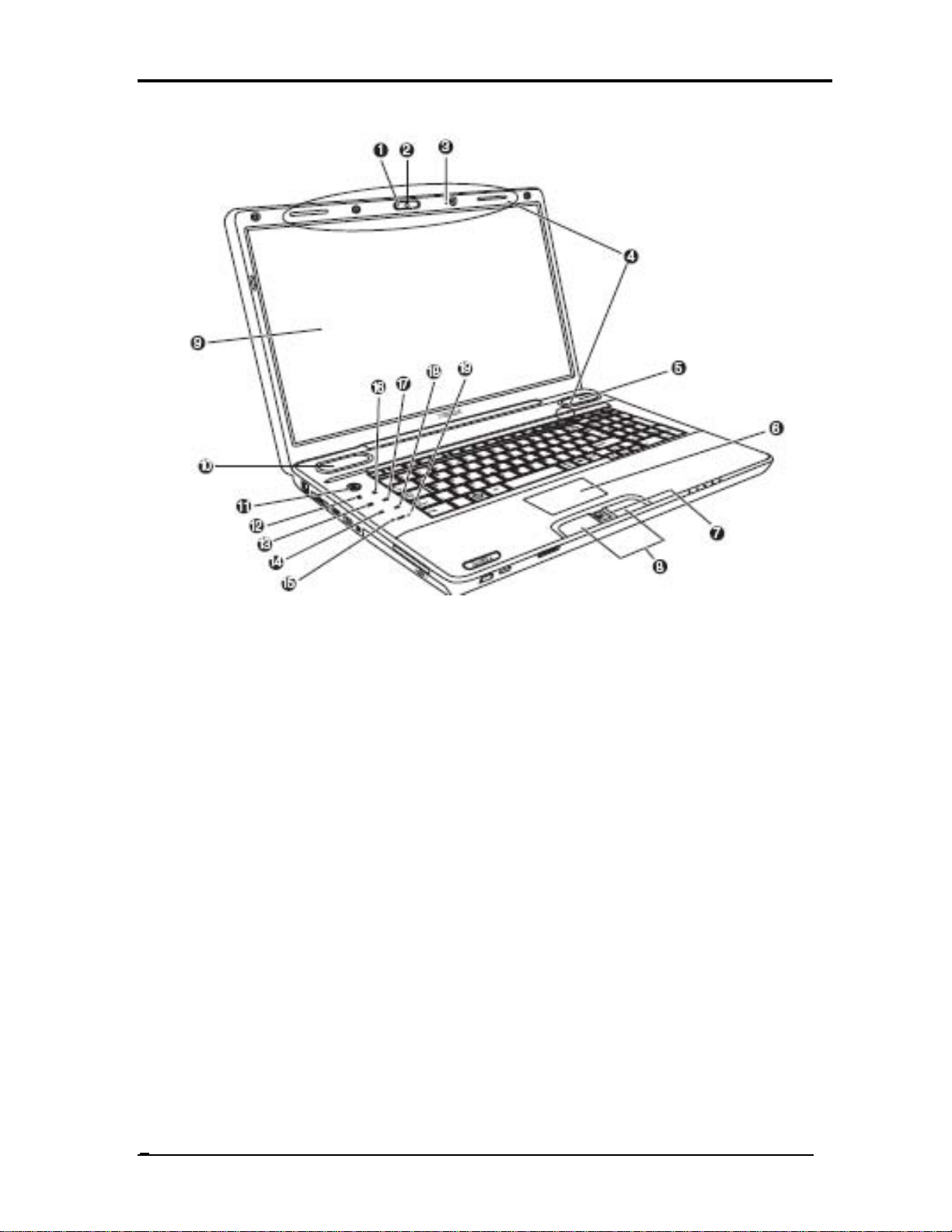
1. Web Camera LED* 2. Web Camera*
3. Built-in microphone* 4. Wireless LAN/Wireless WAN Antennas (Not shown)
5. Speaker 6. Touch Pad
7. Fingerprint Sensor* 8. Touch Pad Control Buttons
9. Display Screen 10. Speaker
11. Power Button* 12. Internet Button*
13. CD/ DVD Button* 14. Previous Button*
15. Volume Down Button* 16. Mute Button*
17. Play/Pause Button* 18. Next Button* 19. Volume Up Button*
Figure 1-1-1 Front of the computer
4
Qosmio X500 Maintenance Manual (960-Q08)
Page 21
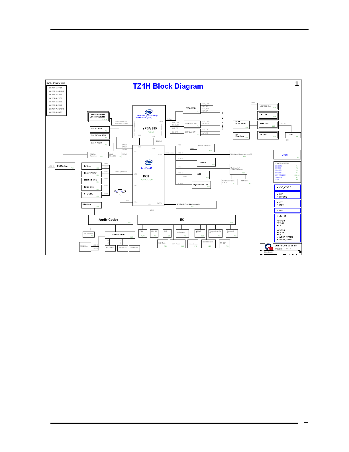
1.2 System Block Diagram
Figure 1-2-1 shows the system block diagram.
Chapter 1 Hardware Overview
Figure 1-2-1 System block diagram for Intel Platform
Qosmio X500 Maintenance Manual (960-Q08)
5
Page 22

Chapter 1 Hardware Overview
The PC contains the following components.
CPU
Intel® Core(TM) i7-720QM processor
1.6GHz, 1.73GHz
Memory
DDR3-1066MHz 1GB, 2GB or 4GB memory modules
200-pin SO-DIMM
1.8V operation
BIOS ROM (Flash memory)
16Mbit
Chipset
North Bridge
Penryn processor System Bus support
DRAM Controller : DDR3 1066MHz support
DMI
1299-ball 35 x 35mm Mirco FC-BGA Package
South Bridge
Direct Media Interface (DMI)
PCI Express
Serial ATA Controller
PCI Interface
Low Pin count (LPC) interface
Serial Peripheral Interface (SPI)
DMA controller
Advanced Programmable Interrupt Controller (APIC)
USB Controllers
Gigabit Ethernet Controller
RTC
GPIO
Enhanced Power Management
SMBus 2.0
High Definition Audio Controller
676-pin 31mmx31mm mBGA Package
6
Qosmio X500 Maintenance Manual (960-Q08)
Page 23

Chapter 1 Hardware Overview
Other main system chips
• Clock Generator
• EC/KBC –[W/CIR(Winbond WPCE775CA0DG)] –[WO/CIR(Winbond
WPCE775LA0DG)]
• HD Audio (CONEXANT CX20583-10Z)
• Card Reader controller (O2 OZ888GS0LN)
• 10/100 LAN controller (Atheros AR8132M)
• Giga LAN controller (Atheros AR8131M)
Mini Card
Wireless LAN (BTO)
DSSS/OFDM LAN card is equipped. Conformity with IEEE 802.11b/g, IEEE
802.11 a/g/n or IEEE 802.11a/b/g..
MODEM (Conexant x 1)
Supported by on board Modem + DAA daughter card.
Data and FAX transmission is available.
Supports ITU-TV.92.
The transfer speed of data receiving is 56kbps, of data sending is 33.6kbps and of
FAX is 14.4kbps. Actual speed depends on the quality of the line used.
Connected to telephone line through RJ11 MOD
Bluetooth
Bluetooth V2.1+EDR. (BTO)
Qosmio X500 Maintenance Manual (960-Q08)
7
Page 24
Chapter 1 Hardware Overview
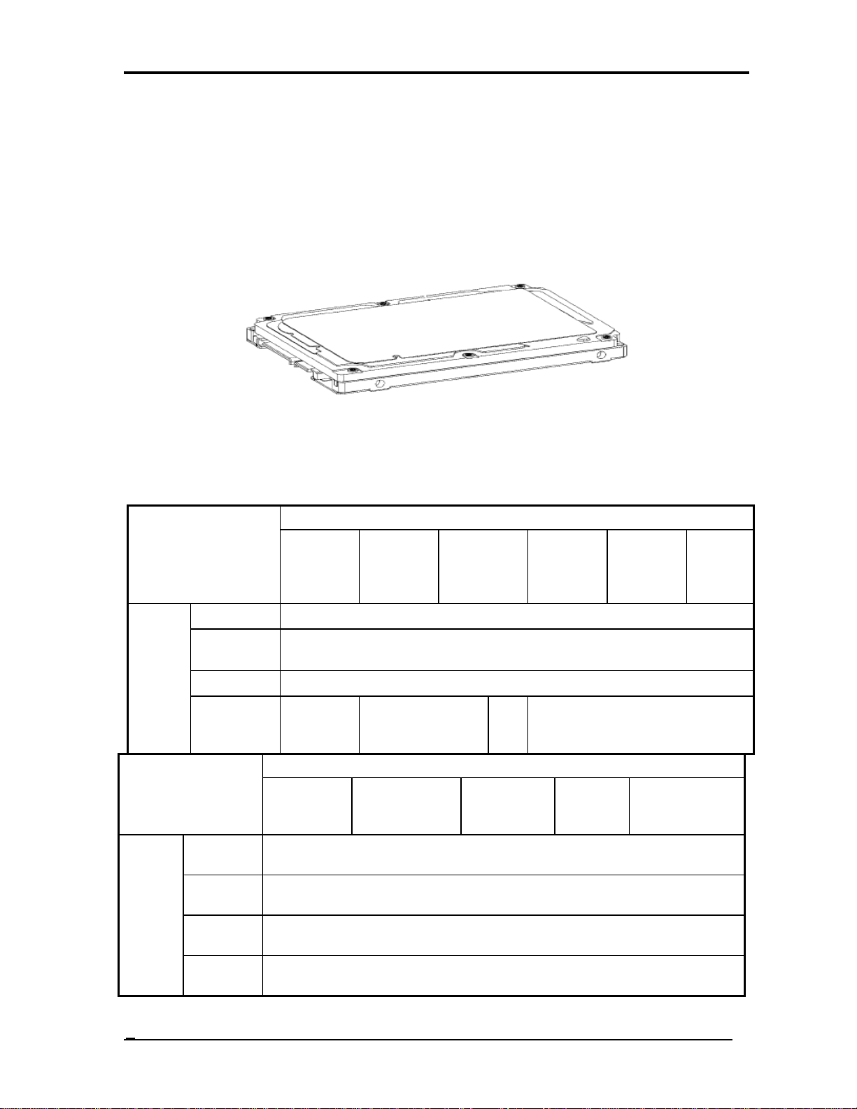
1.3 2.5-inch Hard Disk Drive
A compact, high-capacity HDD with a height of 9.5mm. Contains a 2.5-inch magnetic disk
and magnetic heads.
Figure 1-3-1 shows a view of the 2.5-inch HDD and Tables 1-3-2 and 1-3-3 list the
specifications.
Figure 1-3-1 2.5-inch HDD
Outline
dimens
ions
Outline
dimensi
ons
Parameter
Width (mm)
Height
(mm)
Depth (mm)
Weight (g)
Width
(mm)
Height
(mm)
Depth
(mm)
Weight
(g)
Table 1-3-2 2.5-inch HDD dimensions
Standard value
TOSHIBA
MK1655G
SX
TOSHIBA
MK2555G
SX
97/98 97/98
FUJITSU
MJA2160B
FUJITSU
MJA2250BH
H
TOSHIBA
MK3255GS
X
69.85 +/- 0.25
100.2 +/- 0.25
Standard value Parameter
FUJITSU
MJA2320B
101(Max)
9.5
101
//10
2
H
100
9.5
70
TOSHIBA
MK4055G
SX
FUJITSU
MJA240
0BH
TOSHIBA
MK3263G
SX
101//102
FUJITSU
MJA2500BH
TOSHIB
A
MK5055
GSX
8
Qosmio X500 Maintenance Manual (960-Q08)
Page 25
Chapter 1 Hardware Overview
Standard value Parameter
Outlin
e
dimen
sions
Width (mm)
Height (mm)
Depth (mm)
Weight (g)
HITACHI
HTS545016B9A
300
HITACHI
HTS545025B9
A300
95 (max.) 95 (max.)
HITACHI
HITACHI
HTS545032
B9A300
HTS545040
B9A300
69.85 +/- 0.25
9.5
100.2 +/- 0.25
102 (max.) 102 (max.)
HITACHI
HTS545050B9A
300
Table 1-3-3 2.5-inch HDD specifications
Specification
TOSHIBA
MK4055G
SX
Parameter
TOSHIBA
MK1655GSX
TOSHIBA
MK2555GS
X
TOSHIBA
MK3255G
SX
Storage size (formatted) 160GB 250GB 320GB 400 GB 500GB
Speed (RPM) 5,400
Data transfer Rate
- To/From Media
- T0/From Host
363~952 typical
3Gbps (150MB/s)
TOSHIBA
MK5055G
SX
bus transfer rate (MB/s)
Average random seek time
(read) (ms)
3Gbps(150MB/s)
12
Power-on-to-ready (sec) 3.5(typ)/9.5(Max)
Qosmio X500 Maintenance Manual (960-Q08)
9
Page 26
Chapter 1 Hardware Overview
Specification
Parameter
Storage size
(formatted)
Speed (RPM) 5,400
Data transfer Rate
- To/From Media
- T0/From Host
bus transfer rate
(MB/s)
Average random
seek time (read)
(ms)
Power-on-to-ready
(sec)
FUJITSU
MJA2160BH
160GB 250GB 320GB 400GB 500GB
FUJITSU
MJA2250BH
FUJITSU
MJA2320BH
363~952 typical
3Gbps (150MB/s)
3Gbps(150MB/s)
12.0ms/14.0ms
4.0(typ9.5(Max)
FUJITSU
MJA2400BH
FUJITSU
MJA2500BH
Specification
Parameter
Storage size (formatted)
HITACHI
HTS545016B
9A300
160GB 250GB 320GB 400GB 500GB
HITACHI
HTS545025B9
A300
HITACHI
HTS545032
B9A300
Speed (RPM) 5,400
Data transfer Rate
- To/From Media
- T0/From Host
bus transfer rate (MB/s)
Average random seek time
875MB/s Max.
875MB/s Max.
3Gbps
3Gbps
11
(read) (ms)
Power-on-to-ready (sec) 3.5 sec
HITACHI
HTS545040
B9A300
HITACHI
HTS545050B9A
300
10
Qosmio X500 Maintenance Manual (960-Q08)
Page 27
Chapter 1 Hardware Overview
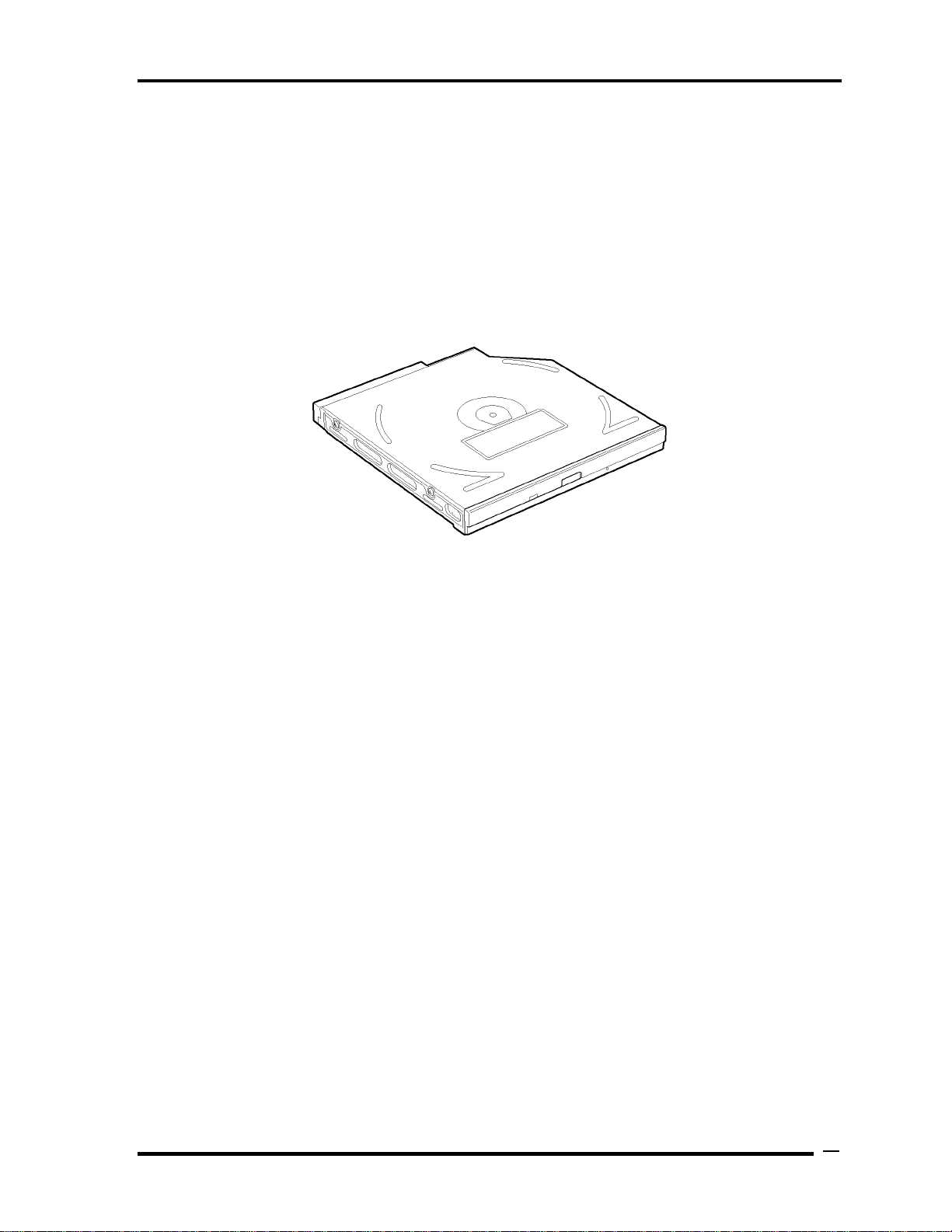
1.4 Optical Drive (HD DVD-ROM & CD-R/RW Drive)
The DVD Super Multi drive accommodates either 12 cm (4.72-inch) or 8 cm (3.15-inch)
CD/DVD-ROM, CD-R/RW, DVD±R/±RW and DVD-RAM. It is a high-performance drive
that reads DVD-ROM at maximum 8-speed and CD at maximum 24-speed. Write speed of
DVD±R/±RW and DVD-RAM is different depending on the drive.
The DVD Super Multi drive is shown in Figure 1-4-1. The dimensions and specifications of
the DVD Super Multi drive are described in Table 1-4-2, Table 1-4-3, Table 1-4-4, Table 14-5.
Figure 1-4-1 DVD Super Multi drive
Qosmio X500 Maintenance Manual (960-Q08)
11
Page 28
Chapter 1 Hardware Overview
Parameter Standard value
Outline
dimensions
Parameter Standard value
Outline
dimensions
Table 1-
Maker
Width (mm) 128
Height (mm) 12.7
Depth (mm) 127
Mass (g) 168
Maker
Width (mm) 128
Height (mm) 12.7
Depth (mm) 129
4-2
DVD Super Multi drive outline dimensions
HLDS
(GT20N-ATAK7N7 )
Panasonic
(UJ240/J890ADTJR-A)
HLDS
(GT20F-ATAK7N7)
Panasonic
(UJ141/UJ890EDTJR-A)
Parameter Standard value
Outline
dimensions
Mass (g) 185
Maker
Width (mm) 128
Height (mm) 12.7
Depth (mm) 127
Mass (g) 165
TSST
(TS-L633C)
TSST
(TS-L633Y)
12
Qosmio X500 Maintenance Manual (960-Q08)
Page 29
Chapter 1 Hardware Overview
Table 1-
Parameter
Label Flash Function
Data transfer
speed
Transfer
4-3
Read
Write
Burst
mode
HLDS DVD Super Multi drive specifications
HLDS Drive Specification
GT20N-ATAK7N7 GT20F-ATAK7N7
No support Support
DVD-ROM 8x max.
DVD-R(SL/DL) 8x/4x max.
DVD+R(SL/DL) 8x/4x max.
DVD-RW 8x max.
DVD+RW 8x max.
DVD-RAM (Ver.1.0) 2x
(Ver.2.2) 2x, 3x, 5x
DVD-Video 4x max. (Single/Dual layer)
CD-R/RW/ROM 24x/24x/24x max.
CD-DA (DAE: Ripping/Play) 20x/20x max.
DVD-R 2x CLV, 4x ZCLV, 8x CAV
DVD-R DL 2x CLV, 4x ZCLV
DVD-RW 1x, 2x CLV, 4x, 6x ZCLV
DVD-RAM 2x, 3x ZCLV, 5x PCAV(Ver.2.2)
(16x Media: Not support)
DVD+R 2.4x CLV, 4x ZCLV, 8x CAV
DVD+R DL 2.4x CLV, 4x ZCLV
DVD+RW .4x, 3.3x CLV, 4x ZCLV, 8x ZCLV
(8x Speed disc: 3.3x CLV, 8x ZCLV)
CD-R 10x CLV, 16x, 24x ZCLV
CD-RW 4x, 10x CLV, 16x ZCLV
PIO mode4/Multi word mode2/Ultra DMA mode2
Access time
(ms) (Random)
Buffer memory 2MB
CD-ROM 130ms (Typ.)
DVD-ROM 135ms (Typ.)
Qosmio X500 Maintenance Manual (960-Q08)
13
Page 30
Chapter 1 Hardware Overview
Table 1-
Parameter
Label Flash Function
Data transfer
speed
4-4
Panasonic DVD Super Multi drive specifications
Read
Write
Burst Transfer
mode
Panasonic Drive Specification
UJ240/UJ890ADTJR-A UJ141/UJ890EDTJR-A
No support Support
DVD-ROM :Max 8X CAV
CD-ROM :Max 24X CAV
CD-R :Max24X CAV
CD-RW :4X CLV
High Speed CD-RW :10XCLV
Ultra Speed CD-RW :Max 16X Zone CLV
DVD-R :Max.8X CAV
DVD-R DL :Max.4X Zone CLV
DVD-RW :Max.6X Zone CLV
DVD+R :Max.8X CAV
DVD+R DL :Max.4X Zone CLV
DVD+RW :Max.8X Zone CLV
DVD-RAM :3-5X ZCLV ( 4.7GB)
PIO mode4/Multi word mode2/Ultra DMA mode2
Access time
(ms) (Random)
Buffer memory 2MB
CD-ROM 150ms (Typ.)
DVD-ROM 180ms (Typ.)
14
Qosmio X500 Maintenance Manual (960-Q08)
Page 31

Chapter 1 Hardware Overview
Table 1-
4-5
TSST DVD Super Multi drive specifications
Qosmio X500 Maintenance Manual (960-Q08)
15
Page 32

Chapter 1 Hardware Overview
1.5 Keyboard
The Qosmio X500 keyboard has two different kinds of placement, one is for US style and the
other is for UK style.
Figure 1-5-1 is a view of the keyboard for US style
Figure 1-5-1 Keyboard for US style
Figure 1-5-2 is a view of the keyboard for UK style
Figure 1-5-2 Keyboard for UK style
See Appendix E for details of the keyboard layout
16
Qosmio X500 Maintenance Manual (960-Q08)
Page 33

Chapter 1 Hardware Overview
1.6 TFT Color Display
The Qosmio X500 Ganel use CCFL to control backlight.
1.6.1 LCD Module with CCFL Backlight
Figure 1-6-1 shows a view of the LCD module and Table 1-6-2 lists the specifications.
Figure 1-6-1 SAMSUNG LCD Module
Qosmio X500 Maintenance Manual (960-Q08)
17
Page 34

Chapter 1 Hardware Overview
Table 1-6-2 LCD module specifications
Specifications(WXGA+)
Item
Number of Pixel 1680 x 945 1920 x 1080
Dot spacing (mm)
Display Colors 262,144 colors 262,144 colors
Samsung
LTN184KT02-T01
0.243 (H)× 0.243 (V) 0.213 (H)× 0.213 (V)
Samsung
LTN184HT04-T01
18
Qosmio X500 Maintenance Manual (960-Q08)
Page 35
1.6.2 CCFL Inverter Board
Table 1-10 lists the FL inverter board specifications.
Table 1-6-3 FL inverter board specifications
Input
Output
Item
Voltage (V)
Power (W)
Voltage (Vrms)
Current
(f=55KHz)(mArms)
SUMIDA
TWS-449-341
8~21 8~21 8~21
7.5W 7.5W 7.5W
612~945 612~945 612~945
Chapter 1 Hardware Overview
Specifications
Ampower
T18I107.00
2.3±0.4 ~ 6.5±0.3
TDK
TBD573NR
Qosmio X500 Maintenance Manual (960-Q08)
19
Page 36

Chapter 1 Hardware Overview
1.7 Power Rails
Table 1-7-1 lists the power rail output specifications.
Table 1-7-1 Power supply output rating
Power supply (Yes/No)
Name
Voltage [V]
Power OFF
Suspend mode
Power OFF
Boot mode
No Main Battery (with RTC Battery)
+5VPCU
+5V
+3VPCU
+3V_S5
+3VSUS
+3V
+1.8VSUS
+SMDDR_VTERM
+SMDDR_VREF
+1.8V
+1.5V
+1.2V
+1.05v
+NB_CORE
VCC_CORE
+VCCRTC
5
5 No No No
3.3
3.3
3.3
3.3 No No No
1.8
1.8
1.8
1.8 No No No
1.5 No No No
1.25 No No No
1.05 No No No
1.0~1.2 No No No
0.7~1.2 No No No
3.266
Yes Yes
Yes Yes
Yes
Yes
Yes
Yes
Yes
Yes Yes Yes
No No
No No
No No
No No
No No
No
No
20
Qosmio X500 Maintenance Manual (960-Q08)
Page 37

1.8 Batteries
The PC has the following two batteries.
Main battery
Real time clock (RTC) battery
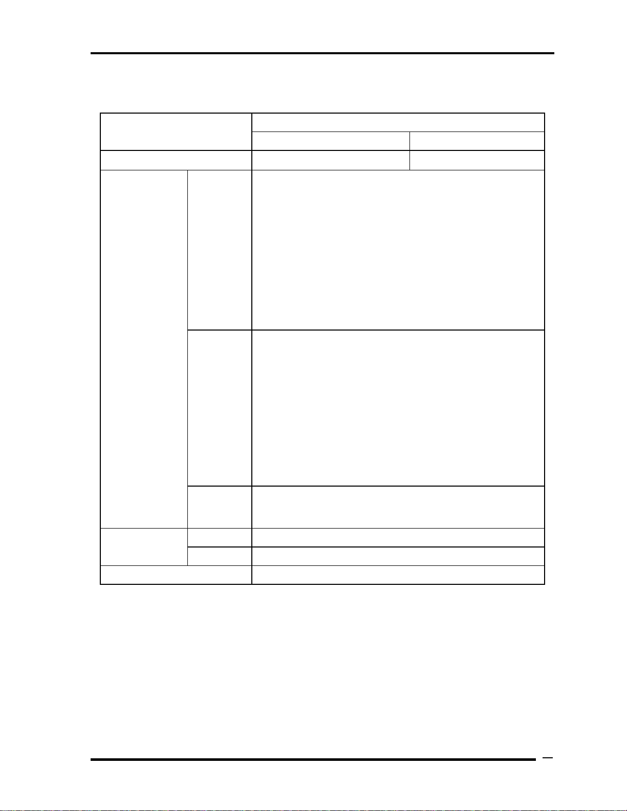
Table 1-8-1 lists the specifications for these two batteries.
Table 1-8-1 Battery specifications
Chapter 1 Hardware Overview
1.8.1 Main Battery
The main battery is the primary power supply for the computer when the AC adapter is not
connected.
Qosmio X500 Maintenance Manual (960-Q08)
21
Page 38

Chapter 1 Hardware Overview
1.8.2 Battery Charging Control
Battery charging is controlled by a power supply microprocessor. The power supply
microprocessor controls power supply and detects a full charge when the AC adaptor and
battery are connected to the computer.
Battery Charge
When the AC adapter is connected, normal charging is used while the system is
turned on and quick charge is used while the system is turned off. Refer to the
following Table 1-13.
Table 1-8-2 Time required for charges of main battery
Charge is stopped in the following cases.
1. The main battery is fully charged
2. The main battery is removed
3. Main battery or AC adapter voltage is abnormal
4. Charging current is abnormal
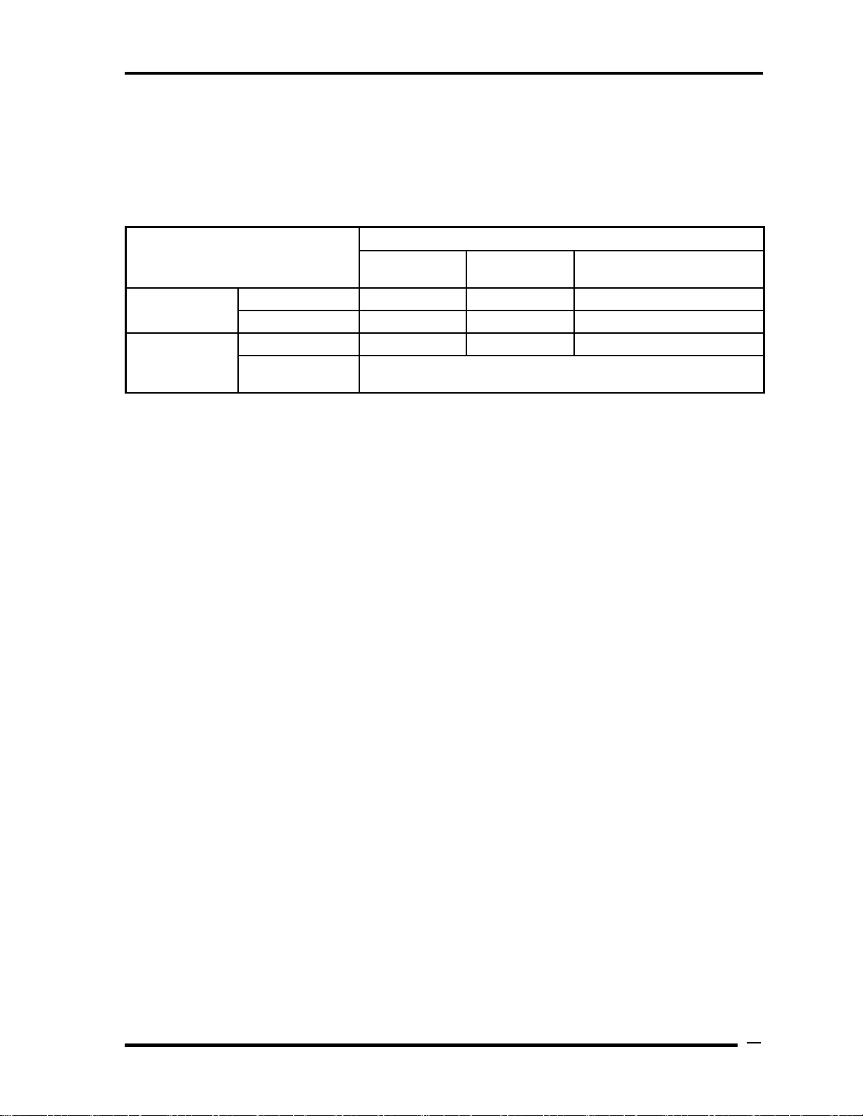
Data retaining time
When turning off the power in being charged fully, the retaining time is as following
Table 1-8-3.
22
Qosmio X500 Maintenance Manual (960-Q08)
Page 39

Chapter 1 Hardware Overview
Table 1-8-3 Data retaining time
* If USB Seep and Charge function is enabled, the computer’s battery will discharge during
hibernation or when the computer is turned off.
Qosmio X500 Maintenance Manual (960-Q08)
23
Page 40

Chapter 1 Hardware Overview
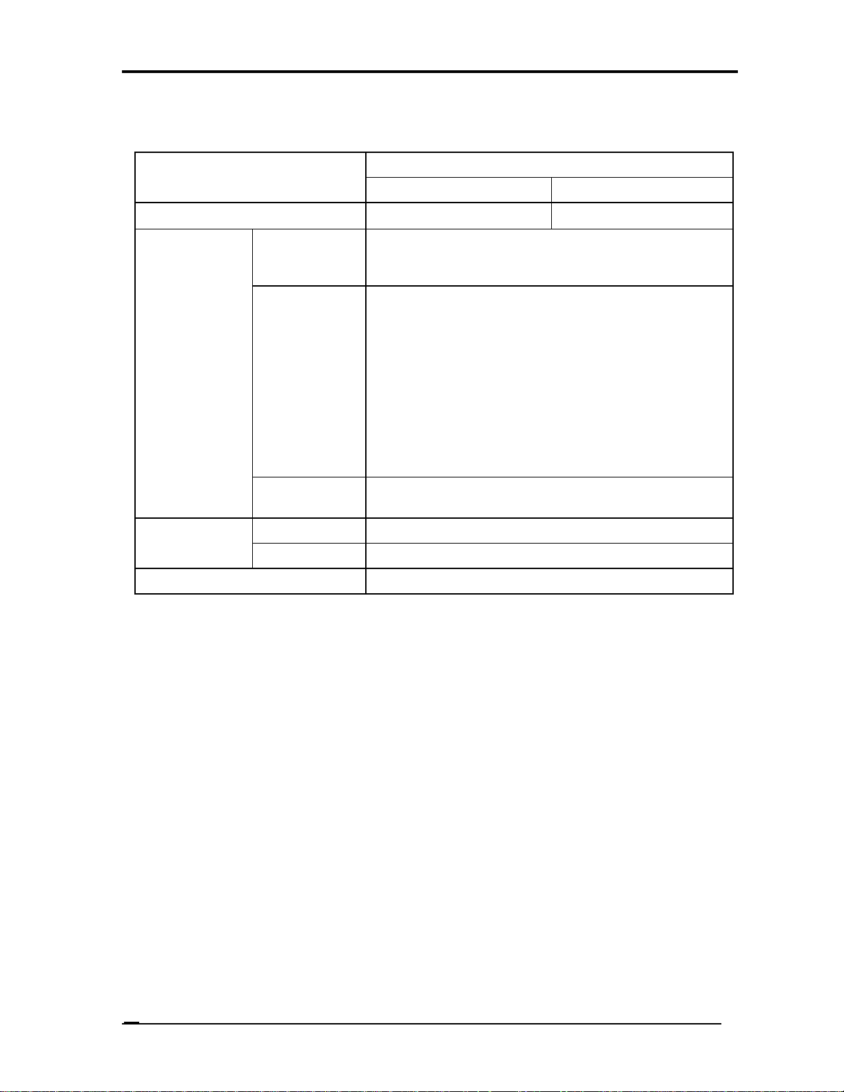
1.8.3 RTC Battery
The RTC battery provides the power supply to maintain the date, time, and other system
information in memory.
Table 1-8-4 lists the Time required for charges of RTC battery and data preservation time.
Table 1-8-4 Time required for charges of RTC battery
24
Qosmio X500 Maintenance Manual (960-Q08)
Page 41
1.9 AC Adapter
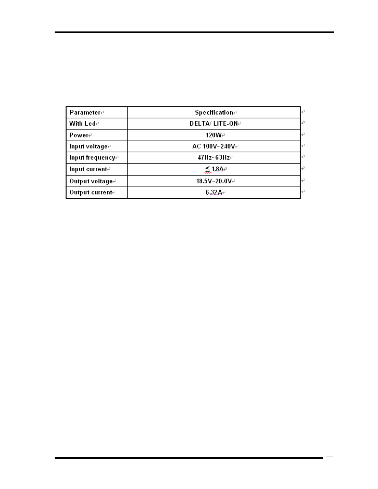
Table 1-9-1 lists the AC adapter specifications.
Table 1-9-1 AC adapter specifications
Chapter 1 Hardware Overview
Qosmio X500 Maintenance Manual (960-Q08)
25
Page 42

Chapter 2
Troubleshooting Procedures
2-1 Qosmio X500 Maintenance Manual (960-Q08)
Page 43

Chapter 2 Contents
2.1 Troubleshooting.............................................................................................................1
2.2 Troubleshooting Flowchart............................................................................................3
2.3 Power Supply Troubleshooting......................................................................................7
Procedure 1 Power Status Check ...................................................................7
Procedure 2 Connection Check......................................................................9
Procedure 3 Charging Check .......................................................................10
Procedure 4 Replacement Check ................................................................ 11
2.4 System Board Troubleshooting................................................................................... 12
Procedure 1 Message Check ....................................................................... 13
Procedure 2 Debugging Port Check............................................................ 14
Procedure 3 Replacement Check .................................................................14
2.5 USB FDD Troubleshooting .........................................................................................15
Procedure 1 FDD Head Cleaning Check .....................................................15
Procedure 2 Diagnostic Test Program Execution Check.............................16
Procedure 3 Connector Check and Replacement Check..............................17
2.6 2.5” HDD Troubleshooting..........................................................................................19
Procedure 1 Partition Check.........................................................................19
Procedure 2 Message Check ........................................................................20
Procedure 3 Format Check...........................................................................21
Procedure 4 Diagnostic Test Program Execution Check.............................22
Procedure 5 Connector Check and Replacement Check..............................23
2.7 Keyboard Troubleshooting ..........................................................................................24
Procedure 1 Diagnostic Test Program Execution Check.............................24
Procedure 2 Connector Check and Replacement Check..............................25
2.8 Touch pad Troubleshooting.........................................................................................26
Procedure 1 Diagnostic Test Program Execution Check.............................26
Procedure 2 Connector Check and Replacement Check..............................27
2-2 Qosmio X500 Maintenance Manual (960-Q08)
Page 44

2.9 Display Troubleshooting..............................................................................................28
Procedure 1 External Monitor Check...........................................................28
Procedure 2 Diagnostic Test Program Execution Check.............................28
Procedure 3 Connector and Cable Check.....................................................29
Procedure 4 Replacement Check .................................................................30
2.10 Optical Disk Drive Troubleshooting............................................................................31
Procedure 1 Diagnostic Test Program Execution Check.............................31
Procedure 2 Connector Check and Replacement Check..............................31
2.11 Modem Troubleshooting..............................................................................................32
Procedure 1 Diagnostic Test Program Execution Check.............................32
Procedure 2 Connector Check and Replacement Check..............................32
2.12 LAN Troubleshooting..................................................................................................34
Procedure 1 Diagnostic Test Program Execution Check.............................34
Procedure 2 Connector Check and Replacement Check..............................34
2.13 Wireless LAN Troubleshooting...................................................................................35
Procedure 1 Transmitting-Receiving Check................................................35
Procedure 2 Antennas' Connection Check...................................................36
Procedure 3 Replacement Check .................................................................37
2.14 Sound Troubleshooting................................................................................................38
Procedure 1 Connector Check......................................................................38
Procedure 2 Replacement Check .................................................................39
2.15 Fingerprint Troubleshooting........................................................................................40
Procedure 1 Diagnostic Test Program Execution Check.............................40
Procedure 2 Connector Check and Replacement Check.............................40
2.16 Bluetooth Troubleshooting ..........................................................................................41
Procedure 1 Connector Check and Replacement Check.............................41
Qosmio X500 Maintenance Manual (960-Q08) 2-3
Page 45

2 Troubleshooting Procedures
2
2.1 Troubleshooting
Chapter 2 describes how to determine which Field Replaceable Unit (FRU) in the computer
is causing the computer to malfunction.
The FRUs covered are:
1. Power supply 6. Touch pad 11. Wireless LAN
2. System Board 7. Display 12. Sound
3. USB FDD 8. Optical Disk Drive 13, Finger Print Board
4. 2.5” HDD 9. Modem 14, Bluetooth
5. Keyboard 10. LAN
The Test Program operations are described in Chapter 3. Detailed replacement procedures are
described in Chapter 4.
NOTE: After replacing the system board or CPU, it is necessary to execute the subtest 01
initial configuration of the 3.3 Setting of the hardware configuration in Chapter
3. Also update with the latest BIOS
After replacing the LCD, update with the latest EC/KBC.
The implement for the Diagnostics procedures is referred to Chapter 3. Also, following
implements are necessary:
1. Phillips screwdrivers (For replacement procedures)
2. Implements for debugging port check
Toshiba Free-DOS system FD
Qosmio X500 Maintenance Manual (960-Q08)
1
Page 46

2 Troubleshooting Procedures
There are following two types of connections in the figure of board and module connection in
and after 2.3 Power Supply Troubleshooting.
(1) Cable connection is described in the figure as line.
(2) Pin connection is described in the figure as arrow.
<e.g.> Connection of modem
Qosmio X500 Maintenance Manual (960-Q08)
2
Page 47

2 Troubleshooting Procedures
2.2 Troubleshooting Flowchart
Use the flowchart in Figure 2-1-1 as a guide for determining which troubleshooting
procedures to execute. Before going through the flowchart steps, verify the following:
Ask customer to enter the password if a password is registered.
Verify with the customer that Toshiba Windows is installed on the hard disk. Non-
Windows operating systems can cause the computer to malfunction.
Make sure all optional equipment is removed from the computer.
Qosmio X500 Maintenance Manual (960-Q08)
3
Page 48

2 Troubleshooting Procedures
Figure 2-1-1 Troubleshooting flowchart (1/2)
Qosmio X500 Maintenance Manual (960-Q08)
4
Page 49

2 Troubleshooting Procedures
Figure 2-1-2 Troubleshooting flowchart (2/2)
If the diagnostics program cannot detect an error, the problem may be intermittent. The Test
program should be executed several times to isolate the problem. Check the Log Utilities
Qosmio X500 Maintenance Manual (960-Q08)
5
Page 50

2 Troubleshooting Procedures
function to confirm which diagnostic test detected an error(s), and then perform the
appropriate troubleshooting procedures as follows:
1. If an error is detected on the system test, memory test, display test, CD-ROM/DVD-
ROM test, expansion test, real timer test, sound test or Modem/LAN/Bluetooth
/IEEE1394 test, perform the System Board Troubleshooting Procedures in Section 2.4.
2. If an error is detected on the floppy disk test, perform the USB FDD Troubleshooting
Procedures in Section 2.5.
3. If an error is detected on the hard disk test, perform the HDD Troubleshooting
Procedures in Section 2.6.
4. If an error is found on the keyboard test and pressed key display test, perform the
Keyboard Troubleshooting Procedures in Section 2.7.
5. If an error is found on the touch pad test, perform the touch pad Troubleshooting
Procedures in Section 2.8.
6. If an error is detected on the display test, perform the Display Troubleshooting
Procedures in Section 2.9.
7. If an error is detected on the CD-ROM/DVD-ROM test, perform the Optical Disk
Drive Troubleshooting Procedures in Section 2.10.
8. If an error is detected on the modem test, perform the Modem Troubleshooting
Procedures in Section 2.11.
9. If an error is detected on the LAN test, perform the LAN Troubleshooting Procedures
in Section 2.12.
10. If an error is detected on the wireless LAN test, perform the Wireless LAN
Troubleshooting Procedures in Section 2.13.
11. If an error is detected on the sound test, perform the Sound Troubleshooting
Procedures in Section 2.14.
12. If an error is detected on the fingerprint test, perform the fingerprint Troubleshooting
Procedures in Section 2.15.
13. If an error is detected on the Bluetooth test, perform the Bluetooth Troubleshooting
Procedures in Section 2.16.
Qosmio X500 Maintenance Manual (960-Q08)
6
Page 51

2 Troubleshooting Procedures
2.3 Power Supply Troubleshooting
The power supply controller controls many functions and components. To determine if the
power supply is functioning properly, start with Procedure 1 and continue with the other
Procedures as instructed. The procedures described in this section are:
Procedure 1: Power Status Check
Procedure 2: Connection Check
Procedure 3: Charging Check
Procedure 4: Replacement Check
Procedure 1 Power Status Check
The following LED indicates the power supply status:
Battery LED
DC IN LED
The Power Supply control displays the power supply status with the Battery LED and the DC
IN LED as listed in the tables below.
Table 2-1 Battery icon
Battery icon Power supply status
Lights orange
Lights red
Blinks orange
(even intervals)
Blinks orange once
(at being switched on)
Doesn’t light Any condition other than those above.
Battery is charged and the AC adapter is connected. It has
no relation with ON/OFF of the system power.
Battery is fully charged and the AC adapter is connected. It
has no relation with ON/OFF of the system power.
The battery level is low while the system power is ON.
The system is driven by only a battery and the battery level
is low.
Qosmio X500 Maintenance Manual (960-Q08)
7
Page 52

2 Troubleshooting Procedures
Table 2-2 DC IN icon
DC IN icon Power supply status
Lights red DC power is being supplied from the AC adapter.
Blinks orange Power supply malfunction*1
Doesn’t light Any condition other than those above.
*1 When the power supply controller detects a malfunction, the DC IN icon blinks orange.
When the icon is blinking, perform the following procedure.
1. Remove the battery pack and the AC adapter.
2. Re-attach the battery pack and the AC adapter.
If the icon is still blinking after the operation above, check the followings:
Check 1 If the DC IN icon blinks orange, go to Procedure 2.
Check 2 If the DC IN icon does not light, go to Procedure 3.
Check 3 If the battery icon does not light orange or green, go to Procedure 4.
NOTE: Use a supplied AC adapter.
Qosmio X500 Maintenance Manual (960-Q08)
8
Page 53

2 Troubleshooting Procedures
Procedure 2 Connection Check
The wiring diagram related to the power supply is shown below:
Any of the connectors may be disconnected. Perform Check 1.
Check 1 Make sure the AC adapter and the AC power cord is firmly plugged into the DC
IN connector PCN3 and wall outlet. If these cables are connected firmly, go to
Check 2.
Check 2 Replace the AC adapter and the AC power cord with new ones.
If the DC IN icon does not light, go to Procedure 4.
If the battery icon does not light, go to Check 3.
Check 3 Make sure the main battery pack is installed in the computer correctly. If the
battery is properly installed and the battery icon still does not light, go to
Procedure 4.
Procedure 3 Charging Check
Check if the power supply controller charges the battery pack properly. Perform the
following procedures:
Check 1 Make sure the AC adapter is firmly plugged into the DC IN socket.
Check 2 Make sure the battery pack is properly installed. If it is properly installed, go to
Check 3.
Check 3 The battery pack may be completely discharged. Wait a few minutes to charge the
battery pack while connecting the battery pack and the AC adapter. If the battery
pack is still not charged, go to Check 4.
Check 4 The battery’s temperature is too high or low. Leave the battery for a while to
Qosmio X500 Maintenance Manual (960-Q08)
9
Page 54

2 Troubleshooting Procedures
adjust it in the right temperature. If the battery pack is still not charged, go to
Check 5.
Check 5 Replace the battery pack with a new one. If the battery pack is still not charged,
go to Procedure 4.
Qosmio X500 Maintenance Manual (960-Q08)
10
Page 55

2 Troubleshooting Procedures
Procedure 4 Replacement Check
The power is supplied to the system board by the AC adapter. If either the AC adapter or the
system board was damaged, perform the following Checks.
To disassemble the computer, follow the steps described in Chapter 4, Replacement
Procedures.
When AC adapter is connected;
Check 1 AC adapter may be faulty. Replace the AC adapter with a new one. If the problem
still occurs, perform Check 2.
Check 2 System board may be faulty. Replace the system board with a new one.
When AC adapter is not connected ;
(When driving with battery pack)
Check 1 Battery pack may be faulty. Replace it with a new one. If the problem still occurs,
perform Check 2.
Check 2 System board may be faulty. Replace it with a new one.
Qosmio X500 Maintenance Manual (960-Q08)
11
Page 56

2 Troubleshooting Procedures
2.4 System Board Troubleshooting
This section describes how to determine if the system board is malfunctioning or not. Start
with Procedure 1 and continue with the other procedures as instructed. The procedures
described in this section are:
Procedure 1: Message Check
Procedure 2: Diagnostic Test Program Execution Check
Procedure 3: Replacement Check
Qosmio X500 Maintenance Manual (960-Q08)
12
Page 57

2 Troubleshooting Procedures
Procedure 1 Message Check
When the power is turned on, the system performs the Power On Self Test (POST) installed
in the BIOS ROM. The POST tests each IC on the system board and initializes it.
If an error message is shown on the display, perform Check 1.
If there is no error message, go to Procedure 2.
If Free-DOS or Windows is properly loaded, go to Procedure 3.
Check 1 If one of the following error messages is displayed on the screen, press the F2 key
as the message instructs. These errors occur when the system configuration
preserved in the RTC memory (CMOS type memory) is not the same as the actual
configuration or when the data is lost.
If you press the F2 key as the message instructs, the SETUP screen appears to set
the system configuration. If error message (b) appears often when the power is
turned on, replace the RTC battery.
Qosmio X500 Maintenance Manual (960-Q08)
13
Page 58

2 Troubleshooting Procedures
Procedure 2 Diagnostic Test Program Execution Check
Execute the following tests from the Diagnostic Test Menu. These tests check the system
board. Refer to Chapter 3, Tests and Diagnostic, for more information on how to perform
these tests.
1. System test
2. Memory test
3. Keyboard test
4. Display test
5. Floppy Disk test
6. VGA test
7. VGA Memory test
8. Hard Disk test
9. CPU Temperature test
10. Main Battery test
11. BIOS test
12. CD-ROM/DVD-ROM test
13. System Status LED test
14. Wireless LAN test
15. LAN/Modem/Sound test
16. UUID test-DMI Information (Write DMI)
If an error is detected during these tests, go to Procedure 3.
Procedure 3 Replacement Check
System board may be faulty. Disassemble the computer following the steps described in
Chapter 4, Replacement Procedures and replace system board with a new one.
Qosmio X500 Maintenance Manual (960-Q08)
14
Page 59

2 Troubleshooting Procedures
2.5 USB FDD Troubleshooting
To check if the USB FDD is malfunctioning or not, follow the troubleshooting procedures
below as instructed.
Procedure 1: FDD Head Cleaning Check
Procedure 2: Diagnostic Test Program Execution Check
Procedure 3: Connector Check and Replacement Check
Procedure 1 FDD Head Cleaning Check
FDD head cleaning is one option available in the Diagnostic Program.
After connecting USB FDD, insert the Diagnostics Disk in the floppy disk drive. Turn on the
computer and run the test. And then clean the FDD heads using the cleaning kit. If the FDD
still does not function properly after cleaning, go to Procedure 2.
Detailed operation is given in Chapter 3, Tests and Diagnostics.
If the test program cannot be executed on the computer, go to Procedure 3.
Qosmio X500 Maintenance Manual (960-Q08)
15
Page 60

2 Troubleshooting Procedures
Procedure 2 Diagnostic Test Program Execution Check
Insert the Diagnostics Disk in the USB FDD, turn on the computer and run the test. Refer to
Chapter 3, Tests and Diagnostics, for more information about the diagnostics test procedures.
Make sure the floppy disk is formatted correctly and that the write protect tab is disabled.
Floppy disk drive test error codes and their status names are listed in Table 2-7. If any other
errors occur while executing the FDD diagnostics test, go to Check 1.
Table 2-7 FDD error code and status
Code Status
01h Bad command
02h Address mark not found
03h Write protected
04h Record not found
06h Media replaced
08h DMA overrun error
09h DMA boundary error
10h CRC error
20h FDC error
40h Seek error
60h FDD not drive
80h Time out error (Not ready)
EEh Write buffer error
FFh Data compare error
Check 1 If the following message is displayed, disable the write protect tab on the floppy
disk by sliding the write protect tab to “write enable”. If any other message
appears, perform Check 2.
Write protected
Check 2 Make sure the floppy disk is formatted correctly. If it is, go to Procedure 3.
Qosmio X500 Maintenance Manual (960-Q08)
16
Page 61

2 Troubleshooting Procedures
Procedure 3 Connector Check and Replacement Check
USB FDD is connected to USB port on system board and US board. US board is also
connected to system board by cable. The connection of cable and board may be defective.
Otherwise, they may be faulty. Disassemble the computer following the steps described in
Chapter 4, Replacement Procedures and perform the following checks.
USB FDD can be connected to the following 4 ports on system board.
Check 1 Make sure USB FDD is firmly connected to USB port. If the connection is loose,
connect firmly and repeat Procedure 2. If the problem still occurs, go to Check 2.
NOTE: When checking the connection, be sure to check it with care for the followings.
1. Cable can not be disconnected from the connector.
2. Cable is connected straight to the connector.
3. Cable is connected all the way seated in the connector.
4. Cable can not be broken.
Qosmio X500 Maintenance Manual (960-Q08)
17
Page 62

2 Troubleshooting Procedures
Check 2 USB FDD may be faulty. Replace it with a new one. If the problem still occurs,
perform Check 3.
Check 3 Connect USB FDD to each port embedded on system board.
If it does not work properly, perform Check 4.
Check 4 System board may be faulty. Replace it with a new one following the steps in
Chapter 4, Replacement Procedures.
Qosmio X500 Maintenance Manual (960-Q08)
18
Page 63

2 Troubleshooting Procedures
2.6 2.5” HDD Troubleshooting
To check if 2.5” HDD is malfunctioning or not, follow the troubleshooting procedures below
as instructed.
Procedure 1: Partition Check
Procedure 2: Message Check
Procedure 3: Format Check
Procedure 4: Diagnostic Test Program Execution Check
Procedure 5: Connector Check and Replacement Check
CAUTION: The contents of the hard disk will be erased when the 2.5” HDD
troubleshooting procedures are executed. Transfer the contents of the hard
disk to other storage drive(s). For the backup, refer to the User’s Manual.
Procedure 1 Partition Check
Insert the Toshiba Free-DOS system disk and start the computer. Perform the following
checks:
Check 1 Input C: and press Enter. If you cannot change to drive C, go to Check 2. If you
can change to drive C, go to Procedure 2.
Check 2 Input FDISK and press Enter. Choose Display Partition Information from the
FDISK menu. If drive C is listed in the Display Partition Information, go to Check
3. If drive C is not listed, return to the FDISK menu and choose the option to
create a DOS partition or a logical DOS drive on drive C. If the problem still
occurs, go to Procedure 2.
Check 3 If drive C is listed as active in the FDISK menu, go to Check 4. If drive C is not
listed as active, return to the FDISK menu and choose the option to set the active
partition for drive C. Then go to Procedure 2.
Check 4 Remove the system disk from the FDD and reboot the computer. If the problem
still occurs, go to Procedure 2. Otherwise, the 2.5” HDD is operating normally.
Qosmio X500 Maintenance Manual (960-Q08)
19
Page 64

2 Troubleshooting Procedures
Procedure 2 Message Check
When the power is turned on, the system performs the Initial Reliability Test (IRT) installed
in the BIOS ROM. When the test detects an error, an error message is displayed on the screen.
Make sure no floppy disk is in the FDD. Turn on the computer and check the message on the
screen. When an OS starts from the 2.5” HDD, go to Procedure 3. Otherwise, start with
Check 1 below and perform the other checks as instructed.
Check 1 If either of the following messages appears, go to Check 3. If the following
messages do not appear, perform Check 3.
Insert system disk in drive
Press any key when ready .....
or
Non-System disk or disk error
Replace and press any key when ready
Check 2 Using the SYS command of the Free-DOS, transfer the system to the 2.5” HDD.
If the system is not transferred, go to Procedure 3. Refer to the Free -DOS Manual
for detailed operation.
If the following message appears on the display, the system program has been
transferred to the HDD.
System Transferred
If an error message appears on the display, perform Check 3.
Check 3 2.5” HDD(s) and the connector(s) of system board may be defective (Refer to the
steps described in Chapter 4, Replacement Procedures for disassembling.). Insert
HDD(s) to the connector(s) firmly. If it is (or they are) firmly connected, go to
Procedure 3.
Qosmio X500 Maintenance Manual (960-Q08)
20
Page 65

2 Troubleshooting Procedures
Procedure 3 Format Check
The computer’s HDD is formatted using the Free-DOS FORMAT program or the physical
format program of the test program. To format the HDD, start with Check 1 below and
perform the other steps as required.
Refer to the Free-DOS Manual for the operation of Free-DOS. For the format by the test
program, refer to the Chapter 3.
Check 1 Format an 2.5” HDD using Free-DOS FORMAT command. Type as FORMAT
C:/S/U.
If 2.5” HDD can not be formatted, perform Check 2.
Check 2 Using the Free -DOS FDISK command, set the 2.5” HDD partition. If the
partition is not set, go to Check 3. If it is set, format 2.5” HDD using Free-DOS
FORMAT command.
Check 3 Using the Diagnostic Disk, format 2.5” HDD with a format option (physical
format). If HDD is formatted, set the 2.5” HDD partition using Free-DOS FDISK
command.
If you cannot format 2.5” HDD using the Tests and Diagnostic program, go to
Procedure 4.
Qosmio X500 Maintenance Manual (960-Q08)
21
Page 66

2 Troubleshooting Procedures
Procedure 4 Diagnostic Test Program Execution Check
The HDD test program is stored in the Diagnostics Disk. Perform all of the HDD tests in the
Hard Disk Drive Test. Refer to Chapter 3, Tests and Diagnostics, for more information about
the HDD test program.
If an error is detected during the HDD test, an error code and status will be displayed. The
error codes and statuses are described in Table 2-8. If an error code is not displayed but the
problem still occurs, go to Procedure 5.
Table 2-5-1 2.5” Hard disk drive error code and status
Qosmio X500 Maintenance Manual (960-Q08)
22
Page 67

2 Troubleshooting Procedures
Procedure 5 Connector Check and Replacement Check
HDD(s) is/are connected to the connector(s) on the system board. The connection of HDD(s)
and board may be defective. Otherwise, they may be faulty. Disassemble the computer
following instructions in Chapter 4, Replacement Procedures and perform the following
checks.
Check 1 Make sure HDD(s) is/are firmly connected to the connector(s) on the system
board.
If any of the connections are loose, reconnect firmly and repeat Procedure 1. If the
problem still occurs, go to Check 2.
Check 2 (One of) HDD(s) may be faulty. Replace it with a new one following the
instructions in Chapter 4, Replacement Procedures and check the operation. If the
problem still occurs, perform Check 3.
Check 3 System board may be faulty. Replace it with a new one following the instructions
in Chapter 4, Replacement Procedures.
Qosmio X500 Maintenance Manual (960-Q08)
23
Page 68

2 Troubleshooting Procedures
2.7 Keyboard Troubleshooting
To check if the computer’s keyboard is malfunctioning or not, follow the troubleshooting
procedures below as instructed.
Procedure 1: Diagnostic Test Program Execution Check
Procedure 2: Connector and Replacement Check
Procedure 1 Diagnostic Test Program Execution Check
Execute the Keyboard Test (DIAGNOSTIC TEST) and Pressed key display test in the
Diagnostic Program. Refer to Chapter 3, Tests and Diagnostics, for more information on how
to perform the test program.
If an error occurs, go to Procedure 2. If an error does not occur, keyboard is functioning
properly.
Qosmio X500 Maintenance Manual (960-Q08)
24
Page 69

2 Troubleshooting Procedures
Procedure 2 Connector and Replacement Check
The connection of cable and board may be defective. Otherwise, they may be faulty.
Disassemble the computer following the steps described in Chapter 4, Replacement
Procedures, and perform the following checks:
Check 1 Make sure keyboard cable is firmly connected to system board.
If the connection is loose, reconnect firmly and repeat Procedure 1. If the problem
still occurs, go to Check 2.
Check 2 Keyboard may be faulty. Replace it with a new one following the instructions in
Chapter 4, Replacement Procedures. If the problem still occurs, perform Check 3.
Check 3 System board may be faulty. Replace it with a new one following the instructions
in Chapter 4, Replacement Procedures.
Qosmio X500 Maintenance Manual (960-Q08)
25
Page 70

2 Troubleshooting Procedures
2.8 Touch pad Troubleshooting
To check if the computer’s touch pad is malfunctioning or not, follow the troubleshooting
procedures below as instructed.
Procedure 1: Diagnostic Test Program Execution Check
Procedure 2: Connector and Replacement Check
Procedure 1 Diagnostic Test Program Execution Check
Execute the Touch pad test in the Diagnostic Program. Refer to Chapter 3, Tests and
Diagnostics, for more information on how to perform the test program.
If an error occurs, go to Procedure 2. If an error does not occur, touch pad is functioning
properly.
Qosmio X500 Maintenance Manual (960-Q08)
26
Page 71

2 Troubleshooting Procedures
Procedure 2 Connector and Replacement Check
The connection of cable and board may be defective. Otherwise, they may be faulty.
Disassemble the computer following the steps described in Chapter 4, Replacement
Procedures, and perform the following checks:
Check 1 Make sure the cable is firmly connected to system board.
If the connection is loose, reconnect firmly and repeat Procedure 1. If the problem
still occurs, go to Check 2.
Check 2 Touch Pad or the cable may be faulty. Replace it with a new one following the
instructions in Chapter 4, Replacement Procedures. If the problem still occurs,
perform Check 3.
Check 3 System board may be faulty. Replace it with a new one following the instructions
in Chapter 4, Replacement Procedures
Qosmio X500 Maintenance Manual (960-Q08)
27
Page 72

Troubleshooting Procedures
2.9 Display Troubleshooting
To check if the computer’s display is malfunctioning or not, follow the troubleshooting
procedures below as instructed.
Procedure 1: External Monitor Check
Procedure 2: Diagnostic Test Program Execution Check
Procedure 3: Connector and Cable Check
Procedure 4: Replacement Check
Procedure 1 External Monitor Check
Connect an external monitor to the computer’s external monitor port, and then boot the
computer. The computer automatically detects the external monitor
when “Power on Display” setting is “Auto-Selected” (Default) in BIOS Setup Menu.
If this setting is “System LCD only”, external monitor cannot be displayed.
If the external monitor works correctly, the internal LCD may be faulty. Go to Procedure 3.
If the external monitor appears to have the same problem as the internal monitor, system
board may be faulty. Go to Procedure 2.
Procedure 2 Diagnostic Test Program Execution Check
The Display Test program is stored in Diagnostics disk. This program checks the display
controller on system board. Insert the Diagnostics disk in the USB FDD, turn on the computer
and run the test. Refer to Chapter 3, Tests and Diagnostics for details. If an error is detected,
go to Procedure 3.
Qosmio X500 Maintenance Manual (960-Q08)
28
Page 73

Troubleshooting Procedures
Procedure 3 Connector and Cable Check
LCD Module is connected to system board by an LCD/FL cable. FL inverter board is also
connected to system board by an LCD/FL cable. And, fluorescent lamp is connected to FL
inverter board by HV cable. Their cables may be disconnected from system board or FL
inverter board. Disassemble the computer following the steps described in Chapter 4,
Replacement Procedures.
If the connection is loose, reconnect firmly and restart the computer. If the problem still
occurs, go to Procedure 4.
Qosmio X500 Maintenance Manual (960-Q08)
29
Page 74

Troubleshooting Procedures
Procedure 4 Replacement Check
Fluorescent lamp, FL inverter, LCD module, HV cable and LCD/FL cable are connected to
display circuits. Any of these components may be faulty. Refer to Chapter 4, Replacement
Procedures, for instructions on how to disassemble the computer and then perform the
following checks:
If LED backlight does not light, perform Check 1.
If characters or graphics on the internal display are not displayed clearly, perform
Check 3.
If some screen functions do not operate properly, perform Check 3.
If LED backlight remains lit when the display is closed, perform Check 4.
Check 1 LCD/FL cable may be faulty. Replace FL/LCD cable with a new one following the
instructions in Chapter 4, Replacement Procedure and test the display again. If the
problem still occurs, perform Check 2.
Check2 FL inverter may be faulty. Replace FL inverter with a new one following the
instructions in Chapter 4, Replacement Procedure and test the display again. If the
problem still occurs, perform Check 3.
Check 3 LCD module may be faulty. Replace LCD module with a new one following the
instructions in Chapter 4, Replacement Procedure and test the display again. If the
problem still occurs, perform Check 4.
Check 4 System board may be faulty. Replace it with a new one following the instructions
in Chapter 4, Replacement Procedure.
Qosmio X500 Maintenance Manual (960-Q08)
30
Page 75

Troubleshooting Procedures
2.10 Optical Disk Drive Troubleshooting
To check if optical disk drive is malfunctioning or not, follow the troubleshooting procedures
below as instructed.
Procedure 1: Diagnostic Test Program Execution Check
Procedure 2: Connector Check and Replacement Check
Procedure 1 Diagnostic Test Program Execution Check
Execute the CD-ROM/DVD-ROM Test in the Diagnostic Program. Refer to Chapter 3, Tests
and Diagnostics for more information on how to perform the test program.
Prepare the tools before the test.
If any error is detected by the test, go to Procedure 2.
Procedure 2 Connector Check and Replacement Check
The connection of optical disk drive and system board may be defective. Otherwise, they may
be faulty. Disassemble the computer following the steps described in Chapter 4 and perform
the following checks:
Check 1 Make sure optical disk drive is firmly connected to the connector on system board.
If the connection is loose, reconnect it firmly and return to Procedure 2. If the
problem still occurs, perform Check 2.
Check 2 Optical disk drive may be faulty. Replace it with a new one following the steps in
Chapter 4. If the problem still occurs, perform Check 3.
Check 3 System board may be faulty. Replace it with new one following the instructions in
Chapter 4.
Qosmio X500 Maintenance Manual (960-Q08)
31
Page 76
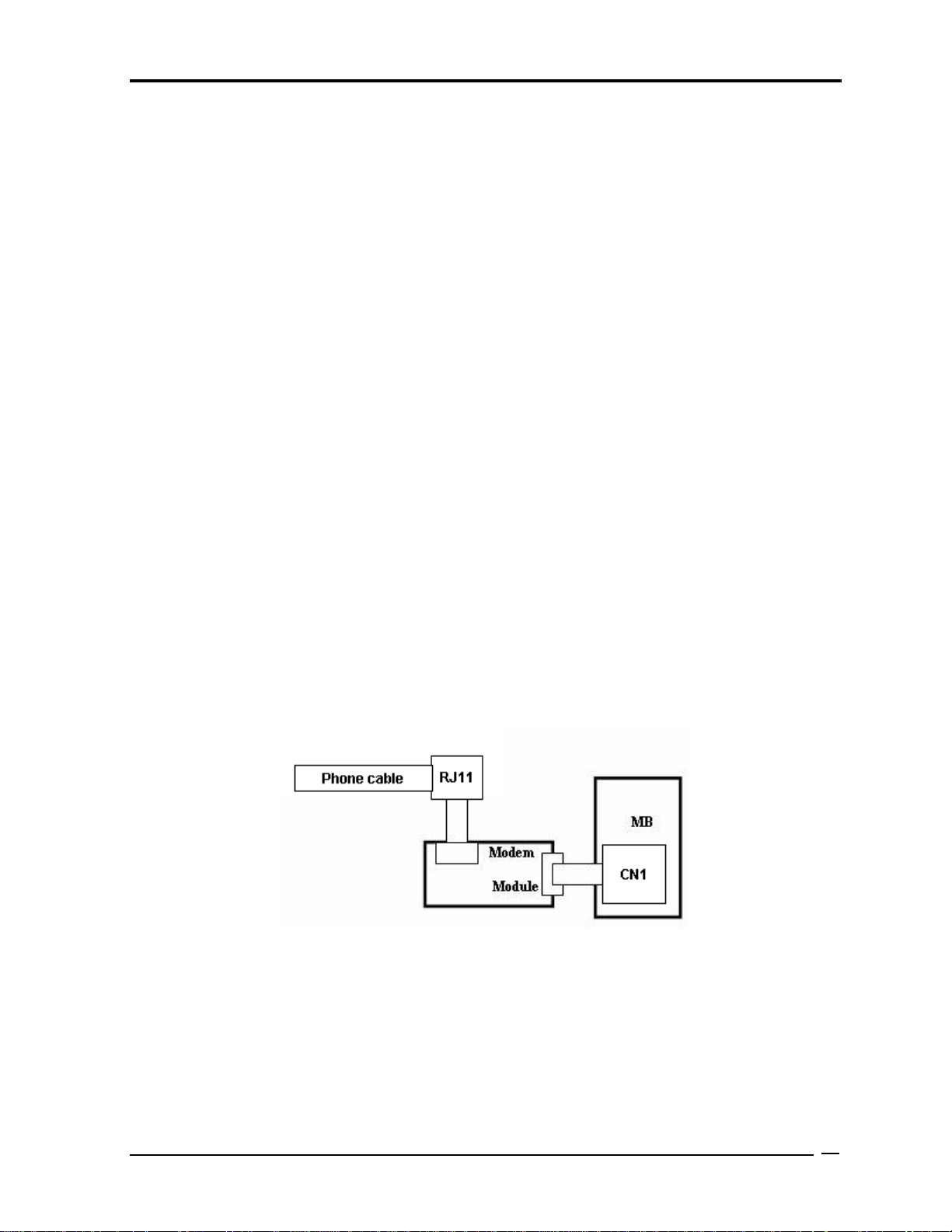
Troubleshooting Procedures
2.11 Modem Troubleshooting
To check if modem is malfunctioning or not, follow the troubleshooting procedures below as
instructed.
Procedure 1: Diagnostic Test Program Execution Check
Procedure 2: Connector Check and Replacement Check
Procedure 1 Diagnostic Test Program Execution Check
Execute Modem test in the LAN/Modem/Bluetooth/IEEE1394 test program. Refer to Chapter
3, Tests and Diagnostics for more information on how to perform the test program.
If any error is detected, perform Procedure 2.
Procedure 2 Connector Check and Replacement Check
MDC (Modem Daughter Card) is used as the modem for this computer. MDC is connected to
system board by connector. And also, MDC is connected to system and LAN board by modem
cable. If modem malfunctions, the connection of cable, board and module may be defective.
Otherwise, they may be faulty.
Disassemble the computer following the steps described in Chapter 4 and perform the
following checks:
Check 1 Make sure the following connections are firmly connected.
If any connector is disconnected, connect it firmly and return to Procedure 1. If the
problem still occurs, perform Check 2.
Qosmio X500 Maintenance Manual (960-Q08)
32
Page 77

Troubleshooting Procedures
Check 2 Modem cable may be faulty. Replace it with a new one. If the problem still occurs,
perform Check 3.
Check 3 MDC may be faulty. Replace it with a new one following the steps in Chapter 4. If
the problem still occurs, perform Check 4.
Check 4 Cable between MDC and system board may be faulty. Replace it with a new one
following the instructions in Chapter 4. If the problem still occurs, perform Check
5.
Check 5 System board may be faulty. Replace it with a new one following the instruction in
Chapter 4.
Qosmio X500 Maintenance Manual (960-Q08)
33
Page 78

Troubleshooting Procedures
2.12 LAN Troubleshooting
To check if the computer’s LAN is malfunctioning or not, follow the troubleshooting
procedures below as instructed.
Procedure 1: Diagnostic Test Program Execution Check
Procedure 2: Connector Check and Replacement Check
Procedure 1 Diagnostic Test Program Execution Check
Execute LAN test in the LAN/Modem test program. Refer to Chapter 3, Tests and Diagnostics
for more information on how to perform the test program.
If any error is detected by the test, go to Procedure 2.
Procedure 2 Connector Check and Replacement Check
The LAN function is embedded on system board. If LAN malfunctions, its connection is
defective or LAN cable and system board may be faulty.
Check 1 Make sure LAN cable is firmly connected to the connector CN1. If the problem
still occurs, perform Check 2.
Check 2 LAN cable may be faulty. Replace it with a new one. If the problem still occurs,
perform Check 3.
Check 3 System board may be faulty. Replace it with a new one following the instruction in
Chapter 4.
Qosmio X500 Maintenance Manual (960-Q08)
34
Page 79

Troubleshooting Procedures
2.13 Wireless LAN Troubleshooting
To check if the computer's Wireless LAN is malfunctioning or not, follow the troubleshooting
procedures below as instructed.
Procedure 1: Transmitting-Receiving Check
Procedure 2: Antennas' Connection Check
Procedure 3: Replacement Check
Procedure 1 Transmitting-Receiving Check
Before starting the test, make sure the
wireless communication is Enabled in BIOS setup
Check 1 Execute Wireless LAN test program to check the transmitting-receiving function
of wireless LAN. You will need a second computer that can communicate by
wireless LAN. Perform the test following the instructions described in Chapter 3.
If the computer passes the test, the function is correctly working. If the computer
does not pass the test, perform Procedure 2.
Qosmio X500 Maintenance Manual (960-Q08)
35
Page 80

Troubleshooting Procedures
Procedure 2 Antennas' Connection Check
The wireless LAN function-wiring diagram is shown below:
Any of the connections may be defective. Disassemble the computer following the steps
described in Chapter 4, Replacement Procedures, and perform the following checks:
Check 1 Make sure the wireless communication is Enabled in BIOS setup
If the Wireless communication is "Disabled", change it to "Enabled". If the
problem still occurs, perform Check 2.
Check 2 Make sure wireless LAN card is firmly connected to the CN15 on system board. If
the connector is defective, connect it firmly and perform Procedure 1. If the
problem still occurs, perform Check 3.
Check 3 Make sure that wireless LAN antenna cables (black and white) are firmly
connected to the connectors on Wireless LAN card. If wireless LAN antenna
cables are not connected properly, connect them firmly and perform Procedure 1.
If the problem still occurs, go to the procedure 3.
Qosmio X500 Maintenance Manual (960-Q08)
36
Page 81

Troubleshooting Procedures
Procedure 3 Replacement Check
Wireless LAN card, wireless LAN antenna or system board may be faulty. Refer to Chapter 4,
Replacement Procedures, for instructions on how to disassemble the computer and then
perform the following checks:
Check 1 Wireless LAN antenna may be faulty. Replace it with a new one following the
instructions in Chapter 4, Replacement Procedures. If the problem still occurs,
perform Check 2.
Check 2 Wireless LAN card may be faulty. Replace it with a new one following the
instructions in Chapter 4, Replacement Procedures. If the problem still occurs,
perform Check 3.
Check3 System board may be faulty. Replace it with a new one following the instructions
in Chapter 4, Replacement Procedures.
Qosmio X500 Maintenance Manual (960-Q08)
37
Page 82

Troubleshooting Procedures
2.14 Sound Troubleshooting
To check if the sound function is malfunctioning or not, follow the troubleshooting procedures
below as instructed.
Procedure 1: Connector Check
Procedure 2: Replacement Check
Procedure 1 Connector Check
The connection of sound system is shown in the following figure.
As the connection may be defective, disassemble the PC and check each connection.
If the problem still occurs, go to Procedure 2.
Qosmio X500 Maintenance Manual (960-Q08)
38
Page 83

Troubleshooting Procedures
Procedure 2 Replacement Check
If External microphone/Headphone does not work properly, perform check 1.
If Internal microphone /Speaker does not work properly, perform check 2.
If HP out does not work properly, perform check 3.
If Volume control does not work properly, perform check 4.
Check 1 External microphone/Headphone may be faulty. Replace it with a new one
following the steps in Chapter 4. If the problem still occurs, perform Check 5.
Check 2 Internal microphone /Speaker may be faulty. Replace it with a new one following
the steps in Chapter 4. If the problem still occurs, perform Check 5.
Check 3 HP out may be faulty. Replace it with a new one following the steps in Chapter 4.
If the problem still occurs, perform Check 5.
Check 4 Volume control may be faulty. Replace it with a new one following the steps in
Chapter 4. If the problem still occurs, perform Check 6.
Check 5 Flat cable between AD board/Speaker and system board may be faulty. Replace it
with new cable following the instructions in Chapter 4. If the problem still occurs,
perform Check 6.
Check 6 Audio board/System board may be faulty. Replace it with a new one following the
instructions in Chapter 4.
Qosmio X500 Maintenance Manual (960-Q08)
39
Page 84

Troubleshooting Procedures
2.15 Fingerprint Troubleshooting
To check if the computer’s Fingerprint is malfunctioning or not, follow the troubleshooting
procedures below as instructed.
Procedure 1: Connector Check and Replacement Check
Procedure 1 Diagnostic Test Program Execution Check
Execute Fingerprint test in the test program. Refer to Chapter 3, Tests and Diagnostics for
more information on how to perform the test program.
If any error is detected, perform Procedure 2.
Procedure 2 Connector Check and Replacement Check
The Fingerprint function is embedded on system board. If Fingerprint malfunctions, its
connection is defective or Fingerprint cable and system board may be faulty.
Check 1 Make sure Fingerprint cable is firmly connected to the connector. If the problem
still occurs, perform Check 2.
Check 2 Fingerprint cable may be faulty. Replace it with a new one. If the problem still
occurs, perform Check4.
Check 3 Fingerprint may be faulty. Replace it with a new one following the steps in
Chapter 4. If the problem still occurs, perform Check 4.
Check 4 System board may be faulty. Replace it with a new one following the instruction in
Chapter 4.
Qosmio X500 Maintenance Manual (960-Q08)
40
Page 85

Troubleshooting Procedures
2.16 Bluetooth Troubleshooting
To check if the computer’s Bluetooth is malfunctioning or not, follow the troubleshooting
procedure below as instructed.
Procedure 1: Connector Check and Replacement Check
Procedure 1 Connector Check and Replacement Check
The Bluetooth module is connected to system board. If Bluetooth malfunctions, its
connection is defective or Bluetooth cable and system board may be faulty.
Check 1 Make sure Bluetooth cable is firmly connected to the connector CN27. If the
problem still occurs, perform Check 2.
Check 2 Bluetooth cable may be faulty. Replace it with a new one. If the problem s till
occurs, perform Check 3.
Check 3 Bluetooth may be faulty. Replace it with a new one following the steps in Chapter
4. If the problem still occurs, perform Check 4.
Check 4 System board may be faulty. Replace it with a new one following the instruction in
Chapter 4.
Qosmio X500 Maintenance Manual (960-Q08)
41
Page 86

Test Program for Field.
Chapter 3
Diagnostic Programs
Qosmio X500
Maintenance Manual (960-Q08) 1
Page 87

Chapter 3 Contents
3.1 ............................................................3-3 Tests and Diagnostics Software Overview
3.2 ............................................................................... 3-4 Executing the Diagnostic Test
3.3 .........................................................................................................3-8 Subtest names
3.4 ..........................................................................................................3-11 System Test
3.5 ........................................................................................................3-18 Memory Test
3.6 ......................................................................................................3-22 Keyboard Test
3.7 ......................................................................................................... 3-25 Display Test
3.8 ..................................................................................................3-40 Floppy Disk Test
3.9 .....................................................................................................3-42 Hard Disk Test
3.10 ..........................................................................................3-45 Real Time Clock Test
3.11 .............................................................................................3-47 Cache Memory Test
3.12 ..............................................................................3-49 High Resolution Display Test
3.13 ...................................................................................................3-55 Multimedia Test
3.14 .................................................................................................. 3-56 MEMORY2 Test
3.15 ...................................................................3-58 Error Codes and Error Status Names
3.16 ........................................................................................................3-60 Running Test
3.17 .........................................................................................3-61 DMI INFOEMATION
3.17.1 ..............................................................................3-61 Check DMI Information
3.17.2 ................................................................................3-61 Write DMI Information
3.18 ......................................................................................................... 3-63 Log Utilities
3.18.1 ....................................................................................................3-63 Operations
3.19 ..........................................................................................3-65 System Configuration
3.20 ........................................................................................3-66 Running Test Edit Item
3.20.1 ....................................................................................3-66 Function Description
3.20.2 ..................................................................................3-66 Operation Description
3.21 .............................................................................3-68 Common Tests and Operation
3.21.1 ............................................................................3-68 How to operate a window
3.21.2 .....................................................................3-68 How to Stop the Test Program
3.21.3 ........................................................................................3-68 Test Status Screen
3.21.4 .........................................................................................3-70 Test Stop Display
3.21.5 .........................................................................................3-70 How to enter data
Test Program for Field.
2 Qosmio X500 Maintenance Manual (960-Q08)
Page 88

Test Program for Field.
3.1 Tests and Diagnostics Software Overview
This chapter explains how to use the Tests and Diagnostics Software for the Satellite P500
and Satellite Pro P500 computer systems.
NOTES: Before starting the Tests and Diagnostics software:
1. Check all cables for loose connections.
2. Exit any application and close Windows.
The Diagnostics Menu consists of the following options:
Diagnostic Test
Running Test
DMI Information
Log Utilities
System Configuration
Option
The Diagnostic Test Menu consists of the following functional tests:
System Test
Memory Test
Keyboard Test
Display Test
Floppy Disk Test
Hard Disk Test
Real Time Clock Test
Cache Memory Test
High Resolution Display Test
Multimedia Test
Memory2 Test
FDD & HDD Error Retry Count Set
The following equipment is required to perform some of the diagnostic test programs:
The Diagnostics Disk (all tests)
A formatted working disk for the floppy disk drive test (all tests)
A CD test media (Toshiba Backup CD ROM for the CD-ROM test)
The following sections detail the tests contained within the Diagnostic Test Menu. Refer to
Sections 3.18, 3.19, 3.20 and, 3.21 for detailed information on the remaining functions of the
Tests and Diagnostics software.
Qosmio X500
Maintenance Manual (960-Q08) 3
Page 89

Test Program for Field.
3.2 Executing the Diagnostic Test
DOS is required to run the Diagnostics Program. To start the programs follow these steps:
1. Create a DOS bootable disk and copy all the files from the Tests and Diagnostics
software to the disk.
2. Insert the boot disk into the computer’s floppy disk drive and turn on the computer.
NOTES: If error message display “Sorry. This Model Type Not Match This Machine”:
Please Check :
1. You test disk is match this model , ex. disk is 14” but machine is 13” .
2. The M/B EEPROM project type is math your test disk , if not , please use WDMI3.EXE
to modify with right LCD size .
The following screen displays:
TOSHIBA Satellite(Pro) P500 Diagnostics
Version v1.10
[ DIAGNOSTICS MENU ]
01.DIAGNOSTIC TEST
02.RUNNING TEST
03.DMI INFORMATION
04.LOG UTILITIES
05.SYSTEM CONFIGURATION
06.OPTION
99.EXIT
::Select item
ESC :Escape
3. To select the Diagnostic Test from the Diagnostics Menu use the arrow keys to set the
highlight bar to 01 and press Enter.
4 Qosmio X500 Maintenance Manual (960-Q08)
Page 90

Test Program for Field.
The following menu displays:
TOSHIBA Satellite(Pro) P500 Diagnostics
Version V1.10
[ DIAGNOSTICS MENU ]
01. DIAGNOSTIC TEST
02. RUNNING TEST
03. DMI INFORMATION
04. LOG UTILITIES
05. SYSTEM CONFIGURATION
01. SYSTEM TEST 08. CACHE MEMORY TEST
01. SYSTEM TEST
06. OPTION
02. MEMORY TEST 09. HIGH RESOLUTION DISPLAY TEST
99. EXIT
03. KEYBOARD TEST 10. MULTIMEDIA TEST
04. DISPLAY TEST 11. MEMORY2 TEST
05. FLOPPY DISK TEST 88. FDD&HDD ERROR RETRY COUNT SET
06. HARD DISK TEST 99. EXIT TO DIAGNOSTICS MENU
07. REAL TIME CLOCK TEST
[ DIAGNOSTIC TEST MENU ]
:Select item Enter:Decision item Esc:Escape
::Select item
ESC :Escape
Refer to Sections 3.4 through 3.14 for detailed descriptions of Diagnostics Tests 1 through
11. Item 88 sets the floppy disk drive and hard disk drive error retry count. Item 99 exits the
submenu of the Diagnostic Test and returns to the Diagnostics Menu.
Qosmio X500
Maintenance Manual (960-Q08) 5
Page 91

Test Program for Field.
01. SYS
4. Select the subtest you want to execute and press Enter. The following menu displays:
TOSHIBA Satellite(Pro) P500 Diagnostics
Version V1.10
: :Select item
ESC :Escape
[ DIAGNOSTICS MENU ]
01. DIAGNOSTIC TEST
02. RUNNING TEST
03. DMI INFORMATION
04. LOG UTILITIES
05. SYSTEM CONFIGURATION
01. SYSTEM TEST
01. SYSTEM TEST 9. REAL TIME CLOCK TEST
06. OPTION
02. MEMORY TEST 08. CACHE MEMORY TEST
99. EXIT
03. KEYBOARD TEST 09. HIGH RESOLUTION DISPLAY TEST
04. DISPLAY TEST 10. MULTIMEDIA TEST
05. FLOPPY DISK TEST 11. MEMRY2 TEST
06. HARD DISK TEST 88. FDD&HDD ERROR RETRY COUNT SET
07. REAL TIME CLOCK TEST 99. EXIT TO DIAGNOSTICS MENU
[ SYSTEM TEST ]
01. FAN ON/OFF
01. FAN ON/OFF
[ DIAGNOSTIC TEST MENU ]
02. Battery Test
03. CPU Temperature
99. Exit to DIAGNOSTIC TEST MENU
5. Select the desired test from the subtest menu and press Enter. The following Test
Parameter menu displays:
TOSHIBA Satellite(Pro) P500 Diagnostics
Version V1.10
: :Select item
ESC :Escape
[ DIAGNOSTICS MENU ]
01. DIAG STIC TEST NO
02. RUNNING TEST
03. DISK UTILITIES
4. LOG 0 UTILITIES
URATION05. SYST CONFIGEIM
01. SYSTEM TEST 09. REAL TIME CLOCK TEST
06. OPT ON
02. MEMORY TEST 10. NPX TEST
99. EXIT
03. KEYBOARD TEST 11. HIGH RESOLUTION DISPLAY TEST
04. DISPLAY TEST 12. MULTIMEDIA TEST
05. FLOPPY DISK TEST 13. USB TEST
06. HARD DISK TEST 14. MEMORY2 TEST
07. REAL TIME CLOCK TEST 88. FDD&HDD ERROR RETRY COUNT SET
99. EXIT TO DIAGNOSTICS MENU
[ TEST PARAMETER ]
01. Go To Test
01. Go To Test
02. Test Loop : YES
03. Error Stop : NO
TEM TEST
[ DIAGNOSTIC TEST MENU ]
01. FAN ON/OFF
01. FAN ON/OFF
02. Batterey Test
03. CPU T
99. Exit
[ SYSTEM TEST ]
mperature
to DIAGNOSTIC TEST MENU
Use the arrow keys to highlight the desired option and press Enter.
6 Qosmio X500 Maintenance Manual (960-Q08)
Page 92

Test Program for Field.
NOTES: The Item2 and 3 of Test Parameter are not used by some tests.
Go To Test
Move the highlight bar to Go To Test and press Enter to start executing the test.
Test Loop
Select NO to return the screen to the subtest menu after the test is complete.
Select YES to set the test to run continuously until it is halted by the user.
Error Stop
Select NO to keep the test running even if an error is found.
Select YES to stop the test program when an error is found and display the HALT
OPERATION screen as shown below:
[[ HALT OPERATION ]]
1: Test end
2: Continue
3: Retry
These three selections have the following functions:
1: Terminates the test program and exits to the subtest menu.
2: Continues the test from the error.
3: Restarts the test from the beginning.
Use the arrow keys to move the cursor to the desired option and press Enter.
Table 3-1 in Section 3.3 lists the function of each test on the subtest menu. Table 3-2 in
Section 3.15 lists the error codes and error status for each error.
Qosmio X500
Maintenance Manual (960-Q08) 7
Page 93

Test Program for Field.
3.3 Subtest names
Table 3-1 lists the subtest names for each test program in the Diagnostic
Test menu.
Table 3-1 Subtest Names(1/3)
No. Test Name No. Subtest Name
01 SYSTEM TEST 01
02
03
04
02 MEMORY TEST 01
02
03
04
05
03 KEYBOARD TEST 01
02
03
04
05
06
04 DISPLAY TEST 01
02
FAN ON/OFF check
Battery TEST
CPU Temperature
3D HDD Protection Test (90d)
Conventional Memory
Protected Mode
Protected Mode (32MB-MAX)
RAM Refresh
Stress Test
Pressed Key Display [109 KBD]
Pressed Key Display [105 KBD]
Pressed Key Display [104 KBD]
Hot Key Display [9 KBD]
Hot Key Display [1 KBD]
PS/2 Mouse (Pointing 2Button)
Character Attributes
Character Set
03
04
05
06
07
08
09
10
11
12
80* 25 Character Display
320* 200 Graphics Display
640* 200 Graphics Display
640* 480 Graphics Display
Display Page
“H” Pattern Display
Video DAC Register W/R/C
Color Graphics Display
Color Attributes Display
Color Tiling
8 Qosmio X500 Maintenance Manual (960-Q08)
Page 94

Test Program for Field.
No. Test Name No. Subtest Name
Table 3-1 Subtest Names(2/3)
05 FLOPPY DISK TEST 01
02
03
04
05
06 HARD DISK TEST 01
02
03
04
05
06
07
08
07 REAL TIME CLOCK
TEST
08 CACHE MEMORY
TEST
01
02
03
01
02
03
Sequential Read
Sequential W/R/C
Random Address/Data
Write Specified Address
Read Specified Address
Sequential Read
Address Uniqueness
Random Address Data
Cross Talk and Peek Shift
Write Specified Address
Read Specified Address
Sequential Write
W-R-C Specified Address
Real Time Test
Backup Memory Test
Real Time Carry Test
Constant Data Test
Address Pattern Test
Increment/Decrement Test
09 HIGH RESOLUTION
DISPLAY TEST
Qosmio X500
Maintenance Manual (960-Q08) 9
04
05
06
07
08
01
02
03
04
05
06
Bit Shift Pattern Test
*Write Disturb Test
Checker Board Test
Marching Test
Working Data Test
VRAM W/R/C Test
640* 480 Mode Display
800* 600 Mode Display
1024* 768 Mode Display
“H” Pattern Display
Focus Test (“E” Pattern)
Page 95

Test Program for Field.
Table 3-1 Subtest Names(3/3)
No. Test Name No. Subtest Name
10 MULTIMEDIA TEST 01
02
03
04
11 MEMORY2 01
02
03
04
*This test cannot support.
Sequential Read Test
Random Read Test
Read Specified Address Test
1 point W/R/C Test
All one/zero Test
Walking 1/Walking 0 Test(Left)
Walking 1/Walking 0 Test(Right)
Walking 1/Walking 0 Test(Left /Right)
10 Qosmio X500 Maintenance Manual (960-Q08)
Page 96

Test Program for Field.
3.4 System Test
To execute the System Test select 01 from the Diagnostic Test Menu, press Enter and follow
the directions on the screen. The System Test contains three subtests. Move the highlight bar
to the subtest you want to execute and press Enter.
Subtest 01 FAN ON/OFF Checking
Select 1,2,3 to control FAN on/off , 1=Fan on , 2=Fan off , 3=Exit .
[BOIFAN2.EXE] Program Version : 1.0
1: Fan On 2: Fan Off 3: Exit
Fan1 Status On Fan1RPM : 5000 or Fan1 Status OFF Fan1RPM : 0
Fan2 Status On Fan2RPM : 2500 or Fan2 Status OFF Fan2RPM : 0
Subtest 02 Battery Test
This will display battery information for check , press [ESC] to exit .
[BOIPCU.EXE] Program Version : 1.0 03-27-2007
voltage : 12522 mV Remaining capacity alarm : 400 mAh
temperature : 24.4 ‘C Remaining time alarm : 10 min
current : 1330 mA Battery mode : 0
average current : 1327 mA AtRate : 0 mA
relative state of charge : 93 % At rate time to full : 65535 min
absolute state of charge : 89 % At rate time to empty : 65535 min
remaining capacity : 3546 mAh At rate O. K. : FFFF
full charge capacity : 3800 mAh Maximun error : 2 %
run time to empty : -1 min. Charging current : 2800 mA
average time to empty : -1 min. Charging voltage : 12600 mA
average time to full : 101 min. Manufacturer name : SANYO
cycle count : 10 times Device name : NS2P3SZDNVWR
design capacity : 4000 mAh Device chemistry : LION
design voltage : 11100 mV Manufacturer data : 0
specification information : 2.1 Manufacture date : 9/13/2005
serial no. : 32009
STATUS : INIT
Press [ESC] KEY to exit
Qosmio X500
Maintenance Manual (960-Q08) 11
Page 97

Test Program for Field.
Subtest 03 CPU Temperature
This will display CPU Temperature for check , press [ESC] to exit .
[CPU_TEMP.EXE] Program Version : 1.3 03-09-2009
CPU Temperature : XX
GPU Temperature : XX
NOTES: If no external Graphics , GPU not report temperature .
Subtest 04 3D HDD Protection Test (90d)
1. For Field inspection T&D.
This program judges by sampling five kinds of data shown below.
No Item Contents
1 Access
An access platform is leveling.
platform.
The Fixture which fixes PC by 90 degree inclination is used. 2 Test Fixture
Vibration/shock doesn't take a PCB at the time of T&D inspection.
12 Qosmio X500 Maintenance Manual (960-Q08)
Page 98

Test Program for Field.
3 Test1
The display of a test program and the set method of PC are shown
below.
Display of a Test Program
The portion which PC and Test-Fixture contact is green.
Set method of PC
Z
Upper
X
Judgment
If all data is less than ranges, it will be OK.
Qosmio X500
Maintenance Manual (960-Q08) 13
Page 99

Test Program for Field.
r
4 Test2
The display of a test program and the set method of PC are shown
below.
Display of a Test Program
Set method of PC
Rear
Uppe
Judgment
If all data is less than ranges, it will be OK.
14 Qosmio X500 Maintenance Manual (960-Q08)
Page 100

Test Program for Field.
r
5 Test3
The display of a test program and the set method of PC are shown
below.
Display of a Test Program
Set method of PC
Right
Uppe
Judgment
If all data is less than ranges, it will be OK.
Qosmio X500
Maintenance Manual (960-Q08) 15
 Loading...