

Page 1

Toshiba Personal Computer
Satellite T110/Satellite ProT110/PORTEGE T110
Maintenance Manual
TOSHIBA CORPORATION
File Number 960-Q08
Satellite T110 / Satellite Pro T110 / PORTEGE T110 Maintenance Manual (960-Q08)
Page 2

Copyright
© 2009 by Toshiba Corporation. All rights reserved. Under the copyright laws, this manual
cannot be reproduced in any form without the prior written permission of Toshiba. No patent
liability is assumed with respect to the use of the information contained herein.
Toshiba Personal Computer Satellite T110, Satellite Pro T110, PORTEGE T110
Maintenance Manual
First edition Sept. 2009
Disclaimer
The information presented in this manual has been reviewed and validated for accuracy. The
included set of instructions and descriptions are accurate for the Satellite T110, Satellite Pro
T110, and PORTEGE T110 Series at the time of this manual's production. However,
succeeding computers and manuals are subject to change without notice. Therefore, Toshiba
assumes no liability for damages incurred directly or indirectly from errors, omissions, or
discrepancies between any succeeding product and this manual.
Trademarks
Intel, Intel SpeedStep, Intel Core, Pentium and Celeron are trademarks or registered
trademarks of Intel Corporation or its subsidiaries in the United States and other
countries/regions.
Windows and Microsoft are registered trademarks of Microsoft Corporation.
Other trademarks and registered trademarks not listed above may be used in this manual.
Satellite T110 / Satellite Pro T110 / PORTEGE T110 Maintenance Manual (960-Q08)
Page 3
Preface
This maintenance manual describes how to perform hardware service maintenance for the
Toshiba Personal Computer Satellite T110, Satellite Pro T110, and PORTEGE T110 Series.
The procedures described in this manual are intended to help service technicians isolate
faulty Field Replaceable Units (FRUs) and replace them in the field.
SAFETY PRECAUTIONS
Four types of messages are used in this m
anual to bring important information to your
attention. Each of these messages will be italicized and identified as shown below.
DANGER: “Danger” indicates the existence of a hazard that could result in death or
serious bodily injury, if the safety instruction is not observed.
WARNING: “Warning” indicates the existence of a hazard that could result in bodily
injury, if the safety instruction is not observed.
CAUTION: “Caution” indicates the existence of a hazard that could result in property
damage, if the safety instruction is not observed.
NOTE: “Note” contains general information that relates to your safe maintenance
service.
Improper repair of the computer may result in safety hazards. Toshiba requires service
technicians and authorized dealers or service providers to ensure the following safety
precautions are adhered to strictly.
Be sure to fasten screws securely with the right screwdriver. If a screw is not fully
fastened, it could come loose, creating a danger of a short circuit, which could cause
overheating, smoke or fire.
If you replace the battery pack or RTC battery, be sure to use only the same model
battery or an equivalent battery recommended by Toshiba. Installation of the wrong
battery can cause the battery to explode.
Satellite T110 / Satellite Pro T110 / PORTEGE T110 Maintenance Manual (960-Q08)
Page 4

The manual is divided into the following parts:
Chapter 1 Hardware Overview describes the Satellite T110, Satellite Pro T110,
PORTEGE T110 system unit and each FRU.
Chapter 2 Troubleshooting Procedures explains how to diagnose and resolve
FRU problems.
Chapter 3 Test and Diagnostics describes how to perform test and diagnostic
operations for maintenance service.
Chapter 4 Replacement Procedures describes the removal and replacement of the
FRUs.
Appendices The appendices describe the following:
Handling the LCD Module
Board layout
Pin assignments
Keyboard scan/character codes
Key layout
Wiring diagrams
Satellite T110 / Satellite Pro T110 / PORTEGE T110 Maintenance Manual (960-Q08)
Page 5

Conventions
This manual uses the following formats to describe, identify, and highlight terms and
operating procedures.
Acronyms
On the first appearance and whenever necessary for clarification acronyms are enclosed in
parentheses following their definition. For example:
Read Only Memory (ROM)
Keys
Keys are used in the text to describe many operations. The key top sym
bol as it appears on
the keyboard is printed in boldface type.
Key operation
Some
operations require you to simultaneously use two or more keys. We identify such
operations by the key top symbols separated by a plus (+) sign. For example, Ctrl + Pause
(Break) means you must hold down Ctrl and at the same time press Pause (Break). If
three keys are used, hold down the first two and at the same time press the third.
User input
Text that you are instructed to type in is shown in the boldface type below:
DISKCOPY A: B:
The display
Text generated by the computer that appears on its display is presented in the typeface
below:
at complete
Form
System transferred
Satellite T110 / Satellite Pro T110 / PORTEGE T110 Maintenance Manual (960-Q08)
Page 6

Table of Contents
Chapter 1 Hardware Overview
1.1 Features..........................................................................................................................1
1.2 System Block Diagram..................................................................................................6
1.3 2.5-inch Hard Disk Drive...............................................................................................9
1.4 Keyboard......................................................................................................................12
1.5 TFT Color Display.......................................................................................................13
1.5.1 LCD Module with CCFL Backlight .............................................................13
1.6 Power Rails..................................................................................................................14
1.7 Batteries .......................................................................................................................15
1.7.1 Main Battery .................................................................................................15
1.7.2 Battery Charging Control..............................................................................15
1.7.3 RTC battery...................................................................................................17
1.8 AC Adapter ..................................................................................................................18
Satellite T110 / Satellite Pro T110 / PORTEGE T110 Maintenance Manual (960-Q08)
Page 7

Chapter 2 Troubleshooting Procedures
2.1 Troubleshooting............................................................................................................1
2.2 Troubleshooting Flowchart........................................................................................... 2
2.3 Power Supply Troubleshooting..................................................................................... 6
Procedure 1 Power Status Check .................................................................................. 6
Procedure 2 Connection Check..................................................................................... 8
Procedure 3 Charging Check ........................................................................................ 8
Procedure 4 Replacement Check ................................................................................ 10
2.4 System Board Troubleshooting...................................................................................11
Procedure 1 Message Check .......................................................................................12
Procedure 2 Debugging Port Check............................................................................13
Procedure 3Replacement Check ................................................................................. 13
2.5 Hard Disk Drive Troubleshooting .............................................................................. 14
Procedure 1 Partition Check ....................................................................................... 14
Procedure 2 Message Check ....................................................................................... 15
Procedure 3 Diagnostic Test Program Execution Check............................................ 16
Procedure 4 Connector Check and Replacement Check............................................. 17
2.6 Keyboard Troubleshooting ......................................................................................... 18
Procedure 1 Diagnostic Test Program Execution Check............................................ 18
Procedure 2 Connector Check and Replacement Check............................................. 19
2.7 Touch pad Troubleshooting........................................................................................ 20
Procedure 1 Diagnostic Test Program Execution Check............................................ 20
Procedure 2 Connector Check and Replacement Check............................................. 21
2.8 Display Troubleshooting............................................................................................. 22
Procedure 1 External Monitor Check.......................................................................... 22
Procedure 2 Diagnostic Test Program Execution Check............................................ 22
Procedure 3 Connector and Cable Check ................................................................... 23
Procedure 4 Replacement Check ................................................................................ 24
2.9 LAN Troubleshooting................................................................................................. 25
Procedure 1 Diagnostic Test Program Execution Check............................................ 25
Satellite T110 / Satellite Pro T110 / PORTEGE T110 Maintenance Manual (960-Q08)
Page 8

Procedure 2 Connector Check and Replacement Check..............................................25
2.10 Wireless LAN Troubleshooting...................................................................................26
Procedure 1 Transmitting-Receiving Check................................................................26
Procedure 2 Antennas' Connection Check...................................................................27
Procedure 3 Replacement Check .................................................................................28
2.11 Sound Troubleshooting................................................................................................29
Procedure 1 Connector Check......................................................................................29
Procedure 2 Replacement Check .................................................................................30
2.12 Bluetooth Troubleshooting..........................................................................................31
Procedure 1 Connector Check and Replacement Check.............................................31
2.13 HDMI Troubleshooting ...............................................................................................32
Procedure 1 Connector Check and Replacement Check..............................................32
Procedure 2 External Monitor Check...........................................................................32
Procedure 3Connector and Cable Check .....................................................................33
Procedure 4Replacement Check ..................................................................................34
2.14 Memory Troubleshooting............................................................................................35
Procedure 1 Diagnostic Test Program Execution Check.............................................35
Procedure 2 Connect Check and Replacement Check.................................................35
2.15 3G Troubleshooting.....................................................................................................36
Procedure 1 Connect Check and Replacement Check.................................................36
2.16 Camera Troubleshooting..............................................................................................37
Procedure 1 Camera Execution Check.........................................................................37
Procedure 2 Connect Check and Replacement Check.................................................37
2.17 Microphone Troubleshooting ......................................................................................38
Procedure 1 Sound Recorder Execution Check...........................................................38
Procedure 2 Connect Check and Replacement Check.................................................38
2.18 CRT Troubleshooting ..................................................................................................39
Procedure 1 External Monitor Check...........................................................................39
Procedure 2 Connector and Cable Check ....................................................................39
Procedure 3 Replacement Check .................................................................................39
2.19 USB Troubleshooting ..................................................................................................40
Satellite T110 / Satellite Pro T110 / PORTEGE T110 Maintenance Manual (960-Q08)
Page 9

Procedure 1 Diagnostic Test Program Execution Check............................................ 40
Procedure 2 Connect Check and Replacement Check................................................ 40
2.20 LED Troubleshooting ................................................................................................. 41
Procedure 1 Each function Execution Check.............................................................. 41
Procedure 2 Connect Check and Replacement Check................................................ 41
Satellite T110 / Satellite Pro T110 / PORTEGE T110 Maintenance Manual (960-Q08)
Page 10

Chapter 3 Diagnostic Programs
3.1 Tests and Diagnostics Software Overview....................................................................2
3.2 Executing the Diagnostic Test.......................................................................................3
3.3 Subtest names.................................................................................................................7
3.4 System Test..................................................................................................................10
3.5 Memory Test................................................................................................................17
3.6 Keyboard Test..............................................................................................................21
3.7 Display Test.................................................................................................................24
3.8 Hard Disk Test.............................................................................................................39
3.9 Real Time Clock Test ..................................................................................................42
3.10 Cache Memory Test.....................................................................................................44
3.11 High Resolution Display Test......................................................................................46
3.12 Multimedia Test...........................................................................................................52
3.13 MEMORY2 Test..........................................................................................................53
3.14 Error Codes and Error Status Names...........................................................................55
3.15 Running Test................................................................................................................57
3.16 DMI INFOEMATION.................................................................................................58
3.16.1 Check DMI Information ...................................................................................58
3.16.2 Write DMI Information.....................................................................................58
3.17 Log Utilities.................................................................................................................60
3.17.1 Operations.........................................................................................................60
3.18 System Configuration ..................................................................................................62
3.19 Running Test Edit Item................................................................................................63
3.19.1 Function Description.........................................................................................63
3.19.2 Operation Description.......................................................................................63
3.20 Common Tests and Operation .....................................................................................65
3.20.1 How to operate a window.................................................................................65
3.20.2 How to Stop the Test Program..........................................................................65
3.20.3 Test Status Screen.............................................................................................65
3.20.4 Test Stop Display..............................................................................................66
3.20.5 How to enter data..............................................................................................66
Satellite T110 / Satellite Pro T110 / PORTEGE T110 Maintenance Manual (960-Q08)
Page 11

Chapter 4 Replacement Procedures
4.1 Overview....................................................................................................................... 1
Safety Precautions......................................................................................................... 2
Before You Begin ......................................................................................................... 3
Disassembly Procedure................................................................................................. 4
Assembly Procedure...................................................................................................... 5
Tools and Equipment .................................................................................................... 5
Screw Tightening Torque.............................................................................................. 6
Screw Notation ............................................................................................................. 7
4.2 Battery pack.................................................................................................................. 8
4.3 HDD............................................................................................................................ 11
4.4 Memory Module ......................................................................................................... 14
4.5 Keyboard..................................................................................................................... 17
4.6 Wireless LAN card and BT Module........................................................................... 20
4.7 3G Module card .......................................................................................................... 22
4.8 Display Assembly....................................................................................................... 23
4.9 Top Cover Assembly .................................................................................................. 31
4.10 Touch pad.................................................................................................................... 35
4.11 I/O boards.................................................................................................................... 38
4.12 System Board.............................................................................................................. 39
4.13 CPU ............................................................................................................................ 45
4.14 LCD unit ..................................................................................................................... 47
4.15 Web Camera Module .................................................................................................. 51
4.16 Application for Thermal grease on CPU and North Bridge ....................................... 53
4.17 Speaker Box................................................................................................................ 55
4.18 HDD cable ................................................................................................................ 57
Satellite T110 / Satellite Pro T110 / PORTEGE T110 Maintenance Manual (960-Q08)
Page 12

Appendix
Appendix A Handling the LCD Module ................................................................................1
Appendix B Board Layout .....................................................................................................1
Appendix C Pin Assignments.................................................................................................1
Appendix D Keyboard Scan/Character Codes.......................................................................1
Appendix E Key Layout.........................................................................................................1
Appendix F Wiring Diagrams................................................................................................1
Satellite T110 / Satellite Pro T110 / PORTEGE T110 Maintenance Manual (960-Q08)
Page 13

Chapter 1
Hardware Overview
Satellite T110/Satellite ProT110/PROTEGE T110 Maintenance Manual (960-Q08)
Page 14

Chapter1 Hardware Overview
1 Hardware Overview
Chapter 1 Contents
1.1 Features......................................................................................................................... 1
1.2 System Block Diagram................................................................................................. 5
1.3 2.5-inch Hard Disk Drive.............................................................................................. 8
1.4 Keyboard..................................................................................................................... 11
1.5 TFT Color Display...................................................................................................... 12
1.6 Power Rails................................................................................................................. 13
1.7 Batteries ...................................................................................................................... 14
1.7.1 Main Battery.......................................................................................... 14
1.7.2 Battery Charging Control...................................................................... 15
1.7.3 RTC battery........................................................................................... 16
1.8 AC Adapter ................................................................................................................. 17
Satellite T110/ Satellite Pro T110/PROTEGE T110 Maintenance Manual (960-Q08)
Page 15

Chapter1 Hardware Overview
Figures
Figure 1-1-1 Left of the computer.......................................................................................... 3
Figure 1-1-2 Right of the computer....................................................................................... 4
Figure 1-2-1 System Block Diagram for Intel Platform........................................................ 5
Figure 1-3-1 2.5-inch HDD ................................................................................................... 9
Figure 1-4-1 Keyboard for US Style.................................................................................... 12
Figure 1-5-1 LCD Module…………......................... ……………………………………..13
Tables
Table 1-3-2 2.5-inch HDD dimensions ................................................................................ 9
Table 1-3-3 2.5-inch HDD Specification............................................................................ 10
Table 1-5-2 LCD module specifications............................................................................. 12
Table 1-6-1 CULV Power supply output rating ................................................................. 13
Table 1-7-1 Battery specifications..................................................................................... 14
Table 1-7-2 Time required for charges of main battery ..................................................... 15
Table 1-7-3 Data preservation time.................................................................................... 15
Table 1-7-4 Time required for charges of RTC battery...................................................... 16
Table 1-8-1 AC adapter specifications ............................................................................... 17
Satellite T110/ Satellite Pro T110/PROTEGE T110 Maintenance Manual (960-Q08)
Page 16

Chapter 1 Hardware Overview
1.1 Features
The Satellite T110/Satellite Pro T110/PROTÉGÉ T100 (Intel Platform) features are listed
below.
Microprocessor
Microprocessor that is used will be different by the model.
It supports processors as follows
Intel® Core™2 Duo ULV CPU
SU2700 1.30GHz
CPU(956P)743 1.3G
Memory
Two DDRIII SO-DIMM (800MHz specification compliant) used and be up to 4GB
which can be upgraded through Memory Module Slot. Maximum upgradeable system
memory may depend on the model
VRAM
Shared with System RAM for Intel GS40。
HDD
5400RPM: 250GB, 320GB, 500GB, internal drives. 2.5 inch x 9.5mm height.
Display
LCD
11-inch, 256.125(H) X 144.0(V) WXGA+ 262,144 colors + LED, High-brightness,
amorphous silicon TFT color display.
CRT
Supported via a RGB connector.
Satellite T110 / Satellite Pro T110 /PROTEGE110 Maintenance Manual (960-Q08)
1
Page 17

Chapter 1 Hardware Overview
Keyboard
Keyboard module has 85 or 86 keys and support optional Windows and application
Keys
Battery
The RTC battery is equipped inside the computer.
The main battery is a detachable lithium ion battery.
6 cell Li-Ion 10.8v/4800mAh
USB (Universal Serial Bus)
3 USB ports are provided. The ports comply with the USB2.0 standard. USB Sleep
and Charge function can be supported by only one port of the left side. (Mode 1-4).If
USB Sleep and Charge function is enabled, the computer’s battery will discharge
during hibernation or when the computer is turned off. It is recommended that user
connect the AC adaptor to the computer when enabling the USB Sleep and Charge
function.
Sound system
Internal stereo speaker, Internal MIC (Option) external monaural microphone
connector, stereo headphone connector.
Wireless LAN
Some computers in this series are equipped with a Wireless LAN card.
LAN
The computer has built-in support for Ethernet LAN (10 megabits per second,
10BASE-T) and Fast Ethernet LAN (100 megabits per second, 100 BASE-TX)
Bridge Media Slot
SD/SDHC/MS/MS pro/xD/MMC are supported.
Bluetooth
Some computers in this series offer Bluetooth wireless communication functionality.
This module is Version 2.1+EDR.
Satellite T110 / Satellite Pro T110 /PROTEGE110 Maintenance Manual (960-Q08)
2
Page 18
Chapter 1 Hardware Overview
Security
Kensington Lock,
Hard Disk Drive Password
3D Accelerometer for Hard Disk Drive
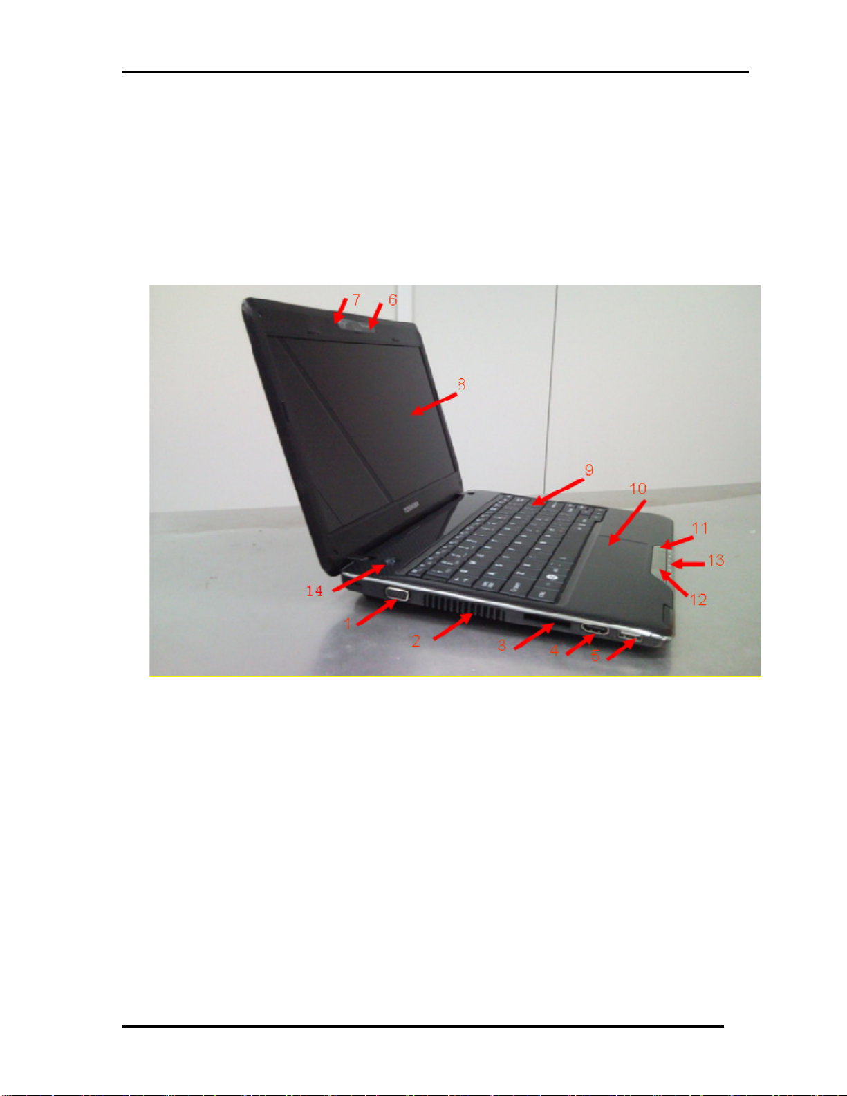
1. Extend Monitor connector 2. FAN HOLE
3. Bridge Media Slot 4. HDMI out port
USB port (USB Sleep and Charge function is supported by this port only.)
5.
6. Web Camera 7. Microphone
8. Display Screen 9. Keyboard
10. Touch Pad
11. Touch Pad Control Right Buttons
12. Touch Pad Control Light Buttons
13. LED light indicator
14. Power Button
Figure 1-1-1 Left of the computer
Satellite T110 / Satellite Pro T110 /PROTEGE110 Maintenance Manual (960-Q08)
3
Page 19
Chapter 1 Hardware Overview
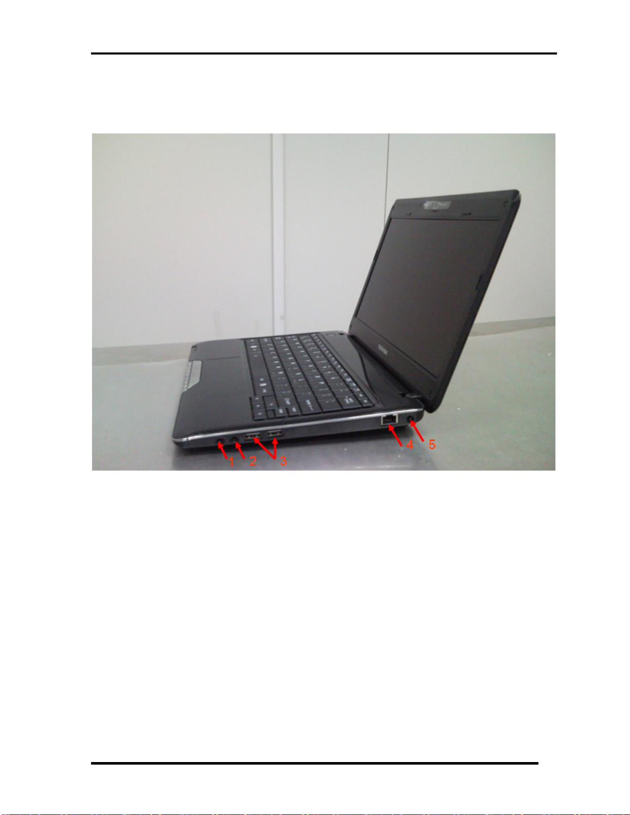
1. Headphone Jack
2. Microphone jack
3. USB port
4. LAN jack
5. DC-IN jack
Figure 1-1-2 Right of the computer
Satellite T110 / Satellite Pro T110 /PROTEGE110 Maintenance Manual (960-Q08)
4
Page 20
Chapter 1 Hardware Overview
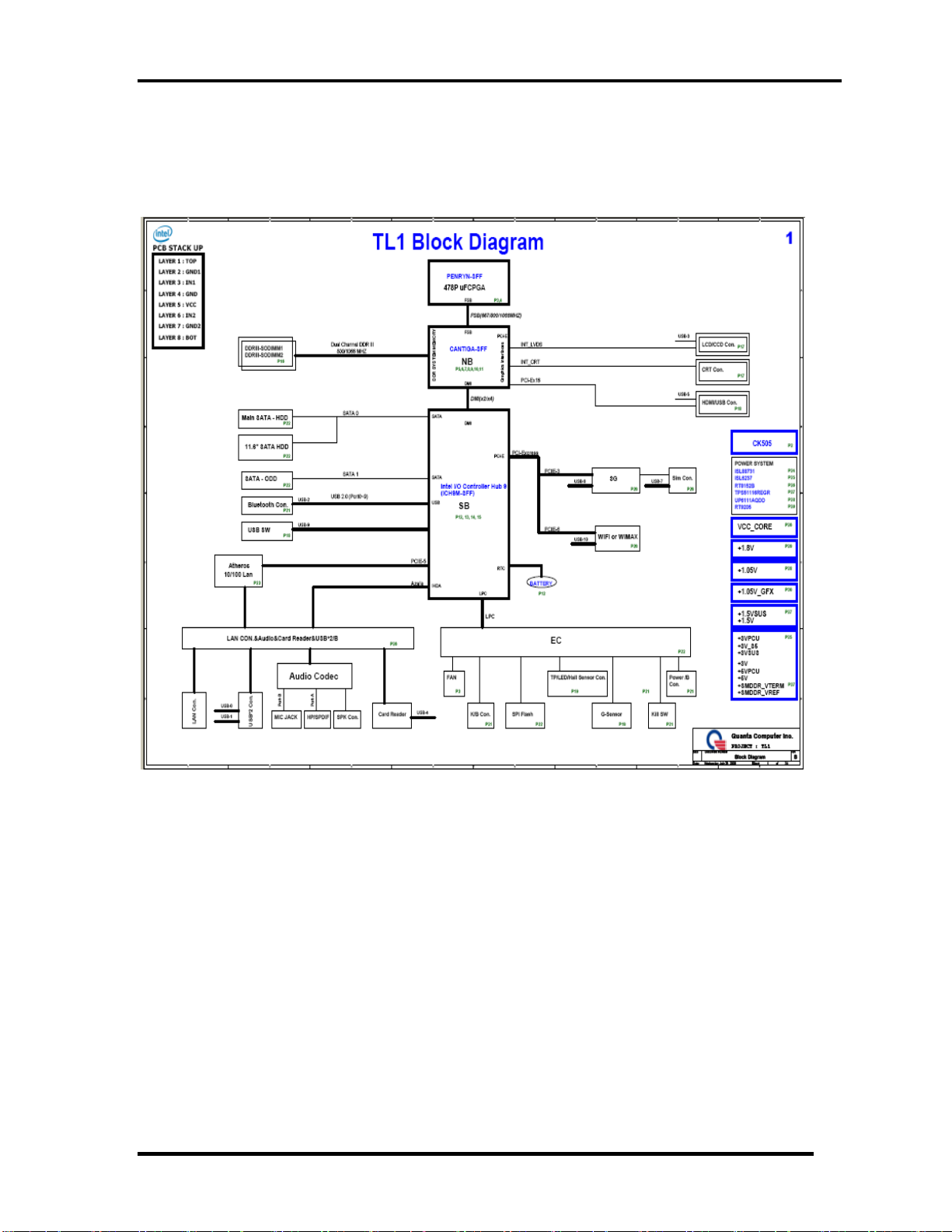
1.2 System Block Diagram
Figure 1-2-1 shows the system block diagram.
Figure 1-2-1 System block diagram for Intel Platform
Satellite T110 / Satellite Pro T110 /PROTEGE110 Maintenance Manual (960-Q08)
5
Page 21

Chapter 1 Hardware Overview
6
The PC contains the following components.
CPU
Intel® Core™2 Duo ULV CPU
SU2700 1.30GHz
CPU(956P)743 1.3G
Memory
Two memory slots capable of accepting DDRIII-SDRAM 1GB, 2GB or 4GB
memory modules for a maximum of 4GB.
204-pin SO-DIMM
1.5V operation
BIOS ROM (Flash memory)
16Mbit
Chipset
This gate array has the following elements and functions.
North Bridge (Intel GS40)
Penryn processor System Bus support
DRAM Controller: DDR3-1333/1066/800 support
* 1333/1066 memory module runs at 800MHz
DMI
1365-ball 27 x 25mm Micro FC-BGA Package
South Bridge (ICH9M-E SFF)
Direct Media Interface (DMI)
PCI Express
Serial ATA (SATA) Controller
PCI Interface
Low Pin count (LPC) interface
Serial Peripheral Interface (SPI)
DMA controller
Advanced Programmable Interrupt Controller (APIC)
USB Controllers
Satellite T110 / Satellite Pro T110 /PROTEGE110 Maintenance Manual (960-Q08)
Page 22

Chapter 1 Hardware Overview
7
USB Controllers
RTC
GPIO
Enhanced Power Management
SMBus 2.0
High Definition Audio Controller
569-pin 16mmx16mm mBGA Package
Other main system chips
• Clock Generator (CULV Platform: ICS9LPRS365BKLFT)
• EC/KBC –[W/CIR(Winbond WPCE775CA0DG)]
• HD Audio (CONEXANT CX20582-11Z)
• Card Reader controller (REALTEAK RTS5159 )
• 10/100 LAN controller (Atheros AR8132M)
Mini Card
Wireless LAN (BTO)
IEEE802.11b/g or IEEE802.11b/g/n
Wireless WAN (BTO)
HSPA
Blue tooth
Bluetooth V2.1+EDR. (BTO)
Satellite T110 / Satellite Pro T110 /PROTEGE110 Maintenance Manual (960-Q08)
Page 23
Chapter 1 Hardware Overview
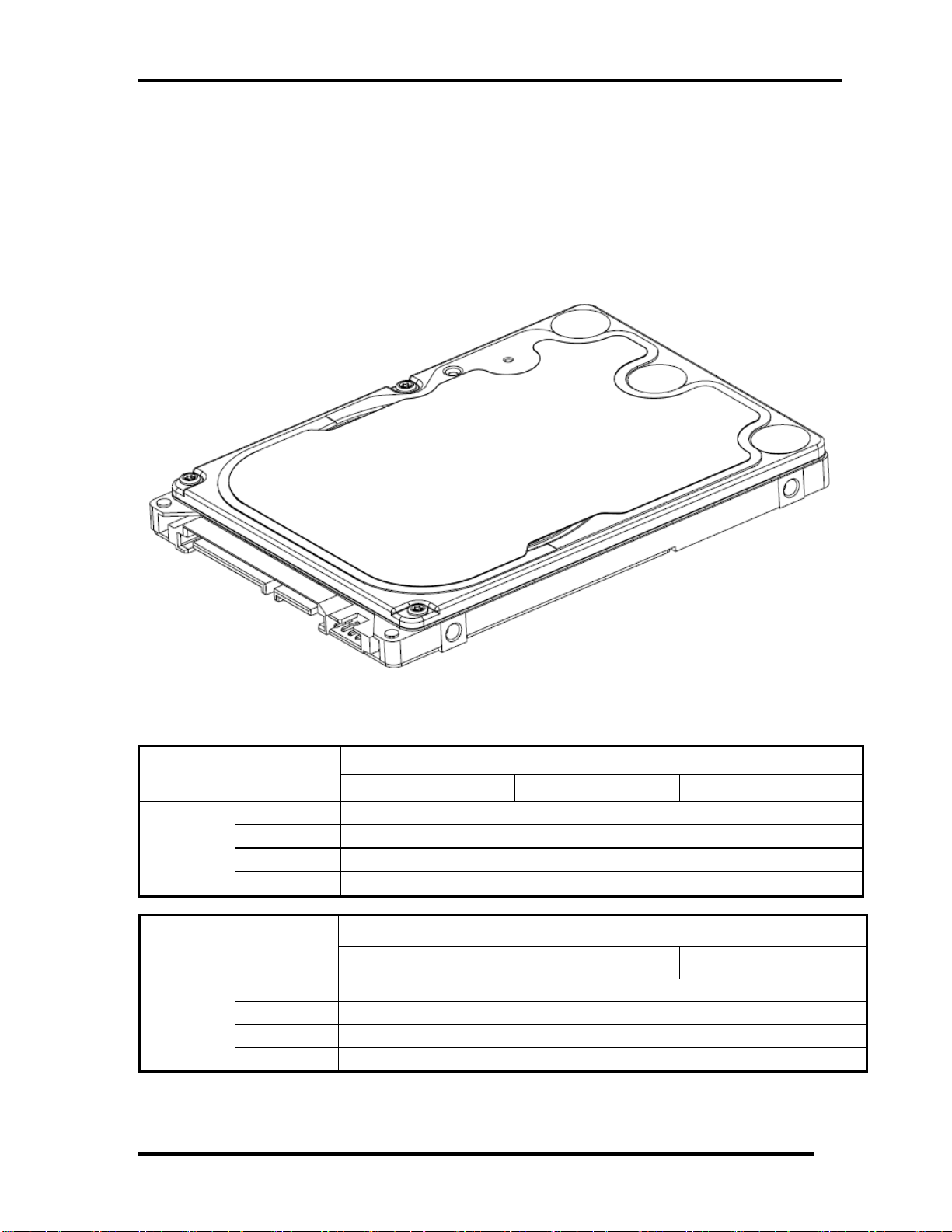
1.3 2.5-inch Hard Disk Drive
A compact, high-capacity HDD with a height of 9.5mm contains 2.5-inch magnetic disks and
magnetic heads.
Figure 1-3-1 shows a view of the 2.5-inch HDD and Tables 1-3-2 and 1-3-3 list the
specifications.
Outline
dimensions
Parameter
Outline
dimensions
Figure 1-3-1 2.5-inch HDD
Parameter
TOS MK2555GSX TOS MK3255GSX TOS MK5055GSX
Width (mm) 69.85
Height (mm) 9.5
Depth (mm) 100
Weight (g) 97/98/101/102
HTS545025B9A300 HTS545032B9A300 HTS545050B9A300
Width (mm) 69.85
Height(mm) 9.5
Depth (mm) 100
Weight (g) 101(Max)
Standard value
Standard value
Satellite T110 / Satellite Pro T110 /PROTEGE110 Maintenance Manual (960-Q08)
8
Page 24
Chapter 1 Hardware Overview
Parameter
Outline
dimensions
WD2500BEVT-26ZCT0 WD3200BEVT-26ZCT0
Width (mm) 69.85
Height (mm) 9.5
Length (mm) 100.0
Weight (g)
Standard value
99(Max)
Table 1-3-2 2.5-inch HDD dimensions
Parameter
Storagesize
(formatted)
Speed (RPM) 5400
Data transfer Rate
- To/From Media 363~952MB/S
- To/From Host 3GB/S
Bus Transfer Rate 3GB/S
Average random seek
time (read) (ms)
Power-on-to-ready
(sec)
TOS MK2555GSX TOS MK3255GSX TOS MK5055GSX
250GB 320GB 500GB
Specification
12
3.5(typ)/9.5(Max)
Parameter
Storage size
(formatted)
Speed (RPM)
Data transfer Rate
- To/From Media
- T0/From Host
Bus Transfer Rate 3GB/S
Average random
seek time (read) (ms)
Power-on-to-ready
(sec)
HTS545025B9A300 HTS545032B9A300 HTS545050B9A300
250GB 320GB 500GB
Specification
5400
363~952MB/S
3GB/S
12
3.5
Satellite T110 / Satellite Pro T110 /PROTEGE110 Maintenance Manual (960-Q08)
9
Page 25
Chapter 1 Hardware Overview
Parameter
Storage size
(formatted)
Speed (RPM) 5,400
Data transfer Rate
- To/From Media 933MB/s Max.
- T0/From Host 3Gb/s
bus transfer rate 3Gb/s
Average random seek
time (read) (ms)
Power-on-to-ready
(sec)
WD2500BEVT-26ZCT0 WD3200BEVT-26ZCT0
250GB 320GB
Specification
12.0ms/13.0ms
4.0 (typ)
Table 1-3-3 2.5-inch HDD Specification
Satellite T110 / Satellite Pro T110 /PROTEGE110 Maintenance Manual (960-Q08)
10
Page 26
Chapter 1 Hardware Overview
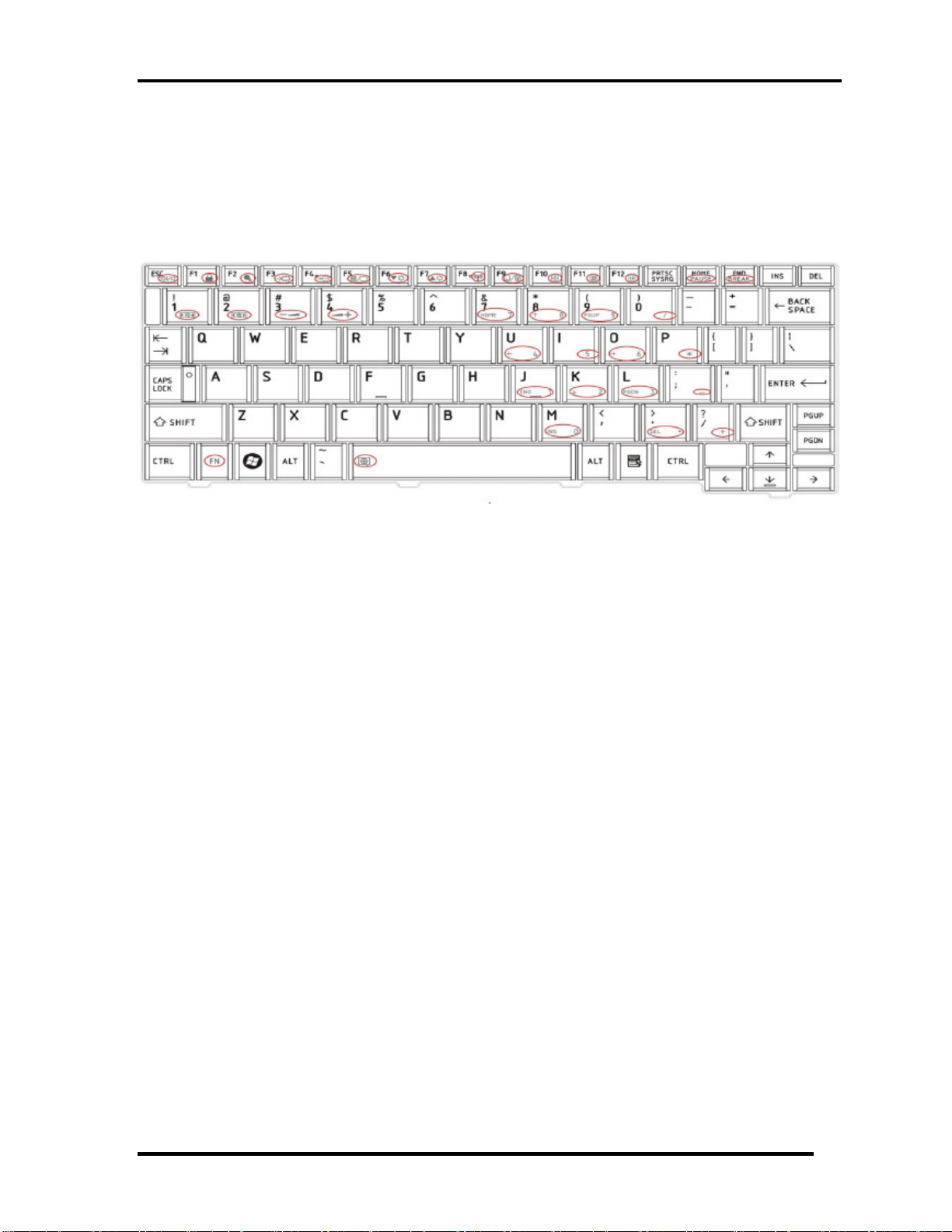
1.4 Keyboard
The Satellite T110, Satellite Pro T110, and PORTEGE T110 keyboard is for US style
Figure 1-4-1 is a view of the keyboard for US style
Figure 1-4-1 Keyboard for US style
See Appendix E for details of the keyboard layout
Satellite T110 / Satellite Pro T110 /PROTEGE110 Maintenance Manual (960-Q08)
11
Page 27
Chapter 1 Hardware Overview
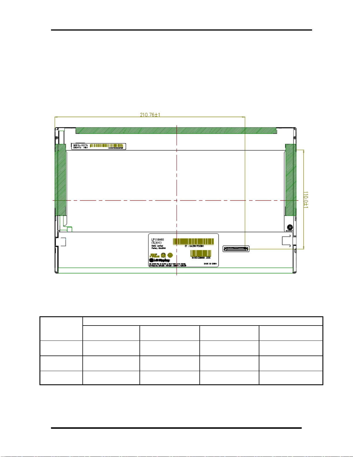
1.5 TFT Color Display
The Satellite T110 use LED to control backlight.
LCD Module
Figure 1-5-1 shows a view of the LCD module and Table 1-5-2 lists the specifications.
Figure 1-5-1 LCD Module
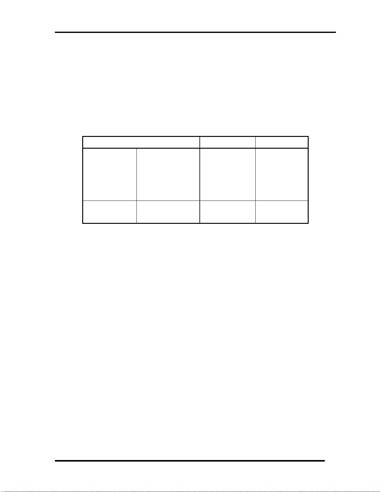
Specifications(WXGA+)
Item
Number of
Dots
Dot spacing
(mm)
Display
Colors
SAMSUNGA
LTN116AT01-T01
1,366 x 3(R,G,B) x
768
0.2265(H)×
0.2265(V)
262,144 colors 262,144 colors 262,144 colors 262,144 colors
CHI MEI
N116B6-L02
1,366 x 3(R,G,B) x
768
0.1875(H)×
0.1875(V)
LG
LP116WH1-TLA1
1,366 x 3(R,G,B) x
768
0.1875(H)×
0.1875(V)
AUO
B116XW02 V0
1,366 x 3(R,G,B) x
768
0.1875(H)×
0.1875(V)
Table 1-5-2 LCD module specifications
Satellite T110 / Satellite Pro T110 /PROTEGE110 Maintenance Manual (960-Q08)
12
Page 28

Chapter 1 Hardware Overview
1.6 Power Rails
Table 1-6-1 lists the power rail output specifications of CULV platform.
Power supply (Yes/No)
Name
Voltage [V]
Power OFF
Suspend mode
Power OFF
Boot mode
No Battery
+5VPCU
+5V
+3VPCU
+3V_S5
+3VSUS
+3V
+1.8VSUS
+SMDDR_VTERM
+SMDDR_VREF
+1.8V
+1.5V
+1.2V
+1.05v
+NB_CORE
VCC_CORE
5
5 No No No
3.3
3.3
3.3
3.3 No No No
1.8
1.8
1.8
1.8 No No No
1.5 No No No
1.25 No No No
1.05 No No No
1.0~1.2 No No No
0.7~1.2 No No No
Yes Yes
Yes Yes
Yes
Yes
Yes
Yes
Yes
No No
No No
No No
No No
No No
No
No
Table 1-6-1 CULV Power supply output rating
Satellite T110 / Satellite Pro T110 /PROTEGE110 Maintenance Manual (960-Q08)
13
Page 29
Chapter 1 Hardware Overview
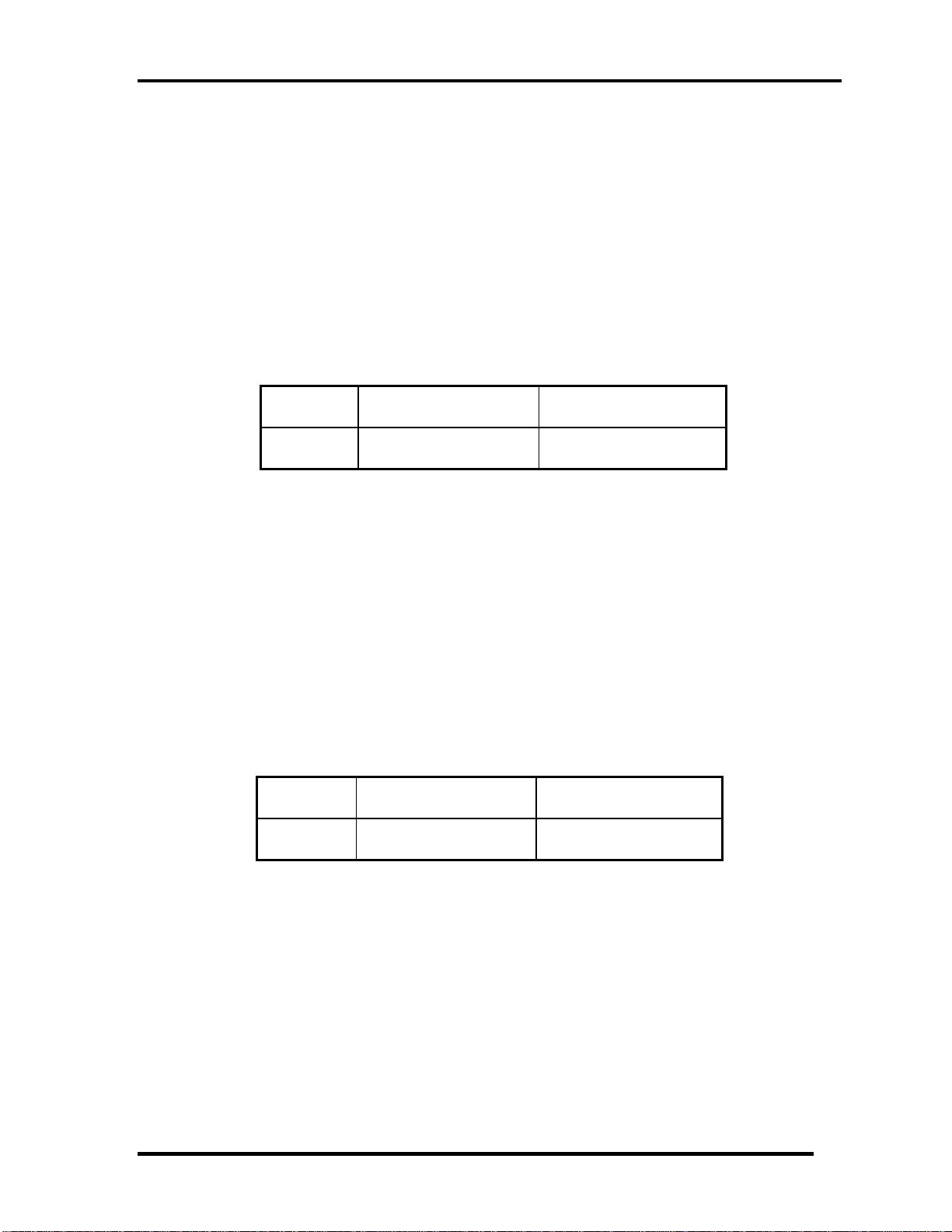
1.7 Batteries
The PC has the following two batteries.
Main battery
Real time clock (RTC) battery
Table 1-7-1 lists the specifications for these two batteries.
Battery Name Battery Element Output Voltage
Main battery
6 Cells Lithium ion 10.8 V
Real time clock
(RTC) battery
COIN Type Lithium ion 3V
Table 1-7-1 Battery specifications
1.7.1 Main Battery
The main battery is the primary power supply for the computer when the AC adapter is not
connected. In Standby, the main battery maintains the current status of the computer.
Satellite T110 / Satellite Pro T110 /PROTEGE110 Maintenance Manual (960-Q08)
14
Page 30
Chapter 1 Hardware Overview
1.7.2 Battery Charging Control
Battery charging is controlled by a power supply microprocessor. The power supply
microprocessor controls power supply and detects a full charge when the AC adaptor and
battery are connected to the computer.
Battery Charge
When the AC adapter is connected, normal charging is used while the system is
turned on and quick charge is used while the system is turned off. Refer to the
following Table 1-7-2.
Power ON Power OFF
6 cell 5 ~ 10 hours about 5 hours
Table 1-7-2 Time required for charges of main battery
Charge is stopped in the following cases.
1. The main battery is fully charged
2. The main battery is removed
3. Main battery or AC adapter voltage is abnormal
4. Charging current is abnormal
Data preservation time
When turning off the power in being charged fully, the preservation time is as
following Table 1-7-3.
Sleep Shut down
6 cell About 3 days About 30 days
Table 1-7-3 Data preservation time
Satellite T110 / Satellite Pro T110 /PROTEGE110 Maintenance Manual (960-Q08)
15
Page 31

Chapter 1 Hardware Overview
1.7.3 RTC Battery
The RTC battery provides the power supply to maintain the date, time, and other system
information in memory.
Table 1-7-4 lists the Time required for charges of RTC battery and data preservation time.
Condition Time
Charging time About 24 hours
Data retaining time About 30 days
Table 1-7-4 Time required for charges of RTC battery
Satellite T110 / Satellite Pro T110 /PROTEGE110 Maintenance Manual (960-Q08)
16
Page 32

Chapter 1 Hardware Overview
1.8 AC Adapter
The AC adapter is used to charge the battery.
Table 1-8-1 lists the AC adapter specifications.
Parameter
With Led
Power 65W 65W
Input voltage AC 100V/240V
Input frequency 50Hz/60Hz
Input current
Output voltage DC 19V
Output current 3.42A 3.42A
DELTA/ LITE-ON
3pin
Specification
DELTA/ LITE-ON 2pin
≦ 1.5A
Table 1-8-1 AC adapter specifications
Satellite T110 / Satellite Pro T110 /PROTEGE110 Maintenance Manual (960-Q08)
17
Page 33

Chapter 2
Troubleshooting Procedures
Satellite T110 / Satellite Pro T110 / PORTEGE T110 Maintenance Manual (960-Q08)
Page 34

Chapter 2 Troubleshooting Procedures
Chapter 2 Contents
Chapter 2 Contents
2.1 Troubleshooting............................................................................................................1
2.2 Troubleshooting Flowchart........................................................................................... 2
2.3 Power Supply Troubleshooting..................................................................................... 6
Procedure 1 Power Status Check .................................................................. 6
Procedure 2 Connection Check..................................................................... 8
Procedure 3 Charging Check ........................................................................ 8
Procedure 4 Replacement Check ................................................................ 10
2.4 System Board Troubleshooting................................................................................... 11
Procedure 1 Message Check ....................................................................... 12
Procedure 2 Debugging Port Check............................................................13
Procedure 3 Replacement Check ................................................................ 13
2.5 Hard Disk Drive Troubleshooting .............................................................................. 14
Procedure 1 Partition Check........................................................................ 14
Procedure 2 Message Check ....................................................................... 15
Procedure 3 Diagnostic Test Program Execution Check............................ 16
Procedure 4 Connector Check and Replacement Check............................. 17
2.6 Keyboard Troubleshooting ......................................................................................... 18
Procedure 1 Diagnostic Test Program Execution Check............................ 18
Procedure 2 Connector Check and Replacement Check............................. 19
2.7 Touch pad Troubleshooting........................................................................................ 20
Procedure 1 Diagnostic Test Program Execution Check............................ 20
Procedure 2 Connector Check and Replacement Check............................. 21
2.8 Display Troubleshooting............................................................................................. 22
Procedure 1 External Monitor Check.......................................................... 22
Procedure 2 Diagnostic Test Program Execution Check............................ 22
Procedure 3 Connector and Cable Check.................................................... 23
Satellite T110 / Satellite Pro T110 / PORTEGE T110 Maintenance Manual (960-Q08)
Page 35

Chapter 2 Troubleshooting Procedures
Procedure 4 Replacement Check ................................................................ 24
2.9 LAN Troubleshooting................................................................................................. 25
Procedure 1 Diagnostic Test Program Execution Check............................ 25
Procedure 2 Connector Check and Replacement Check............................. 25
2.10 Wireless LAN Troubleshooting.................................................................................. 26
Procedure 1 Transmitting-Receiving Check............................................... 26
Procedure 2 Antennas' Connection Check.................................................. 27
Procedure 3 Replacement Check ................................................................ 28
2.11 Sound Troubleshooting............................................................................................... 29
Procedure 1 Connector Check..................................................................... 29
Procedure 2 Replacement Check ................................................................ 30
2.12 Bluetooth Troubleshooting ......................................................................................... 31
Procedure 1 Connector Check and Replacement Check............................ 31
2.13 HDMI Troubleshooting .............................................................................................. 32
Procedure 1 Connector Check and Replacement Check............................. 32
Procedure 2 External Monitor Check.......................................................... 32
Procedure 3 Connector and Cable Check.................................................... 33
Procedure 4 Replacement Check ................................................................ 34
2.14 Memory Troubleshooting ........................................................................................... 35
Procedure 1 Diagnostic Test Program Execution Check............................ 35
Procedure 2 Connect Check and Replacement Check................................ 35
2.15 3G Troubleshooting.................................................................................................... 36
Procedure 1 Connect Check and Replacement Check................................ 36
2.16 Camera Troubleshooting............................................................................................. 37
Procedure 1 Camera Execution Check........................................................ 37
Procedure 2 Connect Check and Replacement Check................................ 37
2.17 Microphone Troubleshooting...................................................................................... 38
Procedure 1 Sound Recorder Execution Check .......................................... 38
Procedure 2 Connect Check and Replacement Check................................ 38
2.18 CRT Troubleshooting ................................................................................................. 39
Procedure 1 External Monitor Check.......................................................... 39
Procedure 2 Connector and Cable Check.................................................... 39
Satellite T110 / Satellite Pro T110 / PORTEGE T110 Maintenance Manual (960-Q08)
Page 36

Chapter 2 Troubleshooting Procedures
Procedure 3 Replacement Check ................................................................ 39
2.19 USB Troubleshooting ................................................................................................. 40
Procedure 1 Diagnostic Test Program Execution Check............................ 40
Procedure 2 Connect Check and Replacement Check................................ 40
2.20 LED Troubleshooting ................................................................................................. 41
Procedure 1 Each function Execution Check.............................................. 41
Procedure 2 Connect Check and Replacement Check................................ 41
Satellite T110 / Satellite Pro T110 / PORTEGE T110 Maintenance Manual (960-Q08)
Page 37

Chapter 2 Troubleshooting Procedures
2
2.1 Trouble shooting
Chapter 2 describes how to determine which Field Replaceable Unit (FRU) in the computer
is causing the computer to malfunction.
The FRUs covered are:
1. Power supply 7. LAN 13. 3G
2. System Board 8. Wireless LAN 14. Camera
3. SATA HDD 9. Sound 15. Microphone
4. Keyboard 10. Bluetooth 16. Ext CRT
5. Touch pad 11. HDMI 17. USB
6. Display 12. Memory 18 LED
The Test Program operations are described in Chapter 3. Detailed replacement procedures are
described in Chapter 4.
NOTE: After replacing the system board, it is necessary to execute the subtest 01 initial
configuration of the 3.3 Setting of the hardware configuration in Chapter 3.
The implement for the Diagnostics procedures is referred to Chapter 3. Also, following
implements are necessary:
1. Phillips screwdrivers (For replacement procedures)
2. Implements for debugging port check
Toshiba Free-DOS system
Satellite T110 / Satellite Pro T110 / PORTEGE T110 Maintenance Manual (960-Q08)
1
Page 38

Chapter 2 Troubleshooting Procedures
2.2 Troubleshooting Flowchart
Use the flowchart in Figure 2-2-1 as a guide for determining which troubleshooting
procedures to execute. Before going through the flowchart steps, verify the following:
Ask customer to enter the password if a password is registered.
Verify with the customer that Toshiba Windows is installed on the hard disk. Non-
Windows operating systems can cause the computer to malfunction.
Make sure all optional equipment is removed from the computer.
Satellite T110 / Satellite Pro T110 / PORTEGE T110 Maintenance Manual (960-Q08)
2
Page 39

Chapter 2 Troubleshooting Procedures
Figure 2-2-1 Troubleshooting flowchart (1/2)
Satellite T110 / Satellite Pro T110 / PORTEGE T110 Maintenance Manual (960-Q08)
3
Page 40

Chapter 2 Troubleshooting Procedures
Figure 2-2-1 Troubleshooting flowchart (2/2)
If the diagnostics program cannot detect an error, the problem may be intermittent. The Test
program should be executed several times to isolate the problem. Check the Log Utilities
function to confirm which diagnostic test detected an error(s), and then perform the
appropriate troubleshooting procedures as follows:
1. If an error is detected on the system test, memory test, display test, expansion test,
real timer test, sound test or LAN/Bluetooth test, perform the System Board
Troubleshooting Procedures in Section 2.4.
2. If an error is detected on the hard disk test, perform the HDD Troubleshooting
Procedures in Section 2.5.
3. If an error is found on the keyboard test (DIAGNOSTICS TEST) and pressed key
display test, perform the Keyboard Troubleshooting Procedures in Section 2.6.
Satellite T110 / Satellite Pro T110 / PORTEGE T110 Maintenance Manual (960-Q08)
4
Page 41

Chapter 2 Troubleshooting Procedures
4. If an error is found on the touch pad test, perform the Touch pad Troubleshooting
Procedures in Section 2.7.
5. If an error is detected on the display test, perform the Display Troubleshooting
Procedures in Section 2.8.
6. If an error is detected on the LAN test, perform the LAN Troubleshooting Procedures
in Section 2.9.
7. If an error is detected on the Wireless LAN test, perform the Wireless LAN
Troubleshooting Procedures in Section 2.10.
8. If an error is detected on the sound test, perform the Sound Troubleshooting
Procedures in Section 2.11.
9. If an error is detected on the Bluetooth test, perform the Bluetooth Troubleshooting
Procedures in Section 2.12.
10. If an error is detected on the HDMI test, perform the HDMI Troubleshooting
Procedures in Section 2.13
Satellite T110 / Satellite Pro T110 / PORTEGE T110 Maintenance Manual (960-Q08)
5
Page 42

Chapter 2 Troubleshooting Procedures
2.3 Power Supply Troubleshooting
The power supply controller controls many functions and components. To determine if
power supply is functioning properly, start with
Procedure 1 and continue with the other
the
Procedures as instructed. The procedures described in this section are:
Procedure 1
: Power Status Check
Procedure 2: Connection Check
Procedure 3: Charging Check
Procedure 4: Replacement Check
Procedure 1 Power Status Check
The following LED indicates the power supply status:
Battery LED
DC IN LED
The Power Supply control displays the power supply status with the Battery LED and the DC
IN LED as listed in the tables below.
Battery icon Power supply status
Lights Orange Battery is charged and the AC adapter is conn ected. It has
no relation with ON/OFF of the system power.
Lights Green Battery is fully charged and the AC adapter is connected. It
has no relation with ON/OFF of the system power.
Blinks Orange
(even intervals)
Doesn’t light Any condition other than those above.
The battery level is low while the system power is ON.
Table 2-3-1 Battery icon
DC IN icon Power supply status
Lights Green DC power is being supplied from the AC adapter.
Blinks Orange Power supply malfunction*1
Doesn’t light Any condition other than those above.
Table 2-3-2 DC IN icon
Satellite T110 / Satellite Pro T110 / PORTEGE T110 Maintenance Manual (960-Q08)
6
Page 43

Chapter 2 Troubleshooting Procedures
*1 When the power supply controller detects a malfunc
tion, the DC IN icon blinks orange
and perform the following procedure.
When the icon is blinking, perform the following procedure.
1. Remove the battery pack and the AC adapter.
2. Re- e dapter.
If the icon bove, check the followings:
Check 1 o to Procedure 2.
attach the batt ry pack and the AC a
is still blinking after the operation a
If the DC IN icon blinks orange, g
Check 2 If the DC IN icon does not light, go to Procedure 3.
Check 3 If the battery icon does not light orange or green, go to Procedure 4.
NOTE: Use a supp
lied AC adapter.
Satellite T110 / Satellite Pro T110 / PORTEGE T110 Maintenance Manual (960-Q08)
7
Page 44

Chapter 2 Troubleshooting Procedures
Procedure 2 Connection Check
The wiring diagram related to the power supply is shown below:
An o
y of the c nnectors may be disconnected. Perform Check 1.
Ch o the
eck 1 Make sure the AC adapter and the AC power cord is firmly plugged int
PCN1 connector and wall outlet. If these cables are connected firmly, go to Check
2.
Check 2 Replace the AC adapter and the AC power cord with new ones.
If the DC IN icon does not light, go to Procedure 4.
If the battery icon does not light, go to Check 3.
Check 3 Make sure the main battery pack is installed in the computer correctly. If the
battery is properly installed and the battery icon still does not light, go to
Procedure 4.
Procedure 3 Charging Check
Check if the power supply controller charges the battery pack properly. Perform the
following procedures:
Check 1 Make sure the AC adapter is firmly plugged into the DC IN socket.
Check 2 Make sure the battery pack is properly installed. If it is properly installed, go to
Check 3.
Check 3 The battery pack may be completely discharged. Wait a few minutes to charge the
battery pack while connecting the battery pack and the AC adapter. If the battery
pack is still not charged, go to Check 4.
Check 4 The battery’s temperature is too high or low. Leave the battery for a while to
adjust it in the right temperature. If the battery pack is still not charged, go to
Check 5.
Check 5 Replace the battery pack with a new one. If the battery pack is still not charged,
Satellite T110 / Satellite Pro T110 / PORTEGE T110 Maintenance Manual (960-Q08)
8
Page 45

Chapter 2 Troubleshooting Procedures
go to Procedure 4.
Satellite T110 / Satellite Pro T110 / PORTEGE T110 Maintenance Manual (960-Q08)
9
Page 46

Chapter 2 Troubleshooting Procedures
Procedur ent Check
e 4 Replacem
The power is supplied to the system board by the AC adapter. If either the AC adapter or the
system board was damaged, perform the following Checks.
To disassemble the computer, follow the steps described in Chapter 4, Replacement
Procedures.
When AC adapter is connected;
Check 1 AC adapter may be faulty. Replace the AC adapter with a new one. If the problem
still occurs, perform Check 2.
Check 2 System board may be faulty. Replace the system board with a new one.
When AC adapter is not connected ;
(When driving with battery pack)
Check 1 Battery pack may be faulty. Replace it with a new one. If the problem still occurs,
perform Check 2.
Check 2 System board may be faulty. Replace it with a new one.
Satellite T110 / Satellite Pro T110 / PORTEGE T110 Maintenance Manual (960-Q08)
10
Page 47

Chapter 2 Troubleshooting Procedures
2.4 System Board Troublesho oting
This section describes how to determine if the system board
is malfunctioning or not. Start
with Procedure 1 and continue with the other procedures as instructed. The procedures
described in this section are:
Procedure 1: Message Check
Procedure 2 Diagno
stic Test Program Execution Check
Procedure 3: Replacement Check
Satellite T110 / Satellite Pro T110 / PORTEGE T110 Maintenance Manual (960-Q08)
11
Page 48

Chapter 2 Troubleshooting Procedures
Procedure 1 Message Check
When the power is turned on, the system performs the Power on Self Test (POST) installed
in the BIOS ROM. The POST tests each IC on the system board and initializes it.
If an error message is
If t r rocedure 2.
here is no erro message, go to P
If Free-DOS or W .
shown on the display, perform Check 1.
indows is properly loaded, go to Procedure 4
Check 1 If one of the following error messages is displayed on the screen, press the F2 key
as the message instructs. These errors occur when the system configuration
preserved in the RTC memory (CMOS type memory) is not the same as the actual
configuration or when the data is lost.
If you press the F2 key as the message instructs, the SETUP screen appears to set
the system configuration.
Satellite T110 / Satellite Pro T110 / PORTEGE T110 Maintenance Manual (960-Q08)
12
Page 49

Chapter 2 Troubleshooting Procedures
Procedure 2 Diagnostic Test Program Execution Check
Execute the following tests from the Diagnostic Test Menu. These tests check the system
board. Refer to Chapter 3, Tests and Diagnostic, for more information on how to p
erform
these tests.
1. System test
2. Memory test
3. Keyboard test
4. Display test
5. Hard Disk test
6. CPU Temperature test
7. Ma
8. BIO
9. Sys
10. Wi
11. LA
in Battery test
S test
tem Status LED test
reless LAN test
N/Sound test
12. UUID test-DMI Information (Write DMI)
If an error is detected during these tests, go to Procedure 3.
Procedure 3 Replacement Check
System board may be faulty. Disassemble the computer following the steps described in
Chapter 4, Replacement Procedures and replace system board with a new one.
Satellite T110 / Satellite Pro T110 / PORTEGE T110 Maintenance Manual (960-Q08)
13
Page 50

Chapter 2 Troubleshooting Procedures
2.5 SATA Hard Disk Drive Troubleshooting
To check if HDD is malfunctioning or not, follow the troubleshooting procedures below as
instructed.
Procedur
Procedure
Procedure 4:
Procedure 5: Conn
e 1: Partition Check
2: Message Check
3: Format Check
e Procedur
Diagnostic Test Program Execution Check
ector Check and Replacement Check
CAUTION: The contents
of the hard disk will be erased when the HDD troubleshooting
procedures are executed. Transfer the contents of the hard disk to other
storage drive(s). For the backup, refer to the User’s Manual.
Procedure 1 Partition Check
Insert the Toshiba USB memory and start th
e computer. Perform the following checks:
Check 1 Input C: and press Enter. If you cannot change to drive C, go to Check 2. If y
can change to drive C, go to Procedure 2.
ou
heck 2 input USB memories and press Enter. Choose Display Partition Information from
C
the menu. If drive C is listed in the Display Partition Information, go to Check 3.
If drive C is not listed, return to the menu and choose the option to create a DOS
partition or a logical DOS drive on drive C. If the problem still occurs, go to
Procedure 2.
heck 3 If drive C is listed as active in the menu, go to Check 4. If drive C is not listed as
C
active, return to the menu and choose the option to set the active partition for
drive C. Then go to Procedure 2.
heck 4 Remove the USB memory and reboot the computer. If the problem still occurs, go
C
to Procedure 2. Otherwise, the 2.5” HDD is operating normally.
Satellite T110 / Satellite Pro T110 / PORTEGE T110 Maintenance Manual (960-Q08)
14
Page 51

Chapter 2 Troubleshooting Procedures
Procedure 2 Message Check
When the power is turned on, the system performs the Initial Reliability Test (IRT) installed
in the BIOS ROM. When the test detects an error, an error message is displayed on the scree
n.
Turn on the computer and check the message on the screen. When an OS starts from the 2.5”
HDD, go to Procedure 3. Otherwise, start with Check 1 below and perform the other checks
as instructe
d.
Check 1 ages appears, go to Check 2. If the following
If either of the following mess
messages do not appear, perform Check 3.
Insert system disk in drive
Press any key when ready .....
or
Non-System disk or disk error
Replace and press any key when ready
Check 2 Using the SYS command of the Free-DOS; transfer the system to the 2.5” HDD.
If the system is not transferred, go to Procedure 3. Refer to the Free-DOS Manual
for detailed operation.
If the following message appears on the display, the system program has been
transferred to the HDD.
System Transferred
If an error message appears on the display, perform Check 3.
Check 3
2.5” HDD(s) and the connector(s) of system board may be defective (Refer to the
steps described in Chapter 4, Replacement Procedures for disassembling.). In
HDD(s) to the
connector(s) firm
ly. If it is (or they are) firmly connected, go to
sert
Procedure 3.
Satellite T110 / Satellite Pro T110 / PORTEGE T110 Maintenance Manual (960-Q08)
15
Page 52

Chapter 2 Troubleshooting Procedures
Procedure 3 Diagnostic Test Program Execution Check
The HDD test program is stored in the Diagnostics Disk. Perform all of the HDD tests in the
Hard Disk Drive Test. Refer to Chapter 3, Tests and Diagnostics, for more information about
the HDD test program.
If an error is detected during the HDD test, an error code and status will be displayed. The
error codes and
statuses are described in Table 2-5-1. If an error code is not displayed but the
problem still occurs, go to Procedure 5.
Code Statu
01 Bad Error Command
02 ror Bad Address Mark Er
04 Record Not Found
05 HDC Not Reset Error
07 Drive Not Initialized
09 DMA Boundary Error
0A Bad Sector
0B Bad Track Error
10 ECC Error
11 ECC Recover Enabled
20 HDC Error
40 Seek Error
80 Time Out Error
AA Drive Not Ready
BB Undefined Error
s
CC Write Fault
E0 Status Error
F0 No Sense Error
?? Other Error
Table 2-5-1 HDD error code & status
Satellite T110 / Satellite Pro T110 / PORTEGE T110 Maintenance Manual (960-Q08)
16
Page 53

Chapter 2 Troubleshooting Procedures
Procedure 4 Connector Check and Replacement Check
HDD(s) is/are connected to the connector(s) on the system board. The connection of HDD(s)
and board may be defec
tive. Otherwise, they may be faulty. Disassemble the computer
following instructions in Chapter 4, Replacement Procedures and perform the following
checks.
Check 1 Make sure HDD(s) is/are firm
ly connected to the connector(s) on the system
board.
If an the connections are loose, ly and repeat Procedure 1. If the
y of reconnect firm
prob still occurs, go to Check
lem 2.
Check 2 (One of) HDD(s) may be faulty. Replace it with a new one following the
instr ons in Chapter 4, Repl d check the operation. If the
ucti acement Procedures an
prob still occurs, perform Check
lem 3.
Check 3 Syst oard may be faulty. Replac ew one following the instructions
em b e it with a n
in Chapter 4, Replacement Proced
ures.
Satellite T110 / Satellite Pro T110 / PORTEGE T110 Maintenance Manual (960-Q08)
17
Page 54

Chapter 2 Troubleshooting Procedures
2.6 Keyboard Troubleshooting
To check if the computer’s keyboard is malfunctioning or not, follow the troubleshooting
procedures below as instructed.
Procedure 1: Diagnostic Test Program Execution Check
Procedure 2: Connector and Replacement Check
Procedure 1 Diagnostic Test Program Execution Check
Execute the Keyboard Test (DIAGNOSTIC TEST) and Pressed key display test in the
Diagnostic Program. Refer to Chapter 3, Tests and Diagnostics, for more information on how
to perform the test program.
If an error occurs, go to Procedure 2. If an error does not occur, keyboard is functioning
properly.
Satellite T110 / Satellite Pro T110 / PORTEGE T110 Maintenance Manual (960-Q08)
18
Page 55

Chapter 2 Troubleshooting Procedures
Procedure 2 Connector and Replacement Check
The connection of cable and board may be defective. Otherwise, they may be faulty.
Disassemble the computer following the steps described in Chapter 4, Replacement
Procedures, and perform the following checks:
Check 1 stem board. Make sure keyboard cable is firmly connected to sy
If the connection is loose, reconnect firmly and repeat Procedure 1. If the problem
still occurs, go to Check 2.
Check 2 Keyboard may be faulty. Replace it with a new one following the instructions in
Chapter 4, Replacement Procedures. If the problem still occurs, perform Check 3.
Check 3 System board may be faulty. Replace it with a new one following the instructions
in Chapter 4, Replacement Procedures.
Satellite T110 / Satellite Pro T110 / PORTEGE T110 Maintenance Manual (960-Q08)
19
Page 56

Chapter 2 Troubleshooting Procedures
2.7 Touch pad Troubleshooting
To check if the computer’s touch pad is malfunctioning or not, follow the troubleshoo
ting
procedures below as instructed.
Procedure 1: Diagnostic Test Program Execution Check
Procedure 2: Connector and Replacement Check
Procedure 1 Diagnostic Test Program Execution Check
Execute the Touch pad test in the Diagnostic Program. Refer to Chapter 3, Tests and
Diagnostics, for more information on how to perform the test program.
If an error occurs, go to Procedure 2. If an error does not occur, touch pad is functioning
properly.
Satellite T110 / Satellite Pro T110 / PORTEGE T110 Maintenance Manual (960-Q08)
20
Page 57

Chapter 2 Troubleshooting Procedures
Procedure 2 Connector and Replacement Check
The connection of cable and board may be defective. Otherwise, they may be faulty.
Disassemble the computer following the steps described in Chapter 4, Replacement
Procedures, and perform the following checks:
Check 1 oard. Make sure the cable is firmly connected to system b
If the connection is loose, reconnect firmly and repeat Procedure 1. If the problem
still occurs, go to Check 2.
Check 2 Touch Pad or the cable may be faulty. Replace it with a new one following the
instructions in Chapter 4, Replacement Procedures. If the problem still occurs,
perform Check 3.
Check 3 System board may be faulty. Replace it with a new one following the instructions
in Chapter 4, Replacement Procedures
Satellite T110 / Satellite Pro T110 / PORTEGE T110 Maintenance Manual (960-Q08)
21
Page 58

Chapter 2 Troubleshooting Procedures
2.8 Display Troubleshooting
T
o check if the computer’s display is malfunctioning or not, follow the troubleshooting
p
rocedures below as instructed.
Procedure 1: External Monitor Check
P
rocedure 2: Diagnostic Test Program Execution Check
Procedure 3: Connector and Cable Check
Procedure 4: Replacement Check
Procedure 1 External Monitor Check
Connect an external monitor to the computer’s external monitor port, and then boot the
computer. The computer automatically detects the external monitor.
When “Power on Display” setting is “Auto-Selected” (Default) in BIOS Setup Menu.
If this setting is “System LCD only”, external monitor cannot be displayed. The computer
automatically detects the external monitor.
If the extern
al monitor works correctly, the internal LCD may be faulty. Go to Procedure 3.
If the external monitor appears to have the same problem as the internal monitor, system
b
oard may be faulty. Go to Procedure 2.
Procedure 2 Diagnostic Test Program Execution Check
T y
he Displa Test program is stored in Diagnostics disk. This program checks the display
controller on system the computer and run the test.
board. Insert the Diagnostics disk, turn on
Refer to Chapter 3, Tests and Diagnostics for details. If an error is detected, go to Procedure 3.
Satellite T110 / Satellite Pro T110 / PORTEGE T110 Maintenance Manual (960-Q08)
22
Page 59

Chapter 2 Troubleshooting Procedures
Procedure 3 Connector and Cable Check
LCD Module is connected to system board by an LCD cable. Their cables may be
disconnected from system board. Disassemble the computer following the steps described in
Chapter 4, Replacement Procedures.
If the conn the problem still
occurs, go .
ection is loose, reconnect firmly and restart the computer. If
to Procedure 4
Satellite T110 / Satellite Pro T110 / PORTEGE T110 Maintenance Manual (960-Q08)
23
Page 60

Chapter 2 Troubleshooting Procedures
Procedure 4 Replacement Check
LCD module, LCD cable are connected to display circuits. Any of these componen
ts may be
faulty. Refer to Chapter 4, Replacement Procedures, for instructions on how to disassemble
the computer and then perform the fol
If characters or graphics on the internal display are not displayed clearly, perf
lowing checks:
orm
Check 1.
If some screen functions do not operate properly, perform Check 2.
If LED backlight remains lit when the display is closed, perform Check 3.
Check 1 LCD cable may be faulty. Replace LCD cable with a new one following the
instructions in Chapter 4, Replacement Procedure and test the display again. If the
problem still occurs, perform Check 2.
Check 2 LCD module may be faulty. Replace LCD module with a new one following the
instructions in Chapter 4, Replacement Procedure and test the display again. If the
problem still occurs, perform Check 3.
Check 3 System board may be faulty. Replace it with a new one following the instructions
in Chapter 4, Replacement Procedure.
Satellite T110 / Satellite Pro T110 / PORTEGE T110 Maintenance Manual (960-Q08)
24
Page 61

Chapter 2 Troubleshooting Procedures
2.9 LAN Troubleshooting
To check if the computer’s LAN is malfunctioning or not, follow the troubleshooting
procedures below as instructed.
Procedure 1: Diagnostic Test Program Execution Check
Procedure 2: Connector Check and Replacement Check
Procedur
Execute LA for
e 1 Diagnostic Test Program Execution Check
N test in the LAN test program. Refer to Chapter 3, Tests and Diagnostics
more information on how to perform the test program.
If any error
is detected by the test, go to Procedure 2.
Procedure 2 Connector Check and Replacement Check
The LAN f
defective o aulty.
unction is embedded on system board. If LAN malfunctions, its connection is
r LAN cable and system board may be f
Check 1 Make sure LAN cable is firmly connected to the connector CN1. If the problem
still occurs, perform Check 2.
No Separated LAN BOARD ,it’s assembled.
Check 2 LAN cable may be faulty. Replace it with a new one. If the problem still occurs,
perform Check 3.
Check 3 System board may be faulty. Replace it with a new one following the instruction in
Chapter 4.
Satellite T110 / Satellite Pro T110 / PORTEGE T110 Maintenance Manual (960-Q08)
25
Page 62

Chapter 2 Troubleshooting Procedures
2.10 Wireless LAN Troubleshooting
To check if the computer's Wireless LAN is malfunctioning or not, follow the troubles
procedures below as instructed.
Procedure 1: Transmitting-Receiving Check
Procedure 2: Antennas' Connection Check
Procedure 3: Replacement Check
Procedure 1 Transmitting-Receiving Check
Before starting the test, make sure wireless communica
Check 1 Execute Wireless LAN test program to che
tion is enabled in BIOS setup
ck the transmitting-receiving function
of wireless LAN. You will need a second computer that can communicate by
wireless LAN. Perform the test following the instructions d
escribed in Chapter 3.
If the computer passes the test, the function is correctly working. If the computer
does not pass the test, perform Procedure 2.
hooting
Satellite T110 / Satellite Pro T110 / PORTEGE T110 Maintenance Manual (960-Q08)
26
Page 63

Chapter 2 Troubleshooting Procedures
Procedure 2 Antennas' Connection Check
The wireless LAN function-wiring diagram is shown below:
Any of the connections may be defective. Disassemble the computer following the steps
described in Chapter 4, Replacement Procedures, and perform the following checks:
Make sure the wireless communication is Enabled in BIOS setup. Check 1
If the Wireless communication is "Disabled"
, change it to "Enabled". If the
problem still occurs, perform Check 2.
Check 2 Make sure wireless LAN card is firmly connected to the CN22 on system board. If
the connector is defective, connect it firmly and perform Procedure 1. If the
problem still occurs, perform Check 3.
Check 3 Make sure that wireless LAN antenna cables (black and white) are firmly
connected to the connectors on Wireless LAN card. If wireless LAN antenna
cables are not connected properly, connect them firmly and perform Procedure 1.
If the problem still occurs, go to the procedure 3.
Satellite T110 / Satellite Pro T110 / PORTEGE T110 Maintenance Manual (960-Q08)
27
Page 64

Chapter 2 Troubleshooting Procedures
Procedure 3 Replacement Check
Wireless LAN card, wireless LAN antenna or system board may be faulty. Refer to Chapter 4,
Replacement Procedures, for instructions on how to disassemble the computer and then
perform the following checks:
Check 1 Wireless LAN antenna may be faulty. Replace it with a new one following the
instructions in Chapter 4, Replacement Procedures. If the problem still occurs,
perform Check 2.
Check 2 Wireless LAN card may be faulty. Replace it with a new one following the
instructions in Chapter 4, Replacement Procedures. If the problem still occurs,
perform Check 3.
ons Check3 System board may be faulty. Replace it with a new one following the instructi
in Chapter 4, Replacement Procedures.
Satellite T110 / Satellite Pro T110 / PORTEGE T110 Maintenance Manual (960-Q08)
28
Page 65

Chapter 2 Troubleshooting Procedures
2.11 Sound Troubleshooting
To check if the sound function is malfunctioning or not, follow the troubleshooting proce
below as instructed.
Procedure 1: Connector Check
Procedure 2: Replacement Check
Procedure 1 Connector Check
The conne
ction of sound system is shown in the following figure.
As the connection may be defective, disassemble the PC and check each connection.
If the problem still occurs, go to Procedure 2.
dures
Satellite T110 / Satellite Pro T110 / PORTEGE T110 Maintenance Manual (960-Q08)
29
Page 66

Chapter 2 Troubleshooting Procedures
Procedure 2 Replacement Check
If External microphone/Headphone does not work properly, perform check 1.
If internal microphone /Speaker do not work properly, perform check 2.
If HP o heck 3.
ut does not work properly, perform c
If Volume control does not work properly, perform check 4.
Check 1 External microphone/Headphone may be faulty. Replace it with a new one
following the steps in Chapter 4. If the problem still occurs, perform Check 5.
Check 2 Internal microphone /Speaker may be faulty. Replace it with a new one following
the steps in Chapter 4. If the problem still occurs, perform Check 5.
Check 3 HP out may be faulty. Replace it with a new one following the steps in Chapter 4.
If the problem still occurs, perform Check 5.
Check 4 Volume control may be faulty. Replace it with a new one following the step
s in
Chapter 4. If the problem still occurs, perform Check 6.
Check 5 Flat cables between AD board/Speak
er and system board may be faulty. Replace it
with new cable following the instructions in Chapter 4. If the problem still occurs,
perform Check 6.
Check 6 Audio board/System board may be faulty. Replace it with a new one following the
instructions in Chapter 4.
Satellite T110 / Satellite Pro T110 / PORTEGE T110 Maintenance Manual (960-Q08)
30
Page 67

Chapter 2 Troubleshooting Procedures
2.12 Bluetooth Troubleshooting
To check if the computer’s Bluetooth is malfunctioning or not, follow the troublesh
procedure below as instructed.
Procedure 1 Connector Check and Replacem
h Bluetooth module is connected to system board. If Bluetooth malfunctions, its
T e
onnection is defective or Bluetooth cable and system board may be faulty.
c
Check 1
Make sure Bluetooth cable is firmly connected to the connector CN12 (system
ent Check
board). If the problem still occurs, perform Check 2.
ooting
Check 2
Bluetooth cable may be faulty. Replace it with a new one. If the problem s till
occurs, perform Check 3.
Check 3 eplace it with a new one following the steps in Chapter
Bluetooth may be faulty. R
4. If the problem still occurs, perform Check 4.
Check 4 System board may be faulty. Replace it with a new one following the instruction in
Chapter 4.
Satellite T110 / Satellite Pro T110 / PORTEGE T110 Maintenance Manual (960-Q08)
31
Page 68

Chapter 2 Troubleshooting Procedures
2.13 HDMI Troubleshooting
To check if the computer’s HDMI is malfunctioning or not, follow the troubleshooting
procedures below as instructed.
Procedure 1: External HDMI Monitor Check
Procedure 2: Connector and Cable Check
Procedure 3: Replacement Check
Procedure 1 Connector Check and Replacement Check
The HDMI port is connected to system board. If HDMI malfunctions, its connection is
defective or HDMI cable and system board may be faulty.
Check 1 Make sure HDMI cable is firmly connected to the connector CN11 (system board).
If the problem still occurs, perform Procedure 2.
Procedure 2 External Monitor Check
onitor to the comConnect an external m puter’s HDMI port, and then boot the computer. The
computer automatically detects the external monitor.
If the exter ay be faulty. Go to Procedure 3.
nal monitor works correctly, the internal LCD m
If the external monitor appears to have the same problem as the internal monitor, system
board may be faulty. Go to Procedure 2.
Satellite T110 / Satellite Pro T110 / PORTEGE T110 Maintenance Manual (960-Q08)
32
Page 69

Chapter 2 Troubleshooting Procedures
Procedure 3 Connector and Cable Check
HDMI monitor connected to HDMI&USB board by an HDMI cable.
If the connection is loose, reconnect firmly and restart the computer. If the problem still
occurs, go to Procedure 4.
Satellite T110 / Satellite Pro T110 / PORTEGE T110 Maintenance Manual (960-Q08)
33
Page 70

Chapter 2 Troubleshooting Procedures
Procedure 4 Replacement Check
HDMI signals are connected to display circuits via HDMI cable and HDMI&USB board. Any
of these components may be faulty. Refer to Chapter 4, Replacement Procedures, for
instructions on how to disassemble the computer and then perform the following checks:
If characters or graphics on the internal display are not displayed clearly, perform
Check 1.
If some screen functions do not operate properly, perform Check 4.
Check 1 HDMI cable may be faulty. Replace HDMI cable with a new one following the
instructions in Chapter 1, Replacement Procedure and test the display again. If the
problem still occurs, perform Check 2.
Check 2 HDMI monitor may be faulty. Replace HDMI monitor with a new one following
the instructions in Chapter 2, Replacement Procedure and test the display again. If
the problem still occurs, perform Check 3
Check 3 HDMI&USB board may be faulty. Replace it with a new one following the
instructions in Chapter 3, Replacement Procedure.
Check 4 System board may be faulty. Replace it with a new one following the instructions
in Chapter 4, Replacement Procedure.
Satellite T110 / Satellite Pro T110 / PORTEGE T110 Maintenance Manual (960-Q08)
34
Page 71

Chapter 2 Troubleshooting Procedures
2.14 Memory Troubleshooting
Memory troubleshooting can following below procedures as instructed.
Procedure 1: Diagnostic Test Program Execution Check
Procedure 2: Connect Check and Replacement Check
Procedure 1 tion Check
Execute Me
mory test in the Memory test program. Refer to Chapter 3, Tests and Diagnostics
Diagnostic Test Program Execu
for more information on how to perform the test program.
If any error is detected by the test, go to Procedure 2.
Procedu e 2 Connect Check and Replacement Check
Memory fu n abnormal, the RAM may be not insert
r
nction abnormal always accompany NB ru
correctly or slot is defective or RAM and system board may be faulty.
Check 1 he slots. If the problem still
Make sure RAM is correctly and firmly inserted to t
occurs, perform Check 2.
Check 2 RAM may be faulty. Replace it with a new one. If the problem still occurs,
perform Check 3.
Check 3
The slot and MB may be faulty. Replace it with a new one following the
instruction in Chapter 4.
Satellite T110 / Satellite Pro T110 / PORTEGE T110 Maintenance Manual (960-Q08)
35
Page 72

Chapter 2 Troubleshooting Procedures
2.15 3G Troubleshooting
To check if the computer’s 3G is malfunctioning or not, follow the troubleshooting procedure
below as instructed.
Procedur
The 3G module is connected to system board. If 3G malfunctions, its
e 1 Connector Check and Replacement Check
connection is defective
or Antenna and system board may be faulty.
Check 1 Make sure 3G is firmly connected to the co
nnector CN21 (system board). If the
problem still occurs, perform Check 2.
Check 2 Antenna may be faulty. Replace it with new one. If the problem s till occurs,
perform Check 3.
Check 3 3G card may be faulty. Replace it with a new one following the steps in Chapter 4.
If the problem still occurs, perform Check 4.
Check 4 System board may be faulty. Replace it with a new one following the instruction in
Chapter 4.
Satellite T110 / Satellite Pro T110 / PORTEGE T110 Maintenance Manual (960-Q08)
36
Page 73

Chapter 2 Troubleshooting Procedures
Satellite T110 / Satellite Pro T110 / PORTEGE T110 Maintenance Manual (960-Q08)
37
Page 74

Chapter 2 Troubleshooting Procedures
2.16 Camera Troubleshooting
To check if the computer’s Camera is malfunctioning or not, follow the troubleshooting
procedure below as instructed.
Procedure 1: Camera Execution Check
Procedure 2: Connect Check and Replacement Check
Procedure 1 Camera Execution Check
Open photo/video tool to look if there is an image. If not, go to Procedure 2.
Procedure 2 Connect Check and Replacement Check
The CCD cable is connected to system board. If camera malfunctions, its connection may be
defective or CCD cable and system board may be faulty.
Check 1 Make sure the other side of CCD cable is correctly and firmly inserted to the CN1
in MB. If the problem still occurs, perform Check 2.
Check 2 CCD cable may be faulty. Replace it with a new one. If the problem still occurs,
perform Check 3.
Check 3 Camera may be faulty. Replace it with a new one following the instruction in
Chapter 4.
Check 4 System board may be faulty. Replace it with a new one following the instruction in
Chapter 4.
Satellite T110 / Satellite Pro T110 / PORTEGE T110 Maintenance Manual (960-Q08)
38
Page 75

Chapter 2 Troubleshooting Procedures
2.17 Microphone Troubleshooting
Microphone troubleshooting can following below procedures as instructed.
Procedure 1: Sound Recorder Execution Check
Procedure 2: Connect Check and Replac
ement Check
Procedure 1 Sound Recorder Execution Check
Open accessory to find sound recorder tool, try to record a length of sound, and then replay it
to see if microphone is working normal. If not, go to Procedure 2.
Procedure 2 Connect Check and Replacement Check
The Microphone is combined with CCD cable which is connected to system board. If
microphone malfunctions, its connection may be defective
or CCD cable and system board
may be faulty.
Check 1 d firmly inserted to the CN1
Make sure the other side of CCD cable is correctly an
in MB. If the problem still occurs, perform Check 2.
Check 2 CCD cable or Microphone may be faulty. Replace it with a new one. If the
problem still occurs, perform Check 3.
Check 3 System board may be faulty. Replace it with a new one following the instructio
n in
Chapter 4.
Satellite T110 / Satellite Pro T110 / PORTEGE T110 Maintenance Manual (960-Q08)
39
Page 76

Chapter 2 Troubleshooting Procedures
2.18 CRT Troubleshooting
To check if the computer’s CRT is malfunctioning or not, follow the troubleshooting
procedures below as instructed.
Procedure 1: External Monitor Check
Procedure 2: Connector and Cable Check
Procedure 3: Replacement Check
Procedure 1 External Monitor Check
Connect an external monitor to the computer’s external CRT port, and then to see if you can
transfer video im ge to external monitor. If not, go procedure2.
Procedure 2 Connector and Cable Check
a
CRT board is co
nnected to system board by a CRT cable. Their cables may be disconnected
from system board. Disassemble the computer following the steps described in Chapter 4,
Replacement Procedures.
If the connection is loose, reconnect firmly and restart the computer. If the problem still
occurs, go to Procedure 3.
Procedure 3 ent Check
Check 1
CRT cable may be faulty. Replace CRT cable with a new one following the
Replacem
instructions in Chapter 4--Replacement Procedure, and then test again. If the
problem still occurs, perform Check 2.
Check 2 CRT board may be faulty. Replace CRT board with a new one following the
instructions in Chapter 4, Replacement Procedure, and then test again. If the
problem still occurs, perform Check 3.
Check 3 System board may be faulty. Replace it with a new one following the instructions
in Chapter 4, Replacement Procedure.
Satellite T110 / Satellite Pro T110 / PORTEGE T110 Maintenance Manual (960-Q08)
40
Page 77

Chapter 2 Troubleshooting Procedures
2.19 USB Troubleshooting
Flatiron Mini carries 3 USB port. To check if the computer’s USB port is malfunction
not, follow the troubleshooting p
Procedure 1: Diagnostic Test Program
Procedure 2: Connect Check and Replacem
rocedures below as instructed.
Execution Check
ent Check
ing or
Procedure 1 Diagnostic Test Program Execution Check
Execute USB test in the USB test program.
If any error is detected by the test, go to Procedure 2.
Procedure 2 Connect Check and Replacem
ent Check
USB is connected to system board by a HDMI cable and an Audio cable. These cables may b
disconnected from system board. Disassemble the computer following the steps described in
Chapter 4, Replacement Procedures.
Check 1 Make sure HDMI cable and Audio cable are correctly and firmly inserted. If t
he
problem still occurs, perform Check 2.
e
Check 2 HDMI/B or Audio/B may be fau
lty. Replace it with a new one. If the problem still
occurs, perform Check 3.
Check 3 The system board may be faulty. Replace it with a new one following the
instruction in Chapter 4.
Satellite T110 / Satellite Pro T110 / PORTEGE T110 Maintenance Manual (960-Q08)
41
Page 78

Chapter 2 Troubleshooting Procedures
2.20 LED Troubleshooting
These are 9 LED lights at Top assy. From left to right, the Open statuses of them represent
functions as below.
1. AC-IN
5. Cardread .Number Lock
To check if the computer’s LED is malfunctioning or not, follow the tr
2. Power 3. Battery 4.HDD
er 6.W-Lan 7.3G 8.Arrow Lock 9
oubleshooting
procedures below as instructed.
Procedure 1: Each function Execution Check
Procedure 2: Connect Check and Replace
ment Check
Procedure 1 Each function Execution Check
In this procedure, you must first make sure all components except LED are working right.
Then you can execute the related function to check if the corresponding LED is on or not. If
not, please go to Procedure2.
Procedur ement Check
e 2 Connect Check and Replac
LED light is combined with Touchpad/B which is connected to system board by a TP-MB
cable. This cable may be disconnected from system board. Disassemble the computer
following the steps described in Chapter 4, Replacement Procedures.
Check 1 Make sure TP-MB is correctly and firmly inserted. If the problem still occurs,
perform Check 2.
Check 2 Touchpad/B may be faulty. Replace it with a new one. If the problem still occurs,
perform Check 3.
heck 3 The system board may be faulty. Replace it with a new one following the
C
instruction in Chapter 4.
Satellite T110 / Satellite Pro T110 / PORTEGE T110 Maintenance Manual (960-Q08)
42
Page 79

Test Program for Field.
Chapter 3
Diagnostic Programs
Satellite T110 and Satellite Pro T110 Tests and Diagnostics Manual 1
Page 80

Test Program for Field.
Chapter 3 Contents
3.1 ............................................................3-3 Tests and Diagnostics Software Overview
3.2 ............................................................................... 3-4 Executing the Diagnostic Test
3.3 .........................................................................................................3-8 Subtest names
3.4 ..........................................................................................................3-11 System Test
3.5 ........................................................................................................3-18 Memory Test
3.6 ......................................................................................................3-22 Keyboard Test
3.7 .........................................................................................................3-24 Display Test
3.8 ..................................................................................................3-39 Floppy Disk Test
3.9 .....................................................................................................3-41 Hard Disk Test
3.10 ..........................................................................................3-44 Real Time Clock Test
3.11 .............................................................................................3-46 Cache Memory Test
3.12 ..............................................................................3-48 High Resolution Display Test
3.13 ...................................................................................................3-54 Multimedia Test
3.14 ..................................................................................................3-55 MEMORY2 Test
3.15 ...................................................................3-57 Error Codes and Error Status Names
3.16 ........................................................................................................3-59 Running Test
3.17 .........................................................................................3-60 DMI INFOEMATION
3.17.1 ..............................................................................3-60 Check DMI Information
3.17.2 ................................................................................3-60 Write DMI Information
3.18 ......................................................................................................... 3-63 Log Utilities
3.18.1 ....................................................................................................3-63 Operations
3.19 ..........................................................................................3-65 System Configuration
3.20 OPTION...............................................................................................................3-66
3.20.1 .................................................................................... 3-66 Function Description
3.20.2 ..................................................................................3-66 Operation Description
3.21 .............................................................................3-68 Common Tests and Operation
3.21.1 ............................................................................3-68 How to operate a window
3.21.2 .....................................................................3-68 How to Stop the Test Program
3.21.3 ........................................................................................3-68 Test Status Screen
3.21.4 .........................................................................................3-70 Test Stop Display
3.21.5 .........................................................................................3-70 How to enter data
2 Satellite T110 and Satellite Pro T110 Tests and Diagnostics Manual
Page 81

Test Program for Field.
3.1 Tests and Diagnostics Software Overview
This chapter explains how to use the Tests and Diagnostics Software for the Satellite T110
and Satellite Pro T110 computer systems.
NOTES: Before starting the Tests and Diagnostics software:
1. Check all cables for loose connections.
2. Exit any application and close Windows.
The Diagnostics Menu consists of the following options:
Diagnostic Test
Running Test
DMI Information
Log Utilities
System Configuration
Option
The Diagnostic Test Menu consists of the following functional tests:
System Test
Memory Test
Keyboard Test
Display Test
Floppy Disk Test
Hard Disk Test
Real Time Clock Test
Cache Memory Test
High Resolution Display Test
Multimedia Test
Memory2 Test
FDD & HDD Error Retry Count Set
The following equipment is required to perform some of the diagnostic test programs:
The Diagnostics Disk (all tests)
A formatted working disk for the floppy disk drive test (all tests)
A CD test media (Toshiba Backup CD ROM for the CD-ROM test)
The following sections detail the tests contained within the Diagnostic Test Menu. Refer to
Sections 3.18, 3.19, 3.20 and, 3.21 for detailed information on the remaining functions of the
Tests and Diagnostics software.
Satellite T110 and Satellite Pro T110 Tests and Diagnostics Manual 3
Page 82

Test Program for Field.
3.2 Executing the Diagnostic Test
Free-DOS is required to run the Diagnostics Program. To start the programs follow these
steps:
1. Create a Free-DOS bootable disk and copy all the files from the Tests and
Diagnostics software to the disk.
2. Insert the boot disk into the computer’s floppy disk drive and turn on the computer.
NOTES: If error message display “Sorry. This Model Type Not Match This Machine”:
Please Check :
1. You test disk is match this model , ex. disk is 14” but machine is 13” .
2. The M/B EEPROM project type is math your test disk , if not , please use WDMI3.EXE
to modify with right LCD size .
The following screen displays:
TOSHIBA Satellite(Pro) T110 Diagnostics
Version v1.00
[ DIAGNOSTICS MENU ]
01.DIAGNOSTIC TEST
02.RUNNING TEST
03.DMI INFORMATION
04.LOG UTILITIES
05.SYSTEM CONFIGURATION
06.OPTION
99.EXIT
::Select item
ESC :Escape
3. To select the Diagnostic Test from the Diagnostics Menu use the arrow keys to set the
highlight bar to 01 and press Enter.
4 Satellite T110 and Satellite Pro T110 Tests and Diagnostics Manual
Page 83

Test Program for Field.
The following menu displays:
TOSHIBA Satellite(Pro) T110 Diagnostics
Version V1.00
[ DIAGNOSTICS MENU ]
01. DIAGNOSTIC TEST
02. RUNNING TEST
03. DMI INFORMATION
04. LOG UTILITIES
05. SYSTEM CONFIGURATION
01. SYSTEM TEST 08. CACHE MEMORY TEST
01. SYSTEM TEST
06. OPTION
02. MEMORY TEST 09. HIGH RESOLUTION DISPLAY TEST
99. EXIT
03. KEYBOARD TEST 10. MULTIMEDIA TEST
04. DISPLAY TEST 11. MEMORY2 TEST
05. FLOPPY DISK TEST 88. FDD&HDD ERROR RETRY COUNT SET
06. HARD DISK TEST 99. EXIT TO DIAGNOSTICS MENU
07. REAL TIME CLOCK TEST
[ DIAGNOSTIC TEST MENU ]
:Select item Enter:Decision item Esc:Escape
::Select item
ESC :Escape
Refer to Sections 3.4 through 3.14 for detailed descriptions of Diagnostics Tests 1 through
11. Item 88 sets the floppy disk drive and hard disk drive error retry count. Item 99 exits the
submenu of the Diagnostic Test and returns to the Diagnostics Menu.
Satellite T110 and Satellite Pro T110 Tests and Diagnostics Manual 5
Page 84

Test Program for Field.
01. SYS
4. Select the subtest you want to execute and press Enter. The following menu displays:
TOSHIBA Satellite(Pro) T110 Diagnostics
Version V1.00
: :Select item
ESC :Escape
[ DIAGNOSTICS MENU ]
01. DIAGNOSTIC TEST
02. RUNNING TEST
03. DMI INFORMATION
04. LOG UTILITIES
05. SYSTEM CONFIGURATION
01. SYSTEM TEST
01. SYSTEM TEST 9. REAL TIME CLOCK TEST
06. OPTION
02. MEMORY TEST 08. CACHE MEMORY TEST
99. EXIT
03. KEYBOARD TEST 09. HIGH RESOLUTION DISPLAY TEST
04. DISPLAY TEST 10. MULTIMEDIA TEST
05. FLOPPY DISK TEST 11. MEMRY2 TEST
06. HARD DISK TEST 88. FDD&HDD ERROR RETRY COUNT SET
07. REAL TIME CLOCK TEST 99. EXIT TO DIAGNOSTICS MENU
[ SYSTEM TEST ]
01. FAN ON/OFF
01. FAN ON/OFF
[ DIAGNOSTIC TEST MENU ]
02. Battery Test
03. CPU Temperature
99. Exit to DIAGNOSTIC TEST MENU
5. Select the desired test from the subtest menu and press Enter. The following Test
Parameter menu displays:
TOSHIBA Satellite(Pro) T110 Diagnostics
Version V1.00
: :Select item
ESC :Escape
[ DIAGNOSTICS MENU ]
01. DIAG STIC TEST NO
02. RUNNING TEST
03. DISK UTILITIES
4. LOG 0 UTILITIES
URATION05. SYST CONFIGEIM
01. SYSTEM TEST 09. REAL TIME CLOCK TEST
06. OPT ON
02. MEMORY TEST 10. NPX TEST
99. EXIT
03. KEYBOARD TEST 11. HIGH RESOLUTION DISPLAY TEST
04. DISPLAY TEST 12. MULTIMEDIA TEST
05. FLOPPY DISK TEST 13. USB TEST
06. HARD DISK TEST 14. MEMORY2 TEST
07. REAL TIME CLOCK TEST 88. FDD&HDD ERROR RETRY COUNT SET
99. EXIT TO DIAGNOSTICS MENU
[ TEST PARAMETER ]
01. Go To Test
01. Go To Test
02. Test Loop : YES
03. Error Stop : NO
TEM TEST
[ DIAGNOSTIC TEST MENU ]
01. FAN ON/OFF
01. FAN ON/OFF
02. Batterey Test
03. CPU T
99. Exit
[ SYSTEM TEST ]
mperature
to DIAGNOSTIC TEST MENU
Use the arrow keys to highlight the desired option and press Enter.
6 Satellite T110 and Satellite Pro T110 Tests and Diagnostics Manual
Page 85

Test Program for Field.
NOTES: The Item2 and 3 of Test Parameter are not used by some tests.
Go To Test
Move the highlight bar to Go To Test and press Enter to start executing the test.
Test Loop
Select NO to return the screen to the subtest menu after the test is complete.
Select YES to set the test to run continuously until it is halted by the user.
Error Stop
Select NO to keep the test running even if an error is found.
Select YES to stop the test program when an error is found and display the HALT
OPERATION screen as shown below:
[[ HALT OPERATION ]]
1: Test end
2: Continue
3: Retry
These three selections have the following functions:
1: Terminates the test program and exits to the subtest menu.
2: Continues the test from the error.
3: Restarts the test from the beginning.
Use the arrow keys to move the cursor to the desired option and press Enter.
Table 3-1 in Section 3.3 lists the function of each test on the subtest menu. Table 3-2 in
Section 3.15 lists the error codes and error status for each error.
Satellite T110 and Satellite Pro T110 Tests and Diagnostics Manual 7
Page 86

Test Program for Field.
3.3 Subtest names
Table 3-1 lists the subtest names for each test program in the Diagnostic
Test menu.
Table 3-1 Subtest Names(1/3)
No. Test Name No. Subtest Name
01 SYSTEM TEST 01
02
03
04
02 MEMORY TEST 01
02
03
04
05
03 KEYBOARD TEST 01
02
03
04
04 DISPLAY TEST 01
02
03
04
FAN ON/OFF check
Battery TEST
CPU Temperature
3D HDD Protection Test (90d)
Conventional Memory
Protected Mode
Protected Mode (32MB-MAX)
RAM Refresh
Stress Test
Pressed Key Display [85J KBD]
Pressed Key Display [86 KBD]
Pressed Key Display [85 KBD]
PS/2 Mouse (Pointing 2Button)
Character Attributes
Character Set
80* 25 Character Display
320* 200 Graphics Display
05
06
07
08
09
10
11
12
640* 200 Graphics Display
640* 480 Graphics Display
Display Page
“H” Pattern Display
Video DAC Register W/R/C
Color Graphics Display
Color Attributes Display
Color Tiling
8 Satellite T110 and Satellite Pro T110 Tests and Diagnostics Manual
Page 87

Test Program for Field.
No. Test Name No. Subtest Name
Table 3-1 Subtest Names(2/3)
05 FLOPPY DISK TEST 01
02
03
04
05
06 HARD DISK TEST 01
02
03
04
05
06
07
08
07 REAL TIME CLOCK
TEST
08 CACHE MEMORY
TEST
01
02
03
01
02
03
Sequential Read
Sequential W/R/C
Random Address/Data
Write Specified Address
Read Specified Address
Sequential Read
Address Uniqueness
Random Address Data
Cross Talk and Peek Shift
Write Specified Address
Read Specified Address
Sequential Write
W-R-C Specified Address
Real Time Test
Backup Memory Test
Real Time Carry Test
Constant Data Test
Address Pattern Test
Increment/Decrement Test
Bit Shift Pattern Test
*Write Disturb Test
Checker Board Test
Marching Test
Working Data Test
VRAM W/R/C Test
640* 480 Mode Display
800* 600 Mode Display
1024* 768 Mode Display
“H” Pattern Display
Focus Test (“E” Pattern)
09 HIGH RESOLUTION
DISPLAY TEST
04
05
06
07
08
01
02
03
04
05
06
Satellite T110 and Satellite Pro T110 Tests and Diagnostics Manual 9
Page 88

Test Program for Field.
Table 3-1 Subtest Names(3/3)
No. Test Name No. Subtest Name
10 MULTIMEDIA TEST 01
02
03
04
11 MEMORY2 01
02
03
04
*This test cannot support.
Sequential Read Test
Random Read Test
Read Specified Address Test
1 point W/R/C Test
All one/zero Test
Walking 1/Walking 0 Test(Left)
Walking 1/Walking 0 Test(Right)
Walking 1/Walking 0 Test(Left /Right)
10 Satellite T110 and Satellite Pro T110 Tests and Diagnostics Manual
Page 89

Test Program for Field.
3.4 System Test
To execute the System Test select 01 from the Diagnostic Test Menu, press Enter and follow
the directions on the screen. The System Test contains three subtests. Move the highlight bar
to the subtest you want to execute and press Enter.
Subtest 01 FAN ON/OFF Checking
Select 1,2,3 to control FAN on/off , 1=Fan on , 2=Fan off , 3=Exit .
[BOIFAN2.EXE] Program Version : 1.0
1: Fan On 2: Fan Off 3: Exit
Fan1 Status On Fan1RPM : 5000 or Fan1 Status OFF Fan1RPM : 0
Fan2 Status On Fan2RPM : 2500 or Fan2 Status OFF Fan2RPM : 0
Subtest 02 Battery Test
This will display battery information for check , press [ESC] to exit .
[BOIPCU.EXE] Program Version : 1.0 03-27-2007
voltage : 12522 mV Remaining capacity alarm : 400 mAh
temperature : 24.4 ‘C Remaining time alarm : 10 min
current : 1330 mA Battery mode : 0
average current : 1327 mA AtRate : 0 mA
relative state of charge : 93 % At rate time to full : 65535 min
absolute state of charge : 89 % At rate time to empty : 65535 min
remaining capacity : 3546 mAh At rate O. K. : FFFF
full charge capacity : 3800 mAh Maximun error : 2 %
run time to empty : -1 min. Charging current : 2800 mA
average time to empty : -1 min. Charging voltage : 12600 mA
average time to full : 101 min. Manufacturer name : SANYO
cycle count : 10 times Device name : NS2P3SZDNVWR
design capacity : 4000 mAh Device chemistry : LION
design voltage : 11100 mV Manufacturer data : 0
specification information : 2.1 Manufacture date : 9/13/2005
serial no. : 32009
STATUS : INIT
Press [ESC] KEY to exit
Satellite T110 and Satellite Pro T110 Tests and Diagnostics Manual 11
Page 90

Test Program for Field.
Subtest 03 CPU Temperature
This will display CPU Temperature for check , press [ESC] to exit .
[CPU_TEMP.EXE] Program Version : 1.3 03-09-2009
CPU Temperature : XX
GPU Temperature : XX
NOTES: If no external Graphics , GPU not report temperature . when read data is 255
mean no external Graphics .
Subtest 04 3D HDD Protection Test (90d)
1. For Field inspection T&D.
This program judges by sampling five kinds of data shown below.
No Item Contents
1 Access
An access platform is leveling.
platform.
The Fixture which fixes PC by 90 degree inclination is used. 2 Test Fixture
Vibration/shock doesn't take a PCB at the time of T&D inspection.
12 Satellite T110 and Satellite Pro T110 Tests and Diagnostics Manual
Page 91

Test Program for Field.
3 Test1
The display of a test program and the set method of PC are shown
below.
Display of a Test Program
The portion which PC and Test-Fixture contact is green.
Set method of PC
Z
Upper
X
Judgment
If all data is less than ranges, it will be OK.
Satellite T110 and Satellite Pro T110 Tests and Diagnostics Manual 13
Page 92

Test Program for Field.
r
4 Test2
The display of a test program and the set method of PC are shown
below.
Display of a Test Program
Set method of PC
Rear
Uppe
Judgment
If all data is less than ranges, it will be OK.
14 Satellite T110 and Satellite Pro T110 Tests and Diagnostics Manual
Page 93

Test Program for Field.
r
5 Test3
The display of a test program and the set method of PC are shown
below.
Display of a Test Program
Set method of PC
Right
Uppe
Judgment
If all data is less than ranges, it will be OK.
Satellite T110 and Satellite Pro T110 Tests and Diagnostics Manual 15
Page 94

Test Program for Field.
r
6 Test4
The display of a test program and the set method of PC are shown
below.
Display of a Test Program
Set method of PC
Front
Uppe
Judgment
If all data is less than ranges, it will be OK.
16 Satellite T110 and Satellite Pro T110 Tests and Diagnostics Manual
Page 95

Test Program for Field.
r
7 Test5
The display of a test program and the set method of PC are shown
below.
Display of a Test Program
Set method of PC
Left
Uppe
Judgment
If all data is less than ranges, it will be OK.
8 Inspection
Judgment
If all data is less than ranges, it will be OK.
9 Setting
When an inspection result is O.K., calibration at HPC.
Calibration
data
2. Test Result
A test result is displayed when a test is completed. A display of result is O.K. or NG.
And an error flag is returned at the end of a program.
OK is 0.
NG is 1.
Satellite T110 and Satellite Pro T110 Tests and Diagnostics Manual 17
Page 96

Test Program for Field.
3.5 Memory Test
To execute the Memory Test select 02 from the Diagnostic Test Menu, press Enter and
follow the directions on the screen. The Memory Test contains five subtests that test the
computer’s memory. Move the highlight bar to the subtest you want to execute and press
Enter.
NOTE: If NO is selected for Test Loop on the Test Parameter menu, the Test Status
screen displays while the test is executing. When the test is complete the Memory Test
menu displays.
If YES is selected for Test Loop on the Test Parameter menu, the Test Status screen
displays while the test is executing. Press Ctrl + break to return to the Memory Test menu.
Subtest 01 Conventional Memory
This subtest first writes test data patterns to conventional memory (0 to 640
KB), then reads the new data and compares the result with the original data
patterns.
If a compare error occurs, the write data, read data, and test address display on
the screen. Addresses are displayed in 4KB increments during the test.
Test Process:
1. Byte Enable Test
One bit write/ 8 bit read” is executed and the new data is compared
with the original data.
Test data = CCAA5533H, 80000000H
2. Byte Enable Test
“One bit write/16 bit read” is executed and the new data is compared
with the original data.
Test data = CCAA5533H, 80000000H
3. Data bus test
“One bit write/16 bit read” is executed and the new data is compared
with the original data.
Test data = 1H, 2H, 4H, 8H, 10H, through 80000000H.
4. Fixed data test
“16 bit write/ 16 bit read” is executed and the new data is compared
to the original data.
Test data = FFFFFFFFH, 00000000H, 80018001H
18 Satellite T110 and Satellite Pro T110 Tests and Diagnostics Manual
Page 97

Test Program for Field.
5. Address pattern test
“16 bit write and 16 bit read” of address pattern data is executed and
the new data is compared with the original data.
Test data = 0000H, 0004H, 0008H, 000CH,...8000H, 8004H, through
FFECH
Subtest 02 Protected Mode
This subtest first writes data patterns and address data from 1 to 32 MB, then
reads the new data and compares the result with the original data patterns.
Addresses are displayed in 64KB increments during the test.
. Test Process:
1. Byte Enable Test
One bit write/ 8 bit read” is executed and the new data is compared
with the original data.
Test data = CCAA5533H, 80000000H
2. Byte Enable Test
“One bit write/16 bit read” is executed and the new data is compared
with the original data.
Test data = CCAA5533H, 80000000H
3. Data bus test
“One bit write/16 bit read” is executed and the new data is compared
with the original data.
Test data = 1H, 2H, 4H, 8H, 10H, through 80000000H.
4. Fixed data test
“16 bit write/ 16 bit read” is executed and the new data is compared
to the original data.
Test data = FFFFFFFFH, 00000000H, 80018001H
5. Address pattern test
“16 bit write and 16 bit read” of address pattern data is executed and
the new data is compared with the original data.
Test data = 0000H, 0004H, 0008H, 000CH,...8000H, 8004H, through
FFECH
Subtest 03 Protected Mode [32MB - MAX]
This subtest first writes data patterns and address data from 32MB to the
maximum installed memory, reads the new data, and then compares the result
Satellite T110 and Satellite Pro T110 Tests and Diagnostics Manual 19
Page 98

with the original data patterns. Addresses are displayed in 64KB increments
during the test.
Test Process:
1. Byte Enable Test
One bit write/ 8 bit read” is executed and the new data is compared
with the original data.
Test data = CCAA5533H, 80000000H
2. Byte Enable Test
“One bit write/16 bit read” is executed and the new data is compared
with the original data.
Test data = CCAA5533H, 80000000H
3. Data bus test
“One bit write/16 bit read” is executed and the new data is compared
with the original data.
Test data = 1H, 2H, 4H, 8H, 10H, through 80000000H.
4. Fixed data test
“16 bit write/ 16 bit read” is executed and the new data is compared
to the original data.
Test data = FFFFFFFFH, 00000000H, 80018001H
5. Address pattern test
“16 bit write and 16 bit read” of address pattern data is executed and
the new data is compared with the original data.
Test data = 0000H, 0004H, 0008H, 000CH,...8000H, 8004H, through
FFECH
Test Program for Field.
Subtest 04 RAM Refresh
This subtest writes a data pattern (CCAA5533H ) in 4KB from 0 to the
maximum installed memory, then waits for a memory refresh cycle (16 ms or
more), reads the new data, and compares the result with the original data
pattern.
20 Satellite T110 and Satellite Pro T110 Tests and Diagnostics Manual
Page 99

Test Program for Field.
Test Process:
1. Checks the memory size to determine the maximum size of installed
memory.
2. Tests memory addresses 0 to the maximum installed.
3. Writes, reads, and compares test data after a memory refresh cycle
(16ms or more).
NOTE: There may be a short delay between write and read operations,
depending on the memory size.
Subtest 05 Stress Test
This subtest writes the following 16KB data patterns to the Write/Read Buffer
in conventional memory.
da ta:
FFFFFFFFFFFFFFFF0000000000000000
5555555555555555AAAAAAAAAAAAAAAA
CCCCCCCCCCCCCCCC3333333333333333
0000000000000000FFFFFFFFFFFFFFFF
AAAAAAAAAAAAAAAA5555555555555555
3333333333333333CCCCCCCCCCCCCCCC
FFFFFFFFFFFFFFFF0000000000000000
0000000000000000FFFFFFFFFFFFFFFF
5555555555555555AAAAAAAAAAAAAAAA
AAAAAAAAAAAAAAAA5555555555555555
CCCCCCCCCCCCCCCC3333333333333333
3333333333333333CCCCCCCCCCCCCCCC
Satellite T110 and Satellite Pro T110 Tests and Diagnostics Manual 21
Page 100

Test Program for Field.
3.6 Keyboard Test
To execute the Keyboard Test select 03 from the Diagnostic Test Menu, press Enter and
follow the directions on the screen. The Keyboard Test contains five subtests that test the
computer’s keyboard and mouse actions. Move the highlight bar to the subtest you want to
execute and press Enter.
NOTE: The Test Loop and Error Stop parameters are not enabled for the Keyboard test.
When test Fn key need press “Fn + *” ,” *” is the same “P” key .
Subtest 01 Pressed Key Display [85J Keyboard]
When you execute this subtest, the keyboard layout is drawn on the display.
When any key is pressed, the corresponding key on the screen changes from
light to dark. Holding a key down enables the auto-repeat function which
causes the key’s display character to blink.
[[[ Press Key Display ]]]
Layout of a keyboard (85J keys)
Subtest 02 Pressed Key Display [86 Keyboard]
This subtest is used for the 86 keyboard and functions the same as Subtest 1.
Subtest 03 Pressed Key Display [85 Keyboard]
This subtest is used for the 85 keyboard and functions the same as Subtest 1.
22 Satellite T110 and Satellite Pro T110 Tests and Diagnostics Manual
 Loading...