

Page 1
FIELD REPLACEABLE UNIT DOCUMENTATION
P2000 Series
Portege
TM
TM
P2000 Series
Portege
TM
P2000 Series
Portege
TM
P2000 Series
Portege
TM
TM
P2000 Series
Portege
TM
P2000 Series
Portege
GENERAL INFORMATION
TM
P2000 Series
Portege
TM
TM
P2000 Series
Portege
TM
P2000 Series
Portege
TM
Portege
TM
TM
P2000 Series
Portege
TM
P2000 Series
Portege
GENERAL INFORMATION
TM
P2000 Series
Portege
TM
TM
P2000 Series
Portege
TM
P2000 Series
Portege
TM
P2000 Series
Portege
GENERAL INFORMATION
TM
P2000 Series
Portege
TM
TM
P2000 Series
Portege
TM
P2000 Series
Portege
TM
P2000 Series
Portege
TM
TM
P2000 Series
Portege
TM
P2000 Series
Portege
TM
P2000 Series
Portege
TM
TM
P2000 Series
Portege
TM
TM
P2000 Series
Portege
TM
P2000 Series
Portege
TM
P2000 Series
Portege
TM
P2000 Series
Portege
TM
P2000 Series
Portege
TM
P2000 Series
Portege
TM
P2000 Series
Portege
TM
P2000 Series
Portege
TM
P2000 Series
Portege
TM
Portege
TM
P2000 Series
Portege
TM
P2000 Series
Portege
TM
P2000 Series
Portege
TM
P2000 Series
Portege
TM
P2000 Series
Portege
TM
TM
TM
TM
TM
TM
TM
TM
TM
TM
TM
TM
TMTMTM
P2000 Series
Portege
TM
P2000 Series
Portege
TM
P2000 Series
Portege
TM
P2000 Series
Portege
TM
P2000 Series
Portege
TM
P2000 Series
Portege
TM
P2000 Series
Portege
TM
P2000 Series
Portege
TM
P2000 Series
Portege
TM
P2000 Series
Portege
TM
P2000 Series
Portege
TM
P2000 Series
Portege
TM
TM
P2000 Series
Portege
TM
P2000 Series
Portege
TM
P2000 Series
Portege
TM
P2000 Series
Portege
TM
P2000 Series
Portege
TM
P2000 Series
Portege
TM
TM
P2000 Series
Portege
TM
P2000 Series
Portege
TM
TM
P2000 Series
Portege
TM
Portege
TM
TM
P2000 Series
Portege
TM
P2000 Series
Portege
TM
P2000 Series
Portege
TM
TM
P2000 Series
Portege
TM
P2000 Series
Portege
TM
P2000 Series
Portege
TM
TM
P2000 Series
Portege
TM
P2000 Series
Portege
TM
P2000 Series
Portege
TM
P2000 Series
Portege
TM
Portege
TM
P2000 Series
Portege
TM
P2000 Series
Portege
TM
TM
TM
TM
TM
TM
P2000 Series
Portege
TM
P2000 Series
Portege
TM
P2000 Series
Portege
TM
P2000 Series
Portege
TM
P2000 Series
Portege
GENERAL INFORMATION
TM
P2000 Series
Portege
TM
TM
P2000 Series
Portege
TM
P2000 Series
Portege
TM
P2000 Series
Portege
GENERAL INFORMATION
TM
P2000 Series
Portege
GENERAL INFORMATION
TM
P2000 Series
Portege
TM
TM
P2000 Series
Portege
TM
P2000 Series
Portege
TM
Portege
TM
TM
P2000 Series
Portege
TM
P2000 Series
Portege
TM
TM
P2000 Series
Portege
TM
P2000 Series
Portege
TM
P2000 Series
Portege
GENERAL INFORMATION
TM
P2000 Series
Portege
TM
Portege
TM
P2000 Series
Portege
TM
TMTMTM
P2000 Series
Portege
TM
P2000 Series
Portege
TM
P2000 Series
Portege
TM
Portege
TM
TM
P2000 Series
Portege
TM
P2000 Series
Portege
TM
P2000 Series
Portege
TM
Portege
TM
TM
P2000 Series
Portege
TM
P2000 Series
Portege
GENERAL INFORMATION
TM
P2000 Series
Portege
TM
TM
P2000 Series
Portege
TM
P2000 Series
Portege
TM
P2000 Series
Portege
GENERAL INFORMATION
TM
P2000 Series
Portege
GENERAL INFORMATION
TM
P2000 Series
Portege
TM
P2000 Series
Portege
TM
TM
P2000 Series
Portege
TM
P2000 Series
Portege
TM
P2000 Series
Portege
GENERAL INFORMATION
TM
P2000 Series
Portege
TM
TM
P2000 Series
Portege
TM
P2000 Series
Portege
TM
TM
P2000 Series
Portege
TM
P2000 Series
Portege
TM
P2000 Series
Portege
GENERAL INFORMATION
TM
P2000 Series
Portege
TM
TM
P2000 Series
Portege
TM
P2000 Series
Portege
TM
P2000 Series
Portege
TM
P2000 Series
Portege
TM
P2000 Series
Portege
TM
P2000 Series
Portege
TM
TM
P2000 Series
Portege
TM
P2000 Series
Portege
TM
P2000 Series
Portege
TM
P2000 Series
Portege
TM
TM
P2000 Series
Portege
TM
P2000 Series
Portege
TM
TM
Portege
P2000 Series
GENERAL INFORMATION
Tools Required for Proper
Disassembly and Reassembly:
Before attempting any of the following procedures,
make sure that the main battery and AC adaptor is
not connected to the unit and the environment in
which you are working on is protected from
Electro-Static discharge(ESD).
1. Phillips Screwdriver (Size 0)
2. Flat head Screwdriver
3. Case Separator
4. ESD Wrist Strap
5. ESD mat
6. Tweezers
TOSHIBA
Tough Enough for Today’s World
Page 2
FIELD REPLACEABLE UNIT DOCUMENTATION
TM
Portege
P2000 Series
TABLE OF CONTENTS:
1. BATTERY PACK REMOVAL
2. OPTIONAL PC CARD REMOVAL
3. MEMORY MODULE REMOVAL
4. HDD REMOVAL
5. KEYBOARD REMOVAL
6. TOP COVER REMOVAL
7. MINI PCI CARD REMOVAL
8. RTC REMOVAL
9. SPEAKER REMOVAL
10. MODEM BOARD REMOVAL
11. SOUND JACK BOARD REMOVAL
12. SYSTEM BOARD REMOVAL
13. TOUCH PAD REMOVAL
14. DISPLAY MASK REMOVAL
15. FL INVERTER AND LCD REMOVAL
TOSHIBA
Tough Enough for Today’s World.
Page 3
FIELD REPLACEABLE UNIT DOCUMENTATION
TM
Portege
P2000 Series
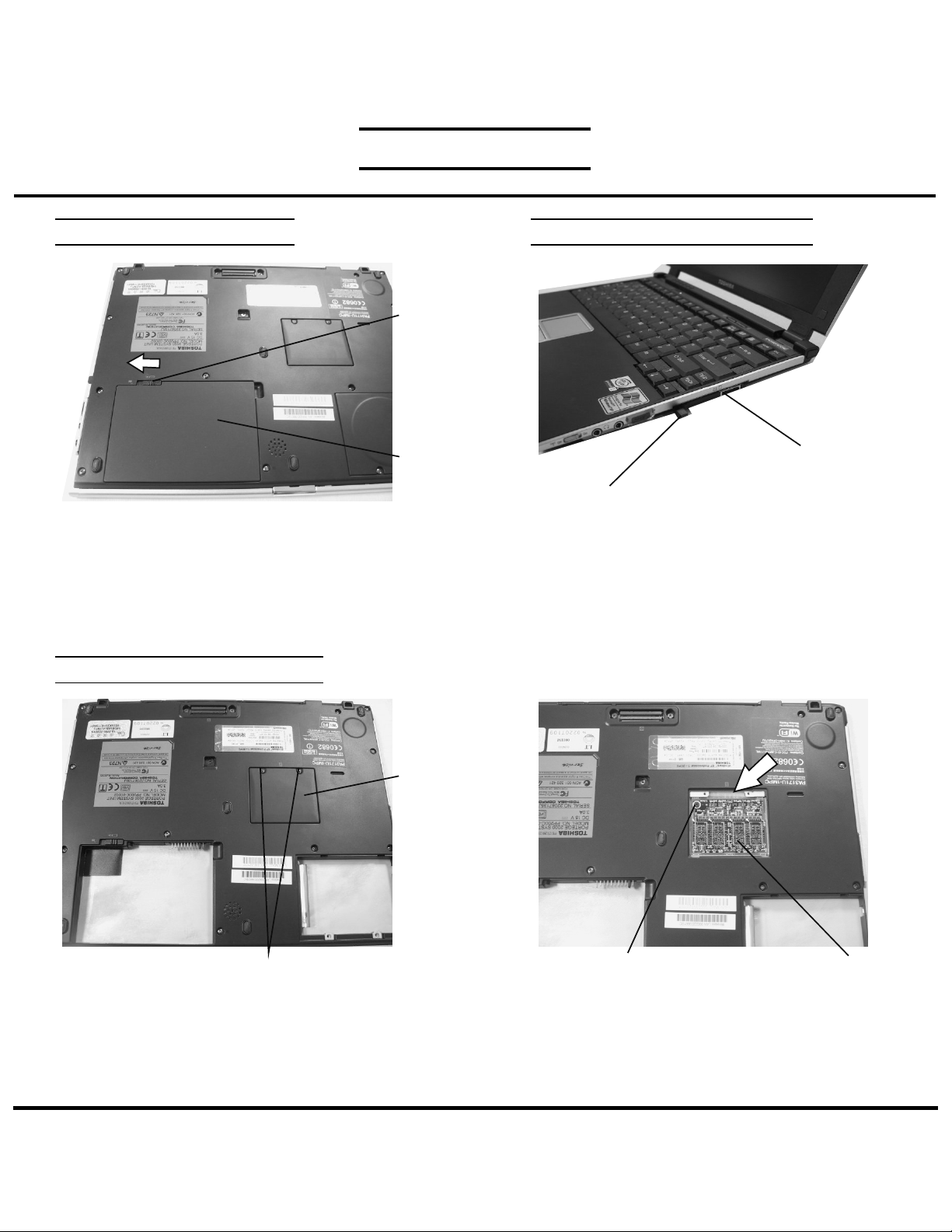
OPTIONAL PC CARD REMOVALBATTERY PACK REMOVAL
Battery
release
lever
Battery Pack
1. Turn the computer upside down as shown.
2. Slide the battery release lever to the left to release
the battery.
3. Lift out the battery.
MEMORY MEMORY REMOVAL
Memory
cover
PC card
Eject button
1. Press the eject button of the PCCard you want to
remove.
2. Press the extended eject button to pop the PC card
out.
3. Grasp the PC card and remove it.
Note: Before removing any PC Card device, make
sure it is “STOPPED” in the PC Card manager.
M2x2.5 black screws
1. Turn the computer upside down.
2. Remove two M2x2.5 black screws securing the memory
cover.
TOSHIBA
Tough Enough for Today’s World.
M2x3 black flat head screw
3. Remove one M2x3 black flat head screw securing
the memory module.
4. Disconnect the memory module from the top side
as shown by the arrow above.
Memory module
Page 4

FIELD REPLACEABLE UNIT DOCUMENTATION
TM
Portege
P2000 Series
HDD REMOVAL
HDD cover
M2x4 black screws
1. Turn the computer upside down.
2. Remove two M2x4 black screws securing the
HDD cover and lift it out.
HDD REMOVAL
HDD pad
HDD rubber holder
5. Remove the HDD rubber holder and the HDD pad.
HDD connector
3. Lift up the rubber handle and hold the HDD assembly
as shown above.
4. Disconnect the HDD assembly from the
HDD connector.
CAUTION:
KEYBOARD REMOVAL
1. Turn the computer upside down.
2. Remove one M2x3 black flat head screw securing
the keyboard.
Be very careful not to press on the TOP or
BOTTOM of the HDD. Pressure can destroy
data or damage the drive.
M2x3 black flat head screw
HDD assembly
TOSHIBA
Tough Enough for Today’s World.
Page 5

FIELD REPLACEABLE UNIT DOCUMENTATION
TM
Portege
P2000 Series
KEYBOARD REMOVAL
Latch
Keyboard
holder
3. Unlatch the keyboard holder at the top of the keyboard.
KEYBOARD REMOVAL
PJ445
Keyboard
Keyboard cable
5. Lift up the keyboard and lay it on the palm rest.
6. Disconnect the keyboard cable from PJ445 and lift out
the keyboard.
M2x3 silver flat head screws
4. Remove two M2x3 silver flat head screws securing
the keyboard.
TOP COVER REMOVAL
M2.5x6 black flat head screws
M2x6
black
screws
Rubber cover/M2x4 brass screw
1. Turn the computer upside down.
2. Remove the rubber cover close to the HDD slot
and remove one M2x4 brass screw.
2. Remove the following screws from the bottom cover:
- 9 M2x6 black screws
- 2 M2.5x6 black flat head screws
- 2 M2x4 black screws and 1 M2x4 brass screw
M2x4
black
screws
TOSHIBA
Tough Enough for Today’s World.
Page 6

FIELD REPLACEABLE UNIT DOCUMENTATION
TM
Portege
P2000 Series
TOP COVER REMOVAL
Power button/ LED board cable
PJ7
Internet/In
Touch buttons
cable
PJ8
Flexible
PWB
Touch Pad cable
3. Turn the computer right side up and open the display.
4. Disconnect the following cables by carefully lifting the lever
using from the PCB:
- Touch Pad cable from PJ334
- Flexible PWB from PJ9
- Internet/ In-Touch Buttons cable from PJ8
- Power Button/ LED board cable from PJ7
PJ334 PJ9
MINI PCI CARD REMOVAL
Top cover
M2x4 brass screws
5. Remove six M2x4 brass screws securing the top
cover.
6. Separate the top cover from the bottom cover.
White mini coax
Mini PCIcard
interface
adaptor
Wireless LAN card
1. Disconnect the Mini PCI card interface adaptor from the
system board.
2. Carefully lift up the Mini PCI card interface adaptor and
turn it over as shown on the next picture.
TOSHIBA
Tough Enough for Today’s World.
Mini PCI
connector
clips
Black mini coax
3. Disconnect the black and white mini coax from the
Mini PCI wireless LAN card.
4. Spread the mini PCI connector clips and pull the
wireless LAN card out of the connector about
30 degrees.
Page 7

FIELD REPLACEABLE UNIT DOCUMENTATION
TM
Portege
P2000 Series
RTC REMOVAL SPEAKER REMOVAL
Glass Tape
PJ10
RTC battery
PJ790
1. Peel off two strips of glass tape securing the RTC cable.
2. Disconnect the RTC harness from PJ790 and lift it out.
MODEM BOARD REMOVAL
1. Disconnect the modem harness from the modem board.
2. Remove two M2x4 brass screws securing the modem
board to the HDD/Modem interface board.
3. Disconnect the modem board from PJ3 on the
HDD/modem board
RTC harness
Modem
board
Modem
harness
HDD/modem
interface
board
M2x4 brass screws
Speaker harness
1. Disconnect the speaker harness from PJ10 on
the system board.
2. Lift out the speaker and separate the rubber
holder.
SOUND JACK BOARD REMOVAL
Guide pins
1. Lift up the sound jack board to free it from the
guide pins and pull it out.
2. Turn the board over as shown on the next picture.
Speaker
Sound jack board
Rubber holder
TOSHIBA
Tough Enough for Today’s World.
Page 8

FIELD REPLACEABLE UNIT DOCUMENTATION
TM
Portege
P2000 Series
SOUND JACK BOARD REMOVAL
Sound jack
cable
PJ999
3. Disconnect the sound jack cable from PJ999 on the
sound jack board.
4. Lift out the sound jack board.
Sound jack board
SYSTEM BOARD REMOVAL
LAN
harness
PJ352
SYSTEM BOARD REMOVAL
Glass tape
1. Peel off the glass tapes securing the modem
harness and the LAN harness.
2. Disconnect the LAN harness from PJ352 on the
system board.
3. Disconnect the LCD/FL harness from PJ34 and
PJ35 on the system board.
PJ34PJ35
LCD/FLharness
M2x4 brass
flat head
screws
M2x4 brass flat head screws
4. Remove two M2x4 flat head brass screws securing
the system board.
5. Remove two M2x4 brass screws securing the
PC card slots.
6. Lift out the system board.
System board
TOSHIBA
Tough Enough for Today’s World.
PJ3
PC card slots
PJ11
HDD/modem interface cable
7. Disconnect the PC card slots from PJ11 on the system
board.
8. Disconnect the HDD/modem interface cable from PJ3
on the system board.
9. Remove two cool sheets on the top side of the system
board.
Page 9

FIELD REPLACEABLE UNIT DOCUMENTATION
TM
Portege
P2000 Series
TOUCH PAD REMOVAL
Touch pad board
Touc pad/
Membrane
cable
RTC/
Speaker
holder
copper tape
LCD latch assy
1. Remove the RTC/Speaker holder.
2. Remove one M2x4brass screw securing the LCD
latch assembly and lift it out.
3. Disconnect the Touch pad/ Membrane cable from
the touch pad board.
M2x4 brass screws
Touch pad bracket
1. Carefully peel off the copper tape.
2. Remove four M2x3 silver flat head screws securing
the Touch pad assembly.
3. Lift out the touch pad assembly.
4. Separate the touch pad board from the touch pad
bracket.
M2x3 silver flat head screws
TOSHIBA
Tough Enough for Today’s World.
Page 10

FIELD REPLACEABLE UNIT DOCUMENTATION
TM
Portege
P2000 Series
DISPLAY MASK REMOVAL
LCD cushions
LCD module
Display mask
LCD mask seals
1. Remove one LCD cushions and six LCD mask seals
using a pair of fine-tipped tweezers.
2. Remove one M2x3 black flat head screw and
six M2x3 silver flat head screws securing the display
mask.
3. Lift out the display mask.
FL INVERTER AND LCD REMOVAL
M2x3 silver
Flat head
screw
LCD cable
1. Remove one M2x3 silver flat head screw securing
the FL inverter board.
2. Lift up the FL inverter board and disconnect the
FL cable from CN2 and the FL inverter cable
from CN1.
3. Carefully rotate out the top of the LCD module
enough to access the LCD/FL cable..
4. Disconnect the LCD/FL cable and lift it out.
FL inverter cable
LCD module
FL
inverter
board
FL cable
TOSHIBA
Tough Enough for Today’s World.
 Loading...