

Page 1

Toshiba Personal Computer
PORTÉGÉ M700
PORTÉGÉ M750
Maintenance Manual
TOSHIBA CORPORATION
3G & SmartCard (Rev B)
Degitizer utility(Rev C)
M750 (Rev D)
File Number 960-661
First Edition
[CONFIDENTIAL]
Page 2

Copyright
© 2007 by Toshiba Corporation. All rights reserved. Under the copyright laws, this manual
cannot be reproduced in any form without the prior written permission of Toshiba. No patent
liability is assumed with respect to the use of the information contained herein.
Toshiba Personal Computer PORTÉGÉ M700 Maintenance Manual
First edition Nov 2007
Rev B edition Feb 2008
Rev C edition May 2008
Rev D edition Sep 2008
Disclaimer
The information presented in this manual has been reviewed and validated for accuracy. The
included set of instructions and descriptions are accurate for the PORTÉGÉ R50 0 at the time
of this manual’s production. However, succeeding computers and manuals are subject to
change without notice. Therefore, Toshiba assumes no liability for damages incurred
directly or indirectly from errors, omissions, or discrepancies between any succeeding
product and this manual.
Trademarks
IBM is a registered trademark and IBM PC is a trademark of International Business
Machines Corporation.
Intel, Intel SpeedStep, Intel Core, Celeron and Centrino are trademarks or registered
trademarks of Intel Corporation or its subsidiaries in the United States and other
countries/regions.
Windows and Microsoft are registered trademarks of Microsoft Corporation.
Photo CD is a trademark of Eastman Kodak.
Bluetooth is a trademark owned by its proprietor and used by TOSHIBA under license.
i.LINK is a trademark of Sony Corporation.
ii [CONFIDENTIAL] PORTÉGÉ M700/M750 Maintenance Manual (960-661)
Page 3
Preface
This maintenance manual describes how to perform hardware service maintenance for the
Toshiba Personal Computer PORTÉGÉ M700/M750.
The procedures described in this manual are intended to help service technicians isolate
faulty Field Replaceable Units (FRUs) and replace them in the field.
SAFETY PRECAUTIONS
Four types of messages are used in this manual to bring important information to your
attention. Each of these messages will be italicized and identified as shown below.
DANGER: “Danger” indicates the existence of a hazard that could result in death or
serious bodily injury, if the safety instruction is not observed.
WARNING: “Warning” indicates the existence of a hazard that could result in bodily
injury, if the safety instruction is not observed.
CAUTION: “Caution” indicates the existence of a hazard that could result in property
damage, if the safety instruction is not observed.
NOTE: “Note” contains general information that relates to your safe maintenance
service.
Improper repair of the computer may result in safety hazards. Toshiba requires service
technicians and authorized dealers or service providers to ensure the following safety
precautions are adhered to strictly.
Be sure to fasten screws securely with the right screwdriver. If a screw is not fully
fastened, it could come loose, creating a danger of a short circuit, which could cause
overheating, smoke or fire.
If you replace the battery pack or RTC battery, be sure to use only the same model
battery or an equivalent battery recommended by Toshiba. Installation of the wrong
battery can cause the battery to explode.
PORTÉGÉ M700/M750 Maintenance Manual (960-661) [CONFIDENTIAL] iii
Page 4

The manual is divided into the following parts:
Chapter 1 Hardware Overview describes the T PORTÉGÉ M700/M750. system
unit and each FRU.
Chapter 2 Troubleshooting Procedures explains how to diagnose and resolve
FRU problems.
Chapter 3 Test and Diagnostics describes how to perform test and diagnostic
operations for maintenance servic e.
Chapter 4 Replacement Procedures describes the removal and replacement of the
FRUs.
Appendices The appendices describe the following:
Handling the LCD module
Board layout
Pin assignments
Keyboard scan/character codes
Key layout
Wiring diagrams
BIOS rewrite procedures
EC/KBC rewrite procedures
Reliability
iv [CONFIDENTIAL] PORTÉGÉ M700/M750 Maintenance Manual (960-661)
Page 5

Conventions
This manual uses the following formats to describe, identify, and highlight terms and
operating procedures.
Acronyms
On the first appearance and whenever necessary for clarification acronyms are enclosed in
parentheses following their definition. For example:
Read Only Memory (ROM)
Keys
Keys are used in the text to describe many operations. The key top symbol as it appears on
the keyboard is printed in boldface type.
Key operation
Some operations require you to simultaneously use two or more keys. We identify such
operations by the key top symbols separated by a plus (+) sign. For example, Ctrl + Pause
(Break) means you must hold down Ctrl and at the same t i me press Pause (Break). If
three keys are used, hold down the first two and at the same time press the third.
User input
Text that you are instructed to type in is shown in the boldface type below:
DISKCOPY A: B:
The display
Text generated by the computer that appears on its display is presented in the type face
below:
Format complete
System transferred
PORTÉGÉ M700/M750 Maintenance Manual (960-661) [CONFIDENTIAL] v
Page 6

Table of Contents
Chapter 1 Hardware Overview
1.1 Features......................................................................................................................1-1
1.2 System Unit Block Diagram......................................................................................1-9
1.3 3.5-inch Floppy Disk Drive (USB External) ...........................................................1-17
1.4 2.5-inch Hard Disk Drive.........................................................................................1-18
1.5 DVD-Super Multi Drive Optical Drive (ODD).......................................................1-20
1.6 Keyboard.................................................................................................................1- 23
1.7 TFT Color Display.................................................................................... ..............1- 24
1.8 Power Supply..........................................................................................................1- 25
1.9 Batteries ..................................................................................................................1- 28
1.10 AC Adaptor.............................................................................................................1- 31
Chapter 2 Troubleshooting Procedures
2.1 Troubleshooting.........................................................................................................2-1
2.2 Troubleshooting Flowchart........................................................................................2-2
2.3 Power Supply Troubleshooting..................................................................................2-7
2.4 System Board Troubleshooting................................................................................2-16
2.5 USB FDD Troubleshooting .....................................................................................2-30
2.6 HDD Troubleshooting .............................................................................................2-33
2.7 Keyboard and Dual point Troubleshooting ............................................................. 2-38
2.8 Touch pad Troubleshooting.....................................................................................2-40
2.9 Display Troubleshooting.......................................................................................... 2-41
2.10 Optical Drive Troubleshooting................................................................................2-44
2.11 LAN Troubleshooting..............................................................................................2-45
2.12 Bluetooth Troubleshooting ......................................................................................2-46
2.13 Wireless LAN Troubleshooting...............................................................................2-48
2.14 Modem Troubleshooting..........................................................................................2-50
2.15 Web camera Troubleshooting..................................................................................2-52
vi [CONFIDENTIAL] PORTÉGÉ M700/M750 Maintenance Manual (960-661)
Page 7

2.16 Tablet pen Troubleshooting.....................................................................................2-54
2.17 Touch screen Troubleshooting.................................................................................2-56
2.18 Sound Troubleshooting............................................................................................ 2-58
2.19 Bridge media Slot Troubleshooting.........................................................................2-60
2.20 Fingerprint sensor Troubleshooting......................................................................... 2-61
2.21 3G Troubleshooting ................................................................................................. 2-65
2.22 SmartCard Slot Troubleshooting .............................................................................2-67
Chapter 3 Tests and Diagnostics
3.1 The Diagnostic Test.......................................................................... .. .......................3-1
3.2 Executing the Diagnostic Test...................................................................................3-5
3.3 Setting of the hardware configuration .....................................................................3-10
3.4 Heatrun Test.............................................................................................................3-12
3.5 Subtest Names..........................................................................................................3-13
3.6 System Test..............................................................................................................3-15
3.7 Memory Test............................................................................................................3-17
3.8 Keyboard Test..........................................................................................................3-18
3.9 Display Test.............................................................................................................3-19
3.10 Floppy Disk Test......................................................................................................3-22
3.11 Printer Test...............................................................................................................3-24
3.12 Async Test ...............................................................................................................3-26
3.13 Hard Disk Test.........................................................................................................3-27
3.14 Real Timer Test........................................................................................................3-30
3.15 NDP Test..................................................................................................................3-32
3.16 Expansion Test.........................................................................................................3-33
3.17 CD-ROM/DVD-ROM Test .....................................................................................3-35
3.18 Error Code and Error Status Names.........................................................................3-36
3.19 Hard Disk Test Detail Status ...................................................................................3-39
3.20 ONLY ONE TEST...................................................................................................3-41
3.21 Head Cleaning..........................................................................................................3-56
3.22 Log Utilities.............................................................................................................3-57
3.23 Running Test............................................................................................................3-59
PORTÉGÉ M700/M750 Maintenance Manual (960-661) [CONFIDENTIAL] vii
Page 8

3.24 Floppy Disk Drive Utilities......................................................................................3-60
3.25 System Configuration ..............................................................................................3-65
3.26 Wireless LAN Test Program (Intel-made b/g, a/b/g Setting up of REF PC)........ 3-67
3.27 Wireless LAN Test Program on DUT PC(Intel-made )...........................................3-72
3.28 LAN/Modem/Bluetooth/IEEE1394 Test Program .................................................. 3-80
3.29 Sound Test program.................................................................................................3-87
3.30 3G Test program....................................... .. ................................... ..........................3-87
3.31 BIOS SETUP ...........................................................................................................3-88
Chapter 4 Replacement Procedures
4.1 Overview...................................................................................................................4-1
4.2 Battery pack............................................................................................................4-10
4.3 PC card/Smart card/Bridge media ................................. ... .................................. ... .4-12
4.4 Tablet PC pen..........................................................................................................4-15
4.5 Reserve pen case.....................................................................................................4-16
4.6 HDD........................................................................................................................4-17
4.7 Slim select bay module...........................................................................................4-21
4.8 Memory module (slot B).........................................................................................4-25
4.9 Fan hood..................................................................................................................4-28
4.10 Keyboard.................................................................................................................4-30
4.11 Memory module (slot A)........................................................................................4-34
4.12 Wireless LAN card/Robson card............................................................................4-37
4.13 3G card (3G model only)........................................................................................4-41
4.14 Base assembly and cover assembly............................................... ... .. ....................4-43
4.15 Slim select bay latch...............................................................................................4-47
4.16 Battery lock assembly.............................................................................................4-49
4.17 RTC battery.............................................................................................................4-50
4.18 Bluetooth module....................................................................................................4-52
4.19 Front panel..............................................................................................................4-54
4.20 Fan/Heat sink/CPU .................................................................................................4-55
4.21 System board...........................................................................................................4-61
4.22 HDD cable/Bluetooth cable ....................................................................................4-65
viii [CONFIDENTIAL] PORTÉGÉ M700/M750 Maintenance Manual (960-661)
Page 9

4.23 MDC .......................................................................................................................4-66
4.24 PC card slot............................................... .. ................................... .........................4-68
4.25 Smart card slot (Smart card model only)................................................................4-70
4.26 Battery cable holder................................................................................................4-72
4.27 Pen holder assembly ...............................................................................................4-73
4.28 Sensor board............................................................................................................4-74
4.29 Touch pad................................................................................................................4-75
4.30 Speaker....................................................................................................................4-79
4.31 Hinge assembly.......................................................................................................4-81
4.32 LCD unit/Touch panel/Digitizer.............................................................................4-85
4.33 Switch board/Fingerprint sensor board.................................................................4-106
4.34 Web camera board ................................................................................................4-108
4.35 Wireless antenna/Internal microphone/Web camera cable...................................4-109
Appendices
Appendix A Handling the LCD Module ...........................................................................A-1
Appendix B Board Layout ................................................................................................ B-1
Appendix C Pin Assignments............................................................................................ C-1
Appendix D Keyboard Scan/Character Codes..................................................................D-1
Appendix E Key Layout.....................................................................................................E-1
Appendix F Wiring Diagrams............................................................................................F-1
Appendix G BIOS rewrite Procedures..............................................................................G-1
Appendix H EC/KBC rewrite Procedures.........................................................................H-1
Appendix I Reliability........................................................................................................I-1
PORTÉGÉ M700/M750 Maintenance Manual (960-661) [CONFIDENTIAL] ix
Page 10

Chapter 1
Hardware Overview
[CONFIDENTIAL]
Page 11

1 Hardware Overview
1-ii [CONFIDENTIAL] PORTEGE M700/M750 Maintenance Manual (960-661)
Page 12

1 Hardware Overview
Chapter 1 Contents
1.1 Features.......................................................................................................................1-1
1.2 System Unit Block Diagram.......................................................................................1-9
1.3 3.5-inch Floppy Disk Drive (USB External)............................................................1-17
1.4 2.5-inch Hard Disk Drive .........................................................................................1-18
1.5 DVD-Super Multi Drive Optical Drive (ODD)........................................................1-20
1.6 Keyboard .................................................................................................................1- 23
1.7 TFT Color Display ..................................................................................................1- 24
1.8 Power Supply...........................................................................................................1- 25
1.9 Batteries...................................................................................................................1- 28
1.9.1 Main Battery ......................................................................................1- 28
1.9.2 Battery Charging Control...................................................................1- 29
1.9.3 RTC battery........................................................................................1- 30
1.10 AC Adaptor .............................................................................................................1- 31
PORTEGE M700/M750 Maintenance Manual (960-661) [CONFIDENTIAL] 1-iii
Page 13

1 Hardware Overview
Figures
Figure 1-1 Front of the computer....................................................................................1- 6
Figure 1-2 System unit configuration..............................................................................1- 7
Figure 1-3 System unit block diagram............................................................................1- 9
Figure 1-4 3.5-inch FDD (USB External).....................................................................1- 17
Figure 1-5 2.5-inch HDD ..............................................................................................1- 18
Figure 1-6 Keyboard .....................................................................................................1- 23
Figure 1-7 LCD module................................................................................................1- 24
Tables
Table 1-1 3.5-inch FDD specifications........................................................................1- 17
Table 1-2 2.5-inch HDD specifications .......................................................................1- 18
Table 1-3 DVD Super Multi drive specifications........................................................1- 20
Table 1-4 LCD module specifications.........................................................................1- 24
Table 1-5 ACPI State and Power line type..................................................................1- 25
Table 1-6 Power supply output rating..........................................................................1- 26
Table 1-7 Battery specifications ..................................................................................1- 28
Table 1-8 Time required for charges ...........................................................................1- 29
Table 1-9 RTC battery charging/data preservation time..............................................1- 30
Table 1-10 AC adapter specifications............................................................................1- 31
1-iv [CONFIDENTIAL] PORTEGE M700/M750 Maintenance Manual (960-661)
Page 14

1 Hardware Overview
1.1 Features
The Toshiba PORTEGE M700 ,M750 Personal Computer uses extensive Large Scale
Integration (LSI), and Complementary Metal-Oxide Semiconductor (CMOS) technology
extensively to provide compact size, minimum weight, low power usage and high reliability.
This computer incorporates the following features.
There some models and options. Refer to the Parts List for the configuration of each model
and options.
Microprocessor
The Toshiba PORTÉGÉ M700,M750 Personal Computer uses advanced Large Scale
Integration (LSI), and Complementary Metal-Oxide Semiconductor (CMOS) technology
extensively to provide compact size, minimum weight, low power usage and high reliability.
This computer incorporates the following features.
There are some models and options according to BTO system. Refer to the Parts List for the
configuration of each model and options.
Microprocessor
The PORTÉGÉ M700 computer is equipped with one of the following processors.
Intel ® Core
TM
2 Duo(Merom-4M or 2M)
T7800 (2.60GHz),T7700 (2.40GHz),T7500 (2.20GHz) L2=4MB
T7250 (2.00GHz) L2=2MB
The PORTÉGÉ M750 computer is equipped with one of the following processors.
Intel
®
Core
TM
2 Duo(Pennyn-6M or 3M,Merom-2M)
T9600 (2.80GHz),T9400 (2.53GHz), L2=6MB,FSB=1066MHz
T8600 (2.40GHz),T8400(2.26GHz), L2=3MB,FSB=1066MHz
T5870(2.00GHz),T5670(1.8GHz),L2=2MB,FSB=800MHz
Chipset
PORTÉGÉ M700
Equipped with Intel Crestline GM as North Bridge, Intel ICH8-M/ ICH8-8M-E as South
Bridge and Texas Instrument PCI8412 as Card Controller.
PORTEGE M700/M750 Maintenance Manual (960-661) [CONFIDENTIAL] 1-1
Page 15

1 Hardware Overview
PORTÉGÉ M750
Equipped with Intel Cantiga GM as North Bridge, Intel ICH9-M/-E as South Bridge and
Ricoh R5C847 as Card Controller.
VGA Controller
An internal Graphics Controller in North Bridge is used.
Memory
PORTÉGÉ M700
The computer comes with two PC4300(DDR2-533)/PC5300(DDR2-667) SO-DIMM
slots. Two memory modules of, 512MB, 1GB (1,024MB) or 2GB (2,048MB) can be
installed.
PORTÉGÉ M750
The computer comes with two PC6400(DDR2-800) SO-DIMM slots. Two memory
modules of, 1GB (1,024MB) , 2GB (2,048MB) or 4GB(4096MB) can be installed.
HDD
The computer has a 2.5-inch SATA HDD. The following capacities are available.
• 80/120/160/GB or 200/250GB
USB FDD
A 3.5-inch USB FDD accommodates 2HD (1.44MB) or 2DD (720KB) disks.
Optical Drive
PORTÉGÉ M700
A PATA I/F DVD Super Multi drive (double layer) can be installed.
PORTÉGÉ M750
A SATA I/F DVD Super Multi drive (double layer) can be installed.
Display
LCD : Built-in 12.1inch, 16M colors, WXGA(1280×800dots) thin type low
temperature poly-silicon TFT color display.
1-2 [CONFIDENTIAL] PORTEGE M700/M750 Maintenance Manual (960-661)
Page 16

1 Hardware Overview
External monitor : Supported via an RGB connector.
Digitizer
A digitizer is installed at the rear of LCD unit. The supplied tablet pen enables pen
computing.
Tablet pen / Reserve pen
The Tablet pen / Reserve pen can be used as a mouse by touching the display softly with
the pen tip. Tablet button on the side of the pen corresponds to the right click of the mouse.
Erase button on the pen tail can be used as an eraser depending on the application.
Touch screen
A touch screen is installed at the front of LCD unit.
Keyboard
An-easy-to-use 85(US)/87(UK)-key keyboard provides a numeric keypad overlay for fast
numeric data entry or for cursor and page control. The keyboard also includes two keys
that have special functions in Microsoft
®
Windows® Vista. It supports software that uses
a 101- or 102-key enhanced keyboard.
Touch pad
A Touch Pad and control buttons in the palm rest enable control of the on-screen pointer
and scrolling of windows.
Batteries
The computer has two batteries: a rechargeable Lithium-Ion main battery pack and RTC
battery (that backs up the Real Time Clock and CMOS memory).
Universal Serial Bus (USB2.0)
Three USB ports are provided. The ports comply with the USB2.0 standard, which
enables data transfer speeds 40 times faster than USB1.1 standard. USB1.1 is also
supported.
Note:
A power supply is always supplied to two USB ports on the left-hand side of a computer.
eSATA/USB combo
PORTEGE M700/M750 Maintenance Manual (960-661) [CONFIDENTIAL] 1-3
Page 17

1 Hardware Overview
One eSATA/USB combo port, which complies to. The USB 2.0 standard is provided. This
port has eSATA (External Serial ATA) function.
A power supply is always supplied to one USB ports on the left side of a computer.
IEEE 1394 port
The computer comes with one IEEE 1394 port. It enables high-speed data transfer
directly from external devices such as digital video cameras.
External monitor (RGB) port
The port enables connection of an external monitor, which is recognized automatically by
Video Electronics Standards Association (VESA) Display Data Channel (DDC) 2B
compatible functions.
PC card slot
A PC card slot are provided. The PC card slot (PCMCIA) accommodates one Type II
card or Express Slot(Choose only one) .
Bridge Media slot
One SD memory card/ SDIO card/Memory stick (PRO)/xD picture card/MultiMedia card
slot. Data can be read and written by inserting each media to the slot.
Fingerprint sensor
The computer is equipped with a fingerprint sensor and fingerprint authentication utility.
They enable only person who has registered his/her fingerprint to use the computer.
Docking interface port
The docking interface port enables connection of an optional Express Port Replicator. It
provides additional features as follows:
• RJ45 LAN jack
• External monitor port
• DC IN 15V jack
• Security lock slot
• Universal Serial Bus 2.0 port (four)
• DVI port
1-4 [CONFIDENTIAL] PORTEGE M700/M750 Maintenance Manual (960-661)
Page 18

1 Hardware Overview
Sound system
The sound system is equipped with the following features:
• speakers
• Volume control
• Stereo headphone jack
• External microphone jack
• Built-in microphone
Internal modem
The computer contains a MDC, enabling data and fax communication. It supports ITU-T
V.90 (V.92). The transfer rates are 56 Kbps for data reception, 33.6 Kbps for data
transmission, and 14,400 bps for fax transmission. However, the actual speed depends on
the line quality. The RJ11 modem jack is used to accommodate a telephone line. Both of
V.90 and V.92 are supported only in USA, Canada and Australia. Only V.90 is available
in other regions.
Internal LAN
The computer is equipped with LAN circuits that support Gigabit Ethernet LAN (1000
megabits per second, 1000BASE-T). It also supports Wakeup on LAN (WOL), Magic
Packet and LED.
Wireless LAN
The computer is equipped with PCI-Ex MiniCard type wireless LAN board that supports
802.11 b/g, 802.11 a/b/g or 802.11 a/b/g/n in the PCI-Ex MiniCard slot. This function can
be switched on and off by a switch on the computer.
Bluetooth
PORTÉGÉ M700
The computer is equipped with Bluetooth (V2.0+EDR) communications standard enable
wireless connection between electronic devices such as computers and printers. It
supports wireless communication switch.
PORTÉGÉ M750
PORTEGE M700/M750 Maintenance Manual (960-661) [CONFIDENTIAL] 1-5
Page 19
1 Hardware Overview
The computer is equipped with Bluetooth (V2.1+EDR) communications standard enable
wireless connection between electronic devices such as computers and printers. It
supports wireless communication switch.
Switch/Button
The following switches and buttons are equipped.
- Power on switch
- Cross Function button
- ESC/Rotation button
- Windows-Security tablet button
- Wireless Assist button
- Wireless Presentation button
3G
The computer is equipped with PCI Express Mini Card type 3G card
SmartCard Slot (SmartCard model only )
This computer supports ISO7816-3 asynchronous cards (support protocols are T=0 and
T=1)with a working voltage of 5V.
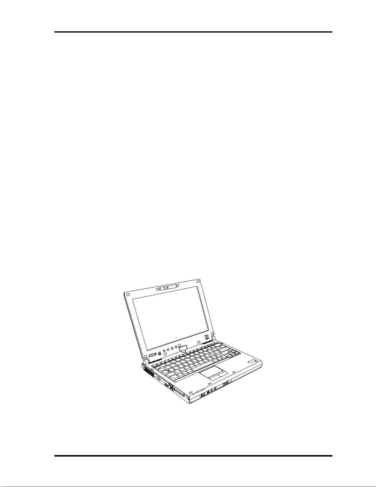
The front of the computer is shown in figure 1-1.
Figure 1-1 Front of the computer
1-6 [CONFIDENTIAL] PORTEGE M700/M750 Maintenance Manual (960-661)
Page 20
1 Hardware Overview
Rev B
The system unit configuration is shown in figure 1-2.
Figure 1-2-a M700 System unit configuration
PORTEGE M700/M750 Maintenance Manual (960-661) [CONFIDENTIAL] 1-7
Page 21
1 Hardware Overview
Figure 1-3-b M750 System unit configuration
1-8 [CONFIDENTIAL] PORTEGE M700/M750 Maintenance Manual (960-661)
Page 22
1 Hardware Overview
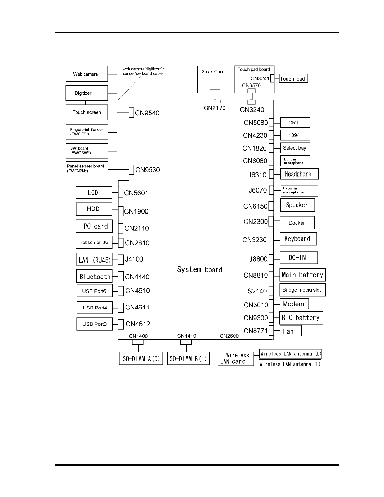
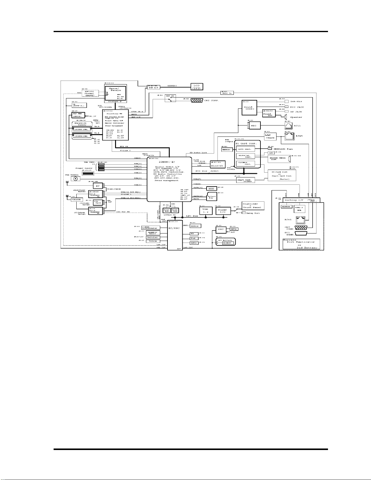
1.2 System Unit Block Diagram
Figure 1-3 is a block diagram of the system unit.
Figure 1-4-a M700 System unit block diagram
PORTEGE M700/M750 Maintenance Manual (960-661) [CONFIDENTIAL] 1-9
Page 23
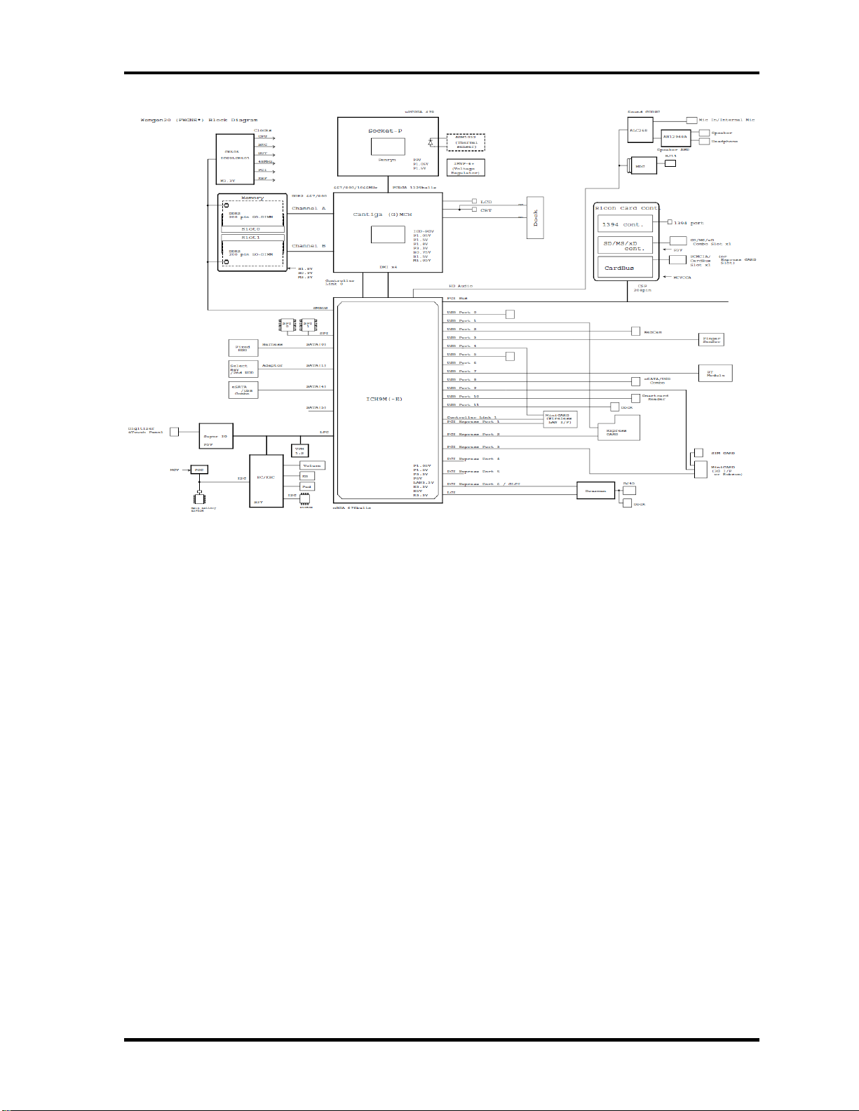
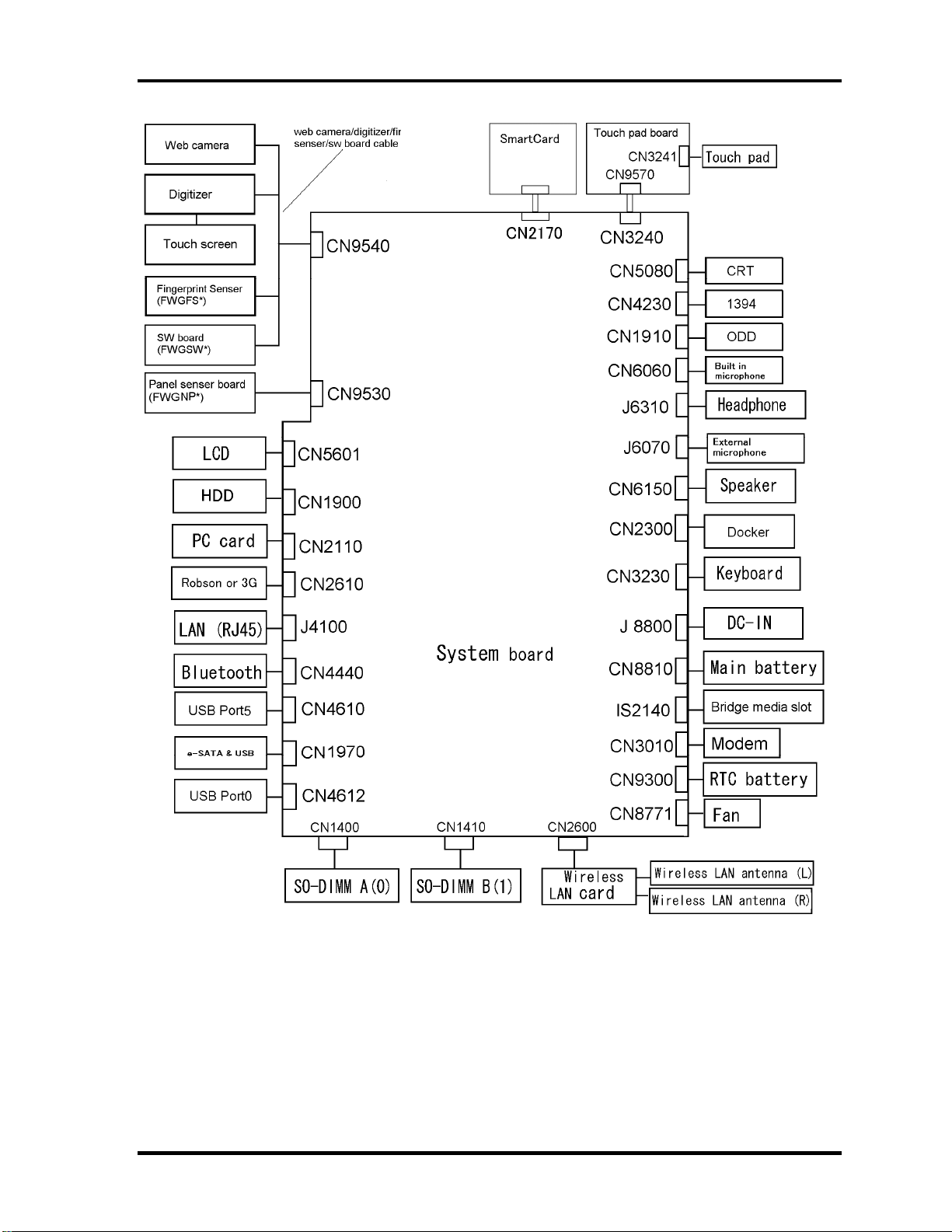
1 Hardware Overview
Figure 1-5-b M750 System unit block diagram
1-10 [CONFIDENTIAL] PORTEGE M700/M750 Maintenance Manual (960-661)
Page 24

1 Hardware Overview
The system unit is composed of the following major components:
Processor
PORTÉGÉ M700
Intel
®
Core
TM
2 Duo(Merom-4M or 2M)
T7800 (2.60GHz),T7700 (2.40GHz),T7500 (2.20GHz) L2=4MB (M700 only)
T7250 (2.00GHz) L2=2MB (M700 only)
T5870(2.00GHz),T5670(1.8GHz),L2=2MB (M750 only)
– Integrated L1 cache memory of 64KB (32KB +32KB)
– Integrated L2 cache memory of 4MB or 2MB
– Processor bus speed: 800MHz
– Core voltage: 1.05 V
– 478-pin Micro FC-PGA package
PORTÉGÉ M750
Intel ® Core
TM
2 Duo(Pennyn-6M or 3M,)
T9600 (2.80GHz),T9400 (2.53GHz), L2=6MB,FSB=1066MHz
T8600 (2.40GHz),T8400(2.26GHz), L2=3MB,FSB=1066MHz
– Integrated L1 cache memory of 64KB (32KB +32KB)
– Integrated L2 cache memory of 6MB or 3MB
– Processor bus speed: 1066MHz
– Core voltage: 1.05 V
– 478-pin Micro FC-PGA package
Memory
PORTÉGÉ M700
Tow memory slots capable of accepting DDR2-SDRAM 512MB, 1024MB or 2048MB
memory modules for a maximum of 4GB.
• 200-pin Small Outline DIMM
• 1.8V operation
• PC4300(DDR2-533)/PC5300(DDR2-667) support
PORTEGE M700/M750 Maintenance Manual (960-661) [CONFIDENTIAL] 1-11
Page 25

1 Hardware Overview
PORTÉGÉ M750
Tow memory slots capable of accepting DDR2-SDRAM 1024MB , 2048MB or 4096MB
memory modules for a maximum of 8GB.
• 200-pin Small Outline DIMM
• 1.8V operation
• PC6400(DDR2-800) support
North Bridge
PORTÉGÉ M700
• Intel 965:Crestline-GM
– Supports System Memory : DDR2-533/DDR2-667, 4GB(max)
– Meorom Processor System Bus Supports
– Internal Graphics Controller : Inter Generation 3.5 Accelerator
X3100(500Mhz)
– DMI(Direct Media Interface)
– Power management control (ACPI3.0 conformity)
– 1299-ball 3527×35×2.629(Max)mm FC-BGA package
–
PORTÉGÉ M750
• Intel GM45: Cantiga -GM
– Supports System Memory : DDR2-800, 8GB(max)
– Pennyn Processor System Bus Supports
– Internal Graphics Controller : Inter Generation 3.5 Accelerator
X3100(500Mhz)
– DMI(Direct Media Interface)
– Power management control (ACPI3.0 conformity)
– 1299-ball 3527×35×2.629(Max)mm FC-BGA package
South Bridge
PORTÉGÉ M700
• Intel ICH8-M/ ICH8-8M-E: (Intel 82801GBM)
– DMI(Direct Media Interface)
– PCI Express I/F (6ports)
1-12 [CONFIDENTIAL] PORTEGE M700/M750 Maintenance Manual (960-661)
Page 26

1 Hardware Overview
– PCI Bus I/F Rev2.3 (6 PCI REQ/GNT Pairs)
– Integrated Serial ATA Host Controller (3 Prots,300MB/S)
– Integrated IDE Controller (Ultra ATA 100/66/33)
– Intel High Definition controller (Azalia)
– USB 1.1/2.0 Controller 10 ports
– Built-in LAN controller (IEEE 802.3 compliance)
– Power Management (ACPI 3.0 compliance)
– SMBus2.0 controller
– SPI interface(BIOS)
– Low Pin Count (LPC) interface (EC/KBC, Super I/O)
– IRQ controller
– Serial Interrupt Function
– Suspend/Resume control
– Built –in RTC
– GPIO
– 672-ball 31×31×2.49(Max)mm BGA Package
–
PORTÉGÉ M750
• Intel ICH9-M/-E: (Intel 82801IBM)
– DMI(Direct Media Interface)
– PCI Express I/F (6ports)
– PCI Bus I/F Rev2.3 (6 PCI REQ/GNT Pairs)
– Integrated Serial ATA Host Controller (4 Prots,300MB/S)
– Integrated IDE Controller (Ultra ATA 100/66/33)
– Intel High Definition controller (Azalia)
– USB 1.1/2.0 Controller 12 ports
– Built-in LAN controller (IEEE 802.3 compliance)
– Power Management (ACPI 3.0 compliance)
– SMBus2.0 controller
– SPI interface(BIOS)
– Low Pin Count (LPC) interface (EC/KBC, Super I/O)
– IRQ controller
PORTEGE M700/M750 Maintenance Manual (960-661) [CONFIDENTIAL] 1-13
Page 27

1 Hardware Overview
– Serial Interrupt Function
– Suspend/Resume control
– Built –in RTC
– GPIO
– 672-ball 31×31×2.49(Max)mm BGA Package
Cardbus controller
PORTÉGÉ M700 (TI PCI8412ZHK)
− PCI Interface(PCI Rev.2.3)
− CardBus / Ultra media Controller (1 socket)
− IEEE1394 Controller(1 port)
− SD/MMC, MemoryStick, xD card Controller
− 216-ball 16×16×1.4(Max)mm BGA Package
PORTÉGÉ M750 (R5C847)
− PCI Interface(PCI Rev.3.0)
− CardBus / Ultra media Controller (1 socket)
− IEEE1394 Controller(1 port)
− SD/MMC, MemoryStick, xD card Controller
− 208-ball 16×16×1.4(Max)mm BGA Package
VGA
Graphics interface in North Bridge is used
Sound Controller
• HD Audio Link( Intel ICH8-M or ICH9-M built in)
• Real Tec ALC268
• Internal speaker
• volume control
• Supports VoIP
1-14 [CONFIDENTIAL] PORTEGE M700/M750 Maintenance Manual (960-661)
Page 28

1 Hardware Overview
• Stereo headphone jack
• External microphone jack
• Built-in microphone
Modem Controller
One MDC is used.
This controller has the following functions:
• One RJ11 port
• Azalia MDC
• V.92 (V.90) 56K Modem/FAX
• Ring wake up support
• Analog authoring is supported.
Internal LAN Controller
• Ethernet LAN (10 megabits per second, 10BASE-T), Fast Ethernet LAN (100
megabits per second, 100BASE-TX) or Gigabit Ethernet LAN (1000 megabits per
second, 1000BASE-T) is used.
– Gigabit Ethernet is supported.
– Intel Nineveh (82566MC / 82566MM)
– One RJ45 port
– Supports WOL
– Supports Magic Pocket
– AMT 2.6 is supported.
Wireless LAN
PORTÉGÉ M700
• One PCI-Ex MiniCard
Rev B
• Intel Golan b/g, Golan a/b/g, Intel , Kedron a/b/g/, Kedron a/b/g/n
• Supports Wireless Communication SW
PORTÉGÉ M700
• One PCI-Ex MiniCard
PORTEGE M700/M750 Maintenance Manual (960-661) [CONFIDENTIAL] 1-15
Page 29

1 Hardware Overview
• Intel Shirley Peak a/b/g/n or Echo Peak a/b/g/n +WiMAX .
Bluetooth
PORTÉGÉ M700
• V2.0 module
• Antenna built-in
PORTÉGÉ M750
• V2.1 module
• Antenna built-in
Sensor
• Thermal Sensor: One ADM1032ARMZ chip is used.
• LCD Sensor:.
• Acceleration Sensor
• Thermistor (Crestline-GM, memory, ODD, HDD, 3G:not used )
• Fingerprints sensor: Authen Tec maid
3G
o 3G card in the PCI Express Mini card slot
− Novatel EU870DT1 (EVDO for Verizon)
SmartCard Controller (SmartCard model only)
o OZ77CCR6LN
1-16 [CONFIDENTIAL] PORTEGE M700/M750 Maintenance Manual (960-661)
Page 30
1 Hardware Overview
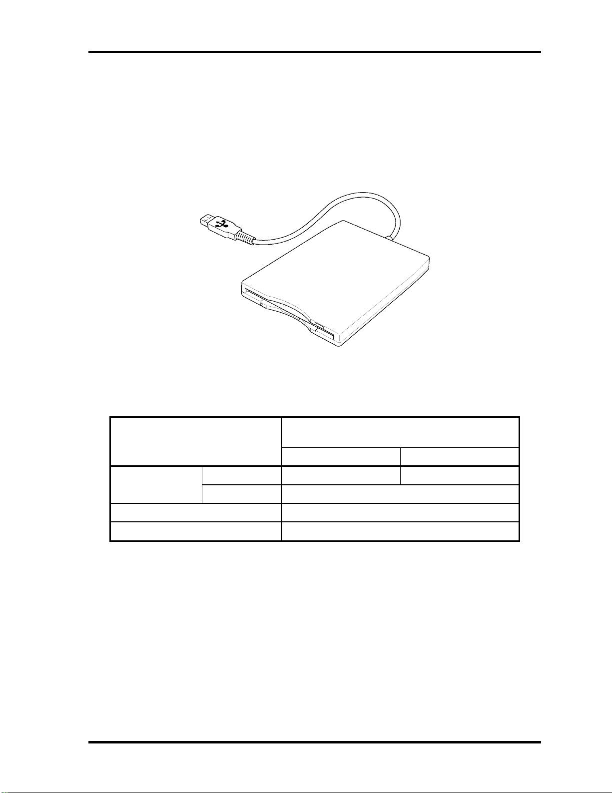
1.3 3.5-inch Floppy Disk Drive (USB External)
The 3.5-inch FDD is a thin, high-performance reliable drive that supports 720KB (formatted)
2DD and 1.44MB (formatted) 2HD disks.
The FDD is shown in figure 1-4. The specifications for the FDD are listed in Table 1-1.
Figure 1-6 3.5-inch FDD (USB External)
Table 1-1 3.5-inch FDD specifications
TEAC FD-05PUB-337
Items
720KB mode 1.44MB mode
FDD part 250K bits/second 500K bits/second Data transfer rate
USB Full speed mode (12M bits/second)
Disk rotation speed 300rpm
Track density 5.3 track/mm (135TPI)
(G8AC0000B320)
PORTEGE M700/M750 Maintenance Manual (960-661) [CONFIDENTIAL] 1-17
Page 31

1.4 2.5-inch Hard Disk Drive & SSD
The removable HDD is a random access non-volatile storage device. It has a non-removable
2.5-inch magnetic disk and mini-Winchester type magnetic heads.
The computer supports a 80GB, 120GB , 160GB , 200GB , 250GB HDD and 64GB,128GB
SSD.
The HDD is shown in figure 1-5. Specifications are listed in Table 1-2.
Figure 1-7 2.5-inch HDD
Table 1-2 2.5-inch HDD specifications s (1/5)
PORTÉGÉ M700
Item Specifications Maker Merker Code Parts Code
2.5"HDD
SATA
9.5mm
80GB
5400rpm
120GB
5400rpm
7200rpm
160GB
5400rpm
160GB
7200rpm
TOSHIBA MK8037GSX HDD2D61BZL01
HGST HTS542580K9SA00 G8BC0004D080
FUJITSU MHY2080BH G8BC0004E080
TOSHIBA MK1237GSX HDD2D62BZL01
HGST HTS542512K9SA00 G8BC0004D120
FUJITSU MHY2120BH G8BC0004E120
HGST HTS722012K9SA00 G8BC00046120 120GB
FUJITSU MHW2120BJ G8BC00047120
TOSHIBA MK1637GSX HDD2D60BZL01
HGST HTS542516K9SA00 G8BC0004D160
FUJITSU MHY2160BH G8BC0004E160
HGST HTS722016K9SA00 G8BC00046160
FUJITSU MHW2160BJ G8BC00047160
1-18 [CONFIDENTIAL] PORTEGE M700/M750 Maintenance Manual (960-661)
Page 32

1 Hardware Overview
PORTÉGÉ M750
Item Specifications Maker Merker Code Parts Code
2.5"HDD
SATA
9.5mm
SSD
HGST HTS543280L9SA00 G8BC00051080 80GB 5400rpm
FUJITSU MHZ2080BH G8BC00052081
or ***82
HGST HTS543212L9SA00 G8BC00051120 120GB 5400rpm
FUJITSU MHZ2120BH G8BC00052121
or ***22
HGST HTS543216L9SA00 G8BC00051160 160GB 5400rpm
FUJITSU MHZ2160BH G8BC00052161
or ***62
160GB 7200rpm HGST HTS723216L9A360 G8BC0005F160
200GB 7200rpm HGST HTS723220L9A360 G8BC0005F200
250GB 5400rpm
HGST HTS543225L9SA00 G8BC00051250
FUJITSU MHZ2250BH G8BC00052251
or ***52
Item Specifications Maker Merker Code Parts Code
64GB TOSHIBA THNS064GE4BBDC(T) G8BC00059640 2.5"SDD
SATA
9.5mm
128GB TOSHIBA THNS128GE4BBDC(T) G8BC00059120
PORTEGE M700/M750 Maintenance Manual (960-661) [CONFIDENTIAL] 1-19
Page 33

1 Hardware Overview
1.5 DVD-Super Multi Drive Optical Drive (ODD)
The DVD Super Multi drive accommodates either 12 cm (4.72-inch) or 8 cm (3.15-inch)
CD-ROM, DVD-ROM, CD-R, CD-RW, DVD-R, DVD+R, DVD-RW, DVD+RW, DVDRAM, DVD-R DL and DVD+R DL.
The specifications are listed in Table 1-3.
PORTÉGÉ M700
Table 1-3-a DVD Super Multi drive specifications
Specifications Item
I/F PATA PATA
Outline
dimensions
Data transfer speed (Read)
DVD-ROM
CD-ROM
Data transfer speed (Write)
CD-R
CD-RW
Multi speed CD-RW
High Speed CD-RW
Ultra Speed CD-RW
DVD-R
DVD-RW
DVD-R DL
DVD+R
DVD+R DL
DVD+RW
DVD-RAM
Width (mm) 128 (except protrusion) 128 (except protrusion)
Height (mm) 9.5 (except protrusion) 9.5 (except protrusion)
Depth (mm) 129 (except protrusion) 129 (except protrusion)
Mass (g)
Panasonic UJ-852
(G8CC00034A20)
142±5(Those with a bezel)
(Catalog spec)
Max. 8x CAV
Max. 24x CAV
(Catalog spec)
24 倍速(CLV)
4 倍速(CLV)
10 倍速(CLV)
16 倍速(CLV)
8 倍速(Zone CLV)
6 倍速(Zone CLV)
4 倍速(CLV)
8 倍速(Zone CLV)
Pioneer UJ-862
(G8CC0003ZA20)
105±5
<--
(Catalog spec)
24 倍速(CLV)
4 倍速(CLV)
10 倍速(CLV)
16 倍速(CLV)
8 倍速(Zone CLV)
6 倍速(Zone CLV)
6 倍速(CLV)
8 倍速(CAV)
4 倍速(CLV)
8 倍速(Zone CLV)
5 倍速(ZCLV) (4.7GB)
ATAPI Burst (MB/s)
PIO Mode
DMA Mode
Ultra DMA Mode
Data Buffer Capacity 2MB
16.6 (PIO MODE4)
16.6 (Multi Word Mode2)
33.3 (Ultra DMA Mode2)
6 倍速(Zone CLV)
8 倍速(Zone CLV)
5 倍速(Pertial CAV) (4.7GB)
1-20 [CONFIDENTIAL] PORTEGE M700/M750 Maintenance Manual (960-661)
Page 34

1 Hardware Overview
Access time: Random (ms)
CD-ROM
DVD-ROM
Supported Disks CD: CD/CD-ROM (12cm, 8cm), CD-R, CD-RW
DVD:DVD-ROM, DVD-R, DVD+R, DVD-RW DVD+RW,
DVD-RAM
Supported Formats CD: Sound CD, CD-ROM, CD-R, CD-RW,
Multi-session (Photo CD, CD extra)
DVD:DVD-ROM, DVD-Video, DVD-R, DVD-R DL, DVD+R,
DVD+R DL,
DVD-RW, DVD+RW, DVD-RAM
150msec typ.
180msec typ.
PORTÉGÉ M750
Table 1-3-b DVD Super Multi drive specifications
Specifications Item
Pioneer UJ-862 2ABTJ-M(G8CC000 4D120)
SATA
Outline
dimensions
I/F
Width (mm) 128 (except protrusion)
Height (mm) 9.5 (except protrusion)
150msec typ.
180msec typ.
Depth (mm) 129 (except protrusion)
Mass (g)
Data transfer speed (Read)
DVD-ROM
CD-ROM
Data transfer speed (Write)
CD-R
CD-RW
Multi speed CD-RW
High Speed CD-RW
Ultra Speed CD-RW
DVD-R
DVD-RW
DVD-R DL
DVD+R
DVD+R DL
DVD+RW
DVD-RAM
105±5
(Catalog spec)
Max. 8x CAV
Max. 24x CAV
(Catalog spec)
24 倍速(CLV)
4 倍速(CLV)
10 倍速(CLV)
16 倍速(CLV)
8 倍速(Zone CLV)
6 倍速(Zone CLV)
6 倍速(CLV)
8 倍速(CAV)
6 倍速(Zone CLV)
8 倍速(Zone CLV)
5 倍速(Pertial CAV) (4.7GB)
PORTEGE M700/M750 Maintenance Manual (960-661) [CONFIDENTIAL] 1-21
Page 35

1 Hardware Overview
ATAPI Burst (MB/s)
PIO Mode
DMA Mode
Ultra DMA Mode
Data Buffer Capacity 2MB
Access time: Random (ms)
CD-ROM
DVD-ROM
Supported Disks CD: CD/CD-ROM (12cm, 8cm), CD-R, CD-RW
DVD:DVD-ROM, DVD-R, DVD+R, DVD-RW DVD+RW,
DVD-RAM
Supported Formats CD: Sound CD, CD-ROM, CD-R, CD-RW,
Multi-session (Photo CD, CD extra)
DVD:DVD-ROM, DVD-Video, DVD-R, DVD-R DL, DVD+R,
DVD+R DL,
DVD-RW, DVD+RW, DVD-RAM
16.6 (PIO MODE4)
16.6 (Multi Word Mode2)
33.3 (Ultra DMA Mode2)
150msec typ.
180msec typ.
1-22 [CONFIDENTIAL] PORTEGE M700/M750 Maintenance Manual (960-661)
Page 36

1 Hardware Overview
1.6 Keyboard
The keyboard is mounted 85(US)/87(UK) keys that consist of character key and control key,
and in conformity with JIS. The keyboard is connected to membrane connector on the system
board and controlled by the keyboard controller.
Figure 1-6 is a view of the keyboard.
See Appendix E about a layout of the keyboard.
Figure 1-6 Keyboard
PORTEGE M700/M750 Maintenance Manual (960-661) [CONFIDENTIAL] 1-23
Page 37

1 Hardware Overview
1.7 TFT Color Display
The TFT color display consists of 12.1-inch WXGA LCD module.
The LCD module used for the TFT color display uses a white LED backlight as the light
source and can display a maximum of 16M colors with 1,200 x 800 resolution. The VGA in
North Bridge can control internal and external WXGA support displays simultaneously.
Figure 1-7 shows a view of the LCD module and Table 1-4 lists the specifications.
Figure 1-7 LCD module
Table 1-4 LCD module specifications
Item
12.1-inch WXGA TFT (TMD G33C0004J110)
Number of Dots 1,280(W) x 800(H)
Dot spacing (mm) 0.204(H) x 0.204(V)
Display range (mm) 261.12(H) x 163.2(V)
Specifications
1-24 [CONFIDENTIAL] PORTEGE M700/M750 Maintenance Manual (960-661)
Page 38

1 Hardware Overview
1.8 Power Supply
The power supply supplies many different voltages to the system board and performs the
following functions:
1. Judges that the DC power supply (AC adapter) is connected to the computer.
2. Detects DC output and circuit malfunctions.
3. Controls the battery icon, and DC IN icon.
4. Turns the battery charging system on and off and detects a fully charged battery.
5. Turns the power supply on and off.
6. Provides more accurate detection of a low battery.
7. Calculates the remaining battery capacity.
8. Controls the transmission of the status signal of the main battery.
Table 1-5 and 1-6 lists the power supply output specifications.
Table 1-5 ACPI State and Power line type
ACPI state S0 S3/S4/S5 S3 S4/S5 G3
M state M0
Wake On LAN Yes/No
P Power line On
M Power line On *1
B Power line On On On On
LAN-E Power
E Power line
S Power line On On On On On On
RTC Power
On
On
On
M1 Moff Moff -
- Yes No Yes No -
Off Off Off Off Off Off
Off Off Off Off Off
Off Off Off
On
On
On
On
On
On
Off
On
On
On
On
On
Off
*2
On
Off
Off
Off
On
*1 AMT supported model: On
AMT not supported model: off
*2 Wake up Enable : On
Wake up Disable : Off
PORTEGE M700/M750 Maintenance Manual (960-661) [CONFIDENTIAL] 1-25
Page 39

1 Hardware Overview
Table 1-6 Power supply output rating (1/2)
Device Name
Clock Gen
CPU
GMCH
Memory
SPD(Memory)
ICH8M(-E)
Slim Select Bay
SATA-HDD
Card Cont.
PC Card
Flash Media
Smart Card Reader
Wireless LAN
M-E3V 3.3
IR25M-E1V
PPV 0.55-1.35 P Power line
IR05-PIV 1.05 P Power line
IR5-PIV 1.5 P Power line
IR05-PIV 1.05 P Power line
IDG-PGV
IR25-PIV
IR5-PIV 1.5 P Power line
P3V
IR05M-EIV
IR25M-PIV
MOR9-BOV 0.9 B Power line
IR8-BIV 1.8 B Power line
OR9-BOV
MOR9-BOV 0.9
IR8-BIV 1.8 B Power line
M-E3V 3.3
IR05-PIV 1.05 P Power line
IR25-PIV
IR5-PIV 1.5 P Power line
P3V
P5V
E3V
LAN-E3V 3.3 LAN- E Power line
E5V
R3V
SB-P3V
SB-P5V
P3V
P5V
P3V
MCVCCA-PYV
IR5-PIV 1.5 P Power line Built-in regulator is not used.
MCVCCA-PYV
MCVPPA-PYV
FM-P3V
P3V
P5V
WLAN-PIV
WLAN-E3V
Voltage
[V]
1.25
1.05 P Power line
1.25 P Power line
3.3 P Power line
1.05
1.25
0.9
1.25 P Power line
3.3 P Power line
5 P Power line
3.3 E Power line
5 E Power line
2-3.5 RTC Power
P Power line
P Power line
3.3 P Power line
5
3.3 P Power line
3.3 P Power line
3.3 P Power line
5 P Power line
3.3 P Power line
3.3 P Power line
5 P Power line
1.5 P Power line
3.3 E Power line
Type
AMT
supported
M Power
line
M Power
line
M Power
line
M Power
line
B Power
line
B Power
line
M Power
line
P Power line
supported
AMT not
P Power
line
P Power
line
P Power
line
P Power
line
P Power
line
P Power
line
P Power
line
Remarks
It is distinguishable by whether parts are
carried in System board.
It is distinguishable by whether parts are
carried in System board.
It is distinguishable by whether parts are
carried in System board.
It is distinguishable by whether parts are
carried in System board.
It is distinguishable by whether parts are
carried in System board.
It is distinguishable by whether parts are
carried in System board.
It is distinguishable by whether parts are
carried in System board.
1-26 [CONFIDENTIAL] PORTEGE M700/M750 Maintenance Manual (960-661)
Page 40

1 Hardware Overview
Table 1-6 Power supply output rating (2/2)
Device Name
3G 3G-E3V 3.3 E Power line
SIM Card
Robson
SPI Flash Memory(for
BIOS)
MDC E3V
EC/KBC S3V
KB(LED)
Touch Pad
System LED
TPM Cont
Accelerometer
Super I/O
Fin9er Sensor
SPI Flash Mem.
(for Fin9er Sens.)
GbEPHY
LAN LED LNP-E3V
Bluetooth BT-P3V 3.3 P Power line
USB
DVI Transmitter
LCD PNL-P2V
LED Backlight LEDBL-PYV
CRT DDC-P5V
Sound Codec
Sound AMP
PSC MCV
FAN
UIMPWR-E3V
IR5-PIV 1.5 P Power line
P3V
LAN-E3V 3.3 LAN- E Power line
P5V
P5V
P5V
M5V
E3V
P3V
S3V
P3V
AT-E3V
OVCVDA-E3V
FS-E3V
VDDA-E3V
OVCVDA-E3V
LNPIRO-EIV
LNPIR8-EIV 1.8 LAN Power
LNP-E3V 3.3 LAN Power
USBOPS-E5V
USBIPS-E5V
2R5-P2V
P3V
P3V
A4R7-P4V
A4R7-P4V
SND-P5V
P5V
E5V
Voltage
[V]
3.3 E Power line
3.3 P Power line
3.3 E Power line
3.3 S Power line
5 P Power line
5 P Power line
5 P Power line
5 S Power line
3.3 E Power line
3.3 P Power line
3.3 S Power line
3.3 P Power line
3.3 E Power line
3.3 E Power line
3.3 E Power line
3.3 E Power line
3.3 E Power line
1.05
3.3 LAN Power
5 E Power line
5 E Power line
2.5 P Power line
3.3 P Power line
2.5 P Power line
5 P Power line
3.3 P Power line
4.7
4.7
5 P Power line
5 S Power line
5
5
Type
AMT
supported
LAN Power
P Power line
P Power line
P Power line
-
E Power
line
supported
AMT not
P Power
line
-
Remarks
It is distinguishable by whether parts are
carried in System board.
PORTEGE M700/M750 Maintenance Manual (960-661) [CONFIDENTIAL] 1-27
Page 41

1 Hardware Overview
1.9 Batteries
The computer has three types of batteries as follows:
Main battery pack
RTC battery
The battery specifications are listed in Table 1-7.
Table 1-7 Battery specifications
Battery name Material Output
voltage
Main battery
Slice Expansion Battery G71C0006K110/G71C0006K210
RTC battery GDM710000041 NiMH 2.4 V 15mAh
G71C0007M510/G71C0007M61
0
G71C0004S910/G71C0004SA10
Lithium-Ion 10.8 V
Lithium-Ion 10.8 V
Capacity
4,700 mAh
4,000 mAh
1.9.1 Main Battery
The removable main battery pack is the computer’s main power source when the AC adaptor
is not attached. The main battery maintains the state of the computer when the computer
enters in sleep mode.
1-28 [CONFIDENTIAL] PORTEGE M700/M750 Maintenance Manual (960-661)
Page 42

1 Hardware Overview
1.9.2 Battery Charging Control
Battery charging is controlled by a power supply microprocessor. The microprocessor
controls whether the charge is on or off and detects a full charge when the AC adaptor and
battery are attached to the computer. The system charges the battery.
Battery Charge
When the AC adaptor is attached, there are two types of charge: When the system is powered
off and when the system is powered on. Table 1-8 lists the charging time required for charges.
Table 1-8 Time required for charges
Battery type Power on (hours) Power off (hours)
Battery(4,700 mAh) About 3.0 to13.0 About 3.0
Slice Expansion Battery(4,000 mAh) About 3.0 to 9.5 About 2.5
NOTE: The time required when the system is powered on is affected by the amount of
power the system is consuming. Use of the fluorescent lamp and frequent disk
access diverts power and lengthens the charge time.
If any of the following occurs, the battery charge process stops.
1. The battery becomes fully charged.
2. The AC adaptor or battery is removed.
3. The battery or output voltage is abnormal.
Detection of full charge
A full charge is detected only when the battery is charging at charge. A full charge is
detected under any of the following conditions:
1. The current in the battery charging circuit drops under the predetermined limit.
2. The charging time exceeds the fixed limit.
PORTEGE M700/M750 Maintenance Manual (960-661) [CONFIDENTIAL] 1-29
Page 43

1 Hardware Overview
1.9.3 RTC battery
The RTC battery provides power to keep the current date, time and other setup information
in memory while the computer is turned off. Table 1-9 lists the charging time and data
preservation period of the RTC battery.
Table 1-9 RTC battery charging/data preservation time
Status Time
Charging Time (power on) 24 hours
Data preservation period (full charge) 30 days
1-30 [CONFIDENTIAL] PORTEGE M700/M750 Maintenance Manual (960-661)
Page 44

1 Hardware Overview
1.10 AC Adapter
The AC adapter is also used to charge the battery.
Table 1-10 lists the AC adapter specifications.
Table 1-10 AC adapter specifications
Parameter Specification
G71C0006R210 (3-pin) / G71C0006Q210 (2-pin)
Power 75W
Input voltage 100V/240V
Input frequency 50Hz to 60Hz
Input current 5.0A or less (100V-240V 4Aload)
Output voltage 15V
Output current 0A to 5A (At constant voltage mode)
PORTEGE M700/M750 Maintenance Manual (960-661) [CONFIDENTIAL] 1-31
Page 45

1 Hardware Overview
1-32 [CONFIDENTIAL] PORTEGE M700/M750 Maintenance Manual (960-661)
Page 46

Wengen20 (FWGNS*) Block Diagram
Digitizer
&Touch Panel
MCV
PSC
Main Battery
E2PROM
Super IO
P3V
CK505
ICS9LPR501
M3.3V
DDR2
200 pin SO-DIMM
DDR2
200 pin SO-DIMM
Fixed
HDD
Select
Bay
/2nd HDD
eSATA
/USB
Combo
Memory
Slot0
Slot1
I2C
Clocks
CPU
SRC
DOT
48MHz
PCI
REF
EC/KBC
S3V
Harness
Adaptor
SPI
0
I2C
DDR2 667/800
Channel A
Channel B
B1.8V
B0.9V
M3.3V
SPI
1
SATA[0]
SATA[1]
SATA[4]
SATA[5]
TPM
1.2
Volume
KB
Pad
E2PROM
SMBUS
Controller
Link 0
SPI
LPC
667/800/1066MHz
Cantiga (G)MCH
mBGA 676balls
Socket-P
Penryn
DMI x4
ICH9M(-E)
uFCPGA 478
PPV
P1.05V
P1.5V
FCBGA 1329balls
IGD-PGV
P1.05V
P1.5V
P1.8V
P3.3V
B0.75V
B1.5V
M1.05V
P1.05V
P1.5V
P3.3V
P5V
LAN3.3V
E3.3V
E5V
R3.3V
ADM1032
(Thermal
senser)
IMVP-6+
(Voltage
Regulator)
LCD
CRT
HD Audio
PCI Bus
USB Port 0
USB Port 1
USB Port 2
USB Port 3
USB Port 4
USB Port 5
USB Port 6
USB Port 7
USB Port 8
USB Port 9
USB Port 10
USB Port 11
Controller Link 1
PCI Express Port 1
PCI Express Port 2
PCI Express Port 3
PCI Express Port 4
PCI Express Port 5
PCI Express Port 6 / GLCI
LCI
Sound CODEC
ALC268
MDC
CRT
DVI
Dock
Ricoh Card Cont.
1394 cont.
SD/MS/xD
cont.
AN12948A
Speaker AMP
RJ11
1394 port
P3V
CardBus
MCVCCA
CSP
208pin
WebCam
eSATA/USB
Combo
Smartcard
Reader
Express
CARD
Dock
RJ45
Dock
MiniCARD
(Wireless
LAN I/F)
Boazman
Mic In/Internal Mic
Speaker
Headphone
SD/MS/xD
Combo Slot x1
PCMCIA/
CardBus
Slot x1
Finger
Sensor
BT
Module
SIM CARD
MiniCARD
(3G I/F
or Robson)
(or
Express CARD
Slot)
Page 47

Chapter 2
Troubleshooting Procedures
[CONFIDENTIAL]
Page 48

2 Troubleshooting Procedures
2-ii [CONFIDENTIAL] PORTEGE M700/M750 Maintenance Manual (960-661)
Page 49

2 Troubleshooting Procedures
Chapter 2 Contents
2.1 Troubleshooting..........................................................................................................2-1
2.2 Troubleshooting Flowchart ........................................................................................2-2
2.3 Power Supply Troubleshooting ..................................................................................2-7
Procedure 1 Icons in the LCD Check...............................................................2-7
Procedure 2 Error Code Check ........................................................................2-8
Procedure 3 Connection Check......................................................................2-13
Procedure 4 Charge Check.............................................................................2-14
Procedure 5 Replacement Check....................................................................2-15
2.4 System Board Troubleshooting ................................................................................2-16
Procedure 1 Message Check ..........................................................................2-17
Procedure 2 Serial Port Check (Boot Mode)..................................................2-19
Procedure 3 Diagnostic Test Program Execution Check...............................2-28
Procedure 4 Replacement Check....................................................................2-29
2.5 USB FDD Troubleshooting......................................................................................2-30
Procedure 1 USB FDD Head Cleaning Check...............................................2-30
Procedure 2 Diagnostic Test Program Execution Check...............................2-31
Procedure 3 Connector Check ......................................................................2-32
2.6 HDD Troubleshooting..............................................................................................2-33
Procedure 1 Message Check ..........................................................................2-33
Procedure 2 Partition Check...........................................................................2-34
Procedure 3 Format Check.............................................................................2-35
Procedure 4 Diagnostic Test Program Execution Check...............................2-36
Procedure 5 Connector Check and Replacement Check................................2-37
2.7 Keyboard and Dual point Troubleshooting ..............................................................2-38
Procedure 1 Diagnostic Test Program Execution Check...............................2-38
Procedure 2 Connector Check and Replacement Check................................2-38
2.8 Touch pad Troubleshooting......................................................................................2-40
Procedure 1 Diagnostic Test Program Execution Check...............................2-40
Procedure 2 Connector Check and Replacement Check................................2-40
PORTEGE M700/M750 Maintenance Manual (960-661) [CONFIDENTIAL] 2-iii
Page 50

2 Troubleshooting Procedures
2.9 Display Troubleshooting..........................................................................................2-41
Procedure 1 Diagnostic Test Program Execution Check...............................2-41
Procedure 2 Connector Check and Replacement Check................................2-41
Procedure 3 Replacement Check....................................................................2-43
2.10 Optical Drive Troubleshooting.................................................................................2-44
Procedure 1 Diagnostic Test Program Execution Check...............................2-44
Procedure 2 Connector Check and Replacement Check................................2-44
2.11 LAN Troubleshooting ..............................................................................................2-45
Procedure 1 Diagnostic Test Program Execution Check...............................2-45
Procedure 2 Connector Check and Replacement Check................................2-45
2.12 Bluetooth Troubleshooting.......................................................................................2-46
Procedure 1 Diagnostic Test Program Execution Check...............................2-46
Procedure 2 Connection Check and Replacement Check..............................2-46
2.13 Wireless LAN Troubleshooting ...............................................................................2-48
Procedure 1 Transmitting-Receiving Check..................................................2-48
Procedure 2 Antenna Connection Check .......................................................2-48
Procedure 3 Replacement Check....................................................................2-49
2.14 Modem Troubleshooting..........................................................................................2-50
Procedure 1 Diagnostic Test Program Execution Check...............................2-50
Procedure 2 Connection Check and Replacement Check..............................2-50
2.15 Web camera Troubleshooting...................................................................................2-52
Procedure 1 Diagnostic Test Program Execution Check...............................2-52
Procedure 2 Connection Check and Replacement Check..............................2-52
2.16 Tablet pen Troubleshooting......................................................................................2-54
Procedure 1 Check on Windows Vist ............................................................2-54
Procedure 2 Tablet psn replacement Check...................................................2-54
Procedure 3 Connection Check and Replacement Check..............................2-55
2.17 Touch screen Troubleshooting.................................................................................2-56
Procedure 1 Check on Windows Vist ............................................................2-56
Procedure 3 Connection Check and Replacement Check..............................2-57
2-iv [CONFIDENTIAL] PORTEGE M700/M750 Maintenance Manual (960-661)
Page 51

2 Troubleshooting Procedures
2.18 Sound Troubleshooting ............................................................................................2-58
Procedure 1 Diagnostic Test Program Execution Check...............................2-58
Procedure 2 Connector Check........................................................................2-58
Procedure 3 Replacement Check....................................................................2-59
2.19 Bridge media Slot Troubleshooting..........................................................................2-60
Procedure 1 Check on Windows OS..............................................................2-60
Procedure 2 Connector Check and Replacement Check................................2-60
2.20 Fingerprint sensor Troubleshooting .........................................................................2-61
Procedure 1 Setting Windows Log-ON password .........................................2-62
Procedure 2 Registration of fingerprint..........................................................2-62
Procedure 3 Authentication of fingerprint .....................................................2-63
Procedure 4 Connector Check and Replacement Check................................2-64
2.21 3G Troubleshooting..................................................................................................2-65
Procedure 1 Transmitting-Receiving Check..................................................2-65
Procedure 2 Antenna Connection Check .......................................................2-66
Procedure 3 Replacement Check....................................................................2-66
2.22 SmartCard Slot Troubleshooting..............................................................................2-67
Procedure 1 Check on T&D...........................................................................2-67
Procedure 2 Connector Check and Replacement Check................................2-67
PORTEGE M700/M750 Maintenance Manual (960-661) [CONFIDENTIAL] 2-v
Page 52

2 Troubleshooting Procedures
Figures
Figure 2-1 Troubleshooting flowchart ..................................................................................2-3
Figure 2-2 Debug port (Boot mode) error status.................................................................2-19
Tables
Table 2-1 Battery icon..........................................................................................................2-7
Table 2-2 DC IN icon...........................................................................................................2-7
Table 2-3 Error code ............................................................................................................2-8
Table 2-4 Result code ........................................................................................................2-14
Table 2-5 Debug port (Boot mode) error status.................................................................2-21
Table 2-6 FDD error code and status.................................................................................2-31
Table 2-7 HDD error code and status ................................................................................2-36
2-vi [CONFIDENTIAL] PORTEGE M700/M750 Maintenance Manual (960-661)
Page 53

2 Troubleshooting Procedures
2
Rev B
2.1 Troubleshooting
Chapter 2 describes how to determine if a Field Replaceable Unit (FRU) in the computer is
causing the computer to malfunction. The FRUs covered are:
1. Power Supply 2. System Board 3. USB Floppy Disk Drive
4. Hard Disk Drive 5. Keyboard/Dual point 6. Touch pad
7. Display 8. Optical Drive 9. LAN
10. Bluetooth 11. Wireless LAN 12. Modem
13. Web camera 14. Tablet Pen 15. Touch screen
16. Sound 17. Bridge media 18. Fingerprint sensor
19. 3G 20. SmartCard Slot
The Diagnostics Disk operations are described in Chapter 3. Detailed Replacement
Procedures are given in Chapter 4, Replacement Procedures.
The following tools are necessary for implementing the troubleshooting procedures:
The following tools are necessary for implementing the Diagnostics procedures:
For tools required for executing the Test Program, refer to the Chapter3. For tools required
for disassembling/assembling, refer to the Chapter 4.
1. A set of tools for debugging port test (test cable, test board, RS-232C cross cable,
display, D port FD)
2. A PC with a serial port (for displaying debug port test result)
3. DOS system FD
4. An external CRT display(for Display trouble shooting)
5. A SD card(for SD card slot trouble shooting)
6. An external microphone(for Sound trouble shooting)
7. Headphone(for Sound trouble shooting)
PORTEGE M700/M750 Maintenance Manual (960-661) [CONFIDENTIAL] 2-1
Page 54

2 Troubleshooting Procedures
2.2 Troubleshooting Flowchart
Use the flowchart in Figure 2-1 as a guide for determining which FRU malfunctions. Before
going through the flowchart steps, check the following:
Ask the user if a password is registered and, if it is, ask him or her to enter the
password.
Make sure that Toshiba Windows is installed on the hard disk. Non-Toshiba
operating systems can cause the computer malfunction.
Make sure all optional equipment is removed from the computer.
Make sure the USB FDD and optical drive are empty.
2-2 [CONFIDENTIAL] PORTEGE M700/M750 Maintenance Manual (960-661)
Page 55

2 Troubleshooting Procedures
Figure 2-1 Troubleshooting flowchart (1/2)
PORTEGE M700/M750 Maintenance Manual (960-661) [CONFIDENTIAL] 2-3
Page 56

2 Troubleshooting Procedures
Figure 2-1 Troubleshooting flowchart (2/2)
2-4 [CONFIDENTIAL] PORTEGE M700/M750 Maintenance Manual (960-661)
Page 57

2 Troubleshooting Procedures
If the diagnostics program cannot detect an error, the problem may be intermittent. The
Running Test program should be executed several times to isolate the problem. Check the
Log Utilities function to confirm which diagnostic test detected an error, then perform the
appropriate troubleshooting procedures as follows:
1. If an error is detected on the system test, memory test, real tim er test, perform the
System Board Troubleshooting Procedures in Section 2.4.
2. If an error is detected on the floppy disk test, perform the USB FDD Troubleshooting
Procedures in Section 2.5.
3. If an error is detected on the hard disk test, perform the HDD Troubleshooting
Procedures in Section 2.6.
4. If an error is detected on the keyboard test, perform the Keyboard Troubleshooting
Procedures in Section 2.7.
5. If an error is detected on the keyboard test, perform the Touch pad Troubleshooting
Procedures in Section 2.8.
6. If an error is detected on the display test, perform the Display Troubleshooting
Procedures in Section 2.9.
7. If an error is detected on the CD-ROM/DVD-ROM test, perform the Optical Drive
Troubleshooting Procedures in Section 2.10.
8. If an error is detected on the LAN test, perform the LAN Troubleshooting Procedures
in Section 2.11.
9. If an error is detected on the Bluetooth test, perform the Bluetooth Troubleshooting
Procedures in Section 2.12.
10. If an error is detected on the Wireless LAN test, perform the Wireless LAN
Troubleshooting Procedures in Section 2.13
11. If an error is detected on the sound test, perform the Modem Troubleshooting
Procedures in Section 2.14.
12. If an error is detected on the sound test, perform the Web camera Troubleshooting
Procedures in Section 2.15
13. If an error is detected on the sound test, perform the Tablet Pen Troubleshooting
Procedures in Section 2.16
14. If an error is detected on the sound test, perform the Touch screen Troubleshooting
Procedures in Section 2.17
PORTEGE M700/M750 Maintenance Manual (960-661) [CONFIDENTIAL] 2-5
Page 58

2 Troubleshooting Procedures
Rev B
15. If an error is detected on the sound test, perform the Sound Troubleshooting
Procedures in Section 2.18
16. If an error is detected on Bridge Media, perform the Bridge Media slot
Troubleshooting Procedures in Section 2.19.
17. If an error is detected on Fingerprint sensor, perform the Fingerprint sensor
Troubleshooting Procedures in Section 2.20.
18. If an error is detected on 3G test, perform the 3G Troubleshooting Procedures in
Section 2.21
19. If an error is detected on SmartCard test, perform the SmartCard Slot
Troubleshooting Procedures in Section 2.22
2-6 [CONFIDENTIAL] PORTEGE M700/M750 Maintenance Manual (960-661)
Page 59

2 Troubleshooting Procedures
2.3 Power Supply Troubleshooting
The power supply controls many functions and components. To determine if the power
supply is functioning properly, start with Procedure 1 and continue with the other Procedures
as instructed. The procedures described in this section are:
Procedure 1: Icons in the LCD Check
Procedure 2: Error Code Check
Procedure 3: Connection Check
Procedure 4: Charge Check
Procedure 5: Replacement Check
Procedure 1 Icons in the LCD Check
The following Icons in the LCD indicate the power supply status:
Battery icon
DC IN icon
The power supply controller displays the power supply status through the Battery icon and
the DC IN icon in the LCD as listed in the tables below. To check the power supply status,
install a battery pack and connect an AC adaptor.
Table 2-1 Battery icon
Battery icon Power supply status
Lights orange Battery has been charging and AC adapter is connected.
Lights green Battery is fully charged and AC adapter is connected.
Flashes orange Battery charge is low. The AC adaptor must be connected to recharge
the battery.
Doesn’t light Any condition other than those above.
Table 2-2 DC IN icon
DC IN icon Power supply status
Lights green DC power is being supplied from the AC adapter.
Flashes orange There is a problem with the power supply.
Doesn’t light Any condition other than those above.
PORTEGE M700/M750 Maintenance Manual (960-661) [CONFIDENTIAL] 2-7
Page 60

2 Troubleshooting Procedures
Procedure 2 Error Code Check
If the power supply microprocessor detects a malfunction, it indicates the error code as
shown below.
The error code begins with the least significant digit.
Table 2-3 Error code
Error code Where Error occurs
1*h AC Adaptor
2*h 1st Battery
3*h 2nd Battery
4*h S3V output
5*h E5V output
6*h E3V output
7*h 1R5-E1V output
8*h 1R8-B1V output
9*h PPV output
A*h 1R05-P1V output
B*h 1R5-E1V output
C*h 1R8-B1V output
D*h PPV output
E*h 1R05-P1V output
F*h -
2-8 [CONFIDENTIAL] PORTEGE M700/M750 Maintenance Manual (960-661)
Page 61

2 Troubleshooting Procedures
Check 1 Compare the patterns in the hexadecimal error code to the tables below.
AC Adaptor
Error code Meaning
10h AC Adaptor output voltage is over 16.5V.
11h Express Port Replicator voltage is over 16.5V.
12h Current from the DC power supply is over 7.70A.
13h Current from the DC power supply is over 0.5A when there is no loa d.
14h The compensation value of [0A] is not within the limits from design
data (+/- 481mA).
1st Battery
Error code Meaning
22h 1st battery discharge current over 0.5A when there is no load.
23h 1st battery charge current is over 3.9A in charging.
2nd Battery
Error code Meaning
S3V output
Error code Meaning
40h S3V voltage is over 3.47V when the computer is powered on/off.
45h S3V voltage is under 3.14V in normal conditions.
46h S3V voltage is under 3.14V when the computer is booting up.
24h
25h 1st battery charge current is over 0.3A in not charging.
32h 2nd battery discharge current is over 0.5A when the re is no load.
33h 2nd battery charge current is over 3.5A in charging.
34h The compensation value of [0A] is not within the limits from design
35h 2nd battery charge current is over 0.3A in not charging.
The compensation value of [0A] is not within the limits from design
data (+/- 400mA).
data (+/- 400mA).
PORTEGE M700/M750 Maintenance Manual (960-661) [CONFIDENTIAL] 2-9
Page 62

2 Troubleshooting Procedures
E5V output
Error code Meaning
50h E5V voltage is over 6.00V when the computer is powered on/off.
51h E5V voltage is under 4.50V when the computer is po wered on.
52h E5V voltage is under 4.50V when the computer is bo oting up.
54h E5V voltage is under 4.50V when EV power is mai ntained and
OUTV1=EV is designated.
E3V output
Error code Meaning
60h E3V voltage is over 3.96V when the computer is powered on/off.
61h E3V voltage is under 2.81V when the computer is po wered on.
62h E3V voltage is under 2.81V when the computer is bo oting up.
64h E3V voltage is under 2.81 V when EV power is maintained.
1R5-E1V output
Error code Meaning
70h 1R5-E1V voltage is over 1.80V when the computer is powered on/off.
71h 1R5-E1V voltage is under 1.275V when the computer is powered on.
72h 1R5-E1V voltage is under 1.275V when the com puter is booting up.
74h 1R5-E1V voltage is under 4.50V when EV power is maintained and
1R8-B1V output
Error code Meaning
80h 1R8-B1V voltage is over 2.16V when the computer is powered on/off.
81h 1R8-B1V voltage is under 1.53V when the computer is powered on.
82h 1R8-B1V voltage is under 1.53V when the computer is booting up.
84h 1R8-B1V voltage is under 1.53V when EV power is maintained and
OUTV1=EV is designated.
OUTV4=EV is designated.
2-10 [CONFIDENTIAL] PORTEGE M700/M750 Maintenance Manual (960-661)
Page 63

2 Troubleshooting Procedures
PPV output
Error code Meaning
90h PPV voltage is over 1.80V when the computer is powered on/off.
91h PPV voltage is under 0.32V when the computer is powered on.
92h PPV voltage is under 0.32V when the computer is booting up.
1R05-P1V output
Error code Meaning
A0h 1R05-P1V voltage is over 1.26V when the computer is powered on/off.
A1h 1R05-P1V voltage is un der 0.89V when the computer is powered on.
A2h 1R05-P1V voltage is un der 0.89V when the computer is booting up.
1R5-E1V output
Error code Meaning
B0h 1R5-E1V voltage is over 1.80V when the computer is powered on/off.
B1h 1R5-E1V voltage is unde r 1.275V when the computer is powered on.
B2h 1R5-E1V voltage is unde r 1.275V when the computer is booting up.
B4h 1R5-E1V voltage is unde r 1.275V when EV power is maintained and
1R8-B1V output
Error code Meaning
C0h 1R8-B1V voltage is over 2.16V when the computer is powered on/off.
C1h 1R8-B1V voltage is under 1.53V when the computer is powered on.
C2h 1R8-B1V voltage is under 1.53V when the computer is booting up.
C4h 1R8-B1V voltage is under 1.53V when BV power is maintained and
PPV output
OUTV7=EV is designated.
OUTV8=BV is designated.
Error code Meaning
D0h PPV voltage is over 1.80V when the computer is powered on/off.
D1h PPV voltage is under 0.32V when the computer is powered on.
D2h PPV voltage is under 0.32V when the computer is booting up.
PORTEGE M700/M750 Maintenance Manual (960-661) [CONFIDENTIAL] 2-11
Page 64

2 Troubleshooting Procedures
1R05-P1V output
Error code Meaning
E0h 1R05-P1V voltage is over 1.26V when the computer is powered on/off.
E1h 1R05-P1V voltage is under 0.89V when the computer is powered on.
E2h 1R05-P1V voltage is under 0.89V when the computer is booting up.
Miscellaneous
Error code Meaning
F0h The sub clock does not oscillate.
Check 2 In the case of error code 10h or 12h:
Make sure the AC adaptor cord and AC power cord are firmly plugged into
the DC IN 15 V socket and wall outlet. If the cables are connected correctly,
go to the following step:
Connect a new AC adaptor and/or AC power cord, if necessary. If the error
still exists, go to Procedure 5.
Check 3 In the case of error code 2Xh:
Make sure the battery pack is correctly installed in the computer. If the
battery pack is correctly installed, go to the following step:
Replace the battery pack with a new one. If the error still exists, go to
Procedure 5.
Check 4 For any other error, go to Procedure 5.
2-12 [CONFIDENTIAL] PORTEGE M700/M750 Maintenance Manual (960-661)
Page 65

2 Troubleshooting Procedures
Procedure 3 Connection Check
The power supply wiring diagram is shown below:
Any of the connectors may be disconnected. Perform Check 1.
Check 1 Disconnect the AC power cord from the wall outlet. Check the power cable for
breaks. If the power cord is damaged, connect a new AC power cord. If there is
no damage, go to Check 2.
Check 2 Make sure the AC adaptor cord and AC power cord are firmly plugged into the
DC-IN jack socket and AC adaptor inlet/wall outlet, respectively. If these cables
are connected correctly, go to Check 3.
Check 3 Make sure the DC IN jack is firmly connected to the connector CN8800 on the
system board.
• If the DC IN jack is not firmly connected, go to Procedure 5.
• If it is connected, go to Check 4.
Check 4 Use a multimeter to make sure the AC adaptor output voltage is close to 15 V. If
the output is several percent lower than 15 V, go to Check 5. If the output is close
to 15 V, go to Check 6.
Check 5 Connect a new AC adaptor or AC power cord.
• If the DC IN icon does not light, go to Procedure 5.
• If the battery icon does not light, go to Check 6.
Check 6 Make sure the battery pack is installed in the computer correctly. If the battery is
properly installed and the battery icon still does not light, go to Procedure 4.
PORTEGE M700/M750 Maintenance Manual (960-661) [CONFIDENTIAL] 2-13
Page 66

2 Troubleshooting Procedures
Procedure 4 Charge Check
The power supply may not charge the battery pack. Perform the following procedures:
1. Reinstall the battery pack.
2. Attach the AC adaptor and turn on the power. If you cannot turn on the power, go to
Procedure 5.
3. Run the Diagnostic test, go to System test and execute subtest 04 (Quick charge)
described in Chapter 3.
4. When charge is complete, the diagnostics test displays the result code. Check the
result code against the table below and perform any necessary check.
Table 2-4 Result code
Result code Contents Check items
0 The battery is charging normally. Normal
1 The battery is fully charged. Normal
2 The AC adaptor is not attached. Check 1
3 The AC adaptor’s output voltage is not normal. Check 1
4 The battery is not installed. Check 2
5 The battery’s output voltage is not normal. Check 3
6 The battery’s temperature is not normal. Check 4
7 A bad battery is installed. Check 2
8 Any other problems. Check 5
Check 1 Make sure the AC adaptor and AC power cord are firmly plugged into the DC IN
socket and the wall outlet. If these cables are connected correctly, replace the AC
adaptor (and/or AC power cord, if necessary).
Check 2 Make sure the battery is properly installed. If the battery is properly installed, go
to Check 3.
Check 3 The battery pack may be completely discharged. Wait a few minutes to charge the
battery pack. If the battery pack is still not charged, go to Check 4.
Check 4 The battery’s temperature is too hot or cold. Return the temperature to a normal
operating condition. If the battery pack still is not charged, go to Check 5.
Check 5 Replace the battery pack with a new one. If the battery pack still is not charged,
go to Procedure 5.
2-14 [CONFIDENTIAL] PORTEGE M700/M750 Maintenance Manual (960-661)
Page 67

2 Troubleshooting Procedures
Procedure 5 Replacement Check
The system board processor module may be disconnected or damaged. Disassemble the
computer following the steps described in Chapter 4, Replacement Procedures. Check the
connection between the AC adaptor and system board and connection. After checking the
connections, perform the following Check 1:
Check 1 Replace the AC adaptor with a new one. If the AC adaptor is still not functioning
properly, perform Check 2.
Check 2 Replace the system board with a new one following the steps described in Chapter
4, Replacement Procedures.
PORTEGE M700/M750 Maintenance Manual (960-661) [CONFIDENTIAL] 2-15
Page 68

2 Troubleshooting Procedures
2.4 System Board Troubleshooting
This section describes how to determine if the system board and CPU are defective or not
functioning properly. Start with Procedure 1 and continue with the other procedures as
instructed.
The procedures described in this section are:
Procedure 1: Message Check
Procedure 2: Printer Port LED Check on Boot Mode
Procedure 3: Diagnostic Test Program Execution Check
Procedure 4: Replacement Check
2-16 [CONFIDENTIAL] PORTEGE M700/M750 Maintenance Manual (960-661)
Page 69

2 Troubleshooting Procedures
Procedure 1 Message Check
When the power is turned on, the system performs the Initial Reliability Test (IRT) installed
in the BIOS ROM. The IRT tests each IC on the system board and initializes it.
If an error message is shown on the display, perform Check 1.
If there is no error message, go to Procedure 2.
If DOS or Windows is properly loaded, go to Procedure 3.
Check 1 If one of the following error messages appears on the screen, press F1 as the
message instructs. These errors occur when the system configuration preserved in
the RTC memory (CMOS type memory) is not the same as the actual
configuration or when the data is lost.
If you press F1 as the message instructs, returns all system settings to their default
values. Then the system reboots.
If error message (b) appears often when the power is turned on, replace the RTC
battery. If any other error message displays, perform Check 2.
(a) *** Bad HDD type ***
Check system. Then press [F1] key ......
(b) *** Bad RTC battery ***
Check system. Then press [F1] key ......
(c) *** Bad configuration ***
Check system. Then press [F1] key ......
(d) *** Bad memory size ***
Check system. Then press [F1] key ......
(e) *** Bad time function ***
Check system. Then press [F1] key ......
(f) *** Bad check sum (CMOS) ***
Check system. Then press [F1] key ......
(g) *** Bad check sum (ROM) ***
Check system. Then press [F1] key ......
PORTEGE M700/M750 Maintenance Manual (960-661) [CONFIDENTIAL] 2-17
Page 70

2 Troubleshooting Procedures
Check 2 The IRT checks the system board. When the IRT detects an error, the system
stops or an error message appears.
If one of the following error messages (1) through (17), (22) or (23) appears, go to
Procedure 4.
If the error message (18) appears, go to the Keyboard Troubleshooting Procedures
in Section 2.7.
If the error message (19), (20) or (21) appears, go to the HDD Troubleshooting
Procedures in Section 2.6.
If the error message (21) appears, go to the Optical Drive Troubleshooting
Procedures in Section 2.9.
(1) PIT ERROR
(2) MEMORY REFRE SH ERROR
(3) TIMER CH.2 OUT ERROR
(4) CMOS CHECKSUM ERROR
(5) CMOS BAD BATTERY ERROR
(6) FIRST 64KB MEMORY ERROR
(7) FIRST 64KB MEMORY PARITY ERROR
(8) VRAM ERROR
(9) SYSTEM MEMORY ERROR
(10) SYSTEM MEMORY PARITY ERROR
(11) EXTENDED MEMORY ERROR
(12) EXTENDED MEMORY PARITY ERROR
(13) DMA PAGE REGISTER ERROR
(14) DMAC #1 ERROR
(15) DMAC #2 ERROR
(16) PIC #1 ERROR
(17) PIC #2 ERROR
(18) KBC ERROR
(19) HDC ERROR
(20) Built-in HDD ERROR
(21) Select Bay ERROR
(22) TIMER INTERRUPT ERROR
(23) RTC UPDATE ERROR
2-18 [CONFIDENTIAL] PORTEGE M700/M750 Maintenance Manual (960-661)
Page 71

2 Troubleshooting Procedures
Procedure 2 Debugging Port Check (Boot Mode)
Check the D port status by a serial port test. The tool for serial port test is shown below.
Figure 2-2 Debug port (Boot mode) error status
The test procedures are follows:
1. Make "W3400" of system board short-circuited with a wire. As for the position of
W3400, refer to Chapter 4 and Appendix B.
2. Connect the debug port test cable to the connector CN3400 of the system board. For
disassembling to connect the test cable, refer to Chapter 4.
3. Connect the debug port test cable and RS-232C cross-cable to the test board.
4. Connect the RS-232C Cross-cable to the PC that displays the test results.
PORTEGE M700/M750 Maintenance Manual (960-661) [CONFIDENTIAL] 2-19
Page 72

2 Troubleshooting Procedures
4. Boot the computer in DOS mode.
5. Execute GETDPORT.COM in the text menu in CPU REAL mode. (Insert the FD for
starting D port into FDD and input “FD starting drive:>dport”.)
The D port status is displayed in the following form;
5. When the D port status is FFFF (normal status), go to Procedure 4. When the D port
status falls into any other status than FFFF, go to Procedure 3.
6. Cancel short-circuit for W3400 after the end of a test.
2-20 [CONFIDENTIAL] PORTEGE M700/M750 Maintenance Manual (960-661)
Page 73

2 Troubleshooting Procedures
Table 2-5 Debug port error status (1/6)
D port
status
Inspection items Target device IC number
SystemBIOSBootblockprocessing
setup of CPU ,
Initialization of MCH ,
Initialization of ICH ,
EC access check,
setup of PIT,
Initialization of ICH and
Super I/O
BIOS ROM check,
F000
Problematic to BIOS
ROM data.
F001 EC/KBC rewrite check
F002 Initialization of KBC
CPU, MCH(Register)、
ICH(Register、PIT
Controller, MEM I/O),
EC/KBC(EC), BIOSROM,
EC/KBC(KBC)、
EC/KBC(EC, KBC)、
Super I/O
BIOSROM
BIOSROM
BIOSROM
IS1050 (CPU Socket)
IC1200 (MCH)
IC1600 (ICH)
IC3200 (EC/KBC)
IC3001, IC3002 (BIOS
ROM)
IC3400 (Super I/O)
IC3001, IC3002 (BIOS
ROM)
IC3200 (EC/KBC)
IC3001, IC3002 (BIOS
ROM)
IC3200 (EC/KBC)
IC3001, IC3002 (BIOS
ROM)
Initialization of EC
F003 Initialization failure of EC
F004
Initialization failure of EC
(HW obstacle)
IS1050 (CPU Socket)
F005 setup of CPU CPU, BIOSROM
IC3001, IC3002 (BIOS
ROM)
F006
IC3200 (EC/KBC)
F007 BIOS ROM check EC/KBC(EC), BIOSROM
IC3001, IC3002 (BIOS
ROM)
End of IRT Boot Block
F008
processing. Shifts to
IRT.
PORTEGE M700/M750 Maintenance Manual (960-661) [CONFIDENTIAL] 2-21
Page 74

2 Troubleshooting Procedures
Table 2-5 Debug port error status (2/6)
D port
status
Inspection items Target device IC number
System BIOS IRT processing
setup of CPU ,
Initialization of ICH,
MCH and Super I/O,
F100
F101
F102
F103
setup of SD controller,
setup of PIT
Initialization of Memory,
Memory error,
setup for using a RAM
area,
check of a RAM area,
setup of CPU,
setup of CMOS,
CMOS error
Transition to RESUMEMAIN ,
BIOS processing
reading,
ROM read error
CPU, ICH(PCI Register,
PIT Controller), MCH(PCI
Register),
SD Controller,
BIOSROM, Super I/O
MCH(PCI Register),
RAM(SPD, Memory),
ICH(PCI Register,
CMOS), CPU,
BIOSROM
CPU, ICH(CMOS),
BIOSROM
ICH(CMOS),
BIOSROM、RAM
IS1050 (CPU Socket)
IC1200 (MCH)
IC1600 (ICH)
IC2000 (SD Cont.)
IC3001, IC3002 (BIOS
ROM)
IC3400 (Super I/O)
IC1200 (MCH)
CN1400, CN1410 (RAM
Conn.)
IC1600 (ICH)
IS1050 (CPU Socket)
IC3001, IC3002 (BIOS
ROM)
IS1050 (CPU Socket)
IC1600 (ICH)
IC3001, IC3002 (BIOS
ROM)
CN1400,CN1410 (RAM
Conn.)
IC1600 (ICH)
IC3001, IC3002 (BIOS
ROM)
IC3300 (TPM)
IC3200 (EC/KBC)、
IC3201(EEPROM)、
IS1050 (CPU Socket)
IS1050 (CPU Socket)
CN1400, CN1410 (RAM
Conn.)
IC1600 (ICH)
F104
F105
BIOS signature check
setup of RAM,
Initialization of ICH
(APIC)
EC/KBC(EC), TPM、
CPU
CPU, ICH(CMOS, PIC
Controller I/O, MEM I/O),
RAM
2-22 [CONFIDENTIAL] PORTEGE M700/M750 Maintenance Manual (960-661)
Page 75

2 Troubleshooting Procedures
Table 2-5 Debug port error status (3/6)
D port
status
F106
F107
F108
Inspection items Target device IC number
Initialization of ICH
(PIT),
PIT initialization error,
check of CPU,
check of ROM data,
setup of SMI,
Distinction of part
number data,
check of CMOS,
CPU, ICH(PIT Controller,
MEM I/O, CMOS, I/O),
Clock generator
IC1000 (CLKGEN)
IS1050 (CPU Socket)
IC1600 (ICH)
IC3001,
IC3002 (BIOS ROM)
setup of a clock
generator,
Initialization of CPU
Reading of EC version
EC,
BIOS processing
reading 2,
setup of ICH (IDE),
setup of ICH (Azalia),
setup of MCH,
setup of thermal control,
Initialization of KBC,
setup of a display,
BIOS processing
reading 3,
setup of built-in LAN,
Initialization of PCI
Express
EC/KBC(EC, KBC),
ICH(CMOS, PIC
Controller IDE Controller,
Sound Controller Mode
Controller PCI Express,
USB Controller, PCI
Register, MEM IO),
MCH,
RAM, BIOSROM, VGA
CPU
IC1000 (CLKGEN)
IS1050 (CPU Socket)
IC1200 (MCH, VGA)
CN1400, CN1410 (RAM
Conn.)
IC1600 (ICH)
IC3001, IC3002 (BIOS
ROM)
IC3200 (EC/KBC)
Initialization of a sound,
Selectable Bay device
check
setup of ICH,
setup of ICH (PIC)
Initialization of PCI ,
Initialization of LAN
ICH(PCI Register),
EC/KBC(EC), LAN
Controller
IC1600 (ICH, LAN)
IC3200 (EC/KBC)
IC4000 (LAN Controller)
F109
Initialization of CMOS,
setup of a setup item
ICH(CMOS),
EC/KBC(EC)
IC1600 (ICH)
IC3200 (EC/KBC)
Initialization of a PnP
device,
F10A
setup of PCI Express
PCI Device IC2000 (CARD Cont.)
Card
PORTEGE M700/M750 Maintenance Manual (960-661) [CONFIDENTIAL] 2-23
Page 76

2 Troubleshooting Procedures
Table 2-5 Debug port error status (4/6)
D port
status
Inspection items Target device IC number
setup of PCI Express
ICH(PCI Register, MEM
I/O, IDE Controller),
EC/KBC(EC), HDD
F10B
Card,
setup of HDD
F10C Memory access check RAM
F10D setup of memory data RAM
F10E Initialization of NDP
ICH(CMOS, PIC
Controller)
IC1600 (ICH, HDD Cont.)
CN1900 (HDD Conn.)
IC3200 (EC/KBC)
CN1400, CN1410 (RAM
Conn.)
CN1400, CN1410 (RAM
Conn.)
IC1600 (ICH)
Initialization of TIMER,
F10F
Initialization of EC and
battery access
ICH(PIT Controller,
CMOS, PCI Register),
EC/KBC(EC, KBC)、
PSC,
battery(E2PROM)
IC1600 (ICH)
IC3200 (EC/KBC)
IC8972 (PSC)
CN8810 (1st Battery
Conn.)
IC1200 (VGA)
CN1400,CN1410 (RAM
Conn.)
F110
setup of a display
EC/KBC(EC), VGA、
RAM
IC3200 (EC/KBC)
IC1200 (MCH, VGA)
CN1400, CN1410 (RAM
Conn.)
IC3200 (EC/KBC)
F111
BIOS ROM check
setup of a display
EC/KBC(EC), VGA、
MCH(MEM I/O),
RAM
F112 check of a display ICH(CMOS) IC1600 (ICH)
setup of a display,
F113
display of a BIOS Boot
logo
ICH(CMOS), VGA
IC1200 (VGA)
IC1600 (ICH)
CN1400, CN1410 (RAM
Conn.)
F114
CMOS reading,
Memory check
ICH(CMOS), RAM
IC1600 (ICH)
IS1050 (CPU Socket)
CN1400, CN1410 (RAM
F115
CPU error checking
CPU, RAM
Conn.)
CN1400, CN1410 (RAM
Conn.)
F116
Memory check
Initialization of a memory
ICH(CMOS), RAM
IC1600 (ICH)
exception check error
F117
(HALT does not carry
CPU IS1050 (CPU Socket)
out)
2-24 [CONFIDENTIAL] PORTEGE M700/M750 Maintenance Manual (960-661)
Page 77

2 Troubleshooting Procedures
Table 2-5 Debug port error status (5/6)
D port
status
F118 setup of ICH (DMAC) ICH(DMAC) IC1600 (ICH)
F119 setup of ICH (DMAC) ICH(DMAC) IC1600 (ICH)
F11A setup of ICH (DMAC) ICH(DMAC) IC1600 (ICH)
F11B setup of a display VGA IC1200 (VGA)
F11E
Inspection items Target device IC number
IC1200 (VGA)
CN1400, CN1410 (RAM
Conn.)
IC1600 (ICH)
IC3200 (EC/KBC) ,
Password processing
EC/KBC(EC), VGA、
ICH(USB Controller),
RAM
IC3201(EEPROM)
IS1050 (CPU Socket)
IC1200 (MCH, VGA)
IC3001, IC3002 (BIOS
ROM)
IC4000 (LAN Controller)
IS1050 (CPU Socket)
IC1200 (VGA)
CN1400, CN1410 (RAM
Conn.)
IC1600 (ICH)
IC2000 (PC-Card Cont.)
IC3001, IC3002 (BIOS
ROM)
IC3200 (EC/KBC)
F11F
F120
setup of RAM data
Initialization of LAN
setup of LAN
setup of a display,
check of a keystroke,
setup of RAM data,
setup of a PC card,
setup of a display,
setup of RAM data,
setup of ICH (PCI),
setup of CPU,
setup of ICH (MEM IO)
LAN Controller,
MCH(PCI Register),
VGA,
CPU、BIOSROM
ICH(CMOS, MEM I/O)、
VGA, EC/KBC(EC, KBC),
RAM, BIOSROM,
PC Card Controller,
CPU
F121 Clock generator IC1000 (CLKGEN)
F122
Initialization of EC
EC/KBC(EC), VGA
IC1200 (VGA)
IC3200 (EC/KBC)
F166 initialization error of EC EC/KBC(EC) IC3200 (EC/KBC)
F123 setup of LAN LAN Controller IC4000 (LAN Controller)
setup of ICH (PIC),
setup of ICH (DMAC),
ICH(PIC Controller,
DMAC, PCI Expess,
CMOS), EC/KBC(EC)
IC1600 (ICH)
IC3200 (EC/KBC)
F124
setting error of ICH (PCI
Express),
setup of ICH (CMOS),
setup of EC
PORTEGE M700/M750 Maintenance Manual (960-661) [CONFIDENTIAL] 2-25
Page 78

2 Troubleshooting Procedures
Table 2-5 Debug port error status (6/6)
D port
status
Inspection items Target device IC number
F125 setup of HDD
HDD, ICH(IDE
Controller)
IC1600 (ICH, HDD Cont.)
CN1900 (HDD Conn.)
F126 setup of a display VGA IC1200 (VGA)
F127 setup of RAM data RAM
setup of RAM data,
FFFF
setup of CPU and MCH,
setup of CPU,
setup of KBC
MCH(PCI Register)、
CPU, RAM,
EC/KBC(KBC)
CN1400, CN1410 (RAM
Conn.)
IS1050 (CPU Socket)
IC1200 (MCH)
CN1400, CN1410 (RAM
Conn.)
IC3200 (EC/KBC)
D port
status
Inspection items Target device IC number
AMT processing
In the case of an AMT
IC1200(MCH),
IC1600(ICH),
IC3001, IC3002 (BIOS
ROM)
F148
model
power supply OFF setup
from ME
MCH(ME), ICH(MEM
I/O), BIOS ROM
F149
F14A
F14B
F14C
In the case of an AMT
model
Restart processing from
ME
In the case of an AMT
model
power supply OFF setup
at the time of an initial
automatic start
In the case of an AMT
model
ME communication error
(when transmitting)
In the case of an AMT
model
ME communication error
(when receiving)
MCH(ME), BIOS ROM
MCH(ME), ICH(MEM
I/O), BIOS ROM
MCH(ME)、BIOS ROM
MCH(ME), BIOS ROM
IC1200(MCH),
IC3001, IC3002 (BIOS
ROM)
IC1200(MCH),
IC1600(ICH),
IC3001, IC3002 (BIOS
ROM)
IC1200(MCH),
IC3001, IC3002 (BIOS
ROM)
IC1200(MCH),
IC3001, IC3002 (BIOS
ROM)
2-26 [CONFIDENTIAL] PORTEGE M700/M750 Maintenance Manual (960-661)
Page 79

2 Troubleshooting Procedures
NOTE: Status outputted by the test means the last error detected in the debug port test.
PORTEGE M700/M750 Maintenance Manual (960-661) [CONFIDENTIAL] 2-27
Page 80

2 Troubleshooting Procedures
Procedure 3 Diagnostic Test Program Execution Check
Execute the following tests from the Diagnostic Test Menu. Refer to Chapter 3, Tests and
Diagnostics, for more information on how to perform these tests.
1. System test
2. Memory test
3. Keyboard test
4. Display test
5. Floppy Disk test
6. Async test
7. Hard Disk test
8. Real Timer test
9. NDP test
10. Expansion test
11. CD-ROM/DVD-ROM test
12. Wireless LAN test
13. Sound test
14. LAN/Modem/Bluetooth/IEEE1394 test
If an error is detected during these tests, go to Procedure 4.
2-28 [CONFIDENTIAL] PORTEGE M700/M750 Maintenance Manual (960-661)
Page 81

2 Troubleshooting Procedures
Procedure 4 Replacement Check
The system board connectors may be disconnected. Disassemble the computer following the
steps described in Chapter 4, Replacement Procedures and perform Check 1.
Check 1 Visually check for the following:
a) Cracked or broken connector housing
b) Damaged connector pins
If their connectors are in good condition, but there is still a problem, go to Check
2.
Check 2 The system board may be damaged. Replace the system board with a new one
following the steps described in Chapter 4, Replacement Procedures.
PORTEGE M700/M750 Maintenance Manual (960-661) [CONFIDENTIAL] 2-29
Page 82

2 Troubleshooting Procedures
2.5 USB FDD Troubleshooting
This section describes how to determine if the USB FDD is functioning properly. Perform
the steps below starting with Procedure 1 and continuing with the other procedures as
required.
Procedure 1: USB FDD Head Cleaning Check
Procedure 2: Diagnostic Test Program Execution Check
Procedure 3: Connector Check and Replacement Check
Procedure 1 USB FDD Head Cleaning Check
USB FDD head cleaning operation details are given in Chapter 3, Tests and Diagnostics.
Insert the Diagnostics Disk in the computer’s floppy disk drive, turn on the computer and run
the test. Clean the USB FDD heads using the cleaning kit. If the USB FDD still does not
function properly after cleaning, go to Procedure 2.
If the test program cannot be executed, go to Procedure 3 and Procedure 4.
2-30 [CONFIDENTIAL] PORTEGE M700/M750 Maintenance Manual (960-661)
Page 83

2 Troubleshooting Procedures
Procedure 2 Diagnostic Test Program Execution Check
Insert the Diagnostics Disk in the USB FDD, turn on the computer and run the test. Refer to
Chapter 3, Tests and Diagnostics, for more information about the diagnostics test procedures.
Floppy disk drive test error codes and their status names are listed in Table 2-6. Make sure
the floppy disk is formatted correctly and that the write protect tab is disabled. If any other
errors occur while executing the FDD diagnostics test, go to Check 1.
Table 2-6 FDD error code and status
Code Status
01h Bad command error
02h Address mark not found
03h Write protected
04h Record not found
06h Media removed
08h DMA overrun error
09h DMA boundary error
10h CRC error
20h FDC error
40h Seek error
60h Not drive error
80h Time out error
EEh Write buffer error
Check 1 If the following message appears, disable the write protect tab on the floppy disk.
If any other message appears, perform Check 2.
Write protected
Check 2 Make sure the floppy disk is formatted correctly. If it is, go to Procedure 3.
PORTEGE M700/M750 Maintenance Manual (960-661) [CONFIDENTIAL] 2-31
Page 84

2 Troubleshooting Procedures
Procedure 3 Connector Check
The USB FDD is connected to the System Board.
Check 1 When using the USB port, make sure the USB FDD cable is firmly connected to
CN4612 , CN4611 or CN4610 on the System board.
If any of the connections are loose, reconnect firmly and repeat Procedure 2.
If any of the connections is damaged, or there is still an error, go to Check 2.
Check 2 The USB FDD or USB FDD cable may be defective or damaged. Replace it with
a new one. If the USB FDD is still not functioning properly, perform Check 3.
Check 3 Replace the System board with a new one following the steps in Chapter 4,
Replacement Procedures.
2-32 [CONFIDENTIAL] PORTEGE M700/M750 Maintenance Manual (960-661)
Page 85

2 Troubleshooting Procedures
2
2.6 HDD Troubleshooting
This section describes how to determine if the HDD is functioning properly. Perform the
steps below starting with Procedure 1 and continuing with the other procedures as required.
Procedure 1: Message Check
Procedure 2: Partition Check
Procedure 3: Format Check
Procedure 4: Diagnostic Test Program Execution Check
Procedure 5: Connector Check and Replacement Check
CAUTION: The contents of the hard disk will be erased when you execute the HDD
troubleshooting procedures. Transfer the contents of the hard disk to floppy
disks or other storage media.
Procedure 1 Message Check
When the computer’s HDD does not function properly, some of the following error messages
may appear on the display. Start with Check 1 below and perform the other checks as
instructed.
Check 1 If any of the following messages appear, go to Procedure 5. If the following
messages do not appear, perform Check 2.
HDC ERROR (After 5 seconds this message will disappear.)
or
IDE #0 ERROR (After 5 seconds this message will disappear.)
or
IDE #1 ERROR (After 5 seconds this message will disappear.)
Check 2 If either of the following messages appears, go to Procedure 2. If the following
messages do not appear, perform Check 3.
Insert system disk in drive
Press any key when ready .....
Non-System disk or disk error
Replace and press any key
or
Check 3 Make sure the Hard Disk option is set to not used. If it is set to not used, choose
another setting and restart the computer. If the problem still exists, go to
Procedure 2.
PORTEGE M700/M750 Maintenance Manual (960-661) [CONFIDENTIAL] 2-33
Page 86

2 Troubleshooting Procedures
Procedure 2 Partition Check
Insert the Toshiba DOS system disk and restart the computer with U key holding down.
Perform the following checks:
Check 1 Type C: and press Enter. If you cannot change to drive C, go to Check 2. If you
can change to drive C, go to Check 3.
Check 2 Type FDISK and press Enter. Choose Display Partition Information from the
FDISK menu. If drive C is listed, go to Check 3. If drive C is not listed, return to
the FDISK menu and choose the option to create a DOS partition on drive C.
Restart the computer from the Toshiba MS-DOS system disk. If the problem still
exists, go to Procedure 3.
Check 3 If drive C is listed as active in the FDISK menu, go to Check 4. If drive C is not
listed as active, return to the FDISK menu and choose the option to set the active
partition for drive C. Restart the computer and then go to Procedure 3.
Check 4 Remove the FD and restart the computer. If the problem still exists, go to
Procedure 3.
Check 5 Using the SYS command on the Toshiba DOS system disk, install system files on
the HDD.
If the following message appears on the display, the system files have been
transferred to the HDD. Restart the computer. If the problem still exists, go to
Procedure 3.
System transferred
NOTE: If the computer is running Windows 2000, OSR2 or higher and the hard disk has
more than 512 MB capacity, the FDISK program will ask if you need support for
a partition larger than 2GB. Select Y for large partition support; however, be
sure to read the precaution regarding access by other operating systems.
2-34 [CONFIDENTIAL] PORTEGE M700/M750 Maintenance Manual (960-661)
Page 87

2 Troubleshooting Procedures
Procedure 3 Format Check
The computer’s HDD is formatted using the low level format program and the DOS
FORMAT program. To format the HDD, start with Check 1 below and perform the other
steps as required.
Check 1 Format the HDD and transfer system files using FORMAT C:/S/U. If the
following message appears on the display, the HDD is formatted.
Format complete
If an error message appears on the display, refer to the Toshiba DOS Manual for
more information and perform Check 2.
Check 2 Using the Diagnostics Disk, format the HDD with a low level format option.
Refer to Chapter 3, Tests and Diagnostics for more information about the
diagnostic program.
If the following message appears on the display, the HDD low level format is
complete. Partition and format the HDD using the DOS FORMAT command.
Format complete
If you cannot format the HDD using the Tests and Diagnostic program, go to
Procedure 4.
PORTEGE M700/M750 Maintenance Manual (960-661) [CONFIDENTIAL] 2-35
Page 88

2 Troubleshooting Procedures
Procedure 4 Diagnostic Test Program Execution Check
The HDD test program is stored in the Diagnostics Disk. Perform all of the HDD tests in the
Hard Disk Drive Test. Refer to Chapter 3, Tests and Diagnostics, for more information about
the HDD test program.
If an error is detected during the HDD test, an error code and status will be displayed.
Replace the HDD with a new one following the instructions in Chapter 4, Replacement
Procedures. The error codes and statuses are listed in Table 2-7. If an error code is not
generated or the problem still exists, go to Procedure 5.
Table 2-7 HDD error code and status
Code Status
01h Bad command error
02h Address mark not found
04h Record not found
05h HDC not reset
07h Drive not initialized
08h Overrun error (DRQ ON)
09h DMA boundary error
0Ah Bad sector error
0Bh Bad track error
10h ECC error
11h ECC recover enable
12h DMA CRC error
20h HDC error
40h Seek error
80h Time out error
AAh Drive not ready
BBh Undefined error
CCh Write fault
E0h Status error
EEh Access time error
DAh No HDD
2-36 [CONFIDENTIAL] PORTEGE M700/M750 Maintenance Manual (960-661)
Page 89

2 Troubleshooting Procedures
Procedure 5 Connector Check and Replacement Check
The HDD may be disconnected, or the HDD, HDD cable or system board may be damaged.
Disassemble the computer following the steps described in Chapter 4, Replacement
Procedures and perform the following checks:
Check 1 Make sure the HDD is firmly connected to CN1900 on the system board.
If any of the connections are loose, reconnect firmly and repeat Procedure 1. If
there is still an error, go to Check 2.
Check 2 The 2.5” HDD may be damaged. Replace it with a new one following the
instructions in Chapter 4, Replacement Procedures and check the operation. If the
problem still exists, perform Check 3.
Check 3 The HDD cable may be damaged. Replace it with a new one following the
instructions in Chapter 4, Replacement Procedures. If the problem still exists,
perform Check 4.
Check 4 The system board may be damaged. Replace it with a new one following the
instructions in Chapter 4, Replacement Procedures.
PORTEGE M700/M750 Maintenance Manual (960-661) [CONFIDENTIAL] 2-37
Page 90

2 Troubleshooting Procedures
2.7 Keyboard Troubleshooting
To determine if the computer’s keyboard or touch pad is functioning properly, perform the
following procedures. Start with Procedure 1 and continue with the other procedures as
instructed.
Procedure 1: Diagnostic Test Program Execution Check
Procedure 2: Connector Check and Replacement Check
Procedure 1 Diagnostic Test Program Execution Check
Execute the Keyboard Test in the Diagnostic Program. Refer to Chapter 3, Tests and
Diagnostics, for more information on how to perform the test program.
If an error occurs, go to Procedure 2. If an error does not occur, the keyboard is functioning
properly.
Procedure 2 Connector Check and Replacement Check
The keyboard, or touch pad may be damaged. Disassemble the computer following the steps
described in Chapter 4, Replacement Procedures, and perform the following checks:
1. If the keyboard malfunctions, start with Check 1.
2. If the touch pad malfunctions, start with Check 3.
Check 1 Make sure the keyboard cable is securely connected to CN3230 on the system
board.
If the connection is loose, reconnect firmly and go to Procedure 1. If there is still
an error, go to Check 2.
Check 2 The keyboard or its cable may be damaged. Replace it with a new one following
the instructions in Chapter 4, Replacement Procedures. If the problem still exists,
perform Check 3.
2-38 [CONFIDENTIAL] PORTEGE M700/M750 Maintenance Manual (960-661)
Page 91

2 Troubleshooting Procedures
Check 3 The system board may be damaged. Replace it with a new one following the
instructions in Chapter 4, Replacement Procedures.
PORTEGE M700/M750 Maintenance Manual (960-661) [CONFIDENTIAL] 2-39
Page 92

2 Troubleshooting Procedures
2.8 Touch pad Troubleshooting
To check if the computer’s touch pad is malfunctioning or not, follow the troubleshooting
procedures below as instructed.
Procedure 1: Diagnostic Test Program Execution Check
Procedure 2: Connector Check and Replacement Check
Procedure 1 Diagnostic Test Program Execution Check
Execute the Touch pad test (ONLY ONE TEST) in the Diagnostic Program. Refer to Chapter
3, Tests and Diagnostics, for more information on how to perform the test program.
If an error occurs, go to Procedure 2. If an error does not occur, touch pad is functioning
properly.
Procedure 2 Connector Check and Replacement Check
The connection of the cable and board may be defective. Otherwise, they may be faulty.
Disassemble the computer following the steps described in Chapter 4, Replacement
Procedures, and perform the following checks:
Check 1 Make sure the cables are firmly connected to the Touch pad board and system
board.
If the connection is loose, reconnect firmly and repeat Procedure 1. If the problem
still occurs, go to Check 2.
2-40 [CONFIDENTIAL] PORTEGE M700/M750 Maintenance Manual (960-661)
Page 93

2 Troubleshooting Procedures
Check 2 Touch Pad or the cable may be faulty. Replace it with a new one following the
instructions in Chapter 4, Replacement Procedures. If the problem still occurs,
perform Check 3.
Check 3 Touch pad board or the cable may be faulty. Replace it with a new one following
the instructions in Chapter 4, Replacement Procedures. If the problem still occurs,
perform Check 4.
Check 4 System board may be faulty. Replace it with a new one following the instructions
in Chapter 4, Replacement Procedures.
PORTEGE M700/M750 Maintenance Manual (960-661) [CONFIDENTIAL] 2-41
Page 94

2 Troubleshooting Procedures
2.9 Display Troubleshooting
This section describes how to determine if the computer’s display is functioning properly.
Start with Procedure 1 and continue with the other procedures as instructed.
Procedure 1: Diagnostic Test Program Execution Check
Procedure 2: Connector Check and Cable Check
Procedure 3: Replacement Check
Procedure 1 Diagnostic Test Program Execution Check
The Display Test program is stored on the computer’s Diagnostics disk. This program checks
the display controller on the system board. Insert the Diagnostics disk in the computer’s
floppy disk drive, turn on the computer and run the test. Refer to Chapter 3, Tests and
Diagnostics for details. If an error is detected, go to Procedure 2.
Procedure 2 Connector Check an d Cable Check
Check 1 Make sure the LCD cable is securely connected to CN5601 on the system board.
If the connection is loose, reconnect firmly and restart the computer. If there is still an error,
go to Procedure 3.
2-42 [CONFIDENTIAL] PORTEGE M700/M750 Maintenance Manual (960-661)
Page 95

2 Troubleshooting Procedures
Procedure 3 Replacement Check
The LCD module and system board are connected to display circuits. Any of these
components may be damaged. Refer to Chapter 4, Replacement Procedures.
Check 1 Replace the LCD cable with a new one following the instructions in Chapter 4,
Replacement Procedures and test the display again. If the problem still exists,
perform Check 2.
Check 2 Replace the LCD module with a new one following the instructions in Chapter 4,
Replacement Procedures and test the display again. If the problem still exists,
perform Check 3
Check 3 The display controller on the system board may be damaged. Replace the system
board with a new one following the instructions in Chapter 4, Replacement
Procedures.
PORTEGE M700/M750 Maintenance Manual (960-661) [CONFIDENTIAL] 2-43
Page 96

2 Troubleshooting Procedures
2.10 Optical Drive Troubleshooting
To check if the optical drive (each CD-ROM, CD-R/RW+DVD-ROM drive) is defective or
malfunctioning, follow the troubleshooting procedures below as instructed.
Procedure 1 Diagnostic Test Program Execution Check
Procedure 2 Connector Check and Replacement Check
Procedure 1 Diagnostic Test Program Execution Check
Execute the CD-ROM/DVD-ROM Test in the Diagnostic Program. Refer to Chapter 3, Tests
and Diagnostics for more information on how to perform the test program.
Prepare the tools before the test. (Refer to tools for implementing the Diagnostics procedures
on page 2-1.)
If any error is detected by the test, go to Procedure 2.
Procedure 2 Connector Check and Replacement Check
The optical drive is connected to the system board by the connector. The connector may be
disconnected from the system board or faulty. Disassemble the computer following the steps
described in Chapter 4 and perform the following checks:
Check 1 Make sure the following connector has been firmly connected to the optical drive
and the system board.
If the connection is loose, reconnect it firmly and return to Procedure 2. If there is
still an error, perform Check 2.
Check 2 The optical drive may be faulty. Replace the optical drive with a new one
following the steps in Chapter 4. If the optical drive is still not functioning
properly, perform Check 3.
Check 3 The system board may be faulty. Replace it with new one following the
instructions in Chapter 4.
2-44 [CONFIDENTIAL] PORTEGE M700/M750 Maintenance Manual (960-661)
Page 97

2 Troubleshooting Procedures
2.11 LAN Troubleshooting
This section describes how to determine if the computer’s LAN is functioning properly.
Perform the steps below starting with Procedure 1 and continue with the other procedures as
required.
Procedure 1: Diagnostic Test Program Execution Check
Procedure 2: Connector Check and Replacement Check
Procedure 1 Diagnostic Test Program Execution Check
Execute the LAN test program available as part of the LAN/Modem/Bluetooth/IEEE1394
test program. Refer to Chapter 3, Tests and Diagnostics for more information on how to
perform the test program.
If any error is detected by the test, go to Procedure 2.
Procedure 2 Connector Check an d Replacement Check
The RJ-45 jack with LAN cable is connected to the system board. If the LAN malfunctions,
the system board might be damaged.
Disassemble the computer following the steps described in Chapter 4, Replacement
Procedures and perform the following check:
Check 1 Make sure the RJ-45 jack is firmly connected to J4100 on the system board.
If the connector is disconnected, connect it firmly and repeat Procedure 1. If the
LAN port is still not functioning properly, perform Check 2.
Check 2 The RJ-45 jack may be defective or damaged. Replace the RJ-45 jack with a new
one. If the LAN port is still not functioning properly, perform Check 3.
Check 3 The system board may be defective or damaged. Replace the system board with a
new one following the steps in Chapter 4, Replacement Procedures.
PORTEGE M700/M750 Maintenance Manual (960-661) [CONFIDENTIAL] 2-45
Page 98

2 Troubleshooting Procedures
2.12 Bluetooth Troubleshooting
This section describes how to determine if the computer’s Bluetooth is functioning properly.
Perform the steps below starting with Procedure 1 and continuing with the other procedures
as required.
Procedure 1: Diagnostic Test Program Execution Check
Procedure 2: Connection Check and Replacement Check
Procedure 1 Diagnostic Test Program Execution Check
Make sure the wireless switch on the left side of the computer is turned “On”. If it is not,
slide the switch toward the back of the computer to turn it on.
Check 1 Execute Bluetooth test program. Perform the test following the instructions
described in Chapter 3, Bluetooth Test Program. You will need a second
computer that can communicate by the Bluetooth.
If the computer passes the test, the function is correctly working. If the computer
does not pass the test, go to check 2.
Check 2 The Bluetooth module may be defective or damaged. Replace it with a new one.
Then perform the test program again.
If the computer still does not pass the test, go to Procedure 2.
Procedure 2 Connector Check and Replacement Check
The HDD may be disconnected, or the Bluetooth module, Bluetooth cable or system board
may be damaged. Disassemble the computer following the steps described in Chapter 4,
Replacement Procedures and perform the following checks:
Check 1 Make sure the HDD is firmly connected to CN1900 on the system board.
If any of the connections are loose, reconnect firmly and repeat Procedure 1. If
there is still an error, go to Check 2.
2-46 [CONFIDENTIAL] PORTEGE M700/M750 Maintenance Manual (960-661)
Page 99

2 Troubleshooting Procedures
Check 2 The Bluetooth module may be damaged. Replace it with a new one following the
instructions in Chapter 4, Replacement Procedures and check the operation. If the
problem still exists, perform Check 3.
Check 3 The Bluetooth cable may be damaged. Replace it with a new one following the
instructions in Chapter 4, Replacement Procedures. If the problem still exists,
perform Check 4.
Check 4 The system board may be damaged. Replace it with a new one following the
instructions in Chapter 4, Replacement Procedures.
PORTEGE M700/M750 Maintenance Manual (960-661) [CONFIDENTIAL] 2-47
Page 100

2 Troubleshooting Procedures
2.13 Wireless LAN Troubleshooting
This section describes how to determine if the computer’s Wireless LAN is functioning
properly. Perform the steps below starting with Procedure 1 and continuing with the other
procedures as required.
Procedure 1: Transmitting-Receiving Check
Procedure 2: Antenna Connection Check
Procedure 3: Replacement Check
Procedure 1 Transmitting-Receiving Check
Make sure the wireless switch on the left side of the computer is turned “On”. If it is not,
slide the switch toward the back of the computer to turn it on.
Refer to Chapter 3, Tests and Diagnostics for more information on how to perform the test
program.
Check 1 Execute test program for the wireless LAN function to check the transmitting-
receiving function of the wireless LAN. You will need a second computer that can
communicate by the wireless LAN.
If the computer passes the test, the function is correctly working.
If the computer does not pass the test, perform Procedure 2.
Procedure 2 Antenna Connection Check
The wireless LAN wiring diagram is shown below:
Any of the connections may be disconnected. Disassemble the computer following the steps
described in Chapter 4, Replacement Procedures, and perform the following checks:
2-48 [CONFIDENTIAL] PORTEGE M700/M750 Maintenance Manual (960-661)
 Loading...