

Page 1

1
Toshiba Personal Computer
PORTEGE A200 series
Maintenance Manual
TOSHIBA CORPORATION
File Number 960-499
Page 2

Copyright
© 2004 by Toshiba Corporation. All rights reserved. Under the copyright laws, this manual cannot be
reproduced in any form without the prior written permission of Toshiba. No patent liability is assumed, with
respect to the use of the information contained herein.
Toshiba PORTEGE A200series Maintenance Manual
First edition October 2004
Disclaimer
This manual has been validated and reviewed for accuracy. The instructions and descriptions it contains are
accurate for the Toshiba PORTEGE A200 series Maintenance Manual at the time of this manual's production.
However, succeeding computers and manuals are subject to change without notice. Toshiba assumes no liability
for damages incurred directly or indirectly from errors, omissions or discrepancies between the computer and
the manual.
Trademarks
Intel, Pentium and Celeron are registered trademarks and Speed Step is a trademark of Intel Corporation.
Windows and Microsoft are registered trademarks of Microsoft Corporation.
Photo CD is a trademark of Eastman Kodak.
Other trademarks and registered trademarks not listed above may be used in this manual.
Bluetooth is a trademark owned by its proprietor and used by Toshiba under license.
ii PORTEGE A200 Maintenance Manual (960-499)
Page 3
Preface
This maintenance manual describes how to perform hardware service maintenance for the
Toshiba Personal Computer PORTEGE A200 series.
The procedures described in this manual are intend ed to help service technicians isolate
faulty Field Replaceable Units (FRUs) and replace them in the field.
SAFETY PRECAUTIONS
Four types of messages are used in this manual to bring important information to your
attention. Each of these messages will be italicized and identified as shown below.
Danger: “Danger” indicates the existence of a hazard that could result in death or
serious bodily injury, if the safety instruction is not observed.
Warning: “Warning” indicates the existence of a hazard that could result in bodily injury,
if the safety instruction is not observed.
Caution: “Caution” indicates the existence of a hazard that could result in property
damage, if the safety instruction is not observed.
Note: “Note” contains general information that relates to your safe maintenance service.
Improper repair of the computer may result in safety hazards. Toshiba requires service
technicians and authorized dealers or service providers to ensure the following safety
precautions are adhered to strictly.
? Be sure to fasten screws securely with the right screwdriver. Be sure to use the PH
Point size “0” and “1” screwdrivers complying with the ISO/DIS 8764-1:1996. If a
screw is not fully fastened, it could come loose, creating a danger of a short circuit,
which could cause overheating, smoke or fire.
? If you replace the battery pack or RTC battery, be sure to use only the same model
battery or an equivalent battery recommended by Toshiba. Installation of the wrong
battery can cause the battery to explode.
PORTEGE A200 Maintenance Manual (960-499) iii
Page 4

The manual is divided into the following parts:
Chapter 1 Hardware Overview describes the PORTEGE A200 series system unit
and each FRU.
Chapter 2 Troubleshooting Procedures explains how to diagnose and resolve
FRU problems.
Chapter 3 Test and Diagnostics describes how to perform test and diagnostic
operations for maintenance service.
Chapter 4 Replacement Procedures describes the removal and replacement of the
FRUs.
Appendices The appendices describe the following:
? Handling the LCD module
? Board layout
? Pin assignments
? Display codes
? Key layout
? Wiring diagrams
? BIOS Rewrite Procedures
? EC/KBC Rewrite Procedures
? Reliability
? Key FD
iv PORTEGE A200 Maintenance Manual (960-499)
Page 5

Conventions
This manual uses the following formats to describe, identify, and highlight terms and
operating procedures.
Acronyms
On the first appearance and whenever necessary for clarification acronyms are enclosed in
parentheses following their definition. For example:
Read Only Memory (ROM)
Keys
Keys are used in the text to describe many operations. The key top symbol as it appears on
the keyboard is printed in boldface type.
Key operation
Some operations require you to simultaneously use two or more keys. We identify such
operations by the key top symbols separated by a plus (+) sign. For example, Ctrl + Pause
(Break) means you must hold down Ctrl and at the same time press Pause (Break). If
three keys are used, hold down the first two and at the same time press the third.
User input
Text that you are instructed to type in is shown in the boldface type below:
DISKCOPY A: B:
The display
Text generated by the PORTEGE A200 that appears on its display is presented in the type
face below:
Format complete
System transferred
PORTEGE A200 Maintenance Manual (960-499) v
Page 6

Table of Contents
Chapter 1 Hardware Overview
1.1 Features ......................................................................................................................1-1
1.2 Hard Disk Drive.........................................................................................................1-9
1.3 Keyboard..................................................................................................................1-10
1.4 Optical Drive ............................................................................................................1-11
1.5 TFT Color Display...................................................................................................1-13
1.6 Power Supply...........................................................................................................1-15
1.7 Batteries ...................................................................................................................1-17
1.8 AC Adapter..............................................................................................................1-20
Chapter 2 Troubleshooting Procedures
2.1 Troubleshooting .........................................................................................................2-1
2.2 Troubleshooting Flowchart........................................................................................2-2
2.3 Power Supply Troubleshooting..................................................................................2-6
2.4 System Board Troubleshooting................................................................................2-16
2.5 USB FDD Troubleshooting .....................................................................................2-28
2.6 HDD Troubleshooting .............................................................................................2-31
2.7 Optical Drive Troubleshooting ................................................................................2-36
2.8 Display Troubleshooting ..........................................................................................2-37
2.9 Keyboard Troubleshooting ......................................................................................2-39
2.10 Touch Pad Troubleshooting.....................................................................................2-40
2.11 SD Card Slot Troubles hooting.................................................................................2-41
2.12 Modem Troubleshooting ..........................................................................................2-42
2.13 LAN Troubleshooting..............................................................................................2-43
2.14 Sound Troubleshooting............................................................................................2-44
2.15 Wireless LAN Troubleshooting...............................................................................2-47
vi PORTEGE A200 Maintenance Manual (960-499)
Page 7

Chapter 3 Tests and Diagnostics
3.1 The Diagnostic Test...................................................................................................3-1
3.2 Executing the Diagnostic Test ...................................................................................3-4
3.3 Setting of the hardware configuration........................................................................3-8
3.4 Heatrun Test.............................................................................................................3-11
3.5 Subtest Names..........................................................................................................3-12
3.6 System Test ..............................................................................................................3-14
3.7 Memory Test ............................................................................................................3-16
3.8 Keyboard Test ..........................................................................................................3-17
3.9 Display Test .............................................................................................................3-18
3.10 Floppy Disk Test......................................................................................................3-21
3.11 Printer Test...............................................................................................................3-23
3.12 Async Test ................................................................................................................3-25
3.13 Hard Disk Test.........................................................................................................3-26
3.14 Real Timer Test ........................................................................................................3-29
3.15 NDP Test..................................................................................................................3-31
3.16 Expansion Test.........................................................................................................3-32
3.17 CD-ROM/DVD-ROM Test .....................................................................................3-34
3.18 Error Code and Error Status Names.........................................................................3-35
3.19 Hard Disk Test Detail Status....................................................................................3-38
3.20 ONLY ONE TEST...................................................................................................3-40
3.21 Head Cleaning..........................................................................................................3-46
3.22 Log Utilities .............................................................................................................3-47
3.23 Running Test ............................................................................................................3-49
3.24 Floppy Disk Drive Utilities......................................................................................3-50
3.25 System Configuration..............................................................................................3-55
3.26 Wireless LAN Test Program (Intel-made b/g).........................................................3-57
3.27 Wireless LAN Test Program (Askey-made)............................................................3-61
3.28 LAN/Modem/Bluetooth/IEEE1394 Test Program ..................................................3-65
3.29 Sound Test program .................................................................................................3-79
3.30 SETUP .....................................................................................................................3-85
PORTEGE A200 Maintenance Manual (960-499) vii
Page 8

Chapter 4 Replacement Procedures
4.1 Overview...................................................................................................................4-1
4.2 Battery pack ..............................................................................................................4-8
4.3 PC card....................................................................................................................4-10
4.4 SD memory card .....................................................................................................4-11
4.5 Connector panel......................................................................................................4-12
4.6 Keyboard.................................................................................................................4-13
4.7 Optical drive............................................................................................................4-16
4.8 Palm rest/Touch pad................................................................................................4-18
4.9 HDD ........................................................................................................................4-22
4.10 Memory module ......................................................................................................4-24
4.11 Wireless LAN module ...........................................................................................4-26
4.12 Internal microphone ................................................................................................4-27
4.13 MDC module...........................................................................................................4-28
4.14 Speaker....................................................................................................................4-29
4.15 Cover assembly.......................................................................................................4-31
4.16 RTC battery.............................................................................................................4-35
4.17 Battery latch assembly ............................................................................................4-36
4.18 CPU fan...................................................................................................................4-37
4.19 SD board/System board ..........................................................................................4-38
4.20 Heat sink/CPU.........................................................................................................4-40
4.21 LCD mask/FL inverter/LED board.........................................................................4-44
4.22 LCD unit .................................................................................................................4-48
4.23 LCD cable/LED cable .............................................................................................4-51
4.24 Wireless LAN antenna ............................................................................................4-56
4.25 Hinge assembly.......................................................................................................4-58
4.26 Fluorescent l amp.....................................................................................................4-60
viii PORTEGE A200 Maintenance Manual (960-499)
Page 9

Appendices
Appendix A Handling the LCD Module ........................................................................ A-1
Appendix B Board Layout...............................................................................................B-1
Appendix C Pin Assignments......................................................................................... C-1
Appendix D Keyboard Scan/Character Codes ............................................................... D-1
Appendix E Key Layout..................................................................................................E-1
Appendix F Wiring Diagrams .........................................................................................F-1
Appendix G BIOS Rewrite Procedures .......................................................................... G-1
Appendix H EC/KBC Rewrite Procedures..................................................................... H-1
Appendix I Reliability.....................................................................................................I-1
Appendix J Key FD.........................................................................................................J-1
PORTEGE A200 Maintenance Manual (960-499) ix
Page 10

x PORTEGE A200 Maintenance Manual (960-499)
Page 11

Chapter 1 Hardware Overview
Page 12

1 Hardware Overview
1 Hardware Overview
1-ii PORTEGE A200 Maintenance Manual (960-499)
Page 13

1 Hardware Overview
Chapter 1 Contents
1.1 Features ......................................................................................................................1-1
1.2 Hard Disk Drive.........................................................................................................1-9
1.3 Keyboard..................................................................................................................1-10
1.4 Optical Drive ............................................................................................................1-11
1.4.1 CD-RW/DVD-ROM Drive ................................................................1-11
1.4.2 DVD-multi Drive................................................................................1-12
1.5 TFT Color Display...................................................................................................1-13
1.5.1 LCD Module.......................................................................................1-13
1.5.2 FL Inverter Board ...............................................................................1-14
1.6 Power Supply...........................................................................................................1-15
1.7 Batteries ...................................................................................................................1-17
1.7.1 Main Battery.......................................................................................1-17
1.7.2 Main Battery Charging Control..........................................................1-18
1.7.3 RTC battery........................................................................................1-19
1.8 AC Adapter..............................................................................................................1-20
PORTEGE A200 Maintenance Manual (960-499) 1-iii
Page 14

1 Hardware Overview
Figures
Figure 1-1 Front of the computer.....................................................................................1-4
Figure 1-2 System unit configuration ..............................................................................1-4
Figure 1-3 System block diagram....................................................................................1-5
Figure 1-4 2.5-inch HDD.................................................................................................1-9
Figure 1-5 Keyboard......................................................................................................1-10
Tables
Table 1-1 2.5-inch HDD specifications..........................................................................1-9
Table 1-2 CD-RW/DVD-ROM drive specifications ....................................................1-11
Table 1-3 DVD-Multi drive specifications ..................................................................1-12
Table 1-4 LCD m odule specifications (TMD-maid 12.1 TFT)....................................1-13
Table 1-5 FL inverter board specifications ..................................................................1-14
Table 1-6 Power supply output specifications .............................................................1-15
Table 1-7 Battery specifications ...................................................................................1-17
Table 1-8 Operating time..............................................................................................1-17
Table 1-9 Maintaining time..........................................................................................1-17
Table 1-10 Time required for charging battery ..............................................................1-18
Table 1-11 RTC battery charging time...........................................................................1-19
Table 1-12 Maintaining time..........................................................................................1-19
Table 1-13 AC adapter specifications ............................................................................1-20
1-iv PORTEGE A200 Maintenance Manual (960-499)
Page 15

1.1 Features 1 Hardware Overview
1 Features
1.1 Features
The PORTEGE A200 series are an ultra thin and lightweight PC realizing cable -less
environment on a table by wireless function with a Mobile Intel® Pentium®-M processor or
Intel® Celeron®-M processor realizing high performance.
There are some models in the PORTEGE A200. For the configuration of each model, refer
the parts list.
? Microprocessor
Intel Mobile® Pentium® -M Processor
A 1.60GHz Intel Mobile® Pentium-M Processor with a 1.60GHz internal clock,
400MHz bus and 1.308V to 0.748V core operation.
Intel Mobile® Celeron®-M Processor
A 1.4GHz Intel Mobile® Celeron®-M Processor with a 1.4GHz internal clock,
400MHz bus.
? Cache memory
Intel Mobile® Pentium®-M Processor has 64KB primary cache and 2MB secondary
cache.
Intel Mobile® Celeron®-M Processor has 64KB primary cache and 512KB secondary
cache.
? Memory
Two memory slots are equipped. Memory module can be installed up to 2GB
(2,048MB). Memory modules of 256MB, 512MB and 1GB(1,024MB) available.
? VGA/VRAM
A VGA controller is built in MontaraGM+.
VRAM: Maximum 64MB when the capacity of system memory is 256MB or more.
Maximum 32MB when the capacity of system memory is 128MB or less.
? HDD
Built-in 2.5-inch x 9.5mm height, 40GB or 60GB HDD, depending on the model.
? USB FDD (Optional)
Supports a USB 3.5-in ch FDD, which connected to a USB port, supports 720KB and
1.44MB formats and enables booting from system FD.
PORTEGE A200 Maintenance Manual (960-499) 1-1
Page 16

1 Hardware Overview 1.1 Features
? Display
LCD and CRT can be displayed at the same time.
LCD
Built-in 12.1 inch, 262,144 colors, XGA (1,024?768 dots), thin type low
temperature poly-silicon TFT color display.
CRT
Supported via a RGB connector.
TV-out (S-Video output)
Has a TV output terminal.
? Optical drive
Built-in a CD-RW/DVD-ROM drive or DVD-Multi drive.
? Keyboard
An-easy-to-use 84-key (US) or 85-key (UK) keyboard provides a numeric keypad
overlay for fast numeric data entry or for cursor and page control. The keyboard
supports a Windows key and an application key.
? Touch pad
Touch pad is installed as a pointing device.
? Battery
The RTC battery is mounted inside the computer.
The main battery is a detachable lithium-ion main battery (10.8V-4,400mAh) and the
RTC battery is a lithium ion battery (2.4V-16mAh).
? USB (Universal Serial Bus )
The computer comes with three USB ports that comply with the USB 2.0 standard.
The USB 2.0 enables daisy-chain connection of up to 127 USB-equipped devices and
480Mbps serial data transfer. It is designed for easy configuration by a Plug-and-Play
operating system and provides hot insertion/ejection capability.
? PC card slot
A Type II PC card is acceptable.
1-2 PORTEGE A200 Maintenance Manual (960-499)
Page 17

1.1 Features 1 Hardware Overview
? SD card slot
The computer is equipped with a SD Card slot that can accommodate Secure Digital
flash memory cards. SD cards let the user easily transfer data from devices, such as
digital cameras and Personal Digital Assistants that use SD Card flash-memory. The
cards have a high-level of security and copy protection features.
? Sound system
The sound system is equipped with the following:
? Stereo Speaker
? Built-in Microphone
? Volume control knob
? Headphone jack
? External microphone jack
? One touch button
An Internet button, mail button and Toshiba Console button are installed.
? Built-in Modem
The computer contains a MDC, enabling data and fax communication. It supports
ITU-T V.90 (V.92). The transfer rates are 56 Kbps for data reception, 33.6 Kbps for
data transmission, and 14,400 bps for fax transmission. However, the actual speed
depends on the line quality. The RJ11 modem jack is used to accommodate a
telephone line. Both of V.90 and V.92 are supported only in USA, Canada and
Australia. Only V.90 is available in o ther regions.
? LAN
The computer is equipped with LAN circuits that support Ethernet LAN (10 mega
bits per second, 10BASE-T) and Fast Ethernet LAN (100 mega bits per second, 100
BASE-TX).
? Wireless LAN (mini PCI Card slot )
The computer is equipped with a min i-PCI Type III wireless LAN board that supports
802.11 b/g (Intel or Askey made) or 802 11/b (Intel made).
This function can be switched on and off by a switch on the computer.
? IEEE1394
PORTEGE A200 Maintenance Manual (960-499) 1-3
Page 18

1 Hardware Overview 1.1 Features
The computer comes with one IEEE 1394 port. It enables high-speed data transfer
directly from external devices such as digital video cameras.
1-4 PORTEGE A200 Maintenance Manual (960-499)
Page 19
1.1 Features 1 Hardware Overview
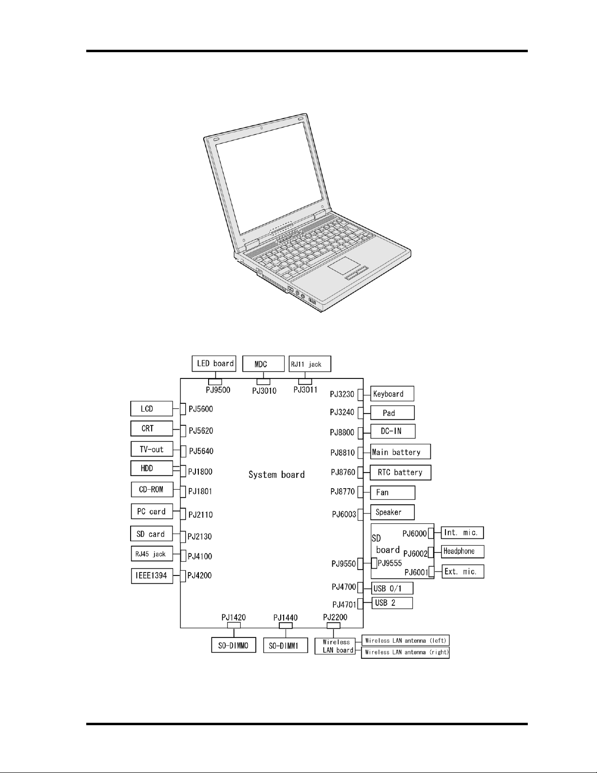
Figure 1-1 shows the front of the computer and Figure 1-2 shows the system units
configuration.
Figure 1-1 Front of the computer
Figure 1-2 System unit configuration
PORTEGE A200 Maintenance Manual (960-499) 1-5
Page 20
1 Hardware Overview 1.1 Features
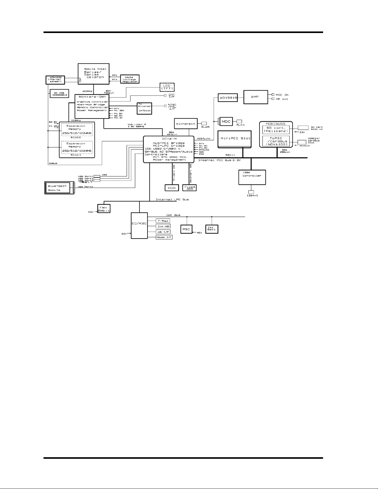
Figure 1-3 shows the system block diagram.
Figure 1-3 System block diagram
1-6 PORTEGE A200 Maintenance Manual (960-499)
Page 21

1.1 Features 1 Hardware Overview
The PC contains the following components.
? CPU
Intel Mobile® Pentium®-M Processor
A 1.60GHz Intel Mobile® Pentium® M Processor with a 1.60GHz internal clock,
400MHz bus and 1.308V to 0.748V core operation.
Cache memory: 64KB primary cache and 2MB secondary cache.
Intel Mobile® Celeron®-M Processor
A 1.4GHz Intel Mobile® Celeron®-M Processor with a 1.4GHz internal clock,
400MHz bus.
Cache memory: 64KB primary cache and 512KB secondary cache.
? Memory
Two memory slots (DDR266). Memory modules of 256MB, 512MB or
1GB(1,024MB) can be installed to a maximum of 2GB (2,048MB).
? 3.3V operation
? Access time 6ns
? Memory Supporting PC-2700
? BIOS ROM (FWH)
? 8Mbit (512K?16-bit chip)
? PCI chipset
This gate array incorporates the following elements and functions.
? North Bridge: Intel 855GME (GMCH-M)
? Banias Processor System bus support
? DRAM control ( supports DDR200/DDR256)
? Built-in graphic control
? RGB, DVI, DVO interface
? AGP master slave interface (Complies with AGP V2.0)
? PCI interface (Complies with PCI Rev 2.2)
? Complies with ACPI 1.0
? Supports Intel Speed step Technology
? 732-ball (37.5x37.5mm) micro FCBGA package
PORTEGE A200 Maintenance Manual (960-499) 1-7
Page 22

1 Hardware Overview 1.1 Features
? South Bridge: Intel 82801DBM (ICH4 -M)
? PCI 3.3V/5V tolerance interface
? Steerable PCI interrupts for PCI device P lug-and-Play
? Enhanced DMA controller
? Interrupt controller
? Counter/timers
? Distributed DMA supported
? PC/PCI DMA supported
? Serial IRQ supported
? Low Pin Count (LPC) host controller
? Plug -and-Play supported
? ACPI supporting features
? Built-in PCI IDE controller
? USB interface
? SMBus interface
? Audio system
? SW modem interface
? 421-ball (31mm x 31mm) BGA package
? PC card controller (YEBISUSS)
? PCI interface (PCI Revision2.2)
? Chipset interface
? CardBus/PC Card controller (Yenta Version2.2) :2 slots
? SD memory card controller (SDHC Ver.1.2)
? SDIO card controller (Ver.1.1)
? Smart card interface
? SIO(UART) controller(MS Debug Port Specification ver.1.0)
? Docking station interface
? External device interface
? 1.0mm pitch pin/17mm PBGA package
? VGA controller
Included in the North Bridge.
? Modem controller
Supported by Agere-made Modem controller and Askey-made MDC using the
secondary AC97 Line.
? LAN controller (Intel–made ED82562ET (Kinnereth))
Controls LAN and supports 100Base-TX and 10Base-T.
1-8 PORTEGE A200 Maintenance Manual (960-499)
Page 23

1.1 Features 1 Hardware Overview
? Other main system chips
? EC/KBC (Mitsubishi-made M306K9FCLRP)
? PSC (Toshiba made TMP87PM48V01U)
? Clock Generator (ICS-made ICS950812GT)
? TV Encoder (Chrontel-made CH7011A)
? SOUND CODEC (ADI-made AD1981B)
? AMP (Matsushita-Made AN12940AA-VF)
PORTEGE A200 Maintenance Manual (960-499) 1-9
Page 24
1 Hardware Overview 1.2 Hard Disk Drive
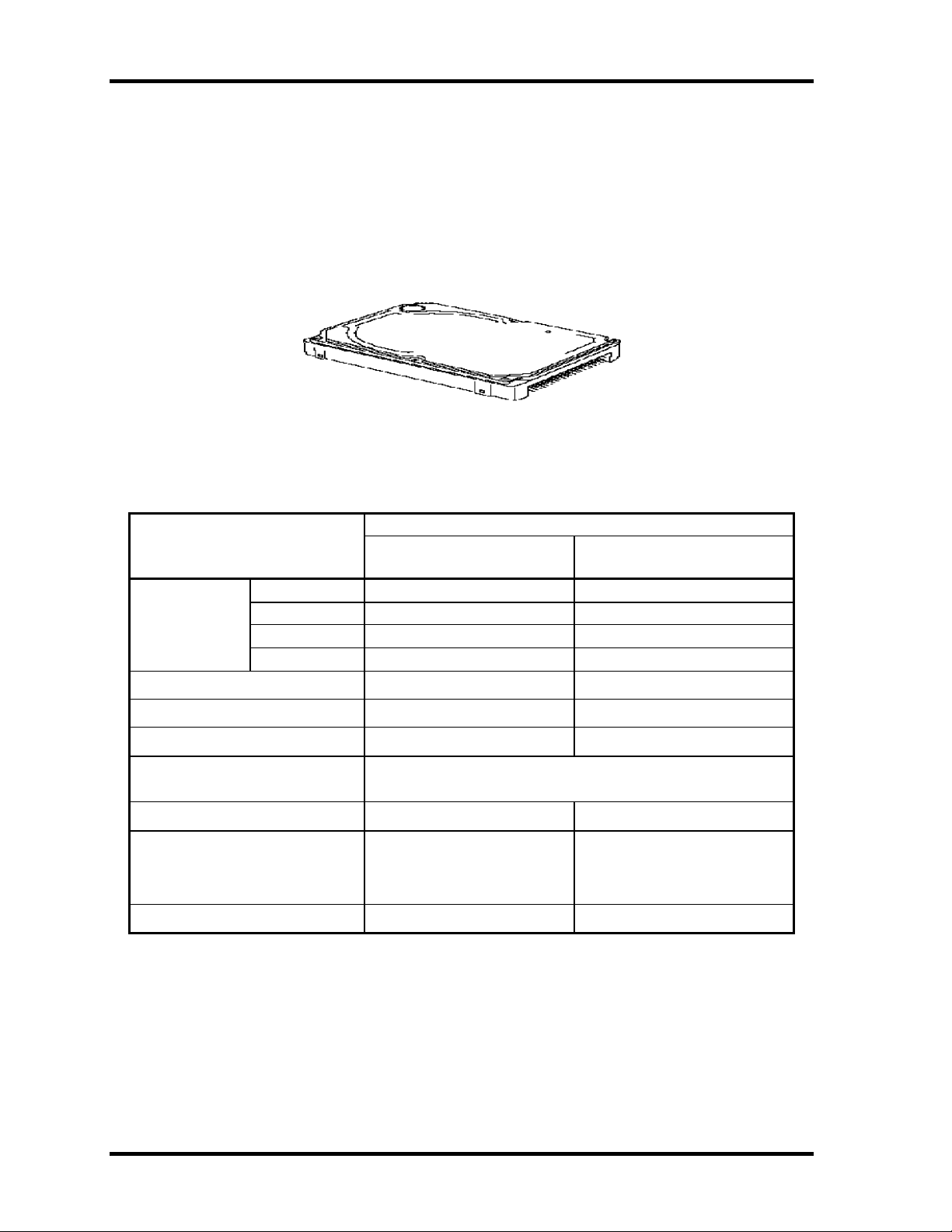
1.2 Hard Disk Drive
The HDD is a random-access, non-volatile storage device. It has a non-removable 2.5-inch
magnetic disk and mini-Winchester type magnetic heads. The computer is equipped with a
40 or 60GB HDD.
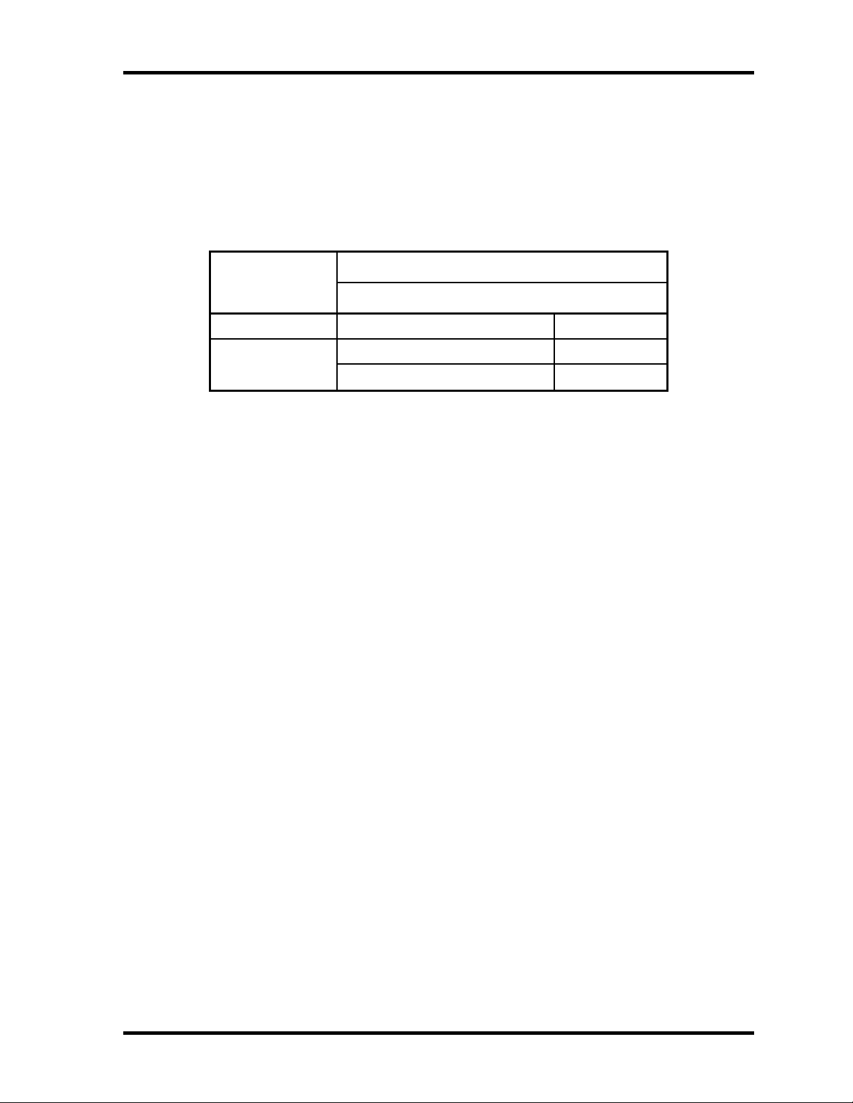
Figure 1-4 shows a view of the 2.5-inch HDD and Tables 1-1 lists the specifications.
Figure 1-4 2.5-inch HDD
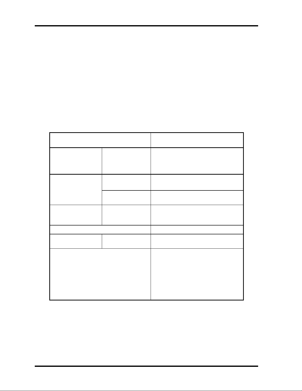
Table 1-1 2.5-inch HDD specifications
specifications
Parameter
Outline Width (mm) 69.85 69.85
dimensions Height (mm) 9.5 9.5
Depth (mm) 100.0 100.0
Weight (g) 95 95
Storage size (formatted) 40 60
Speed (RPM) 4200 4,200
Data transfer speed (Mb/s) 175.0-341.7 175.0-341.7
Interface transfer rate (MB/s) 100 max.
Track density (Ktpi) 88.1 88.1
Average seek time (ms)
Read
Write
Start time (ms) 4 4
TOSHIBA
HDD2190B
12
-
TOSHIBA
HDD2189B
(Ultra DMA mode)
12
-
1-10 PORTEGE A200 Maintenance Manual (960-499)
Page 25
1.3 Keyboard 1 Hardware Overview
1.3 Keyboard
The 84-key (US) or 85-key (UK) keyboard that consists of character keys and control keys is
mounted The keyboard is connected to membrane connector on the system board and
controlled by the keyboard controller on the system board.
Figure1-5 is a view of the keyboard.
See Appendix E about a layout of the keyboard.
Figure 1-5 Keyboard
PORTEGE A200 Maintenance Manual (960-499) 1-11
Page 26
1 Hardware Overview 1.4 Optical Drive
1.4 Optical Drive
1.4.1 CD-RW/DVD-ROM Drive
This drive is a combination of DVD-ROM and CD-R/RW Drive. It is full-size and runs
either 12cm (4.72-inch) or 8cm (3.15-inch) DVD/CDs without an adaptor. This drive reads
CD-ROM at maximum 24-speed, reads DVD-ROM at maximum 8-speed and writes CD-R at
maximum 24-speed, and writes CD-RW at 4-speed.
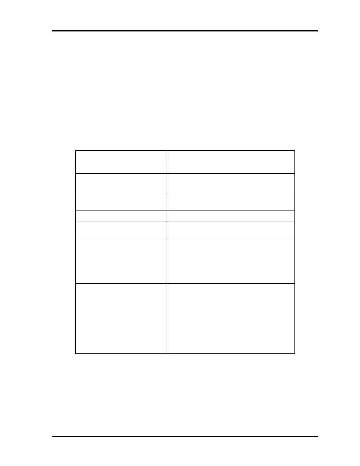
The specifications are listed in Table 1-2.
Table 1-2 CD-RW/DVD-ROM drive specifications
Parameter
Outline Width (mm) 128
Dimensions Height (mm) 9.5
Depth (mm) 126
Date transfer speed
READ
Write CD-R
ATAPI interface PIO mode
Buffer memory 2MB
Access time DVD-ROM
CD supported CD: CD -DA, CD-ROM, CD-ROM XA
DVD-ROM
CD-ROM
CD-RW
DMA mode
Ultra DMA mode
CD-ROM
4X, 8x(CLV), Max. 24X(ZCLV)
16.6 MB/s(Multiword Mode2)
CD-R, CD -RW
Photo CD, Video CD
CD-Extra(CD+), CD text
DVD: DVD-ROM DVD-R
DVD-RW(Ver. 1.1)
DVD-RAM(2.6GB/4.7GB)
DVD+R, DVD+RW
Matsushita
G8CC0001N710
Max. 8X CAV
Max. 24x CAV
4X (CLV)
16.6MB/s (PIO Mode4)
33.3MB (Mode2)
170ms typ. (1/3 stroke)
150ms typ. (1/3 stroke)
1-12 PORTEGE A200 Maintenance Manual (960-499)
Page 27
1.4 Optical Drive 1 Hardware Overview
1.4.2 DVD-multi Drive
This drive is a combination of CD-R/RW, DVD-R/RW and DVD-RAM Drive. It is full-size
and runs either 12cm (4.72-inch) or 8cm (3.15-inch) DVD/CDs without an adapter. This
drive reads CD-ROM at maximum 24-speed, reads DVD-ROM at maximum 8-speed, writes
CD-R at maximum 16-speed, writes CD-RW at maximum 4-speed, writes DVD-R at
maximum 2-speed, writes DVD-RW at maximum 2-speed and writes DVD-RAM at
maximum 2-speed.
Specifications for the DVD multi drive are described in table 1-3.
Table 1-3 DVD-Multi drive specifications
Item
ATAPI Burst (MB/sec) 33.3 (Ultra DMA MODE2)
16.6 (PIO MODE4, Multi word MODE2)
Average access time (ms) CD-ROM 150 (typ.)
Data buffer (MB) 2
Speed (Read)r CD-ROM 24x max. (CAV)
DVD-ROM 8x max (CAV)
Speed (Write) CD-R 16x max. (ZCLV)
Supported Format CD: CD-DA, CD-ROM, CD -R, CD-RW
CD-ROMXA
Photo CD, Video CD
CD-Extra(CD+), CD-text
DVD :DVD-VIDO, DVD-ROM
DVD-R (3.9GB, 4.7GB)
DVD-RW (Ver.1.1)
DVD-RAM (2.6GB, 4.7GB, 9.4GB)
DVD+R, DVD+RW
Matsushita
G8CC0001P710
DVD-ROM 180 (typ.)
CD-RW 4x (CLV)
HSRW 4x, 8x (CLV)
DVD-R 1x, 2x (CLV)
DVD-RW 1x, 2x (CLV)
DVD-RAM 2x (ZCLV)
PORTEGE A200 Maintenance Manual (960-499) 1-13
Page 28
1 Hardware Overview 1.5 TFT Color Display
1.5 TFT Color Display
The TFT color display consists of a LCD module and FL inverter board.
1.5.1 LCD Module
The LCD module used for the TFT color display uses a backlight as the light source and can
display images and characters of 262,144 colors with 1024?768 resolution. The video
controller is incorporated into the North Bridge chip and can control both internal and
external XGA-support displays simultaneously.
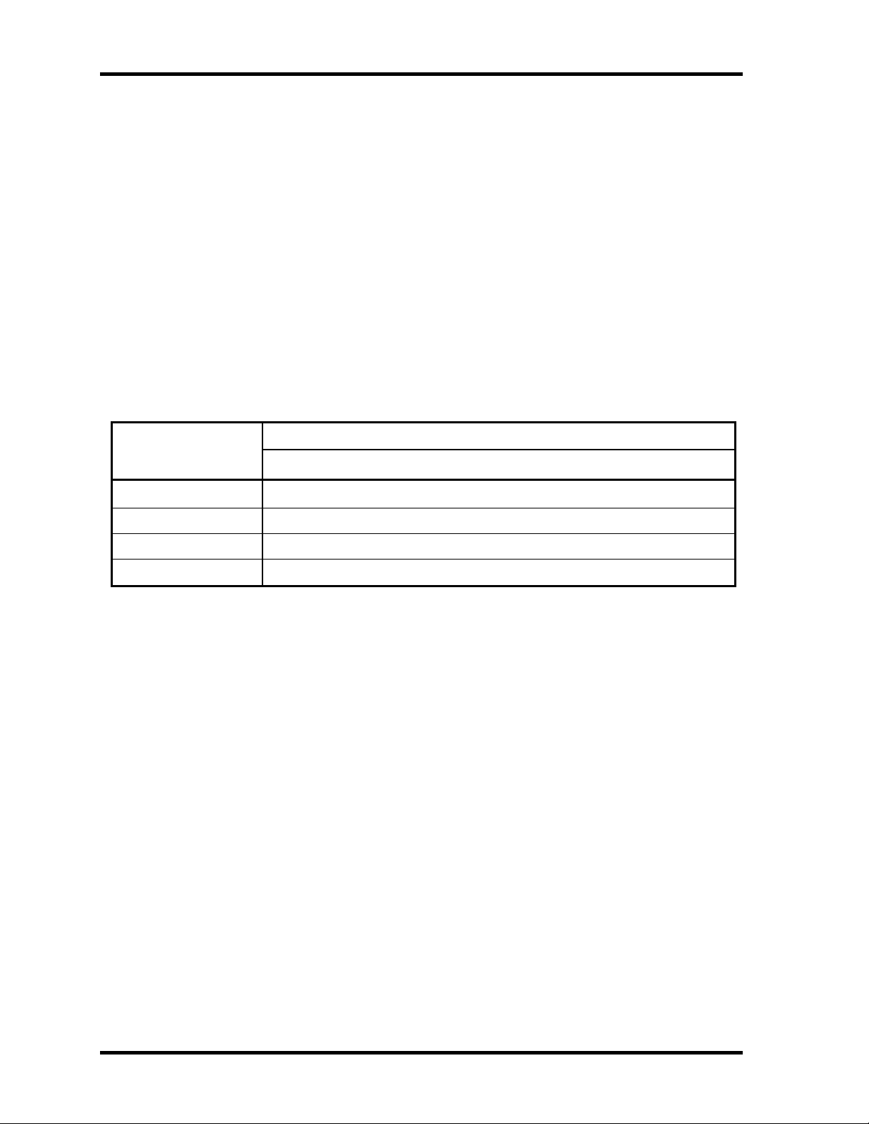
Table 1-4 shows the specifications.
Table 1-4 LCD module specifications (TMD-made 12.1 TFT)
Item
Number of Dots
Dot spacing (mm) 0.240(H) x 0.240(V)
Display range (mm) 245.76(H) x 184.32(V)
Outline dimensions 261.0(w) x 199.0(H) x 5.0Max(D)
Specifications
G33C0000J210
1024(W)?768(H)
1-14 PORTEGE A200 Maintenance Manual (960-499)
Page 29
1.5 TFT Color Display 1 Hardware Overview
1.5.2 FL Inverter Board
The FL inverter board supplies a high frequency current to illuminate the LCD module FL.
Table 1-5 lists the FL inverter board specifications.
Table 1-5 FL inverter board specifications
Item
Input Voltage (V) DC 5
Voltage (Vrms) 750(MAX) Output
Current (mArms) 6.0(MAX)
Specifications
G71C00011121
PORTEGE A200 Maintenance Manual (960-499) 1-15
Page 30
1 Hardware Overview 1.6 Power Supply
1.6 Power Supply
The power supply supplies 19 different voltages to the system board.
The power supply micro controller has the following functions.
1. Judges that the DC power supply ( AC adapter) is connected to the computer.
2. Detects DC output and circuit malfunctions.
3. Controls the battery icon, and DC IN icon.
4. Turns the battery charging system on and off and detects a fully charged battery.
5. Turns the power supply on and off.
6. Provides more accurate detection of a low battery.
7. Calculates the remaining battery capacity.
8. Controls the transmission of the status signal of the main battery.
Table 1-6 lists the power supply output specifications.
Table 1-6 Power supply output specifications(1/2)
Name Voltage [V] Use
PPV 1.308-0.748 CPU,GMCH, ICH4 -M
PTV 1.05 CPU, GMCH, ICH4-M
1R35-P1V 1.35 GMCH
1R25-P1V 1.25 DDR-SDRAM termination
MR1R25-
B1V
1R5-P1V 1.5 TV, GMCH, IVH4 -M
1R5-S1V 1.5 ICH4-M
2R5-B2V 2.5 GMCH, DDR-SDRAM
P3V 3.3
E3V 3.3 YEBISUSS, PC Card Power, mini-PCI, MDC
BT-P3V 3.3 Bluetooth
1.25
GMCH, DDR-SDRAM
Clock Generator, Thermal Sensor, GMCH, SDRAM(SPD), TV,
IEEE1394, ICH4-M, AD1981B, mini-PCI, EC/KBC, LCD,
SD card Power, KINNERTH
S3V 3.3 ICH4-M, EC/KBC, Flash Memory, PSC
P5V 5
1-16 PORTEGE A200 Maintenance Manual (960-499)
CRT, ICH4 -M, FL inverter, LEDs, HDD, ODD, KB, PAD,
Bluetooth Power
Page 31

1.6 Power Supply 1 Hardware Overview
Table 1-6 Power supply output specifications(2/2)
Name Voltage [V] Use
SND-P5V 5 AN12940AA(Amp)
A4R7-P4V 4.7 AD1981B, Line IN, Amp, Head Phone, Ring Phone
E5V 5 PC Card Power, USB Power
M5V 5 ICH4-M, MAX6501, LEDs
MCV 5 PSC
R3V 2.0-3.5 ICH4-M(RTC)
PORTEGE A200 Maintenance Manual (960-499) 1-17
Page 32

1 Hardware Overview 1.7 Batteries
1.7 Batteries
The PC has the following two batteries.
? Main battery
? Real time clock (RTC) battery
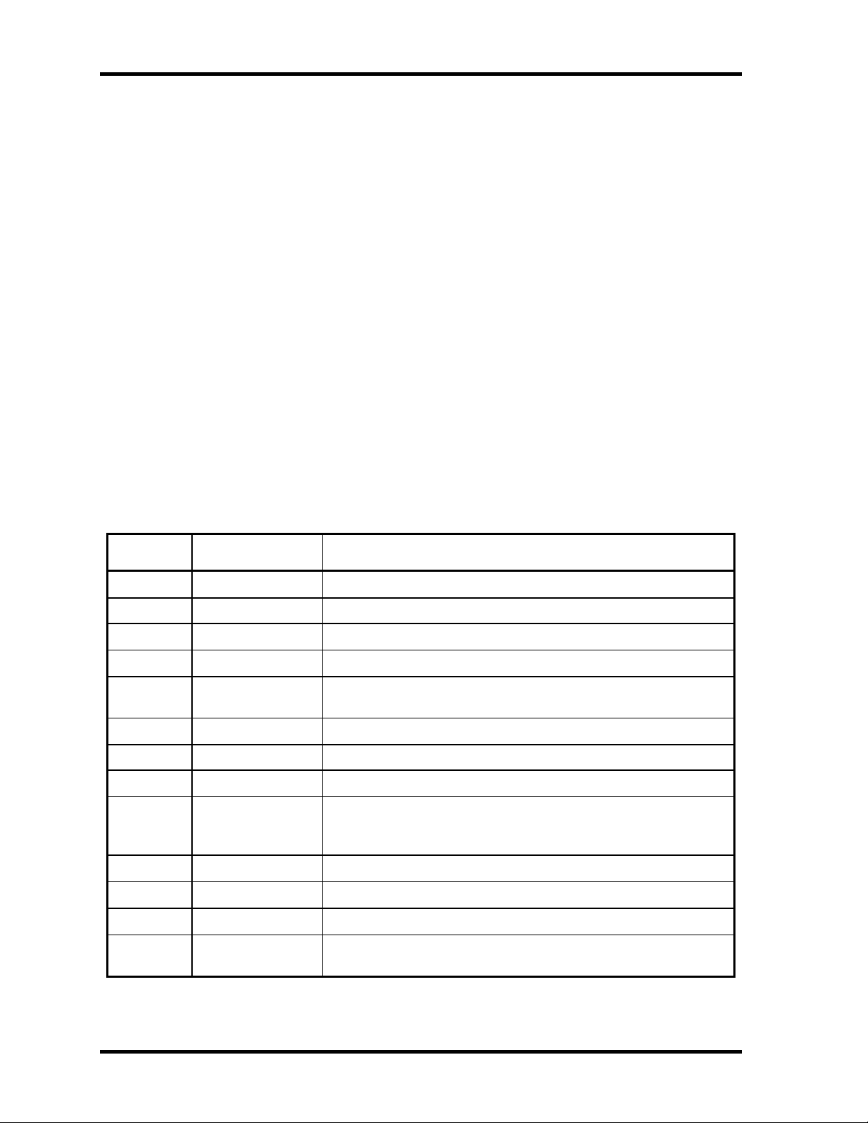
Table 1-7 lists the specifications for these two batteries.
Table 1-7 Battery specifications
Battery Name Battery Element Output Voltage Capacity
Main battery G71C0003Y110 Lithium ion 10.8 V 4,400 mAh
Real time clock
(RTC) battery
P71035009115 Lithium ion 2.4 V 16 mAh
1.7.1 Main Battery
The main battery is the primary power supply for the computer when the AC adapter is not
connected. In resume (instant recovery) mode, the main battery maintains the current status
of the computer.
The approximate operating time on fully charged battery is as follows:
Table 1-8 Operating time
Model Operating time
Pentium model About 4.6 hours
Celeron model About 4.3 hours
The approximate maintaining time of fully charged battery after power off is as follows:
Table 1-9 Maintaining time
Boot mode Standby mode
About 25days About 6 days
1-18 PORTEGE A200 Maintenance Manual (960-499)
Page 33

1.7 Batteries 1 Hardware Overview
1.7.2 Main Battery Charging Control
Battery charging is controlled by a power supply microprocessor. The power supply
microprocessor controls power supply and detects a full charge when the AC adapter and
battery are connected to the computer. The system charges the battery using quick charge or
trickle charge.
? Quick Battery Charge
When the AC adapter is connected, normal charges is used while the system is turned
on, and quick charge is used while the system is turned off or in suspend mode. Table
1-10 shows the approximate time required for charging battery.
Table 1-10 Time required for charging battery
Main battery Charging Time
Normal charge About 4 to 10 hours
Quick battery charge is stopped in the following cases.
1. The main battery is fully charged.
2. The main battery is removed.
3. Main battery or AC adapter voltage is abnormal.
4. Charging current is abnormal.
? Trickle charge
When the main battery is fully charged and the AC adapter is plugged in, the power
supply microcontroller automatically switches from quick charge to trickle charge.
Quick charge About 2.5 hours
PORTEGE A200 Maintenance Manual (960-499) 1-19
Page 34

1 Hardware Overview 1.7 Batteries
1.7.3 RTC Battery
The RTC battery provides the power supply to maintain the date, time, and other system
information in memory.
Table 1-11 lists the battery charging time.
Table 1-11 RTC battery charging time
Item Time
Charging
time
AC adapter or main battery in use
(Power ON)
about 14 hours
Table 1-12 lists the approximate maintaining time of fully charged battery after power off.
Table 1-12 Maintaining time
Mainta ining Time
RTC battery About 30 days
1-20 PORTEGE A200 Maintenance Manual (960-499)
Page 35

1.8 AC Adapter 1 Hardware Overview
1.8 AC Adapter
The AC adapter is also used to charge the battery.
Table 1-13 lists the AC adapter specifications.
Table 1-13 AC adapter specifications
Parameter
Input voltage AC 90 to 264V
Input frequency 50Hz/60Hz
Input current/
power
Output voltage DC 15V
Output current 4.0A
Specification
G71C0002S310
1.5A or less
(100Vac, 240Vac/4A load)
PORTEGE A200 Maintenance Manual (960-499) 1-21
Page 36

Chapter 2 Troubleshooting Procedures
Page 37

2 Troubleshooting Procedures
2
2-ii PORTEGE A200 Maintenance Manual (960-499)
Page 38

2 Troubleshooting Procedures
Chapter 2 Contents
2.1 Troubleshooting .........................................................................................................2-1
2.2 Troubleshooting Flowchart........................................................................................2-2
2.3 Power Supply Troubleshooting..................................................................................2-6
Procedure 1 Power Supply Icon Check......................................................2-7
Procedure 2 Error Code Check...................................................................2-9
Procedure 3 Connection Check................................................................2-14
Procedure 4 Quick Charge Check ............................................................2-14
Procedure 5 Replacement Check..............................................................2-15
2.4 System Board Troubleshooting................................................................................2-16
Procedure 1 Message Check ....................................................................2-17
Procedure 2 Debug Port Check ................................................................2-19
Procedure 3 Diagnostic Test Program Execution Check .........................2-27
Procedure 4 Replacement Check..............................................................2-27
2.5 USB FDD Troubleshooting .....................................................................................2-28
Procedure 1 FDD Head Cleaning Check ..................................................2-28
Procedure 2 Diagnostic Test Program Execution Check .........................2-29
Procedure 3 Connector Check and Replacement Check..........................2-30
2.6 HDD Troubleshooting .............................................................................................2-31
Procedure 1 Message Check ....................................................................2-31
Procedure 2 Partition Check.....................................................................2-32
Procedure 3 Format Check.......................................................................2-33
Procedure 4 Diagnostic Test Program Execution Check .........................2-34
Procedure 5 Connector Check and Replacement Check..........................2-35
2.7 Optical Drive Troubleshooting ................................................................................2-36
Procedure 1 Diagnostic Test Program Execution Check .........................2-36
Procedure 2 Connector Check and Replacement Check..........................2-36
PORTEGE A200 Maintenance Manual (960-499) 2-iii
Page 39

2 Troubleshooting Procedures
2.8 Display Troubleshooting ..........................................................................................2-37
Procedure 1 External Monitor Check.......................................................2-37
Procedure 2 Diagnostic Test Program Execution Check .........................2-37
Procedure 3 Connector Check and Cable Check .....................................2-37
Procedure 4 Replacement Check..............................................................2-38
2.9 Keyboard Troubleshooting ......................................................................................2-39
Procedure 1 Diagnostic Test Program Execution Check .........................2-39
Procedure 2 Connector Check and Replacement Check..........................2-39
2.10 Touch Pad Troubleshooting.....................................................................................2-40
Procedure 1 Diagnostic Test Program Execution Check .........................2-40
Procedure 2 Connector Check and Replacement C heck..........................2-40
2.11 SD Card Slot Troubleshooting .................................................................................2-41
Procedure 1 Check on Windows XP ........................................................2-41
Procedure 2 Connector Check and Replacement Check..........................2-41
2.12 Modem Troubleshooting..........................................................................................2-42
Procedure 1 Diagnostic Test Program Execution Check .........................2-42
Procedure 2 Connector Check and Replacement C heck..........................2-42
2.13 LAN Troubleshooting..............................................................................................2-43
Procedure 1 Diagnostic Test Program Execution Check .........................2-43
Procedure 2 Connector Check and Replacement C heck..........................2-43
2.14 Sound Troubleshooting............................................................................................2-44
Procedure 1 Diagnostic Test Program Execution Check .........................2-44
Procedure 2 Connector Check..................................................................2-45
Procedure 3 Replacement Check..............................................................2-46
2.15 Wireless LAN Troubleshooting...............................................................................2-47
Procedure 1 Transmitting-Receiving Check ............................................2-47
Procedure 2 Antenna Connection Check .................................................2-48
Procedure 3 Replacement Check..............................................................2-48
2-iv PORTEGE A200 Maintenance Manual (960-499)
Page 40

2 Troubleshooting Procedures
Figures
Figure 2-1 Troubleshooting flowchart.............................................................................2-3
Figure 2-2 A set of tool for debug port test ...................................................................2-19
Tables
Table 2-1 Battery icon....................................................................................................2-7
Table 2-2 DC IN icon.....................................................................................................2-7
Table 2-3 Error code.......................................................................................................2-9
Table 2-4 Result code...................................................................................................2-15
Table 2-5 Debugging port status ..................................................................................2-20
Table 2-6 FDD error code and status ...........................................................................2-29
Table 2-7 2.5” HDD error code and status...................................................................2-34
PORTEGE A200 Maintenance Manual (960-499) 2-v
Page 41

2 Troubleshooting Procedures
2-vi PORTEGE A200 Maintenance Manual (960-499)
Page 42

2.1 Troubleshooting 2 Troubleshooting Procedures
2
2.1 Troubleshooting
Chapter 2 describes how to determine which Field Replaceable Unit (FRU) in the computer is
causing the computer to malfunction. (The “FRU” means the replaceable unit in the field.)
The FRUs covered are:
1. Power supply 8. Touch pad
2. System Board 9. SD card slot
3. USB FDD 10. Modem
4. HDD 11. LAN
5. Optical Drive 12. Sound
6. Display 13. Wireless LAN
7. Keyboard
The Detailed replacement procedures are given in Chapter 4. Test Program operations are
described in Chapter 3.
The following tools are necessary for implementing the Diagnostics procedures:
For tools required for executing the Test Program, refer to the Chapter3. For tools required for
disassembling/assembling, refer to the Chapter 4.
1. A set of tools for debugging port test (test cable, test board, RS -232C cross cable,
display, D port FD)
2. A PC with a serial port (for displaying debug port test result)
3. Toshiba MS-DOS system FD
4. An external CRT display(for Display trouble shooting)
5. A SD card(for SD card slot trouble shooting)
6. An external microphone(for Sound trouble shooting)
7. Headphone(for Sound trouble shooting)
PORTEGE A200 Maintenance Manual (960-499) 2-1
Page 43

2 Troubleshooting Procedures 2.2 Troubleshooting Flowchart
2.2 Troubleshooting Flowchart
Use the flowchart in Figure 2-1 as a guide for determining which FRU malfunctions. Before
going through the flowchart steps, check the following:
? Ask the user if a password is registered and, if it is, ask him or her to enter the
password.
? Make sure that Toshiba Windows® XP is installed on the hard disk. Non-Toshiba
operating systems can cause the computer malfunction.
? Make sure all optional equipment is removed from the computer.
? Make sure the USB FDD and optical drive are empty.
2-2 PORTEGE A200 Maintenance Manual (960-499)
Page 44

2.2 Troubleshooting Flowchart 2 Troubleshooting Procedures
Figure 2-1 Troubleshooting flowchart (1/2)
PORTEGE A200 Maintenance Manual (960-499) 2-3
Page 45

2 Troubleshooting Procedures 2.2 Troubleshooting Flowchart
Figure 2-1 Troubleshooting flowchart (2/2)
2-4 PORTEGE A200 Maintenance Manual (960-499)
Page 46

2.2 Troubleshooting Flowchart 2 Troubleshooting Procedures
If the diagnostics program cannot detect an error, the problem may be intermittent. The Test
program should be executed several times to isolate the problem. Check the Log Utilities
function to confirm which diagnostic test detected an error (s), then perform the appropriate
troubleshooting procedures as follows:
1. If an error is detected on the System test, Memory test, Expansion test or Real timer
test, perform the System Board Troubleshooting Procedures in Section 2.4.
2. If an error is detected on the Floppy Disk test, perform the USB FDD Troubleshooting
Procedures in Section 2.5.
3. If an error is detected on the Hard disk test, perform the HDD Troubleshooting
Procedures in Section 2.6.
4. If an error is detected on the Optical drive test, perform the Optical Drive
Troubleshooting Procedures in Section 2.7.
5. If an error is detected on the Display test, perform the Display Troubleshooting
Procedures in Section 2.8.
6. If an error is detected on the Keyboard test, perform the Keyboard Troubleshooting
Procedures in Section 2.9.
7. If an error is detected on the Touch pad test, perform the Touch Pad Troubleshooting
Procedures in Section 2.10.
8. If an error is detected on the SD Card Slot test, perform the SD Card Slot
Troubleshooting Procedures in Section 2.11.
9. If an error is detected on the Modem test, perform the Modem Troubleshooting
Procedures in Section 2.12.
10. If an error is detected on the LAN test, perform the LAN Troubleshooting Procedures
in Section 2.13.
11. If an error is detected on the Sound test, perform the Sound Troubleshooting
Procedures in Section 2.14.
12. If an error is detected on the Wireless LAN test, perform the Wireless LAN
Troubleshooting Procedures in Section 2.15.
PORTEGE A200 Maintenance Manual (960-499) 2-5
Page 47

2 Troubleshooting Procedures 2.3 Power Supply Troubleshooting
2.3 Power Supply Troubleshooting
The power supply controller controls many functions and components. To determine if the
power supply is functioning properly, start with Procedure 1 and continue with the other
Procedures as instructed. The procedures described in this section are:
Procedure 1: Power Supply Icon Check
Procedure 2: Error Code Check
Procedure 3: Connection Check
Procedure 4: Quick Charge Check
Procedure 5: Replacement Check
2-6 PORTEGE A200 Maintenance Manual (960-499)
Page 48

2.3 Power Supply Troubleshooting 2 Troubleshooting Procedures
Procedure 1 Power Supply Icon Check
The following two icons indicate the power supply status:
? Battery icon
? DC IN icon
The power supply controller uses the power supply status with the Battery icon and the DC IN
icon as listed in the tables below.
Table 2-1 Battery icon
Battery icon Power supply status
Lights orange Battery is charged and the external DC is input. It has no relation with
ON/OFF of the system power.
Lights green Battery is fully charged and the external DC is input. It has no relation
with ON/OFF of the system power.
Blinks orange
(even intervals)
Flashes orange The bat tery level is low (*2) and the power switch is pressed on in the
Doesn’t light Any condition other than those above.
The battery level is low (*1) while the system power is ON.
battery driving.
*1: goes to hibernation
*2: in hibernation
Table 2-2 DC IN icon
DC IN icon Power supply status
Lights green DC power is being supplied from the AC adapter.
Blinks orange Power supply malfunction (*3)
Doesn’t light Any condition other than those above.
*3: When the power supply controller detects a malfunction, the DC IN icon blinks
orange. It shows an error code.
PORTEGE A200 Maintenance Manual (960-499) 2-7
Page 49

2 Troubleshooting Procedures 2.3 Power Supply Troubleshooting
When icons are blinking, perform the following procedure.
1. Remove the battery pack and the AC adapter and cut off the power supply to the
computer by force.
2. Re-attach the battery pack and the AC adapter.
If icons are still blinking after the operation above, check the followings:
Check 1 If the DC IN icon blinks orange, go to Procedure 2.
Check 2 If the DC IN icon does not light, go to Procedure 3.
Check 3 If the battery icon does not light orange or green, go to Procedure 4.
Caution: Use a recommended AC adapter (G71C0002S310).
2-8 PORTEGE A200 Maintenance Manual (960-499)
Page 50

2.3 Power Supply Troubleshooting 2 Troubleshooting Procedures
Procedure 2 Error Code Check
If the power supply microprocessor detects a malfunction, the DC IN icon blinks orange. The
blink pattern indicates an error as shown below.
? Start Off for 2 seconds
? Error code (8 bit)
“1” On for one second
“0” On for half second
Interval between data bits Off for half second
The error code begins with LSB (Least Significant bit).
Example: Error code 11h (Error codes are given in hexadecimal format.)
Check 1 Convert the DC IN icon blink pattern into the hexadecimal error code and
compare it to the tables below. Then go to Check 2.
Table 2-3 Error code
Error code Location
1*h DC power supply (AC adapter)
2*h Main battery
4*h S3V output
5*h 1R5-C1V output
6*h 1R8-C1V output
7*h PPV output
8*h PTV output
9*h E5V output
A*h E3V output
B*h PPV output
C*h 1R35-P1V output
D*h 1R25-P1V output
E*h 2R5-B2V output
PORTEGE A200 Maintenance Manual (960-499) 2-9
Page 51

2 Troubleshooting Procedures 2.3 Power Supply Troubleshooting
? DC power supply (AC adapter)
Error code Meaning
10h AC Adapter output voltage is over 16.5V.
11h Commondock output voltage is over 16.5V.
12h Current from the DC power supply is over 6.05A.
13h Current from the DC power supply is over 0.5A when there is no load.
14h Abnormal current has been sensed 0[A].
? Main battery
Error code Meaning
21h Main battery charge current is over 6.05A.
22h Main battery discharge current is over 0. 5A when there is no load.
23h Main battery charge current is over 3.1A when AC adapter is not
connected.
? S3V output
Error code Meaning
? 1R5-C1V output
Error code Meaning
24h Abnormal current has been sensed 0[A].
25h Main battery charge current is over 0.3A.
40h S3V voltage is 3.14V or less when the computer is powered on/off.
45h S3V voltage is 3.14V or less at power-on. (CV support)
50h 1R5-C1V voltage is over 1.8V when the computer is powered on/off.
51h 1R5-C1V voltage is 1.275V or less when the computer is powered on.
52h 1R5-C1V voltage is 1.275V or less at power-on.
53h 1R5-C1V voltage is 1.275V or less while the computer is suspended.
54h 1R5-C1V voltage is abnormal during shutdown. (CV support)
55h 1R5-C1V voltage is 1.275V or less when the computer is booting up.
(CV support)
2-10 PORTEGE A200 Maintenance Manual (960-499)
Page 52

2.3 Power Supply Troubleshooting 2 Troubleshooting Procedures
? 1R8-C1V output
Error code Meaning
60h 1R8-C1V voltage is over 2.16V when the computer is powered on/off.
61h 1R8-C1V voltage is 1.53V or less when the computer is powered on.
62h 1R8-C1V voltage is 1.53V or less when the computer is booting up.
63h 1R8-C1V voltage is 1.53V or less while the comput er is suspended.
64h 1R8-C1V voltage is abnormal during shutdown.
65h 1R8-C1V voltage is 1.53V or less at power -on.
? PPV output
Error code Meaning
70h PPV voltage is over 1.80V when the computer is powered on/off.
71h PPV voltage is 0.56V or less when the computer is powered on.
? PTV output
? E5V output
72h PPV voltage is 0.56V or less at power -on.
73h PPV voltage is 0.56V or more when the computer is powered off.
Error code Meaning
80h PTV voltage is over 1.26V when the computer is powered on/off.
81h PTV voltage is 0.89V or less when the computer is powered on.
82h PTV voltage is 0.89V or less at power -on.
83h PTV voltage is 0.89V or more when the computer is powered off.
84h PTV voltage is 0.89V or less when the computer is suspended.
Error code Meaning
90h E5V voltage is over 6.00V when the computer is powered on/off.
91h E5V voltage is 4.50V or less when the computer is powered on.
92h E5V voltage is 4.50V or less at power-on.
93h E5V voltage is 4.50V or more wh en the computer is powered off.
94h E5V voltage is 4.50V or less while the computer is suspended.
PORTEGE A200 Maintenance Manual (960-499) 2-11
Page 53

2 Troubleshooting Procedures 2.3 Power Supply Troubleshooting
? E3V output
Error code Meaning
A0h E3V voltage is over 3.96V when the computer is powered on/off.
A1h E3V voltage is 2.81V or less when the computer is powered on.
A2h E3V voltage is 2.81V or less at power-on.
A3h E3V voltage is over 2.81V or more when the computer is powered off.
A4h E3V voltage is 2.81V or less while the computer is suspended.
? PPV output
Error code Meaning
B0h PPV voltage is over 1.80V when the computer is powered on/off.
B1h PPV voltage is 0.56V or less when the computer is powered on.
B2h PPV voltage is 0.56V or less at power -on.
? 1R35-P1V output
Error code Meaning
B3h PPV voltage is 0.56V or more when the computer is powered off.
C0h 1R35-P1V voltage is over 1.62V when the computer is powered on/off.
C1h 1R35-P1V voltage is 1.147V or less when the computer is powered on.
C2h 1R35-P1V voltage is 1.147V or less at power-on.
C3h 1R35-P1V voltage is 1.147V or more when the computer is powered
off.
C4h 1R35-P1V voltage is 1.147V or less while the computer is suspended.
2-12 PORTEGE A200 Maintenance Manual (960-499)
Page 54

2.3 Power Supply Troubleshooting 2 Troubleshooting Procedures
? 1R25-P1V output
Error code Meaning
D0h 1R25-P1V voltage is over 1.50V when the computer is powered on/off.
D1h 1R25-P1V voltage is 1.063V or less when the computer is powered on.
D2h 1R25-P1V voltage is 1.063V or less at power-on.
D3h 1R25-P1V voltage is 1.063V or more when the computer is powered
off.
D4h 1R25-P1V voltage is 1.063V or less while the computer is suspended.
? 2R5-B2V output
Error code Meaning
E0h 2R5-B2V voltage is over 3.00V when the computer is powered on/off.
E1h 2R5-B2V voltage is 2.125V or less when the computer is powered on.
E2h 2R5-B2V voltage is 2.125V or less at power-on.
E3h 2R5-B2V voltage is 2.125V or more when the computer is powered off.
E4h 2R5-B2V voltage is 2.125V or less while the computer is suspended.
Check 2 In the case of error code 10h or 12h:
? Make sure the AC adapter and AC power cord are firmly plugged into the DC
IN 15 V socket and wall outlet. If the cables are connected correctly, go to the
following step:
? Connect a new AC adapter and AC power cord. If the error still exists, go to
Procedure 5.
Check 3 In the case of error code 2 Xh:
? Go to Procedure 3.
Check 4 For any other errors, go to Procedure 5.
PORTEGE A200 Maintenance Manual (960-499) 2-13
Page 55

2 Troubleshooting Procedures 2.3 Power Supply Troubleshooting
Procedure 3 Connection Check
The wiring diagram related to the power supply is shown below:
Any of the connectors may be disconnected. Perform starting from Check 1.
Check 1 Plug the AC power cord from the wall outlet and check it with a tester.
If the cord is cut, replace with a new one. If the cord is not cut, go to Check 2.
Check 2 Make sure the AC adapter and the AC power cord are firmly plugged into the DC -
IN 15 V jack and wall outlet. If these cables are connected correctly, go to Check 3.
Check 3 Check if the DC -IN jack is loosed. If so, go to Procedure 5. If not, go to Check 4.
Check 4 Make sure the battery pack is installed in the computer correctly. If the battery is
properly installed and the battery icon still does not light, go to Procedure 4.
Procedure 4 Quick Charge Check
The power supply may not charge the battery pack. Perform the following procedures:
1. Reinstall the battery pack.
2. Attach the AC adaptor and turn on the power. If you cannot turn on the power, go to
Procedure 5.
3. Run the Diagnostic test, go to System test and execute subtest 06 (Quick charge)
described in Chapter 3.
2-14 PORTEGE A200 Maintenance Manual (960-499)
Page 56

2.3 Power Supply Troubleshooting 2 Troubleshooting Procedures
4. When charge is complete, the diagnostics test displays the result code. Check the result
code against the table below and perform any ne cessary check.
Table 2-4 Result code
Result code Contents Check items
0 The battery is charging normally. Normal
1 The battery is fully charged. Normal
2 The AC adaptor is not connected. Check 1
3 The AC adaptor output voltage is not normal. Check 1
4 The battery is not installed. Check 2
5 The battery’s output voltage is not normal. Check 3
6 The battery’s temperature is not normal. Check 4
7 A bad battery is installed. Check 2
8 Any other problems. Check 5
Check 1 Make sure the AC adaptor and AC power cord are firmly plugged into the DC IN
jack and the wall outlet. If these cables are connected correctly, replace the AC
adaptor (and/or AC power cord, if necessary). Go to Check2.
Check 2 Make sure the battery is properly installed. If the battery is properly installed, go to
Check 3.
Check 3 The battery pack may be completely discharged. Wait a few minutes to charge the
battery pack. If the battery pack is still not charged, go to Check 4.
Check 4 The battery’s temperature is too hot or cold. Return the temperature to a normal
operating condition. If the battery pack still is not charged, go to Check 5.
Check 5 Replace the battery pack with a new one. If the battery pack still is not charged, go
to Procedure 5.
Procedure 5 Replacement Check
The system board may be disconnected or damaged. Replace the system board with a new one
following the steps described in Chapter 4, Replacement Procedures.
PORTEGE A200 Maintenance Manual (960-499) 2-15
Page 57

2 Troubleshooting Procedures 2.4 System Board Troubleshooting
2.4 System Board Troubleshooting
This section describes how to determine if the system board is defective. Start with Procedure
1 and continue with the other procedures as instructed. The procedures described in this
section are:
Procedure 1: Message Check
Procedure 2: Debug port Check
Procedure 3: Diagnostic Test Program Execution Check
Procedure 4: Replacement Check
2-16 PORTEGE A200 Maintenance Manual (960-499)
Page 58

2.4 System Board Troubleshooting 2 Troubleshooting Procedures
Procedure 1 Message Check
When the power is turned on, the system performs the Initial Reliability Test (IRT) installed
in the BIOS ROM. The IRT tests each IC on the system board and initializes it.
? If an error message is shown on the display, perform Check 1.
? If there is no error message, go to Procedure 2.
? If MS-DOS or Windows XP is properly loaded, go to Procedure 4.
Check 1 If one of the following error messages is displayed on the screen, press the F1 key
as the message instructs. These errors occur when the system configuration
preserved in the RTC memory (CMOS type memory) is not the same as the actual
configuration or when the data is lost.
If you press the F1 key as the message instructs, the SETUP screen appears to set
the system configuration. If any other error message is displayed, perform Check 2.
(a)*** Bad HDD type ***
Check system. Then press [F1] key ......
(b)*** Bad configuration ***
Check system. Then press [F1] key ......
(c)*** Bad memory size ***
Check system. Then press [F1] key ......
(d)*** Bad time function ***
Check system. Then press [F1] key ......
(e)*** Bad check sum (CMOS) ***
Check system. Then press [F1] key ......
(f)*** Bad check sum (ROM) ***
Check system. Then press [F1] key ......
(g)RTC battery is low or CMOS checksum is inconsistent
Press [F1] key to set Date/Time
Check 2 If the following error message is displayed on the screen press any key as the
message instructs.
The following error message appears when data stored in RAM under the resume
function is lost because the battery has become discharged or the system board is
damaged. Go to Procedure 3.
WARNING: RESUME FAILURE.
PRESS ANY KEY TO CONTINUE.
If any other error message is displayed, perform Check 3.
PORTEGE A200 Maintenance Manual (960-499) 2-17
Page 59

2 Troubleshooting Procedures 2.4 System Board Troubleshooting
Check 3 The IRT checks the system board. When the IRT detects an error, the system stops
or an error message appears.
If one of the following error messages (1) through (17), (22) or (23) is displayed,
go to Procedure 4.
If error message (18) is displayed, go to the Keyboard Troubleshooting Procedures
in Section 2.9.
If error message (19), (20) or (21) is displayed, go to the 2.5” HDD
Troubleshooting Procedures in Section 2.6.
(1) PIT ERROR
(2) MEMORY REFRESH ERROR
(3) TIMER CH.2 OUT ERROR
(4) CMOS CHECKSUM ERROR
(5) CMOS BAD BATTERY ERROR
(6) FIRST 64KB MEMORY ERROR
(7) FIRST 64KB MEMORY PARITY ERROR
(8) VRAM ERROR
(9) SYSTEM MEMORY ERROR
(10) SYSTEM MEMORY PARITY ERROR
(11) EXTENDED MEMORY ERROR
(12) EXTENDED MEMORY PARITY ERROR
(13) DMA PAGE REGISTER ERROR
(14) DMAC #1 ERROR
(15) DMAC #2 ERROR
(16) PIC #1 ERROR
(17) PIC #2 ERROR
(18) KBC ERROR
(19) HDC ERROR
(20) HDD #0 ERROR
(21) HDD #1 ERROR
(22) TIMER INTERRUPT ERROR
(23) RTC UPDATE ERROR
2-18 PORTEGE A200 Maintenance Manual (960-499)
Page 60

2.4 System Board Troubleshooting 2 Troubleshooting Procedures
Procedure 2 Debug Port Check
Check the D port status by a debug port test. The tool for debug port test is shown below.
Figure 2-2 A set of tool for debug port test
The test procedures are follows:
1. Connect the debug test cable to the connector PJ2000 of the system board. For
disassembling to connect the test cable, refer to Chapter 4.
2. Connect the debug port test cable and RS -232C cross-cable to the test board.
3. Connect the RS -232C cross-cable to the PC that displays the test results.
4. Boot the computer in MS-DOS mode.
5. Execute GETDPORT.COM in the text menu in CPU REAL mode. (Insert the FD for
starting D port into FDD and input “FD starting drive:>dport”.)
6. When the D port status is FFFFh (normal status), go to Procedure 3.
7. When the D port status falls into any status in Table 2-5, go to Procedure 4.
PORTEGE A200 Maintenance Manual (960-499) 2-19
Page 61

2 Troubleshooting Procedures 2.4 System Board Troubleshooting
Table 2-5 Debugging port status (1/7)
D port
Status
F000h
F001h
F002h
Contents
Clears software rest bit.
Permits A20 line.
Initializes special register and Intel chipset.
Initializes PIT CH0 only (for HOLD_ON).
Initializes flag of factor rewriting of BIOS.
Checks CHECK SUM.
Transition to protect mode.
Calculates the checksum of Boot block? HLT at checksum error
Calculates the checksum of block other than Boot block.
Checks rewriting EC/KBC? Goes to BIOS rewriting process at request for
rewriting.
Executes KBC initializing sequence.
Transmits KBC enable command.
Checks F12 key.
Checks for request of BIOS rewriting? Checksum error of blocks other than
Boot Block, at the request of F12 rewriting request.
F003h Transfers the process to the System BIOS IRT side.
BIOS rewriting process
Initializes peculiar HW to the model.
Initializes GPIO I/O space.
Permits BIOS writing.
Controls serial interrupts.
Releases the write-protect of BIOS.
Permits the SMBus I/O space.
Permits the access to SMBus.
Configuration of DRAM
Permits cache (only L1 Cache).
Memory clear
2-20 PORTEGE A200 Maintenance Manual (960-499)
Page 62

2.4 System Board Troubleshooting 2 Troubleshooting Procedures
Table 2-5 Debugging port status (2/7)
D port
status
F004h Changes ROM BIOS to RAM BIOS.
F005h Stores scan codes.
Sets TASK_1ms_TSC.
F0006h Inputs key.
Reads CHGBIOSA.EXE/CHGFIRMA.EXE.
FDC RESET
Sets parameters for 2HD(1.44MB) and the transmission rate.
Reads the first sector. If 1.44MB 2HD, decides.
Sets the parameter for 2DD(720KB) and the transmission rate.
Searches CHGBIOSA.EXE from the root directory.
Calculates the head and sector for start directory.
Reads one sector from the root directory.
Searches the entry of “CHGBIOSA.EXE”/”CHGFIRMA.EXE” from the
sector.
Reads the EXE header of “CHGBIOSA.EXE”/ “HGFIRMA.EXE”.
Goes to input key, when any error generates.
Contents
Executes “CHGBIOSA.EXE”/ “CHGFIRMA.EXE”.
(F003h) Prohibits cache.
Initializes special registers.
F100h
F101h Checks the type and size of DRAM (in Cold Boot ).
F102h Cache configuration
Initializes PIT channel 1 (sets the refresh interval to 30µ s.).
Checks the DRAM size.
When the DRAM size = 0, it halts.
Tests the stack area of SM-RAM? When it can not be used for stack, it
halts.
Permits cache. (L1 Cache only)
Access test of CMOS (in COLD boot only). ? When any error, it halts.
Checks the battery level of CMOS.
Checks the checksum of CMOS.
Initializes CMOS data (1).
Sets IRT status. (setting boot status and IRT busy flag, remaining bit =0)
Stores the DRAM size.
PORTEGE A200 Maintenance Manual (960-499) 2-21
Page 63

2 Troubleshooting Procedures 2.4 System Board Troubleshooting
Table 2-5 Debugging port status (3/7)
D port
status
F103h Resume branch (in COLD boot only)
No resume at CMOS error
No resume, if resume status code is not set.
Checks for resume error.
ICH4-M Power Failure error? Resume error 7Ah
Checks checksum of SM-RAM.? Resume error 73H
Checks change of memory configuration. ? Resume error 73H
Checks checksum of RAM area of system BIOS. ? Resume error 79H
Goes to resume process (RESUME_MAIN).
Resume error process
Forbids all SMIs.
Clears resume status.
Returns to ROM.
Forwards the area of C0000h~ EFFFFh to PCI. (Forbids DRAM)
Sets resume error factors.
Contents
Copies ROM/RAM of system BIOS. ? halts at error.
F104h Initializes SM RAM.
Checks WakeUp factor.
Rewrites on SM RAM base and stores CPU state map.
Permits only SMI by ASMI.
2-22 PORTEGE A200 Maintenance Manual (960-499)
Page 64

2.4 System Board Troubleshooting 2 Troubleshooting Procedures
Table 2-5 Debugging port status (4/7)
D port
status
F105h Initializes devices that are necessary to be initialized before initializing PCI bus.
Tests and initializes PIT.(only in COLD boot)
Sets test patterns to PIT#0 channel 0.
Checks if the test patterns can be read.
Initializes PIT channel 0 (sets the interval of timer interrupts to 55ms.
Initializes PIT channel 2. (sets the frequency of sound generator to
664Hz.)
Tests PIT channel 1. (Check if the refresh signal operates correctly in the
condition that the refresh frequency is 30µ s.)
Tests PIT channel 2. (Check if the speaker gate operates correctly.)
Measures CPU clock.
Permits SMI other than auto off function.
Check if the Input power is over the rated one.
Controls battery-charging current.
Check if the AC adapter current is over the rated one.
Executes dividing process for measuring IRT time.
Contents
Sets the clock generator.
Checks the parameter block A.
Initializes CPU.
Measures the frequency of CPU and difference of frequency of Gsv High and
Low.
Checks if the CPU supports Geyserville.
Sets the CPU clock to High.
F106h Stores the memory size of each ROW to the buffer.
Reads EC version.
Renews the flash ROM type.
Judges the destination (Japan or overseas) from the DMI data.
Checks CMOS default setting. (Bad Battery , Bad checksum (ROM, CMOS)) ?
sets to default.
Initializes ACPI table. (for execution of option ROM)
PORTEGE A200 Maintenance Manual (960-499) 2-23
Page 65

2 Troubleshooting Procedures 2.4 System Board Troubleshooting
Table 2-5 Debugging port status (5/7)
D port
status
F106h Initializes devices which are necessary to be initialized before initializing
PCI bus.
AC’97 control
Initializes temperature control information.
Initializes HC and recognizes devices.
Turns off the display controls “Reset”.
Initializes KBC.
Initializes sounds.
Obtains the multi box status of PC.
Starts HC initializing sequence and recognizes devices.
Controls permission/prohibition of LAN.
Initializes PIC.
Tests PIC.
Initializes password.
F107h Initializes PCI bus.
Checks WakeUp factor.
Content
F108h Raises the task waiting for the completion of INIT_PCI.
Initializes CMOS date (2).
Initializes PnP.
Sets setting up item.
Sets power off enable.
Clears wakeup conditions.
Controls CPU speed.
Control panel opening/closing
Initializes PC card slot.
F109 Raises task waiting for the completion of PnP resource.
Initializes H/W-related to PnP.
Auto-configuration of PCI
Generates work for auto-configuration.
Configuration
Restores the result of VGA configuration.
2-24 PORTEGE A200 Maintenance Manual (960-499)
Page 66

2.4 System Board Troubleshooting 2 Troubleshooting Procedures
Table 2-5 Debugging port status (6/7)
D port
status
F10Ah Raises the task waiting for the completion of PCI_configuration.
Initializes H/W necessary after PCI configuration.
Enables power off.
Generates out put code.
F10Bh FIRST_64KB_CHECK (Memory checks of first 64KB)
F10Ch INIT_INT_VECTOR (Initialization of vector)
F10Dh INIT_NDP(Initialization of NDP)
F10Eh
F10Fh
F110h
F111h
INIT_SYSTEM (Initialization of system)
Stores CMOS error status into IRT_ERR_STS_BUF.
Starts initializing of TIMER.
Initializes buffer for power save.
Initializes EC and reads battery information.
Renews system BIOS. (Renews model name, EDID information for LCD. )
INIT_Display (Waiting for completion of initializing VGA chip and initializing
BIOS)
DISP_LOGO (Display of LOGO)
SYS_MEM_CHECK (Memory check of conventional memory)
Contents
F112h
F114h
F115h
F116h
F117h
F118h
F11Bh
F11Ch
EXT_MEM_CHECK (Exception check in protect mode)
Initializes conventional memory.
CHK_DMA_PAGE(Check of DMA Page Register)
CHECK_DMAC(Check of DMAC)
INIT_DMAC (Initialization of DMA)
BOOT_PASSWORD (Password check)
Waits for completion of initializing HDD
Checks key input during IRT. (waits here the completion of KBC
initialization.)
Initializes ATA priority.
Clears security buffer.
EX_IO_ROM_CHECK (Check of optional I/O ROM)
PRE_BOOT_SETUP
Stores the value of 40:00h.(for saving/restoring SIO)
Sets font address for resume password.
Sets the repeat parameter to USB KB.
Gets the key information pressed during IRT.
Stores T_SHADOW_RAM_SIZE.
PORTEGE A200 Maintenance Manual (960-499) 2-25
Page 67

2 Troubleshooting Procedures 2.4 System Board Troubleshooting
Table 2-5 Debugging port status (7/7)
D port
status
F11Ch
Contents
Renews system resources right before Boot.
Rewrites memory map of INT15h E820h function.
Renews tables for DMI.
Copies ACPI table to the top of expansion memory.
Waits for the completion of writing PSC version to BIOS.
Waits for the completion of setting clock generator. When any error, halts at
DEBUG
PORT=1EH.
Releases NMI Mask.
Checksums TIT.
Clears flag during IRT of Runtime side.
Renews checksum of Runtime side.
Initializes Bluetooth.
Checks upgrade of CPU, HDD and others.
Checks for the maintenance card.
Prohibits PC card not used.
Sets the WAKEUP status data for ACPI.
Initializes the HW right before BOOT and waits for the completion.
Sets battery save mode.
Sets date.
Waits for the completion of initializing AC-Link.
Renews DMI Wakeup factor and SM-BIOS structure table.
Closes configuration area for PCI device.
Cache control
Process related to CPU
Erases the information HW -reset from EC.
Renews parameter block A.
Makes the CPU clock set up by SETUP.
Waits for motor-off of HDD disable.
After process of PRE_BOOT_SETUP
Clears PWRBTN_STS.
Sets Power Button to “disable”.
Clears PME_EN of built-in LAN.
2-26 PORTEGE A200 Maintenance Manual (960-499)
Page 68

2.4 System Board Troubleshooting 2 Troubleshooting Procedures
Procedure 3 Diagnostic Test Program Execution Check
Execute the following tests form Diagnostic Program. These tests check the system board and
I/O unit. Refer to Chapter 3, Tests and Diagnostic, for more information on how to perform
these tests.
1. System test
2. Memory test
3. Keyboard test
4. Display test
5. Floppy Disk test
6. Hard Disk test
7. Real Timer test
8. NDP test
9. Expansion test
10. CD-ROM/DVD-ROM test
11. Wireless LAN test
12. Sound test
13. LAN/Modem/Bluetooth/IEEE1394 test
If an error is detected during these tests, go to Procedure 4.
Procedure 4 Replacement Check
The system board connectors may be disconnected. Disassemble the computer following the
steps described in Chapter 4, Replacement Procedures and perform Check 1.
Check 1 Visually check for the following:
a) Cracked or broken connector housing
b) Damaged connector pins
If connectors are in good condition, but there is still a problem, go to Check 2.
Check 2 The system board may be damaged. Replace the system board with a new one
following the steps described in Chapter 4, Replacement Procedures.
PORTEGE A200 Maintenance Manual (960-499) 2-27
Page 69

2 Troubleshooting Procedures 2.5 USB FDD Troubleshooting
2
2.5 USB FDD Troubleshooting
This section describes how to determine if the USB 3.5” FDD is functioning properly.
Perform the steps below starting with Procedure 1 and continuing with the other procedures as
required.
Procedure 1: FDD Head Cleaning Check
Procedure 2: Diagnostic Test Program Execution Check
Procedure 3: Connector Check and Replacement Check
Procedure 1 FDD Head Cleaning Check
FDD head cleaning is one option available in the Diagnostic Program.
Insert the Diagnostics Disk in the floppy disk drive of the computer, turn on the computer and
run the test. And then clean the FDD heads using the cleaning kit. If the FDD still does not
function properly after cleaning, go to Procedure 2.
Detailed operation is given in Chapter 3, Tests and Diagnostics.
If the test program cannot be executed on the computer, go to Procedure 3.
2-28 PORTEGE A200 Maintenance Manual (960-499)
Page 70

2.5 USB FDD Troubleshooting 2 Troubleshooting Procedures
Procedure 2 Diagnostic Test Program Execution Check
Insert the Diagnostics Disk in the FDD of the computer, turn on the computer and run the test.
Refer to Chapter 3, Tests and Diagnostics, for more information about the diagnostics test
procedures.
Make sure the floppy disk is formatted correctly and that the write protect tab is disabled.
Floppy disk drive test error codes and their status names are listed in Table 2-6. If any other
errors occur while executing the FDD diagnostics test, go to Check 1.
Table 2-6 FDD error code and status
Code Status
01h Bad command
02h Address mark not found
03h Write protected
04h Record not found
06h Media replaced
08h DMA overrun error
09h DMA boundary error
10h CRC error
20h FDC error
40h Seek error
60h FDD not drive
80h Time out error (Not ready)
EEh Write buffer error
Check 1 If the following message is displayed, disable the write protect tab on the floppy
disk by sliding the write protect tab to “write enable”. If any other message appears,
perform Check 2.
Write protected
Check 2 Make sure the floppy disk is formatted correctly. If it is, go to Procedure 3.
PORTEGE A200 Maintenance Manual (960-499) 2-29
Page 71

2 Troubleshooting Procedures 2.5 USB FDD Troubleshooting
Procedure 3 Connector Check and Replacement Check
The USB FDD connector may be disconnected from the system board. Check visually that the
connector is connected firmly.
Check 1 Make sure the USB FDD cable is firmly connected to the USB port 0,1 or 2.
If any of the connections are loose, reconnect firmly and repeat Procedure 2. If
there is still an error, go to Check 2.
Check 2 The USB FDD may be defective or damaged. Replace it with a new one. If the
FDD is still not functioning properly, perform Check 3.
Check 3 Replace the system board with a new one following the steps in Chapter 4,
Replacement Procedures.
2-30 PORTEGE A200 Maintenance Manual (960-499)
Page 72

2.6 HDD Troubleshooting 2 Troubleshooting Procedures
2.6 HDD Troubleshooting
This section describes how to determine if the 2.5” HDD is functioning properly. Perform the
steps below starting with Procedure 1 and continuing with the other procedures as required.
Procedure 1: Message Check
Procedure 2: Partition Check
Procedure 3: Format Check
Procedure 4: Diagnostic Test Program Execution Check
Procedure 5: Connector Check and Replacement Check
Caution: The contents of the 2.5” hard disk will be erased when the HDD
troubleshooting procedures are executed. Transfer the contents of the hard disk
to floppy disks or other storage drive(s). For the backup, refer to the User’s
Manual.
Procedure 1 Message Check
When the power is turned on, the system performs the Initial Reliability Test (IRT) installed
in the BIOS ROM. When the test detects an error, an error message is displayed on the screen.
Make sure of no floppy disk in the FDD. Turn on the computer and check the message on the
screen. When an OS starts from the 2.5” HDD, go to Procedure 3. Otherwise, start with Check
1 below and perform the other checks as instructed.
Check 1 If any of the following messages appear, go to Procedure 3. If the following
messages do not appear, perform Check 2.
HDC ERROR
or
HDD #X ERROR (After 5 seconds this message will disappear.)
Check 2 If either of the following messages appears, go to Check 3. If the following
messages do not appear, perform Check 5.
Insert system disk in drive
Press any key when ready .....
or
Non-System disk or disk error
Replace and press any key when ready
PORTEGE A200 Maintenance Manual (960-499) 2-31
Page 73

2 Troubleshooting Procedures 2.6 HDD Troubleshooting
Check 3 Check SETUP to see whether the Hard Disk option is set to Not used. If it is set to
Not used, choose another setting and return to Check 1. If it is not set to Not used,
go to procedure 2.
Procedure 2 Partition Check
Insert the Toshiba MS-DOS system disk and start the computer. Perform the following
checks:
Check 1 Type C: and press Enter. If you cannot change to drive C, go to Check 2. If you
can change to drive C, go to Procedure 2.
Check 2 Type FDISK and press Enter. Choose Display Partition Information from the
FDISK menu. If drive C is listed in the Display Partition Information, go to Check
3. If drive C is not listed, return to the FDISK menu and cho ose the option to
create a DOS partition or a logical DOS drive on drive C. If the problem still exists,
go to Procedure 2.
Check 3 If drive C is listed as active in the FDISK menu, go to Check 4. If drive C is not
listed as active, return to the FDISK menu and choose the option to set the active
partition for drive C. Then go to Procedure 2.
Check 4 Remove the system disk from the FDD and reboot the computer. If the problem
still exists, go to Procedure 2. Otherwise, the HDD is operating normally.
2-32 PORTEGE A200 Maintenance Manual (960-499)
Page 74

2.6 HDD Troubleshooting 2 Troubleshooting Procedures
Procedure 3 Format Check
The computer’s 2.5" HDD is formatted using the MS-DOS FORMAT program or the physical
format program of the test program. To format the 2.5" HDD, start with Check 1 below and
perform the other steps as required.
Refer to the MS-DOS Manual for the operation of MS-DOS. For the format by the test
program, refer to the Chapter 3.
Check 1 Format the 2.5" HDD using MS-DOS FORMAT command. Type as FORMAT
C:/S/U.
If the 2.5" HDD can not be formatted, perform Check 2.
Check 2 Using the MS-DOS FDISK command, set the 2.5" HDD partition. If the partition
is not set, go to Check 3. If it is set, format the 2.5" HDD using MS-DOS
FORMAT command.
Check 3 Using the Diagnostic Disk, format the 2.5" HDD with a format option (physical
format). If the 2.5" HDD is formatted, set the 2.5" HDD partition using MS-DOS
FDISK command.
If you cannot format the 2.5" HDD using the Tests and Diagnostic program, go to
Procedure 4.
PORTEGE A200 Maintenance Manual (960-499) 2-33
Page 75

2 Troubleshooting Procedures 2.6 HDD Troubleshooting
Procedure 4 Diagnostic Test Program Execution Check
The HDD test program is stored in the Dia gnostics Disk. Perform all of the HDD tests in the
Hard Disk Drive Test. Refer to Chapter 3, Tests and Diagnostics, for more information about
the HDD test program.
If an error is detected during the HDD test, an error code and status will be displayed. The
error codes and statuses are described in Table 2-7. If an error code is not displayed but the
problem still exists, go to Procedure 5.
Table 2-7 2.5” HDD error code and status
Code Status
01h Bad command
02h Address mark not found
04h Record not fou nd
05h HDC not reset
07h Drive not initialized
08h HDC overrun error (DRQ)
09h DMA boundary error
0Ah Bad sector error
0Bh Bad track error
10h ECC error
11h ECC recover enable
12h DMA CRC error
20h HDC error
40h Seek error
80h Time out error
AAh Drive not ready
BBh Undefined error
CCh Write fault
E0h Status error
EEh Access time out error
DAh No HDD
2-34 PORTEGE A200 Maintenance Manual (960-499)
Page 76

2.6 HDD Troubleshooting 2 Troubleshooting Procedures
Procedure 5 Connector Check and Replacement Check
The HDD is connected to the connector PJ1800 of the system board. The connecting portion
may be disconnected. Disassemble the computer following the steps described in Chapter 4,
Replacement Procedures and perform the following checks to check the connecting portion:
Check 1 Make sure the HDD is firmly connected to the system board.
If connection is loose, reconnect firmly and repeat Procedure 4. If there is still an
error, go to Check 2.
Check 2 The 2.5" HDD may be damaged. Replace it with a new one and check the
operation. If the problem still exists, perform Check 3.
Check 3 The system board may be damaged. Replace it with a new one following the
instructions in Chapter 4, Replacement Procedures.
PORTEGE A200 Maintenance Manual (960-499) 2-35
Page 77

2 Troubleshooting Procedures 2.7 Optical Drive Troubleshooting
2.7 Optical Drive Troubleshooting
To check if the optical drive is defective or malfunctioning, follow the troubleshooting
procedures below as instructed.
Procedure 1: Diagnostic Test Program Execution Check
Procedure 2: Connector Check and Replacement Check
Procedure 1 Diagnostic Test Program Execution Check
Execute the CD-ROM/DVD-ROM Test in the Diagnostic Program. Refer to Chapter 3, Tests
and Diagnostics for more information on how to perform the test program.
If any error is detected by the test, go to Procedure 2.
Procedure 2 Connector Check and Replacement Check
The optical drive is connected to the system board by the connector. The connector may be
disconnected from the system board or faulty. Disassemble the computer following the steps
described in Chapter 4 and perform the following checks:
Check 1 Make sure the following connector PJ1801 has been firmly connected to the
optical drive and the system board.
If the connection is loose, reconnect it firmly and return to Procedure 1. If there is
still an error, perform Check 2.
Check 2 The optical drive may be faulty. Replace the optical drive with a new one
following the steps in Chapter 4. If the optical drive is still not functioning
properly, perform Check 3.
Check 3 The system board may be faulty. Replace it with new one following t he
instructions in Chapter 4.
2-36 PORTEGE A200 Maintenance Manual (960-499)
Page 78

2.8 Display Troubleshooting 2 Troubleshooting Procedures
2.8 Display Troubleshooting
This section describes how to determine if the computer’s display is functioning properly.
Start with Procedure 1 and continue with the other procedures as instructed.
Procedure 1: External Monitor Check
Procedure 2: Diagnostic Test Program Execution Check
Procedure 3: Connector Check and Cable Check
Procedure 4: Replacement Check
Procedure 1 External Monitor Check
Connect an external monitor and tun on the computer. If there is no problem on it, the internal
LCD may be defective. Go to Procedure 3. If there is any problem on the external monitor, the
system board may be defective. Go to Procedure 2.
Procedure 2 Diagnostic Test Program Execution Check
The Display Test program is stored on the Diagnos tics disk. Insert the Diagnostics disk in the
computer’s floppy disk drive, turn on the computer and run the test. Refer to Chapter 3, Tests
and Diagnostics for details.
This program checks the display controller on the system board. If an error is detected, go to
Procedure 3.
Procedure 3 Connector Check and Cable Check
The LCD Module is connected to the system board by an LCD/FL cable. The FL inverter
board is also connected to the system board by an LCD/FL cable. The connectors may be
disconnected from the system board or may be damaged. Disassemble the computer following
the steps described in Chapter 4, Replacement Procedures.
PORTEGE A200 Maintenance Manual (960-499) 2-37
Page 79

2 Troubleshooting Procedures 2.8 Display Troubleshooting
If the connection is loose, reconnect firmly and restart the computer. If there is still an error,
go to Procedure 4.
Procedure 4 Replacement Check
Units related to display are a FL inverter board, Display module, System board and LCD/FL
cable. Any of the components may be damaged. Disassemble the computer following the steps
described in Chapter 4, Replacement Procedures, then perform the following checks:
(1) If the FL does not light, perform Check 1.
(2) If characters are displayed on the internal display but the display is not normal, perform
Check 3.
(3) If the FL lights even if the display cover is closed, perform Check 4.
Check 1 The LCD/FL cable may be damaged. Replace the cable with a new one. If there is
still an error, go to Check 2.
Check 2 The FL inverter board may be damaged. Replace it with a new one and repeat
Procedure 1. If there is still an error, go to Check 3.
Check 3 The LCD module may be damaged. Replace it with a new one and repeat
Procedure 1. If there is still an error, go to Check 4.
Check 4 The system board may be damaged. Replace the system board with a new one.
2-38 PORTEGE A200 Maintenance Manual (960-499)
Page 80

2.9 Keyboard Troubleshooting 2 Troubleshooting Procedures
2.9 Keyboard Troubleshooting
To determine if the computer’s keyboard is functioning properly, perform the following
procedures. Start with Procedure 1 and continue with the other procedures as instructed.
Procedure 1: Diagnostic Test Program Execution Che ck
Procedure 2: Connector Check and Replacement Check
Procedure 1 Diagnostic Test Program Execution Check
Execute the Keyboard Test in the Diagnostic Program. Refer to Chapter 3, Tests and
Diagnostics for more information on how to perform the test program.
If an error occurs, go to Procedure 2. If an error does not occur, the keyboard is functioning
properly.
Procedure 2 Connector Check and Replacement Check
The keyboard or system board may be disconnected or damaged. Disassemble the computer
following the steps described in Chapter 4, Replacement Procedures and perform the
following checks:
Check 1 Make sure the keyboard cable is firmly connected to the connector PJ3230 on the
system board.
If the connection is loose, reconnect firmly and repeat Procedure 1. If there is still
an error, go to Check 2.
Check 2 The keyboard may be damaged. Replace it with a new one following the
instructions in Chapter 4, Replacement Procedures. If the problem still exists,
perform Check 3.
Check 3 The system board may be damaged. Replace it with a new one following the
instructions in Chapter 4, Replacement Procedures.
PORTEGE A200 Maintenance Manual (960-499) 2-39
Page 81

2 Troubleshooting Procedures 2.10 Touch Pad Troubleshooting
2.10 Touch Pad Troubleshooting
To determine whether the Touch Pad is faulty or not, perform the following procedures:
Procedure 1: Diagnostic Test Program Execution Check
Procedure 2: Connector Check and Replacement Check
Procedure 1 Diagnostic Test Program Execution Check
Execute the touch pad test in the Diagnostic Program. Refer to Chapter 3, Tests and
Diagnostics for more information on how to perform the test program.
If any error is detected, perform Procedure 2. The pointing device is operating normally if no
error is detected.
Procedure 2 Connector Check and Replacement Check
The touch pad is connected to the system board with a flexible cable. This cable may have
come off the connector or the connector may have come off the system board. Disassemble
the computer and check the cable connections. See Chapter 4 for the disassembly procedure.
Check 1 Make sure the touch pad cable is securely connected to the connector PJ3240 on
the system board.
If the connection is loose, reconnect firmly and repeat Procedure 1. If there is still
an error, go to Check 2.
Check 2 The touch pad or PAD switch cable may be damaged. Replace it with a new one
following the instructions in Chapter 4, Replacement Procedures. If the problem
still exists, perform Check 3.
Check 3 The system board may be damaged. Replace it with a new one following the
instructions in Chapter 4, Replacement Procedures.
2-40 PORTEGE A200 Maintenance Manual (960-499)
Page 82

2.11 SD Card Slot Troubleshooting 2 Troubleshooting Procedures
2.11 SD Card Slot Troubleshooting
To check if the SD card slot is good or not, follow the troubleshooting procedures below as
instructed.
Procedure 1: Check on Windows XP
Procedure 2: Connector Check and Replacement Check
Procedure 1 Check on Windows XP
Insert the SD card into the slot. Check if the installed Windows recognizes automatically the
SD card and the data in the SD card can be read.
If the card is not recognized or data are not read, go to Procedure 2.
Procedure 2 Connector Check and Replacement Check
The SD card is connected to the connector PJ2130 of the system board.
Check 1 The SD card and the system board may be disconnected. Make sure the SD card is
firmly inserted to the PJ2130 of the system board. If the SD card is still not
functioning properly, perform Check 2.
Check 2 The SD card may be faulty. Replace it. If the problem continues, perform Check 3.
Check 3 The system board may be faulty. Replace it with a new one following the step in
Chapter 4.
PORTEGE A200 Maintenance Manual (960-499) 2-41
Page 83

2 Troubleshooting Procedures 2.12 Modem Troubleshooting
2.12 Modem Troubleshooting
To check if the modem is defective or malfunctioning, follow the troubleshooting procedures
below as instructed.
Procedure 1: Diagnostic Test Program Execution Check
Procedure 2: Connector Check and Replacement Check
Procedure 1 Diagnostic Test Program Execution Check
Execute the Modem test program available as part of the LAN/Modem/Bluetooth/IEEE1394
test program. This program checks the modem. Refer to Chapter 3, Tests and Diagnostics for
more information on how to perform the test program.
If any error is detected by the test, go to Procedure 2.
Procedure 2 Connector Check and Replacement Check
The Modem jack and MDC board is connected to the system board. If the modem
malfunctions, these connections may be bad or the MDC or system board might be faulty.
Disassemble the computer following the steps described in Chapter 4 and perform the
following checks:
Check 1 Make sure the MDC is firmly connec ted to the PJ3010 on System board and the
MDC cable is firmly connected to the PJ3011 on the system board.
If any connector is disconnected, connect it firmly and return to Procedure 1. If
there is still an error, perform Check 2.
Check 2 The MDC cable may be faulty. Replace it with a new one. If the modem is not still
working properly, perform Check 3.
Check 3 The MDC may be faulty. Replace it with a new one following the steps in Chapter
4. If the modem is not still working properly, perform Check 4.
2-42 PORTEGE A200 Maintenance Manual (960-499)
Page 84

2.12 Modem Troubleshooting 2 Troubleshooting Procedures
Check 4 The system board may be faulty. Replace it with a new one following the
instructions in Chapter 4.
PORTEGE A200 Maintenance Manual (960-499) 2-43
Page 85

2 Troubleshooting Procedures 2.13 LAN Troubleshooting
2.13 LAN Troubleshooting
To check if the computer’s LAN is defective or malfunctioning, follow the troubleshooting
procedures below as instructed.
Procedure 1: Diagnostic Test Program Execution Check
Procedure 2: Connector Check and Replacement Check
Procedure 1 Diagnostic Test Program Execution Check
Execute the LAN test program available as part of the LAN/Modem/Bluetooth/IEEE1394 test
program. Refer to Chapter 3, Tests and Diagnostics for more information on how to perform
the test program.
If any error is detected by the test, go to Procedure 2.
Procedure 2 Connector Check and Replacement Check
The LAN function is installed on the system board. The LAN jack is connected to the system
board. If the LAN malfunctions, the system board might be faulty.
Replace the system board with a new one following the steps described in Chapter 4.
2-44 PORTEGE A200 Maintenance Manual (960-499)
Page 86

2.14 Sound Troubleshooting 2 Troubleshooting Procedures
2.14 Sound Troubleshooting
To check if the sound function is defective or malfunctioning, follow the troubleshooting
procedures below as instructed.
Procedure 1: Diagnostic Test Program Execution Check
Procedure 2: Connector Check
Procedure 3: Replacement Check
Procedure 1 Diagnostic Test Program Execution Check
Execute the Sound test program. Refer to Chapter 3, Tests and Diagnostics for more
information on how to perform the test program.
If any error is detected by the test, go to Procedure 2.
PORTEGE A200 Maintenance Manual (960-499) 2-45
Page 87

2 Troubleshooting Procedures 2.14 Sound Troubleshooting
Procedure 2 Connector Check
The speaker, external microphone, internal microphone and headphone are connected to the
connectors on the system board and SD board shown in the following figure.
Any of the connections may be disconnected. Disassemble the computer following the steps
described in Chapter 4, Replacement Procedures and perform the following checks:
If the stereo speakers do not work correctly, perform Check 1.
If headphones do not work correctly, perform Check 2.
If sound recording by an external microphone does not work correctly, perform Check 3.
If sound recording by an internal microphone does not work correctly, perform Check 4.
Check 1 If the stereo speakers do not work properly, the speaker cables may be
disconnected. Make sure the speaker cables are firmly connected to PJ6003 on the
system board. If the stereo speakers are still not functioning properly, go to
Procedure 3.
Check 2 If headphones do not work properly, the SD board may be disconnected or the
headphone cable may be disconnected. Make sure the SD board is firmly
connected to PJ9550 on the system board and the headphone cable is connected to
the headphone jack PJ6002 on the SD board. If the sound function still does not
work properly, go to Procedure 3.
Check 3 If the sound recording function by an external microphone does not work properly,
the SD board may be disconnected or the external microphone cable may be
disconnected. Make sure the SD board is firmly connected to the connector PJ9550
on the system board and the external microphone cable is firmly connected to
microphone jack PJ6001 on the SD board. If recording is still not functioning
properly, go to Procedure 3.
Check 4 If the sound recording function by the internal microphone does not work properly,
the SD board may be disconnected or the internal microphone cable may be
disconnected. Make sure the SD board is firmly connected to the connector PJ9550
on the system board and the internal microphone cable is firmly connected to the
connector PJ6000 on the SD board. If recording is still not functioning properly, go
to Procedure 3.
2-46 PORTEGE A200 Maintenance Manual (960-499)
Page 88

2.14 Sound Troubleshooting 2 Troubleshooting Procedures
Procedure 3 Replacement Check
Check 1 If the stereo speakers do not sound properly, the stereo speakers may be defective
or damaged. Replace them with new ones. If the stereo speakers still do not work
properly, go to Check 5.
Check 2 If headphones do not sound properly, the SD board may be defective. Replace the
SD board with a new one. If the headphone still does not work properly, go to
Check 5.
Check 3 If the recording function by the external microphone does not work properly, the
SD board may be defective . Replace the SD board with a new one. If the recording
function still does not work properly, go to Check 5.
Check 4 If the recording function by the internal microphone does not work properly, the
SD board may be defective . Replace the SD board with a new one. If the recording
function still does not work properly, go to Check 5.
Check 5 The system board may be defective or damaged. Replace the system board with a
new one following the instructions in Chapter 4, Replacement Procedures.
PORTEGE A200 Maintenance Manual (960-499) 2-47
Page 89

2 Troubleshooting Procedures 2.15 Wireless LAN Troubleshooting
2.15 Wireless LAN Troubleshooting
To check if the Wireless LAN is good or not, follow the troubleshooting procedures below as
instructed.
Procedure 1: Transmitting-Receiving Check
Procedure 2: Antenna Connection Check
Procedure 3: Replacement Check
Procedure 1 Transmitting-Receiving Check
Make sure the wireless communication switch on the computer is turned ON. If it is not, turn
ON.
Refer to Chapter 3, Tests and Diagnostics for more information on how to perform the test
program.
Check 1 Execute test program for the wireless LAN function to check the transmitting-
receiving function of the wireless LAN. You will need a second computer t hat can
communicate by the wireless LAN .
If the computer passes the test, the function is correctly working.
If the computer does not pass the test, perform Procedure 2.
2-48 PORTEGE A200 Maintenance Manual (960-499)
Page 90

2.15 Wireless LAN Troubleshooting 2 Troubleshooting Procedures
Procedure 2 Antenna Connection Check
The wireless LAN function wiring diagram is shown below:
Any of the connections may be disconnected. Disassemble the computer following the steps
described in Chapter 4, perform the following checks:
Check 1 Make sure the wireless communication switch is “On”.
If the switch is “Off”, turn it “On”. If the wireless LAN is still not functioning
properly, perform Check 2.
Check 2 The wireless LAN board and the system board may be disconnected. Make sure
the wireless LAN board is firmly connected to the PJ2200 of the system board.
If the connector is disconnected, connect firmly and return to Procedure 1. If there
is still an error, go to Check 3.
Check 3 Make sure the wireless LAN antenna cables (black and white) are firmly connected
to the Wireless LAN board. If the antenna cables are disconnected, connect them
firmly then return to Procedure 1. If there is still an error, perform Procedure 3.
Procedure 3 Replacement Check
The wireless LAN board, wireless LAN antenna or the system board may be defective.
Disassemble the computer following the steps described in Chapter 4 and perform the
following checks.
Check 1 The wireless LAN board may be defective or damaged. Disassemble the computer
following the steps described in Chapter 4 and replace the board with a new one . If
there is still an error, go to Check 2.
Check 2 The wireless LAN antenna may be defective or damaged. Disassemble the
computer following the steps described in Chapter 4 and replace the board with a
new one. If there is still an error, go to Check 3.
Check 3 The system board may be defective or damaged. Disassemble the computer
following the steps described in Chapter 4 and replace the board with a new one .
PORTEGE A200 Maintenance Manual (960-499) 2-49
Page 91

Chapter 3 Tests and Diagnostics
Page 92

3 Tests and Diagnostics
3
3-ii PORTEGE A200 Maintenance Manual (960-499)
Page 93

3 Tests and Diagnostics
Chapter 3 Contents
3.1 The Diagnostic Test...................................................................................................3-1
3.1.1 Diagnostics menu .................................................................................3-1
3.1.2 H/W (Hardware) initial information setting tool..................................3-3
3.1.3 Heatrun test program............................................................................3-3
3.2 Executing the Diagnostic Test ...................................................................................3-4
3.2.1 Diagnostics menu (T&D).....................................................................3-4
3.2.2 H/W initial information setting tool.....................................................3-7
3.2.3 Heatrun test program............................................................................3-7
3.3 Setting of the hardware configuration........................................................................3-8
3.4 Heatrun Test.............................................................................................................3-11
3.5 Subtest Names..........................................................................................................3-12
3.6 System Test ..............................................................................................................3-14
3.7 Memory Test ............................................................................................................3-16
3.8 Keyboard Test ..........................................................................................................3-17
3.9 Display Test .............................................................................................................3-18
3.10 Floppy Disk Test......................................................................................................3-21
3.11 Printer Test...............................................................................................................3-23
3.12 Async Test ................................................................................................................3-25
3.13 Hard Disk Test.........................................................................................................3-26
3.14 Real Timer Test ........................................................................................................3-29
3.15 NDP Test..................................................................................................................3-31
3.16 Expansion Test.........................................................................................................3-32
3.17 CD-ROM/DVD-ROM Test .....................................................................................3-34
3.18 Error Code and Error Status Names.........................................................................3-35
3.19 Hard Disk Test Detail Status....................................................................................3-38
3.20 ONLY ONE TEST...................................................................................................3-40
3.20.1 Program Description...........................................................................3-40
3.20.2 Operations...........................................................................................3-40
PORTEGE A200 Maintenance Manual (960-499) 3-iii
Page 94

3 Tests and Diagnostics
3.21 Head Cleaning..........................................................................................................3-46
3.21.1 Function Description..........................................................................3-46
3.21.2 Operations...........................................................................................3-46
3.22 Log Utilities .............................................................................................................3-47
3.22.1 Function Description..........................................................................3-47
3.22.2 Operations...........................................................................................3-48
3.23 Running Test ............................................................................................................3-49
3.23.1 Function Description..........................................................................3-49
3.23.2 Operations...........................................................................................3-49
3.24 Floppy Disk Drive Utilities......................................................................................3-50
3.24.1 Function Description..........................................................................3-50
3.24.2 Operations...........................................................................................3-51
3.25 System Configuration..............................................................................................3-55
3.25.1 Function Description..........................................................................3-55
3.25.2 Operations...........................................................................................3-56
3.26 Wireless LAN Test Program (Intel-made b/g).........................................................3-57
3.27 Wireless LAN Test Program (Askey-made)............................................................3-61
3.28 LAN/Modem/Bluetooth/IEEE1394 Test Program ..................................................3-65
3.28.1 LAN test .............................................................................................3-65
3.28.2 Modem test .........................................................................................3-68
3.28.3 Bluetooth test......................................................................................3-69
3.28.4 IEEE1394 test.....................................................................................3-78
3.29 Sound Test program .................................................................................................3-79
3.29.1 Sound (Standard) test .........................................................................3-79
3.29.2 Sound (Legacy) test............................................................................3-81
3.29.3 CD Sound (Standard) test...................................................................3-82
3.30 SETUP .....................................................................................................................3-85
3.29.1 Function Description..........................................................................3-85
3.29.2 Accessing the SETUP Program..........................................................3-86
3-iv PORTEGE A200 Maintenance Manual (960-499)
Page 95

3 Tests and Diagnostics
Tables
Table 3-1 Subtest names ....................................................................................................3-12
Table 3-2 Error codes and error status names ....................................................................3-35
Table 3-3 Hard disk controller status register contents......................................................3-38
Table 3-4 Error register contents........................................................................................3-39
Table 3-5 Error message....................................................................................................3-71
Table 3-6 Error code for Bluetooth test (BD_ADDR) .......................................................3-72
Table 3-7 Error code for Bluetooth test (BD_ADDR of the DUT) ....................................3-76
Table 3-8 Lamp pattern of power button............................................................................3-95
PORTEGE A200 Maintenance Manual (960-499) 3-v
Page 96

3 Tests and Diagnostics
3-vi PORTEGE A200 Maintenance Manual (960-499)
Page 97

3.1 The Diagnostic Test 3 Tests and Diagnostics
3
3.1 The Diagnostic Test
This chapter explains how to use the Diagnostic Test programs to test the functions of the
computer’s hardware modules. The Diagnostics Programs are stored on some Diagnostic Disks.
There are Service Program Modules (DIAGNOSTIC MENU) and the Test Program Modules
(DIAGNOSTIC TEST MENU) on the Diagnostic Disk.
The Hardware Initial information Setting Tool consists of some programs which write the hardware
information or displays the current information of the computer. It is also included in one of
Diagnostic Disks.
The heatrun test is automatic test program which executes the some tests successively.
Note: Before starting the diagnostics, be sure to follow these steps:
1. Check all cables are connected firmly.
2. Exit any application and close Windows.
3. Check if [All Devices] is selected in the “Device Config.” in SETUP menu.
3.1.1 Diagnostics menu
The DIAGNOSTIC MENU consists of the following functions.
? DIAGNOSTIC TEST
? ONLY ONE TEST
? HEAD CLEANING
? LOG UTILITIES
? RUNNING TEST
? FDD UTILITIES
? SYSTEM CONFIGURATION
? EXIT TO MS-DOS
The DIAGNOSTIC TEST MENU contains the following functional tests:
? SYSTEM TEST
? MEMORY TEST
? KEYBOARD TEST
? DISPLAY TEST
? FLOPPY DISK TEST
? PRINTER TEST
? ASYNC TEST
PORTEGE A200 Maintenance Manual (960-499) 3-1
Page 98

3 Tests and Diagnostics 3.1 The Diagnostic Test
? HARD DISK TEST
? REAL TIMER TEST
? NDP TEST
? EXPANSION TEST
? CD-ROM/DVD-ROM TEST
Other tests are:
? Wireless LAN TEST (Wireless LAN TEST disk)
? LAN/Modem /Bluetooth/IEEE1394 TEST (LAN/Modem/Bluetooth/IEEE1394 TEST disk)
? Sound TEST (Sound TEST disk)
You will need the following equipment to perform some of the Diagnostic test programs.
? The Diagnostic Disks (T&D for maintenance for Main, LAN/Modem/Bluetooth/IEEE1394,
wireless LAN and Sound)
? A formatted working disk (Floppy disk test)
? USB FDD (for all tests)
? A USB test module (USB test )
? A USB cable (USB test)
? An external CRT monitor (Expansion test)
? A CD test media TOSHIBA CD-ROM TEST DISK or ABEX TEST CD-ROM (Sound
test)
? A DVD test media (DVD-ROM TEST DISK TSD-1) (Sound test)
? A music CD (Sound test)
? A store-bought CD-RW media (CD-ROM/DVD-ROM test)
? A microphone (Sound test)
? Headphones (Sound test)
? A cleaning kit to clean the floppy disk drive heads (Head Cleaning)
? An exclusive modem test jig (Nitto Electric Manufacture Co.,Ltd-made QE2000P01)
(Modem test)
? A module cable and RJ11 connector checker (Modem test)
? A LAN wraparound connector (LAN test)
? PC card wraparound connector (Expansion test)
? A display with monitor ID function (Expansion test)
? RS232C wraparound connector (Async test)
? A PC for wraparound test (Wireless LAN test/Bluetooth test/IEEE1394 test)
3-2 PORTEGE A200 Maintenance Manual (960-499)
Page 99

3.1 The Diagnostic Test 3 Tests and Diagnostics
3.1.2 H/W (Hardware) initial information setting tool
The H/W initial information setting tool consists of the following programs.
? Initial configuration
? Region write
? System configuration display
? E2PROM test (MAC/GUID/DMI)
You will need the following equipment to perform some of the programs.
? The Diagnostics Disk (Main T&D)
3.1.3 Heatrun test program
The heatrun test starts automatically after the selection.
You will need the following equipment to perform this program.
? The Diagnostics Disk (Main T&D)
PORTEGE A200 Maintenance Manual (960-499) 3-3
Page 100

3 Tests and Diagnostics 3.2 Executing the Diagnostic Test
3.2 Executing the Diagnostic Test
To start the DIAGNOSTIC PROGRAM, follow these steps:
1. Insert the Diagnostics disk in the floppy disk drive.
2. Insert the Diagnostics disk in the USB floppy disk drive and turn on the computer while
pressing U key. Then, press Enter and the following menu appears.
Microsoft Windows XX Startup Menu
---------------------------------------------------------
1. Repair Main (T&D)
2. Repair initial config set
3. Repair Heatrun (T&D)
Enter a choice: 1
To start the Diagnostics menu (T&D), press 1 and Enter.
To start the H/W initial information setting tool, press 2 and Enter.
To start the Heatrun test, press 3 and Enter.
Note: After replacing the system board or CPU, it is necessary to execute the subtest
01 Initial configuration in 3.3 Setting of the hardware configuration.
3.2.1 Diagnostics menu (T&D)
To execute this program, select 1- Repair Main (T&D) in the startup menu, press Enter.
The following menu appears.
TOSHIBA personal computer XXXXXX DIAGNOSTICS
version X.XX (c) copyright TOSHIBA Corp. 20XX
DIAGNOSTICS MENU :
1 - DIAGNOSTIC TEST
2 – ONLY ONE TEST
3 -
4 - HEAD CLEANING
5 - LOG UTILITIES
6 - RUNNING TEST
7 - FDD UTILITIES
8 - SYSTEM CONFIGURATION
9 - EXIT TO MS-DOS
3-4 PORTEGE A200 Maintenance Manual (960-499)
 Loading...