

Page 1
TOSHIBA
USER'S MANUAL
Model
7140CT/7200CT
R
Page 2

Copyright
© 1999 by Toshiba Corporation. All rights reserved. Under the copyright
laws, this manual cannot be reproduced in any form without the prior
written permission of Toshiba. No patent liability is assumed, with respect
to the use of the information contained herein.
Portégé 7140CT/7200CT Portable Personal Computer User’s Manual
First edition December 1999
Disclaimer
This manual has been validated and reviewed for accuracy. The
instructions and descriptions it contains are accurate for the Toshiba
Portégé 7140CT/7200CT Portable Personal Computer at the time of this
manual’s production. However, succeeding computers and manuals are
subject to change without notice. Toshiba assumes no liability for
damages incurred directly or indirectly from errors, omissions or
discrepancies between the computer and the manual.
Trademarks
IBM is a registered trademark and IBM PC, OS/2, and PS/2 are
trademarks of International Business Machines Corporation.
Pentium is a registered trademark of Intel Corporation.
MS-DOS, Microsoft, Windows and DirectX are registered trademarks of
Microsoft Corporation.
Sound Blaster and Pro are trademarks of Creative Technology Ltd.
Novell and NetWare are registered trademarks of Novell, Inc.
UNIX is a registered trademark of X/Open Company Ltd.
RingCentral is a registered trademark of Motorola, Inc.
Centronics is a registered trademark of Centronics Data Computer
Corporation.
Photo CD is a trademark of Eastman Kodak.
DVD Express is a trademark of National Semiconductor Corporation.
K56flex is a trademark of Lucent Technologies and Rockwell
Semiconductor Systems.
ii User's Manual
Page 3

General Precautions
Toshiba computers are designed to optimise safety, minimise strain and
withstand the rigors of portability. However, certain precautions should be
observed to further reduce the risk of personal injury or damage to the
computer.
Be certain to read the general precautions below and to note the cautions
included in the text of the manual.
Stress injury
Carefully read the
prevention of stress injuries to your hands and wrists than can be caused
by extensive keyboard use. Chapter 3, Getting Started, also includes
information on work space design, posture and lighting that can help
reduce physical stress.
Heat Warning
The base of the PC can become very warm; while the temperature will not
be too hot to the touch, prolonged physical contact may result in a
temporary heat imprint on the skin. It is recommended that prolonged
physical contact is avoided.
Also, if the computer has been used for a long time, avoid direct contact
with the metal plate supporting the I/O ports. It can become hot.
Mobile phones
Use of mobile phones can interfere with the PC sound system. The PC
operation is not impaired but it is recommended that a distance of 30cm is
maintained between the PC & the mobile phone.
Safety Instruction Manual
. It contains information on
Pressure or impact damage
Do not apply heavy pressure to the computer or subject it to strong
impact. Excessive pressure or impact can cause damage to computer
components or otherwise cause malfunctions.
PC card overheating
Some PC cards can become hot with prolonged use. If two cards are
installed, both can become hot even if only one is used extensively.
Overheating of a PC card can result in errors or instability in the PC card
operation. Also, be careful when you remove a PC card that has been
used for a long time.
User's Manual iii
Page 4

EU Declaration of Conformity
Toshiba declares, that this conforms to the following Standards:
“The product complies with the requirements of the Low Voltage Directive
73/23/EEC and the EMC Directive 89/336/EEC.”
This product carries the CE-Mark in accordance with the related European
Directives. CE-Marking is the responsibility of Toshiba Europe,
Hammfelddamm 8, 41460 Neuss, Germany.
The system has been tested by Toshiba using the YMark2000 test under
NSTL's self testing program and meets the NSTL test standards for
Year 2000 hardware compliance.
NSTL makes no recommendation or endorsement of any product. This
test data/report was prepared by Toshiba using licensed testing products
from NSTL. NSTL MAKES NO WARRANTIES, EXPRESS OR IMPLIED,
AS TO RESULTS TO BE OBTAINED BY ANY PERSON OR ENTITY
FROM USE OF THE SERVICES OR THE RESULTS THEREOF, OR ANY
INFORMATION OR DATA INCLUDED THEREIN.
iv User's Manual
Page 5

Working environment
This product was designed to fulfil the EMC (electromagnetic
compatibility) requirements to be observed for so-called "Residential,
commercial and light industry environments".
Toshiba do not approve the use of this product in working environments
other than the above mentioned "Residential, commercial and light
industry environments".
For example, the following environments are not approved:
Industrial Environments (environments with a mains voltage >230V~)
Medical Environments
Automotive Environments
Aircraft Environments
If this product is supplied with a network port, please refer to the
paragraph "
Any consequences resulting from the use of this product in working
environments that are not approved are not the responsibility of Toshiba
Europe GmbH.
The consequences of the use of this product in non-approved working
environments may be:
Interference with other devices or machines in the near surrounding area
Malfunction of, or data loss from, this product caused by disturbances
generated by other devices or machines in the near surrounding area
Therefore Toshiba strongly recommend that the electromagnetic
compatibility of this product should be suitably tested in all non-approved
working environments before use. In the case of automobiles or aircraft,
the manufacturer or airline respectively should be asked for permission
before use of this product.
Furthermore, for general safety reasons, the use of this product in
environments with explosive atmospheres is not permitted.
Network connection
".
Network connection (class A warning)
If this product has networking capabilities and will be connected to a
network, Class A radiation limits will be observed (in accordance with
technical conventions). This means that if the product will be used in a
domestic environment, other devices in the near surrounding may suffer
interference. Consequently, please do not use this product in such
environments (for example a living room), otherwise you could be held
responsible for any ensuing interference.
User's Manual v
Page 6

CE compliance
This product and the original options are designed to observe the related
EMC (Electromagnetic compatibility) and safety standards. However,
Toshiba should not guarantee that this product still observes these EMC
standards if options or cables not produced by Toshiba are connected or
implemented. In this case the persons who have connected/
those options / cables have to assure that the system (PC plus options /
cables) still fulfils the required standards. To avoid in general EMC
problems following advice should be observed:
Only CE marked options should be connected / implemented
Only best shielded cables should be connected
Conformity Statement
The equipment has been approved to [Commission Decision “CTR21”] for
pan-European single terminal connection to the Public Switched
Telephone Network (PSTN).
However, due to differences between the individual PSTNs provided in
different countries the approval does not, of itself, give an unconditional
assurance of successful operation on every PSTN network termination point.
In the event of problems, you should contact your equipment supplier in
the first instance.
Network Compatibility Statement
This product is designed to work with, and is compatible with the following
networks. It has been tested to and found to conform with the additional
requirements contained in EG 201 121.
implemented
Germany - ATAAB AN005, AN006, AN007, AN009, AN010, and
Greece - ATAAB AN005, AN006 and GR01, 02, 03, 04
Portugal - ATAAB AN001, 005, 006, 007, 011 and P03, 04, 08, 10
Spain - ATAAB AN005, 007, 012, and ES01
Switzerland - ATAAB AN002
All other countries - ATAAB AN003, 004
DE03, 04, 05, 08, 09, 12, 14, 17
Specific switch settings or software setup are required for each network,
please refer to the relevant sections of the Internal Modem User’s Guide
for more details.
The hookflash (timed break register recall) function is subject to separate
national type approval. It has not been tested for conformity to national
type regulations, and no guarantee of successful operation of that specific
function on specific national networks can be given.
vi User's Manual
Page 7

Table of Contents
Preface .........................................................................................xiii
Manual contents ....................................................................................xiii
Conventions........................................................................................... xiv
Abbreviations ..................................................................................... xiv
Icons .................................................................................................. xiv
Keys................................................................................................... xiv
Key operation...................................................................................... xv
Display ................................................................................................ xv
Messages ........................................................................................... xv
Chapter 1: Introduction ............................................................. 1-1
Equipment checklist..............................................................................1-1
Features .................................................................................................1-2
Special features.....................................................................................1-6
Utilities ...................................................................................................1-9
Options.................................................................................................1-10
Chapter 2: The Grand Tour ....................................................... 2-1
Front with display closed .....................................................................2-1
Left side..................................................................................................2-2
Right side ...............................................................................................2-4
Back side................................................................................................2-5
Underside...............................................................................................2-6
Front with the display open..................................................................2-7
Indicators ...............................................................................................2-9
Power source/system indicators ........................................................2-9
Keyboard indicators .........................................................................2-10
Port Replicator.....................................................................................2-11
AC adaptor ...........................................................................................2-12
3 ½" diskette drive...............................................................................2-13
User's Manual vii
Page 8

Chapter 3: Getting Started ........................................................ 3-1
Setting up...............................................................................................3-1
General conditions ............................................................................3-2
Placement of computer .....................................................................3-2
Seating and posture .......................................................................... 3-3
Lighting..............................................................................................3-4
Work habits .......................................................................................3-4
Connecting the AC adaptor.................................................................. 3-5
Using the Port Replicator ..................................................................... 3-6
Connecting the Port Replicator .........................................................3-6
Disconnecting the Port Replicator ..................................................... 3-6
Using the 3 ½" external diskette drive ................................................3-7
Connecting the 3 ½" diskette drive.................................................... 3-7
Disconnecting the 3 ½" diskette drive ...............................................3-8
Diskette care .....................................................................................3-9
Opening the display.............................................................................. 3-9
Turning on the power..........................................................................3-10
Selecting an operating system .......................................................... 3-11
Turning off the power ......................................................................... 3-11
Boot mode ....................................................................................... 3-11
Resume (Standby/Suspend) mode .................................................3-12
Hibernation mode ............................................................................ 3-12
Restarting the computer..................................................................... 3-13
Restoring the preinstalled software ..................................................3-13
Restoring the complete system ....................................................... 3-13
Restoring Toshiba utilities and drivers.............................................3-13
Chapter 4: Operating Basics ..................................................... 4-1
Using AccuPoint II ................................................................................4-1
AccuPoint II precautions.................................................................... 4-2
Replacing the cap.............................................................................. 4-2
Using the microphone .......................................................................... 4-3
International modem............................................................................. 4-3
Cleaning the computer ......................................................................... 4-5
Moving the computer............................................................................ 4-5
Heat dispersal........................................................................................4-6
viii User's Manual
Page 9

Chapter 5: The Keyboard .......................................................... 5-1
Typewriter keys......................................................................................5-1
F1…F12 function keys...........................................................................5-2
Soft Keys: Alt Gr Key Combinations....................................................5-2
The euro symbol ................................................................................5-2
Soft keys: Fn key combinations ...........................................................5-3
Emulating keys on enhanced keyboard.............................................5-3
Hot keys.............................................................................................5-4
Windows 95/98 special keys .............................................................5-6
Emulating Fn key on external keyboard.............................................5-6
Keypad overlay......................................................................................5-6
Turning on the overlays .....................................................................5-6
Arrow mode........................................................................................5-6
Numeric mode ...................................................................................5-7
Temporarily using normal keyboard (overlay on)...............................5-7
Temporarily using overlay (overlay off) ..............................................5-8
Temporarily changing modes.............................................................5-8
Generating ASCII characters................................................................5-8
Chapter 6: Power and Power-Up Modes.................................. 6-1
Power conditions ..................................................................................6-1
Power indicators ...................................................................................6-2
Battery indicator.................................................................................6-2
DC IN indicator ..................................................................................6-2
Power indicator ..................................................................................6-3
Battery types ..........................................................................................6-3
Battery pack.......................................................................................6-3
Real Time Clock battery.....................................................................6-4
Care and use of the battery pack .........................................................6-4
Safety precautions .............................................................................6-4
Charging the batteries .......................................................................6-5
Monitoring battery capacity................................................................6-6
Maximising battery operating time .....................................................6-7
Retaining data with power off.............................................................6-7
Extending battery life .........................................................................6-8
Replacing the battery pack...................................................................6-8
Removing the battery pack ................................................................6-8
Installing the battery pack................................................................6-10
Starting the computer by password ..................................................6-10
User's Manual ix
Page 10

Power-up modes ................................................................................. 6-12
Boot mode ....................................................................................... 6-12
Resume (Standby/Suspend) mode .................................................6-12
Hibernation mode ............................................................................ 6-13
Setting the mode ............................................................................. 6-14
Panel power on/off .............................................................................. 6-14
System Auto Off ..................................................................................6-14
Auto Power On .................................................................................... 6-15
Ring indicator power on ..................................................................... 6-15
Chapter 7: Setup and Password Security................................ 7-1
TSETUP .................................................................................................. 7-1
Executing TSETUP............................................................................7-2
Changing values in the TSETUP menu............................................. 7-3
Accepting changes and exiting SYSTEM SETUP .............................7-3
Default configuration .........................................................................7-3
TSETUP options................................................................................ 7-4
Memory..............................................................................................7-4
Password........................................................................................... 7-4
Password security ..............................................................................7-15
How to set the passwords ...............................................................7-16
How to reset the passwords ............................................................7-18
Enabling TSETUP access in user password mode.........................7-20
Making a password service diskette................................................7-21
Chapter 8: Optional Devices ..................................................... 8-1
PC Cards ................................................................................................ 8-2
Installing the PC card ........................................................................ 8-2
Removing the PC Card......................................................................8-3
Memory expansion................................................................................8-4
Installing memory module .................................................................8-4
Removing memory module................................................................8-6
Clearing Hibernation files .................................................................. 8-7
Additional battery packs.......................................................................8-7
Additional AC adaptor .......................................................................... 8-7
Battery charger......................................................................................8-7
DVD Dock II............................................................................................ 8-8
Parallel printer....................................................................................... 8-9
External monitor..................................................................................8-10
PS/2 mouse.......................................................................................... 8-11
PS/2 keyboard......................................................................................8-11
Security lock........................................................................................ 8-12
x User's Manual
Page 11

Chapter 9: Troubleshooting ...................................................... 9-1
Problem solving process......................................................................9-1
Preliminary checklist..........................................................................9-2
Analysing the problem .......................................................................9-2
Hardware and system checklist ...........................................................9-3
System start-up..................................................................................9-4
Self test..............................................................................................9-4
Power.................................................................................................9-5
Password ...........................................................................................9-7
Hotkeys..............................................................................................9-7
Keyboard ...........................................................................................9-7
LCD panel..........................................................................................9-8
Hard disk drive...................................................................................9-9
Diskette drive .....................................................................................9-9
Infrared port .....................................................................................9-10
Printer ..............................................................................................9-10
Pointing device ................................................................................9-11
PC Card ...........................................................................................9-12
Monitor.............................................................................................9-12
Sound system ..................................................................................9-13
USB .................................................................................................9-13
Port Replicator .................................................................................9-14
Hibernation ......................................................................................9-14
Modem.............................................................................................9-15
Memory expansion...........................................................................9-16
Diagnostic test.....................................................................................9-16
Executing the diagnostic test program.............................................9-16
Choosing test options ......................................................................9-17
Test sequence..................................................................................9-18
Subtests...........................................................................................9-18
If you need further assistance............................................................9-24
Before you call .................................................................................9-24
Where to write..................................................................................9-24
User's Manual xi
Page 12

Appendix A: Technical specifications......................................A-1
Appendix B: AC Power Cord and Connectors ........................B-1
Appendix C: The Toshiba International Warranty...................C-1
Appendix D: Keyboard Layouts................................................D-1
Appendix E: Display Controller and Modes ............................E-1
Appendix F: If your computer is stolen ...................................F-1
Appendix G: ASCII Character Codes....................................... G-1
Glossary ..................................................................................... G-1
Index........................................................................................... G-1
xii User's Manual
Page 13

Preface
Congratulations on your purchase of the Toshiba Portégé 7140CT/7200CT.
This powerful, light-weight notebook computer is designed to provide years
of reliable, high-performance computing.
This manual tells how to set up and begin using your Toshiba
Portégé 7140CT/7200CT. It also provides detailed information on
configuring your computer, basic operations and care, using optional
devices and troubleshooting.
If you are a new user of computers or if you’re new to portable computing,
first read over the Introduction and The Grand Tour chapters to familiarise
yourself with the computer’s features, components and accessory
devices. Then read Getting Started for step-by-step instructions on setting
up your computer.
If you are an experienced computer user, please continue reading the
preface to learn how this manual is organised, then become acquainted with
this manual by browsing through its pages. Be sure to look over the
features
uncommon or unique to the computers and carefully read Setup and
Password Security. If you are going to install PC cards or connect external
devices such as a printer, be sure to read Chapter 8, Optional Devices
The optional docking station, DVD Network Dock II, is referred to in this
manual as DVD Dock.
Special
section of the Introduction, to learn about features that are
.
Manual contents
This manual is composed of 9 chapters, 8 appendices, a glossary, and an
index.
Chapter 1, Introduction, is an overview of the computer’s features,
capabilities, and options.
Chapter 2, The Grand Tour, identifies the components of the computer
and briefly explains how they function.
Chapter 3, Getting Started, provides a quick overview of how to begin
operating your computer and gives tips on safety, designing your work
area and on using the following devices: Port Replicator and external
diskette drive.
Chapter 4, Operating Basics, includes tips on care of the computer and on
using the following devices: AccuPoint II and microphone.
Chapter 5, The Keyboard, describes special keyboard functions including
the keypad overlay and hotkeys.
User's Manual xiii
Page 14

Chapter 6, Power and Power-Up Modes, gives details on the computer’s
power resources and battery save modes.
Chapter 7, Setup and Password Security, describes how to set up
special utilities.
Chapter 8, Optional Devices, describes the optional hardware available.
Chapter 9, Troubleshooting, provides helpful information on how to
perform some diagnostic tests, and suggests courses of action if the
computer doesn’t seem to be working properly.
The Appendices provide technical information about your computer.
The Glossary defines general computer terminology and includes a list of
acronyms used in the text.
The Index quickly directs you to the information contained in this manual.
Conventions
This manual uses the following formats to describe, identify, and highlight
terms and operating procedures.
Abbreviations
On first appearance, and whenever necessary for clarity, abbreviations
are enclosed in parentheses following their definition. For example: Read
Only Memory (ROM). Acronyms are also defined in the Glossary.
Icons
Icons identify ports, dials, and other parts of your computer. The indicator
panel also uses icons to identify the components it is providing
information on.
Keys
The keyboard keys are used in the text to describe many computer
operations. A distinctive typeface identifies the key top symbols as they
appear on the keyboard. For example,
xiv User's Manual
Enter
identifies the Enter key.
Page 15
Key operation
Some operations require you to simultaneously use two or more keys. We
identify such operations by the key top symbols separated by a plus sign
(+). For example,
same time press C. If three keys are used, hold down the first two and at
the same time press the third.
Ctrl + C
DISKCOPY A: B:
means you must hold down
When procedures require an action such as
clicking an icon or entering text, the icon’s name
or the text you are to type in is represented in
the type face you see to the left.
Text you are to type in is usually preceded by
the keyboard icon.
Ctrl
Display
ABC
Names of windows or icons or text generated
by the computer that appears on its display
screen is presented in the type face you see
to the left.
Text generated by the computer is usually
preceded by the screen icon.
Messages
Messages are used in this manual to bring important information to your
attention. Each type of message is identified as shown below.
and at the
Pay attention!
User's Manual xv
follow instructions may cause data loss or damage your equipment.
Please read
your equipment.
A caution informs you that improper use of equipment or failure to
. A note is a hint or advice that helps you make best use of
Page 16

xvi User's Manual
Page 17

Chapter 1
Introduction
This chapter provides an equipment checklist and identifies the
computer’s features, options and accessories.
Some of the features described in this manual may not function properly if you
Equipment checklist
use an operating system that was not preinstalled by Toshiba.
Carefully unpack your computer. Save the box and packing materials for
future use.
Check to make sure you have all the following items:
Portégé 7140CT/7200CT Portable Personal Computer
Universal AC adaptor and power cord
3 ½" external diskette drive module and cable
Port Replicator
Spare AccuPoint II (pointing device) caps
Modular cable (for modem)
The following software preinstalled on your hard disk:
You can select either Windows® 95 or Windows 98. When you choose your
User's Manual Introduction 1-1
operating system, the other one will be deleted from the computer. Refer to the
section
Selecting an operating system
If you select Windows 95, the following software will be retained on the
hard disk:
•
Microsoft® Windows® 95
•
Toshiba Utilities
•
Display Driver for Windows
•
Sound driver
•
LAN Driver
•
DVD Video Player
•
Hypertext online help
in Chapter 3, Getting Started.
Page 18

Features
If you select Windows 98, the following software will be retained on the
hard disk:
•
Microsoft® Windows® 98 Second Edition
•
The same utilities and drivers that are installed with Windows 95.
Backup CD-ROMs
•
Toshiba Recovery CD-ROM, containing the complete software
image that came pre-installed
•
Toshiba Tools & Utilities CD-ROM, containing the utilities and
applications that came pre-installed
Your computer’s documentation:
• Portégé 7140CT/7200CT Portable Personal Computer User’s Manual
• Portégé 7140CT/7200CT QuickStart
• Microsoft Windows 95/98 manual
• Safety Instruction Manual
If any of the items are missing or damaged, contact your dealer immediately.
The computer uses Toshiba’s advanced Large Scale Integration (LSI),
Complementary Metal-Oxide Semiconductor (CMOS) technology
extensively to provide compact size, minimum weight, low power usage,
and high reliability. This computer incorporates the following features and
benefits:
Microprocessor
Level 2 cache
Memory
Video RAM
Battery pack
RTC battery
1-2 Introduction User's Manual
The computer is equipped with a Mobile
Pentium® III processor at 500 MHz (7140) or
600 MHz (7200) and incorporates a math
co-processor and a 32 KB cache memory.
A 256KB level 2 cache is provided to maximise
performance.
The computer comes with 64 Megabytes (MB) of
Random Access Memory (RAM), expandable
to 192 MB.
The computer provides 4 MB of RAM for
video display.
The computer is powered by one rechargeable
lithium-ion battery pack.
The internal RTC battery backs up the Real Time
Clock (RTC) and calendar.
Page 19

Keyboard
An easy-to-use 85-key (United States) or 86-key
(Europe) keyboard provides a numeric keypad
overlay for fast numeric data entry or for cursor
and page control. It also includes two keys that
have special functions in Windows
activates the
menu and the other
Start
95
/98, one
functions as the secondary mouse button. The
computer’s keyboard supports software that uses
a 101- or 102-key enhanced keyboard. See
Chapter 5, The Keyboard, for details.
Hard disk drive
Diskette drive
module
AC adaptor
Display
Sound system
The computer has a 6 GB (7140) or 12 GB
(7200) integrated, 2 ½" hard disk drive for nonvolatile storage of data and software.
An external 3 ½" diskette drive module
accommodates both 1.44 MB double-sided, highdensity, double-track (2HD) and 720 KB doublesided, double-density, double-track (2DD) disks.
The universal AC adaptor provides power to the
system and recharges the batteries when they
are low. It comes with a detachable power cord.
Because it is universal, it can receive a range of
AC voltage between 100 and 240 volts; however,
the output current varies among different models.
Using the wrong model can damage your
computer. See the AC adaptor section in
Chapter 2, The Grand Tour.
The computer has a 13.3" colour, Thin-Film
Transistor (TFT) LCD panel. It can display 16 M
colours at a resolution of 1024 horizontal and
768 vertical pixels. It supports high-resolution
video graphics and employs an AGP bus for
superior performance. The screens can be set at
a wide range of viewing angles for maximum
comfort and readability.
A Sound Blaster™ Pro™ and Windows Sound
System (WSS) compatible sound system gives
your computer multimedia capability. The sound
system is equipped with a speaker, internal
microphone, volume control knob and
headphone jack.
User's Manual Introduction 1-3
Page 20

Universal Serial Bus
port
A Universal Serial Bus (USB) port enables chain
connection of a number of USB-equipped
devices to one port on your computer. For
example, you might connect a USB-HUB to the
computer, then connect a keyboard to the
USB-HUB and a mouse to the keyboard.
Use the USB drivers that come with external
USB devices. If your operating system does not
support USB, you can still use a USB mouse and
keyboard by setting the
Emulation
item in TSETUP to
USB Legacy
Enabled
. Refer
to Chapter 7, Setup and Password Security for
details.
Docking port
Port Replicator
Parallel port
Serial port
External diskette
drive port
External monitor port
This port enables connection of an optional
DVD Network Dock II described in the Options
section.
This device enables connection of parallel, serial
and PS/2 devices.
A Centronics®-compatible parallel interface port
on the Port Replicator lets you connect a parallel
printer or other parallel device. This port supports
the Extended Capabilities Port (ECP) standard.
A standard, 9-pin, serial port on the Port
Replicator lets you connect such serial devices
as a serial printer, mouse, bar code reader, or
Optical Character Reader (OCR). This port
supports 16550 Universal Asynchronous
Receiver/Transmitter (UART) compliant highspeed data transfer.
An external diskette drive port lets you connect a
diskette drive.
The female, 15-pin, D-shell connector lets you
connect to an external video display, which is
recognised automatically. It supports Video
Electronic Standards Association (VESA) Display
Data Channel (DDC) compatible functions.
1-4 Introduction User's Manual
Page 21

PS/2™ mouse/
keyboard port
This port on the Port Replicator lets you connect
a PS/2 mouse or PS/2 keyboard.
Infrared port
PC Card slots
Memory expansion
socket
International modem
Microphone/speaker
AccuPoint II
This infrared port is compatible with Infrared Data
Association (IrDA) Fast InfraRed (FIR) standards. It
enables cableless 4 Mbps data transfer with
IrDA 1.1 compatible external devices.
A PC Card slot (PCMCIA) accommodates two 5
mm cards (Type II) or one 10.5 mm (Type III)
card. These slots support 16-bit PC Cards and
CardBus PC Cards (32 bit). For more
information, refer to the PC Card section in
Chapter 8, Optional Devices.
A socket is available for installation of a 32, 64 or
128 MB. Use only memory modules that are
compatible with the computer.
An internal modem provides capability for data
and fax communication. It supports V.90 and
K56flex™. The speed of data transfer and fax
depends on analogue telephone line conditions.
It has a modem jack for connecting to a
telephone line.
A built-in microphone and speaker let you record
sound into your applications and play it back.
This pointer control stick, located in the centre of
the keyboard, provides convenient control of the
cursor without requiring desk space for a mouse.
Plug and Play
When you connect an external device to the
computer or Port Replicator, Plug and Play
capability enables the system to recognise the
connection and make the necessary
configurations automatically.
User's Manual Introduction 1-5
Page 22

Special features
The following features are either unique to Toshiba computers or are
advanced features, which make the computer more convenient to use.
Hotkeys
Keypad overlay
Display automatic
power off
HDD automatic
power off
System automatic
power off
Key combinations let you quickly modify the
system configuration directly from the keyboard
without running a system configuration program.
Grey keys with white lettering make up the
keypad overlay, which lets you use the keyboard
for ten-key operations or cursor control.
This feature automatically cuts off power to the
internal display when there is no input from the
keyboard or pointing device for a time specified.
Power is restored when any key is pressed. If
you use Windows
the
Display Auto Off
Mode Setup
Windows 98, you can specify the time in the
Turn off monitor
window in Power Saver.
Mode
This feature automatically cuts off power to the
hard disk drive when it is not accessed for a time
specified. Power is restored when the hard disk
is accessed. If you use Windows
specify the time in the
Power Mode Setup
use Windows 98, you can specify the time in the
Turn off hard disks
Save Mode
This feature automatically turns off power to the
system when there is no input for a time specified.
If you use Windows 95, you can specify the time in
System
the
Power Saver. If you use Windows 98, you can
specify the time in the
the
Power Save Mode
95
, you can specify the time in
in
Power Saver
window in Power Saver.
window of
window of
. If you use
item of the
HDD Auto Off
in
Power Saver
item of the
Power Mode Setup
System standby
window in Power Saver.
Power
Power Save
95
, you can
window of
. If you
Power
in
item of
1-6 Introduction User's Manual
Page 23

Intelligent power
supply
A microprocessor in the computer’s intelligent
power supply detects the battery’s charge and
calculates the remaining battery capacity. It also
protects electronic components from abnormal
conditions, such as voltage overload from an
AC adaptor. You can monitor remaining battery
capacity in Windows 95 through the
status
item in the Power window of Power
Properties. In Windows 98, use the
remaining
item of the
Power Save Modes
Power
Battery
window in Power Saver.
Battery save mode
Power on password
Instant security
Auto power on
Panel power on/off
This feature lets you save battery power. If you use
Windows 95, you can specify the Power Save Mode
in the
Battery Power
item of
Power Settings
in Power Saver. If you use Windows 98, you can
specify the Power Save Mode in the
batteries
item of the
Power Save Modes
Running on
window in Power Saver.
Two levels of password security are available:
supervisor and user. This feature prevents
unauthorised access to your computer.
A hotkey function blanks the screen and disables
the computer providing quick and easy data
security.
This feature lets you set a time and date for the
computer to turn on automatically. The feature is
useful for receiving remote communications
while you are asleep or away. If you use
Windows 95, you can specify the time in the
Auto Power On
item in the Power Saver
Properties window. If you use Windows 98, you
can specify the setting in Scheduled Tasks.
This feature turns power to the computer off when
the display panel is closed and turns it back on
when the panel is opened. If you use Windows 95,
you can specify the setting in the
of
Power Mode Setup
in Power Saver. If you
System
window
use Windows 98, you can specify the setting in the
When I close the lid
item of the System
Power Mode Properties window.
Low battery
automatic suspend
When battery power is exhausted to the point that
computer operation cannot be continued, the
system automatically enters Resume (Suspend or
Standby) or Hibernation and shuts down.
User's Manual Introduction 1-7
Page 24
Ring indicator
power on
This feature lets the computer’s power be turned
on automatically when a call comes in from a
remote modem. When an internal modem
(preinstalled in some models) or an external
modem connected to the computer’s serial port
receives a call from a remote modem, it sends a
ring indicator power on signal to the computer.
This feature works only in Resume mode.
Heat dispersal
Resume (Suspend,
Standby)
The Resume mode is called
Standby
Do not remove the battery pack while the computer is in Resume mode.
Data in memory will be lost.
Hibernation
in Windows 98. The functions are essentially the same.
To protect from overheating, the CPU has an
internal temperature sensor. If the computer’s
internal temperature rises to a certain level, the
cooling fan is turned on or the processing speed is
lowered. You can select whether to control the
CPU temperature by turning on the fan first, then if
necessary, lowering the CPU speed. Or, by
lowering the CPU speed first, then if necessary,
turning on the fan. In Windows 95, you can set the
Cooling Method
Power Mode Setup
Windows 98, use the
Save Mode
If you have to interrupt your work, you can turn
off the power without exiting from your software.
Data is maintained in the computer’s main
memory. When you turn on the power again, you
can continue working right where you left off.
Suspend/Resume
This feature lets you turn off the power without
exiting from your software. The contents of main
memory is saved to the hard disk, when you turn
on the power again, you can continue working
right where you left off.
in the
System
in Power Saver. In
Fan
window in Power Saver.
in Windows 95 and
window of
item of the
Power
You cannot use Hibernation under the following conditions:
1-8 Introduction User's Manual
You are using Space for Drive C or other compression utility.
You are using Windows 98 drive converter to convert files to the file
Allocation Table 32 format.
Page 25

Utilities
This section describes preinstalled utilities and tells how to start them. For
details on operations, refer to each utility’s online manual, help files or
readme files.
Power Saver Utility
Hardware Setup
TSETUP
DVD Video Player
To access this power savings management
program, open the Control Panel and doubleclick the Power Saver icon.
This program lets you customise your hardware
settings according to the way you work with your
computer and the peripherals you use. To start
the utility, click the Windows Start button, point to
settings and click Control Panel. In the Control
Panel, double-click the Toshiba Hardware Setup
icon.
An easy-to-use menu lets you customise the
configuration of your computer in a DOS
environment according to the way you work with
your computer and the peripherals you use. Refer
to Chapter 7, Setup and Password Security.
The DVD Video Player is used to play DVD
Movies. It has an on-screen interface and
functions similar to those of a standard DVD
player. Click Start, point to Programs, point to
Mediamatics DVD Express™, then click
Mediamatics DVD Player.
User's Manual Introduction 1-9
Page 26

Options
You can add a number of options to make your computer even more
powerful and convenient to use. The following options are available:
Memory expansion
Battery pack
High-capacity battery
pack
AC adaptor
Keytop sets
DVD Network Dock II
A 32, 64 or 128 MB memory module can be
easily installed in the computer.
Additional battery packs can be purchased from
your Toshiba dealer. Use it as a spare or
replacement.
This battery pack provides about twice the power
and operating time as the battery pack.
If you use your computer at more than one site
frequently, it may be convenient to purchase an
additional AC adaptor for each site so you will
not have to carry the adaptor with you.
You can customise your keyboard for a variety of
languages by replacing the keytops.
This docking module provides extensive
expansion capability, including integrated LAN
circuitry and a full-size, maximum six-speed
DVD-ROM drive module lets you run either
12 cm (4.72") or 8 cm (3.15") digital versatile
disk/compact disks without using an adaptor.
This drive supports the following formats:
•
DVD-ROM
•
CD-ROM
•
Audio CD
•
Photo CD™
•
DVD-Video
•
CD-EXTRA
•
CD-R (read only)
•
CD-Rewritable (read only)
Battery charger
Security lock
1-10 Introduction User's Manual
The battery charger lets you charge extra
batteries outside the computer.
A slot is available to attach a security cable to
the computer to deter theft.
Page 27
Chapter 2
The Grand Tour
This chapter identifies the various components of your computer. Become
familiar with each component before you operate the computer.
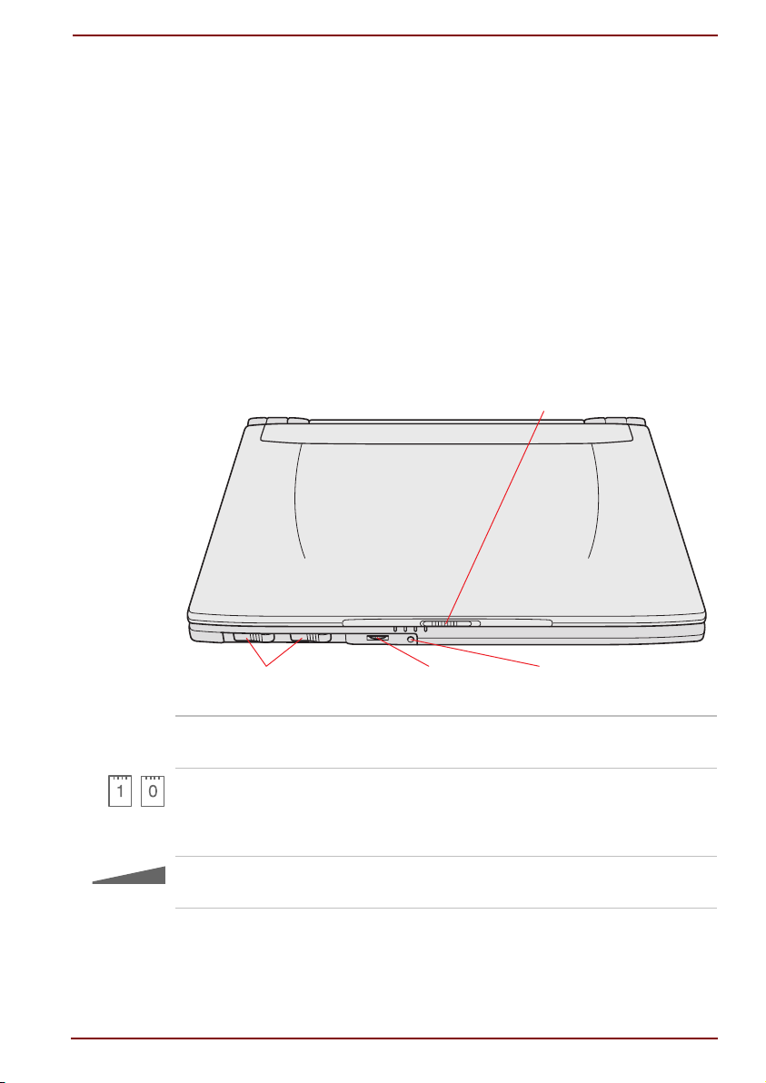
Front with display closed
This figure shows the computer’s front with its display panel in the
closed position.
DISPLAY LATCH
Front of the computer with display closed
Display latch
PC Card latches
Volume control
User's Manual The Grand Tour 2-1
This latch secures the LCD panel in its closed
position. Slide the latch to open the display.
When you install a PC Card, the corresponding
latch (left latch, slot “1”; right latch slot “0”) locks
into place. Refer to the PC Card section in
Chapter 8, Optional Devices
Use this dial to adjust the volume of the system
speaker and headphones.
RESETVOLUME CONTROLPC CARD LATCHES
.
Page 28
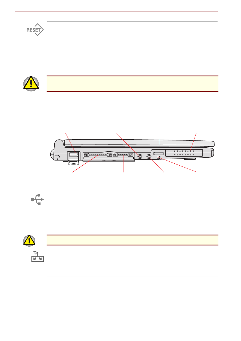
Left side
Reset
Press the reset button to reset the computer
when it does not respond to keyboard
commands. Use a narrow object such as the tip
of a covered ball-point pen. The system restarts,
clearing all data in memory and overriding the
Resume feature. See Chapter 6, Power and
Power-Up Modes, for more information on the
reset switch and Resume.
Do not use a pencil to push the reset button. Pencil lead can break off
inside the computer and damage its circuitry.
This figure shows the computer’s left side.
USB PORT MICROPHONE JACK
I/O ADAPTOR PORT
EXTERNAL DISKETTE
The left side of the computer
Universal Serial Bus
port
A rubber cover protects the Universal Serial Bus
(USB) port, which enables chain connection of a
DRIVE PORT
POWER SWITCH PC CARD SLOT
HEADPHONE
JACK
POWER
SWITCH LOCK
number of USB-equipped devices to one port on your
computer. For example, you might connect a USBHUB to the computer, then connect a keyboard to the
USB-HUB and a mouse to the keyboard.
Do not pull forcefully on the USB port cover.
Port Replicator port
This port lets you attach an Port Replicator that
enables connection of parallel and serial devices
and a PS/2 mouse or keyboard. It is protected by
a plastic cover.
2-2 The Grand Tour User's Manual
Page 29
External diskette
drive port
This port allows you to connect the 3 ½" external
diskette drive supplied with your computer. See
Chapter 3, Getting Started, for details. It is
protected by a plastic cover.
Keep foreign objects out of the diskette drive port. A pin or similar object
can damage the computer’s circuitry.
Microphone jack
A standard 3.5 mm mini microphone jack
enables connection of a monaural microphone or
other device for audio input. When you connect
an external microphone, the internal microphone
is automatically disabled.
Headphone jack
A standard 3.5 mm mini headphone jack enables
connection of a stereo headphone (16 ohm
minimum) or other device for audio output. When
you connect headphones, the internal speaker is
automatically disabled.
Power switch
Press the power button to turn the computer’s
power on and off.
Power switch lock
Set this lock to the locked position to prevent
inadvertent power on.
PC Card slot
A PC Card slot can accommodate two 5 mm
PC Card (Type II) or one 10.5 mm PC Card
(Type III). You can install any industry standard
PC Card such as a modem, SCSI adaptor,
Ethernet adaptor or flash memory card. A
dummy card is installed to protect the slot.
Keep foreign objects out of the PC Card Slot. A pin or similar object can
damage the computer’s circuitry.
User's Manual The Grand Tour 2-3
Page 30
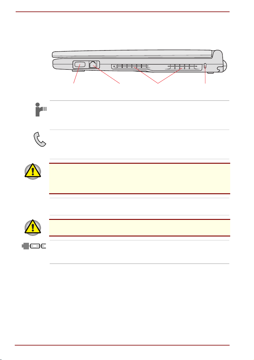
Right side
The following illustration shows the computer’s right side.
The right side of the computer
Infrared port
Modem jack
In case of a lighting storm, unplug the modem cable from the
telephone jack.
Do not connect the modem to a digital telephone line. A digital line will
damage the modem.
Fan vents
Be careful not to block the fan vent. Also be careful to keep foreign objects out
of it. A pin or similar object can damage the computer’s circuitry.
Security lock slot
This infrared port is compatible with Infrared Data
Association (IrDA) Fast InfraRed (FIR) standards. It
enables cableless 4 Mbps data transfer with IrDA
1.1 compatible external devices.
The modem jack lets you use a modular cable to
connect the modem directly to a telephone line.
The modem is not supported in some
marketing regions.
Vents provide air-flow paths for the fan to prevent
the CPU from overheating.
A security cable attaches to this slot. The
optional security cable anchors your computer to
a desk or other large object to deter theft.
SECURITY LOCK SLOTINFRARED PORT MODEM JACK FAN VENTS
2-4 The Grand Tour User's Manual
Page 31

Back side
This illustration shows the computer’s back panel.
FAN VENTS
EXTERNAL MONITOR PORT
DC IN 15V
Battery pack
External monitor port
Fan vents
BATTERY PACKDC IN 15V
The computer’s back side
The AC adaptor’s DC output plug connects to
this socket. Use only the model of AC adaptor
that comes with the computer. Using the wrong
adaptor can damage your computer.
The battery pack powers the computer when the
AC adaptor is not connected. The Batteries
section in Chapter 6, Power and Power-Up
Modes, describes how to access the battery pack.
Additional battery packs, including high-capacity
models, can be purchased from your Toshiba
dealer to extend the computer’s battery operating
time.
This 15-pin port lets you connect an
external monitor.
Refer to the section
Right side
.
User's Manual The Grand Tour 2-5
Page 32

Underside
The following picture shows the underside of the computer. Make sure the
display is closed before turning over your computer.
BATTERY LOCKBATTERY PACKBATTERY RELEASE LATCH
EXPANSION
MEMORY SOCKET
FANVENT
DOCKING
PORT
Battery pack
Battery release latch
DOCKING HOLES
Described in the section, Back side
Press this release to free the battery for removal.
.
For directions on removing the battery pack,
refer to Chapter 6, Power and Power-Up Modes.
Battery lock
A sliding lock prevents inadvertent release of the
battery pack.
Docking port
Use this port to connect an optional
DVD Network Dock II.
Keep foreign objects out of the docking interface port. A pin or similar
object can damage the computer’s circuitry.
Docking holes
These holes ensure a proper connection
between the computer and an optional
DVD Network Dock II.
Expansion memory
socket
Use this socket to install a memory module to
increase your computer’s memory by 32, 64 or
128 MB. Use only memory modules that are
compatible with the computer. Refer to the
Fan vent
Memory expansion
Optional Devices
Refer to the section
section in Chapter 8,
.
Right side
.
2-6 The Grand Tour User's Manual
Page 33

Front with the display open
The front of the computer with the display open is shown in the figure
below. To open the display, slide the display latch on the front of the
computer and lift the display up. Position the display at a comfortable
viewing angle.
KEYBOARD
INDICATORS
MICROPHONE
ACCUPOINT II
The front with the display open
SPEAKER
DISPLAY SCREEN
COOLING VENT
SCROLL BUTTONS
CONTROL BUTTONS
POWER SOURCE/
SYSTEM INDICATORS
ACCUPOINT II
PANEL POWER
ON/OFF SWITCH
Scroll buttons
These buttons are used to scroll windows.
The left button scrolls up; the right button
scrolls down.
Display screen
The full-colour LCD displays high-contrast text
and graphics and is compatible with the industry
standard Video Graphics Array (VGA). The LCD
consists of up to 1024 x 768 pixels or dots. The
computer has a Thin-Film Transistor (TFT)
display. Refer to Appendix E.
When the computer operates on power through
the AC adaptor, the display screen’s image will
be somewhat brighter than when it operates on
battery power. The lower brightness level is
intended to save battery power.
User's Manual The Grand Tour 2-7
Page 34

AccuPoint II
A pointer control device located in the centre of
the keyboard is used to control the on-screen
pointer. Refer to the AccuPoint II section in
Chapter 4, Operating Basics.
AccuPoint II control
buttons
Power source/
system indicators
Keyboard indicators
Speaker
Microphone
Panel power on/off
switch
Cooling vent
Control buttons below the keyboard let you select
menu items or manipulate text and graphics
designated by the on-screen pointer.
LEDs let you monitor the status of various
computer functions. Details are given in the
Indicators section.
The keyboard indicators provide icons to let you
monitor the caps lock, arrow mode and numeric
mode functions. Details are given later in
this chapter.
The speaker emits sound generated by your
software as well as audio alarms, such as low
battery condition, generated by the system.
A microphone lets you record sound into
your applications.
When the computer is in Resume (Suspend or
Standby) mode and the panel power on/off
feature is enabled, this switch turns on power to
the computer when you open the display and
turns it off when you close the display. It is
located in the panel latch. You should not
depress this switch except by closing the
display panel.
Provides an intake of air pulled through the
computer by the fan.
Be careful not to block the cooling vent. Also be careful to keep foreign objects
2-8 The Grand Tour User's Manual
out of it. A pin or similar object can damage the computer’s circuitry.
Page 35

Indicators
The next two illustrations show the indicators, which light when various
computer operations are in progress.
Power source/system indicators
DC IN POWER BATTERY DISK
On
DC IN
Power
The
Resume
Standby
Battery
Built-in HDD
mode is called
in Windows 98. The functions are essentially the same.
DC IN
The
is supplied from the AC power adaptor. If the
adaptor’s output voltage is abnormal or if the
power supply malfunctions, this indicator flashes
orange.
The
computer is on. If you turn off the computer in
Resume mode, this indicator blinks orange (one
second on, two seconds off) while the computer
shuts down.
The battery indicator shows the condition of the
charge. Green means fully charged and orange
means being charged. Refer to Chapter 6, Power
and Power-Up Modes.
This indicator glows green when the computer is
accessing the built-in HDD.
indicator glows green when DC power
Power
indicator glows green when the
Suspend/Resume
in Windows 95 and
User's Manual The Grand Tour 2-9
Page 36

Keyboard indicators
Caps Lock
Arrow mode
Numeric mode
The keyboard indicators
NUMERIC MODEARROW MODECAPS LOCK
This indicator glows green when the alphabet
keys are locked in uppercase.
When the
Arrow mode
indicator lights green, you
can use the keypad overlay (grey-labelled keys) as
cursor keys. Refer to the Numeric keypad overlay
section in Chapter 5, The Keyboard.
You can use the keypad overlay (grey-labelled
keys) for numeric input when the
Numeric mode
indicator lights green. Refer to the Keypad overlay
section in Chapter 5, The Keyboard.
2-10 The Grand Tour User's Manual
Page 37

Port Replicator
The Port Replicator enables connection of parallel and serial devices and
a PS/2 mouse or keyboard. See Chapter 3, Getting Started, for details on
connecting the Port Replicator.
COMPUTER
CONNECTOR
PS/2 MOUSE/
KEYBOARD PORT
PS/2 mouse or
keyboard port
Serial port
Parallel port
Computer connector
SERIAL PORT PARALLEL PORT
The Port Replicator
Use this port to connect an external PS/2
compatible mouse or keyboard. The computer
automatically recognises which device is
connected when you turn on the power.
Use this 9-pin port to connect external serial
devices such as an external modem, a serial
mouse or a serial printer.
Use this Centronics-compatible, 25-pin parallel
port to connect a parallel printer or other parallel
device. This port supports Extended Capabilities
Port (ECP) standard.
This connects the Port Replicator to the computer.
User's Manual The Grand Tour 2-11
Page 38

AC adaptor
The AC adaptor converts AC power to DC power and reduces the voltage
supplied to the computer. It can automatically adjust to any voltage from
100 to 240 volts and to a frequency of either 50 or 60 hertz, enabling you
to use the computer in almost any country.
To recharge the battery, simply connect the AC adaptor to a power source
and the computer. See Chapter 6, Power and Power-Up Modes, for
details.
Use of the wrong adaptor could damage your computer. Toshiba assumes
no liability for any damage in such case. The current rating for the
computer is 3.0 amperes.
TSHI
The AC adaptor
2-12 The Grand Tour User's Manual
Page 39

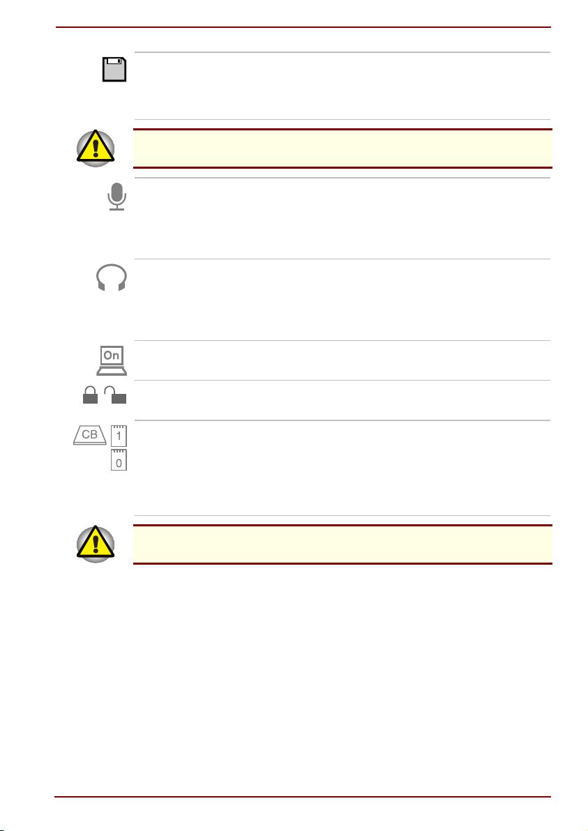
3 ½" diskette drive
The 3 ½" external diskette drive module can be connected to the external
diskette drive port. The drive comes with a special cable that connects to
the dedicated 3 ½" drive connector. See Chapter 3, Getting Started, for
details on connecting and using the diskette drive.
DISKETTE DRIVE CONNECTOR
(NOT SHOWN)
DRIVE CONNECTOR
DISK-IN-USE
INDICATOR
Eject button
EJECT BUTTON
DISKETTE SLOT
COMPUTER CONNECTOR
The 3 ½" diskette drive
When a diskette is fully seated in the drive, the
eject button pops out. To remove a diskette, push
in the eject button and the diskette pops out
partially for easy removal.
Diskette slot
Disk-In-Use Indicator
Insert diskettes in this slot.
This indicator lights when the diskette is
being accessed.
Check the disk indicator when you use the diskette drive. Do not press the
eject button, disconnect a drive cable or turn off the computer while the
light is glowing. Doing so could destroy data and damage the diskette or
the drive.
Diskette drive
A special cable connects this port to the computer.
connector
User's Manual The Grand Tour 2-13
Page 40

2-14 The Grand Tour User's Manual
Page 41

Chapter 3
Getting Started
This chapter provides basic information to get you started using your
computer. It covers the following topics:
Setting up your work space — for your health and safety
Connecting the AC adaptor
Using the Port Replicator
Using the external diskette drive
Opening the display
Turning on the power
Selecting an operating system
Turning off the power
Restarting the computer
Restoring the preinstalled software
All users should be sure to carefully read the section
operating system
preinstalled operating systems (OS), which is the first thing you must do
after turning on the power.
. This section explains how to select one of the two
Selecting an
Setting up
Establishing a comfortable work site is important for you and your
computer. A poor work environment or stressful work habits can result in
discomfort or serious injury from repetitive strain to your hands, wrists or
other joints. Proper ambient conditions should also be maintained for the
computer’s operation. This section discusses the following topics:
General conditions
Placement of the computer and peripheral devices
Seating and posture
Lighting
Work habits
User's Manual Getting Started 3-1
Page 42

General conditions
In general, if you are comfortable, so is your computer, but read the
following to make sure your work site provides a proper environment.
Make sure there is adequate space around the computer for
proper ventilation.
Make sure the AC power cord connects to an outlet that is close to the
computer and easily accessible.
The temperature should be 5 to 35 degrees Centigrade (41 to 95
degrees Fahrenheit) and the relative humidity should be 20 to
80 percent.
Avoid areas where rapid or extreme changes in temperature or
humidity may occur.
Keep the computer free of dust, moisture, and exposure to direct sunlight.
Keep the computer away from heat sources, such as electric heaters.
Do not use the computer near liquids or corrosive chemicals.
Do not place the computer near objects that create strong magnetic
fields (e.g., stereo speakers).
Do not operate the computer in close proximity to a mobile phone.
Placement of computer
Position the computer and peripheral devices to provide comfort and safety.
Set the computer on a flat surface at a comfortable height and distance.
The display should be no higher than eye level to avoid eye strain.
Place the computer so that it is directly in front of you when you work
and make sure you have adequate space to easily operate other
devices.
Allow adequate space behind the computer to let you freely adjust the
display. The display should be angled to reduce glare and maximise
visibility.
If you use a paper holder, set it at about the same height and distance
as the computer.
3-2 Getting Started User's Manual
Page 43

Seating and posture
The height of your chair in relation to the computer and keyboard as well
as the support it gives your body are primary factors in reducing work
strain. Refer to the following tips and illustration.
1
Posture and positioning of the computer
Place your chair so that the keyboard is at or slightly below the level of
your elbow. You should be able to type comfortably with your
shoulders relaxed.
Your knees should be slightly higher than your hips. If necessary, use
a foot rest (see "1" in the above illustration) to raise the level of your
knees to ease pressure on the back of your thighs.
Adjust the back of your chair so it supports the lower curve of your spine.
Sit straight so that your knees, hips and elbows form approximately 90
degree angles when you work. Do not slump forward or lean back too
far.
User's Manual Getting Started 3-3
Page 44

Lighting
Proper lighting can improve legibility of the display and reduce eye strain.
Position the computer so that sunlight or bright indoor lighting does not
reflect off the screen. Use tinted windows, shades or other screen to
eliminate sun glare.
Avoid placing the computer in front of bright light that could shine
directly in your eyes.
If possible, use soft, indirect lighting in your computer work area. Use a
lamp to illuminate your documents or desk, but be sure to position the
lamp so that it does not reflect off the display or shine in your eyes.
Work habits
A key to avoiding discomfort or injury from repetitive strain is to vary your
activities. If possible, schedule a variety of tasks into your work day. If you
must spend long periods at the computer, finding ways to break up the
routine can reduce stress and improve your efficiency.
Sit in a relaxed posture. Good positioning of your chair and equipment
as described earlier can reduce tension in your shoulders or neck and
ease back strain.
Vary your posture frequently.
Occasionally stand up and stretch or exercise briefly.
Exercise and stretch your wrists and hands a number of times during
the day.
Frequently, look away from the computer and focus your eyes on a
distant object for several seconds, for example 30 seconds every
15 minutes.
Take frequent short breaks instead of one or two long breaks, for
example, two or three minutes every half hour.
Have your eyes examined regularly and visit a doctor promptly, if you
suspect you might be suffering from a repetitive strain injury.
A number of books are available on ergonomics and repetitive strain
injury or repetitive stress syndrome. For more information on these topics
or for pointers on exercises for such stress points as hands and wrists,
please check with your library or book vendor. Also refer to the computer’s
Safety Instruction Manual
.
3-4 Getting Started User's Manual
Page 45

Connecting the AC adaptor
Attach the AC adaptor when you need to charge the battery or you want to
operate from AC power. It is also the fastest way to get started, because
the battery pack will need to be charged before you can operate from
battery power.
The AC adaptor can be connected to any power source supplying from 100 to
240 volts and 50 or 60 hertz. For details on using the AC adapter to charge the
battery pack, refer to Chapter 6, Power and Power-Up Modes.
Use of the wrong adaptor could damage your computer. Toshiba assumes
no liability for any damage in such case. The current rating for the
computer is 3.0 amperes.
1.
Connect the power cord to the AC adaptor.
Connecting the power cord to the AC adaptor
2.
Connect the AC adaptor’s DC output plug to the
the back of the computer.
DC IN
input port on
Connecting the adaptor to the computer
3.
Plug the power cord into a live wall outlet. The
indicator on the front of the computer should glow.
User's Manual Getting Started 3-5
Battery
and
DC IN
Page 46

Using the Port Replicator
The Port Replicator provides ports to let you connect parallel and serial
devices and a PS/2 mouse or keyboard.
Hot docking is not supported for the Port Replicator.
Connecting the Port Replicator
To connect the Port Replicator, follow the steps below.
1.
Save your data, shut down Windows and turn off the power.
2.
Squeeze the latches on either side of the connector.
3.
Plug the connector into the computer's port. Press evenly to avoid
damaging the connector.
Aligning the connectors
Disconnecting the Port Replicator
To disconnect the Port Replicator follow the steps below.
1.
Save your data, shut down Windows and turn off the power.
2.
Squeeze the latches on either side of the connector.
3.
Pull the connector out of the computer's port.
4.
Pull out the connector holder and insert the connector to protect it
when the Port Replicator is not in use.
The Port Replicator's connector holder
3-6 Getting Started User's Manual
Page 47

Using the 3 ½" external diskette drive
Use the 3 ½" external diskette drive to transfer data to and from the
computer system and to and from the hard disk.
The external diskette drive should be placed on a flat, horizontal surface
when in use. Do not set the drive on an incline greater than 20o while it is
operating.
Do not set anything on top of the diskette drive.
Hot docking is not supported for the diskette drive.
Connecting the 3 ½" diskette drive
To connect the drive, follow the steps below and refer to the following two
illustrations.
1.
Save your data, shut down Windows and turn off the power.
2.
Plug the connecting cable’s larger connector into the 3 ½" external
diskette drive’s socket. Press the latches on either side of the
connector when you plug in the connector.
Make sure the connector is right side up and properly aligned with the
socket. Do not try to force the connection, doing so can damage the
connecting pins.
Connecting the cable to the diskette drive
3.
Open the cover of the 3 ½" diskette drive port.
User's Manual Getting Started 3-7
Page 48

4.
Press the latches on either side of the smaller connector and plug it
into the diskette drive port.
Connecting the diskette drive to the computer
When you use the diskette drive, connect the drive before you turn on the
computer. If the drive is connected after the computer is turned on, the
computer may not recognise the connection. In this case you must restart
the computer after the drive is connected.
Disconnecting the 3 ½" diskette drive
When you have finished using the diskette drive, follow the procedures
below to disconnect it:
1.
Save your data, shut down Windows and turn off the power.
2.
Wait for the indicator light to go out to make sure all diskette activity
has stopped.
If you disconnect the diskette drive or turn off the power while the
3-8 Getting Started User's Manual
computer is accessing the drive you may lose data or damage the
diskette or the drive.
3.
Press the release latches on either side of the connector attached to
the computer and pull out the connector.
4.
Close the cover to the diskette drive port.
5.
Press the release latches on either side of the connector attached to
the diskette drive and pull out the connector.
Page 49

Diskette care
Handle your diskettes with care. The following simple precautions will increase
the lifetime of your diskettes and protect the data you store on them:
1.
Store your diskettes in the container they came in to protect them and
keep them clean. If a diskette is dirty, do not use cleaning fluid. Clean
it with a soft damp cloth.
2.
Do not slide back the diskette’s protective metal covering or touch the
diskette’s magnetic surface. Fingerprints may prevent the diskette
drive from reading data from the diskette.
3.
Data may be lost if the diskette is twisted; bent; or exposed to direct
sunlight, extreme heat or cold.
4.
Do not place heavy objects on your diskettes.
5.
Do not eat, smoke, or use erasers near your diskettes. Foreign
particles inside the diskette’s jacket can damage the magnetic
surface.
6.
Magnetic energy can destroy the data on your diskettes. Keep your
diskettes away from speakers, radios, televisions and other sources of
magnetic fields.
Opening the display
The display panel can be rotated in a wide range of angles for
optimal viewing.
1.
Slide the display latch on the front of the computer to the right to
unlatch the display panel.
2.
Lift the panel up and adjust it to the best viewing angle for you.
Opening the display panel
User's Manual Getting Started 3-9
Page 50

Turning on the power
This section describes how to turn on the power.
After you turn on the power for the first time, do not turn it off until you have
selected an operating system (OS) and your selected OS has started up.
Refer to the section
1.
If the external diskette drive is connected, make sure it is empty. If a
diskette is in the drive, press the eject button and remove the diskette.
2.
Slide the power switch lock (illustrated below on the underside of the
computer) to its unlocked position, then press and hold the switch for
two or three seconds.
Selecting an operating system
in this chapter.
Turning on the power
If you turn on the computer in
3-10 Getting Started User's Manual
screen will appear as it was when the computer was turned off.
Standby, Suspend
or
Hibernation mode
, the
Page 51

Selecting an operating system
Two operating systems are installed on your computer’s hard disk:
Windows 95 and Windows 98. You must select one OS.
After your selection, the other OS will be permanently erased from
your system.
When you first turn on the power, the computer’s initial screen is the
Selecting OS Menu. Press the ‘1’ key to select Windows 98 and the ‘2’
key to select Windows 95. Follow the on-screen directions. After you
complete your selections, the system will boot in the OS you chose.
Be sure to read the
all the information in the
screen asks you to enter the product ID number.
The ID number is 20 figures for Windows 95 and 25 figures for
Windows 98. Enter the appropriate ID number into the Certificate of
Authenticity dialog box.
Be sure to read the License Agreement carefully.
License on Windows
Certificate of Authenticity
Turning off the power
The power can be turned off in one of three modes: Boot, Resume
(Standby/Suspend) or Hibernation.
display carefully. Also read
screen. This
It is better not to use the power switch to turn off the computer.
Boot mode
When you turn off the power in Boot mode no data is saved and the
computer will boot to the operating system’s main screen.
1.
If you have entered data, save it to the hard disk or to a diskette.
2.
Make sure all disk activity has stopped, then remove the diskette.
Make sure the
User's Manual Getting Started 3-11
being accessed, you can lose data or damage the disk.
3.
If you are using Windows 95, click
Shut down the computer?
4.
If you are using Windows 98, click
the
Shut Down
indicator is off. If you turn off the power while a disk is
Disk
Start
, click
Shut Down
and click
.
Shut Down
menu select
.
Start
Shut down
, then click
. From
Page 52

5.
If you are using MS-DOS, set the power-up mode to boot in TSETUP and
turn off the power. Refer to Chapter 7, Setup and Password Security.
6.
Turn off the power to any peripheral devices.
Do not turn the computer or devices back on immediately. Wait a moment
to let all capacitors fully discharge.
Resume (Standby/Suspend) mode
If you shut down the computer in Resume (Standby/Suspend) mode data
currently in memory will be saved in memory. When you turn the power back
on you can continue where you left when you turned off the computer.
1.
If you are using Windows 95, click
2.
If you are using Windows 98, click
the
Shut Down
3.
If you are using MS-DOS, set the power-up mode to Resume in
TSETUP and turn off the power. Refer to Chapter 8, Setup and
Password Security.
4.
Turn off the power to any peripheral devices.
Do not turn the computer or devices back on immediately. Wait a moment
to let all capacitors fully discharge.
menu select
Hibernation mode
If you shut down the computer in Hibernation mode, data currently in
memory will be saved to the hard disk. When you turn the power back on,
you can continue where you left when you turned off the computer.
Hibernation settings can be made in Power Saver Utility.
When you turn off the power in Hibernation mode, the computer takes a
moment to save current memory data to the hard disk. During this time the
Disk
indicator will light and the following window will be displayed.
Start
Start
Stand by
then click
and click
.
Suspend
Shut Down
.
. From
The hibernation window
Do not turn off the power while the memory content is being saved.
3-12 Getting Started User's Manual
After you turn off the computer and memory is saved to the hard disk, turn
off the power to any peripheral devices.
Do not turn the computer or devices back on immediately. Wait a moment
to let all capacitors fully discharge.
Page 53

Restarting the computer
Certain conditions require that you reset the system. For example, if:
You change certain computer settings.
An error occurs and the computer does not respond to your keyboard
commands.
There are four ways to reset the computer system:
1.
Select
Restart
2.
If the computer is already on, press
3.
If you’re experiencing a problem with a software application and the
computer does not accept keyboard input, press the reset button.
4.
Turn the power off, wait 10 to 15 seconds, then turn the power on
again by pressing the power button. (This method works only when the
computer is in boot mode.)
from the
Windows Shut Down
Restoring the preinstalled software
If preinstalled files are damaged, use the Product Recovery CD-ROM or
the Toshiba Tools & Utilities CD-ROM to restore them with the optional
DVD Network Dock II.
Restoring the complete system
To restore the operating system and all preinstalled software, follow the
steps below.
Ctrl
+
Alt
menu in the
Del
+
.
Start
box.
When you reinstall the Windows operating system, the hard disk will be
reformatted and all data will be lost. Make sure you have a backup copy
of your data, before you perform a complete system recovery.
To restore the operating system and all preinstalled software, you need to
use an optional DVD Dock or an external CD-ROM drive.
1.
Turn off the power.
2.
Connect the computer to an optional DVD Dock.
3.
Load the Product Recovery CD-ROM in the DVD-ROM drive.
4.
Hold down the C key and turn on the power. When
Tomorrow TOSHIBA
5. Follow the on-screen instructions.
appears, release the C key.
In Touch with
Restoring Toshiba utilities and drivers
If Windows is working properly, individual drivers or applications can be
separately restored. Use the Tools & Utilities CD-ROM according to
instructions in the booklet contained in the CD box to reinstall Toshiba
utilities and drivers.
User's Manual Getting Started 3-13
Page 54

3-14 Getting Started User's Manual
Page 55

Chapter 4
Operating Basics
This chapter gives information on basic operations including using
AccuPoint II, using the microphone and international modem, tips on
caring for your computer and heat dispersal.
Using AccuPoint II
To use the AccuPoint II, simply push it with your finger tip in the direction
you want to move the on-screen pointer.
ACCUPOINT II
SCROLL BUTTONS
ACCUPOINT II
CONTROL BUTTONS
AccuPoint II and control buttons
Two large buttons below the keyboard are used like the buttons on a mouse
pointer. Press a button to select a menu item or to manipulate text or graphics
designated by the pointer. The smaller buttons can be used to scroll windows.
The left button scrolls up, and the right button scrolls down.
User's Manual Operating Basics 4-1
Page 56

AccuPoint II precautions
Certain conditions can affect the on-screen pointer when using
AccuPoint II. For example, the pointer may travel contrary to AccuPoint II
operation or an error message may appear, if
You touch the AccuPoint II during power-up.
You apply constant, soft pressure during power-up.
There is a sudden temperature change.
Strong stress is applied to the AccuPoint II.
If an error message appears, reboot the computer. If an error message does
not appear, wait a moment for the pointer to stop, then continue operation.
Replacing the cap
The AccuPoint II cap is an expendable item that should be replaced after
prolonged use. There are spare AccuPoint II caps supplied with the computer.
1.
To remove the AccuPoint II cap, firmly grasp the cap and pull it straight
up.
ACCUPOINT II CAP
PEG
Removing the AccuPoint II cap
2.
Position a new cap on the peg and press it into place.
The peg is square, so be careful to align the cap’s square hole with the peg.
4-2 Operating Basics User's Manual
Page 57

Using the microphone
Your computer has a built-in microphone that can be used to record
monaural sounds into your applications. It can also be used to issue voice
commands to applications that support such functions.
Since your computer has a built-in microphone and speaker, “feedback”
may be heard under certain conditions. Feedback occurs when sound
from the speaker is picked up in the microphone and amplified back to the
speaker, which amplifies it again to the microphone.
This feedback occurs repeatedly and causes a very loud, high-pitched
noise. It is a common phenomenon that occurs in any sound system when
the microphone input is output to the speaker (throughput) and the
speaker volume is too loud or too close to the microphone.
You can control throughput by adjusting the volume of your speaker or
through the Mute function.
To adjust the volume or activate Mute, click the
Programs
Volume Control
bars to adjust the volume level or click
, point to
International modem
Read this section for directions on connecting the modem. Refer to the
online help files for the international modem and RingCentral for details
on operation of your modem and modem software.
The international modem does not support the voice functions described in the
Ring Central’s online help files. All data and fax functions are supported.
Accessories
. In the
Volume Control
, point to
Mute
Start
button, point to
Multimedia
panel, you can use the slide
at the bottom of the panel.
and click
In case of a lightning storm, unplug the modem cable from the telephone
User's Manual Operating Basics 4-3
jack.
Do not connect the modem to a digital telephone line. A digital line will
damage the modem.
Page 58

Country selection
Before connecting the modem, select the country in which you are
operating the modem. Follow the steps below.
1.
2.
3.
4.
If you are using the computer in Japan, technical regulations described in
the Telecommunications Business Law require that you select the Japan
country mode. It is illegal to use the modem in Japan with any other
selection.
Start
Click
Point to
Point to
Click
.
Programs
Toshiba Internal Modem
Country Select Utility
.
.
and follow the on-screen instructions.
Connecting
To connect the international modem cable, follow the steps below.
1.
Plug one end of the modular cable into the modem jack.
2.
Plug the other end of the modular cable into a telephone jack.
Connecting the international modem
Disconnecting
To disconnect the international modem cable, follow the steps below.
1.
Pinch the lever on the connector in the telephone jack and pull out the
connector.
2.
Disconnect the cable from the computer in the same manner.
4-4 Operating Basics User's Manual
Page 59

Cleaning the computer
To help assure long, trouble-free operation, keep the computer free of
dust and use care with liquids around the computer.
Be careful not to spill liquids into the computer. If the computer does
get wet, turn the power off immediately and let the computer dry
completely before you turn it on again.
Clean the computer using a slightly damp (with water) cloth. You can
use glass cleaner on the display. Spray a small amount of cleaner on
a soft, clean cloth and wipe the screen gently with the cloth.
Never spray cleaner directly onto the computer or let liquid run into any
part of it. Never use harsh or caustic chemical products to clean the
computer.
Moving the computer
The computer is designed for rugged durability. However, a few simple
precautions taken when moving the computer will help assure trouble-free
operation.
Make sure all disk activity has ended before moving the computer.
Check the
external disk drives.
Disconnect the AC adaptor, Port Replicator or DVD Dock, and all other
peripherals before moving the computer.
Turn off the power to the computer.
Close the display. Do not pick up the computer by its display panel or
back (where the interface ports are located).
Close all port covers.
Set the power switch lock to the lock position.
Use the carrying case when transporting the computer.
Disk
indicator on the computer and the indicators on any
User's Manual Operating Basics 4-5
Page 60

Heat dispersal
To protect from overheating, the CPU has an internal temperature sensor.
If the computer’s internal temperature rises to a certain level, the cooling
fan is turned on or the processing speed is lowered. If you use
Windows 95, you can set the
Power Mode Setup
select whether to control the CPU temperature by turning on the fan first,
then if necessary, lowering the CPU speed. Or, by lowering the CPU
speed first, then if necessary, turning on the fan. Use the
Power Save Mode
When the CPU temperature falls to a normal range, the fan is turned off
and the CPU operation returns to standard speed.
If the CPU temperature reaches an unacceptably high level with either
setting, the system automatically shuts down. In Windows 95, it shuts
down in Hibernation mode. In Windows 98, the mode depends on the
setting in Power Saver: Shutdown, Resume or Hibernation.
System
in Power Saver. If you use Windows 98, you can
Cooling Method
window in Power Saver.
in the
Fan
window of
item of the
4-6 Operating Basics User's Manual
Page 61

Chapter 5
The Keyboard
The computer’s keyboard layouts are compatible with a 101/102-key
enhanced keyboard. By pressing some keys in combination, all the
101/102-key keyboard functions can be executed on the computer.
The number of keys on your keyboard depends on which country’s
keyboard layout your computer is configured with. Keyboards for
numerous languages are available. These optional international keyboard
layouts are illustrated in Appendix D, Keyboard Layouts.
There are five types of keys typewriter keys, keypad overlay, function
keys, soft keys and cursor control keys. The typewriter keys and keypad
overlay keys are grey. The other keys are dark grey.
Typewriter keys
The typewriter keys, produce the upper- and lower-case letters, numbers,
punctuation marks, and special symbols that appear on the screen.
There are some differences, however, between using a typewriter and
using a computer keyboard:
Letters and numbers produced in computer text vary in width. Spaces,
which are created by a “space character,” may also vary depending on
line justification and other factors.
The lowercase l (el) and the number 1 (one) are not interchangeable
on computers as they are on a typewriter.
The uppercase O (oh) and the 0 (zero) are not interchangeable.
Caps Lock
The
uppercase while the shift lock on a typewriter places all keys in the
shifted position.
Shift
The
the same function as their typewriter counterparts but also have
special computer functions.
keys, the
function key locks only the alphabetic characters in
Tab
key, and the
BkSp
(backspace) key perform
User's Manual The Keyboard 5-1
Page 62

F1…F12 function keys
The function keys, not to be confused with Fn, are the 12 keys at the top
of your keyboard. These keys are dark grey, but function differently from
the other dark grey keys.
F1 F2 F3 F4 F5 F6 F7 F8 F9 F10
F1
through
F12
are called function keys because they execute programmed
functions when pressed. Used in combination with the
with icons execute specific functions on the computer. See the section, Soft
keys: Fn key combinations, in this chapter. The function executed by individual
keys depends on the software you are using.
Soft Keys: Alt Gr Key Combinations
Alt Gr
Alt Gr
The
other keys to create accented or special characters (#,@,|, etc.). Note that
some of the keys bear three symbols (not to be confused with the blue or
white letters on the side of some other keys). To generate the third
symbol, hold
create. Please note that since the
American keyboard, it cannot be used if you have installed an American
keyboard driver in MS-DOS or Windows.
The euro symbol
By pressing
keyboards) you can generate the Euro symbol. Windows 98 supports the
Euro symbol natively. On Windows 95 and NT, only Arial, Times New
Roman and Courier New fonts have the Euro symbol implemented.
Please look at Microsoft web pages for newer patches and updates.
key, at the right of the space bar, is used in combination with
Alt Gr
and press the key bearing the character you wish to
Alt Gr
Alt Gr
+ e (
Alt Gr
+ 5,
Alt Gr
F11 F12
Fn
key, keys marked
key is not present on the
Alt Gr
+ 4 or
+ u on some
You may need to update the fonts on your printer to be able to print the
5-2 The Keyboard User's Manual
Euro symbol properly.
Page 63

Soft keys: Fn key combinations
The Fn (function) is unique to Toshiba computers and is used in
combination with other keys to form soft keys. Soft keys are key
combinations that enable, disable or configure specific features.
Some software may disable or interfere with soft-key operations. Soft-key
settings are not restored by the
Emulating keys on enhanced keyboard
Esc
F1
F3 F4 F5 F6 F7 F8 F9 F10 F11 F12
F2
~
`
Tab
CapsLock
Shift
Ctrl
The keyboard is designed to provide all the features of the 101-key
enhanced keyboard, shown in the previous figure. The 101/102-key
enhanced keyboard has a numeric keypad and scroll lock key. It also has
additional
Since the keyboard is smaller and has fewer keys, some of the enhanced
keyboard functions must be simulated using two keys instead of one on
the larger keyboard.
Your software may require you to use keys that the keyboard does not
have. Pressing the
enhanced keyboard’s functions.
#
!
1
QW RTYU I OP
$4%
@
2
3
E
ASDFGHJ KL
Alt
^
68
5
CXZB
V
A 101-key enhanced keyboard layout
Enter
Ctrl
,
and
Fn
key and one of the following keys simulates the
Resume (Suspend or Standby)
(9 )
&
*
7
<
MN
,
Alt
keys to the right of the main keyboard.
feature.
Pause
PrtSc
Scroll
SysReg
Break
lock
_
+
Bk Sp
Ins
-
0
=
{[}
\
]
,,
:
Enter
,
;
?
>
.
Shift
/
Alt
Ctrl
Home
Del
End
Num
PgUp
PgDn
*
/
.
Lock
7
8 9
Home
PgUp
+
654
3
1
2
PgDn
End
0
Ins
Enter
.
Del
Fn
F10
+
Fn
F11
+
Press
Fn + F10
Fn + F11
or
to access the integrated keypad. When
activated, the dark grey keys with grey markings on the bottom edge
become numeric keypad keys (
Fn + F10
(
). Refer to the Keypad overlay section in this chapter for more
Fn + F11
) or cursor control keys
information on how to operate these keys. The power on default for both
settings is off.
Fn
F12
+
Fn + F12 (ScrLock)
Press
to lock the cursor on a specific line. The power
on default is off.
User's Manual The Keyboard 5-3
Page 64

Fn
+
Fn + Enter
Press
numeric keypad.
Enter
to simulate
Enter
on the enhanced keyboard’s
Hot keys
Fn
Ctrl
+
Press
Fn
Fn + Ctrl
Alt
+
to simulate the enhanced keyboard’s right
Ctrl
key.
Press
Fn + Alt
to simulate the enhanced keyboard’s right
Alt
key.
Hotkeys (Fn + a function or cursor key) let you enable or disable certain
features of the computers.
Fn
Esc
+
Display Brightness:
Pressing
Fn + Esc
in a Windows 98 environment
changes the Display Brightness menu. When you press these hotkeys,
the current setting will be displayed in a window. These hotkeys work only
in Windows 98. You can also change this setting through the
brightness
item of the
In Windows 95, use the
Power Save Mode
Display Auto Off
window in Power Saver.
window in Windows 95 Power
Monitor
Saver utility to set the display brightness level.
Fn
F1
+
Instant security:
Press
Fn + F1
to lock the keyboard and blank the
screen to prevent others from accessing your data. To restore the screen
and original settings, enter the password. If no password is set, press
Enter
or F1.
Fn
F2
+
Battery save mode:
If you press
Fn + F2
Pressing
in a Windows 95 environment, an icon panel is
displayed showing the setting. If you press
Fn + F2
changes the battery save mode.
Fn + F2
in a Windows 98
environment, the Power Save Mode is displayed. When you press these
hotkeys, the current setting will be displayed in a window. You can also
change this setting through the
Power Saver Properties
the
5-4 The Keyboard User's Manual
Plugged in
window in Power Saver.
Running on batteries
or
item of
Page 65

Fn
F3
+
Power up mode:
Pressing
Fn + F3
changes the power up mode. When
you press these hotkeys, the current setting will be displayed in a window.
If you use Windows 95, you can use the
Setup in Power Saver. In a Windows 98 environment, use the
press the power button
feature of
System
window of Power Mode
System Power Mode
When I
window in Power
Saver. In Windows 98, this function changes the power up mode only
when you start the computer by pressing the power button.
Fn
F4
+
Alarm volume:
medium or high. The first time you press
Continue holding down
Press
Fn + F4
Fn
and press
to adjust the alarm volume to off, low,
Fn + F4
F4
again to change the setting. A
the volume is set to off.
beep sounds to let you know the current alarm volume. The volume at
power on depends on the latest setting. See Chapter 7, Setup and
Password Security.
Fn
F5
+
Display selection:
Pressing
Fn + F5
changes the active display device.
As indicated below, the changes depend on the computer’s display type,
current setting and whether you have a DVD Network Dock II or
CD Network Dock connected.
No DVD Dock
LCD only Ö LCD/CRT Ö CRT only Ö (back to LCD only)
DVD Dock connected
LCD only Ö LCD/CRT Ö CRT only Ö LCD/TV Ö TV only Ö (back to LCD only)
The LCD/TV setting can be selected only when the computer is in
Different Refresh Rate mode. Use the display setting feature in Windows
to set the mode.
User's Manual The Keyboard 5-5
Page 66

Windows 95/98 special keys
The keyboard provides two keys that have special functions in
Windows 95/98: one activates the
same function as the secondary mouse button.
This key activates the Windows 95/98
This key has the same function as the secondary mouse button.
Emulating Fn key on external keyboard
Fn
The
attached to the computer, you can execute
emulating the
Ctrl
and Password Security, for details on setting the Fn key equivalent.
key is only on Toshiba keyboards. If you use an external keyboard
Fn
key. For example, you might hold down
then press
F3
to change the power up mode. See Chapter 7, Setup
Keypad overlay
Your computer’s keyboard does not have an independent numeric
keypad, but its numeric keypad overlay functions like one.
The keys in the centre of the keyboard with light grey letters make up the
numeric keypad overlay. The overlay provides the same functions as the
numeric keypad on the 101/102-key enhanced keyboard in the next figure.
Start
Start
menu and the other has the
menu.
Fn
key combinations by
left Shift
+
left
Turning on the overlays
The numeric keypad overlay can be used for numeric data input or cursor
and page control.
Arrow mode
To turn on the Arrow mode, press
Now try cursor and page control using the keys shown in the next figure.
Fn + F10
Press
5-6 The Keyboard User's Manual
again to turn off the overlay.
Fn + F10 (Arrow mode
indicator lights).
Page 67

Numeric mode
To turn on the Numeric mode, press
lights). Now try numeric data entry using the keys in the next figure. Press
Fn + F11
again to turn off the overlay.
Fn + F11 (Numeric mode
indicator
∗
8
790
Home PgUp
7
()&
89
∗
UI OP
456
JKL
-
:
;
123
End PgDn
M
+
>
.
0
Ins Del
Esc
F1 F2 F3 F4 F5 F6 F7 F8 F9 F10
!
@
2
1345790
QW RT YU I OP
ASDFGHJKL
Caps
Lock
Shift
Fn
#
Alt AltCtrl
$%
E
()&
^
68
∗
Home PgUp
89
7
456
End PgDn
123
MNVCXZB
Ins Del
0
<
,
~
`
F11 F12
∗
:
;
>
.
. /
Ins
. /
_
-
{}
[]
-
"
´
+
?
/
Del
Prt Sc
Sys Req
+
=
The numeric keypad overlay
Temporarily using normal keyboard (overlay on)
While using the overlay, you can temporarily access the normal keyboard
without turning off the overlay:
1.
2.
3.
Fn
Hold
and press any other key. All keys will operate as if the overlay
were off.
Type upper-case characters by holding
character key.
Release
Fn
to continue using the overlay.
Fn + Shift
and pressing a
?
/
Pause
Break
BkSp
Home
PgUp
\
Enter
PgDn
EndShift
User's Manual The Keyboard 5-7
Page 68

Temporarily using overlay (overlay off)
While using the normal keyboard, you can temporarily use the keypad
overlay without turning it on:
1.
Press and hold down Fn.
2.
Check the icon panel. Pressing
overlay. If the
for numeric entry. If the
cursor and page control.
3.
Release
Numeric mode
Fn
to return to normal keyboard operation.
Arrow mode
Temporarily changing modes
If the computer is in
mode
by pressing a shift key.
If the computer is in
mode
by pressing a shift key.
Numeric mode
Arrow mode
Generating ASCII characters
Not all ASCII characters can be generated using normal keyboard
operation. But, you can generate these characters using their ASCII codes.
With the overlay on:
1.
Hold down
2.
Using the overlay keys, type the ASCII code.
3.
Release
With the overlay off:
1.
Hold
2.
Using the overlay keys, type the ASCII code.
3.
Release
A list of ASCII characters with their codes is shown in Appendix G.
Alt
.
Alt
, and the ASCII character appears on the display screen.
Alt + Fn
.
Alt + Fn
, and the ASCII character appears on the display screen.
Fn
turns on the most recently used
indicator lights, you can use the overlay
indicator lights, you can use it for
, you can switch temporarily to
, you can switch temporarily to
Arrow
Numeric
5-8 The Keyboard User's Manual
Page 69

Chapter 6
Power and Power-Up Modes
The computer’s power resources include the AC adaptor and internal
batteries. This chapter gives details on making the most effective use of
these resources including charging and changing batteries, tips for saving
battery power, and power up modes.
Power conditions
The computer’s operating capability and battery charge status are affected
by the power conditions: whether an AC adaptor is connected, whether a
battery is installed and what the charge level is for the battery.
Table 6-1 Power conditions
Power on Power off (no operation)
AC adaptor
connected
AC adaptor
not
connected
Battery fully
charged
Battery partially
charged or no
charge
No battery installed • Operates
Battery charge is
above low battery
trigger point
Battery charge is
below low battery
trigger point
Main battery charge
exhausted
No battery installed • No operation
• Operates
• Trickle charge
• LED:
• Operates
• Quick charge
• LED:
• No charge
• LED:
• Operates
• LED:
• Operates
• Alarm sounds
• LED:
orange
Computer goes into Resume
mode and shuts down
• LED:
Battery
DC IN
Battery
DC IN
Battery
DC IN
Battery
DC IN
Battery
DC IN
Battery
DC IN
• Trickle charge
• LED:
green
green
• Quick charge
• LED:
orange
green
• No charge
• LED:
off
green
off
off
flashes
off
off
off
Battery
DC IN
Battery
DC IN
Battery
DC IN
—
—
—
—
green
green
orange
green
off
green
User's Manual Power and Power-Up Modes 6-1
Page 70

Power indicators
As shown in the previous table, the
alert you to the computer’s operating capability and battery charge status.
Battery indicator
The following indicator lights indicate the battery status:
Flashing orange
Orange
Green
No light
If the battery becomes too hot while it is being charged, the charge will
stop and the battery indicator will go out. When the battery’s temperature
falls to a normal range, charge will resume. This event occurs regardless
of whether the power to the computer is on or off.
DC IN indicator
Check the
AC adaptor connected:
Battery, DC IN
The battery charge is low. The AC adaptor must
be connected to recharge the battery.
Indicates the AC adaptor is connected and
charging the battery.
Indicates the AC adaptor is connected and the
battery is fully charged.
Under any other conditions, the indicator does
not light.
DC IN
indicator to determine the power status with the
and
Power
indicators
Green
Flashing orange
No light
6-2 Power and Power-Up Modes User's Manual
Indicates the AC adaptor is connected and
supplying proper power to the computer.
Indicates a problem with the power supply or
overheating of the CPU. Plug the AC adaptor into
another outlet. If the indicator still flashes, there
could be a problem with the internal converter or
the internal temperature is too high. Let the
computer cool to room temperature. If it still does
not operate properly, see your dealer.
Under any other conditions, the indicator does
not light.
Page 71

Power indicator
Check the
Power
indicator to determine the power status:
Green
Blinking orange
The
Standby
No light
Battery types
The computer has three types of batteries:
Battery pack
Real Time Clock (RTC) battery
Optional high-capacity battery pack (described in Chapter 8, Optional
Devices)
Battery pack
When the AC power cord is not connected, the computer’s main power
source is a removable lithium ion battery pack, also referred to in this
manual as the battery. You can purchase additional battery packs for
extended use of the computer away from an AC power source.
The battery recharges the RTC battery and maintains the state of the
computer when you enable Resume.
Indicates power is being supplied to the
computer and the computer is turned on.
Indicates the power was turned off while the
computer was in Resume (Suspend or Standby)
mode. The indicator turns on for one second and
turns off for two seconds.
Resume
mode is called
in Windows 98. The functions are essentially the same.
Suspend/Resume
Under any other conditions, the indicator does
not light.
in Windows 95 and
The battery pack is a lithium ion battery, which can explode if not properly
User's Manual Power and Power-Up Modes 6-3
replaced, used, handled or disposed of. Dispose of the battery as required
by local ordinances or regulations. Use only batteries recommended by
Toshiba as replacements.
Page 72

Real Time Clock battery
The Real Time Clock (RTC) battery provides power for the internal real
time clock and calendar. It also maintains the system configuration.
If the RTC battery becomes completely discharged, the system loses this
data and the real time clock and calendar stop working. The following
message appears when you turn on the power:
*** Bad RTC battery ***
Check system. Then press [F1] key . . . . .
The computer’s RTC battery is a nickel metal hydride (NiMH) battery and
should be replaced only by your dealer or by a Toshiba service
representative. The battery can explode if not properly replaced, used,
handled or disposed of. Dispose of the battery as required by local
ordinances or regulations.
Care and use of the battery pack
The battery pack is a vital component of portable computing. Taking
proper care of it will help ensure longer operating time on battery power
as well as a longer life for your battery pack. Follow the instructions in this
section carefully to ensure safe operation and maximum performance.
Safety precautions
1.
Be very careful not to short-circuit the battery pack. Contacting both
terminals with a metal object can cause injury, fire or damage to the
battery pack.
2.
Do not overcharge, reverse charge, mutilate or disassemble the
battery. Any one of those actions could release toxic materials,
hydrogen and/or oxygen or other electrolytic substances or cause an
increase in the battery’s surface temperature.
3.
Do not expose the battery pack to fire; the battery pack could explode.
4.
Battery packs contain toxic substances. Do not dispose of them with
ordinary trash. Dispose of battery packs only in accordance with local
ordinances. Always cover the metal terminals with insulating tape to
avoid short circuits.
5.
If the battery has leaked or been vented, it should be replaced
immediately. Use protective gloves when handling a damaged battery.
6.
When it becomes necessary to replace the battery, it must be replaced
only by an identical battery from the same manufacturer.
6-4 Power and Power-Up Modes User's Manual
Page 73

7.
Do not expose the battery pack terminals to any metal object other
than the computer contacts. Wrap it or place it in a plastic bag when
transporting it.
8.
When you install the battery pack, you should hear a click when it is
seated properly.
9.
Charge the battery pack only in the computer or in a battery charger
designated as an approved option.
10.
Reverse polarity should be avoided with all batteries. The battery is
designed so that it cannot be installed in reverse polarity.
Charging the batteries
When the power in the battery pack becomes low, the
flashes orange indicating that only a few minutes of battery power remain.
If you continue to use the computer while the
the computer enables Hibernation mode (so you don’t lose data) and
automatically turns off.
You must recharge a battery pack when it becomes discharged.
Procedures
To recharge a battery pack while it is installed in the computer, connect
the AC adaptor to the
outlet.
Battery
The
Use only the computer connected to an AC power source or the optional
Toshiba Battery charger to charge the battery pack. Do not attempt to
charge the battery pack with any other charger.
indicator glows orange when the battery is being charged.
Battery
Battery
DC IN
socket and plug the other end into a working
indicator flashes,
indicator
Time
The following table shows the time required to fully charge a
discharged battery.
Charging time (hours)
Battery type Power on Power off
Battery pack (PA3000U) 4 to 10 2.5
High capacity battery pack
(PA3002U)
RTC battery 40 Doesn't charge
Refer to Chapter 8, Optional Devices, for information on the power
capacity of the battery packs.
User's Manual Power and Power-Up Modes 6-5
8 to 20 5
Page 74

Battery charging notice
The battery may not charge right away under the following conditions:
The battery is extremely hot or cold. If the battery is extremely hot, it
might not charge at all. Also, to ensure the battery charges to its full
capacity, charge the battery at room temperature of 10° to 30°C (50° to
88°F).
The battery is nearly completely discharged. Leave the AC adaptor
connected for a few minutes and the battery should begin charging.
Battery
The
time when you try to charge a battery under the following conditions:
The battery has not been used for a long time.
The battery has completely discharged and been left in the computer
for a long time.
A cool battery is installed in a warm computer.
In such case, follow the steps below.
1.
Fully discharge the battery by leaving it in the computer with the power
on until the power automatically shuts off.
2.
Plug in the AC adaptor.
3.
Charge the battery until the
Repeat the steps two or three times until the battery recovers normal capacity.
indicator may show a rapid decrease in battery operating
Battery
indicator shows green.
Monitoring battery capacity
Remaining battery power can be monitored by the Power Saver Utility
program.
Wait at least 16 seconds after the computer has completed start-up
6-6 Power and Power-Up Modes User's Manual
before trying to monitor the remaining operating time. The computer
needs this time to check the battery’s remaining capacity and to calculate
the remaining operating time, based on the current power consumption
rate and remaining battery capacity. The actual remaining operating time
may differ slightly from the calculated time.
With repeated discharges and recharges, the battery’s capacity will
gradually decrease. Therefore, an often used, older battery will not
operate for as long as a new battery even when both are fully charged. In
this case, Power Saver Utilities will indicate a 100% charge for both the
old and new battery, but the displayed estimated time remaining will be
shorter for the older battery.
Page 75

Maximising battery operating time
A battery’s usefulness depends on how long it can supply power on a
single charge.
How long the charge lasts in a battery depends on:
How you configure the computer, for example, whether you enable batterypower saving options. The computer provides a battery save mode to
conserve battery power. This mode has the following options:
•
Processing speed
•
HDD auto off
•
LCD Brightness
See Chapter 7, Setup and Password Security.
How often and how long you use the hard disk and the diskette drive.
How much charge the battery contained to begin with.
How you use optional devices, such as a PC card, to which the battery
supplies power.
Enabling Resume (Suspend/Standby) mode conserves battery power
if you are frequently turning the computer off and on.
Enabling Hibernation mode conserves battery power more effectively
than Resume (Suspend/Standby) mode, if you leave the computer off
for longer intervals. Resume mode requires battery power to maintain
data in memory, but Hibernation mode does not. However, Resume
mode is faster and requires less power to startup when you turn on the
computer.
Where you store your programs and data.
Closing the display when you are not using the keyboard saves power.
Operating time decreases at low temperatures.
The condition of the battery terminals. Make sure the battery terminals
stay clean by wiping them with a clean dry cloth before installing the
battery pack.
Retaining data with power off
When you turn off your computer with fully charged batteries, the batteries
retain data for the following approximate time periods:
Battery pack
RTC battery
User's Manual Power and Power-Up Modes 6-7
4 to 5 days
1 month
Page 76

Extending battery life
To maximise the life of your battery pack:
If you have extra battery packs, rotate their use.
If you will not be using the system for an extended period, remove the
battery pack.
Disconnect the AC adaptor when the battery is fully charged.
Store spare battery packs in a cool dry place out of direct sunlight.
Replacing the battery pack
When the battery pack reaches the end of its operating life you will need
to install a new one. The life of the battery pack is generally about 500
recharges. If the
recharging the battery, the battery pack needs to be replaced.
You might also replace a discharged battery pack with a charged spare
when you are operating your computer away from an AC power source.
This section explains how to remove and install the battery packs.
Removing the battery pack
To replace a discharged battery pack, follow the steps below.
When handling battery packs, be careful not to short circuit the terminals.
Also do not drop, hit or otherwise apply impact; do not scratch or break
the casing and do not twist or bend the battery pack.
Battery
indicator flashes orange shortly after fully
When you remove the battery pack, data saved in Resume
6-8 Power and Power-Up Modes User's Manual
(Standby/Suspend) mode will be lost.
1.
Save your work.
2.
Turn the computer’s power off. Make sure the
3.
Remove all cables connected to the computer.
4.
Turn the computer upside down with the back of the computer facing you.
5.
Slide the battery lock to its unlocked position.
6.
Push the battery release latch to the right to free the battery pack
for removal.
Power
indicator is off.
Page 77

7.
Pull the battery pack forward to remove it.
For environmental reasons, do not throw away a spent battery pack.
Please return spent battery packs to your Toshiba dealer.
Removing the battery pack
User's Manual Power and Power-Up Modes 6-9
Page 78

Installing the battery pack
To install a battery pack, follow the steps below.
1.
Be sure the computer’s power is off and all cables are disconnected.
2.
Insert the battery.
3.
Push the battery firmly into the connection until the latch clicks to the
lock position.
4.
Push the battery lock to its locked position to secure the battery pack.
Installing the battery pack
Starting the computer by password
If you registered a password as supervisor or user, you must enter it to
start the computer. If you forget your password, use the password service
diskette. For more information about how to set a password and make a
password service diskette, refer to the
Chapter 7, Setup and Password Security.
To start up the computer with the password, follow these steps:
1.
Turn on the computer as described in Chapter 3, Getting Started, and
the following message appears:
Password =
At this point, the hotkeys
6-10 Power and Power-Up Modes User's Manual
after you enter the password. Hotkeys
do not work.
2.
Enter the password.
Fn + F1
Password security
to
do not work. They will function
F5
Fn + Esc
(Windows 98 only) also
section in
Page 79

3.
If you have set a password and the computer boots by the alarm Power
On function and
security function enabled. The
however, you must enter the password to use the computer.
If you enter the password incorrectly, a buzzer sounds.
If you enter the password incorrectly three times in a row, the computer
shuts off. In this case, you must turn the computer back on to retry
password entry.
If you forget the password, follow these steps:
1.
Enter
Press
Insert the password service diskette in the drive. See the
security
on how to create a password service diskette
. The computer displays the message below while it starts up.
Valid password entered, system is now starting up.
Resume
section in Chapter 7, Setup and Password Security, for details
is on, the computer will start with the instant
password =
message is not displayed;
.
Password
If the computer is in
work when you turn on the power. In this case, press the reset button.
Data saved with the Resume function will be lost.
2.
Press Y to run the TSETUP program and set a new password.
Press N to restart the computer.
The password service diskette must be inserted in drive A, otherwise the
display will return to
drive A and the message still appears, the password service diskette is
faulty. In this case, contact your dealer.
The password service diskette will not work in Hibernation mode. In this
case, press the backspace key when you turn on the power. The
computer will start in boot mode.
Press
Enter
Resume mode
and the following message appears.
Set Password Again? (Y/N)
Password =
, the password service diskette will not
If you have inserted the diskette in
.
User's Manual Power and Power-Up Modes 6-11
Page 80

Power-up modes
The computer has three power-up modes: Boot, Resume
(Standby/Suspend) and Hibernation.
Refer also to the sections
in Chapter 3, Getting Started.
Turning on the power
Boot mode
Selecting Boot mode means the computer will be shut down without
saving data in memory.
In boot mode, you should always save your work before you turn the
computer off. Any work you don’t save before shutting down the system is
lost.
Resume (Standby/Suspend) mode
Resume (Standby/Suspend) mode does not save your files to a physical
disk. It maintains information in memory so you can start your application
without reloading it when you turn on the computer again. It is always a
wise precaution, however, to save your work to the hard disk before you
turn off the computer.
The benefits of the Resume (Standby/Suspend) feature are:
Restores the previous working environment more rapidly than
does hibernation.
Saves power by shutting down the system when the computer
receives no input for the duration set by the
feature.
Time
Allows the panel power on/off feature to be used.
When the computer is shutdown in Resume (Standby/Suspend) mode the
indicator blinks orange.
Power
Resume (Standby/Suspend) may not work properly if you run programs
that do not use the computer’s Basic Input/Output System (BIOS). For
example, some games bypass the computer’s BIOS.
and
Turning off the power
System Auto Off
Resume (Standby/Suspend) will not function if:
Power is turned back on immediately after shutting down
Memory circuits are exposed to static electricity or electrical noise
Power to the memory is cut off. That is if the computer’s batteries lose
all power or the battery is removed while the computer is not
connected to an AC power source.
You turned off power to the computer, while a disk or I/O port was
being accessed.
6-12 Power and Power-Up Modes User's Manual
Page 81

If Suspend/Resume fails, the following message will be displayed when
you turn the power back on:
Press any key to restart the system. The computer reinitialises RAM and
resets all soft keys.
Hibernation mode
The hibernation feature saves the contents of the memory to the hard disk
when the computer is turned off. The next time the computer is turned on,
the previous state is restored. The hibernation feature does not save the
status of peripheral devices.
The benefits of the hibernation feature are:
Saves data to the hard disk when the computer automatically shuts
down because of a low battery.
Preserves data even when power to the memory is cut off.
You can return to your previous working environment immediately
when you turn on the computer.
Saves power by shutting down the system when the computer receives
no input for the duration set by the
(Windows 95 only. Windows 98 shuts down in Standby mode.)
Allows the panel power on/off feature to be used.
While the computer saves the contents of memory to the HDD in
Hibernation mode, the
If Hibernation fails, the following message will be displayed when you turn
the power back on:
WARNING: RESUME FAILURE.
PRESS ANY KEY TO CONTINUE.
System Auto Off Time
indicator lights.
Disk
feature.
WARNING: CAN’T RESTORE HIBERNATED STATE.
PRESS ANY KEY TO CONTINUE.
Press any key to restart the system. The computer reinitialises RAM and
resets all soft keys.
User's Manual Power and Power-Up Modes 6-13
Page 82

Setting the mode
There are two ways to set the power up mode: hotkeys and TSETUP.
Hotkeys
You can use hotkeys
The Keyboard, for details.
Fn + F3
to set the power-up modes. See Chapter 5,
TSETUP
You can use the MS-DOS-based utility TSETUP to set two power-up
modes: Resume and Boot. See Chapter 7, Setup and Password Security
for details. This setting is not effective when you are using Windows.
The
Resume
Standby
in Windows 98. The functions are essentially the same.
Panel power on/off
You can set up your computer so that power turns on automatically when
you open the display panel and turns off when you close it.
Refer to Chapter 7, Setup and Password Security, for an explanation of
how to enable this convenient feature.
If you have enabled the Panel power on/off function, and you use the
Suspend
the computer, do not close the panel until the suspend function is
completed. If you close the panel before the suspend function is
completed, Resume will not work.
or
Standby
System Auto Off
This feature turns the system off automatically if it is not used for a set duration.
Refer to Chapter 7, Setup and Password Security, for an explanation of
how to set the duration.
mode is called
button in the Windows
Suspend/Resume
Shut Down
in Windows 95 and
menu to turn off
6-14 Power and Power-Up Modes User's Manual
Page 83

Auto Power On
This feature lets you set a time and date for the system to turn
on automatically.
Refer to Chapter 7, Setup and Password Security, for an explanation of
how to set the power on timing.
Ring indicator power on
This feature lets the computer’s power be turned on automatically when a
call comes in from a remote modem. When a modem receives a signal
from a remote modem, it sends a ring indicator power on call to the
computer. This feature does not work with a PC Card under Windows 95.
Refer to Chapter 7, Setup and Password Security, for an explanation of
how to enable ring indicator power on.
User's Manual Power and Power-Up Modes 6-15
Page 84

6-16 Power and Power-Up Modes User's Manual
Page 85

Chapter 7
Setup and Password Security
This chapter explains how to use TSETUP utilities to configure your
computer for operation in a MS-DOS environment and how to set security
passwords.
When you configure the computer with TSETUP, the computer stores your
selected values in memory that is backed up by the internal Real Time
Clock (RTC) battery.
If the RTC battery fully discharges, configuration data is lost. A checksum
TSETUP
error is displayed when you start the computer and the system
configuration returns to default values. To charge the RTC battery,
connect the AC adaptor and turn on the computer’s power. The RTC
battery does not charge when the computer is turned off.
TSETUP is an MS-DOS-based program that provides similar functions to
Hardware Setup and Power Saver Utility. Settings for the HDD Mode, LCD
Display Stretch explained in this chapter, cannot be made in Hardware Setup.
The SYSTEM SETUP screen is displayed when you execute the file
TSETUP.EXE, which is stored in the Windows subdirectory on your hard disk.
If the supervisor password is set and you log onto the computer with the
User's Manual Setup and Password Security 7-1
user password, you cannot access the TSETUP program.
Page 86

Executing TSETUP
1.
2.
The TSETUP screen is divided into two pages SYSTEM SETUP (1/2) and
SYSTEM SETUP (2/2).
MEMORY
Total = 65536 KB
PASSWORD
Not Registered
BATTERY
Battery Save Mode = Full Power
PERIPHERAL
Pointing Devices = Auto-Selected
Ext Keyboard "Fn" = Disabled
USB Legacy Emulation = Disabled
Parallel Port Mode = ECP
Hard Disk Mode = Enhanced IDE (Normal)
Boot Priority = FDD®HDD®CD-ROM®LAN
Power On Boot Select = Enabled
Restart (the computer) in MS-DOS mode?
Select
Down window.
After the computer reboots in MS-DOS, type
Enter
. TSETUP displays the SYSTEM SETUP screen.
SYSTEM SETUP (1/2) ACPI BIOS version = x.xx
BOOT PRIORITY
DISPLAY
Power On Display = Auto-Selected
LCD Display Stretch = Disabled
TV Config.
OTHERS
Power-up Mode = Boot
CPU Cache = Enabled
Level 2 Cache = Enabled
Processor Serial Number = Disabled
Auto Power On = Disabled
Alarm Volume = High
System Beep = Enabled
from the Shut
TSETUP
and press
CONFIGURATION
Device Config. = All Devices
I/O PORTS
Serial = COM1(3F8H/IRQ4)
Built-in Modem = COM2(2F8H/IRQ3)
Parallel = LPT1(378H/IRQ7/CH3)
PCI BUS
PCI BUS = IRQ11
SYSTEM SETUP (2/2) ACPI BIOS version = x.xx
PC CARD
Controller Mode = Auto-Selected
DRIVES I/O
HDD = Primary IDE(1F0H/IRQ14)
Dock = Secondary IDE(170H/IRQ15)
FLOPPY DISK I/O
Floppy Disk = (3F2H/IRQ6/CH2)
The system setup screen
↑↓←→ :
↑↓←→ :
↑↓←→ : ↑↓←→ :
Select items Space, BkSp : Change values PgDn, PgUp : Change
pages
Esc : Exit without saving Home : Set default values End : Save changes
and Exit
The
TV Config.
DVD Dock II is connected in the computer.
The
Panel Power On/Off
and
items appears only when an optional
Dock
item appears only when the computer is in
Resume mode.
7-2 Setup and Password Security User's Manual
Page 87

Changing values in the TSETUP menu
1.
Press ← and → to move between the two columns. Press ↑ and ↓ to
move between items in a column.
2.
Press either the space bar or
3.
On either page, you can go directly to a specific group by pressing the
first letter (highlighted) of the group’s name. For example, press
the
PgUp
Press
Battery
or
group.
PgDn
to change pages.
BkSp
to change the value.
Accepting changes and exiting SYSTEM SETUP
1.
If the changed item does not require the system to reboot, the
If the changed item requires the system to reboot, the following
2.
3.
End
Press
following message is displayed:
Are you sure? (Y/N)
message is displayed:
Are you sure? (Y/N)
The changes you made will cause the system to reboot.
To make other changes, press N. Repeat the steps above.
To accept the changes, press Y.
to accept the changes you made.
B
to go to
You can press
asks you to confirm that you don’t want to save your changes.
to quit at any time without saving changes. TSETUP
Esc
Default configuration
When you access TSETUP, the current configuration is displayed.
1.
To show the default configuration, press
2.
To accept the default settings, press
When you execute the default setting, the following settings are not changed:
User's Manual Setup and Password Security 7-3
• Hard Disk Mode
• Password
• Write Policy
Home
.
End
and then press Y.
Page 88

TSETUP options
The SYSTEM SETUP screen is divided into functionally related groups.
This section describes each group and its options.
Most functions described in this section can also be changed using
Toshiba’s Hardware Setup or Power Saver Utility in Windows. The I/O
port, IRQ and DMA channel are set in Windows 95/98 Device Manager.
Memory
This group displays the system’s total memory.
Password
This option allows you to set or reset the user password for power on and
instant security.
First page of TSETUP
Registered
Not Registered
If the supervisor password has been registered, it must be entered to
access this and other TSETUP functions.
For details on setting the password, refer to the
later in this chapter.
The user password has been registered.
The user password has not been registered.
Password security
section
Battery
These options let you set battery save functions for optimum performance
or battery power conservation.
7-4 Setup and Password Security User's Manual
Page 89

Battery Save Mode
This option is used to select
Setting
of the
BATTERY SAVE OPTIONS
Full Power, Low Power
.
These settings are for the MS-DOS environment only. When you use
Windows, settings made in Power Saver will be used.
or
User
Full power
Low Power
In boot mode,
System Auto Off
The following shows full power settings. (Default)
BATTERY SAVE OPTIONS
Processing Speed = High
CPU Sleep Mode = Enabled
Display Auto Off = 30Min.
HDD Auto Off = 30Min.
System Auto Off = Disabled
LCD Brightness = Bright (W/Battery power)
or Super-Bright
(W/External power)
Cooling Method = Performance
The following shows low power settings:
BATTERY SAVE OPTIONS
Processing Speed = Low
CPU Sleep Mode = Enabled
Display Auto Off = 03Min.
HDD Auto Off = 03Min.
System Auto Off = 30Min.
LCD Brightness = Semi-Bright*
(W/Battery power) or
Bright
(W/External power)
Cooling Method = Quiet
is not displayed.
User Setting
This option, allows you to set the battery save
parameters on the sub-window,
OPTIONS
. When you select this option, the
automatic setting feature (
) is disabled and the user-preferred
Power
BATTERY SAVE
Full Power
or
Low
parameters become effective.
User's Manual Setup and Password Security 7-5
Page 90

Peripheral
This group of options determines how a number of internal and external
devices work with your computer.
Pointing Devices
Use this option to enable or disable the AccuPoint II when a PS/2 mouse
is connected to the computer.
This tab lets you select
Auto-Selected
and
Simultaneous
.
Auto-Selected
Simultaneous
If a PS/2 mouse is connected to the computer
when you turn on the power, the PS/2 mouse is
enabled and the AccuPoint II is disabled.
Otherwise, the AccuPoint II is enabled. (Default)
Enables both the AccuPoint II and PS/2 mouse.
Ext. Keyboard "Fn"
Use this option to set a key combination on an external keyboard to
emulate the
key equivalent will let you use “Hotkeys” by pressing the set combination
instead of the
Disabled
Fn Equivalent
If you select
you cannot use the selected keys to reboot the computer in combination
with the
use
Right Ctrl, Right Alt
and
Alt
Fn
key on the computer’s internal keyboard. Setting an
Fn
key.
No Fn key equivalent (Default)
Left Ctrl
Right Ctrl
Left Alt
Right Alt
Left Alt
and
or
Del
Left Ctrl + Left Alt
key. For example, if you select
Del
cannot be used.
Del
Left Alt*
+
Right Alt*
+
Left Shift
+
Right Shift
+
Caps Lock
+
Right Ctrl + Right Alt
to reboot the computer.
Left Ctrl + Left Alt
Fn
for this option,
, you must
Left Ctrl, Left
7-6 Setup and Password Security User's Manual
Page 91

USB Legacy Emulation
Use this option to enable or disable USB Legacy Emulation. If your
operating system does not support USB, you can still use a USB mouse and
keyboard by setting the
USB Legacy Emulation
item to
Enabled
.
Enabled
Disabled
Enables the USB Legacy Emulation.
Disables the USB Legacy Emulation. (Default)
Parallel Port Mode
The options in this tab are
ECP
Standard
Bi-directional
and
ECP
Sets the port type to Extended Capabilities Port
(ECP). For most printers, the port should be set
to
ECP
This setting should be used with some other
parallel devices.
Standard Bi-directional
. (Default)
.
Hard Disk Mode
Use this item to select the hard disk mode. The hard disk mode can be
set only in TSETUP.
Formats for Enhanced IDE and Standard IDE are different, so if you
change the setting, you will have to reformat the hard disk for the
appropriate setting.
Enhanced IDE
(Normal)
Standard IDE
Select this mode when using MS-DOS, Windows
for Workgroups, Windows 95/98 or OS/2™.
(Default)
Select this mode when using Novell® NetWare®
or UNIX®. If this mode is selected with MS-DOS,
up to 504 MB is logically available even though
the disk’s capacity is larger than 504 MB.
User's Manual Setup and Password Security 7-7
Page 92

Boot priority
This group of options lets you set the computer’s boot priority. Select from
the following settings:
→
FDD
→
→
→ →
CD-ROM
HDD
→
→
→ →
CD-ROM
FDD
→
→
→ →
LAN
→
→ →
HDD
→
→
→ →
FDD
→
→
→ →
CD-ROM
→
→
→ →
→→→→
→→→→
HDD
LAN
LAN
The computer looks for bootable files in the
following order: diskette drive, HDD, CD-ROM*
and LAN**.
The computer looks for bootable files in the
following order: HDD, diskette drive, CD-ROM*
and LAN**.
The computer looks for bootable files in the
following order: diskette drive, CD-ROM*, LAN**
and HDD.
HDD
LAN
→→→→
CD-ROM
→
→
→ →
FDD
→→→→
The computer looks for bootable files in the
following order: HDD, CD-ROM*, LAN** and
diskette drive.
CD-ROM
→
→
→ →
LAN
→
→
→ →
FDD
→
→
→ →
The computer looks for bootable files in the
following order: CD-ROM*, LAN**, diskette drive
HDD
and HDD.
CD-ROM
→
→
→ →
HDD
→→→→
FDD
LAN
→→→→
The computer looks for bootable files in the
following order: CD-ROM*, LAN**, HDD, diskette
drive.
* The CD-ROM is available only with the optional DVD Dock II.
** The LAN setting enables the computer to boot from a local area
network when the computer is connected to the optional DVD Dock II that
is connected to a LAN.
You can override the settings and manually select a boot device by
pressing one of the following keys while the computer is booting:
F
B
C
Selects the diskette drive.
Selects the HDD.
Selects the CD-ROM.
This procedure does not affect the settings.
7-8 Setup and Password Security User's Manual
Page 93

Power on Boot Select
The options are
Enabled
and
Disabled
.
Enabled
Disabled
Enables the Power on boot mode. (Default)
Disables the Power on boot mode.
Display
This group of options lets you configure the computer’s display.
Power On Display
Lets you set the display to be used when the computer is booted.
Auto-Selected
Simultaneous
When starting the computer in Resume mode, the last configuration is
remembered. If data does not appear on the display you are using after
starting in Resume mode, press
You cannot select TV display in Hardware Setup or TSETUP. To display
on a TV screen use hot keys
(Only when an optional DVD Dock II is connected in the computer.)
selects an external monitor if one is connected.
Otherwise, it selects the internal LCD. (Default)
selects both the internal LCD and external
monitor for simultaneous display.
Fn + F5
Fn + F5
.
. Refer to Chapter 5, The Keyboard.
LCD Display Stretch
The options are
Enabled
and
Disabled
.
Enabled
Disabled
Enabling this feature increases the display area
of the screen.
Disabling this feature. (Default)
TV Config.
This option allows you to select the type of TV.
Type NTSC
It appears only when an optional DVD Dock II is connected in the computer.
User's Manual Setup and Password Security 7-9
(National Television System Committee)
(Phase alternation line)
PAL
Page 94

Others
Whether or not you need to configure the computer with these options
depends primarily on the kind of software or peripherals you use.
Power-up Mode
This option lets you choose between Resume and boot mode.
CPU Cache
Use this feature to enable or disable the CPU cache and to set the write
policy.
Enabled
Disabled
Enables the CPU cache. (Default)
Disables the CPU cache.
Level 2 Cache
Use this feature to enable or disable the level 2 cache. This option is
activated only when the CPU cache is enabled. Disabling the CPU cache
also disables this features.
Enabled
Disabled
Enables the level 2 cache. (Default)
Disables the level 2 cache.
Processor Serial Number
Use this feature to enable or disable the ability of a remote location to
read your processor’s serial number.
Processor Serial
Number
Processor Serial
Number
This item appears under the following conditions:
A supervisor password is set, but a user password is not set.
If a supervisor password and a user password are both set and the
user password is used to log onto the computer, this item will appear if
no restriction is placed on the user password.
= Disabled
= Enabled
(Default)
7-10 Setup and Password Security User's Manual
Page 95

Auto Power On
This option lets you set a time and date for automatic power on and lets
you enable or disable the ring indicator feature. This feature lets the
computer’s power be turned on automatically when a call comes in from a
remote modem.
is in Resume mode and
Alarm Time
Alarm Time = 00:00:00
Alarm Date Option = Disabled
Ring Indicator = Disabled
Wake-up on LAN = Disabled
Ring Indicator
Alarm Date Option
is enabled.
OPTIONS
is displayed only when the computer
is displayed only when
Alarm Time
be changed.
is set in the sequence of hours and minutes. Seconds cannot
Alarm Date Option
is set in the sequence of month and
day. If Alarm Date is set to Disabled, the computer will be powered on once
when the set time is reached. Press ↓ to move the cursor to the right and
↑
to move the cursor to the left when you set the time.
Wake-up on LAN
lets the computer’s power be turned on automatically
when a wakeup signal comes in from a LAN.
Alarm Volume
This option disables or sets the volume level of the alarm. Setting this
option to off disables the computer’s sound function for alarms. This
option can also be set with hotkeys.
Off
Low
Medium
High
When
Alarm Volume
let you enable or disable certain functions.
ALARM VOLUME OPTIONS
Low Battery Alarm = Enabled
Panel Close Alarm = Enabled
Disables alarm
Sets the alarm volume to low
Sets the alarm volume to medium
Sets the alarm volume to high (Default)
is selected, the subwindow below is displayed to
System Beep
Use this feature to enable or disable the system beep.
User's Manual Setup and Password Security 7-11
Page 96

Panel Power On/Off
This option allows you to automatically turn your computer on or off by
opening or closing the display panel.
Second page of TSETUP
Configuration
This option displays the configuration method.
I/O Ports
This option lets you specify the settings for the serial, built-in modem and
parallel ports. Use the Windows 95/98 Device Manager to change these
settings. Refer to your Windows 95/98 documentation.
Serial
This option allows you to set the COM level for the serial port.
The serial port interrupt request level (IRQ) and I/O port base address for
each COM level is shown below.
COM level I/O address Interrupt level
COM1 3F8H 4
COM2 2F8H 3
COM3 3E8H 4
COM3 3E8H 5
COM3 3E8H 7
COM4 2E8H 3
COM4 2E8H 5
COM4 2E8H 7
Not used
Others
If the setting for the serial port is the same as that for the Built-in Modem
or Parallel port, the port(s) is set to
(Default)
(Disables port)
(Other settings made automatically by
plug-and-play operating systems)
Not Used
or disabled.
7-12 Setup and Password Security User's Manual
Page 97

Built-in Modem
This option allows you to set the COM level for the built-in modem port.
The built-in modem port interrupt request level (IRQ) and I/O port base
address for each COM level is shown below.
COM level I/O address Interrupt level
COM1 3F8H 4
COM2 2F8H 3
COM3 3E8H 4
COM4 2E8H 3
Not used
If the setting for the built-in modem port is the same as that for the serial
or Parallel port, the port(s) is set to
(Default)
(Disables port)
Not Used
or disabled.
Parallel
Use the Windows Device Manager to change these settings. Refer to your
Windows documentation. The Parallel Port field lets you set the I/O
address for the parallel port and the Parallel Port Mode.
When the Parallel Port Mode (see settings below) is set to Standard Bidirectional, the options are:
LPT setting I/O address Interrupt level
LPT 1 378H 7
LPT 2 278H 5
LPT 3 3BCH 7
Not Used
Others
(Disables port)
(Other settings made automatically by
plug-and-play operating systems)
When the Parallel Port Mode (see settings below) is set to ECP, the DMA
channel can also be set to 1 or 3. The default is 3.
LPT setting I/O address Interrupt level DMA Channel
LPT 1 378H 7 3
LPT 2 278H 5 3
LPT 3 3BCH 7 3
Not Used
Others
User's Manual Setup and Password Security 7-13
(Disables port)
(Other settings made automatically by
plug-and-play operating systems)
(Default)
Page 98

PCI bus
This item displays the interrupt level for the CardBus and the USB in the
computer. It is for information only and cannot be changed. It appears
only in TSETUP.
PCI BUS = IRQ11
PC Card
This option lets you set the PC Card Controller mode.
Auto-Selected
CardBus/16bit
PCIC Compatible
When Device Config is set to Setup by OS, you must set the PC Card to
Auto-Selected.
Use this setting for all PC Cards if you are using
a plug-and-play operating system. (Default)
If the card does not work properly with the AutoSelected setting, use this setting for CardBus PC
cards.
If the card does not work properly with the AutoSelected and CardBus/16bit settings, use this
setting for 16-bit PC Cards.
Drives I/O
This item displays the installed hard disk drive and/or an optional DVD
Dock. It appears only in TSETUP.
Settings for Hard Disk Drive
HDD
=
Primary IDE (1F0H/IRQ14)
(HDD ready for use)
Settings for DVD-ROM drive
Displayed only when an optional DVD Dock II is connected.
Dock
=
Secondary IDE (170H/IRQ15)
(CD/DVD-ROM ready for use)
Floppy disk I/O
This item displays the address, interrupt level and channel settings for the
diskette drive. It appears only in TSETUP.
Floppy Disk = (3F2H/IRQ6/CH2)
7-14 Setup and Password Security User's Manual
 Loading...