

Page 1
FIELD REPLACEABLE UNIT DOCUMENTATION
3400 Series
Portege
GENERAL INFORMATION
TM
Portege
TM
3400 Series
Portege
GENERAL INFORMATION
TM
3400 Series
Portege
GENERAL INFORMATION
TM
3400 Series
Portege
GENERAL INFORMATION
TM
Portege
TM
3400 Series
Portege
GENERAL INFORMATION
TM
3400 Series
Portege
GENERAL INFORMATION
TM
3400 Series
Portege
GENERAL INFORMATION
TM
Portege
TM
3400 Series
Portege
GENERAL INFORMATION
TM
3400 Series
Portege
GENERAL INFORMATION
TM
3400 Series
Portege
TM
TM
3400 Series
Portege
TM
3400 Series
Portege
GENERAL INFORMATION
TM
3400 Series
Portege
GENERAL INFORMATION
TM
Portege
TM
3400 Series
Portege
GENERAL INFORMATION
TM
3400 Series
Portege
GENERAL INFORMATION
TM
3400 Series
Portege
GENERAL INFORMATION
TM
3400 Series
Portege
GENERAL INFORMATION
TM
Portege
TM
3400 Series
Portege
GENERAL INFORMATION
TM
3400 Series
Portege
GENERAL INFORMATION
TM
3400 Series
Portege
GENERAL INFORMATION
TM
Portege
TM
3400 Series
Portege
GENERAL INFORMATION
TM
3400 Series
Portege
GENERAL INFORMATION
TM
3400 Series
Portege
GENERAL INFORMATION
TM
Portege
TM
3400 Series
Portege
GENERAL INFORMATION
TM
Portege
TM
3400 Series
Portege
GENERAL INFORMATION
TM
3400 Series
Portege
GENERAL INFORMATION
TM
Portege
TM
TM
Portege
3400 Series
GENERAL INFORMATION
For Parts listing
use TOSHFAX Doc:
3440CT(PP344C-2PU82): #7219
Before attempting any of the following procedures,
make sure that the main battery and AC adaptor is
not connected to the unit and the environment in
which you are working on is protected from
3480CT(PP348C-4PU82): #7228
Electro-Static Discharge(ESD).
TOSHIBA
Tough Enough for Today’s World.
Page 2
FIELD REPLACEABLE UNIT DOCUMENTATION
TM
Portege
3400 Series
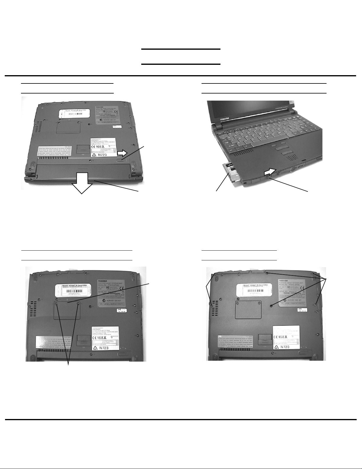
BATTERY PACK REMOVAL OPTIONAL PCMCIA CARD REMOVAL
Release lever
Battery Pack
1. Turn the computer upside down as shown.
2. Slide the battery release lever in the direction of the
arrow and slide the battery out of the computer.
EXPANSION MEMORY REMOVAL PALMREST REMOVAL
Memory
cover
PC card
1. Slide the eject button to the right.
2. Grasp the PC card and remove it.
NOTE: Before removing any PCMCIA device, make sure
it is “Stopped” in the PC Card Manager.
M2x10
black
screws
Eject button
M2x6
black
screws
M2x4 flat head black screws
1. Turn the computer upside down.
2. Remove two M2x4 flat head black screws securing
the memory cover.
3. Lift off the memory cover.
4. Push the memory clips outward and pull the memory
module out of the connector on a 45 degree angle.
TOSHIBA
Tough Enough for Today’s World.
1. Turn the computer upside down.
2. Remove the following screws:
- Two M2x10 black screws
- Four M2x6 black screws
Page 3

FIELD REPLACEABLE UNIT DOCUMENTATION
TM
Portege
3400 Series
PALMREST REMOVAL
Palm rest
cover
Membrane
switch cable
PJ320
3. Turn the computer right side up and lift up the
palm rest cover.
4. Disconnect the membrane switch cable from PJ320
and remove the palm rest cover.
KEYBOARD REMOVAL
MEMBRANE SWITCH REMOVAL
Bracket
Speaker ground plate
1. Remove three M2x3 flat head silver screws
securing the bracket
2. Lift off the bracket and speaker ground plate.
3. Lift off the membrane switch.
M2x3 flat head
silver screws
SPEAKER REMOVAL
Membrane
switch
PJ110
1. Disconnect the keyboard cable from PJ110.
2. Disconnect the accupoint cable from PJ310.
3. Lift out the keyboard.
TOSHIBA
Keyboard
AccuPoint
cable
PJ310
Keyboard
cable
PJ420
1. Disconnect the speaker cable from PJ420 on the
system board.
2. Lift out the speaker assembly and remove the speaker
from the speaker holder.
Speaker
Speaker holder
Tough Enough for Today’s World.
Page 4

FIELD REPLACEABLE UNIT DOCUMENTATION
TM
Portege
3400 Series
DISPLAY ASSEMBLY and UPPER COVER REMOVAL
M2x6 black screws
1. Turn the computer upside down as shown.
2. Remove the following screws.
- Three M2x8 black screws
- Two M2x6 black screws
LED BOARD REMOVAL
PJ300
Insulator
M2x8 black
screws
M2x6 brass screws
3. Turn the computer right side up and disconnect the
LCD harness from PJ300.
4. Remove three M2x6 brass screws securing the
display assembly and lift out the display assembly.
I/O BOARD REMOVAL
Display assembly
LCD
harness
Make sure the
insulator is tuck
in under the top
cover assy
System
board
PJ440
Flexible
cable
LED board
PJ720
1. Remove the LED board lens.
2. Lift out the LED board and disconnect the flexible cable
from PJ720 on the LED board and PJ440 on the
system board.
LED board lens
PJ410
FR board
PJ703
PJ700
I/O board
Glass tape
1. Peel off the glass tape securing the microphone
harness on the I/O board and FR board.
2. Disconnect the microphone cable from PJ703 and lift
out the microphone assembly.
3. Remove glass tape and one M2x4 black screws
securing FR board. Disconnect the FR board from
PJ410 on the system board and from PJ700 on the
I/O board and lift out the FR board.
4. Remove the I/O board from the base assembly.
Microphone assy
TOSHIBA
Tough Enough for Today’s World.
Page 5

FIELD REPLACEABLE UNIT DOCUMENTATION
TM
Portege
3400 Series
HDD REMOVAL
HDD insulator
1. Slide the HDD to the right to disconnect from the
system board.
3. Slide the drive out of the HDD insulator.
SYSTEM BOARD REMOVAL
SYSTEM BOARD REMOVAL
M2x10
black
screws
HDD
1. Turn the computer upside down.
2. Remove four M2x10 black screws securing the
PC-Card assembly.
3. Turn the computer right side up.
MODEM REMOVAL
M2x6 brass screw
Latch hole assembly
4. Remove two M2x6 brass screws and two M2x4 brass
screws securing the system board.
5. Remove one M2x6 brass screw securing the latch
hole assembly and remove the latch hole assembly.
6. Peel off the glass tape securing the RTC battery harness
and disconnect the RTC battery harness from PJ735.
7. Lift out the system board.
M2x6 brass screw
M2x4
brass
screws
System
board
Tape
PJ735
RTC battery
harness
Modem
board
System board assembly
1. Turn the system board assembly upside down.
2. Disconnect the modem board from the system board.
TOSHIBA
Tough Enough for Today’s World.
Page 6

FIELD REPLACEABLE UNIT DOCUMENTATION
TM
Portege
3400 Series
DISPLAY MASK REMOVAL
Latch
LCD cushions
LCD module
Display mask
LCD mask seals
1. Remove two LCD cushions and two LCD mask seals
using a pair of fine-tipped tweezers.
2. Remove four M2.5x4 flat head brass screws securing
the display mask.
3. There are 13 latches securing the display mask.
Carefully insert your fingers between the display mask
and the LCD module and pry open the display mask.
FL INVERTER AND LCD REMOVAL
M2x4
Flat head
brass
screws
LCD module
1. Lift up the FL inverter board and disconnect the FL
cable from CN2 and the FL inverter cable from CN1.
3. Remove three M2x4 flat head brass screws securing
the LCD module.
4. Carefully rotate the LCD module from left to right of
the LCD cover and disconnect the LCD cable from
the LCD module.
LCD cable
FL
cable
FL
inverter
Fl inverter cable
TOSHIBA
Tough Enough for Today’s World.
 Loading...