

Page 1

1
Toshiba Personal Computer
Portege 2000
Maintenance Manual
TOSHIBA CORPORATION
File Number 960-333
Page 2

Copyright
© 2002 by Toshiba Corporation. All rights reserved. Under the copyright laws, this manual cannot be
reproduced in any form without the prior written permission of Toshiba. No patent liability is assumed with
respect to the use of the information contained herein.
Toshiba Portege 2000 Maintenance Manual
First edition January 2002
Disclaimer
The information presented in this manual has been reviewed and validated for accuracy. The included set of
instructions and descriptions are accurate for the Portege 2000series at the time of this manual's production.
However, succeeding computers and manuals are subject to change without notice. Therefore, Toshiba assumes
no liability for damages incurred directly or indirectly from errors, omissions, or discrepancies between any
succeeding product and this manual.
Trademarks
IBM is a registered trademark, and IBM PC/AT, PS/2, OS/2 and VGA are registered trademarks of IBM
Corporation.
Microsoft and MS-DOS and Windows are registered trademarks of Microsoft Corporation.
Intel and Cerelon are registered trademarks, and MMX is a trademark of Intel Corporation.
Sound Blaster and Pro are registered trademarks of Creative Technology Ltd.
Super I/O and MICROWIRE are registered trademarks of National Semicon d ucto r Cor po rati o n.
All other properties are trademarks or registered trademarks of their respective holders.
ii Portege 2000 Maintenance Manual (960-3 33)
Page 3
Preface
This maintenance manual describes how to perform hardware service maintenance for the
Toshiba Personal Computer Portege 2000, referred to as Portege 2000 in this manual.
The procedures described in this manual are intended to help service technicians isolate
faulty Field Replaceable Units (FRUs) and replace them in the field.
SAFETY PRECAUTIONS
Four types of messages are used in this manual to bring important information to your
attention. Each of these messages will be italicized and identified as shown below.
DANGER: “Danger” indicates the existence of a hazard that could result in death or
serious bodily injury, if the safety instruction is not observed.
WARNING: “Warning” indicates the existence of a hazard that could result in bodily
injury, if the safety instruction is not observed.
CAUTION: “Caution” indicates the existence of a hazard that could result in property
damage, if the safety instruction is not observed.
NOTE: “Note” contains general information that relates to your safe maintenance
service.
Improper repair of the computer may result in safety hazards. Toshiba requires service
technicians and authorized dealers or service providers to ensure the following safety
precautions are adhered to strictly.
Be sure to fasten screws securely with the right screwdriver. Be sure to use the PH
Point size “0” and “1” screwdrivers complying with the ISO/DIS 8764-1:1996. If a
screw is not fully fastened, it could come loose, creating a danger of a short circuit,
which could cause overheating, smoke or fire.
If you replace the battery pack or RTC battery, be sure to use only the same model
battery or an equivalent battery recommended by Toshiba. Installation of the wrong
battery can cause the battery to explode.
Portege 2000 Maintenance Manual (960-333) iii
Page 4

The manual is divided into the following parts:
Chapter 1 Hardware Overview describes the Portege 2000 system unit and each
FRU.
Chapter 2 Troubleshooting Procedures explains how to diagnose and resolve
FRU problems.
Chapter 3 Test and Diagnostics describes how to perform test and diagnostic
operations for maintenance service.
Chapter 4 Replacement Procedures describes the removal and replacement of the
FRUs.
Appendices The appendices describe the following:
❑ Handling the LCD module
❑ Board layout
❑ Pin assignment
❑ Keyboard scan/character codes
❑ Key layout
❑ Wiring diagrams
❑ BIOS/KBC/EC Update
❑ Reliability
❑ Key FD
iv Portege 2000 Maintenance Manual (960-3 33)
Page 5

Conventions
This manual uses the following formats to describe, identify, and highlight terms and
operating procedures.
Acronyms
On the first appearance and whenever necessary for clarification acronyms are enclosed in
parentheses following their definition. For example:
Read Only Memory (ROM)
Keys
Keys are used in the text to describe many operations. The key top symbol as it appears on
the keyboard is printed in boldface type.
Key operation
Some operations require you to simultaneously use two or more keys. We identify such
operations by the key top symbols separated by a plus (+) sign. For example, Ctrl + Pause
(Break) means you must hold down Ctrl and at the same time press Pause (Break). If
three keys are used, hold down the first two and at the same time press the third.
User input
Text that you are instructed to type in is shown in the boldface type below:
DISKCOPY A: B:
The display
Text generated by the Portege 3410CT/3440CT that appears on its display is presented in the
type face below:
Format complete
System transferred
Portege 2000 Maintenance Manual (960-333) v
Page 6

Table of Contents
Chapter 1 Hardware Overview
1.1 Features ......................................................................................................................1-1
1.2 1.8-inch Hard Disk Drive...........................................................................................1-9
1.3 Keyboard..................................................................................................................1-11
1.4 TFT Color Display...................................................................................................1-12
1.5 Power Supply ...........................................................................................................1-14
1.6 Batteries....................................................................................................................1-15
1.7 AC Adapter ..............................................................................................................1-17
Chapter 2 Troubleshooting Procedures
2.1 Troubleshooting .........................................................................................................2-1
2.2 Troubleshooting Flowchart........................................................................................2-2
2.3 Power Supply Troubleshooting..................................................................................2-6
2.4 Main Board Troubleshooting...................................................................................2-15
2.5 USB 3.5” FDD Troubleshooting..............................................................................2-27
2.6 1.8” HDD Troubleshooting......................................................................................2-30
2.7 Keyboard Troubleshooting.......................................................................................2-35
2.8 Display Troubleshooting..........................................................................................2-36
2.9 Touch Pad.................................................................................................................2-38
2.10 Modem .....................................................................................................................2-39
2.11 LAN..........................................................................................................................2-41
2.12 Sound........................................................................................................................2-43
2.13 SD card slot..............................................................................................................2-45
2.14 Wireless LAN Troubleshooting...............................................................................2-46
vi Portege 2000 Maintenance Manual (960-333)
Page 7

Chapter 3 Tests and Diagnostics
3.1 The Diagnostic Test ...................................................................................................3-1
3.2 Executing the Diagnostic Test....................................................................................3-3
3.3 Subtest .......................................................................................................................3-7
3.4 System Test................................................................................................................3-9
3.5 Memory Test............................................................................................................3-11
3.6 Keyboard Test..........................................................................................................3-13
3.7 Display Test..............................................................................................................3-16
3.8 USB Floppy Disk Test .............................................................................................3-19
3.9 ASYNC Test ............................................................................................................3-21
3.10 Hard Disk Test .........................................................................................................3-22
3.11 Real Timer Test........................................................................................................3-25
3.12 NDP Test..................................................................................................................3-27
3.13 Expansion Test.........................................................................................................3-28
3.14 Wireless LAN Test Program....................................................................................3-30
3.15 Sound/LAN/Modem Test.........................................................................................3-37
3.16 Error Status Code .....................................................................................................3-39
3.17 HDC Status...............................................................................................................3-41
3.18 FDD Cleaning ..........................................................................................................3-43
3.19 Log Utilities..............................................................................................................3-44
3.20 Running Test............................................................................................................3-46
3.21 Floppy Disk Drive Utilities......................................................................................3-48
3.22 System Configuration...............................................................................................3-54
Chapter 4 Replacement Procedures
4.1 Overview....................................................................................................................4-1
4.2 Battery pack/PC card..................................................................................................4-8
4.3 Memory Module.......................................................................................................4-11
4.4 HDD .........................................................................................................................4-14
4.5 Keyboard/Bottom cover...........................................................................................4-17
4.6 Speaker/RTC battery................................................................................................4-22
Portege 2000 Maintenance Manual (960-3 33) vii
Page 8

4.7 Wireless LAN board/MDC board/HDD cable.........................................................4-24
4.8 PC card slot ..............................................................................................................4-27
4.9 Main board/FAN .....................................................................................................4-28
4.10 Sound board/SW knob .............................................................................................4-31
4.11 Touch pad/MODEM jack/LED SW membrane.......................................................4-33
4.12 Power Membrane SW/Wireless LAN antenna.........................................................4-37
4.13 LCD mask/FL inverter/LCD/LCD cable..................................................................4-41
4.14 Hinge........................................................................................................................4-47
4.15 Fluorescent Lamp.....................................................................................................4-51
Appendices
Appendix A Handling the LCD Module.........................................................................A-1
Appendix B Board Layout..............................................................................................B-1
Appendix C Pin Assignment .......................................................................................... C-1
Appendix D Keyboard Scan/Character Codes................................................................D-1
Appendix E Key Layout................................................................................................. E-1
Appendix F BIOS/KBC/EC Update................................................................................F-1
Appendix G Reliability...................................................................................................G-1
Appendix H Key FD.......................................................................................................H-1
viii Portege 2000 Maintenance Manual (960-3 33)
Page 9

Chapter 1
Hardware Overview
Page 10

1 Hardware Overview
1 Hardware Overview
1-ii Portege 2000 Maintenance Manual (960- 3 33)
Page 11

1 Hardware Overview
Chapter 1 Contents
1.1 Features ......................................................................................................................1-1
1.2 1.8-inch Hard Disk Drive...........................................................................................1-9
1.3 Keyboard..................................................................................................................1-11
1.4 TFT Color Display...................................................................................................1-12
1.4.1 LCD Module.......................................................................................1-12
1.4.2 FL Inverter Board...............................................................................1-13
1.5 Power Supply ...........................................................................................................1-14
1.6 Batteries....................................................................................................................1-15
1.6.1 Main Battery.......................................................................................1-15
1.6.2 Battery Charging Control ...................................................................1-16
1.6.3 RTC battery ........................................................................................1-16
1.7 AC Adapter ..............................................................................................................1-17
Portege 2000 Maintenance Manual (960-333) 1-iii
Page 12

1 Hardware Overview
Figures
Figure 1-1 Front of the computer.....................................................................................1-4
Figure 1-2 System units configuration.............................................................................1-4
Figure 1-3 System Block Diagram...................................................................................1-5
Figure 1-4 1.8-inch HDD.................................................................................................1-9
Tables
Table 1-1 1.8-inch HDD dimensions..............................................................................1-9
Table 1-2 1.8-inch HDD Specifications .......................................................................1-10
Table 1-3 LCD module specifications..........................................................................1-12
Table 1-4 FL inverter board specifications...................................................................1-13
Table 1-5 Power supply output specifications..............................................................1-14
Table 1-6 Battery specifications...................................................................................1-15
Table 1-7 Time required for charges of main battery...................................................1-16
Table 1-8 RTC battery charging/data preservation time ..............................................1-16
Table 1-9 AC adapter specifications.............................................................................1-17
1-iv Portege 2000 Maintenance Manual (960- 3 33)
Page 13

1.1 Features 1 Hardware Overview
1 Features
1.1 Features
The Portage 2000 is a ultra thin and lightweight PC realizing cable-less environment on a
table by wireless function with a Pentium III processor realizing high performance.
❑ Microprocessor
Pentium III-ULV
A 750/350MHz Pentium III-ULV processor with a 750/350MHz internal clock,
100MHz bus and 1.10/0.95V core operation.
❑ Cache memory
A Pentium III has 32KB primary cache and 512KB secondary cache (in CPU)
❑ Memory
One memory slot. Memory module can be installed to provide a maximum of 512MB.
Memory modules in 256MB size is available.
❑ VRAM
16MB VRAM in ALi/Trident NAPA2T.
❑ HDD
Single 20GB internal drive. 1.8-inch, 8.0mm height
❑ USB FDD
Three-mode 3.5 inch USB FDD supporting 720KB, 1.2MB and 1.44MB formats is
prepared as option.
❑ Display
LCD
Built-in 12.1 inch, 262,144 colors, XGA (1024×768 dots), thin type low temperature
poly- silicon TFT color display. Video controller is included in North Bridge chip.
CRT
Supported via an RGB connector
Portege 2000 Maintenance Manual (960-333) 1-1
Page 14

1 Hardware Overview 1.1 Features
❑ Keyboard
Keyboards has 84(US)/85(UK)-key and supports Windows key.
❑ Touch pad
Touch pad is installed as a pointing device.
❑ Battery
The RTC battery is mounted inside computer.
The main battery is a detachable lithium polymer main battery (10.8V-1,600mAh)
and the RTC battery is a lithium ion battery(3V-17mAH).
❑ USB (Universal Serial Bus)
Four USB ports supporting USB 2. Two of these are occupied and others are usable.
❑ PC card slot
A PC card Type I or II is acceptable. Supports ToPIC-100 (3.3V/CardBus).
❑ SD card slot
One SD card slot.
❑ Sound system
Incorporates an internal speaker, external monaural microphone connector and stereo
headphone connector.
❑ One touch button
Internet button and Mail button are installed.
❑ Built-in Modem
The computer contains a MDC, enabling data and fax communication. It supports
ITU-TV.90. The transfer rates are 56 Kbps for data reception, 33.6 Kbps for data
transmission, and 14,400 bps for fax transmission. However, the actual speed
depends on the line quality. The RJ11 modem jack is used to accommodate a
telephone line.
❑ LAN
The internal LAN supports 10BASE-T and 100BASE-TX.
1-2 Portege 2000 Maintenance Manual (960-333)
Page 15

1.1 Features 1 Hardware Overview
❑ Wireless LAN
The internal wireless LAN supports Mini PCI Type III(802.11B) made by Agere.
❑ FIR(Fast Serial InfraRed) communication port
Fast Serial InfraRed(FIR) communication port supports IrDA1.1. 1.15Mbps or
4Mbps wireless communication is realized by this FIR.
Portege 2000 Maintenance Manual (960-333) 1-3
Page 16
1 Hardware Overview 1.1 Features
d
N
k
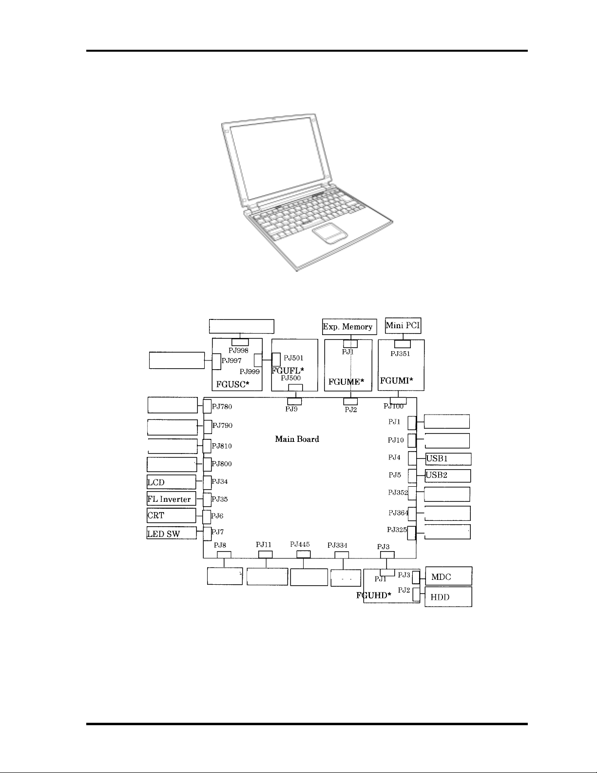
Figure 1-1 shows the front of the computer and Figure 1-2 shows the system units
configuration.
Figure 1-1 Front of the computer
Headphone
Fan
RTC Battery
Battery
AC Adapter
Outer Microphone
Intouch
PC Car
Keyboard
Docking I/F
Speaker
etwor
SD Card
Debug Port
Figure 1-2 System units configuration
1-4 Portege 2000 Maintenance Manual (960-333)
Page 17
1.1 Features 1 Hardware Overview
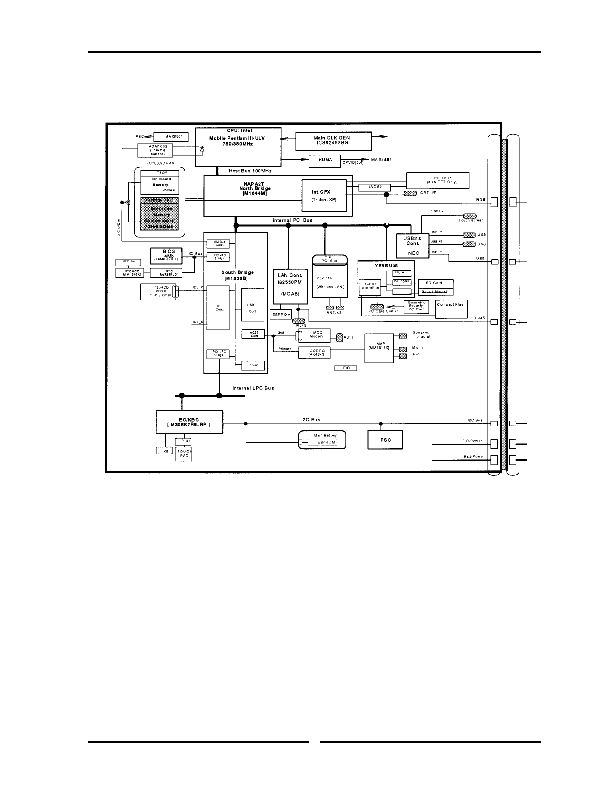
Figure 1-3 shows the system block diagram.
Figure 1-3 System Block Diagram
Portege 2000 Maintenance Manual (960-333) 1-5
Page 18

1 Hardware Overview 1.1 Features
The PC contains the following components.
❑ CPU
Pentium III-ULV
• A 750/350MHz Pentium III processor with a 750/350MHz internal clock,
100MHz bus and 1.10V/0.95 core operation voltage (built-in NDP).
• Internal cache memory: 16KB Data and 16KB Instruction, Write-Back
• Secondary cache memory: 512KB (in CPU)
❑ Memory
One memory slot capable of accepting 256MB-memory module for a maximum of
512MB.
• 3.3V operation
• 140-pin exclusive memory board
• Access time : 6ns
• Memory Supporting PC-133(Operation is PC100)
❑ BIOS ROM (Flash memory)
• 4Mbit (256K×16-bit chip)
− 64KB used for logo
− 64KB used for setup and checksum
− 128KB used for system BIOS
− 64KB used for VGA-BIOS
− 64KB used for ACPI
− 8KB used for PnP
− 8KB used for password security
− 16KB used for booting
− 64KB used for LAN
− 32KB are reserved
• 5.0V operation
• Access time : 120 ns or 90 ns
• Data transfer: 8-bit
1-6 Portege 2000 Maintenance Manual (960-333)
Page 19

1.1 Features 1 Hardware Overview
❑ PCI chipset
This gate array incorporates the following elements and functions
• North Bridge (Ali/Trident-made M1644T)
− Pentium II/III supported
− Maximum capacity of SDRAM or DDR-SDRAM is 3GB
− DRAM control
− Complies with AGP V2.0 x 4 modes
− Complies with PCI R2.2
− Complies with APCI 1.0b
− PCI Mobile Busy#/STOP# supported
− 555-ball 35x35mm BGA package
• South Bridge (Ali/Trident-made M1535B)
− PCI 3.3V/5V tolerance interface
− Provides Steerable PCI interrupts for PCI device Plug-and-Play
− Enhanced DMA controller
− Interrupt controller
− Counter/timers
− Distributed DMA supported
− PC/PCI DMA supported
− Serial IRQ supported
− Low Pin Count (LPC) host controller
− Plug-and-Play supported
− Built-in KB controller
− ACPI supporting features
− Built-in PCI IDE controller
− USB interface
− SMBus interface
− Super I/O interface
− Audio system
− SW modem interface
− 352-ball (27mm x 27mm) BGA package
❑ VGA controller
Included in North Bridge
❑ PC card controller (YEBISU3S)
• PCI interface (PCI Reision2)
• Chipset interface
Intel serial interrupt
• CardBus/PC Card controller (Yenta Version2.2) :2 slots
Portege 2000 Maintenance Manual (960-333) 1-7
Page 20

1 Hardware Overview 1.1 Features
Parallel power supply control (Toshiba style) and serial power supply control
(Texas Instruments style)
• SD card controller (SDHC Ver.1.2)
• SDIO card controller (Ver.1.0)
• SmertMedia controller (SMHC Ver.01/SMIL 1.0)
• SmertCard interface
• SIO controller
• Docking station interface
Q switch control, reset control
• External device interface
FDD/IDE hot plugging and removal control
❑ Other main system chips
• EC/KBC (Mitsubishi-made LPC microcontroller M306K5F8LRP x 1)
• PSC (TMP87PM48U x 1)
• Temperature sensor (ADM1032 x 1)
2
PROM (BR93LC46F-Q (used for LAN MAC address))
• E
❑ Modem controller
Supported by MDC. Using of the secondary AC97 Line
❑ LAN controller (MOAB-made Intel:82550PM)
Controls LAN, supports 100Base-TX and 10Base-T.
1-8 Portege 2000 Maintenance Manual (960-333)
Page 21
1.2 1.8-inch Hard Disk Drive 1 Hardware Overview
1.2 1.8-inch Hard Disk Drive
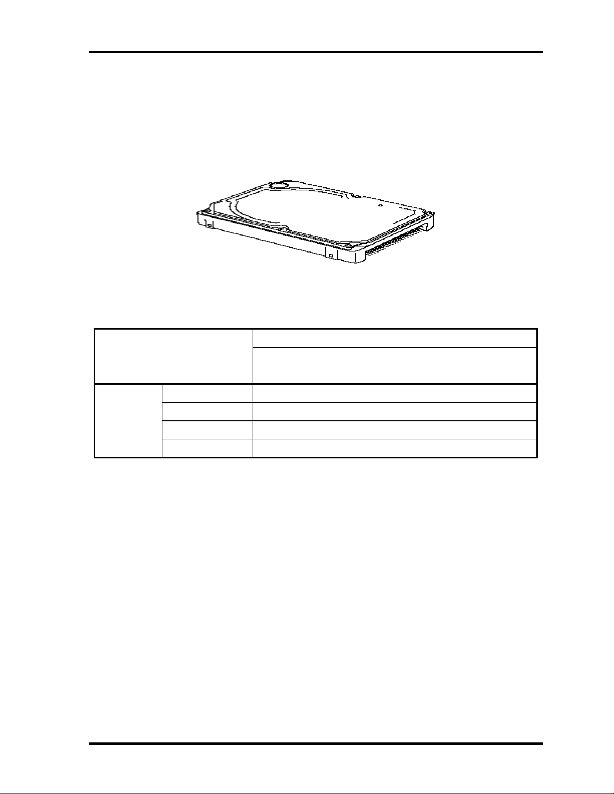
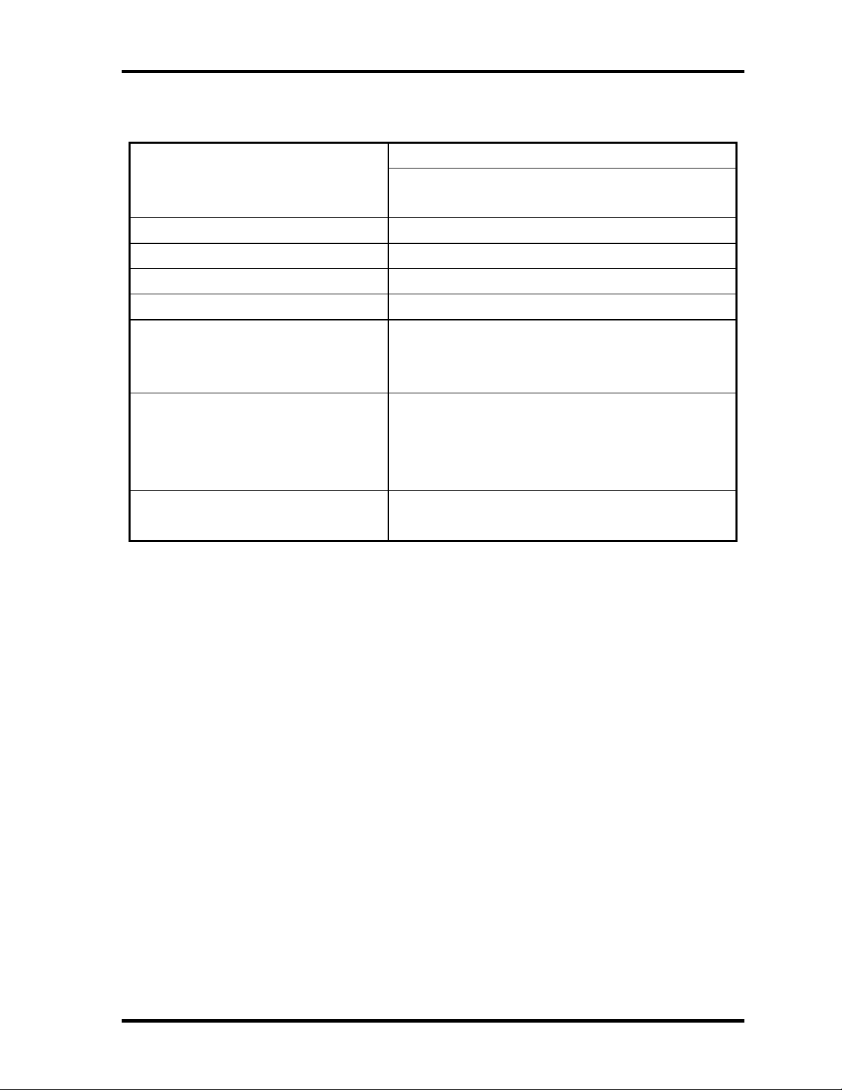
A compact, high-capacity HDD with a height of 8.0mm. Contains a 1.8-inch magnetic disk
and magnetic heads.
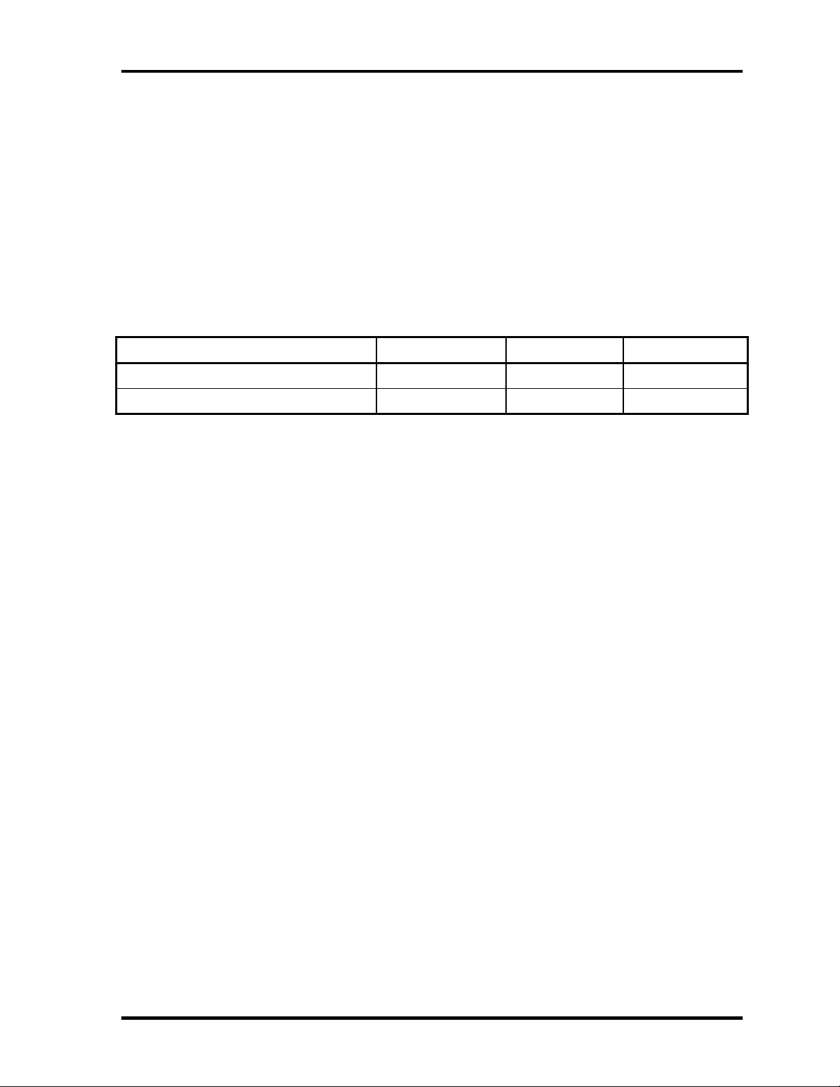
Figure 1-4 shows a view of the 1.8-inch HDD and Tables 1-1 and 1-2 list the specifications.
Figure 1-4 1.8-inch HDD
Table 1-1 1.8-inch HDD dimensions
Standard value
Parameter
Outline Width (mm) 54.0
dimensions Height (mm) 8.0
Depth (mm) 78.5
Weight (g) 62 (MAX)
TOSHIBA
MK2003GAH
Portege 2000 Maintenance Manual (960-333) 1-9
Page 22
1 Hardware Overview 1.2 1.8-inch Hard Disk Drive
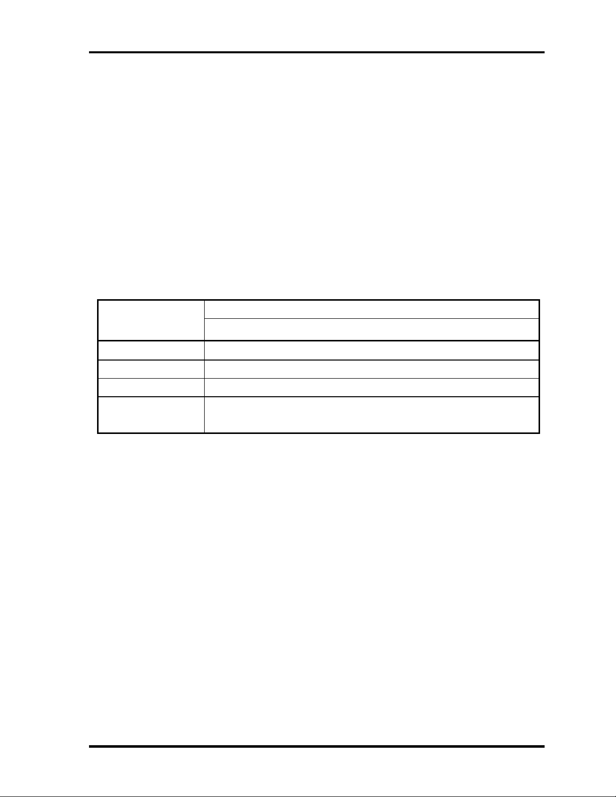
Table 1-2 1.8-inch HDD Specifications
Specification
Parameter
Storage size (formatted) 20GB
Speed (RPM) 4,200
Data transfer speed (Mbits/s) 115.6 to 204.4
Interface transfer rate (MB/s) 100
Track density
Track/mm(TPI)
Bit/mm
Access time (msec)
Track to track
Average time
Max seek
Start time (sec) 3.5 (Typ.)
TOSHIBA
MK2003GAH
2237 (56.8K) max.
24.4K(621K) max.
3
15
26
20 (Max.)
1-10 Portege 2000 Maintenance Manual (960-333)
Page 23

1.3 Keyboard 1 Hardware Overview
1.3 Keyboard
The keyboard is mounted 84(US)/85(UK) keys that consist of character key and control key,
and in conformity with JIS. The keyboard is connected to membrane connector on the system
board and controlled by the keyboard controller. See Appendix E about a layout of the
keyboard.
Portege 2000 Maintenance Manual (960-333) 1-11
Page 24
1 Hardware Overview 1.4 TFT Color Display
1.4 TFT Color Display
The TFT color display consists of a LCD module and FL inverter board.
1.4.1 LCD Module
The LCD module used for the TFT color display uses a backlight as the light source and can
display images and characters of 262,144 colors with 1024×768 resolution. The video
controller is incorporated into the North Bridge (M1644M) chip and can control both internal
and external XGA-support displays simultaneously.
Table 1-5 shows list the specifications.
Table 1-3 LCD module specifications (12.1 TFT)
Specifications Item
VF2095P01
Number of Dots
Dot spacing (mm) 0.24(H) x 0.24(V)
Display range (mm) 245.76(H) x 184.32(V)
Outline
dimensions
267.4(w) x 197.5(H) x 5.55Max(D)
1024×768
1-12 Portege 2000 Maintenance Manual (960-333)
Page 25
1.4 TFT Color Display 1 Hardware Overview
1.4.2 FL Inverter Board
The FL inverter board supplies a high frequency current to illuminate the LCD module FL.
Table 1-4 lists the FL inverter board specifications.
Table 1-4 FL inverter board specifications
Specifications Item
UA2040P02
Input Voltage (V) DC 5
Output
Voltage (V) 750
Current MAX (mA) 4.22
Current MIN (mA) 0.412
Portege 2000 Maintenance Manual (960-333) 1-13
Page 26
1 Hardware Overview 1.5 Power Supply
1.5 Power Supply
The power supply supplies ten different voltages to the system board.
The power supply microcontroller has the following functions.
1. Judges that the DC power supply (AC adapter) is connected to the computer.
2. Detects DC output and circuit malfunctions.
3. Controls the battery icon, and DC IN icon.
4. Turns the battery charging system on and off and detects a fully charged battery.
5. Turns the power supply on and off.
6. Provides more accurate detection of a low battery.
7. Calculates the remaining battery capacity.
8. Controls the transmission of the status signal of the main battery.
Table 1-5 lists the power supply output specifications.
Table 1-5 Power supply output specifications
Name
PCOREV
PGTLV
B1R8V 1.8
B3V
B2R5V
P3V
B5V
VCC
Voltage
[V]
1.35±0.1V
1.50±3%
3.30±5%
2.5±5%
3.30±5%
5.00±5%
5.00±5%
Name/Use
PⅢ-ULV
PⅢ-ULV , M1644
M1644
M1644,CLKGen(ICS94258), Memory slot1/2, YEBISUSS, PCMCIA
slot1, MDC(Asky), LAN(REL8139CL)
M1644M, CLKGen(ICS94258)
CPU(ADM11032), M1535, LCD, BIOS(TC58F401FT),
RTC(bq3285LD), Sound(YMF753),Mini PCI(Wireless LAN)
M1644, PCMCIA slot1
M1535, FLINV, YEBISUSS, Sound(YMF753), HDD, CD-R/W, USB,
FAN
SNDVCC
S5V
5.00±5%
5.00±5%
Sound(MMM1517)
CPU(MAX6501), SB(M1535)
1-14 Portege 2000 Maintenance Manual (960-333)
Page 27
1.6 Batteries 1 Hardware Overview
1.6 Batteries
The PC has the following two batteries.
❑ Main battery
❑ Real time clock (RTC) battery
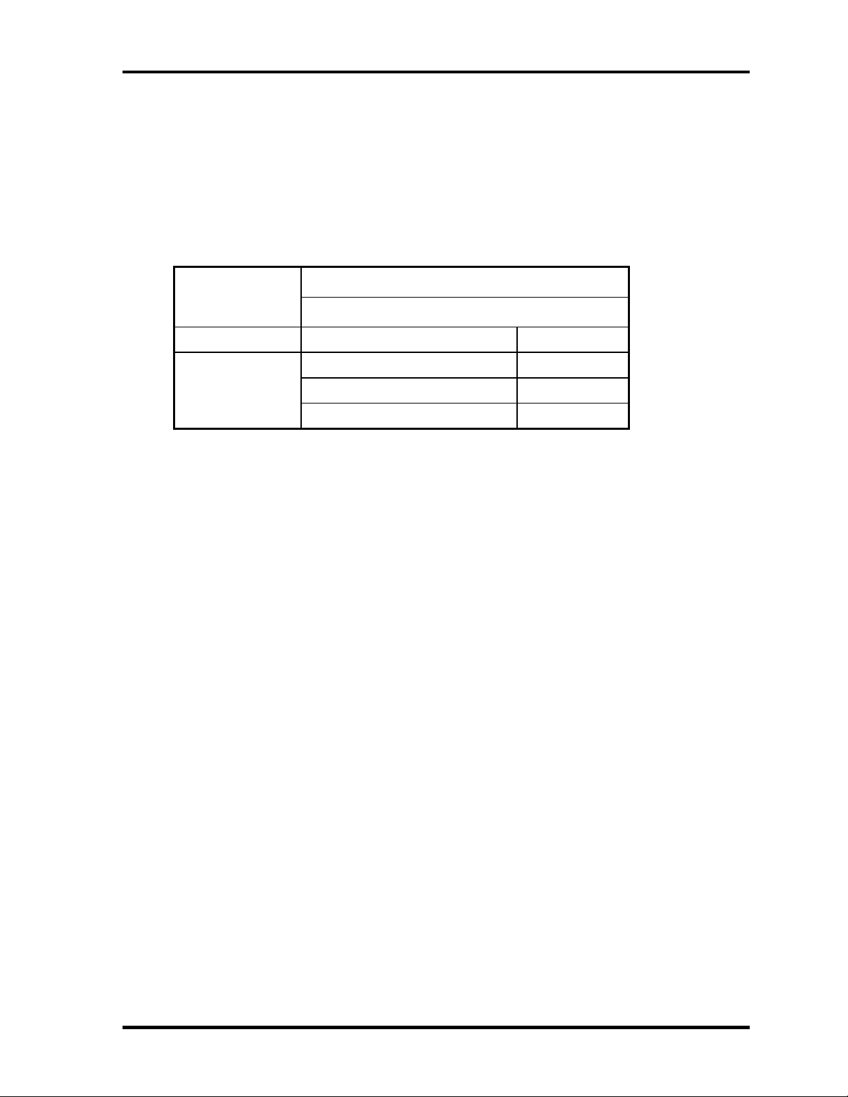
Table 1-6 lists the specifications for these two batteries.
Table 1-6 Battery specifications
Battery Name Battery Element Output Voltage Capacity
Main battery (XM2043P02) Lithium ion 10.8V 1600mAh
Real time clock (RTC) battery Nickel hydride 3.0 V 17 mAh
1.6.1 Main Battery
The main battery is the primary power supply for the computer when the AC adapter is not
connected. In resume (instant recovery) mode, the main battery maintains the current status
of the computer.
Portege 2000 Maintenance Manual (960-333) 1-15
Page 28
1 Hardware Overview 1.6 Batteries
Q
A
1.6.2 Battery Charging Control
Battery charging is controlled by a power supply microprocessor. The power supply
microprocessor controls power supply and detects a full charge when the AC adaptor and
battery are connected to the computer. The system charges the battery using quick charge or
trickle charge.
❑ Quick Battery Charge
When the AC adapter is connected, normal charging is used while the system is
turned on and quick charge is used while the system is turned off or in suspend mode.
(See Table 1-7)
Table 1-7 Time required for charges of main battery
uick charge
bout 2 hours
Quick battery charge is stopped in the following cases.
1. The main battery is fully charged
2. The main battery is removed
3. Main battery or AC adapter voltage is abnormal
4. Charging current is abnormal
❑ Trickle charge
When the main battery is fully charged and the AC adapter is plugged in, the power
supply microcontroller automatically switches from quick charge to trickle charge.
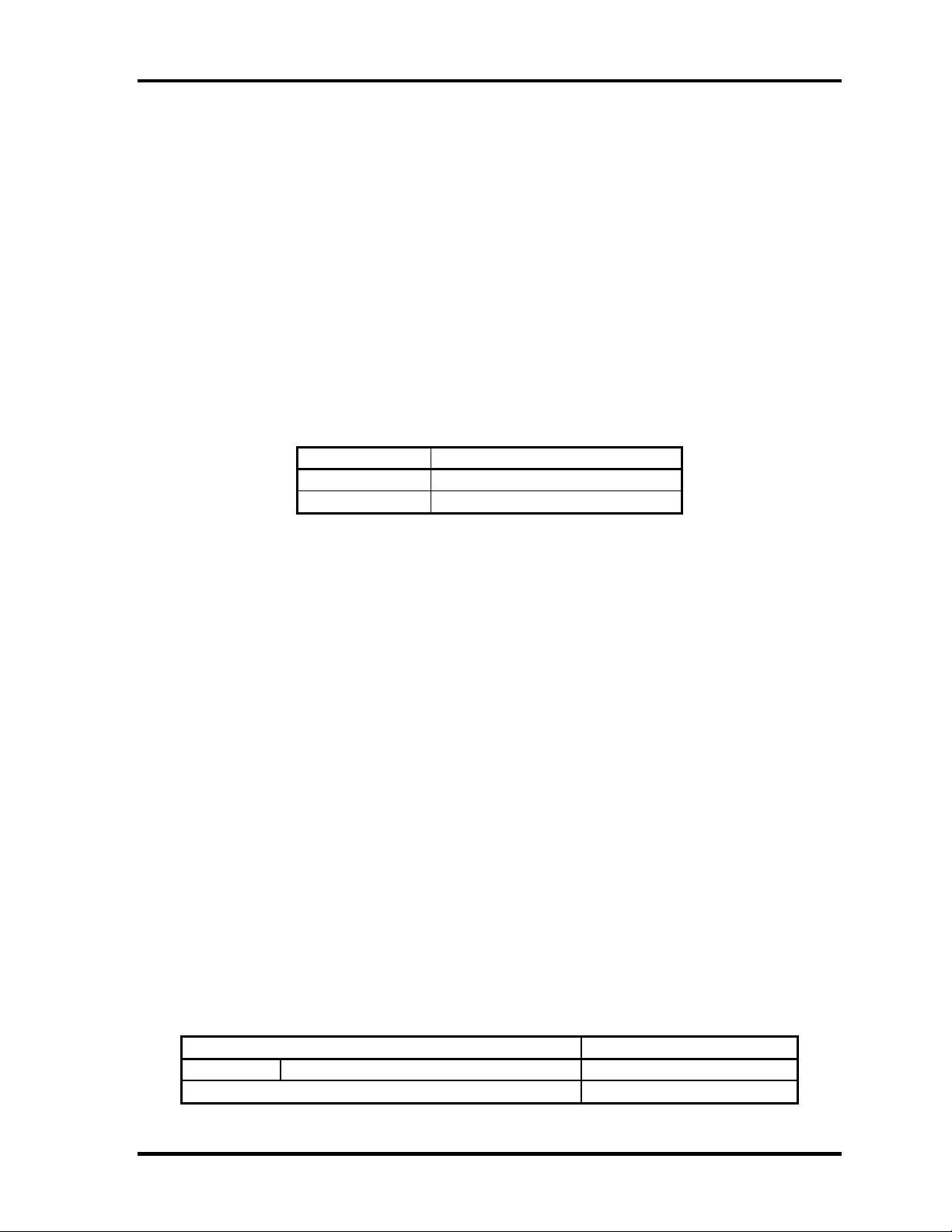
1.6.3 RTC Battery
The RTC battery provides the power supply to maintain the date, time, and other system
information in memory. Table 1-8 lists the battery charging time and data preservation times.
Table 1-8 RTC battery charging/data preservation time
Data preservation time (when fully charged) 1 month
1-16 Portege 2000 Maintenance Manual (960-333)
Page 29
1.7 AC Adapter 1 Hardware Overview
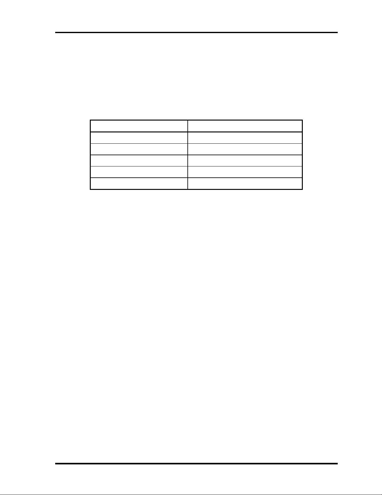
1.7 AC Adapter
The AC adapter is also used to charge the battery.
Table 1-9 lists the AC adapter specifications.
Table 1-9 AC adapter specifications
Parameter Specification
Input voltage AC 90 to 264V
Input frequency 47Hz/63Hz
Input current(MAX) 1.2A (100VAC)
Output voltage DC 15V
Output current 3.0A
Portege 2000 Maintenance Manual (960-333) 1-17
Page 30

1 Hardware Overview 1.7 AC Adapter
1-18 Portege 2000 Maintenance Manual (960-333)
Page 31

Chapter 2
Troubleshooting Procedures
Page 32

2 Troubleshooting Procedures
2
2-ii Portege 2000 Maintenance Manual (960-333)
Page 33

2 Troubleshooting Procedures
Chapter 2 Contents
2.1 Troubleshooting .........................................................................................................2-1
2.2 Troubleshooting Flowchart........................................................................................2-2
2.3 Power Supply Troubleshooting..................................................................................2-6
Procedure 1 Power Status Check................................................................2-7
Procedure 2 Error Code Check...................................................................2-9
Procedure 3 Connection Check ................................................................2-13
Procedure 4 Quick Charge Check ............................................................2-13
Procedure 5 Replacement Check..............................................................2-14
2.4 Main Board Troubleshooting...................................................................................2-15
Procedure 1 Message Check.....................................................................2-16
Procedure 2 Debug Port Check on Boot Mode........................................2-18
Procedure 3 Diagnostic Test Program Execution Check .........................2-26
Procedure 4 Replacement Check..............................................................2-26
2.5 USB 3.5” FDD Troubleshooting..............................................................................2-27
Procedure 1 FDD Head Cleaning Check..................................................2-27
Procedure 2 Diagnostic Test Program Execution Check .........................2-28
Procedure 3 Connector Check and Replacement Check..........................2-29
2.6 1.8” HDD Troubleshooting......................................................................................2-30
Procedure 1 Partition Check.....................................................................2-30
Procedure 2 Message Check.....................................................................2-31
Procedure 3 Format Check.......................................................................2-32
Procedure 4 Diagnostic Test Program Execution Check .........................2-33
Procedure 5 Connector Check and Replacement Check..........................2-34
2.7 Keyboard Troubleshooting.......................................................................................2-35
Procedure 1 Diagnostic Test Program Execution Check .........................2-35
Procedure 2 Connector Check and Replacement Check..........................2-35
Portege 2000 Maintenance Manual (960-333) 2-iii
Page 34

2 Troubleshooting Procedures
2.8 Display Troubleshooting..........................................................................................2-36
Procedure 1 Diagnostic Test Program Execution Check .........................2-36
Procedure 2 Connector and Cable Check.................................................2-36
Procedure 3 Fuse connection check .........................................................2-36
Procedure 4 Replacement Check..............................................................2-40
2.9 Touch Pad.................................................................................................................2-38
Procedure 1 Diagnostic Test Program Execution Check .........................2-38
Procedure 2 Connector checking and replacement checking...................2-38
Procedure 3 Replacement Check..............................................................2-38
2.10 Modem .....................................................................................................................2-39
Procedure 1 Diagnostic Test Program Execution Check .........................2-39
Procedure 2 Connector checking and replacement checking...................2-40
2.11 LAN..........................................................................................................................2-41
Procedure 1 Diagnostic Test Program Execution Check .........................2-41
Procedure 2 Connector checking and replacement checking...................2-42
2.12 Sound........................................................................................................................2-43
Procedure 1 Diagnostic Test Program Execution Check .........................2-43
Procedure 2 Connector Check..................................................................2-42
Procedure 3 Replacement Check..............................................................2-44
2.13 SD card slot..............................................................................................................2-45
Procedure 1 Check on Windows ..............................................................2-54
Procedure 2 Connector/ Replacement Check...........................................2-45
2.14 Wireless LAN Troubleshooting...............................................................................2-46
Procedure 1 Trancemitting-Receiving Check ..........................................2-46
Procedure 2 Antennas’ Connection Check...............................................2-47
Procedure 3 Antenna Check.....................................................................2-48
Procedure 4 Replacement Check..............................................................2-50
2-iv Portege 2000 Maintenance Manual (960-333)
Page 35

2 Troubleshooting Procedures
Figures
Figure 2-1 Troubleshooting flowchart(1/2) .....................................................................2-3
Figure 2-2 Troubleshooting flowchart(2/2) .....................................................................2-4
Figure 2-3 A set of tool for debug port test....................................................................2-18
Figure 2-4 Antenna Test jig ...........................................................................................2-48
Tables
Table 2-1 Battery icon....................................................................................................2-7
Table 2-2 DC IN icon.....................................................................................................2-7
Table 2-3 D port status .................................................................................................2-20
Table 2-4 FDD error code and status............................................................................2-28
Table 2-5 Hard disk drive error code and status...........................................................2-33
Portege 2000 Maintenance Manual (960-333) 2-v
Page 36

2 Troubleshooting Procedures
2-vi Portege 2000 Maintenance Manual (960-333)
Page 37

2.1 Troubleshooting 2 Troubleshooting
2
2.1 Troubleshooting
Chapter 2 describes how to determine which Field Replaceable Unit (FRU) in the computer is
causing the computer to malfunction. (The “FRU” means the replaceable unit in the field.)
The FRUs covered are:
1. Power supply 7. Touch pad
2. Main Board 8. Modem
3. 3.5" USB FDD 9. LAN
4. 1.8" HDD 10. Sound
5. Keyboard 11. SD card slot
6. Display 12. Wireless LAN
The Detailed replacement procedures are given in Chapter 4. Test Program operations are
described in Chapter 3.
The following tools are necessary for implementing the Diagnostics procedures:
1. Diagnostics Disk (Test program for maintenance)
2. Phillips screwdrivers
NOTE: Be sure to use the PH point size “0” screwdriver complying with the ISO/DIS
8764-1:1996.
3. Toshiba MS-DOS system FD
4. Work disk (for FDD testing)
5. Cleaning disk kit (for FDD head cleaning)
6. A set of tools for debug port test (test cable, test board, RS-232C cross cable, display,
D port FD)
7. PC with a serial port (for displaying debug port test result)
8. Wraparound connector for PC card
9. Tester
10. External CRT
11. External USB Keyboard
12. External USB mouse
13. Headphone
14. Microphone
15. RJ-11 connector checker LED
16. LAN wraparound connector
17. Speaker with S/PDIF input terminal
Portege 2000 Maintenance Manual (960-333) 2-1
Page 38

2 Troubleshooting Procedures 2.2 Troubleshooting Flowchart
2.2 Troubleshooting Flowchart
Use the flowchart in Figure 2-1 as a guide for determining which FRU malfunctions. Before
going through the flowchart steps, check the following:
®
Make sure that Toshiba Windows
Toshiba operating systems can cause the computer malfunction.
Make sure all optional equipment is removed from the computer.
Make sure the USB FDD is empty.
98,2000 or XP is installed on the hard disk. Non-
2-2 Portege 2000 Maintenance Manual (960-333)
Page 39

2.2 Troubleshooting Flowchart 2 Troubleshooting
START
Connect the AC adapter
to the DC IN socket.
Does the DC IN icon glow?
Yes
Does the Battery icon glow?
Perform the Power Supply
No
Troubleshooting Procedures
in section 2.3.
Perform the Power Supply
No
Troubleshooting Procedures
in section 2.3.
Yes
Turn the Power Switch on.
Perform the Power Supply
Does the DC IN icon flash when the
power is turned on?
No
Is an error message displayed?
Yes
Troubleshooting Procedures
in section 2.3.
Perform the Main Board
Yes
Troubleshooting Procedures
in section 2.4.
Is the
Yes
No
Perform the Display
No
Troubleshooting Procedures
in section 2.8.
“Toshiba” logo
message displayed?
If the “Password=” message displays,
type the password.
Perform the 1.8” HDD
Are Toshiba Windows 98,2000 or
XP being loaded?
No
Troubleshooting Procedures
in section 2.6.
Yes
1
Figure 2-1 Troubleshooting flowchart (1/2)
Portege 2000 Maintenance Manual (960-333) 2-3
Page 40

2 Troubleshooting Procedures 2.2 Troubleshooting Flowchart
A
Do typed characters
appear correctly?
Insert the diagnostic disk into USB FDD
and run the diagnostics test program.
(The reboot of the PC is needed.)
1
Yes
Perform the Keyboard
No
Troubleshooting Procedures
in section 2.7.
Do the touch pad work
correctly?
Yes
Insert the diagnostic disk into USB FDD
and run the diagnostics test program.
(The reboot of the PC is needed.)
Perform the Touch pad
No
Troubleshooting Procedures
in section 2.9.
Perform the 3.5” USB FDD
No
Is the diagnostic test loaded?
Troubleshooting Procedures
in section 2.5.
Yes
Perform each test of the diagnostic test.
Is an error
detected by any of the
diagnostic test?
No
Yes
fter conforming which diagnostic
test has detected an error, perform
the appropriate procedures as
outlined below.
System is normal.
END
Figure 2-2 Troubleshooting flowchart (2/2)
2-4 Portege 2000 Maintenance Manual (960-333)
Page 41

2.2 Troubleshooting Flowchart 2 Troubleshooting
If the diagnostics program cannot detect an error, the problem may be intermittent. The Test
program should be executed several times to isolate the problem. Check the Log Utilities
function to confirm which diagnostic test detected an error(s), then perform the appropriate
troubleshooting procedures as follows:
1. If an error is detected on the system test, memory test, display test, Expansion test,
Real timer test or Sound/LAN/modem test, perform the Main Board Troubleshooting
Procedures in Section 2.4.
2. If an error is detected on the floppy disk test, perform the USB FDD Troubleshooting
Procedures in Section 2.5.
3. If an error is detected on the hard disk test, perform the HDD Troubleshooting
Procedures in Section 2.6.
4. If an error is detected on the keyboard test, perform the Keyboard Troubleshooting
Procedures in Section 2.7.
5. If an error is detected on the display test, perform the Display Troubleshooting
Procedures in Section 2.8.
Portege 2000 Maintenance Manual (960-333) 2-5
Page 42

2 Troubleshooting Procedures 2.3 Power Supply Troubleshooting
2.3 Power Supply Troubleshooting
The power supply controller controls many functions and components. To determine if the
power supply is functioning properly, start with Procedure 1 and continue with the other
Procedures as instructed. The procedures described in this section are:
Procedure 1: Power supply icon Check
Procedure 2: Error Code Check
Procedure 3: Connection Check
Procedure 4: Quick Charge Check
Procedure 5: Replacement Check
2-6 Portege 2000 Maintenance Manual (960-333)
Page 43

2.3 Power Supply Troubleshooting 2 Troubleshooting
Procedure 1 Power supply icon Check
The following two icons indicate the power supply status:
Battery icon
DC IN icon
The power supply controller uses the power supply status with the Battery icon and the DC IN
icon as listed in the tables below.
Table 2-1 Battery icon
Battery icon Power supply status
Lights orange Battery is charged and the external DC is input. It has no relation with
ON/OFF of the system power.
Lights green Battery is fully charged and the external DC is input. It has no relation
with ON/OFF of the system power.
Blinks orange
(even intervals)
Flashes orange The battery level is low and the power switch is pressed on in the
Doesn’t light Any condition other than those above.
The battery level is low while the system power is ON.
battery driving.
Table 2-2 DC IN icon
DC IN icon Power supply status
Lights green DC power is being supplied from the AC adapter.
Blinks orange
Doesn’t light Any condition other than those above.
Power supply malfunction
* 3
*3 When the power supply controller detects a malfunction, the DC IN icon blinks
orange. It shows an error code.
Portege 2000 Maintenance Manual (960-333) 2-7
Page 44

2 Troubleshooting Procedures 2.3 Power Supply Troubleshooting
When icons are blinking, perform the following procedure.
1. Remove the battery pack and the AC adapter and cut off the power supply to the
computer by force.
2. Re-attach the battery pack and the AC adapter.
If icon s are still blinking after the operation above, check the followings:
Check 1 If the DC IN icon blinks orange, go to Procedure 2.
Check 2 If the DC IN icon does not light, go to Procedure 3.
Check 3 If the battery icon does not light orange or green, go to Procedure 4.
CAUTION: Use a recommended AC adapter (ADP-45W) only.
2-8 Portege 2000 Maintenance Manual (960-333)
Page 45

2.3 Power Supply Troubleshooting 2 Troubleshooting
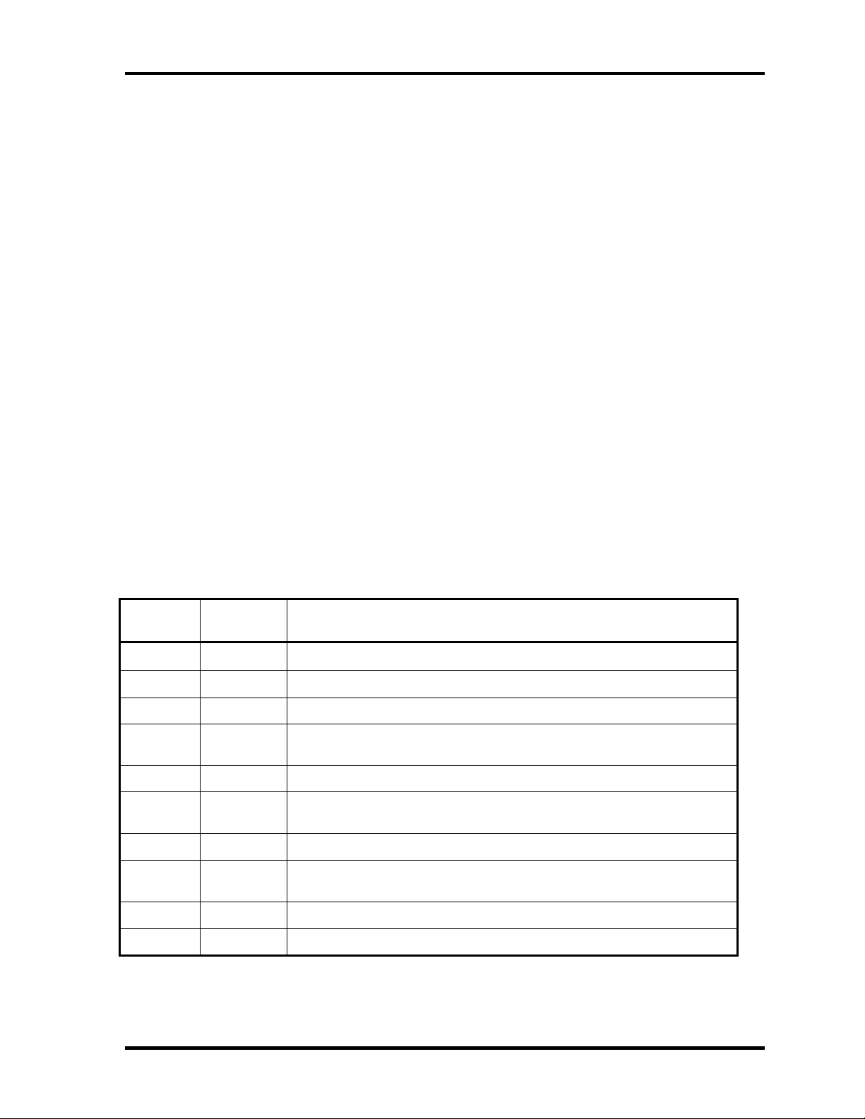
Procedure 2 Error Code Check
If the power supply microprocessor detects a malfunction, the DC IN icon blinks orange. The
blink pattern indicates an error as shown below.
Start Off for 2 seconds
Error code (8 bit)
“1” On for one second
“0” On for half second
Interval between data bits On for half second
The error code begins with LSB (Least Significant bit)
Example: Error code 11h (Error codes are given in hexadecimal format.)
On
Off
Start D0 D1 D2 D3 D4 D5 D6 D7
Re ad
1 0 0 0 1 0 0 0
Order
Check 1 Convert the DC IN icon blink pattern into the hexadecimal error code and
compare it to the tables below. Then go to Check 2.
DC power supply (AC adapter)
Error code Meaning
10h AC Adapter output voltage is over 16.5V.
11h Commondock output voltage is over 16.5V.
12h Current from the DC power supply is over 4.95A.
13h Current from the DC power supply is over 0.5A when there is no lo ad.
14h Abnormal current has been sensed 0[A].
Main Battery
Error code Meaning
20h Overvoltage is detected.
21h Main battery charge current is over 4.9 5A.
22h Main battery discharge current is ove r 0.5A whe n there is no load.
23h Main battery charge current is over 2.3 A .
24h Abnormal current has been sensed 0[A].
25h Main battery charge current is over 0.3 A .
Portege 2000 Maintenance Manual (960-333) 2-9
Page 46

2 Troubleshooting Procedures 2.3 Power Supply Troubleshooting
Second Battery
Error code Meaning
30h Overvoltage is detected.
31h Main battery charge current is over 4.9 5A.
32h Main battery discharge current is ove r 0.5A whe n there is no load.
33h Main battery charge current is over 2.3 A .
34h Abnormal current has been sensed 0[A].
35h Main battery charge current is over 0.3 A .
S3V output
Error code Meaning
40h S3V voltage is 3.14V or less when the computer is powered on/off.
45h S3V voltage is 3.14V or less at power-on (CV support)
E5V output
E3V output
Error code Meaning
50h E5V voltage is over 6.0V when the computer is powered on/off.
51h E5V voltage is 4.5V or less when the computer is po wered on.
52h E5V voltage is 4.5V or less when the computer is boo ting up.
53h E5V voltage is abnormal while the computer is suspended.
54h E5V voltage is abnormal during shutdown (CV support)
55h E5V voltage is 4.5V or less at power-on (CV support)
Error code Meaning
60h E3V voltage is over 3.96V when the computer is powered on/off.
61h E3V voltage is 2.81V or less when the computer is powered on.
62h E3V voltage is 2.81V or less when the computer is booting up.
63h E3V voltage is abnormal while the computer is suspended.
64h E3V voltage is abnormal during shutdown (CV support)
65h E3V voltage is 2.81V or less at power-on (CV support)
2-10 Portege 2000 Maintenance Manual (960-333)
Page 47

2.3 Power Supply Troubleshooting 2 Troubleshooting
PPV output
Error code Meaning
70h PPV voltage is over 1.68V when the computer is powered on/off.
71h PPV voltage is 0.68V or less when the computer is powered on.
72h PPV voltage is 0.68V or less when the computer is booting up.
73h PPV voltage is 0.68V or more when the computer is powered off.
PTV output
Error code Meaning
80h PTV voltage is over 1.50V when the computer is powered on/off.
81h PTV voltage is 1.00V or less when the computer is powered on.
82h PTV voltage is 1.00V or less when the computer is booting up.
83h PTV voltage is 1.00V or more when the computer is powered off.
2R5-E2V output
Error code Meaning
EMV output
Error code Meaning
90h 2R5-E2V voltage is over 3.00V when the computer is powered on.
91h 2R5-E2V voltage is 2.125V or less when the computer is powered on.
92h 2R5-E2V voltage is 2.125V or less when the comp uter is booting up.
93h 2R5-E2V voltage is abnormal while the com puter is suspended.
A0h EMV voltage is over 3.00V when the computer is powered on.
A1h EMV voltage is 1.53V or less when the computer is powered on.
A2h EMV voltage is 1.53V or less when the computer is booting up.
A3h EMV voltage is abnormal while the computer is suspended.
EMV voltage is over 1.53V when the computer is powered off.
Portege 2000 Maintenance Manual (960-333) 2-11
Page 48

2 Troubleshooting Procedures 2.3 Power Supply Troubleshooting
Check 2 In the case of error code 10h or 12h:
Make sure the AC adapter and AC power cord are firmly plugged into the DC
IN 15 V socket and wall outlet. If the cables are connected correctly, go to the
following step:
Connect a new AC adapter and AC power cord. If the error still exists, go to
Procedure 5.
Check 3 In the case of error code 21h:
Go to Procedure 3.
Check 4 For any other errors, go to Procedure 5.
2-12 Portege 2000 Maintenance Manual (960-333)
Page 49

2.3 Power Supply Troubleshooting 2 Troubleshooting
Procedure 3 Connection Check
The wiring diagram related to the power supply is shown below:
AC
Power
Cord
adapter
Main
Board
Battery pack
Any of the connectors may be disconnected. Perform starting from Check 1.
Check 1 Make sure the AC adapter and the AC power cord are firmly plugged into the DC
IN 15 V socket and wall outlet. If these cables are connected correctly, go to Check
2.
Check 2 Replace the AC adapter and the AC power cord with new ones.
• If the DC IN icon does not light, go to Procedure 5.
• If the battery icon does not light, go to Check 3.
Check 3 Make sure the battery pack is installed in the computer correctly. If the battery is
properly installed and the battery icon still does not light, go to Procedure 4.
Procedure 4 Quick Charge Check
Check if the power supply controller charges the battery pack properly. Perform the following
procedures:
Check 1 Make sure the AC adapter is firmly plugged into the DC IN socket.
Check 2 Make sure the battery pack is properly installed. If the battery is properly installed,
go to Check 3.
Check 3 The battery pack may be completely discharged. Wait a few minutes to charge the
battery pack while connecting the battery pack and the AC adapter. If the battery
pack is still not charged, go to Check 4.
Check 4 The battery’s temperature is too high or low. Return the temperature to normal
operating condition. If the battery pack is still not charged, go to Check 5.
Check 5 Replace the battery pack with a new one. If the battery pack is still not charged, go
to Procedure 5.
Portege 2000 Maintenance Manual (960-333) 2-13
Page 50

2 Troubleshooting Procedures 2.3 Power Supply Troubleshooting
Procedure 5 Replacement Check
The power is supplied to the main board by the AC adapter. If either the AC adapter or the
main board was damaged, perform the following Checks.
To disassemble the computer, follow the steps described in Chapter 4.
Check 1 Replace the AC adapter with a new one. If the AC adapter is still not functioning
properly, perform Check 2.
Check 2 Replace the main board with a new one.
2-14 Portege 2000 Maintenance Manual (960-333)
Page 51

2.4 Main board Troubleshooting 2 Troubleshooting
2.4 Main board Troubleshooting
This section describes how to determine if the main board is defective. Start with Procedure 1
and continue with the other procedures as instructed. The procedures described in this section
are:
Procedure 1: Message Check
Procedure 2: Debug port (D port) Check on Boot Mode
Procedure 3: Diagnostic Test Program Execution Check
Procedure 4: Replacement Check
Portege 2000 Maintenance Manual (960-333) 2-15
Page 52

2 Troubleshooting Procedures 2.4 Main board Troubleshooting
Procedure 1 Message Check
When the power is turned on, the system performs the Initial Reliability Test (IRT) installed
in the BIOS ROM. The IRT tests each IC on the main board and initializes it.
If an error message is shown on the display, perform Check 1.
If there is no error message, go to Procedure 2.
If MS-DOS or Windows XP/2000/98 is properly loaded, go to Procedure 4.
Check 1 If one of the following error messages is displayed on the screen, press the F1 key
as the message instructs. These errors occur when the system configuration
preserved in the RTC memory (CMOS type memory) is not the same as the actual
configuration or when the data is lost.
If you press the F1 key as the message instructs, the SETUP screen appears to set
the system configuration. If error message (b) appears often when the power is
turned on, replace the RTC battery. If any other error message is displayed,
perform Check 2.
(a) *** Bad HDD type ***
Check system. Then press [F1] key ......
(b) *** Bad RTC battery ***
Check system. Then press [F1] key ......
(c) *** Bad configuration ***
Check system. Then press [F1] key ......
(d) *** Bad memory size ***
Check system. Then press [F1] key ......
(e) *** Bad time function ***
Check system. Then press [F1] key ......
(f) *** Bad check sum (CMOS) ***
Check system. Then press [F1] key ......
(g) *** Bad check sum (ROM) ***
Check system. Then press [F1] key ......
Check 2 If the following error message is displayed on the screen press any key as the
message instructs.
The following error message appears when data stored in RAM under the resume
function is lost because the battery has become discharged or the main board is
damaged. Go to Procedure 3.
WARNING: RESUME FAILURE.
PRESS ANY KEY TO CONTINUE.
2-16 Portege 2000 Maintenance Manual (960-333)
Page 53

2.4 Main board Troubleshooting 2 Troubleshooting
If any other error message is displayed, perform Check 3.
Check 3 The IRT checks the main board. When the IRT detects an error, the system stops or
an error message appears.
If one of the following error messages (1) through (17), (24) or (25) is displayed,
go to Procedure 5.
If error message (18) is displayed, go to the Keyboard Troubleshooting Procedures
in Section 2.7.
If error message (19), (20) or (21) is displayed, go to the 1.8” HDD
Troubleshooting Procedures in Section 2.6.
If error message (22) or (23) is displayed, go to the 3.5” USB FDD
Troubleshooting Procedures in Section 2.5.
(1) PIT ERROR
(2) MEMORY REFRESH ERROR
(3) TIMER CH.2 OUT ERROR
(4) CMOS CHECKSUM ERROR
(5) CMOS BAD BATTERY ERROR
(6) FIRST 64KB MEMORY ERROR
(7) FIRST 64KB MEMORY PARITY ERROR
(8) VRAM ERROR
(9) SYSTEM MEMORY ERROR
(10) SYSTEM MEMORY PARITY ERROR
(11) EXTENDED MEMORY ERROR
(12) EXTENDED MEMORY PARITY ERROR
(13) DMA PAGE REGISTER ERROR
(14) DMAC #1 ERROR
(15) DMAC #2 ERROR
(16) PIC #1 ERROR
(17) PIC #2 ERROR
(18) KBC ERROR
(19) HDC ERROR
(20) HDD #0 ERROR
(21) HDD #1 ERROR
(22) NO FDD ERROR
(23) FDC ERROR
(24) TIMER INTERRUPT ERROR
(25) RTC UPDATE ERROR
Portege 2000 Maintenance Manual (960-333) 2-17
Page 54

2 Troubleshooting Procedures 2.4 Main board Troubleshooting
Procedure 2 Debug Port Check on Boot Mode
Check the D port status by a debug port test. The tool for debug port test is shown below.
Figure 2-3 A set of tool for debug port test
The test procedures are follows;
1. Connect the debug test cable to the connector PJ325 of the main board. For
disassembling to connect the test cable, refer to Chapter 4.
2. Connect the debug port test cable and RS-232C cross-cable to the test board.
3. Connect the RS-232C cross-cable to the PC that displays the results.
Debug port test cableRS232C cross-cable
PC that displays
Test board
PJ325 Main board
4. Boot the computer in MS-DOS mode.
2-18 Portege 2000 Maintenance Manual (960-333)
Page 55

2.4 Main board Troubleshooting 2 Troubleshooting
p
5. Execute GETDPORT.COM in the text menu in CPU REAL mode. (Insert the FD for
starting D port into FDD and input “FD starting drive:>dport”.)
The D port status is displayed in the following form;
F100 : 000.000382 IRT_CHK_INI\SYSI_START
D port
status
Time (second) to
rocess
Contents of process
6. When the D port status is FFFFh (normal status), go to Procedure 3
7. When the D port status falls into any status in Table 2-3, execute Check 1.
Portege 2000 Maintenance Manual (960-333) 2-19
Page 56

2 Troubleshooting Procedures 2.4 Main board Troubleshooting
Table 2-3 D port status (1/6)
D port
status
F000h
F001h Initializing a KBC (1) Checking if EC/KBC firmware is to be rewritten
Initializing a KBC
Disabling network connecting
Sending command bytes
Sending scan enable command
Checking F12 key-in
F002h Checking whether BIOS rewrite
F003h Rewriting BIOS Initializing GPIO I/O space
Enabling BIOS writing
Serial interrupt control
Disabling BIOS write protection
Enabling SMBus I/O space
Enabling SMBus access
Setting up FDC port
Configuring DRAM
Enabling L1 cache memory
Clearing memory
F004h Storing key scan code
Setting up TASK_1ms_TSC
Enabling FDC interrupt
Inspection items details
Start Clearing a software reset bit
Enabling address line A20
Initializing special registers and Intel chipset
Checking a flash memory Initializing the CH0 of a PIT
Initializing flags determining whether BIOS is rewritten
Switching to protected mode
Examining the checksum of BootBlock
Examining the checksum of other data in a flash memory
Checking whether BIOS rewrite is requested
is requested
2-20 Portege 2000 Maintenance Manual (960-333)
Page 57

2.4 Main board Troubleshooting 2 Troubleshooting
Table 2-3 D port status (2/6)
D port status
F005h Executing CHGBIOSA Loading CHGBIOSA.EXE and CHGFIRMA.EXE
Executing CHGBIOSA.EXE and CHGFIRMA.EXE
Transferring system BIOS handling to IRT
F100h Checking system Disabling cache memory
Initializing special reg isters
Initializing the Ch1 of a PIT
F101h Checking the size and type of DRAM
F102h Configuring cache memory
Enabling L1 cache memory
Testing CMOS for access
Checking the voltage of a CMOS backup battery
Examining the checksum of CMOS
Initializing data in CMOS (1)
Setting up IRT status
Inspection items details
Checking the size and type of
DRAM
Testing the stack area of
SMRAM
Checking and initializing
CMOS
Testing the stack area of SMRAM
F103h Checking for branch of resuming
ICH2-M Power Failure
Examining the checksum of SMRAM
Checking whether the memory configuration have been
Examining the checksum of system BIOS RAM area
Examining the checksum of PnP RAM
Conducting resuming
Disabling all SMIs
Clearing resuming status
Setting a request for a resuming error
F104h Initializing SMRAM
Checking for branch of
resuming
Copying the contents of ROM
to RAM
Storing the size of DRAM
changed
Copying system BIOS from ROM to RAM
Initializing SMRAM
Checking the factor of WakeUp
Changing SMRAM base
Enabling SMI
Portege 2000 Maintenance Manual (960-333) 2-21
Page 58

2 Troubleshooting Procedures 2.4 Main board Troubleshooting
Table 2-3 D port status (3/6)
D port status
F105h Initializing a PIT and a CPU Initializing the channel 0 of a PIT
Initializing the channel 2 of a PIT
Testing the channel 1 of a PIT
Testing the channel 2 of a PIT
Measuring the clock speed of a CPU
Enabling SMIs except auto-off feature
Handling events from an EC
Performing timeshared process for time measurement of
Updating microcodes
Enabling or disabling the fu nction of processor serial
Checking whether Geyserville is supported
Switching CPU clock speed to high
F106h Initializing ACPI, KBC, VGA, Storing the size of ROM in a buffer
sound function, and PIC Reading EC version
Updating the type of flash memory
Determining what country the computer is designed to b e
Checking the default settings of CMOS
Inspection items details
Initializing ACPI table
Setting up a clock generator
AC’97 control
Initializing information of thermal control
Initializing a KBC
Turning VGA display off and controlling reset
Initializing sound function
Starting the computer multiple box status check
Initializing a PCI
Testing a PIC
Initializing self-test control status
Initializing password
F107h Initializing PCI Initializing PCI
Initializing a LAN Initializing information of LAN
Checking the factor of WakeUp
2-22 Portege 2000 Maintenance Manual (960-333)
Page 59

2.4 Main board Troubleshooting 2 Troubleshooting
Table 2-3 D port status (4/6)
D port status
F108h Initializing the data in CMOS Running a task waiting for the end of INIT_PCI
Initializing PnP Initializing the data in CMOS (2)
Setting up the setup
Setting up the setup par ameters
Waiting for the end of multiple box states check
Setting up the hardware parameters based on resources
F109h Serial interrupt control Serial interrupt control
Initializing PnP hardwares Initializing PC Card Slots
Configuration Initializing SIO
Initializing FIR
Creating a work area for auto configuration
Configuration
Storing the results of VGA configuration
F10Ah Initializing drives Starting an HDD initialization sequence
Starting an FDD initialization sequence
Initializing a USB Host Controller, and recognizing a device
Generating output codes
F10Bh Checking the first 64KB of Checking the first 64KB of memory
Inspection items details
Initializing PnP
F10Ch Initializing interrupt vectors Initializing inter rupt vectors
F10Dh Initializing a NDP Initializing a NDP
F10Eh Setting up system Storing CMOS error information in SMRAM
Initializing timer
Initializing a buffer for power saving
Initializing an EC, and reading battery information
Updating system BIOS (model name, and EDID of the LCD)
F10Fh Initializing the display Initializing VGA BIOS
F110h Displaying a logo Displaying a logo on the screen
F111h Checking system memory Checking system memor y
F112h Checking an expansion Checking an expansion memory
F113h Initializing system memory Initializing system memory
F114h Initializing an expansion Initializing an expansion memory
F115h Checking DMA pages Checking DMA pages
Portege 2000 Maintenance Manual (960-333) 2-23
Page 60

2 Troubleshooting Procedures 2.4 Main board Troubleshooting
Table 2-3 D port status (5/6)
D port status
F116h Checking a DMAC Checking a DMAC
F117h Setting up DMA Initializing DMA
F118h Checking a printer port Checking a printer port
F119h Checking SIO Checking a SIO port
F11Ah Checking password Waiting for the end of the FDD initialization process
Waiting for the end of the HDD initialization
Checking key-in pressed during the IRT
Loading BM
Prioritizing ATA
Initializing BM
Entering password
Canceling BM
F11Bh Checking optional I/O ROM Checking optional I/O ROM
F11Ch Final setting up prior to boot-up Storing the value of 40;00
Setting up the address of font data for resuming password
Setting up the parameters for character repeat on a USB
Getting keys pressed during the IRT
Inspection items Details
Storing shadow RAM size
Updating system resources information prior to boot-up
Renewing memory mapping data for INT15h E820h
Updating a table for DMI
Copying an ACPI table to the top of an expansion memory
Waiting for the end of writing PSC version on BIOS
Waiting for the end of serial port initialization
Canceling NMI mask
Examining the checksum of TIT
Clearing IRT running flag for runtime
Update checksum for runtime
Branching to hibernation
Initializing Bluetooth
Checking whether a CPU, an HDD or other component
Disabling a PC Card that is not being used
2-24 Portege 2000 Maintenance Manual (960-333)
Page 61

2.4 Main board Troubleshooting 2 Troubleshooting
Table 2-3 D port status (6/6)
D port status
Setting up battery safe mode
Setting up date
Waiting for the end of AC-Link initialization
Waiting for the end of Bluetooth initialization
Updating DMI Wakeup factor and SM-BIOS structure table
Closing configuration space of PCI devices
Cache control
Updating parameter block A
Setting up the clock speed of the CPU to the appointed
Waiting for the motor off of a disabled HDD
Concluding FDD information
Clearing power button status
Enabling the power button
F11Dh Waiting for setting up of a
FFFFh Completion Completion of checking DPORT status
Inspection items details
value by the Setup
Waiting for setting up of a clock generator
clock generator
Check 1 If the D port status error code F11Ah is displayed, go to the 3.5” USB FDD
Troubleshooting Procedures in Section 2.5 or the 1.8” HDD Troubleshooting
Procedures in Section 2.6.
Check 2 If any other D port status error code is displayed, perform Procedure 3.
D port error statuses are following:
Error code Contents
F160h Timer CH2 error
F161h PIT error
F162h PIC #1 error
F163h PIC #2 error
F11Eh Clock generator setting error
Portege 2000 Maintenance Manual (960-333) 2-25
Page 62

2 Troubleshooting Procedures 2.4 Main board Troubleshooting
Procedure 3 Diagnostic Test Program Execution Check
Execute the following tests from the Diagnostic Test Menu. These tests check the main board
and I/O unit. Refer to Chapter 3, Tests and Diagnostic, for more information on how to
perform these tests.
1. System test
2. Memory test
3. Keyboard test
4. Display test
5. Floppy Disk test
6. ASYNC test
7. Hard Disk test
8. Real Timer test
9. NDP test
10. Expansion test
11. Sound/LAN/Modem test
If an error is detected during these tests, go to Procedure 4.
Procedure 4 Replacement Check
I/O units or main board may be damaged. Replace the I/O units or disassemble the computer
following the steps described in Chapter 4 and replace the main board with a new one.
2-26 Portege 2000 Maintenance Manual (960-333)
Page 63

2.5 USB 3.5” FDD Troubleshooting 2 Troubleshooting
2
2.5 USB 3.5” FDD Troubleshooting
This section describes how to determine if the USB 3.5” FDD is functioning properly.
Perform the steps below starting with Procedure 1 and continuing with the other procedures as
required.
Procedure 1: FDD Head Cleaning Check
Procedure 2: Diagnostic Test Program Execution Check
Procedure 3: Connector Check and Replacement Check
Procedure 1 FDD Head Cleaning Check
FDD head cleaning is one option available in the Diagnostic Program.
Insert the Diagnostics Disk in the floppy disk drive of the computer, turn on the computer and
run the test. And then clean the FDD heads using the cleaning kit. If the FDD still does not
function properly after cleaning, go to Procedure 2.
Detailed operation is given in Chapter 3, Tests and Diagnostics.
If the test program cannot be executed on the computer, go to Procedure 3.
Portege 2000 Maintenance Manual (960-333) 2-27
Page 64

2 Troubleshooting Procedures 2.5 USB 3.5” FDD Troubleshooting
Procedure 2 Diagnostic Test Program Execution Check
Insert the Diagnostics Disk in the FDD of the computer, turn on the computer and run the test.
Refer to Chapter 3, Tests and Diagnostics, for more information about the diagnostics test
procedures.
Make sure the floppy disk is formatted correctly and that the write protect tab is disabled.
Floppy disk drive test error codes and their status names are listed in Table 2-4. If any other
errors occur while executing the FDD diagnostics test, go to Check 1.
Table 2-4 FDD error code and status
Code Status
01h Bad command
02h Address mark not found
03h Write protected
04h Record not found
06h Media replaced
08h DMA overrun error
09h DMA boundary error
10h CRC error
20h FDC error
40h Seek error
60h FDD not drive
80h Time out error (Not ready)
EEh Write buffer error
FFh Data compare error
Check 1 If the following message is displayed, disable the write protect tab on the floppy
disk by sliding the write protect tab to “write enable”. If any other message appears,
perform Check 2.
Write protected
Check 2 Make sure the floppy disk is formatted correctly. If it is, go to Procedure 3.
2-28 Portege 2000 Maintenance Manual (960-333)
Page 65

2.5 USB 3.5” FDD Troubleshooting 2 Troubleshooting
Procedure 3 Connector Check and Replacement Check
The USB FDD connector may be disconnected from the main board. Check visually that the
connector is connected firmly.
Check 1 Make sure the following cable and connector are firmly connected to the main
board.
システム基
Main board
USB FDD
PJ4
If any of the connections are loose, reconnect firmly and repeat Procedure 2. If
there is still an error, go to Check 2.
Check 2 The USB FDD may be defective or damaged. Replace it with a new one. If the
FDD is still not functioning properly, perform Check 3.
Check 3 Replace the main board with a new one following the steps in Chapter 4,
Replacement Procedures.
Portege 2000 Maintenance Manual (960-333) 2-29
Page 66

2 Troubleshooting Procedures 2.6 1.8” HDD Troubleshooting
2.6 1.8” HDD Troubleshooting
This section describes how to determine if the 1.8” HDD is functioning properly. Perform the
steps below starting with Procedure 1 and continuing with the other procedures as required.
Procedure 1: Partition Check
Procedure 2: Message Check
Procedure 3: Format Check
Procedure 4: Diagnostic Test Program Execution Check
Procedure 5: Connector Check and Replacement Check
CAUTION: The contents of the 1.8” hard disk will be erased when the 1.8” HDD
troubleshooting procedures are executed. Transfer the contents of the hard disk to floppy
disks or other storage drive(s). For the backup, refer to the User’s Manual.
Procedure 1 Partition Check
Insert the Toshiba MS-DOS system disk and start the computer. Perform the following
checks:
Check 1 Type C: and press [Enter]. If you cannot change to drive C, go to Check 2. If you
can change to drive C, go to Procedure 2.
Check 2 Type FDISK and press [Enter]. Choose Display Partition Information from the
FDISK menu. If drive C is listed in the Display Partition Information, go to Check
3. If drive C is not listed, return to the FDISK menu and choose the option to
create a DOS partition or a logical DOS drive on drive C. If the problem still exists,
go to Procedure 2.
Check 3 If drive C is listed as active in the FDISK menu, go to Check 4. If drive C is not
listed as active, return to the FDISK menu and choose the option to set the active
partition for drive C. Then go to Procedure 2.
Check 4 Remove the system disk from the FDD and reboot the computer. If the problem
still exists, go to Procedure 2. Otherwise, the HDD is operating normally.
2-30 Portege 2000 Maintenance Manual (960-333)
Page 67

2.6 1.8” HDD Troubleshooting 2 Troubleshooting
Procedure 2 Message Check
When the power is turned on, the system performs the Initial Reliability Test (IRT) installed
in the BIOS ROM. When the test detects an error, an error message is displayed on the screen.
Make sure of no floppy disk in the FDD. Turn on the computer and check the message on the
screen. When an OS starts from the 1.8” HDD, go to Procedure 3. Otherwise, start with Check
1 below and perform the other checks as instructed.
Check 1 If any of the following messages appear, go to Procedure 3. If the following
messages do not appear, perform Check 2.
HDC ERROR
or
HDD #X ERROR (After 5 seconds this message will disappear.)
Check 2 If either of the following messages appears, go to Check 3. If the following
messages do not appear, perform Check 5.
Insert system disk in drive
Press any key when ready .....
or
Non-System disk or disk error
Replace and press any key when ready
Check 3 Check SETUP to see whether the Hard Disk option is set to Not used. If it is set to
Not used, choose another setting and return to Check 1. If it is not set to Not used,
go to Check 4.
Check 4 Using the SYS command of the MS-DOS, transfer the system to the 1.8" HDD. If
the system is not transferred, go to Procedure 3. Refer to the MS-DOS Manual for
detailed operation.
If the following message appears on the display, the system program has been
transferred to the HDD.
System Transferred
If an error message appears on the display, perform Check 5.
Check 5 The 1.8" HDD and the connector of the main board may be disconnected (Refer to
the steps described in Chapter 4, Replacement Procedures for disassembling.).
Insert the connectors firmly. If they are firmly connected, go to Procedure 3.
Portege 2000 Maintenance Manual (960-333) 2-31
Page 68

2 Troubleshooting Procedures 2.6 1.8” HDD Troubleshooting
Procedure 3 Format Check
The computer’s 1.8" HDD is formatted using the MS-DOS FORMAT program or the physical
format program of the test program. To format the 1.8" HDD, start with Check 1 below and
perform the other steps as required.
Refer to the MS-DOS Manual for the operation of MS-DOS. For the format by the test
program, refer to the Chapter 3.
Check 1 Format the 1.8" HDD using MS-DOS FORMAT command. Type as FORMAT
C:/S/U.
If the 1.8" HDD can not be formatted, perform Check 2.
Check 2 Using the MS-DOS FDISK command, set the 1.8" HDD partition. If the partition
is not set, go to Check 3. If it is set, format the 1.8" HDD using MS-DOS
FORMAT command.
Check 3 Using the Diagnostic Disk, format the 1.8" HDD with a format option (physical
format). If the 1.8" HDD is formatted, set the 1.8" HDD partition using MS-DOS
FDISK command.
If you cannot format the 1.8" HDD using the Tests and Diagnostic program, go to
Procedure 4.
2-32 Portege 2000 Maintenance Manual (960-333)
Page 69

2.6 1.8” HDD Troubleshooting 2 Troubleshooting
Procedure 4 Diagnostic Test Program Execution Check
The HDD test program is stored in the Diagnostics Disk. Perform all of the HDD tests in the
Hard Disk Drive Test. Refer to Chapter 3, Tests and Diagnostics, for more information about
the HDD test program.
If an error is detected during the HDD test, an error code and status will be displayed. The
error codes and statuses are described in Table 2-5. If an error code is not displayed but the
problem still exists, go to Procedure 5.
Table 2-5 1.8” HDD error code and status
Code Status
01h Bad command
02h Address mark not found
04h Record not found
05h HDC not reset
07h Drive not initialized
08h HDC overrun error (DRQ)
09h DMA boundary error
0Ah Bad sector error
0Bh Bad track error
10h ECC error
11h ECC recover enable
20h HDC error
40h Seek error
80h Time out error
AAh Drive not ready
BBh Undefined error
CCh Write fault
E0h Status error
EEh Access time out error
DAh No HDD
Portege 2000 Maintenance Manual (960-333) 2-33
Page 70

2 Troubleshooting Procedures 2.6 1.8” HDD Troubleshooting
Procedure 5 Connector Check and Replacement Check
The HDD is connected to the connector PJ3 of the main board. The connecting portion may be
disconnected. Disassemble the computer following the steps described in Chapter 4,
Replacement Procedures and perform the following checks to check the connecting portion:
Check 1 Make sure the following connector is firmly connected to the HDD and main board.
PJ2
HD
board
PJ1
HDD
Main
board
PJ3
If any of the connections are loose, reconnect firmly and repeat Procedure 1. If
there is still an error, go to Check 2.
Check 2 The 1.8" HDD may be damaged. Replace it with a new one and check the
operation. If the problem still exists, perform Check 3.
Check 3 The main board may be damaged. Replace it with a new one following the
instructions in Chapter 4, Replacement Procedures.
2-34 Portege 2000 Maintenance Manual (960-333)
Page 71

2.7 Keyboard Troubleshooting 2 Troubleshooting
2.7 Keyboard Troubleshooting
To determine if the computer’s keyboard is functioning properly, perform the following
procedures. Start with Procedure 1 and continue with the other procedures as instructed.
Procedure 1: Diagnostic Test Program Execution Check
Procedure 2: Connector Check and Replacement Check
Procedure 1 Diagnostic Test Program Execution Check
Execute the Keyboard Test in the Diagnostic Program. Refer to Chapter 3, Tests and
Diagnostics for more information on how to perform the test program.
If an error occurs, go to Procedure 2. If an error does not occur, the keyboard is functioning
properly.
Procedure 2 Connector Check and Replacement Check
The keyboard or main board may be disconnected or damaged. Disassemble the computer
following the steps described in Chapter 4, Replacement Procedures and perform the
following checks:
Check 1 Make sure the keyboard cable is firmly connected to the main board.
Keyboard
Main board
PJ445
If the connection is loose, reconnect firmly and repeat Procedure 1. If there is still
an error, go to Check 2.
Check 2 The keyboard may be damaged. Replace it with a new one following the
instructions in Chapter 4, Replacement Procedures. If the problem still exists,
perform Check 3.
Check 3 The main board may be damaged. Replace it with a new one following the
instructions in Chapter 4, Replacement Procedures.
Portege 2000 Maintenance Manual (960-333) 2-35
Page 72

2 Troubleshooting Procedures 2.8 Display Troubleshooting
2.8 Display Troubleshooting
This section describes how to determine if the computer’s display is functioning properly.
Start with Procedure 1 and continue with the other procedures as instructed.
Procedure 1: Diagnostic Test Program Execution Check
Procedure 2: Connector and Cable Check
Procedure 3: Fuse Conduction Check
Procedure 4: Replacement Check
Procedure 1 Diagnostic Test Program Execution Check
The Display Test program is stored on the Diagnostics disk. Insert the Diagnostics disk in the
computer’s floppy disk drive, turn on the computer and run the test. Refer to Chapter 3, Tests
and Diagnostics for details.
This program checks the display controller on the main board. If an error is detected, go to
Procedure 3.
Procedure 2 Connector and Cable Check
The LCD module is connected to the main board through the LCD harness. The cable may be
disconnected from each board or damaged. Disassemble the computer following the steps
described in Chapter 4, Replacement Procedures. If the connection is loose, reconnect firmly
and repeat Procedure 2. If there is still an error, go to Procedure 3.
Procedure 3 Fuse Conduction check
Some fuses may be blown. To test the conduction of the fuse F1 and F2 near the I/F connector
(PJ34/PJ35), disassemble the computer following the steps described in Chapter 4,
Replacement Procedures. If either fuse is blown, replace the system board repeat Procedure 3.
If there is still an error, go to Procedure 4.
2-36 Portege 2000 Maintenance Manual (960-333)
Page 73

2.8 Display Troubleshooting 2 Troubleshooting
Procedure 4 Replacement Check
The display unit has a FL inverter board, Display module, Main board, LCD harness and
Display ON/OFF switch. Any of the components may be damaged. Disassemble the computer
following the steps described in Chapter 4, Replacement Procedures, then perform the
following checks:
(1) If characters or graphics are not displayed on the internal display, perform Check 1.
(2) If characters are displayed on the internal display but the display is not normal,
perform Check 2.
(3) If characters are displayed on the internal display but the display is dark (the back-light
does not light), perform Check 5.
Check 1 The display ON/OFF switch may be damaged. Remove the display ON/OFF
switch and repeat Procedure 4. If there is still an error, go to Check 2.
Check 2 The LCD harness may be damaged. Replace the damaged harness with a new one
and repeat Procedure 4. If there is still an error, go to Check 3.
Check 3 The display module may be damaged. Replace it with a new one and repeat
Procedure 4. If there is still an error, go to Check 4.
Check 4 The FL inverter board may be damaged. Replace it with a new one and repeat
Procedure 4. If there is still an error, go to Check 5.
Check 5 The FL may be damaged. Replace it with a new one and repeat Procedure 4. If
there is still an error, go to Check 6.
Check 6 The display controller of the main board may be damaged. Replace the main board
with a new one.
Portege 2000 Maintenance Manual (960-333) 2-37
Page 74

2 Troubleshooting Procedures 2.9 Touch Pad
d
2.9 Touch Pad
To determine whether the Touch Pad is faulty or not, perform the following procedures:
Procedure 1 Diagnostic Test Program Execution Check
Procedure 2 Connector checking and replacement checking
Procedure 3: Replacement Check
Procedure 1 Diagnostic Test Program Execution Check
Execute the keyboard test program, or maintenance test program, because the pointing device
test program is a component of the keyboard test program. For the operating procedure, see
Chapter 3.
If any error is detected, perform Procedure 2. The pointing device is operating normally if no
error is detected.
Procedure 2 Connector checking and replacement checking
The touch pad is connected to the main board (PJ334) with a flexible cable. This cable may
have come off the connector or the connector may have come off the main board. Disassemble
the computer and check the cable connections. See Chapter 4 for the disassembly procedure.
If the connector has come off, connect firmly and make sure the operation. If there is still an
error, go to Procedure 3.
Touch Pad
Main boar
PJ334
Procedure 3 Replacement Check
The touch pad may be damaged. Replace the touch pad.
2-38 Portege 2000 Maintenance Manual (960-333)
Page 75

2.10 Modem 2 Troubleshooting
2.10 Modem
To check if the modem is defective or malfunctioning, follow the troubleshooting procedures
below as instructed.
Procedure 1 Diagnostic Test Program Execution Check
Procedure 2 Connector Check and Replacement Check
Procedure 1 Diagnostic Test Program Execution Check
Execute the Modem test program available as part of the maintenance test program. This
program checks the modem. See Chapter 3 for information on how to perform the test.
If any error is detected by the test, go to Procedure 2.
Portege 2000 Maintenance Manual (960-333) 2-39
Page 76

2 Troubleshooting Procedures 2.10 Modem
Procedure 2 Connector Check and Replacement Check
The Modem jack is connected to the MDC board and MDC board is connected to the main
board. If the modem malfunctions, these connections may be bad or the MDC or main board
might be faulty.
Disassemble the computer following the steps described in Chapter 4 and perform the
following checks:
Check 1 Make sure the MDC has been firmly connected to the PJ3 on the HD board. And
make sure the PJ1 on the HD board has been firmly connected to the PJ3 on the
Main board
MDC
HD board
PJ3
PJ1
Main board
PJ3
If any connector is disconnected, connect it firmly and return to Procedure 1. If
there is still an error, perform Check 2.
Check 2 The Modem jack may be faulty. Replace it with a new one. If the modem function
is still not working properly, perform Check 3.
Check 3 The MDC may be faulty. Replace it with a new one following the steps in Chapter
4. If the modem function is still not working properly, perform Check 4.
Check 4 The main board may be faulty. Replace it with a new one following the
instructions in Chapter 4.
2-40 Portege 2000 Maintenance Manual (960-333)
Page 77

2.11 LAN 2 Troubleshooting
2.11 LAN
To check if the computer’s LAN is defective or malfunctioning, follow the troubleshooting
procedures below as instructed.
Procedure 1 Diagnostic Test Program Execution Check
Procedure 2 Connector Check and Replacement Check
Procedure 1 Diagnostic Test Program Execution Check
To check the LAN function, execute the Modem test program subtest 03 (LAN loop-back test).
See Chapter 3 for information on how to perform the test.
If any error is detected by the test, go to Procedure 2.
Portege 2000 Maintenance Manual (960-333) 2-41
Page 78

2 Troubleshooting Procedures 2.11 LAN
N
Procedure 2 Connector Check and Replacement Check
The LAN function is installed on the main board. The modem/LAN jack is connected to the
main board by the cable. If the LAN malfunctions, the connection is bad or the main board
might be faulty.
Disassemble the computer following the steps described in Chapter 4 and perform the
following checks:
Check 1 Check if the LAN jack is connected firmly to the connector PJ352 of the main
board.
Main board
etwork
PJ352
If it is loose or disconnected, connect it firmly and return to Procedure 1. If there is
still an error, perform Check 2
Check 2 The LAN jack may be defective. Replace the LAN jack with a new one. If the
problem persist, perform Check 3.
Check 3 The main board may be faulty. Replace the Main board following the steps
described in Chapter 4.
2-42 Portege 2000 Maintenance Manual (960-333)
Page 79

2.12 Sound 2 Troubleshooting
2.12 Sound
To check if the sound function is defective or malfunctioning, follow the troubleshooting
procedures below as instructed.
Procedure 1 Diagnostic Test Program Execution Check
Procedure 2 Connector Check
Procedure 2 Replacement Check
Procedure 1 Diagnostic Test Program Execution Check
Execute the Sound test program available as part of the maintenance test program. See
Chapter 3 for information on how to perform the test.
If any error is detected by the test, go to Procedure 2
Procedure 2 Connector Check
The speakers are connected to the main board shown in the following figure.
Speaker
Main board
PJ10 PJ9
FL board
PJ500 PJ501
PJ997
SC board
PJ999
PJ998
Headphone
External Microphone
These connecters may have come off. Disassemble the computer and check the connector
connections.
Execute Chapter 1 if the speaker is not working properly.
Go to Check 2 if the external Microphone terminal and the Headphone are not working
properly.
Check 1 If the speaker is not working properly, the speaker cable may come off. Make sure
the speaker cables are connected to the Main board PJ10 firmly. If there is still an
error, perform Check 3
Check 2 If external Microphone terminal and the Headphone are not working properly, the
cable between the Main board and SC board, or the Main board and FL board may
come off. Or the cable between the SC board and the Microphone terminal or the
SC board and the Headphone may come off. Make sure those cables are connected
firmly. If there is still an error, perform Check 3.
Portege 2000 Maintenance Manual (960-333) 2-43
Page 80

2 Troubleshooting Procedures 2.12 Sound
Procedure 3 Replacement Check
Check 1 If the speaker is not working properly, the speaker may be faulty. Replace it with a
new one following the steps in Chapter 4. If the speaker is still not working
properly, go to Check 2.
Check 2 The main board may be faulty. Replace it with a new one following the
instructions in Chapter 4.
Check 3 The external Microphone terminal and the Headphone are not working properly,
the Main board, the FL board or the SC board may be faulty. Replace those boards
with new ones following the steps in Chapter 4.
2-44 Portege 2000 Maintenance Manual (960-333)
Page 81

2.13 SD card slot 2 Troubleshooting
2.13 SD card slot
To check if the SD card/Smart Media slot is good or no good, follow the troubleshooting
procedures below as instructed.
Procedure 1 Check on Windows
Procedure 2 Connector/Replacement Check
Procedure 1 Check on Windows
Insert a SD card into the slot. Check if the installed Windows XP recognizes automatically the
SD card and the data in the SD card can be read.
If the card is nor recognized or data are not read, go to Procedure 2.
Procedure 2 Connector/Replacement Check
The SD card is connected to the connector PJ364 of the main board.
SD card
Check 1 Check the SD card is firmly inserted to the connector PJ364 of the main board. If
not, insert it firmly. If the SD card is still not functioning properly, perform Check
2.
Check 2 The SD card may be faulty. Replace it with a new one in order. If the problem
persists, perform Check 3.
Check 3 The main board may be faulty. Replace it with a new one.
Main board
PJ364
Portege 2000 Maintenance Manual (960-333) 2-45
Page 82

2 Troubleshooting Procedures 2.14 Wireless LAN Troubleshooting
2.14 Wireless LAN Troubleshooting
To check if the Wireless LAN is good or no good, follow the troubleshooting procedures
below as instructed.
Procedure 1: Transmitting-Receiving Check
Procedure 2: Antennas' Connection Check
Procedure 3: Antennas' Capability Check
Procedure 4: Replacement Check
Procedure 1 Transmitting-Receiving Check
Make sure the wireless communication switch on the computer is turned ON. If it is not, turn
ON.
Check 1 Execute test program CERT201T.EXE to check the transmitting-receiving function
of the wireless LAN. You will need a second computer that can communicate by
the wireless LAN
If the computer passes the test, the function is correctly working.
If the computer does not pass the test, perform Procedure 2.
2-46 Portege 2000 Maintenance Manual (960-333)
Page 83

2.14 Wireless LAN Troubleshooting 2 Troubleshooting
Procedure 2 Antennas' Connection Check
The wireless LAN function wiring diagram is shown below:
Right Antenna
Wireless LAN
board
Main board
PJ100 PJ9
SC board
(Switch)
PJ999
Left Antenna
Antenna Cable
Cable
Any of the connections may be disconnected. Disassemble the computer following the steps
described in Chapter 4, perform the following checks:
Check 1 Make sure the connection between the Wireless board and the Main board (the
Main board connecter PJ100).
If the connecter is disconnected, connect firmly then return to Procedure 1. If there
is still an error, go to Check 2.
Check 2 Make sure the wireless LAN antennas (black and white) are firmly connected to
the Wireless board. If the antennas are disconnected, connect firmly then return to
Procedure 1. If there is still an error , go to Check 3.
Check 3 Make sure the connection between the SC board PJ999 and the Main board PJ9.
If the cable is disconnected, connect firmly then return to Procedure 1. If there is
still an error, perform Procedure 3.
Portege 2000 Maintenance Manual (960-333) 2-47
Page 84

2 Troubleshooting Procedures 2.14 Wireless LAN Troubleshooting
Procedure 3 Antenna Check
Use an antenna test cable to check the antennas' connection. Follow the steps below.
Any of the connections may be disconnected. Disassemble the computer following the steps
described in Chapter 4, perform the following checks
1. Remove the wireless LAN slot cover and lift it off. Refer to Chapter 4 for
detailed procedure.
2. Disconnect the wireless LAN antenna (white and black) from the wireless LAN
board.
3. Connect the tester set up for impedance measurement to the antenna jig.
Measure the white antenna’s resistance
4. Determine the resistance. The antenna passes the test when the resistance is
less than 5Ω. If it is more than 5Ω, the antenna is faulty.
5. Measure the black antenna’s resistance. Check if there is faulty.
Figure 2-4 Antenna Test jig
Measurement Value Pass/fail Comment
Less than 5Ω
More than 5Ω
Pass Include cable loss
Fail The digital tester shows 0L ,etc. if there is a broken wire.
NOTE: 1. The resistances determined with the steps above may not be stable according
to the length of the antenna. The impedance of the antenna itself is about 0.5-
0.8
Ω
.
2. The above steps cannot accurately determine the impedance of the antenna.
Use an LC meter for a precise measure of impedance.
2-48 Portege 2000 Maintenance Manual (960-333)
Page 85

2.14 Wireless LAN Troubleshooting 2 Troubleshooting
If each wireless antenna pass the above test, return the Wireless LAN module back, then
perform Procedure 1.
If the wireless LAN has still an error, go to Procedure 4.
Portege 2000 Maintenance Manual (960-333) 2-49
Page 86

2 Troubleshooting Procedures 2.14 Wireless LAN Troubleshooting
Procedure 4 Replacement Check
Check if the wireless LAN board, the SC board and the Main board are connected properly.
Any of these components may be damaged. Disassemble the computer following the steps
described in Chapter 4 and replace the board with a new one.
Check 1 The wireless LAN board may be defective or damaged. Disassemble the computer
following the steps described in Chapter 4 and replace the board with a new one. If
there is still an error go to Check 2.
Check 2 The SC board may be defective or damaged. Disassemble the computer following
the steps described in Chapter 4 and replace the board with a new one. If there is
still an error go to Check 3.
Check 3 The Main board may be defective or damaged. Disassemble the computer
following the steps described in Chapter 4 and replace the board with a new one.
2-50 Portege 2000 Maintenance Manual (960-333)
Page 87

Chapter 3
Tests and Diagnostics
Page 88

3 Tests and Diagnostics
3
3-ii Portege 2000 Maintenance Manual (960-333)
Page 89

3 Tests and Diagnostics
Chapter 3 Contents
3.1 The Diagnostic Test ...................................................................................................3-1
3.2 Executing the Diagnostic Test....................................................................................3-3
3.3 Subtest .......................................................................................................................3-7
3.4 System Test................................................................................................................3-9
3.5 Memory Test............................................................................................................3-11
3.6 Keyboard Test..........................................................................................................3-13
3.7 Display Test..............................................................................................................3-16
3.8 USB Floppy Disk Test .............................................................................................3-19
3.9 ASYNC Test ............................................................................................................3-21
3.10 Hard Disk Test .........................................................................................................3-22
3.11 Real Timer Test........................................................................................................3-25
3.12 NDP Test..................................................................................................................3-27
3.13 Expansion Test.........................................................................................................3-28
3.14 Wireless LAN Test Program....................................................................................3-30
3.15 Sound/LAN/Modem Test.........................................................................................3-37
3.16 Error Status Code.....................................................................................................3-39
3.17 HDC Status...............................................................................................................3-41
3.18 FDD Cleaning ..........................................................................................................3-43
3.18.1 Function Description ..........................................................................3-43
3.18.2 Operations...........................................................................................3-43
3.19 Log Utilities..............................................................................................................3-44
3.19.1 Function Description ..........................................................................3-44
3.19.2 Operations...........................................................................................3-45
Portege 2000 Maintenance Manual (960-333) 3-iii
Page 90

3 Tests and Diagnostics
3.20 Running Test............................................................................................................3-46
3.20.1 Function Description ..........................................................................3-46
3.20.2 Operations...........................................................................................3-46
3.21 Floppy Disk Drive Utilities......................................................................................3-48
3.21.1 Function Description ..........................................................................3-48
3.21.2 Operations...........................................................................................3-48
3.22 System Configuration...............................................................................................3-54
3.22.1 Function Description ..........................................................................3-54
3.22.2 Operations...........................................................................................3-55
Tables
Table 3-1 Subtest names ......................................................................................................3-7
Table 3-2 Error status codes names....................................................................................3-39
Table 3-3 Hard disk controller status register contents......................................................3-41
Table 3-4 Error register contents........................................................................................3-42
3-iv Portege 2000 Maintenance Manual (960-333)
Page 91

3.1 The Diagnostic Test 3 Tests and Diagnostics
3 Tests and Diagnostics
3.1 The Diagnostic Test
This chapter explains how to use the Diagnostic Test program to test the functions of the
computer’s hardware modules. They are grouped into the Service Program Modules and the
Test Program Modules and the Diagnostic Test consists of 10 programs.
NOTE: To start the diagnostics, follow these steps:
1. Check all cables for loose connections.
2. Exit any application and close Windows.
The DIAGNOSTIC MENU consists of the following 6 test programs.
DIAGNOSTIC TEST
HEAD CLEANING
LOG UTILITIES
RUNNING TEST
FDD UTILITIES
SYSTEM CONFIGURATION
The DIAGNOSTIC TEST MENU contains the following 10 functional tests:
SYSTEM TEST
MEMORY TEST
KEYBOARD TEST
DISPLAY TEST
FLOPPY DISK TEST
ASYNC TEST
HARD DISK TEST
REAL TIMER TEST
NDP TEST
EXPANSION TEST
Portege 2000 Maintenance Manual (960-333) 3-1
Page 92

3 Tests and Diagnostics 3.1 The Diagnostic Test
You will need the following equipment to perform some of the Diagnostic test programs.
The Diagnostics Disk (all tests, 3 disks)
A formatted working disk (Floppy disk test)
A cleaning kit to clean the floppy disk drive heads (FDD Head Cleaning)
A PC card wraparound connector (Expansion test)
An external CRT monitor (Expansion test)
Headphone (Sound/LAN/Modem test)
A microphone (Sound/LAN/Modem test)
FAT-MODE inspection device (Sound/LAN/Modem test)
The following sections detail the tests of the DIAGNOSTIC TEST MENU. Refer to Sections
3.17 through 3.21 for detailed information on the remaining Service Program Module
functions.
3-2 Portege 2000 Maintenance Manual (960-333)
Page 93

3.2 Executing the Diagnostic TestExecuting the Diagnostic Test 3 Tests and Diagnostics
3.2 Executing the Diagnostic Test
To start the DIAGNOSTIC PROGRAM, follow these steps:
1. Insert the test program disk (No.1) in the floppy disk drive.
2. Turn on the computer by pressing the F12 key and, select the FDD in the display for
selecting booting unit. Then press ENTER. The following menu will appear:
TOSHIBA personal computer XXXX DIAGNOSTICS
version X.XX (c) copyright TOSHIBA Corp. 20XX
DIAGNOSTICS MENU :
1 - DIAGNOSTIC TEST
2–
34 - HEAD CLEANING
5 - LOG UTILITIES
6 - RUNNING TEST
7 - FDD UTILITIES
8 - SYSTEM CONFIGURATION
9 - EXIT TO MS-DOS
NOTE: To exit the DIAGNOSTIC TEST MENU, press the [Esc] key. If a test program is
in progress, press[ Ctrl] + [Break] to exit the test program. If a test program is in
progress, press [Ctrl] + [C] to stop the test program.
Portege 2000 Maintenance Manual (960-333) 3-3
Page 94

3 Tests and Diagnostics 3.2 Executing the Diagnostic Test
3. Set the highlight bar to 1, and press Enter. The following TEST MENU will appear:
TOSHIBA personal computer XXXX DIAGNOSTICS
Version X.XX (c) copyright TOSHIBA Corp. 20XX
DIAGNOSTIC TEST MENU :
1 - SYSTEM TEST
2 - MEMORY TEST
3 - KEYBOARD TEST
4 - DISPLAY TEST
5 - FLOPPY DISK TEST
67 – ASYNC test
8 - HARD DISK TEST
9 - REAL TIMER TEST
10 - NDP TEST
11 - EXPANSION TEST
12 13 –
14 –
88 - ERROR RETRY COUNT SET [FDD & HDD]
99 - EXIT TO DIAGNOSTICS MENU
Functions 1 through 14 are the Diagnostic Tests. Function 88 sets the floppy disk
drive and hard disk drive error retry count (0-255).
Return to the Diagnostics Menu, set the highlight bar to Function 99 and press Enter.
3-4 Portege 2000 Maintenance Manual (960-333)
Page 95

3.2 Executing the Diagnostic TestExecuting the Diagnostic Test 3 Tests and Diagnostics
4. Select the option you want to execute on the test menu and press Enter. When you
select 1- SYSTEM TEST, the following message will appear:
TEST NAME XXXXXXX XXXX DIAGNOSTIC TEST VX.XX
[Ctrl]+[Break] ; test end
[Ctrl]+[C] ; key stop
SUB-TEST : XX
PASS COUNT: XXXXX ERROR COUNT: XXXXX
WRITE DATA: XX READ DATA : XX
ADDRESS : XXXXXX STATUS : XXX
SUB-TEST MENU :
01 - ROM checksum
02 03 04 – Fan ON/OFF
05 06 - Quick charge
07 - DMI read
08 - DMI write
99 - Exit to DIAGNOSTIC TEST MENU
NOTE: The menu displayed by your computer may be slightly different from the one
shown above.
5. Select the desired subtest number from the subtest menu and press Enter. The
following message will appear:
TEST LOOP : YES (or NO)
ERROR STOP : YES (or NO)
Use the right and left arrow keys to move the cursor to the desired option.
Selecting YES of TEST LOOP increases the pass counter by one, each time the test
cycle ends and restarts the test cycle.
Selecting NO of TEST LOOP returns the process to the subtest menu after the test is
complete.
Portege 2000 Maintenance Manual (960-333) 3-5
Page 96

3 Tests and Diagnostics 3.2 Executing the Diagnostic Test
Use the up and down arrow keys to move the cursor to “ERROR STOP”.
Use the right and left arrow keys to move the cursor to the desired option and press
Enter.
Selecting YES of ERROR STOP stops the test program when an error is found and
displays the operation guide on the right side of the display screen as shown below:
ERROR STATUS NAME [[ HALT OPERATION ]]
1: Test end
2: Continue
3: Retry
Press [1] Terminates the test program and returns to the subtest menu.
Press [2] Continues the test.
Press [3] Restarts the test from the error.
Selecting NO of ERROR STOP keeps the test running even if an error is found.
When an error occurred, the error status is displayed and the error counter is
increased by one.
6. Table 3-1 in section 3.3 describes the function of each test on the subtest menu. Table
3-2 in section 3.15 describes the error codes and error status for each error.
3-6 Portege 2000 Maintenance Manual (960-333)
Page 97

3.3 SubtestSubtest 3 Tests and Diagnostics
3.3 Subtest
Table 3-1 lists the subtest names for each test program in the DIAGNOSTIC TEST MENU.
Table 3-1 Subtest names (1/2)
No. Test Name Subtest No. Subtest Name
1 SYSTEM 01
04
06
07
08
2 MEMORY 01
02
04
05
06
3 KEYBOARD 01
02
04
05
07
08
4 DISPLAY 01
02
03
04
05
06
07
08
ROM checksum
Fan ON/OFF
Quick charge
DMI read
DMI write
Conventional memory
Protected mode
Cache memory
L2 Cache memory
Stress
Pressed key display
Pressed key code display
Pointing Stick
USB test
Intouch key
Internet key
VRAM read/write for VGA
Gradation for VGA
Gradation for LCD
Gradation & Mode test for VGA
All dot on/off for LCD
“H” pattern display
LCD Brightness
CRT shadow
5 FLOPPY DISK 01
02
03
04
05
Portege 2000 Maintenance Manual (960-333) 3-7
Sequential read
Sequential read/write
Random address/data
Write specified address
Read specified address
Page 98

3 Tests and Diagnostics 3.3 Subtest
Table 3-1 Subtest names (2/2)
No. Test Name Subtest No. Subtest Name
7 ASYNC 06 FIR/SIR point to point (send)
8 HARD DISK 01
02
03
04
06
07
09
10
9 REAL TIMER 01
02
03
10 NDP 01 NDP test
11 EXPANSION 01
03
SOUND/MO
DEM/
LAN
01
02
03
04
Sequential read
Address uniqueness
Random address/data
Cross talk & peak shift
Write specified address
Read specified address
Sequential write
W-R-C specified address
Real time
Backup memory
Real time carry
PCMCIA wraparound
RGB monitor ID
Microphone recording & play
DOREMI
LAN
MODEM
3-8 Portege 2000 Maintenance Manual (960-333)
Page 99

3.4 System TestSystem Test 3 Tests and Diagnostics
3.4 System Test
To execute the System Test, select 1-SYSTEM TEST from the DIAGNOSTIC TEST
MENU, press Enter and follow the directions on the screen. The System test contains five
subtests. Move the highlight bar to the subtest you want to execute and press Enter.
Subtest 01 ROM Checksum
This subtest executes a checksum test of the BIOS ROM (range: F0000h to
FFFFFh, 64KB) on the System Board.
Subtest 04 Fan On/Off
This subtest turns on/off the fan motor by force with Fan ON/OFF commands.
The following message will appear. Make sure the rotation of the fan stops
and press Enter.
*** Fan OFF ***: Press [Enter] key?
The following message will appear. Make sure the rotation of the fan starts
and press Enter.
*** Fan ON ***: Press [Enter] key?
Subtest 06 Quick charge
This subtest checks the status for the quick charge.
Subtest 07 DMI read
The information in the Flash-ROM is displayed in the following format.
Model Name : DyanBook SS S4/275PNH
Version Number : XAS4275PNH
Serial Number : Y1055826
Press [Enter] to EXIT
To exit this subtest and return to the SYSTEM test menu, press Enter.
Subtest 08 DMI write
The following messages appear in order. Input each information. (If you do
not replace the PCB, the DMI information should not be changed.)
Portege 2000 Maintenance Manual (960-333) 3-9
Page 100

3 Tests and Diagnostics 3.4 System Test
1. “Enter Model Name ?”
Input the computer’s name and press Enter. (e.g. DynaBook Satellite)
2. “Enter Version Number ?”
Input the computer’s version number and press Enter. (e.g.
XP341C401A86)
3. “Enter Serial Number ?”
Input the computer’s serial number and press Enter. (e.g. Z9012374)
4. “Enter Model Number ?”
Input the computer’s sales model number and press Enter. (e.g.
XP341C401A86)
5. “Enter Bundle Number ?”
Input the computer’s PCN/bundle number and press Enter. (e.g.
PCN0482TOZ01/S2A0281D990)
6. When you press Enter, the DMI information is written to the Flash-ROM.
3-10 Portege 2000 Maintenance Manual (960-333)
 Loading...