

Page 1
SERVICE MANUAL
DATA WALL PROJECTION UNIT
CONTENTS
P503DL
1
Page 2

SAFETY PRECAUTIONS FOR USER·············································· 3
PRECAUTIONS FOR USE AND MAINTENANCE ···························· 8
GENERAL DESCRIPTIONS ····························································· 9
FEATURES ·················································································· 9
P503DL DIMENSIONS ······························································10
·······································································································
FUNCTION of I/O PANEL····························································11
FUNCTION of POWER PANEL ····················································11
POWER SWITCH AND POWER INDICATOR·····························12
SPECIFICATIONS ·······································································13
ACCEPTABLE SIGNAL TYPE ·····················································14
ACCEPTABLE RGB INPUT SIGNAL TIMING······························15
CONNECTION AT A MULTI-PROJECTION SYSTEM··················16
DISASSEMBLE ·················································································19
1. HOW TO REP LACE THE LAMP··············································19
2. Air Filter····················································································20
3. Cabinet Disassemble ·····························································20
4. Location of Key Components and Function Module ·················21
5. Wiring between Function Unit··················································22
6. Light Engine Block···································································23
ADJUSTMENT··················································································23
1. DLP ENGINE adjustment·························································23
LENS FOCUS adjustment························································23
ENGINE MOUNT adjustment preparation································24
2. ENGINE MOUNT adjustment ·················································25
3. ELECTRONICS ADJUSTMENT OR SETTING························27
3-1. Input Signal selection·························································28
3-2. Adjust Mode········································································28
3-3. Saving adjustments····························································28
3-4. Adjustment parameters·······················································28
3-5. Internal Test Pattern ···························································28
3-6. White Balance adjustment··················································28
3-7. Gain and Off- Set·································································28
3-8. Clock frequency adjustment and phase adjustment···········29
3-9. Image position adjustment ··················································29
3-10. Screen Mode Selection····················································29
3-11. On-Screen-Display, OSD··················································29
3-12. Video Enhancer································································30
3-13. Picture in Picture ······························································30
3-14. Image orientation······························································30
3-15. Status Indication·······························································30
3-16. Factory Reset STD key ····················································30
3-17. Color Mix adjustment························································30
4. Multiple Screen Wall system (example)···································30
5. ID Assignment (example)·························································30
5-1. Clearing I.D. ·······································································30
5-2. Setting I.D.··········································································30
5-3. Selecting I.D.······································································31
6. Magnification············································································31
7. Function in Special mode···········································31
7-1. Auto-Adjust On-Off················································31
7-2. Picture in Picture ···················································31
7-3. OSD color ·····························································31
7-4. Power On delay····················································31
7-5. Firmware Version ··················································31
7-6. Lamp Timer History···············································32
7-7. Current Lamp Timer indication ······························32
7-8. Lamp Timer Reset·················································32
8. Function in Service mode···········································32
8-1. OSD Mute·····························································32
8-2. Screen Mode Lock················································32
8-3. Picture Smoothing Filter········································32
Electric Circuit Explanation·················································32
1. RGB/Control PCB ······················································33
2. DMD Driver PCB························································33
3. Power Supply PCB ····················································33
4. Lamp Ballast PCB······················································33
5. RS232C Control PCB·················································33
6. Video PCB································································· 33
APPENDIX
1. P503DL control board LED status································34
Overall Block Diagram ················································35
2. Control via RS- 232C -Command Protocol List ·············36
3. Trouble shooting hints··················································39
4. PARTS LIST ·································································40
·························································································
·························································································
2
Page 3
SAFETY PRECAUTION
WARNING: Service should not be attempted by anyone unfamiliar with the necessary precautions on this
projector. The following are the necessary precautions to be observed before servicing this chassis.
1. An isolation Transformer should be connected in the power line between the projector and the AC line
before any service is performed on the projector.
2. When replacing a chassis in the cabinet, always be certain that all the protective devices are put back in
place, such as; non-metallic control knobs, insulating covers, shields, isolation resistor-capacitor network
etc.
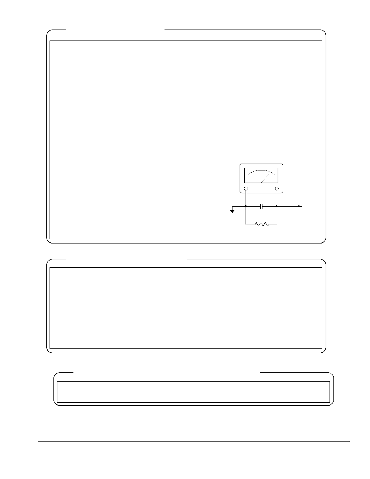
3. Before returning the set to the customer, always perform an AC leakage current check on the exposed
metallic parts of the cabinet, such as terminals, screwheads, metal overlays, control shafts etc. to be sure
the set is safe to operate without danger of electrical shock. Plug the AC line cord directly into a AC outlet
(do not use a line isolation transformer during this check). Use an AC voltmeter having 5000-ohm per volt
or more sensitivity in the following manner: Connect a 1500-ohm 10W resistor, paralleled by a 0.15-MFD,
AC type capacitor, between a known good earth ground (water pipe, conduit, etc.) and the
exposed metallic parts, one at a time. Measure the AC
voltage across the combination of 1500-ohm resistor
and 0.15-MFD capacitor. Reverse the AC plug at the
AC outlet and repeat AC voltage measurements for
each exposed metallic part. Voltage measured must
not exceed 5.25V(rms). This corresponds to
3.5mA(AC). Any value exceeding this limit constitutes
a potential shock hazard and must be corrected
immediately.
Good earth ground
such as a water
pipe, conduit, etc.
AC VOLTMETER
0.15MFD
Place this probe on
each exposed
metallic part.
1500 ohm
10 watt
PRODUCT SAFETY NOTICE
Many electrical and mechanical parts in this chassis have special safety-related characteristics. These
characteristics are often passed unnoticed by a visual inspection and the protection afforded by them cannot
necessarily be obtained by using replacement components rated for higher voltage, wattage, etc.
Replacement parts which have these special safety characteristics are identified in this manual and its
supplements; electrical components having such features are identified by the international hazard symbols
on the schematic diagram and the parts list.
Before replacing any of these components, read the parts list in this manual carefully. The use of substitute
replacement parts which do not have the same safety characteristics as specified in the parts list may create
shock, fire or other hazards.
ULTRAVIOLET DANGER IN SERVICE MODE
Eye damage may result from directly viewing the light produced by the lamp used in this product. Always turn
off lamp before opening this cover. Ultraviolet radiation eye protection required during servicing.
3
Page 4
SAFETY PRECAUTIONS FOR USER
WARNING
On the product and in the operation manual, precautions are presented to use this equipment safely, in
order to protect you and other persons from injury and to protect from property damage.
Indications and symbols for such precautions are as shown below.
WARNING
Wrong operation or incorrect handling by ignoring this notice may result in
Wrong operation or incorrect handling by ignoring this notice may result in
death or serious injury of users and third parties.
serious injury of users, third parties and damage to property.
First things to be observed
When installing or move the equipment:
Installation or transportation of this equipment shall be entrusted to vendors qualified by " Toshiba
Lightning and Technology ".
Installation and transportation by parties other than qualified dealers may result in injury or damage of the
equipment. Also, improper power connection may result in fire disasters.
For installation notes, please refer to the section entitled "Items to be confirmed with a qualified dealer
before installation".
Items to be observed upon use of this equipment
For abnormality or trouble
WARNING
If during operation the unit emits smoke or odor, cut off the power circuit breaker immediately and
disconnect the power plug from the outlet.
After confirming smoke has stopped, contact your dealer for repair.
If you should continue using the equipment, fire or electric shocks may result.
When no image appears on the screen, cut off the power circuit breaker immediately and disconnect the
power plug from the outlet.
If you should continue using the equipment, fire or electric shocks may result. Contact your dealer for
repair.
If water or a foreign matter should get into the equipment, cut off the power circuit breaker immediately
and disconnect the power plug from the outlet.
If you should continue using the equipment, fire or electric shocks may result. Contact your dealer for
repair.
If the equipment should fall down or the cabinet is broken, cut off the power circuit breaker immediately
and disconnect the power plug from the outlet.
If you should continue using the equipm ent, fire or electric shocks may result. Contact your dealer for
repair.
4
Page 5

Equipment Use
SAFETY PRECAUTIONS FOR USER
WARNING
Do not remove the rear cabinet cover, as there are high-voltage parts in the unit. Touching components
inside may result in electric shocks.
End user should not repair or reconstruct the equipment.
Never attempt to do so, otherwise fire disaster or electric shocks may result. For repair, contact your dealer.
Do not damage, break, modify, bend forcibly, tug, t wist, bundle, place heavy weights on or heat the power
cable.
If the equipment is used with damaged power cable, fire disaster or electric shocks may result.
If the cable is damaged, contact your dealer for repair.
Do not insert or drop metals, liquids or combustible materials into the equipment through the vent holes,
etc. Fire disaster or electric shocks may result.
Do not place items on the equipment. These may fall from the unit, resulting in injury or other damage.
Do not obstruct any of the ventilation holes. Should metals or liquids get into the equipment, fire or electric
shocks may result.
Do not humidify the atmosphere around the unit. Do not place a humidifier near or under the unit.
High humidity may cause fire or electric shocks. Also, the screen may be degraded and broken, resulting in
injury.
CAUTION
When disconnecting the power plug, do not pull the power cable.
Make sure to hold the plug to disconnect. If you pull the cable, the cable may be damaged, causing fire or
electric shocks.
Do not connect/disconnect the power plug with wet hands. It may cause electric shocks.
Do not step on the equipment, or place heavy items on it.
This may cause the unit to fall possibly causing injury or damage, which may also cause fire or electric
shocks.
When leaving the equipment out of use for a long time, make sure to disconnect the power plug from the
outlet for safety.
When the power supply is turned off by the controller and the equipment is placed in “stand-by” mode,
electricity is still consumed and parts of the circuitry are still “live”.
If the equipment is not to be used for extended periods, shut off the power by main power switch and isolate
from the main power supply to avoid any unexpected problems, which may cause fire or other damage.
Do not block the vent ports of the equipment, or obstruct airflow around the equipment.
When the vent ports are blocked, temperature inside will rise and cause fire disaster. For example, avoid
using the equipment under the following conditions.
(1) Cover the equipment with a cloth or curtain.
(2) Place packages around the equipment or stand things against the equipment.
(3) Operating the equipment in an enclosed cabinet, without adequate ventilation.
(4) Operating the equipment in a manner or environment outside the published specifications.
Do not expose the equipment to oily smoke or steam, or use the equipment in dusty atmosphere.
Do not expose the equipment to wind and rain. This may cause damage to the unit, which can result in
electric shocks or other injury.
The screen may drop or fall down due to wind, excessive vibration etc. and cause injury or damage.
5
Page 6

For servicing, maintenance and inspection
SAFETY PRECAUTIONS FOR USER
WARNING
If dust or dirt is visible on the blades or the blade clamping face of the power plug, clean the plug or blade
clamping face before connection. Otherwise, fire may occur due to lowering of insulation of the power plug.
CAUTION
Make a maintenance contract with the dealer and entrust the dealer with periodical inspection and
adjustment.
If the equipment is left for long time without cleaning, dust inside the equipment may build up and the unit
may malfunction, possibly causing fire, electric shocks or other third party damage.
Servicing of the equipment must only be performed after disconnecting the power plug from the outlet.
Otherwise electric shocks resulting in death or injury may occur.
Pay attention to all connection cables. Injury may occur by being caught by or stumbling on the cables.
In addition, the equipment may fall down, resulting in injury or damage.
Items to be confirmed with the qualified dealer before installation
WARNING
This equipment has been designed exclusively for indoor use. Do not use the equipment
outdoors; fire or electric shocks may result.
Do not install the equipment on or in unstable locations. The equipment may drop or fall down, resulting in
injury.
When mounting the equipment on a wall or other vertical surface, ensure that all fixings are secure and that
the surface the equipment is being fastened to, is perpendicular and capable of supporting the additional
lord.
When mounting the equipment from a ceiling or other overhead horizontal surface, ensure that all fixings
are secure and able to support the load. Also ensure that the horizontal surface can support the additional
load and that any fixings used do not cause a trip or other safety hazard.
Confirm that the installation procedure are undertaken with sufficient allowance and consideration for the
total weight/load of all the units installed in the event of outside influences such as earthquakes, explosions
or other factors.
Always ensure that installation does not cause or create a safety hazard by being placed too low, so that a
passer-by can hit the unit with their head or other body part by accident.
If the installation is unstable, the equipment may drop or fall down, resulting in injury.
Do not install the equipment at places exposed to direct sunshine, or where temperature rises, such as a
place near heater, etc.
If the temperature inside the equipment rises, fire may result.
Do not use the equipment in places with high humidity, such as a bathroom or a place nea r a humidifier.
It may cause fire or electric shocks. Also, the screen may become broken, resulting in injury.
Do not use the equipment with power voltages other than the one indicated on the equipment.
otherwise, fire or electric shocks may result.
Ma ke sure to install a circuit breaker in the power supply line exclusively for the equipment.
otherwise, fire may occur because the power supply cannot be cut off immediately when trouble or
abnormality occurs in the equipment.
The socket-outlet shall be installed near the equipment and shall be easily accessible.
6
Page 7
SAFETY PRECAUTIONS FOR USER
Make sure to provide ground line from the ground terminal of the power plug.
Otherwise, electric shocks may result.
Always calculate the total loading of any installed equipment and ensure that the power supply, (sockets or
other outlets) are suitable for the installation. Failure to do so may cause fire or electric shocks due to
overload.
Do not place or store anything on the equipment. If metals, liquid or other objects should get inside the
equipment, fire or electric shocks may result. Also, any heavy items placed on the top of the units may fall
down, resulting in injury or damage.
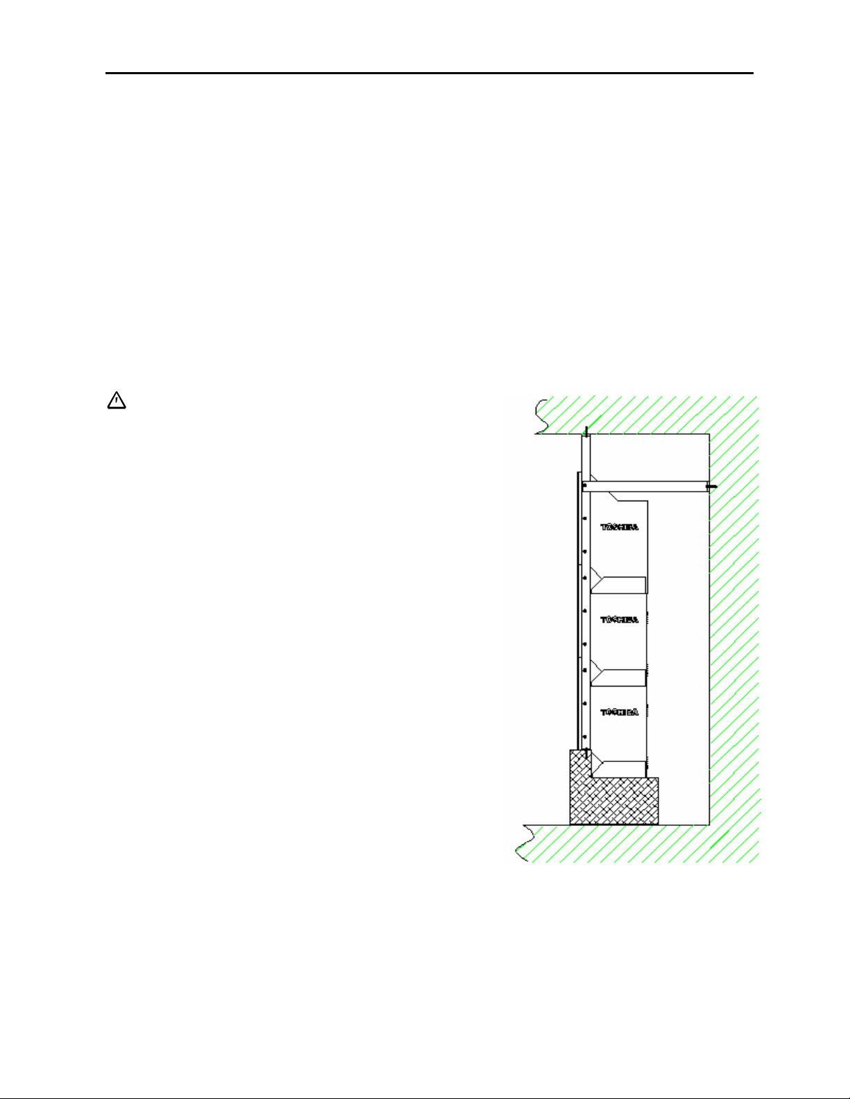
Secure the equipment to the building. The wall to be attached needs to have strong and rigid construction.
A high position projection system may topple during an earthquake. Human life and property may sustain
great damage if a system topples. Prevent toppling and accidents. Following offers some examples of how to
avoid topplin g. Use the most appropriate one for the installation conditions.
CAUTION
Do not block the vent ports of the equipment, or obstruct
airflow around the equipment.
When the vent ports are blocked, temperature inside cube
will rise and cause fire disaster. For example, do not use
the equipment in the following conditions.
(1) Install the equipment in places with poor ventilation.
(2) Place the equipment facing up, sideways, or upside -down.
(3) Place the equipment on a carpet or bedding.
(4) Cover the equipment with a cloth or curtain.
(5) Place packages around the equipment or lean/place items
against the equipment.
(6) Placing the equipment on a table, unstable base or directly
against a wall. Rear access is required for periodic
maintenance or inspection.
(7) Do not place the equipment where it may be exposed to
dust, oily smoke or steam such as a cooking area, etc..
(8) Do not place the equipment where it may be exposed to
wind and rain.
The screen may drop or fall down due to wind and cause
injury. Or rain may result in fire or electric shocks.
7
Page 8

PRECAUTIONS FOR USE AND MAINTENANCE
Request to User
Plastic Screen
The P503DL screen is made of a plastic material and can be easily scratched. During manufacture and
packing, every care is taken to ensure that no hard objects that could scratch or otherwise cause damage are
allowed to touch the screen when opening the carton box and taking out the product. Please exercise
caution, when unpacking the unit to prevent the packing material or other items from scratching and
rubbing the screen to avoid (i) damage to the screen and (ii) generation of static electricity which may attract
dust particles onto the screen.
Precautions on Use
Connection of a grounded cable
Ground the projection unit in order to prevent electric shock with 3-core power cable. There is greater danger
of electric shock when multi projection units are used without ground wire connected.
Condensation
When room temperature rises rapidly (or the Dat a Display projection unit is moved from a cold place to a
hot place), condensation may form on the lens, causing picture distortion or color fade-out. In such case, wait
for a while (with keeping power ON) until the condensation clears.
About cooling fan and color wheel motor
The axial cooling fan and also color wheel motor in the projection unit should be considered a consumable
item and need to be replaced after about one or two years of use or whenever noise or other symptoms of
breakdown are apparent. Contact your dealer for the replacement work.
** Air filter equipped at air intake needs periodical cleaning. A clogged air filter will result in temperature
build up inside the P503DL cabinet. Possibly in excess of stated operating specification, th is may lead to
malfunction or reduced equipment life.
Maintenance
Do not use solvent or paint thinner
If these are used, coating layer may peel off or deteriorate. If rubber or plastic comes into contact with the
projection unit for a long time, the projection unit may be stained.
Care of the screen
After switching the power supply off, gently wipe the screen with a soft cotton cloth. Since the screen
surface is easily scratched, this may also build up an electronic static charge. Do not rub it with a hard
object; the screen may be easily damaged. Never use a chemical duster.
Care of the cabinet
After switching the power supply off, wipe gently with soft cloth.
When using a chemical duster, follow the maker's precautions.
Care of the air filter
The air intake filter should be regarded as a consumable and changed on periodic bases, depending on the
operating conditions. If or when the filter becomes clogged (by oily smoke etc) replacement of the filter is
recommended.
For a temporally remedy, the filter may be cleaned by an oil removal cleaner, detergent used in a kitchen
or a diluted vinegar solution.
8
Page 9

GENERAL DESCRIPTIONS
FEATURES
l Digital Light Processing TM (DLP TM) by Texas Instruments
P503DL is a projection unit using the Texas Instruments’ Digital Mirror Device (DMD) TM optical element.
The DLP TM, Digital Light Processing TM engine is constructed with the DMD chip, with XGA resolution.
l Input capability
From PC video output card, SVGA signal is best suitable but some others are also compatible.
Incoming PC signal timing should be followed the VESA standard.
SVGA signal is reproduced on screen without having any scaling function.
The other frequencies are converted to XGA resolution inside the cube. See note 1.
In case of SXGA resolution such as 1280x1024, an original aspect ration of 5:4 is changed to DLP aspect
ratio of 4:3 so that picture may have different shape in this resolution.
l Internal magnification
A multi -screen system can be formed easily with an internal magnification up to x6 magnification.
l Superior image quality
* Native resolution of XGA, 1024 x 768 pixels
* No burn-in unlike projection tube
* High Contrast image by 12 -degree mirror flip Double Data Rate DMD chip
l Easy installation and maintenance
* Convergence free between colors
* Steady geometric alignment
* Engine installed at factory
l Easy replacement 10,000/6000 H (Survival rate of 50%) UHP 100/120W selectable lamp power,
See note 2
l Low power consumption
100W UHP lamp is used for light source, ballast power selection of 100W/120W is possible.
Total power consumption is less than 200W.
l Highly reliable control system
Projection system can be controlled with a PC via RS232C cable. Also most of the
control/adjustment is possible to do with optional wired remote control, CT-90000.
RS232C IN/OUT are equipped to send command and also for communication between cubes.
l Mechanical function
Screen escutcheon can be removed from front. The mullion size is 1.0mm. When adjacent cube
is attached, total mullion size becomes 2.5mm including gap in between.
Note 1: This does not mean that all the signals are accepted. For acceptable signals, refer to the later page in
Note 2: The lamp is expected to last more than 8000H, with the recent information, it will be more than 10000H, with
Acceptable Signal Type and also Acceptable RGB input Signal Timing.
survival rate of 50% at 100W power selection, however, the actual life of each lamp varies depending on
conditions of use. For warranty and exchange of lamp, please check with your dealer/distributor.
9
Page 10
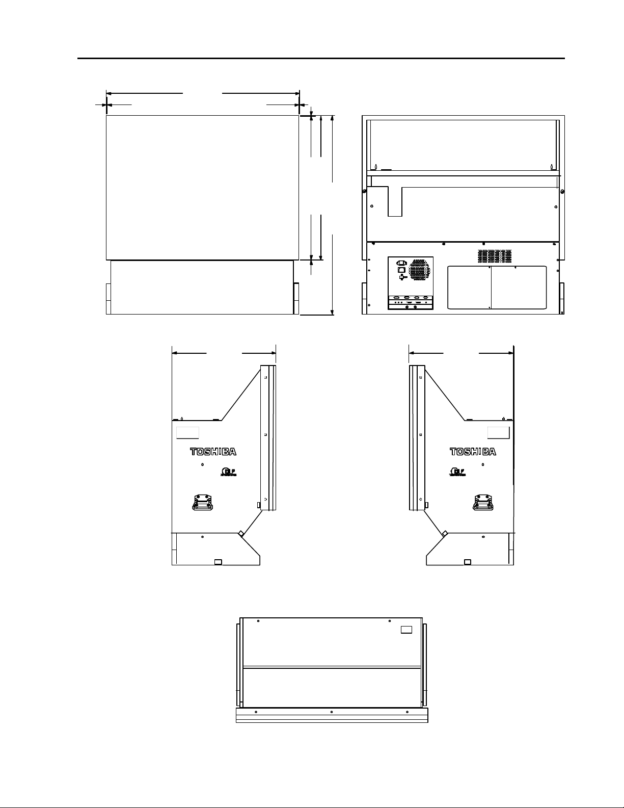
P503DL DIMENSIONS
Size: mm (inch)
Front Rear
[? ? ]
0.5 (0.02)
1016 (40.0)
0.5 (0.02)
0.5 (0.02)0.5 (0.02)
762 (30.0)
Side
550 (21.7)
[? ? ]
Top
[? ? ]
1050 (41.3)
550 (21.7)
[? ? ]
10
Page 11
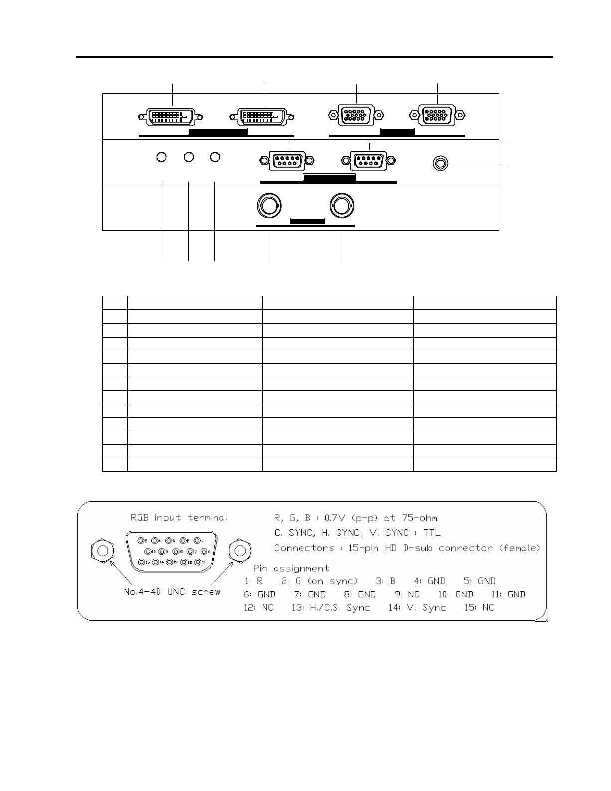
FUNCTION OF I/O PANEL
(7)
(6)
(5)
(10)
(11)
(1) (2) (3) (4)
OUT IN RGB 2 RGB 1DIGITAL SIGNAL LINK RGB INPUT
POWER FAN LAMP REMOTE
OUT
CONTROL RS-232C
VIDEO
(8)
(9)
INOUT
IN
No. Name Function Remarks
1 DVI Digital Output DVI Link (switched) Output Digital pins of DVI connector
2 DVI Digital Input DVI Input (Link or PC) Digital pins of DVI connector
3 RGB-2 Inp ut terminal RGB-HV signal Input D-sub HD 15 -pin (female)
4 RGB-1 Input terminal RGB-HV signal D-sub HD 15 -pin (female)
5 Power Indicator Power status indication Green/Red two colors LED
6 Fan Indicator Fan status indication Green LED
7 Lamp Indicator Fan status indication Green LED
8 RS232C Output RS232C Communication D-sub 9- pin (male)
8 RS232C Input RS232C Communication D-sub 9-pin (female)
9 Remote control Input jack Wired remote control 3.5mm stereo Mini Jack
10 Video Output Composite Video thru- Output BNC connector
11 Video Input Composite Video Input BNC connector
Note: Video signal: not fully compatible
Basic model does not include Video input terminal since the moving picture displayed with this
unit may not have full compatibility and picture will not display all the pictures supplied, it may
appear as missing field, picture lacks smooth movement
11
Page 12
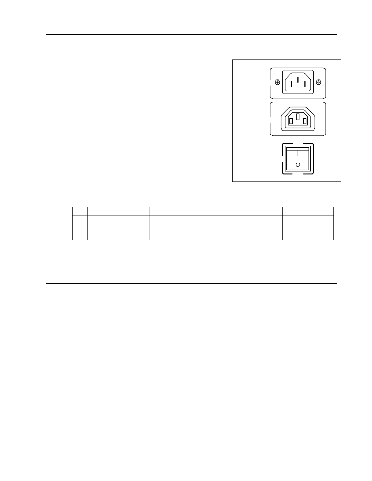
FUNCTION OF POWER PANEL
No.
1
2
3
Note 1: The AC outlet supplies un- switched power source to a
second unit in a multi-projection system.
Do not use it for any other purpose. Serial connection
using this power outlet must be maximum of four units
including the 1st unit.
Note 2: The plug type of the projection unit power cable may not
AC INLET
AC100~ 240 50/60Hz
AC100~ 240 50/60Hz
match the AC outlet. When power is to be supplied
to another unit from this AC outlet, please purchase
necessary power cable.
AC OUT INLET
UNSWITCHED 8A MAX
Note 3: About Power Supply cord
The Power Supply cord must be in accordance with
the applicable standards.
A three-core cord, one for ground, must be used.
POWER
The power cord must be at least 1.0mm2 and H05VV-F.
Name Function Remarks
Power Switch Turn ON and OFF main power ON/OFF
AC Inlet AC 100-240V, 50/60Hz input 3P plug
AC Outlet AC outlet, un -switched, max 8A 3P socket
POWER SWITCH AND POWER INDICATOR
AC power source is turned-on/off with the Power Switch. When the Power Switch is turned-on, the Power
Lamp LED Indicator lights in green, Fan indicator by green and some periods later, green at Lamp when
lamp is ON and the projection unit enters active state.
It takes about 30 seconds typically till an image is shown after Power Switch is turned -on.
In the active state, it is possible to power on/off with an external controller. When power is turned-off with
an external controller, the Power Indicator LED lights in red color and a projection unit enters standby
state.
Interval from turn-off to turn-on shall be more than 30 seconds. If the interval is not enough, the lamp
may not strike, longer the wait time, lamp life risk becomes less. If the user continues to repeat this
short wait re-strike, it may shorten the life of the lamp.
The power/lamp/fan indicators also indicate failure information of the projection unit by blinking light.
The later page at appendix list shows the lamp status.
( 2)
( 3)
ON
(1 )
OFF
12
Page 13
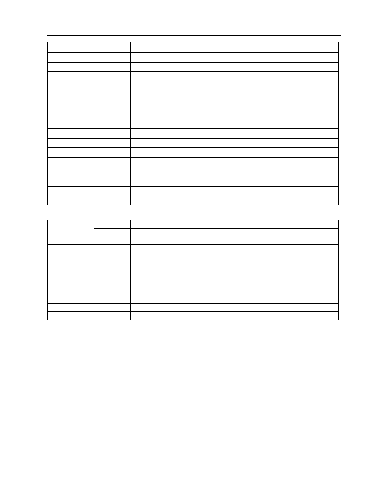
SPECIFICATIONS
Model name P503DL
Type 50- inch rear projection unit
Acceptable signals Refer to page 13 and page 14.
Image device 1 chip XGA Digital Mirror Device
Light source 100W/120W switch selectable UHP lamp
Resolution 1024 x 768 dots (Include part hidden with screen frame)
Brightness 500cd/m2 (Typ.) by 120W operation
Screen Fresnel sheet (internal), Lenticular sheet (external)
Screen frame 1 mm average (2.5mm between cubes when two are attached)
Viewing Angle Horizontal: Min. 150 degrees, Vertical: Min. 60 degrees
Operating temperature 5 -35 ? (41-95 F)
Operating humidity 30-70 % (Relative humidity non-condensing)
Power requirement AC100-240V, 50/60Hz, 200W (200VA)
Dimens ions 1016 (W) x 1050 (H) x 550 (D) mm (40.0 x 41.3 x 21.7 inch)
Weight about 63kg (139 lbs)
Accessories Owner’s Manual, Assembly screws
Video Input Terminal Video Composite Input: BNC
Level Video Input: 1.0Vp-p composite video, PAL/NTSC
DVI Input DVI signal from PC or Link, No HDCP compatible
RGB Inputs Terminal RGB input: HD D-sub 15pin (female) connector
Level R/G/B signal: 0.7Vp-p (75-ohm termination)
H.SYNC / V.SYNC signals: TTL
External control System: RS-232C, Terminal: D- sub 9pin (female) connector x 1
Speed: 1200, 2400, 4800, 9600 baud
Communication Link System: RS-232C, Terminal: D -sub 9pin connector x 2 for IN and OUT
Remote Control Terminal 3.5mm terminal for optional CT-90000 Remote Controller
The DVI i nput is compatible for PC signal but for 1080i HDCP.
DVI connector and RS232C cables are included as accessories. RS232C cable is common type and if
cubes are assembled more than 10 sets, RS232C communication error may become obvious by means of
its standard, length limitation. In such case, using better and thicker wire may extend the cable length
or possibly use buffered splitter and separate the wiring into two or more branch will result better
communication.
DVI output signal is possible to make link for any selected input but this DVI output comes after its
frequency converted digital output, having several frames of signal delay. Thus quick movement
such as moving video may result signal delay added by each cubes and picture may not match while
moving image displayed.
The specifications and design of this product are subject to change without notice.
(R)
Double Data Rate type
13
Page 14

ACCEPTABLE SIGNAL TYPE
59.94
50.00
55.90
85.08
60.02
The following are acceptable input signal types. Projection unit automatically distinguishes mode
according to frequency of input signal. All the signals accepted are displayed on screen with 1024x768 dot
by internal resolution converter. The Digital Signal Link function may not support NTSC/PAL/SECAM
signal supplied from RGB-1 and RGB-2 input terminal. Also, Digital Signal Link function may not
support unstable signal either.
Format Type Mode H. Freq. V. Freq. Input Sync Pol. Scan Type Input
Resolution H/V Terminal
NTSC 358-443 Standard NTSC2 15.734
PAL SECAM PAL2 15.625
NEC PC98 @56Hz NEC- 24k 24.820
VGA Graphic 350 lines @70Hz Text- 70 31.469 70.087 640 x 350
VGA Graphic 400 lines @70Hz Text- 70 31.467 70.087 640 x 400 N/P Non interlaced RGB IN
VESA 640 x 350 @85Hz TEXT85 37.861
VESA 640 x 400 @85Hz TEXT85 37.861 85.080 640 x 400
VESA 720 x 400 @85Hz TEXT85 37.927 85.039 720 x 400
VGA 640 x 480 @50Hz VGA50 26.250 50.000 640 x 480 N/N Non interlaced RGB IN
VESA 640 x 480 @60Hz VGA60 31.469 59.940 640 x 480
VESA 640 x 480 @72Hz VGA72 37.861 72.809 640 x 480
VESA 640 x 480 @75Hz VGA75 37.50 75.000 640 x 480
VESA 640 x 480 @85Hz VGA85 43.269 85.008 640 x 480
Macintosh 13 Inch Mode @67Hz MAC13 35.000 66.667 640 x 480
SVGA 800 x 600 @50Hz SVGA50 31.400 50.000 800 x 600 N/N Non interlaced RGB IN
VESA 800 x 600 @56Hz SVGA56 35.156 56.250 800 x 600
VESA 800 x 600 @60Hz SVGA60 37.879 60.317 800 x 600
VESA 800 x 600 @72Hz SVGA72 48.077 72.188 800 x 600
VESA 800 x 600 @75Hz SVGA75 46.875 75.000 800 x 600
VESA 800 x 600 @85Hz SVGA85 53.674 85.061 800 x 600
Macintosh 16 Inch Mode @75Hz MAC16 49.725 74.550 832 x 624
XGA 1024 x 768 @50Hz XGA50 40.300 50.000 1024 x 768 N/N Non interlaced RGB IN
VESA 1024 x 768 @43Hz XGA43 35.522 43.479 1024 x 768 P/P Interlaced RGB IN
VESA 1024 x 768 @60Hz XGA60 48.363 60.004 1024 x 768 N/N Non interlaced RGB IN
VESA 1024 x 768 @70Hz XGA70 56.476 70.069 1024 x 768 N/N Non interlaced RGB IN
VESA 1024 x 768 @75Hz XGA75 60.023 75.029 1024 x 768 P/P Non interlaced RGB IN
VESA 1024 x 768 @85Hz XGA85 68.677 84.997 1024 x 768 N/N Non interlaced RGB IN
Macintosh 19 Inch Mode @75Hz MAC19 60.135 74.700 1024 x 768 N/N Non interlaced RGB IN
SXGA 1280 x 1024 @50Hz SXGA50 53.000 50.000 1280 x 1024
VESA 1280 x 1024 @60Hz SXGA60 63.981.
VESA 1280 x 1024 @75Hz SXGA75 79.976 75.025 1280 x 1024
SEGA 640 x 480 @60Hz SEGA60 31.678 79.770 640 x 480 N/N Non interlaced RGB IN
Bowling 430 x 252 @60Hz 15.78 15.780 60.692 430 x 252 N/N Non interlaced RGB IN
Timing C 640 x 480 @60Hz Tri-F60 31.469 59.941 640 x 480 N/N Non interlaced RGB IN
480p 720 x 480 @60Hz 480p 31.542 60.080 856 x 525 N/N Non interlaced RGB IN
720p 1280 x 720 @60Hz 720p 45.000 60.000 1650 x 750 N/N Non interlaced RGB IN
EDTV 720 x 480 @60Hz EDTV 31.469 59.941 858 x 525 N/N Non interlaced RGB IN
Note 1: In composite sync or sync- on-green signal, H sync signal must be inserted into V sync signal.
No good Good
N/N Interlaced Video IN
N/N Interlaced Video IN
640 x 400
640 x 350
1280 x 1024
N/N Non interlaced RGB IN
P/N Non interlaced RGB IN
P/N Non interlaced RGB IN
N/P Non interlaced RGB IN
N/N Non interlaced RGB IN
N/N Non interlaced RGB IN
N/N Non interlaced RGB IN
N/N Non interlaced RGB IN
N/N Non interlaced RGB IN
- / - Non interlaced RGB IN
P/P Non interlaced RGB IN
P/P Non interlaced RGB IN
P/P Non interlaced RGB IN
P/P Non interlaced RGB IN
P/P Non interlaced RGB IN
- / - Non interlaced RGB IN
N/N Non interlaced RGB IN
N/N Non interlaced RGB IN
P/P Non interlaced RGB IN
Note 2: In H/V separation sync signal, V sync signal must not be included H sync signal or equalization
pulse. Also, H sync signal must not included V sync signal and equalization pulse.
14
Page 15

V sync signal
59.94
50
85
118
TEXT70
48
382
TEXT70
48
132
TEXT70
54
382
TEXT70
54
132
TEXT85
96
323
TEXT85
96
13
TEXT85
13
40
50.00
182
40
59.94
182
173
75
13
80
13
96
86435
33
88
1056
14
1024
56.2536
12
88
1056
14
64
1040
376
1056
75
13
1048
13
224
1152
74.55
13
No good Good
No good (Equalization pulse)
H sync signal
Note 3: When composite sync or sync-on- green signal is supplied, horizontal frequency must be 31 kHz or
higher.
Note 4: Sync signal : Horizontal Positive or Negative. Minimum H. sync width : 1µS
Vertical Positive or Negative. Minimum V. sync width : 2H
ACCEPTABLE RGB INPUT SIGNAL TIMING
Following are acceptable RGB input signal timings which have been tested by Toshiba. These are timings
checked on the RGB input terminals of projection unit. If signal supplied is not exactly the same as one of
the followings but is simile to one, it may be accepted by adjustment of projection unit.
When picture caused horizontal jitter or display position difference, adjust the projection unit with optional
controller. However, when signal cable used or other factors have problems, timing may cause trouble and
picture will not be stable. When signal is not stable, each function of projection unit will not be guaranteed
for good picture display.
R,G,B
H.Sync
Mode Input A B C D E fH fV Clock G H I J K
Resolution
NTSC 2 15.734
PAL 2 15.625
NEC24
k 640 x 400
640 x 350
640 x 400
720 x 350
720 x 400
640 x 350
640 x 400
720 x 400 108 720 36 72 936 37.927 85.039 35.500
VGA50 640 x 480
VGA60 640 x 480
VGA72 640 x 480 120 640 32 40 832 37.861 72.809 31.5
VGA75 640 x 480 120 640 16 64 840 37.5
VGA85 640 x 480
MAC13 640 x 480
SVGA5
0 800 x 600
SVGA5
6 800 x 600 128 800 24 72
SVGA6
0
SVGA7
2 800 x 600
SVGA7
5 800 x 600 160 800 16 80
SVGA8
5
MAC16 832 x 624
800 x 600
800 x 600 152 800 32 64
(Pixels) (Pixels) (Pixels) (Pixels) (Pixels
Horizontal Timing
A B C
R,G,B
V.Sync
D
640 59 64 848 24.820 55.900 21.053
640 14 96 800 31.469 70.087 25.175
640 14 96 800 31.469 70.087 25.175
720 18 108 900 31.469 70.087 28.322
720 18 108 900 31.469 70.087 28.322
640 32 64 832 37.861 85.080 31.500
640 32 64 832 37.861 85.039 35.500
640 24 96 800
640 24 96 800 31.469
640 56 56 832 43.269 85.008 36
640 64 64
800 40 128
800 40 128
800 56 120
832 32 64
E
) (kHz) (Hz) (MHz) (Lines) (Lines) (Lines) (Lines) (Lines)
26..25
0
66.667 30.24
31.40 50.0 33.158
35.156
37.879 60.317 40
48.079 72.188 50
46.875
53.674 85.061 56.25
49.725
15
Vertical Timing
G H I
J
16.521
16.406
21.00
25.175
31.5
49.5
57.283
K
25 400
60 350
35 400
60 350
35 400
60 350
41 400
42 400
25 480
25 480
20 480
16 480
25 480
39 480
23 600
22 600
23 600
23 600
21 600
27 600
39 624
440
449
449
449
449
445
445
446
525
525
520
500
509
525
628
625
628
666
625
631
667
Page 16

1024
1344
36
1024
1344
60.004
36
144
1024
1328
36
1024
1312
13
1024
1376
13
1024
1328
43
1280
1688
13
1066
1280
1688
60.02
13
1066
1280
1688
13
1066
87
143
46
24
96
56
96
1024
1650
55
59
66
A C
? ?
A C
? ?
Wired remote control
RGB
-
2 signal
AC power
This is one of the example of connection
XGA50 1024 x 768 160
XGA60 1024 x 768 160
XGA70 1024 x 768
XGA75 1024 x 768 176
XGA85 1024 x 768 208
MAC19 1024 x 768 172
24 136
24 136
24 136
16 96
48 96
34 96
40.30 50.0 54.163
48.363
65
56.476 70.069 75
60.023 75.029 78.75
68.677 84.997 94.5
60.135 74.7 79.86
29 768
29 768
29 768
28 768
36 768
30 768
SXGA5
0
1280 x 1024
248
48 112
53.30 50.0 89.97
38 1024
SXGA6
0 1280 x 1024
248
48 112
63.981
108
38 1024
SXGA7
5 1280 x 1024
248
16 144
79.976 75.025 135
38 1024
SEGA6
0
640 x 480
15.78 430 x 252
Tri-F60 640 x 480 116 640 38 64 858 31.469 59.941 27.000
480p 720 x 480
720p 1280 x 720 270
EDTV 720 x 480
640 43 82 852 31.678 59.770 26.990
430 10 33 519 15.780 60.692 8.190
720 16 64 856 31.542 60.080 27.000
260 96
45.000 60.000 74.250
720 16 63 858 31.469 59.941 27.000
33 480
2 252
30 480
30 480
20 720
33 480
Note 1: The clock pulse is made in projection unit automatically. External clock input is not equipped.
Note 2: When 15kHz NTSC/PAL signal is supplied to the RGB input terminal, the Digital Signal Link function is not guaranteed for correct
signal transfer.
Note 3: When signal except standard type (for example, played back software with a copy guard or a special effect play of VCR, etc.) is
supplied to the RGB input terminal, projection unit may not function properly.
CONNECTION AT A MULTI PROJECTION SYSTEM
806
806
806
800
808
805
530
260
525
525
750
525
? ? ? ? ? ? ? ? ?
R G B? ? -1
RG B? ? -2
? ? ? ? ?
Video signal
OUT IN RGB 2 RGB 1DIGITAL SIGNAL LINK RGB INPUT
AC INLET
15A 125V/250V AC
AC OUTLET
AC100V-240V 50/60Hz
UNSWITCHED MAX 10A
A C ? ?
RGB-1 signal
OUT IN RGB 2 RGB 1DIGITAL SIGNAL LINK RGB INPUT
AC INLET
15A 125V/250V AC
AC OUTLET
AC100V-240V 50/60Hz
UNSWITCHED MAX 10A
Digital Lin k
DIGITAL SIGNAL LINK RGB INPUT
CONTROL RS-232C INOUTPOWER FAN LAMP REMOTE
VIDEO
OUT IN
OUT IN RGB 2 RGB 1
RS232C link
Unit-4 Unit-3
AC INLET
15A 125V/250V AC
AC OUTLET
AC100V-240V 50/60Hz
UNSWITCHED MAX 10A
A C ? ?
CONTROL RS-232C INOUTPOWER FAN LAMP REMOTE
VIDEOOUT IN VIDEOOUT IN
Unit-1
OUT IN RGB 2 RGB 1DIGITAL SIGNAL LINK RGB INPUT
Unit-2
AC INLET
15A 125V/250V AC
AC OUTLET
AC100V-240V 50/60Hz
UNSWITCHED MAX 10A
AC power
CONTROL RS-232C INOUTPOWER FAN LAMP REMOTE
VIDEOOUT IN
CONTROL RS-232C INOUTPOWER FAN LAMP REMOTE
16
for a multi-projection system using four
projection units.
In this example, signal sources are
supplied from composite video signal to
video-card and signal from a PC is
connected to each cubes by signal links.
The optional wired remote controller is
connected to Unit-1 and all the units
could be controlled by the remote
control through System Bus-Link when
RS232C communication links are daisy
chain connected.
The final RS232C output should not
return to 1st cube.
When both, RS232C control signal and
CT-90000 wired remote control are
connected, the remote control has a
priority over PC, RS-232C connection
thus PC control is not possible.
AC power source
This can be also possible to link up to 4 sets
by separately purchasing 6ft monitor power
interconnect cable
MULTIPLE CONNECTION
Page 17

Left side
Note: Maximum len
gth of the RS232C cable in total length is about 20
-
30 meters.
With this model DVI output is possible to form signal link connection by daisy
-
chain connection of
If the length becomes much more than its specification, the communication error may occur.
When some miss-reading of commands start to occur, then use better quality wire than its standard
may reduce trouble and possible to extend the communication wire length.
Using RS232C signal buffer distributor and separate the cable connection into two or more will also
Reduce miss- communication troubles.
DVI cables. When this feature is used, several frames of signal delay will occur by each cube’s
electronic circuit so that when moving picture is supplied, picture junction may not match.
When the set is opened from its carton box, 1st thing to do is to
remove the screen protection metal plate attached at the corners.
Note: * Pay attention not to touch the screen.
* When temporally place the screen, avoid screen
Screen protectors
? ? ? ? ? ? ? ? ? ? ?
touching to the other objects or materials.
The screen is locked by small tab at sides and screw attached
to the tab need to rotate to un-lock the screen frame.
The picture shows the
screws which are vertical
Screen Lock screws
Right side
slit, this position make
the screen lock released.
When this screw slit is
rotated to 90-deg. horizontal,
the screen frame is locked.
Another arrow with two points
Indicat e the push rod position.
3)
Screen Lock screw The screen can be removed by
? ? ? ? ? ? ? ?
holding both sides of the frame
and pull forward gently.
When wall assembled, then it
3)
2)
1)
is impossible to hold both sides
3)
of the frame thus, one person at
? ? ?
Guide rail front and another person at back
and at back person needs to push
the rod by long push pole.
3)
Any long push bar or pole can be
Screen Assembly used but strong, not easily bend
? ? ? ? ? ? ? ? ?
pole is needed.
3)
MULTIPLE CONNECTION
When attaching the screen, confirm the screen lock screw slit if it is placed vertical position so that the
17
Page 18

screen lock is un-locked and open before attaching the screen.
This is an example of 4 sets attached together by 2x2 configuration. When 4 sets are combined together
with the screws fastened, a gap between cubes becomes small and also stable for entire wall.
The internal locking screws need to be fastened while front screen has removed, carefully watching
frame of each cubes. Do not tighten the screws very strong, aluminum frame may be deformed by
such strong fastenings.
M8 screw 20mm long Hex key screw
Tightening torque: 20-25N.m
At the back of the each cubes, there are two small
plates located top portion at both sides and they
can be used to fasten cubes horizontally or vertically
for rear enforcement.
To do this, remove one of the screw, make loose for
another and rotate the plate then fasten to adjacent
cubes together.
As for the connection of wires, refer to the previous page, page 15 for one of the example.
The following left example shows the connection to use internal magnification capability and right
Example indicates the combination with external signal processor.
18
Page 19

DISASSEMBLE
? ? ? ? ? ? ?
? ? ? ? ? ? ?
e: When the lamp unit is not placed correctly, brightness or other picture performance may not be
DISASSEMBLY
Lamp housing
L
amp unit
Note: Lamp housing and Lamp may be
5) Attach new lamp at the
1. HOW TO REPLACE THE LAMP
1) Turn off the power switch and disconnect AC cord.
Make loose 3 screws at the lamp door.
2) Open Lamp door as right picture arrows show.
3) Rotate Locking Lever as shown as
arrow (1) below.
4) Gently pull the lamp housing
?
to the right as picture below, Lamp door screws
arrow (2) shows.
?
Lamp door
Screws are shown enlarged
hot, be careful when touch to it.
?
?
Do not touch lamp glass shield, an
oil particle from finger may affect
picture quality or lamp may be
damaged.
Wipe and clean lamp glass shield
?
?
?
? ? ? ? ?
surface before its installation if it
was not clean.
Lock Lever
guide rail shown as right
Lock lever
then slide as arrow (1) shows.
Lock lever needs to be at un-lock
?
position, then push in the lamp
holder at the right place.
Lock the Lock ring by lock lever
as arrow (2).
?
Lamp Unit
Not
Achieved to the specification. Make sure that the lamp is nicel y fit and fastened.
Check also if the lamp power supply connector is securely inserted.
6) Attach lamp door.
7) Turn ON the power switch, connect PC with software, Cube commander, or remote control, then
enter to the ADJUST mode à SPECIAL mode à F à STD thus the lamp timer is reset.
? ? ? ? ? ?
Guide rail
19
Page 20

? ?
2. AIR FILTER
Air filter needs to be maintained periodically by washing it or replace when the filter is damaged.
1) Turn off the power switch and remove one screw.
2) Lift up and pull the air filter case from its pocket
as arrow in the picture shows.
3) Wash and clean the filter and dry it.
3. Place the clean filter at its original place.
4.Fasten the screw.
Note:
This filter cleaning may be necessary to check and clean
in every 3 months of period.
Filter case
Continuous usage of clogged filter will affect to raise the internal
temperature and may reduce the life of the components. Screw
3. CABINET DISASSEMBLE
1) When mechanical position adjustments are needed, only the small door may be open to do.
This is located at almost center position.
Right side is lamp replacement door which
has door switch to shut off lamp when
opened.
2) When all the mechanism and electronics
area to be shown, then, the rear panel
needs to remove as right picture.
3) Location of the light engine or other
parts, the next chapter explains them.
Front and rear portion are fastened with
many screws to avoid electronic emission
radiation.
Use all the parts and screws to assemble to
have the same condition and reduce excessive
emission from the electronics parts.
Refer to next page picture for following
When Lamp ballast needs to remove, take 3 screws
out and pull it up. When I/O control box needs to be removed, after removing screws, pull
forward a little, sometimes, it may be convenient to remove ballast unit before this.
? ?? ? ? ? ? ?
DISASSEMBLE
20
Page 21

4. LOCATION OF KEY COMPONENTS AND FUNCTION MODULE
Power
module
Lamp Ballast
(A) Left-Right position adjustment
This illustration indicates the key components
? ? ? ? ? ?
? ? ? ? ?
Power Module
Control Module
Lamp power
DLP? ? ? ?
(1)..... ? ? ? ? ?
(2)..... D M D? ? ? ?
shown after rear panel has removed.
? ? ? ? ? ? ?
? ? ? ? ? ? ? ? ?
(2)
(4)
(1)
(3)..... ? ? ? ? ? ? ?
(4)..... ? ? ? ? ? ?
(5)..... ? ? ? ? ?
selection switch
is at here à
(5)
DLP Light Engine
(1) Projection Lens
(2) DMD Control Board
(3) Lamp unit
(4) Input signal connector
(5) Exhaust Fan
(3)
? ? ? ? ? ? ? ? ? ? ?
Control Module
Right picture shows the
screws used to fasten each
blocks.
Removing the screws
written, every unit can be
removed.
This picture shows enlarged
screw size, actual screws are
much small.
DISASSEMBLE
(B)
(A)
Engine Mount,
Adjustment platform
? ? ? ? ? ? ? ? (? ? ? ?? ? )
(A).......... ? ? ? ? ? ?
(B).......... ? ? ? ? ? ? ? ? ? ? ? ?
(C).......... ? ? ? ? ? ? ?
(D).......... ? ? ? ? ? ? ?
? ? ? ? ? ? ?
(C)
(D)
(B)
(B) Top to bottom Trapezoid, position
adjustment
(C) Right to left Trapezoid adjustment
(D) Picture Size adjustment
? ? ? ? ? ? ? ? ?
Lamp Ballast
DLP? ? ? ?
DLP Light Engine
21
Page 22

5. WIRING BETWEEN FUNCTION BLOCKS
Note:
Colors of drawing are not
Representing the color of wires
Note: 100W/120W lamp power selection ** selection of lamp power while lit will damage lamp**
At the left side of the optical engine, there is a slide switch located and indicated that the lamp power
switch is set to 100W position. Do not change the switch while powered. Turn off and select the switch.
DIASSEMBLE
22
Page 23

6. LIGHT ENGINE BLOCK
Lamp Ballast
30-pin connector
50-p
in connector
Power connector
(A)
(B)
(J)
(C)
(F)
(K)
? ? ? ?
? ?
? ? ? ?
? ? ?
? ?(? ? ? ?
? ?
)
focus
adjustment knob
CAUTION
Be careful to prevent the ESD (Electro Static Discharge) before touching the DLP Engine.
If ESD happened, important key components including DMD device may easily damaged.
This electro -static destruction will not be covered by Texas Instruments guarantee.
For ESD prevention, use conductive wrist strap and connect the wire to the metal frame of the
projection engine.
The light engine is
5 0 ? ? ? ? ? ?
3 0 ? ? ? ? ? ?
Placed on the mechanical
Adjustment platform.
When adjustments for
picture position or
distortion are necessary,
electronics adjustments will
not compensate the image.
connector
? ? ? ? ? ? ? ?
Lamp power
selection à
switch locates
here
To perform, mechanism adjustments
are necessary. The adjustment table
(platform) needs to be adjusted at the
right place but before doing this
adjustment, it is important to set
an electronic position adjustment
should be at the center.
Light Engine
placement
guide pins
at bottom
ADJUSTMENT
. 1. DLP Engine adjustment
(E)(D)
When DLP E ngine is replaced, most of occasion,
following adjustments are needed.
New DLP engine may have some position
displacement. The engine mount base
has limited adjustment range but enable
to cover most of position adjustment.
1) Loosen and release the screw tension
which are used to fasten engine mount
base (E) (I) (J) (K), to avoid any
displacement during transportation.
2) Lens Focus Adjustment
Before doing mechanical position adjustment,
Check if optical focus is out or not.
If the displayed picture, possibly using internal
Test signal, cross-hatch, did not appear sharp,
Then lens focus needs to re -touched
? ? ? ? ?
Lamp power
connector
(H) (I)
? ? ? ?
23
Page 24

ADJUSTMENT
(G2)
(1) Locate the screw at the lens barrel to adjust focus
(2) Rotate thumb screw to counter clockwise, then move the screw head to and fro to rotate so that
lens focus can be adjusted.
(3) Tighten the same screw to clockwise to fix the adjustment.
(4) Engine mount adjustment preparation
(5) Before doing Engine Mount mechanical adjustment, it is better to adjust an electronic position
adjustment at the center.
Use remote control or Cube adjustment software and enter Adjust mode, then perform H-V position
adjustment, then place at the center of the range so that electronically, it is at the center.
2 . ENGINE MOUNT ADJUSTMENT
1) Use internal test signal, TEST.P #07, thus full frame cross-hatch image appears on the screen
2) Left to Right Trapezoid adjustments can be performed by rotating (H) screw.
By doing this Adjustment, horizontal position will move but disregard its movement of position.
Obtain parallel image at top and bottom, then re-adjust position after this trapezoid adjustment.
When top/bottom parallel adjustment is done, tighten (J) screw.
? ? ? ? ? ? ? ? ? ? ? ? ? ? ? ? ? ? ? ? ? ? ?
Image movement is shown when observed from behind of the set.
(H)
(I)
H
H
3) Top to Bottom Trapezoid can be compensated by the small mirror at (G1) (G2) screws.
The picture is on the next page.
There are total of 8 screws which are not so much touching to the mirror and these s crews
Will add mirror bend thus the image distortion can be compensated but this top/bottom is
Basically done by these G1 and G2 screws. Adjust the image by rotating the screw so that left
and right becomes parallel.
By doing this adjustment, vertical position will change but do not worry about position
displacement. Obtaining parallel at right/left is important, then adjust position.
(G1)
ADJUSTMENT
G1 G2 G2G1
24
Page 25
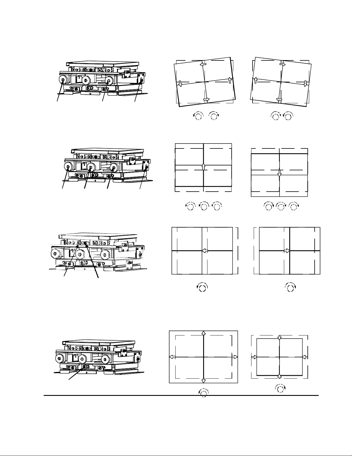
4) Picture rotation adjustment
Make loose of (J) screw and rotate the screw (A) and (B) to the same amount but the opposite
direction so that picture rotation can be changed. If rotated to the same direction Vertical
position will change. Tighten (J) after the adjustment.
(A) (B)
5) Vertical position adjustment
(J)
A B
Make loose the (J) screw and rotate (A) (B) (C) screws for the same amount, vertical position
adjustment could be done. Tighten (J) after the adjustment.
6) Horizontal position adjustment
(A) (B)
(C)
(J)
A CCAB
Loosen screw (E) and adjust (D) screw for horizontal position. Tighten (E) after the adjustment.
7) Image size adjustment
(D)
(E)
D D
Rotate (F) screw so that entire table will move to front or back. Placing the adjustment table far
from the screen will make the picture size bigger and closer the table will result the size sm aller.
Adjust the size to the point that 2 pixels will be hidden by mullion. The outside line of the internal
test signal will appear for 6 pixels thickness in the image.
Do not adjust this if mechanism comes to an end, further adjustment will damage the mechanism.
(F)
F
ADJUSTMENT
Above adjustments will do positioning and also sizing. The position could be compensated by the
electronic adjustment but the size needs to be done mechanically. It is better to make mechanical
adjustment as much as possible so that any different magnification, the image will appear right.
25
BA
B
F
Page 26

8) Upper portion Pin-cushion adjustment
This adjustment is to bent the mirror and make the adjustment, do not over do it.
This adjustment is easy to do while cube is not assembled to wall but even assembled, it is possible
to perform removing the screen of the cube, attached on it.
Important Notice:
Do not exceed the adjustment too much, when mechanism comes to an end of its adjustment area,
there is no stopper mechanism provided and further forcing to do so will make fatal damage to the
mechanism.
These mechanical adjustments are important to display all the light coming out from engine to
the full screen. If this mechanism adjustment is not good, picture may not appear in full screen
however by electronic position and capture may possible to display.
Still, the 1st adjustment to obtain the full image is not an electronics but mechanism.
After performing all the mechanical adjustments, then electronic adjustment could be started.
Here is the summary of the adjustments.
1. Mechanical position adjustment by internal or external flat-field picture. Before this adjustment,
it is better to reset all the electronic position adjustments at the center/reset value.
2. Electronic Picture Position adjustment by external signal, there may be a little differences between
internal and external signal positions so that the signal which is generated from the PC which will
be used, is the best to supply.
3. After the position adjustments, then, color balance adjustment would be performed.
DMD drive condition can be changed by “Cutoff” and “Drive”. These adjustments could be
Done by internal test signal.
Then, “Offset” and “Gain” are provided to compensate the difference of signal level from PC.
3. Electronics Adjustment or Setting
Selection or adjustment can be performed using optional Remote Control, model CT-90000 or no
Ob ligation, user-risk freeware, “Cube Commander”.
Not all keys are used for adjustment.
Connect the remote control to the REMOTE jack (3.5mm stereo jack) on the projector.
26
Page 27

This chart is indicating the
This remote control is compatible for most of Toshiba data -wall display cube.
The GUI of cube commander is also similar layout of the push buttons so that once the position of
these key pads are getting familiar, both can be used without any difficulty.
Difference between this remote control and software is, the ID number access, this is caused by the
command generation CPU, in a PC which the software is installed or use the CPU in the cube.
stand-by mode ßà normal mode ßà adjust mode ßà special mode
Power Power Cut -off 1: Auto-Adj on-off
Digital Drive 7: Picture in Picture
Video1 Gain 8, A, B, C: OSD color
RGB1 Off-set 9: Power Delay time
ID mode RGB2 Contrast D: Firmware Version
ID.ALL White Balance Brightness E: Lamp Timer History
ID.SEL Adjust Color F: Current Lamp timer
ID.SET Call Tint
ID.CLR STD Sharpness
Adjust * MODE (0-9) Phase ßà service mode
(Mag. Memory) Clock 0:
Capture 1: OSD Mute
Magnification 2: Screen mode Lock
Layout 4: Picture smoothing filter
Position C:
Test pattern
Mode
Flip
Call
functions and also which button
7: Color Mix (color coordinate) 4=R, 5=G, 6=B
can be selected.
* MODE button makes to recall
Magnification memorized at
0-9 memory positions (ref P36)
ADJUSTMENT
3-1. Input Signal selectio n
Sources are selected by pressing the relevant source button: RGB1 RGB2 or VIDEO.
To select and display video picture, the video input adaptor need to be installed.
The screen will mute for approximately 5-7 seconds following source selection.
Source sele ction is basically possible in Normal Mode.
27
Page 28

3-2. Adjust Mode
Press ADJUST to enter Adjust Mode.
To exit Adjust Mode press ADJUST twice (one press will request confirmation that
you wish to exit Adjust Mode).
3-3. Saving adjustments
Adjusted value will be memorized into its non -volatile memory when WRITE button is clicked.
In case if the new adjustment value is not acceptable, simply shut off the power by rocker switch
so that this new adjusted value will be erased and go back to “before adjustment” value.
3-4. Adjustment parameters
All parameters except ‘Layout’ can be adjusted using the ? ? ? ? buttons.
‘Layout’ position is adjusted using the ´ ` < > buttons.
3-5. Internal Test Pattern
Test Patterns can be accessed by pressing TEST.P in Adjust Mode.
Continuously pressing TEST.P button will cycle through the available patterns or individual
patterns can be selected by entering the relevant two digits number as 0 7 TEST.P for direct
number access for test signal #7.
3-6. White Balance adjustment
There are three independent memories for white balance adjustments, press WB in NORMAL mode
to select the desired memory (WB1, WB2 or WB3) before making adjustments.
There are two stages for white balance or color balance adjustment to allow adjustment of
low-signal-level and high-signal-level portions of the image.
For low-signal level adjustment, 10-20% IRE signal is required and this should be provided by
the signal source to be used (i.e. if video is the source, a video test pattern generator should be
used and if computer is the main source, test pattern generating software should be used).
BRIGHTNESS will control the overall brightness of the image and CUTOFF then followed by
ADJ.R, ADJ.G and ADJ.B can be used to adjust the relative intensities of red, green and
blue.
For high-signal level adjustment, around 70-80 -90% IRE signal is required.
CONTRAST will control the overall level of the image and DRIVE followed by ADJ.R, ADJ.G and
ADJ.B can be used to adjust the relative intensities of red, green and blue.
3-7. Gain and Offset
The previous adjustments as cutoff, drive, contrast or brightness act on the digital signal
(after the A/D converter) and assume a signal level of 0.7V p -p was supplied.
It is also possible to adjust the analogue signal (before the A/D converter) but these
adjustments should be kept to the default values in most cases of connecting one PC.
While DVI connection is used, this adjustment is not available.
ADJUSTMENT
In case if the display is connected to multiple output card or such equipment having several
individual outputs as video-wall processor, offset/gain adjustments w ill be the right an basic
adjustment to compensate each signal level difference from each outputs.
OFFSET then following by ADJ.R, ADJ.G and ADJ.B can be used for the low-signal-level
adjustment and GAIN , then ADJ.R , ADJ.G and ADJ.B for the high-level adjustment.
Adjustment hint: Cutoff and Drive adjustments can be done using internal test signal.
28
Page 29

Display flat field test signal and press “cutoff” or “drive”, then adjustment is possible.
In case of “offset” and “Gain” adjustments are placed at early signal process area and internal test
signal is generated later stage than this adjustment, thus flat field test signal needs to generate
from PC. Thus PC needs to have such signal generation software installed.
These color balance adjustments need to repeat several times from low signal level,
Then perform high signal level, again, returning back to low, then high level signal.
Repeat them several times to achieve better color balance.
This is the general idea of adjustments:
DVI input: only “Cutoff” and “Drive” by internal test signal or from PC
RGB1 or RGB2, one PC: “Cutoff” “Drive” by internal test signal or signal from PC and then, also
“Offset” “Gain” by signal from PC for sub-adjustment
RGB1 or RGB2 using video-wall processor: “Cutoff” “Drive” by internal test signal and “Offset”
“Gain” by the test signal comes from PC
In this case, Offset and Gain adjustments are much more important to
perform.
Video input: “Cutoff” “Drive” by internal test signal and possibly “Brightness” and
“Contrast” if needed by the signal from source
3-8. Clock frequency adjustment and phase adjustment
Supply fine pitch signal (such as Windows shut -down screen) and adjust CLOCK and PHASE
to eliminate moiré an d jitter.
3-9. Image position adjustment
Initial image position should be adjusted using the mechanical adjustments with internal test picture
while electronic positions are at center so that all the unmagnified images appear at the same
position. Use POSI to electronically shift the image and CAP to select the position of the image for
magnification.
3-10. Screen Mode (frequency) Selection
Incoming signals are automatically synchronized and the relevant timing data is stored in memory so that
this data can be read out each time a particular source is recognized. RGB1 and RGB2 settings are
memorized separately. There are total of 10 signal memory areas available, additional frequencies differ
from VESA standard, they will be memorized for next time synchronization.
3-11. On-Screen-Display, OSD
The default condition is for the OSD to be on, this can be switched off by pressing the CALL button in
Adjust Mode.
ADJUSTMENT
It is possible to change the color of the OSD:
SPECIAL A = red, SPECIAL B = green, SPECIAL C = blue, SPECIAL 8 = white.
3-12. Video Enhancer
When video input is selected, the following adjustments are available: COLOR , TINT (NTSC only)
and SHARP
3-13. Picture in Picture
This is a feature which opens a small window and insert video image. The video signal input
Terminal adaptor need to place. The PC image is the base and small window has video signal
29
Page 30

Image, they cannot be changed. Get into Special mode by SPECIAL and 7 buttons will guide
to this feature. PIP picture position can be changed by arrow keys.
3-14. Image Orientation
The image orientation can be flipped up, down, left and right using the FLIP key.
3-15. Status Indication
Pressing CALL in Normal Mode will display general information such as input selection and source
frequency.
Pressing SPECIAL and then D in Adjust Mode will display software version and date.
SPECIAL F will display the lamp timer and SPECIA L E will display lamp history.
3-16. Factory reset STD key
This key need to be careful since all the adjustment data will be reset if pushed.
There is an on-screen-display indicating if this function would be performed or not.
Pressing this button again will erase all the adjustments and data are reset.
3-17. Color Mix adjustment (Color coordinate Control)
This is to compensate the color difference for example, when red picture is displayed on multiple
screens and reds are different as pure red vs orange red. An ideal condition is to have all the same
pure red all over the screens but in case if orange-red appeared at once cube, then other cube can be
color compensated to add some greens so that other red can be matched to the orange-red so that all
the colors can be matched same. Opposite operation, making orange to red is impossible.
Use 7 button while in Adjust mode, then click 4 for Red primary color and select ADJ.G for
the color to be mixed in case of above situation. The prima ry color would be 5 for Green, 6 for Blue
and ADJ.R , ADJ.G or ADJ.B will select the color to be mixed.
4. Multiple Screen Wall system (example)
The picture shows 2x2 wall by one PC displaying picture,
using internal magnification capability.
To make this image by internal signal processor, MAG
need to be set to 2x2 and left top cube need to have
Layout of 1 -1. The cube at right bottom needs to have
Layout of 2 -2. Small position adjustment may be needed
to match the picture. When using internal magnification
capability, still, all the cubes need to receive the same signal
and DVI digital link will cover this part, using DVI cables.
When cube need to control or any adjustment needed, then each cube need to have its ID #
different from the others so that the command can be sent to the right ID # cube.
This picture effect (ex. 2x2) can be memorized as User Magnification Pattern (p -36).
ADJUSTMENT
5. ID Assignment (example)
IDs should be assigned before connecting the RS232C control link cables and if ID has assigned
already and want to change, it must be cleared at first befo re they can be re-assigned.
5-1. Clearing I.D.
Press ADJUST to enter Adjust Mode and then press ID.ALL to enter I.D. Mode, press ID.SEL
3 times and then press ID.CLR to erase the current I.D.
5-2. Setting I.D.
Press ID.ALL so that ‘INPUT ID NUMBER’ appears and enter the desired 2 digits I.D. using the
alpha-numeric keys. Press ID.SEL 3 times and then ID.SET to assign the I.D. – the OSD will
disappear and the unit will return to Normal Mode.
30
Page 31

5-3 Selecting I.D.
If using Cube Commander software simply select the two digits I.D. for the cube you wish to control.
If using remote control it is necessary to press ID.SEL to access the correct menu for I.D. selection
and control.
If ID.ALL is pressed instead of an alpha-numeric key ‘X’ will appear, pressing ID.ALL twice will
display ‘XX’ (two wild cards) which will allow to control of all units simultaneously.
6. Magnification
To magnify the image, press MAG in Adjust Mode to change the magnification factor then type H+V
magnification numbers as needed such as 1x1, 2x2… It is also possible to select the magnification
factor for uneven magnification as 4x3 for example, horizontal of x4 and vertical of x3 magnification.
To make this magnification effective, MAG needs to be clicked again.
Once the desired magnification has been selected press LAYOUT followed by ´ ` < > to select
the portion of the image to be displayed. If the picture will not match at the mullion area, then
POSI. will cover the adjustment. Then, to memorize this picture, press WRITE .
7. Function in Special mode
7-1. Auto-Adjust On-Off
This is to select if automatic centering function, of frequency converter, necessary or not.
Auto center may have a chance to shift the image when power is completely down and on again.
7-2. Picture in Picture
By using 7 key after entering Special mode, Picture in Picture is possible. Always, the base picture
is PC signal supplied to RGB input and small window picture is the signal supplied to Video input,
composite signal.
7-3. OSD color
On screen display color can be changed by 8 : wh ite, A : red, B : green or C : blue in
Special mode.
7-4. Power On delay
By the setting of small power on timing to avoid the same time of lamp trigger, power supply can
be set from 0-sec to 4.5-sec. This delay time is not accurate since the lamp may not ignite by the
1st trigger all the time. Entering SPECIAL mode, then click 9 makes to change the Delay time.
7-5. Firmware version
Using D button in Special mode, the system Firm-ware version could be displayed.
ADJUSTMENT
7-6. Lamp Timer History
By E button, Lamp usage timer history could be displayed.
7-7. Current Lamp Timer indication
This mode will display only one lamp display, the current lamp. When lamp timer needs to reset,
Entering to this mode will conduct to the further operation.
7-8. Lamp Timer Reset
While in Special mode, F will indicate the current lamp timer and using STD button twice,
then WRITE button, the current timer count will stop and starts from new counter reading.
8. Function in Service mode
8-1. OSD Mute
This is similar as like as CALL button clicked while in Adjust mode, OSD would be erased or
displayed on the screen by 1 button while in Service mode. Even when OSD is erased, still the
31
Page 32

function is continue to operate as in the same operation mode. One of the good way to use this
operation is, in normal condition, OSD appears when Input is selected in Normal mode. Some user
may not like this, then enter this mode or other method is, enter Adjust mode, then click CALL so
that OSD will disappear even in the system is in Adjust mode. Then click WRITE button to
memorize this function.
8-2. Screen mode Lock
This could be used only when one designated PC used, so that the same PC picture will appear always
correct but not for the other PC. Use 2 button while in Service mode
8-3. Picture smoothing filter
This is applying smoothing filtering on picture, by using 4 button, selection can be done.
Electronic Circuit Explanation
1. Input/Output/Control PCB
RGB Input signals are switched inside of AD converter and then level controlled by Offset and
Gain, in AD9888, then fed to AD converter section of the same IC.
VIDEO input is decoded by VPC3230D, auto -switching between PAL and NTSC, the output is
supplied by 8:4:4, 16 bit digital YUV signal to PW166 frequency converter scaler (scale up/down).
DIGITAL signal is supplied to SII161, single link DVI receiver then fed to PW166.
Supplied signal to PW166 is changed to 1024x768, 60Hz and then be supplied to next stage.
Switched digital signal is supplied to SII160 to form DVI output.
The functions of PW166 scaler (scale up/down) IC are:
- Auto -detect RGB signal display timing
- Auto-adjust capture, position, signal clock and phase
- Auto -capture NTSC/PAL video signal
- Image scaling up/down (VGA, SVGA, XGA, SXGA to XGA , 60Hz)
- Frame rate conversion with frame buffer memory
- Video RGB color space conversion
- Test pattern OSD generation
- On-chip 16 bit MPU for software development
- DMD control signal Generation
- Digital 24-bit RGB, XGA outputs
-
ELECTRIC CIRCUIT EXPLANATION
Incoming signals are all converted to XVGA, 60Hz except PAL signal (50Hz).
Signal recognition and scaling is carried out using standard VESA signals, if a non-standard signal is
supplied, the image may not be displayed correctly.
All incoming signals are converted to 60Hz and the color filter wheel rotation speed is 120Hz.
The output from the scaler is supplied to GmZ4S magnification IC and then, sent to DMD drive board.
2. DMD Driver PCB
The processed digital signal is sent from the RGB/Control PCB to the DMD Driver PCB via multiple
pins connector (50-pin & 30-pin) together with all the necessary signal and also power supply.
The TI driver IC, DDP1000 controls the signal, supplies to the DMD through frame memory buffers,
also color wheel motor signal is sent to M307982APZ.
The DMD element, TI Driver DDP1000 and DAD1000 form DDR chip set, a Texas Instruments
products.
Signal send out timing from TI driver to DMD is programmed to suit Toshiba filter wheel which is
based on good color reproduction even having white portion for so called “non-flicker” ignition.
32
Page 33

The lamp used is UHP 100/120W, driven by the ballast, this lamp/ballast combination is made by
Philips enables to select lamp power for 100W or 120W by mechanical slide switch.
Do not replace the lamp with other model, a reflector which focuses the lamp beam is designed for
DLP use, with light tunnel application. Different lamp may not have right specification or lamp life
may be much different. The lamp for previous model, P500DL, is different from the P503DL lamp.
To avoid such confusion, the lamp connector has different shape so that other lamp will not fit.
3. Power Supply PCB
The power supply consists of two sections, Power Factor Control and DC-DC conversion.
Incoming AC is rectified and supplied to the PFC converter, where the voltage and current phases are
matched, thus resulting power factor becomes 1.
The output of the PFC circuit is 380V DC and this is supplied to the main DC-DC converters and also
the Lamp Ballast.
The outputs of the main DC-DC converter are +12V, +6V and +4.5V.
Also, +12V which is connected to the fans and +5V for micro processor are separately prepared.
4. Lamp Ballast PCB
The Philips® 100/120W UHP lamp is driven by Philips ballast, power supply. The input voltage is
380V DC and high voltage trigger which is about 20kV pulse to i gnite while lamp start period and
lamp supply voltage is given to continue to its discharge by about AC50V, plus non-flicker pulse drive
voltage is superimposed from lamp ballast output.
5. RS232C Control PCB
RS232C control signal or/and remote control from optional CT90000 are accepted, if both are
connected CT90000 has priority over RS232C communication line.
RS232C parallel cables need to use.
6. Video PCB (option)
Accepts PAL/NTSC/SECAM composite video signal and has a buffered output for loop-through.
Normally in case of PC picture, DVI internal link would be used for not so much active movement
pictures but in case of video picture, sometimes, DVI link may contain some picture frames of delay
occurred by each cubes so that images of all the cubes may not match but later the connection,
more movement delays may result.
In such occasion, Video output to next video input, video loop through may results better picture
by less delay composed.
Appendix-1
P503DL control board LED status
POWER FAN LAMP Blink time
POWER OFF
STANBY
Preparation
POWER ON
FAN STOP
LAMP cannot
light
OFF OFF OFF
ON (red) OFF OFF
ON (green) ON (green) OFF Before Lamp lights
ON (green) ON (green) ON (green) After Lamp lights up
ON (green) ON (green) ON (green) Normal
ON (green) Blink
(green)
ON (green) ON (green) OFF
OFF 0.2 SEC Lamp will shutdown
33
Page 34

LAMP Broken ON (green) ON (green) Blink
(green)
Interlock ON (green) ON (green) Blink
(green)
FAN NG ON (green) Blink
(green)
Normal
Preparation
STAND-BY
ON (green) ON (green) ON (green)
Blink (red) ON (green) OFF 0.5 SEC Lamp shutdown
ON (red) OFF OFF STANBY
OFF 0.2 SEC Before light the Lamp
0.2 SEC
0.5 SEC
Note:
1. When power switch is turned ON, 2 LEDs, POWER and FAN will turn ON.
2. After lamp is safely turned on, then LAMP LED turns ON.
3. When display is turned off by remote control or operation software, this display will enter to STAND-BY
mode, having all the power supplied to the circuit but for the lamp and motors and POWER LED turns
ON by red color, no Fan/Lamp LEDs light.
4. When main locker power switch is shut off, all the power will be off (full reset).
5. When any Fan had a difficulty and stop rotation, FAN LED starts to blink.
6. When lamp has difficulty and did not turn on, LAMP LED blinks.
Once the display entered to STAND -BY mode, this can be confirmed by red POWER LED turns ON, in this
condition, turning ON-OFF of main power will not restart the set.
This should be operated by the remote control or the software and hit POWER button on the remote control
or software GUI after main locker switch is turned on and confirm that the red LED is lit, then click POWER
button so that display will turn ON and power LED indicator changes to Green.
When main power is disconnected or power failure occurred during its operation, the equipment will turn ON when
power is restored.
34
Page 35

Overall block diagram
Note: DVI signal Link output
is converted to XGA/60 signal
Note:
1. RS232C is connected to PW166B Scaler
2. Lamp ballast is using reduced flicker ignition system, use specified lamp listed in the parts list
Note: When color balance adjustment is necessary, this is a small hint to perform.
1. Use internal test signal so that flat field is displayed to all the displays.
2. Offset/Gain cannot be performed since these adjustments are located before the test signal generator
section.
3. Supply low signal level about 10 or 20% amplitude and adjust “CUTOFF” of each displays and obtain
the same white balance.
4. Supply high level signal about 70-80-90% whichever suite to the occasion.
Adjust “DRIVE” so that all the displays have the same white balance.
5. Repeat Cutoff/Drive adjustments several times since each adjustments affect each other.
6. When a magnification/picture-insertion signal processor is used, connect each output wire to each
display.
7. Adjust “OFFSET/GAIN” so that all the colors/white balances are the same. This is to compensate
the difference of output signal level of each input, do not touch or readjust Cutoff/Drive, these
adjustments are done in previous stage.
8. When RGB signal distribution amplifier/buffer is used and each signals are connected to each
displays, follow the same way to adjust the Cutoff and Drive by one signal source and compensate by
Offset/Gain for each signal level differences.
35
Page 36

Appendix-2
Control via RS-232C – Command Protocol list
Table –1 RS -232C pin-connection configuration
Pin No Signal name Signal items I/O (in projector)
1 CD Not used 2 RXD Reception data Output
3 TXD Transmission data Input
4 DTR* Data terminal ready Input
5 SG Signal ground Ground
6 DSR* Data set ready Output
7 RTS** Transmission request Input
8 CTS** Transmission enable Output
9 CI Not used -
* Shorted at projector inside ** Shorted at projector inside
Table –2 RS -232C Communication status
Status name Status
Communication system Transmission speed : 9600 bps
Parity bit : NO, Data length : 8 bit, Stop bit : 1 bit
Communication type 1 Block consists of STX (1Byte) + IDT(2Byte) + CMD (3Byte) + ETX (1Byte).
STX=02h, ETX=03h, IDT= Alphanumeric character (0-9, A -F, *)
2-2-3 Control Commands List:
Table : 1 Standby mode (Command to be used in standby mode )
Item Contents Key(CMD**)
POWER Turning power ON PWR PON
PWR: Alternation switch command PON: Direct switch command
Table : 2 Normal mode (Command to be used in normal mode )
Item Contents Key(CMD**)
POWER Switch projector on-off, Enter stand-by or escape PWR POF PON
CALL Show status on the screen, on-off DSP DON DOF
RGB1 Selects RGB – 1 input source IN1
RGB2 Selects RGB – 2 input source IN2
DIGITAL Selects DIGITAL Link input source IN3
VIDEO Selects VIDEO input source IN4
W/B Switch white balance mode (W/B 1.2.3) WBL WB1 WB2 WB3
ADJUST Enters adjustment mode (ADJUST Mode) AJS AJY
ID SET Setting ID IDS
ID SEL ID Selection IDT
Mute Picture mute on-off MSW MON MOF
STD Reset user setting to factory defaults VST
MODE+0 User magnification pattern 0 SM0
MODE+1 User magnification pattern 1 SM1
MODE+2 User magnification pattern 2 SM2
MODE+3 User magnification pattern 3 SM3
MODE+4 User magnification pattern 4 SM4
MODE+5 User magnification pattern 5 SM5
MODE+6 User magnification pattern 6 SM6
MODE+7 User magnification pattern 7 SM7
MODE+8 User magnificatio n pattern 8 SM8
MODE+9 User magnification pattern 9 SM9
A + A Show 10-User sets, can be assign to custom set VNA
B + B Show custom settings, 9-sets VNB
Apply 1 Apply custom setting 1 CS1
Apply 2 Apply custom setting 2 CS2
Apply 3 Apply custom setting 3 CS3
36
Page 37

Apply 4 Apply custom setting 4 CS4
Changes layout leftward (uses in LAYOUT selection
rd (uses in LAYOUT selection
Apply 5 Apply custom setting 5 CS5
Apply 6 Apply custom setting 6 CS6
Apply 7 Apply custom setting 7 CS7
Apply 8 Apply custom setting 8 CS8
Apply 9 Apply custom setting 9 CS9
Table : 3 ADJUST MODE (Command to be used in ADJUST MODE)
Item Contents Key(CMD**)
CONT. Selects contrast adjustment ( ADC RGB gains ) CNT
BRIGHT Selects brightness adjustment ( ADC RGB offset) BRT
COLOR Selects color adjustment ( Video decoder ) COL
TINT Selects tint adjustment ( Video decoder ) TNT
SHARP Selects picture sharpness adjustment ( video decoder) SHP
CUTOFF Selects DLP low level adjustment (white balance Dark) LOW
DRIVE Selects DLP contrast adjustment (white balance High) HIG
GAIN Selects gain adjustment ( RGB separate Gain ) GAN
OFFSET Selects offset adjustment ( RGB separate Offset ) OFS
FLIP Switch image direction (1.2.3.4) FLP
POSI. Selects display position pixel base adjustment POS
CLOCK Selects sampling clock frequency adjustment CLK
PHASE Selects sampling clock phase adjustment PHS
CAP. Selects caption position adjustment mode CAP
MAG. Switches screen magnification (1x1 - 6x6 ) MAG
LAYOUT Selects screen layout selection mode LAY
TEST.P Selects internal test pattern TSP
ADJ.R Selects adjustment color Red SLR
ADJ.G Selects adjustment color Green SLG
ADJ.B Selects adjustment color Blue SLB
ADJ.RGB Selects adjustment color Red +Green + Blue SLA
Adjusts movement to up or data value increase VUP
Adjusts movement to down or data value decrease VDW
Adjusts movement to left VLF
Adjusts movement to right VRG
Change layer upward (uses in LAYOUT mode)
or test pattern number decrease (uses in TEST. mode)
Change layer downward (uses in LAYOUT mode)
or test pattern number increase (uses in TEST. mode)
mode )
Changes layout rightwa
mode )
CALL On screen display status or menu on or off DSP DOD DOF
WRITE Memorizing adjusted data VWR
SERVICE Entering SERVICE MODE SVC
SPECIAL Entering SPECIAL MODE SPC
ID.ALL Entering ID MODE IDA
ADJUST Exits ADJUST MODE (return to normal mode ) AJS AJN
MODE Enable INPUT SOURCE SWITCH in ADJUST mode MOD
AutoAdjust Execute Auto -adjust at frequency converter AUT
SPEED Select Baud Rate SPD
0 Input 0 VN0
1 Input 1 or Flip 01 VN1
2 Input 2 or Flip 02 VN2
3 Input 3 or Flip 03 VN3
4 Input 4 or Flip 04 or Color mix Primary Red VN4
5 Input 5 or Color mix Primary Green VN5
6 Input 6 or Color mix Primary Blue VN6
7 Input 7 or Color mix on-off VN7
8 Input 8 VN8
9 Input 9 VN9
DUP
DDW
DLF
DRG
37
Page 38

Table 4 : SERVICE MODE (Command to be in SERVICE MODE )
Item Contents Key(CMD**)
0
0 + 1-9
1 Switches OSD mute on or off VN1
2 Screen Mode Lock
3 Freeze on or off VN3
4 Interpolation Filter selection A-B-C-D-E VN4
5 Aspect ratio switch 4:3 or 16:9 VN5
WRITE Memories adjusted data VWR
CALL ON screen menu on or off DSP DON DOF
ADJUST Exits SERVICE MODE (return to ADJUST MODE ) AJS AJY
User picture effect Memory
User Memory read out
Show or update Mag pattern 1-9
Switching force timing
0: no force timing
A: force timing A
B: force timing B
C: force timing C
D: force timing D
E: force timing E
VN0
VN2
Table 5 : SPECIAL MODE (Command to be used in SPECIAL MODE )
Item Contents Key(CMD**)
1 Auto -adjust, on-off RA1 VN1
2 Last timing forced lock, on-off RA2 VN2
3 Frame lock on-off at SEGA60/Tri-F60 or V.S.X@60Hz RA3 VN3
4 Firmware version indication RA4 VN4
6 EEPROM reset time indication RA6 VN6
7 PIP on-off RA7 VN7
8 OSD color change to white( default ) RA8 VN8
9 Set power on delay from 0 to 4.0 seconds RA9 VN9
A Change OSD color to red RAA VNA
B Change OSD color to green RAB VNB
C Change OSD color to blue RAC VNC
D Display Software Version RAD VND
E Display elapse time and lamp replacement history RAE VNE
F Display lamp timer RAF VNF
STD Resetting present lamp timer (uses after F, then Write) VST
WRITE Memorizes adjusted data VWR
CALL Onscreen display on or off DSP DON DOF
ADJUST Exits SPECIAL MODE (return to ADJUST MODE ) AJS AJY
Table 6 : ID MODE (Command to be used in ID MODE )
Item Contents Key(CMD**)
ID.CLR Clearing ID IDC
ID.SET Setting ID IDS
ID.ALL Input * IDA
0 Input 0 VN0
1 Input 1 VN1
2 Input 2 VN2
3 Input 3 VN3
4 Input 4 VN4
5 Input 5 VN5
6 Input 6 VN6
7 Input 7 VN7
8 Input 8 VN8
9 Input 9 VN9
A Input A VNA
B Input B VNB
C Input C VNC
D Input D VND
38
Page 39

E Input E VNE
F Input F VNF
ADJUST Exits ID MODE (return to ADJUST MODE ) AJS AJY
ID.SEL Select ID IDT
Appendix-3
Trouble shooting hints
1. When lamp does not light
a. Lamp will turn on but shut-off by itself within a short period of time
This is one of the symptom when the lamp becomes to its life end. Intensity becomes low, lamp
gap becomes wide, thus ballast power supply voltage becomes not enough to sustain the charge.
the lamp needs to replace.
b. Lamp bursts
This is another phenomenon when lamp comes to its life end. The internal pressure becomes
high and lamp breaks, lamp will not turn on, this is clearly the end of lamp life.
c. Lamp will not turn on
This is also another style of its end of life. When the gap between electrodes became wide, even high
voltage ignition will not start the lamp discharge. This is another possibility. In this case, if carefully
observed, lamp ballast will make noise while start ignition trigger is supplied, if this sound can be hear,
then ballast is most possibly OK and lamp is wrong.
2. W hen lamp does not turn on
a. There are several possibility even the lamp is new. When one of the Fan stop its rotation, the motor
sensor stop sending signal and CPU will turn of the lamp power to avoid heat going up by no airflow
inside.
b. When Color wheel motor is stopped, then motor rotation signal becomes missing, then this change also
sends to stop lamp power.
c. Lamp door open, this condition also shut off the lamp power.
3. When color becomes strange
a. Electronic circuit break down will lead for such color differ ence, key components are DMD drive
board and I/O control board. 1st trial may be exchange the Control board to try out.
b. At the time when color wheel motor may not synchronize to the incoming signal, there is a possibility to
have different color or color flicker happens. If motor makes noise, then this is most possibly motor
bearing needs oil. If motor becomes difficult to have smooth rotation, the color changes sometimes and
comes back, then repeat this color change. The motor replace needed most possibly.
4. When picture is strange and totally distorted
a. There may be a possibility that some strong noise entered and micro -processor jammed. One of the
easiest way is to shut off rear rocker power switch and wait for some period of time as one minute, then
turn it on. By waiting such time, micro-processor will totally reset and possibly restart without any
difficulty. This is caused by CPU jam by noise.
b. When some difficulty happened on reset or original program start at DMD drive circuit, the picture may
not be right or also I/O control board. Try replacing these boards one by one.
39
Page 40

5. When color wheel motor needs to replace
a. When color becomes different or will not synchronize, color wheel motor may oil or replace.
b. It may be better to remove optical engine. Then follow as below pictures show.
(1) (2)
c. When mounting the color wheel motor, take care not to touch the round glass color filter which has
Note: When Lamp door switch is tripped, power supply will shut off and lamp turns off, this is not a trouble,
Color wheel motor black plastic
cover located at the center
(3) (4)
Disconnect two wires
sharp edge, there may be a risk of hand/finger hurt. Also oil f rom finger attached on the filter may
be burn during operation by lamp heat and color or brightness may not right or possible damage of filter.
this is normal operation. Before replacing the lamp, it is recommended to turn off the rocker switch
and shut off power. The door switch is provided to prevent accidental touch while lamp is ON. Still,
the lamp may be hot after door switch activated, it is better to turn off the main power switch and wait
for some period of time as several minutes until lamp becomes safe temperature.
Plastic cover removed
Color wheel mo tor removed
40
Page 41

PARTS LIST
Location No P/N Description
A101 23429090 CABINET, P503DL CABINET K
L -Mirror Assy
S-Mirror Assy
70381150 Mirror P500DL(S)
23528376 Holder-Latch C3 -803
Back- Panel Tilt
Back- Panel Lamp
A102 SCREEN ASSY P503DL
A021 23890089 ADJUSTER, TILT TABLE
A701 23067691 CARTON, CASE
A702 23946322 PACKING, PACKING MATERIALS 1-SET
A703 23941621 PROTECTION SHEET
A704 23943008A POLYETHILENE BAG
A710 23918056 DY PACKING CASE STOPPER
A711 23974996 POLY PROPYLENE BAND
Y101 23552164 OWNER'S MANUAL, P503DL
Y102 23771092 ACCESSORIES, SCREWS
AIR Filter (P503DL)
Cable 94800815 DVI Int erconnect Cable
94800803 RS232C Cable
Component 94800804 DC Fan Assy AFB0912H-R00
94800463 AC Power Cord 120V (USA)
94800xxx AC Power Cord 240V (UK)
94800464 DDR-Wire 50-pin
94800465 DDR-Wire 30-pin
94800434 Ballast Module BT120DR
94800460 DMD Chip Module DDR -DMD 0.7
94800456 LP100DR Lamp with housing 100W pulse
94800461 DDR Light-Tunnel Rod
94800458 Color wheel Assy DDR-color wheel
Circuit Board 94800806 Power supply Module Assy
94800462 PCBA DDR Control Board Assy
94800459 PCBA DDR Driver Board Assy
95800814 PCBA Video I/O Board
94800811 PCBA RS232C Board Assy
Other CT- 90000 Wired Remote Control
41
 Loading...