

Page 1

FILE NO. 140-200119
SERVICE MANUAL
COLOR TELEVISION/
VIDEO CASSETTE RECORDER
MV20FL4C
Page 2
SERVICING NOTICES ON CHECKING
As for the places which need special attentions,
they are indicated with the labels or seals on the
cabinet, chassis and parts. Make sure to keep the
indications and notices in the operation manual.
2. AVOID AN ELECTRIC SHOCK
There is a high voltage part inside. Avoid an
electric shock while the electric current is
flowing.
3. USE THE DESIGNATED PARTS
The parts in this equipment have the specific
characters of incombustibility and withstand
voltage for safety. Therefore, the part which is
replaced should be used the part which has
the same character.
Especially as to the important parts for safety
which is indicated in the circuit diagram or the
table of parts as a mark, the designated
parts must be used.
4. PUT PARTS AND WIRES IN THE
ORIGINAL POSITION AFTER
ASSEMBLING OR WIRING
There are parts which use the insulation
material such as a tube or tape for safety, or
which are assembled in the condition that
these do not contact with the printed board.
The inside wiring is designed not to get closer
to the pyrogenic parts and high voltage parts.
Therefore, put these parts in the original
positions.
5. TAKE CARE TO DEAL WITH THE
CATHODE-RAY TUBE
In the condition that an explosion-proof cathoderay tube is set in this equipment, safety is
secured against implosion. However, when
removing it or serving from backward, it is
dangerous to give a shock. Take enough care to
deal with it.
6. AVOID AN X-RAY1. KEEP THE NOTICES
Safety is secured against an X-ray by considering about the cathode-ray tube and the high
voltage peripheral circuit, etc.
Therefore, when repairing the high voltage peripheral circuit, use the designated parts and
make sure not modify the circuit.
Repairing except indicates causes rising of high
voltage, and it emits an X-ray from the cathoderay tube.
PERFORM A SAFETY CHECK AFTER
7.
SERVICING
Confirm that the screws, parts and wiring which
were removed in order to service are put in the
original positions, or whether there are the
portions which are deteriorated around the
serviced places serviced or not. Check the
insulation between the antenna terminal or
external metal and the AC cord plug blades.
And be sure the safety of that.
(INSULATION CHECK PROCEDURE)
1.
Unplug the plug from the AC outlet.
2.
Remove the antenna terminal on TV and turn
on the TV.
3.
Insulation resistance between the cord plug
terminals and the eternal exposure metal
[Note 2] should be more than 1M ohm by
using the 500V insulation resistance meter
[Note 1].
4.
If the insulation resistance is less than 1M
ohm, the inspection repair should be
required.
[Note 1]
If you have not the 500V insulation
resistance meter, use a Tester.
[Note 2]
External exposure metal: Antenna terminal
Earphone jack
HOW TO ORDER PARTS
Please include the following informations when you order parts. (Particularly the VERSION LETTER.)
1. MODEL NUMBER and VERSION LETTER
The MODEL NUMBER can be found on the back of each product and the VERSION LETTER can be
found at the end of the SERIAL NUMBER.
2. PART NO. and DESCRIPTION
You can find it in your SERVICE MANUAL.
A1-1
Page 3

TABLE OF CONTENTS
SERVICING NOTICES ON CHECKING.....................................................................................
HOW TO ORDER PARTS ..........................................................................................................
TABLE OF CONTENTS..............................................................................................................
GENERAL SPECIFICATIONS ...................................................................................................
DISASSEMBLY INSTRUCTIONS
1. REMOVAL OF MECHANICAL PARTS AND P. C. BOARDS............................................
2. REMOVAL OF DECK PARTS ............................................................................................
3. REMOVAL OF ANODE CAP ..............................................................................................
4. REMOVAL AND INSTALLATION OF FLAT PACKAGE IC ...............................................
KEY TO ABBREVIATIONS ........................................................................................................
SERVICE MODE LIST ................................................................................................................
PREVENTIVE CHECKS AND SERVICE INTERVALS..............................................................
NOTE FOR THE REPLACING OF MEMORY IC .......................................................................
SERVICING FIXTURES AND TOOLS .......................................................................................
PREPARATION FOR SERVICING.............................................................................................
MECHANICAL ADJUSTMENTS ................................................................................................
ELECTRICAL ADJUSTMENTS..................................................................................................
BLOCK DIAGRAMS
TV ............................................................................................................................................
Y/C/AUDIO/CCD/HEAD AMP/IN/OUT ....................................................................................
MICON/POWER/OPERATION/DECK....................................................................................
HIFI .........................................................................................................................................
PRINTED CIRCUIT BOARDS
MAIN/CRT................................................................................................................................
OPERATION/DECK ................................................................................................................
SYSCON/COMB ......................................................................................................................
SCHEMATIC DIAGRAMS
Y/C/AUDIO/CCD/HEAD AMP .................................................................................................
MICON .....................................................................................................................................
POWER ...................................................................................................................................
IN/OUT .....................................................................................................................................
CHROMA/IF.............................................................................................................................
SOUND AMP ...........................................................................................................................
HIFI ..........................................................................................................................................
DIGITAL COMB FILTER .........................................................................................................
TV POWER..............................................................................................................................
DEFLECTION ..........................................................................................................................
CRT..........................................................................................................................................
OPERATION ...........................................................................................................................
DECK.......................................................................................................................................
INTERCONNECTION DIAGRAM ...............................................................................................
WAVEFORMS .............................................................................................................................
MECHANICAL EXPLODED VIEWS...........................................................................................
CHASSIS EXPLODED VIEWS ...................................................................................................
MECHANICAL REPLACEMENT PARTS LIST .........................................................................
CHASSIS REPLACEMENT PARTS LIST..................................................................................
ELECTRICAL REPLACEMENT PARTS LIST...........................................................................
A1-1
A1-1
A2-1
A3-1~A3-5
B1-1, B1-2
B2-1~B2-5
B3-1
B4-1, B4-2
C1-1, C1-2
C2-1
C3-1, C3-2
C4-1
C5-1
C5-2
D1-1~D1-4
D2-1~D2-6
E-1, E-2
E-3, E-4
E-5, E-6
E-7, E-8
F-1, F-2
F-3, F-4
F-5~F-8
G-1, G-2
G-3, G-4
G-5, G-6
G-7, G-8
G-9, G-10
G-11, G-12
G-13, G-14
G-15, G-16
G-17, G-18
G-19, G-20
G-21, G-22
G-23, G-24
G-25, G-26
G-27, G-28
H-1, H-2
I-1, I-2
I-3, I-4
J1-1
J2-1, J2-2
J3-1~J3-3
A2-1
Page 4
GENERAL SPECIFICATIONS
G-1 TV CRT CRT Size / Visual Size 20 inch / 508.0 mmV
G-2 VCR System VHS Player / Recorder
G-3 Tuning Broadcasting System US System M
G-4 Signal Video Signal Input Level 1 V p-p/75 ohm
G-5 Power Power Source AC 120V,60Hz
G-6 Regulation Safety CSA
G-7 Temperature Operation +5oC ~ +40oC
System CRT Type Flat
Color System NTSC
Speaker 2 Speaker
Sound Output MAX 1.5W + 1.5W
System Video System NTSC
Hi-Fi STEREO Yes
NTSC PB No
Deck DECK OVD-6S
Heads Video Head 4 Head
FM Audio Head 2 Head
Audio /Control Mono /Yes
Erase(Full Track Erase) Yes
Tape Rec PAL Speed NTSC SP/SLP(EP)
Play PAL -
Fast Forward / Rewind Time (Approx.) FF:4'50"/REW:2'30"
Forward/Reverse NTSC or PAL-M SP/SLP(EP) = 3x,5x / 9x,15x
Picture Search
Frame Advance 1/10
Slow Speed 1/10
System Tuner and System 1 Tuner
Receive CH Destination US(w/CATV)
Intermediate Picture(FP) 45.75MHz
Frequency Sound(FS) 41.25MHz
Preset CH
Stereo/Dual TV Sound US-ST
Tuner Sound Muting Yes
Audio Signal
(0dB=0.775Vrms)
Hi-Fi Audio Signal Dynamic Range : More than 90 dB
Power Consumption at AC 115 W at 120 V 60 Hz
Protector Power Fuse Yes
Deflection 90 degree
Magnetic Field BV/BH + 0.45 G / 0.18 G
Position Front
Size 3 Inch
Impedance 8 ohm
10%(Typical) 1.5W + 1.5W
Loading System Front
Motor 3
NTSC SP/SLP(EP)
with Cassette T-120
Tuning System F-Synth
Input Impedance VHF/UHF 75 ohm
CH Coverage
FP-FS 4.5MHz
Output Level 1 V p-p/75 ohm
S/N Ratio (Weighted) 50
Horizontal Resolution at SP Mode 220Line
Input Level
Output Level
S/N Ratio at SP (Weighted) 38
Harmonic Distortion (1KHz) 1.5 %
Frequency Response at SP 100Hz - 10kHz
at LP -
at SLP 100Hz - 4kHz
Wow And Flutter : Less than 0.01 %Wrms
Channel Separation : More than 60 dB
Harmonic Distortion : Less than 1.0 %
DC -
at DC Stand by (at AC) 5 W at 120 V 60 Hz
Per Year -
Dew Sensor
Radiation DOC
X-Radiation HWC
Storage -20oC ~ +60oC
-8dB/50Kohm
-8dB/1Kohm
2~69, 4A,A-5~A-1, A~I, J~W,W+1~W+84
No
No
A3-1
Page 5

GENERAL SPECIFICATIONS
(Symbo
)
A
g/M
g
Y
G-8 Operating Humidity Less then 80% RH
G-9 On Screen Menu Yes
G-10 OSD Language English French Spanish
G-11 Clock,Timer Calendar 1990/1/1 ~ 2081/12/31
Display Menu Type Character
G-CODE(or SHOWVIEW or PLUSCODE)No. Entry
Clock / Date Yes
CH/AV Yes
Tape Counter(Linear Counter) Yes
Tape Speed Yes
Sleep Time Yes
Stereo/Audio Output Yes
Control Volume Yes
Level Bright / Contrast / Sharpness / Color Yes
Play/Stop/FF/Rew/Rec/OTR/T-Rec/Pause/Eject/Tape In
uto Trackin
Caption / Text Yes
Index
Muting Yes
Hi-Fi Yes
Repeat Yes
Zero Return
DEW
and Timer Timer Events 8 Program/ 1 Month
Back-up One Touch Recording Max Time 5 Hours
OTPB Valid Time
Sleep Timer Max Time 120
On/Off Timer Program(On Timer / Off Timer) 1
Auto Shut Off No Signal 15
Timer Back-up (at Power Off Mode) 5
Timer Rec Set Yes
Channel Setup Yes
TV Setup Yes
Auto Repeat On/Off Yes
System Setup Yes
Commercial Advance
Movie Advance
Tint Yes
Bass/Treble/Balance Yes
Manual Tracking Yes
anual Trackin
OSD Language Setting English
TV/CATV Yes
Auto CH Memory Yes
Add/ Delete Yes
Guide CH Set
V-chip Set
On/Off Timer Set Yes
Picture Yes
Audio Yes
Sap On/Off Yes
Clock Set Yes (Calendar 12h)
Language Yes
Auto Clock On/Off Yes
Standard Time Yes
Daylight Saving Time Yes
Marking On/Off
Blueback On/Off
Playback Auto/Manual
Unmarked Tape
Go To Movie
Go To Preview
Bilingal
SAP Yes
l Mark
Step 10
No Operation
Yes
es
No
No
No
No
No
No
No
No
No
No
No
No
No
No
No
No
Min
Min
Program
Min
No
Sec
A3-2
Page 6

GENERAL SPECIFICATIONS
G-12 Remote Unit RC-DQ
Control Glow in Dark Remocon Yes
Format NEC
Custom Code 40-BFh,44-BBh
Power Source Voltage(D.C) 3V
UM size x pcs UM-4 x 2 pcs
Total Keys 44
Keys Power Yes
1 Yes
2 Yes
3 Yes
4 Yes
5 Yes
6 Yes
7 Yes
8 Yes
9 Yes
0 Yes
CH Up Yes
CH Down Yes
Volume Up Yes
Volume Down Yes
Input Select Yes
Play Yes
F.Fwd Yes
Rew Yes
Pause/Still Yes
Stop Yes
Rec/OTR Yes(2Keys)
Eject Yes
Counter Reset Yes
Speed Yes
Timer Rec Yes(2Keys)
TV Monitor
Quick View Yes
Program Yes
Slow Yes
Auto Tracking Yes
Set/Tracking+ Yes
Set/ Tracking - Yes
Menu Yes
Enter Yes
Cancel Yes
Call Yes
TV/Caption/Text Yes
Sleep Timer Yes
Muting Yes
Zero Return Yes
CM Skip Yes
Audio Select Yes
Keys
No
A3-3
Page 7
GENERAL SPECIFICATIONS
G-13 Features Auto Head Cleaning Yes
G-14 Accessories Owner's Manual Language English/French
Auto Tracking Yes
HQ (VHS Standard High Quality) Yes
Auto Power On, Auto Play, Auto Rewind, Auto Eject Yes
VIDEO PLUS+(SHOWVIEW,G-CODE)
Auto Clock Yes
Forward / Reverse Picture Search Yes
Reverse Slow
One Touch Playback
Auto CH Memory Yes
Closed Caption Yes
TV Auto Shut off Function Yes
End Call
Index Search
SQPB
CATV Yes
CM Skip(30sec x 6 Times) Yes
Comb Filter Yes
TV Monitor
Program Extend
Choke Coil
Energy Star Yes
Protect of FBT Leak Circuit Yes
Dirty Head
V-chip USA V-chip
CANADA V-chip
CM Advance
Movie Advance
w/Guarantee Card Yes
Remote Control Unit Yes
Battery Yes
UM size x pcs UM-4 x 2 pcs
Rod Antenna
Poles -
Terminal Loop Antenna
Terminal U/V Mixer
300 ohm to 75 ohm Antenna Adapter Yes
Antenna Change Plug
DC Car Cord (Center+)
AC Plug Adapter
AC Cord
AV Cord (2Pin-1Pin)
Guarantee Card
Registration Card Yes
ESP Card
Warning Sheet
Dew/AHC Caution Sheet
Quick Set-up Sheet
Circuit Diagram
Service Station List Yes
Important Safeguard
No
No
No
No
No
No
No
No
No
No
No
No
No
No
No
No
No
No
No
No
No
No
No
No
No
No
No
No
No
No
A3-4
Page 8
GENERAL SPECIFICATIONS
G-15 Interface Switch Power Yes
Indicator Power Red
Key Light up Rec/OTR
Terminals Front Video Input RCAx1
Rear Video Input RCAx1
G-16 Set Size Approx. W x D x H (mm) 574 x 483 x 514.5
G-17 Weight Net (Approx.) 26.5 kg( 58.5 lbs)
G-18 Carton Master Carton
Gift Box Yes
Drop Test Natural Dropping At
Container Stuffing(40' container) 171
G-19 Cabinet Material Cabinet Front PS 94V0 DECABROM
Play Yes
Pause/Still
System Select
One Touch Playback
Channel Up Yes
Channel Down Yes
F.FWD/Cue Yes
Eject/Stop Yes
Main Power SW
Volume Up Yes
Volume Down Yes
Rew/Rev Yes
Rec/OTR Yes
Input Select
Rec/OTR Red
T-Rec Red
On Timer
CS
One Touch Playback
Play
Audio Input RCA x 2(Stereo)
Other Terminal Head Phone(Stereo & Mono, 3.5mm)
Audio Input RCA x 2(Stereo)
Video Output RCAx1
Audio Output RCA x 2(Stereo)
Euro Scart
Diversity
Ext Speaker
DC Jack 12V(Center +)
VHF/UHF Antenna Input
AC Inlet
Gross (Approx.) 28.5 kg( 62.9 lbs)
Content -
Material -
Dimensions W x D x H(mm) -
Description of Origin -
Material DOUBLE/WHITE
Dimensions W x D x H(mm) 647 x 627 x 625
Design As per Buyer's
Description of Origin Yes
Height (cm) 31
Cabinet Rear PS 94V0 DECABROM
Jack Panel PS 94V0
F Type
No
No
No
No
No
No
No
No
No
No
No
No
No
No
No
No
1 Corner / 3 Edges / 6 Surfaces
Sets
A3-5
Page 9
DISASSEMBLY INSTRUCTIONS
1. REMOVAL OF MECHANICAL PARTS
AND P.C. BOARDS
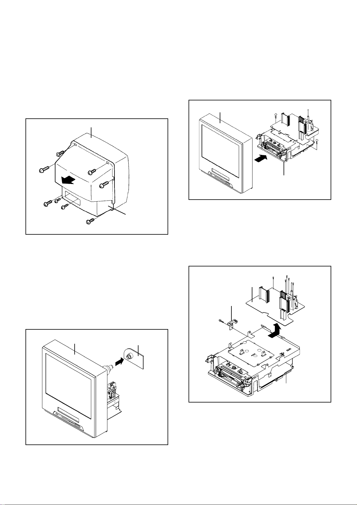
1-1: BACK CABINET (Refer to Fig. 1-1)
1.
Remove the 6 screws 1.
2.
Remove the 2 screws 2 which are used for holding the
Back Cabinet.
3.
Remove the AC cord from the AC cord hook 3.
4.
Remove the Back Cabinet in the direction of arrow.
Front Cabinet
1
1
1
1
2
2
1-2: CRT PCB (Refer to Fig. 1-2)
CAUTION: BEFORE REMOVING THE ANODE CAP,
DISCHARGE ELECTRICITY BECAUSE IT
CONTAINS HIGH VOLTAGE.
BEFORE ATTEMPTING TO REMOVE OR
REPAIR ANY PCB, UNPLUG THE POWER
CORD FROM THE AC SOURCE.
1.
Remove the Anode Cap.
(Refer to REMOVAL OF ANODE CAP)
2.
Disconnect the following connectors:
(CP801, CP802 and CP805).
3.
Remove the CRT PCB in the direction of arrow.
1
3
Back Cabinet
1
Fig. 1-1
1-3: TV/VCR BLOCK (Refer to Fig. 1-3)
1.
Remove the 2 screws 1.
2.
Disconnect the following connectors:
(CP401, CP502, CP4201 and CP4202).
3.
Unlock the support 2.
4.
Remove the TV/VCR Block in the direction of arrow.
Front Cabinet
1
TV/VCR Block
2
UP TO
RELEASE
1-4: MAIN PCB (Refer to Fig. 1-4)
1.
Remove the screw 1.
2.
Remove the Main PCB Holder.
3.
Remove the 2 screws 2.
4.
Remove the 3 screws 3.
5.
Disconnect the following connectors:
(CP810A, CP820A and CP402).
6.
Remove the Main PCB in the direction of arrow.
2
2
Main PCB
Main PCB Holder
1
3
3
3
1
Fig. 1-3
Front Cabinet
CRT PCB
VCR Block
Fig. 1-4
Fig. 1-2
B1-1
Page 10
DISASSEMBLY INSTRUCTIONS
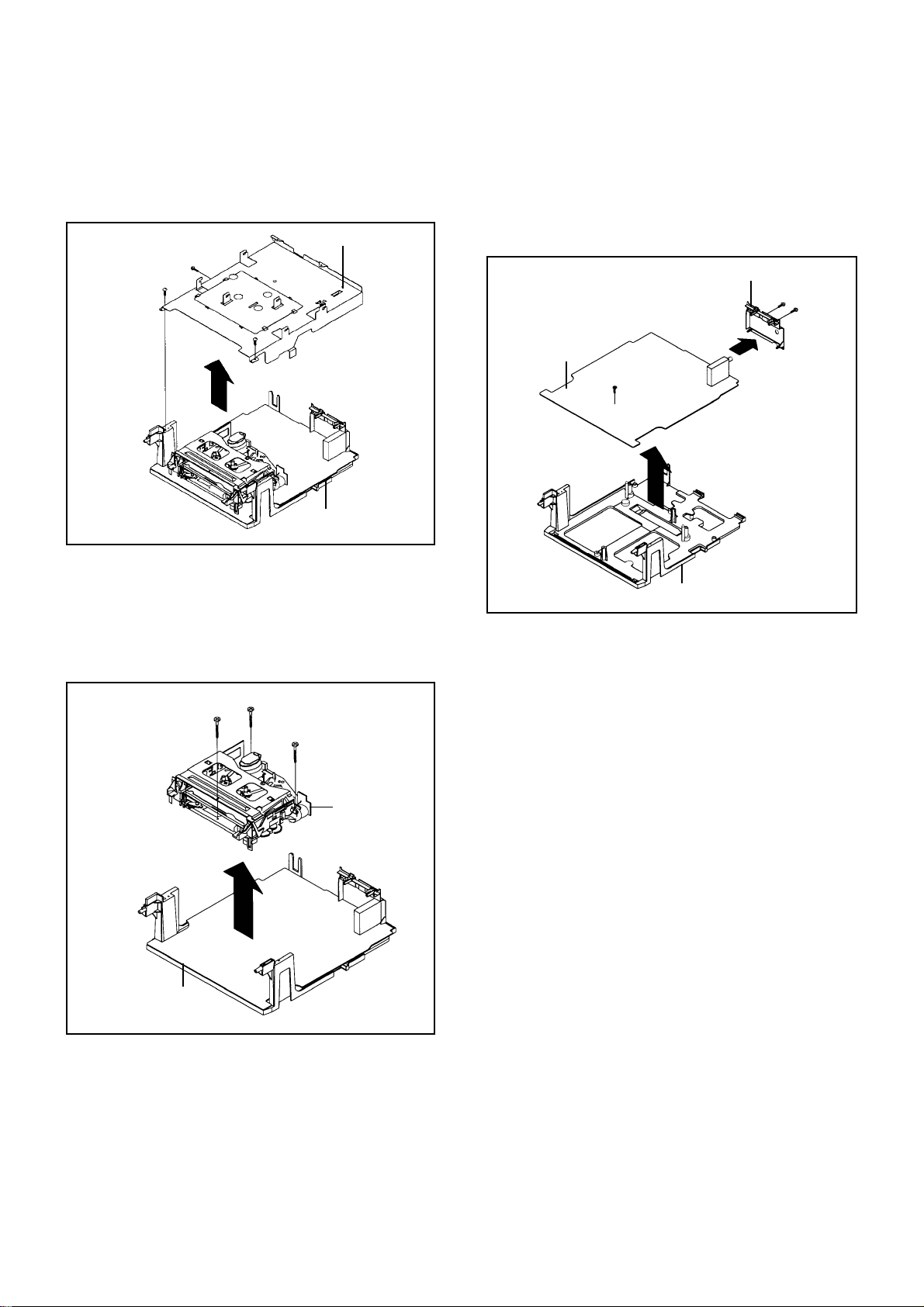
1-5: DECK SHIELD PLATE (Refer to Fig. 1-5)
Remove the 2 screws 1.
1.
Remove the screw 2.
2.
Remove the Deck Shield Plate in the direction of arrow.
3.
Deck Shield Plate
2
1
1
VCR Block
1-6: DECK CHASSIS (Refer to Fig. 1-6)
1.
Remove the 3 screws 1.
2.
Disconnect the following connectors:
(CP1004, CP1005, CP1006, CP4001, CP4002 and
CP4003).
3.
Remove the Deck Chassis in the direction of arrow.
Fig. 1-5
1-7: JACK PLATE AND SYSCON PCB (Refer to Fig. 1-7)
1.
Remove the screw 1.
2.
Remove the Syscon PCB in the direction of arrow (A).
3.
Remove the 2 screws 2.
4.
Unlock the 2 supports 3.
5.
Remove the Jack Plate in the direction of arrow (B).
Jack Plate
2
2
3
Syscon PCB
1
(A)
Deck Holder
(B)
3
Fig. 1-7
Syscon PCB
1
1
1
Deck Chassis
Fig. 1-6
B1-2
Page 11
DISASSEMBLY INSTRUCTIONS
2. REMOVAL OF DECK PARTS
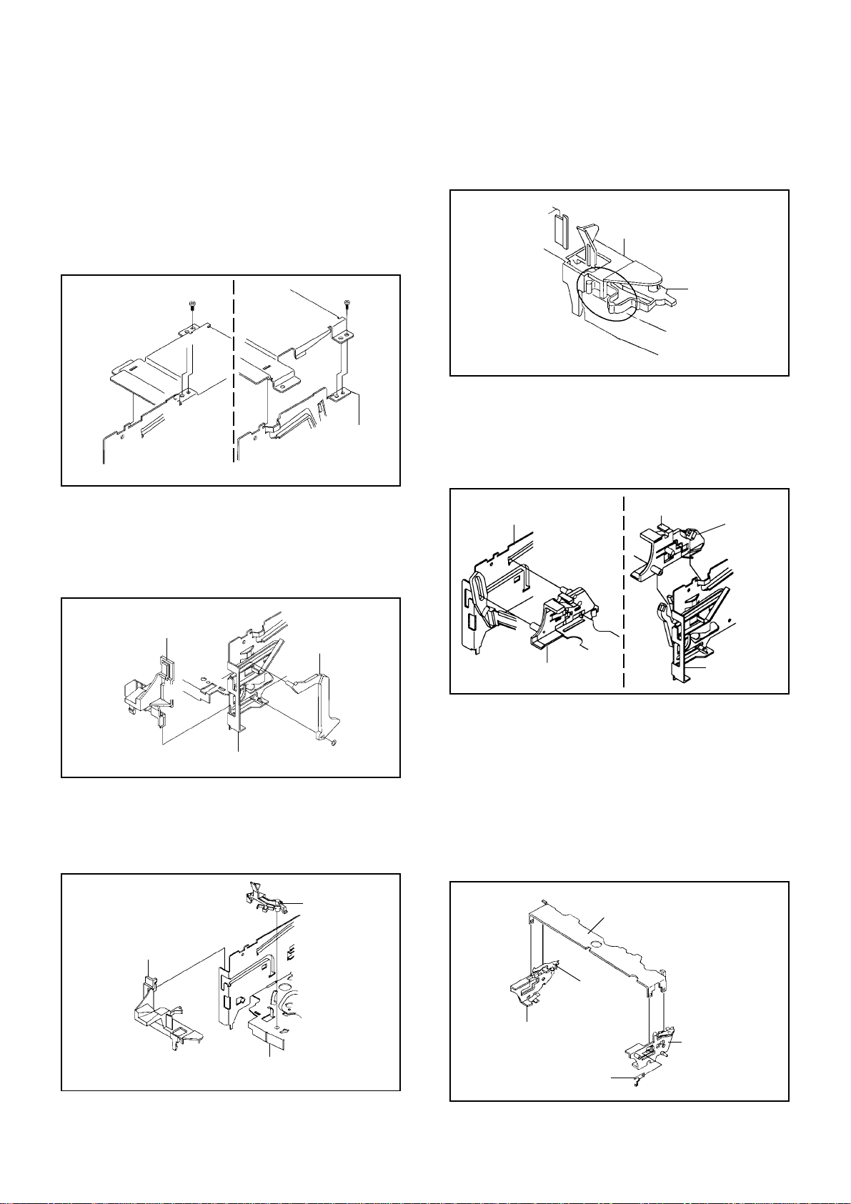
2-1: TOP BRACKET (Refer to Fig. 2-1)
Remove the 2 screws 1.
1.
Slide the 2 supports 2 and remove the Top Bracket.
2.
NOTE
When you install the Top Bracket, install the screw (1)
first, then install the screw (2).
(2)
1
Top Bracket
2
Main Chassis
• Screw Torque: 5 ± 0.5kgf•cm
Top Bracket
2
Main Chassis
2-2: FLAP LEVER/TAPE GUIDE R (Refer to Fig. 2-2)
Move the Cassette Holder Ass'y to the back side.
1.
Remove the Polyslider Washer 1.
2.
Remove the Flap Lever.
3.
Unlock the 3 supports 2 and remove the Tape Guide R.
4.
(1)
1
Fig. 2-1
NOTE
When you install the Tape Guide L, install as shown in the
circle of Fig. 2-3-B. (Refer to Fig. 2-3-B)
Tape Guide L
REC Lever
• The REC Lever is not installed on the Video Cassette Player.
Fig. 2-3-B
2-4: CASSETTE HOLDER ASS'Y (Refer to Fig. 2-4)
Move the Cassette Holder Ass'y to the front side so that
1.
the Link Ass'y doesn't slip out.
Push the Locker R to remove the Cassette Side R.
2.
Remove the Cassette Side L.
3.
Main Chassis
Cassette Side R
Locker R
Tape Guide R
Flap Lever
2
2
2
Main Chassis
1
Fig. 2-2
2-3: TAPE GUIDE L (Refer to Fig. 2-3-A)
Move the Cassette Holder Ass'y to the back side.
1.
Unlock the 2 supports 1 and remove the Tape Guide L.
2.
Remove the REC Lever. (Recorder only)
3.
REC Lever
Tape Guide L
1
1
• The REC Lever is not installed on the Video Cassette Player.
Main Chassis
Fig. 2-3-A
Cassette Side L
Main Chassis
Fig. 2-4
2-5: CASSETTE SIDE L/R (Refer to Fig. 2-5)
Unlock the 4 supports 1 and then remove the Cassette
1.
Side L/R.
Remove the Cassette Earth Spring.
2.
NOTE
1.2.When you install the Cassette Side R, be sure to move
the Locker R after installing.
After the installation of the Cassette Holder, then install
the Cassette Earth Spring.
1
1
Cassette Side R
Cassette Earth Spring
Cassette Holder
Locker R
1
1
Cassette Side L
Fig. 2-5
B2-1
Page 12

DISASSEMBLY INSTRUCTIONS
2-6: LINK UNIT (Refer to Fig. 2-6)
Set the Link Unit to the Eject position.
1.
Remove the (A) side of the Link Unit first, then remove
2.
the (B) side.
Link Unit
(B)
(A)
Main Chassis
Link Unit
Main Chassis
2-7: LOADING MOTOR ASS'Y (Refer to Fig. 2-7)
Remove the Link Lever.
1.
Remove the screw 1.
2.
Remove the Loading Motor Ass'y.
3.
Unlock the 2 supports 2 and remove the Deck PCB
4.
(BOT).
Fig. 2-6
2-9: TENSION ASS'Y (Refer to Fig. 2-9-B)
Turn the Middle Gear clockwise so that the Tension
1.
Holder hook is set to the position of Fig. 2-9-A to move
the Tension Arm Ass'y.
Remove the Tension Spring.
2.
Unlock the support 1 and remove the Tension Arm
3.
Ass'y.
Remove the Tension Adjust.
4.
Unlock the 2 supports 2 and remove the Tension Band
5.
Ass'y.
Float the hook 3 and turn it clockwise then remove the
6.
Tension Holder.
Remove the SS Brake Spring.
7.
Remove the SS Arm Brake.
8.
Tension Arm Ass'y
Fig. 2-9-A
Tension Adjust
2
2
Tension Band Ass'y
Loading Motor Ass'y
2
Main Chassis
1
Deck PCB
(BOT)
• Screw Torque: 5 ± 0.5kgf•cm
2-8: SENSOR COVER L3 (Refer to Fig. 2-8)
Unlock the support 1 and remove the Sensor Cover L3.1.
Main Chassis
Sensor Cover L3
Link Lever
Fig. 2-7
Tension Spring
SS Brake Spring
SS Arm Brake
1
3
Tension Holder
Tension Arm Ass'y
Inclined S Ass'y
Fig. 2-9-B
NOTE
When you install the Tension Adjust, install as shown in
Fig. 2-9-C. (Refer to Fig. 2-9-C)
Adjust the direction of the Marker to inside.
Fig. 2-9-C
1
Fig. 2-8
B2-2
Page 13

DISASSEMBLY INSTRUCTIONS
2-10: T BRAKE ASS'Y (Refer to Fig. 2-10)
1.2.Remove the T Brake Spring.
Turn the T Brake Ass'y clockwise and bend the hook
section to remove it.
T Brake Ass'y
Hook section
T Brake Spring
Fig. 2-10
2-11: S REEL/T REEL (Refer to Fig. 2-11)
Remove the S Reel and T Reel.
1.
Remove the 2 Polyslider Washers 1.
2.
NOTE
Take care not to damage the gears of the S Reel and T
1.
Reel.
The Polyslider Washer may be remained on the back of
2.
the reel.
Take care not to damage the shaft.
3.
Do not touch the section "A" of S Reel and T Reel. (Use
4.
gloves.) (Refer to Fig. 2-11) Do not adhere the stains
on it.
When you install the reel, clean the shaft and oil it. (If
5.
you do not oil, noise may be heard in FF/REW mode.)
After installing the reel, adjust the height of the reel.
6.
(Refer to MECHANICAL ADJUSTMENT)
S Reel
(A)
1
T Reel
(A)
1
P5 Spring
P5-3 Arm Ass'y
• Screw Torque: 5 ± 0.5kgf•cm
1
2
Cassette Opener
2
Pinch Roller Block
Pinch Roller Arm Spring
Pinch Roller Lever Ass'y
Main Chassis
Fig. 2-12-A
NOTE
Do not touch the Pinch Roller. (Use gloves.)
1.
When you install the Pinch Roller Block, install as shown
2.
in the circle of Fig. 2-12-B. (Refer to Fig. 2-12-B)
Fig. 2-12-B
2-13: A/C HEAD (Refer to Fig. 2-13-A)
Remove the screw 1.
1.
Remove the A/C Head Base.
2.
Remove the 3 screws 2.
3.
Remove the A/C Head and A/C Head Spring.
4.
NOTE
Do not touch the A/C Head. (Use gloves.)
1.
When you install the A/C Head Spring, install as shown
2.
in Fig. 2-13-B. (Refer to Fig. 2-13-B)
When you install the A/C Head, tighten the screw (1)
3.
first, then tighten the screw (2), finally tighten the screw
(3).
2-12: PINCH ROLLER BLOCK/P5-3 ARM ASS'Y
(Refer to Fig. 2-12-A)
Remove the P5 Spring.
1.
Remove the screw 1.
2.
Unlock the 2 supports 2 and remove the Cassette
3.
Opener.
Remove the Pinch Roller Block, Pinch Roller Arm
4.
Spring, Pinch Roller Lever Ass'y and P5-3 Arm Ass'y.
Fig. 2-11
B2-3
(3)
(1)
2
2
(2)
1
• Screw Torque: 5 ± 0.5kgf•cm (Screw 1)
2
A/C Head
A/C Head Spring
A/C Head Base
Fig. 2-13-A
Page 14

DISASSEMBLY INSTRUCTIONS
2-16: CAPSTAN DD UNIT (Refer to Fig. 2-16)
Remove the Capstan Belt.
1.
Remove the 3 screws 1.
2.
Remove the Capstan DD Unit.
3.
Spring Position
Fig. 2-13-B
2-14: FE HEAD (RECORDER ONLY) (Refer to Fig. 2-14)
Remove the screw 1.
1.
Remove the FE Head.
2.
FE Head
• The FE Head is not installed on the Video Cassette Player.
• Screw Torque: 4 ± 0.5kgf•cm
1
Fig. 2-14
2-15: AHC ASS'Y/CYLINDER UNIT ASS'Y
(Refer to Fig. 2-15)
Unlock the support 1 and remove the AHC Ass'y.
1.
Remove the 3 screws 2.
2.
Remove the Cylinder Unit Ass'y.
3.
NOTE
When you install the Cylinder Unit Ass'y, tighten the
screws from (1) to (3) in order while pulling the Ass'y
toward the left front direction.
AHC Ass'y
Capstan Belt
Capstan DD Unit
1
1
1
• Screw Torque: 5 ± 0.5kgf•cm
Fig. 2-16
2-17: MIDDLE GEAR/MAIN CAM (Refer to Fig. 2-17-A)
Remove the Polyslider Washer 1, then remove the
1.
Middle Gear.
Remove the E-Ring, then remove the Main Cam, P5
2.
Cam, Pinch Roller Cam and Joint Gear.
1
Middle Gear
E-Ring
Main Cam
Pinch Roller Cam
Joint Gear
P5 Cam
Cylinder Unit Ass'y
2
(2)
• Screw Torque: 3 ± 0.5kgf•cm
1
Fig. 2-17-A
NOTE
When you install the Pinch Roller Cam, P5 Cam and Main
Cam, align each marker. (Refer to Fig. 2-17-B)
Pinch Roller Cam
(1)
2
2
(3)
Check the hole of Main
Chassis can be seen.
P5 Cam
Fig. 2-15
Main Cam
Marker
Fig. 2-17-B
B2-4
Page 15

DISASSEMBLY INSTRUCTIONS
2-18: CLUTCH ASS'Y (Refer to Fig. 2-18)
Remove the Capstan Brake Spring.
1.
Remove the Polyslider Washer 1.
2.
Remove the Clutch Ass'y, Ring Spring and Coupling
3.
Gear.
Unlock the 2 supports 2 and remove the Clutch Lever.
4.
1
Clutch Ass'y
Capstan Brake Spring
Ring Spring
Coupling Gear
Clutch Lever
2
2
Fig. 2-18
2-19: LOADING GEAR S/T ASS'Y (Refer to Fig. 2-19-A)
Remove the E-Ring 1 and remove the Main Loading
1.
Gear.
Slide the Main Rod and remove the Spring Holder.
2.
Remove the Main Rod, Tension Lever, Clutch Actuator,
3.
Idler Arm Ass'y.
Remove the screw 2.
4.
Remove the LED Reflecter.
5.
Remove the Loading Arm S Ass'y and Loading Arm T
6.
Ass'y.
Remove the Loading Gear S and Loading Gear T.
7.
Remove the Loading Gear Spring.
8.
Spring Holder
1
Main Loading Gear
Tension Lever
Loading Gear T
Loading Gear
Spring
Loading Arm T Ass'y
Loading Gear S
Loading Gear
Spring
Idler Arm Ass'y
LED Reflecter
Clutch Actuator
Main Rod
2
NOTES
1. When you install the Loading Arm S Ass'y, Loading Arm
T Ass'y and Main Loading Gear, align each marker.
(Refer to Fig. 2-19-B)
Marker
Main Loading Gear
Marker
Loading Arm T Ass'y
Loading Arm S Ass'y
Fig. 2-19-B
2. When you install the Clutch Actuator, install as shown in
the circle of Fig. 2-19-C. (Refer to Fig. 2-19-C)
Clutch Actuator
Fig. 2-19-C
2-20: INCLINED S/T ASS'Y (Refer to Fig. 2-20)
Remove the Cap P4.
1.
Remove the screw 1.
2.
Unlock the support 2 and remove the Loading Gear
3.
Holder.
Remove the Inclined S Unit.
4.
Remove the Inclined T Unit.
5.
NOTE
Do not touch the roller of Guide Roller.
1
Inclined S Unit
Loading Gear Holder
2
Inclined T Unit
• Screw Torque: 5 ± 0.5kgf•cm
Loading Arm S Ass'y
Fig. 2-19-A
B2-5
• Screw Torque: 2.5 ± 0.5kgf•cm
Cap P4
Fig. 2-20
Page 16

DISASSEMBLY INSTRUCTIONS
3. REMOVAL OF ANODE CAP
Read the following NOTED items before starting work.
*
After turning the power off there might still be a potential
voltage that is very dangerous. When removing the
Anode Cap, make sure to discharge the Anode Cap's
potential voltage.
*
Do not use pliers to loosen or tighten the Anode Cap
terminal, this may cause the spring to be damaged.
REMOVAL
1. Follow the steps as follows to discharge the Anode Cap.
(Refer to Fig. 3-1.)
Connect one end of an Alligator Clip to the metal part of a
flat-blade screwdriver and the other end to ground.
While holding the plastic part of the insulated Screwdriver,
touch the support of the Anode with the tip of the
Screwdriver.
A cracking noise will be heard as the voltage is discharged.
GND on the CRT
3. After one side is removed, pull in the opposite direction to
remove the other.
NOTE
Take care not to damage the Rubber Cap.
INSTALLATION
1. Clean the spot where the cap was located with a small
amount of alcohol. (Refer to Fig. 3-3.)
Location of Anode Cap
Fig. 3-3
NOTE
Confirm that there is no dirt, dust, etc. at the spot where
the cap was located.
2.3.Arrange the wire of the Anode Cap and make sure the
wire is not twisted.
Turn over the Rubber Cap. (Refer to Fig. 3-4.)
Screwdriver
Alligator Clip
GND on the CRT
Flip up the sides of the Rubber Cap in the direction of the
2.
arrow and remove one side of the support.
(Refer to Fig. 3-2.)
Rubber Cap
CRT
Support
Support
CRT
Fig. 3-1
Fig. 3-2
Fig. 3-4
4. Insert one end of the Anode Support into the anode button,
then the other as shown in Fig. 3-5.
Support
CRT
5.6.Confirm that the Support is securely connected.
Put on the Rubber Cap without moving any parts.
Fig. 3-5
B3-1
Page 17

DISASSEMBLY INSTRUCTIONS
4.
REMOVAL AND INSTALLATION OF
FLAT PACKAGE IC
REMOVAL
Put the Masking Tape (cotton tape) around the Flat
1.
Package IC to protect other parts from any damage.
(Refer to Fig. 4-1.)
NOTE
Masking is carried out on all the parts located within
10 mm distance from IC leads.
When IC starts moving back and forth easily after
3.
desoldering completely, pickup the corner of the IC using
a tweezers and remove the IC by moving with the IC
desoldering machine. (Refer to Fig. 4-3.)
NOTE
Some ICs on the PCB are affixed with glue, so be
careful not to break or damage the foil of each IC
leads or solder lands under the IC when removing it.
Blower type IC
desoldering
machine
Masking Tape
(Cotton Tape)
Heat the IC leads using a blower type IC desoldering
2.
IC
machine. (Refer to Fig. 4-2.)
NOTE
Do not add the rotating and the back and forth
directions force on the IC, until IC can move back and
forth easily after desoldering the IC leads completely.
Blower type IC
desoldering machine
Fig. 4-1
Tweezers
IC
Peel off the Masking Tape.4.
Absorb the solder left on the pattern using the Braided
5.
Shield Wire. (Refer to Fig. 4-4.)
NOTE
Do not move the Braided Shield Wire in the vertical
direction towards the IC pattern.
Fig. 4-3
Braided Shield Wire
Soldering Iron
IC
Fig. 4-2
IC pattern
Fig. 4-4
B4-1
Page 18

DISASSEMBLY INSTRUCTIONS
INSTALLATION
Take care of the polarity of new IC and then install the
1.
new IC fitting on the printed circuit pattern. Then solder
each lead on the diagonal positions of IC temporarily.
(Refer to Fig. 4-5.)
Soldering Iron
Solder temporarily
Supply the solder from the upper position of IC leads
2.
Solder temporarily
sliding to the lower position of the IC leads.
(Refer to Fig. 4-6.)
Fig. 4-5
When bridge-soldering between terminals and/or the
4.
soldering amount are not enough, resolder using a Thintip Soldering Iron. (Refer to Fig. 4-8.)
Thin-tip Soldering Iron
IC
Fig. 4-8
Finally, confirm the soldering status on four sides of the
5.
IC using a magnifying glass.
Confirm that no abnormality is found on the soldering
position and installation position of the parts around the
IC. If some abnormality is found, correct by resoldering.
NOTE
When the IC leads are bent during soldering and/or
repairing, do not repair the bending of leads. If the
bending of leads are repaired, the pattern may be
damaged. So, be always sure to replace the IC in this
case.
Soldering IronSolder
IC
Absorb the solder left on the lead using the Braided
3.
Supply soldering
from upper position
to lower position
Shield Wire. (Refer to Fig. 4-7.)
NOTE
Do not absorb the solder to excess.
Soldering Iron
IC
Braided Shield Wire
Fig. 4-6
Fig. 4-7
B4-2
Page 19

A
A/C
ACC
AE
AFC
AFT
AFT DET
AGC
AMP
ANT
A.PB
APC
ASS'Y
AT
AUTO
A/V
B
BGP
BOT
BPF
BRAKE SOL
BUFF
B/W
C
C
CASE
CAP
CARR
CH
CLK
CLOCK (SY-SE)
COMB
CONV
CPM
CTL
CYL
CYL-M
CYL SENS
D
DATA (SY-CE)
dB
DC
DD Unit
DEMOD
DET
DEV
E
E
EF
EMPH
ENC
ENV
EOT
EQ
EXT
F
F
FBC
FE
FF
FG
FL SW
FM
FSC
FWD
G
GEN
GND
H
H.P.F
KEY TO ABBREVIATIONS
:
Audio/Control
:
Automatic Color Control
:
Audio Erase
:
Automatic Frequency Control
:
Automatic Fine Tuning
:
Automatic Fine Tuning Detect
:
Automatic Gain Control
:
Amplifier
:
Antenna
:
Audio Playback
:
Automatic Phase Control
:
Assembly
:
All Time
:
Automatic
:
Audio/Video
:
Burst Gate Pulse
:
Beginning of Tape
:
Bandpass Filter
:
Brake Solenoid
:
Buffer
:
Black and White
:
Capacitance, Collector
:
Cassette
:
Capstan
:
Carrier
:
Channel
:
Clock
:
Clock (Syscon to Servo)
:
Combination, Comb Filter
:
Converter
:
Capstan Motor
:
Control
:
Cylinder
:
Cylinder-Motor
:
Cylinder-Sensor
:
Data (Syscon to Servo)
:
Decibel
:
Direct Current
:
Direct Drive Motor Unit
:
Demodulator
:
Detector
:
Deviation
:
Emitter
:
Emitter Follower
:
Emphasis
:
Encoder
:
Envelope
:
End of Tape
:
Equalizer
:
External
:
Fuse
:
Feed Back Clamp
:
Full Erase
:
Fast Forward, Flipflop
:
Frequency Generator
:
Front Loading Switch
:
Frequency Modulation
:
Frequency Sub Carrier
:
Forward
:
Generator
:
Ground
:
High Pass Filter
H.SW
Hz
I
IC
IF
IND
INV
K
KIL
L
L
LED
LIMIT AMP
LM, LDM
LP
L.P.F
LUMI.
M
M
MAX
MINI
MIX
MM
MOD
MPX
MS SW
N
NC
NR
O
OSC
OPE
P
PB
PB CTL
PB-C
PB-Y
PCB
P. CON
PD
PG
P-P
R
R
REC
REC-C
REC-Y
REEL BRK
REEL S
REF
REG
REW
REV, RVS
RF
RMC
RY
S
S. CLK
S. COM
S. DATA
SEG
SEL
SENS
SER
SI
SIF
SO
SOL
SP
STB
SW
:
Head Switch
:
Hertz
:
Integrated Circuit
:
Intermediate Frequency
:
Indicator
:
Inverter
:
Killer
:
Left
:
Light Emitting Diode
:
Limiter Amplifier
:
Loading Motor
:
Long Play
:
Low Pass Filter
:
Luminance
:
Motor
:
Maximum
:
Minimum
:
Mixer, mixing
:
Monostable Multivibrator
:
Modulator, Modulation
:
Multiplexer, Multiplex
:
Mecha State Switch
:
Non Connection
:
Noise Reduction
:
Oscillator
:
Operation
:
Playback
:
Playback Control
:
Playback-Chrominance
:
Playback-Luminance
:
Printed Circuit Board
:
Power Control
:
Phase Detector
:
Pulse Generator
:
Peak-to Peak
:
Right
:
Recording
:
Recording-Chrominance
:
Recording-Luminance
:
Reel Brake
:
Reel Sensor
:
Reference
:
Regulated, Regulator
:
Rewind
:
Reverse
:
Radio Frequency
:
Remote Control
:
Relay
:
Serial Clock
:
Sensor Common
:
Serial Data
:
Segment
:
Select, Selector
:
Sensor
:
Search Mode
:
Serial Input
:
Sound Intermediate Frequency
:
Serial Output
:
Solenoid
:
Standard Play
:
Serial Strobe
:
Switch
C1-1
Page 20

S
SYNC
SYNC SEP
T
TR
TRAC
TRICK PB
TP
U
UNREG
V
V
VCO
VIF
VP
V.PB
VR
V.REC
VSF
VSR
VSS
V-SYNC
VT
X
X'TAL
Y
Y/C
KEY TO ABBREVIATIONS
:
Synchronization
:
Sync Separator, Separation
:
Transistor
:
Tracking
:
Trick Playback
:
Test Point
:
Unregulated
:
Volt
:
Voltage Controlled Oscillator
:
Video Intermediate Frequency
:
Vertical Pulse, Voltage Display
:
Video Playback
:
Variable Resistor
:
Video Recording
:
Visual Search Fast Forward
:
Visual Search Rewind
:
Voltage Super Source
:
Vertical-Synchronization
:
Voltage Tuning
:
Crystal
:
Luminance/Chrominance
C1-2
Page 21

SERVICE MODE LIST
This unit provided with the following SERVICE MODES so you can repair, examine and adjust easily.
To enter SERVICE MODE, unplug AC cord till lost actual clock time. Then press and hold Vol (-) button of main unit and
remocon key simultaneously.
The both pressing of set key and remote control key will not be possible if clock has been set. To reset clock, either unplug
AC cord and allow at least 5 seconds before Power On.
Set Key Remocon Key Operations
VOL. (-) MIN
VOL. (-) MIN 1
VOL. (-) MIN
VOL. (-) MIN
VOL. (-) MIN 4
VOL. (-) MIN
VOL. (-) MIN
0
2
3
5
6
Releasing of V-CHIP PASSWORD.
Initialization of the factory.
NOTE: Do not use this for the normal servicing.
Horizontal position adjustment of OSD.
NOTE: Also can be adjusted by using the Adjustment MENU.
Refer to the "ELECTRICAL ADJUSTMENT" (OSD HORIZONTAL).
Adjust the PG SHIFTER automatically.
Refer to the "ELECTRICAL ADJUSTMENT" (PG SHIFTER).
Adjust the PG SHIFTER manually.
Refer to the "ELECTRICAL ADJUSTMENT" (PG SHIFTER).
Adjusting of the Tracking to the center position.
NOTE: Also can be adjusted by pressing the ATR button for more than 2 seconds
during PLAY.
POWER ON total hours and PLAY/REC total hours are displayed on the screen.
Refer to the "PREVENTIVE CHECKS AND SERVICE INTERVALS" (CONFIRMATION
OF USING HOURS).
Can be checked of the INITIAL DATA of MEMORY IC.
Refer to the "NOTE FOR THE REPLACING OF MEMORY IC".
VOL. (-) MIN 8
VOL. (-) MIN 9
Method Operations
Press the ATR button on the
remote control for more than
2 seconds during PLAY.
Make the short circuit between
the test point of SERVICE and
the GND.
Writing of EEPROM initial data.
NOTE: Do not use this for the normal servicing.
Display of the Adjustment MENU on the screen.
Refer to the "ELECTRICAL ADJUSTMENT" (On-Screen Display Adjustment).
Adjusting of the Tracking to the center position.
Refer to the "MECHANICAL ADJUSTMENT" (GUIDE ROLLER) and "ELECTRICAL
ADJUSTMENT" (PG SHIFTER).
The EOT/BOT/Reel sensor do not work at this moment.
Refer to the "PREPARATION FOR SERVICING"
C2-1
Page 22

PREVENTIVE CHECKS AND SERVICE INTERVALS
The following standard table depends on environmental conditions and usage. Unless maintenance is properly
carried out, the following service intervals may be quite shortened as harmful effects may be had on other parts.
Also, long term storage or misuse may cause transformation and aging of rubber parts.
Time
Parts Name
Audio Control Head
Full Erase Head
(Recorder only)
Capstan Belt
Pinch Roller
Capstan DD Unit
Loading Motor
Tension Band
Capstan Shaft
Tape Running
Guide Post
Cylinder Unit
: Clean
: Replace
500
hours
1,000
hours
1,500
hours
2,000
hours
3,000
hours
Notes
Clean those parts in
contact with the tape.
Clean the rubber, and parts
which the rubber touches.
Replace when rolling
becomes abnormal.
Clean the Head
CONFIRMATION OF USING HOURS
POWER ON total hours and PLAY/REC total hours can be checked on the screen.
Total hours are displayed in 16 system of notation.
NOTE: The confirmation of using hours will not be possible if clock has been set. To reset clock, either unplug
AC cord and allow at least 5 seconds before Power On.
1.
Set the VOLUME to minimum.
2.
While holding down VOLUME button on front cabinet, press key 6 on remote control simultaneously.
3.
After the confirmation of using hours, turn off the power.
INIT 00 83
POWER ON
PLAY/REC
(16 x 16 x 16 x thousands digit value) + (16 x 16 x hundreds digit value) + (16 x tens digit value) + (ones digit value)
0010
0003
Initial setting content of MEMORY IC.
POWER ON total hours.
PLAY/REC total hours.
C3-1
Page 23

PREVENTIVE CHECKS AND SERVICE INTERVALS
CLEANING
NOTE
After cleaning the heads with isopropyl alcohol, do not
run a tape until the heads dry completely. If the heads
are not completely dry and alcohol gets on the tape,
damage may occur.
1. AUDIO CONTROL HEAD
Clean the Audio Control Head with the cotton stick
soaked by alcohol. Clean the full erase head in the
same manner. (Refer to the figure below.)
Head
2. TAPE RUNNING SYSTEM
When cleaning the tape transport system, use the
gauze moistened with isopropyl alcohol.
3. CYLINDER
Wrap a piece of chamois around your finger. Dip it in
isopropyl alcohol. Hold it to the cylinder head softly.
Turn the cylinder head counterclockwise to clean it (in
the direction of the arrow). (Refer to the figure below.)
NOTE
Do not exert force against the cylinder head. Do not move
the chamois upward or downward on the head.
Use the chamois one by one.
Head
Audio Control Head
Cylinder Head
C3-2
Page 24

NOTE FOR THE REPLACING OF MEMORY IC
If a service repair is undertaken where it has been required to change the MEMORY IC, the following steps should be taken to
ensure correct data settings while making reference to TABLE 1.
NOTE: Initial Data setting will not be possible if clock has been set. To reset clock, either unplug AC cord and allow
at least 5 seconds before Power On.
+0 +1 +2 +3 +4 +5 +6 +7 +8 +9
88 1B 82 67 C3 15 34 0B 50 9A
A4
BD 9C 94 0C 00 30 05 08 00
10
06 3A 01 15 10 60 32 3A D5 D2
20 62 24 66 08 28 68
30 70 70 71 71 52 52
29 69 2A 6A 6B 6C 6D 6E 6F 50
40 72 75 56 56 56 76 76
72 53 73 54 74 74 55 55 75
57 77 77 58 58 78 78 59 59
50
60 --- --- --- --- --- ---
Enter DATA SET mode by setting VOLUME to minimum.
1.
While holding down VOLUME button on front cabinet, press key 6 on remote control simultaneously.
2.
ADDRESS and DATA should appear as FIG 1.
57
5B 5B 5C 5C 5D 5D 5E 5E 7E 7E
Table 1
ADDRESS DATA
+A
+B +C +D +E +FINI
3C 96 19 4F 28 1A00
A9 54 04 3E 14 00
79 79 5A 5A 7A 7A
INIT 00 83
POWER ON
PLAY/REC
0010
0003
Fig. 1
3.
ADDRESS is now selected and should "blink". Using the PLAY or STOP button on the remote, step through the
ADDRESS until required ADDRESS to be changed is reached.
4.
Press ENTER to select DATA. When DATA is selected, it will "blink".
5.
Again, step through the DATA using PLAY or STOP button until required DATA value has been selected.
6.
Pressing ENTER will take you back to ADDRESS for further selection if necessary.
7.
Repeat steps 3 to 6 until all data has been checked.
8.
When satisfied correct DATA has been entered, turn POWER off (return to STANDBY MODE) to finish DATA input.
The unit will now have the correct DATA for the new MEMORY IC.
C4-1
Page 25

SERVICING FIXTURES AND TOOLS
Alignment Tape
Back tension cassette gauge
Torque cassette gauge
Taper nut driver
(KT-300NR)
ST-N5
ST-NF
70909103
70909199
70909228
VTR cleaning kit VTR lubrication kit Grease JG002B
JG002E
JG002F
JG022 Master Plane JG024A Reel Disk Height
Adjustment Jig
JG153 X Value Adjustment
Screwdriver
JG154 Cable
Adapter
Dial Torque Gauge
(10~90gf•cm)
(60~600gf•cm)
TentelometerJG162B Cable (9 Pins)
JG162F Cable (13 Pins)
JG162Y Cable (5 Pins)
Part No.Ref. No. Parts Name
JG002B
JG002E
JG002F
JG024A APJG024A00 Reel Disk Height Adjustment Jig Reel Disk Height Adjustment
JG153 APJG153000 X Value Adjustment Screwdriver X Value Adjustment
JG154 APJG154000 Cable Used to connect the test point of SERVICE and GROUND
JG162B
JG162F
JG162Y
APJG002B00
APJG002E00
APJG002F00
APJG022000JG022 Master Plane Reel Disk Height Adjustment
APJG162B00
APJG162F00
APJG162Y00
Adapter
Dial Torque Gauge (10~90gf•cm)
Dial Torque Gauge (60~600gf•cm)
Cable
Cable
Cable
VSR Torque, Brake Torque (S Reel/T Reel Ass'y)
Brake Torque (T Reel Ass'y)
VSR Torque, Brake Torque (S Reel)
Used to connect the Syscon PCB and Main PCB
Used to connect the Syscon PCB and Main PCB
Used to connect the Syscon PCB and CRT PCB
Remarks
C5-1
Page 26

PREPARATION FOR SERVICING
How to use the Servicing Fixture
1.
Unplug the connector CP4201 and CP4202, then remove the TV/VCR Block from the set.
2.
Unplug the connector CP810A, CP820A and CP805, then remove the Main PCB from the VCR Block.
3.
Connect as shown in the below figure using the Service Fixture.
• Connect the Syscon PCB to the Main PCB with the cable JG162B and JG162F.
• Connect the Syscon PCB to the CRT PCB with the cable JG162Y.
4.
Remove the Operation PCB from the set, then connect it with the Syscon PCB.
If necessary, connect CD702 (Front A/V Jack Input Terminal)
5.
Short circuit between TP1001 and Ground with the cable JG154.
(Refer to MAJOR COMPONENTS LOCATION GUIDE)
The EOT, BOT and Reel Sensor do not work at this moment.
6.
At that time, the STOP/EJECT button is available to insert and eject the Cassette Tape.
Front Cabinet
To Ground
JG154
Syscon PCB
TP1001
CRT PCB
CP850B
CP805
Main PCB
JG162Y
CP820A
CP810A
JG162F
JG162B
CP820B
CD810B
CP4201
CD702
C5-2
CD757
Operation PCB
Page 27

MECHANICAL ADJUSTMENTS
1. CONFIRMATION AND ADJUSTMENT
Read the following NOTES before starting work.
••Place an object which weighs between 450g~500g on
the Cassette Tape to keep it steady when you want to
make the tape run without the Cassette Holder. (Do not
place an object which weighs over 500g.)
When you activate the deck without the Cassette Holder,
short circuit between TP1001 and GND. (Refer to
ELECTRICAL ADJUSTMENT PARTS LOCATION
GUIDE) In this condition the BOT/EOT/Reel Sensor will
not function.
CONFIRMATION AND ADJUSTMENT OF REEL
1-1:
DISK HEIGHT
1.
Turn on the power and set to the STOP mode.
2.
Set the master plane (JG022) and reel disk height
adjustment jig (JG024A) on the mechanism framework,
taking care not to scratch the drum, as shown in Fig. 1-
1-A.
3.
While turning the reel and confirm the following points.
Check if the surface "A" of reel disk is lower than the
surface "B" of reel disk height adjustment jig (JG024A)
and is higher than the surface "C". If it is not passed,
place the height adjustment washers and adjust to
10(+2, -0)mm.
4.
Adjust the other reel in the same way.
1-2: CONFIRMATION AND ADJUSTMENT OF TENSION
POST POSITION
1.
Set to the PLAY mode.
2.
Adjust the Tension Adjust until the edge of the Tension
Arm is positioning within 0.5mm range from the
standard line center of Main Chassis.
After this adjustment, confirm that the cut position is
located in "A" area as shown in Fig. 1-2-B. If it is
located in "B" area, adjust again.
3.
While turning the S Reel clockwise, confirm that the
edge of the Tension Arm is located in the position
described above.
Standard line of Main Chassis
Tension Arm
0.5mm (Adjusting range)
Standard line center of Main Chassis
Tension Adjust
Fig. 1-2-A
Master Plane (JG022)
10(+0.2, -0)mm
Master Plane (JG022)
Height Adjustment
Washer
2.6x4.7xT0.13
2.6X4.7xT0.25
Reel Disk Height Adjustment Jig
(JG024A)
Reel Disk Height
Reel Disk
Adjustment Jig
(JG024A)
(B)
(A)
Fig. 1-1-A
(C)
Fig. 1-1-B
(A)
Cut Position
(B)
Tension Adjust
Fig. 1-2-B
1-3: CONFIRMATION OF PLAYBACK TORQUE AND
BACK TENSION TORQUE DURING PLAYBACK
Load a video tape (T-120) recorded in standard speed
1.
mode. Set the unit to the PLAY mode.
Install the tentelometer as shown in Fig. 1-3. Confirm that
2.
the meter indicates 20 ± 2gf in the beginning of playback.
• USING A CASSETTE TYPE TORQUE TAPE (KT-300NR)
1.
After confirmation and adjustment of Tension Post
position (Refer to item 1-2), load the cassette type
torque tape (KT-300NR) and set to the PLAY mode.
2.
Confirm that the right meter of the torque tape indicates
60~110gf•cm during playback in SP mode.
3.
Confirm that the left meter of the torque tape indicates
25~40gf•cm during playback in SP mode.
Tentelometer
Video Tape
D1-1
P1 Post
Guide Roller
Fig. 1-3
Page 28

MECHANICAL ADJUSTMENTS
1-4: CONFIRMATION OF VSR TORQUE
Install the Torque Gauge (JG002F) and Adapter (JG002B)
1.
on the S Reel. Set to the Picture Search (Rewind) mode.
(Refer to Fig.1-4)
Then, confirm that it indicates 120~180gf•cm.
2.
NOTE
Install the Torque Gauge on the reel disk firmly. Press the
REW button to turn the reel disk.
1-5: CONFIRMATION OF REEL BRAKE TORQUE
(S Reel Brake) (Refer to Fig. 1-4-B)
Once set to the Fast Forward mode then set to the Stop
1.
mode. While, unplug the AC cord when the Pinch Roller
Block is on the position of Fig. 1-4-A.
Move the Idler Ass'y from the S Reel.
2.
Install the Torque Gauge (JG002F) and Adapter
3.
(JG002B) on the S Reel. Turn the Torque Gauge
(JG002F) clockwise.
Then, confirm that it indicates 60~100gf•cm.
4.
(T Reel Brake) (Refer to Fig. 1-4-B)
Once set to the Fast Forward mode then set to the Stop
1.
mode. While, unplug the AC cord when the Pinch Roller
Block is on the position of Fig. 1-4-A.
Move the Idler Ass'y from the T Reel.
2.
Install the Torque Gauge (JG002E) and Adapter
3.
(JG002B) on the T reel. Turn the Torque Gauge
(JG002E) counterclockwise.
Then, confirm that it indicates 45~70gf•cm.
4.
The position at FF mode.
Pinch Roller Block
Stop at this position.
The position at
STOP mode.
Capstan DD Unit
Cassette Holder Ass'y
Cassette
Opener
Fig. 1-4-A
NOTE
If the torque is out of the range, replace the following
parts.
Check item
1-4
1-5
S Reel side:
Replacement Part
Idler Ass'y/Clutch Ass'y
S Reel/Tension Band Ass'y/
Tension Arm Ass'y
T Reel side:
T Reel/T Brake Spring/T Brake
Ass'y
2. CONFIRMATION AND ADJUSTMENT
OF TAPE RUNNING MECHANISM
Tape Running Mechanism is adjusted precisely at the
factory. Adjustment is not necessary as usual. When you
replace the parts of the tape running mechanism because
of long term usage or failure, the confirmation and
adjustment are necessary.
2-1: GUIDE ROLLER
Playback the VHS Alignment Tape.
1.
Connect CH-1 of the oscilloscope to TP4001 (Envelope)
2.
and CH-2 to TP1002 (SW Pulse).
Press and hold the Tracking-Auto button on the remote
3.
control more than 2 seconds to set tracking to center.
Trigger with SW Pulse and observe the envelope. (Refer
4.
to Fig. 2-1-A)
When observing the envelope, adjust the Taper Nut
5.
Driver slightly until the envelope will be flat.
Even if you press the Tracking Button, adjust so that
flatness is not moved so much.
Adjust so that the A : B ratio is better than 3 : 2 as shown
6.
in Fig. 2-1-B, even if you press the Tracking Button to
move the envelope (The envelope waveform will begin to
decrease when you press the Tracking Button).
Adjust the PG shifter during playback.
7.
(Refer to the ELECTRICAL ADJUSTMENTS)
NOTE
After adjustment, confirm and adjust A/C head.
(Refer to item 2-2)
Torque Gauge/Adapter
(JG002F/JG002B)
S Reel
Torque Gauge/Adapter
(JG002E/JG002B)
T Reel
Fig. 1-4-B
D1-2
CH-1
Envelope
(TP4001)
CH-1
Track
CH-2
SW Pulse (TP1002)
Entrance Exit
Max
A
A : B ≥ 3 : 2
CH-2
Track
B
Fig. 2-1-A
Max
Fig. 2-1-B
Page 29

MECHANICAL ADJUSTMENTS
CONFIRMATION AND ADJUSTMENT OF AUDIO/
CONTROL HEAD
When the Tape Running Mechanism does not work well,
adjust the following items.
1.
Playback the VHS Alignment Tape.
2.
Confirm that the reflected picture of stamp mark is
appeared on the tape prior to P4 Post as shown in Fig.
2-2-A.
When the reflected picture is distorted, turn the screw
a)
1 clockwise until the distortion is disappeared.
When the reflected picture is not distorted, turn the
b)
screw 1 counterclockwise until little distortion is
appeared, then adjust the a).
3.
Turn the screw 2 to set the audio level to maximum.
4.
Confirm that the bottom of the Audio/ Control Head and
the bottom of the tape is shown in Fig. 2-2-C.
When the height is not correct, turn the screw 3 to
c)
adjust the height. Then, adjust the 1~3 again.
Audio/Control Head
Reflected picture of
Stamp Mark
P4 Post
2-3:2-2:
TAPE RUNNING ADJUSTMENT
(X VALUE ADJUSTMENT)
Confirm and adjust the height of the Reel Disk.
1.
(Refer to item 1-1)
Confirm and adjust the position of the Tension Post.
2.
(Refer to item 1-2)
Adjust the Guide Roller. (Refer to item 2-1)
3.
Confirm and adjust the Audio/Control Head.
4.
(Refer to item 2-2)
Connect CH-1 of the oscilloscope to TP4001, CH-2 to
5.
TP1002 and CH-3 to HOT side of Audio Out Jack.
Playback the VHS Alignment Tape.
6.
Press and hold the Tracking-Auto button on the remote
7.
control more than 2 seconds to set tracking to center.
Set the X Value adjustment driver (JG153) to the 4 of
8.
Fig. 2-2-B. Adjust X value so that the envelope waveform
output becomes maximum. Check if the relation between
Audio and Envelope waveform becomes (1) or (2) of Fig.
2-3.
Envelope
(1)
CH-3
Audio
(2)
Audio/Control Head
3
2
Audio/Control Head
Tape
Stamp Mark
1
4
Fig. 2-2-A
Fig. 2-2-B
0.25±0.05mm
Fig. 2-2-C
Fig. 2-3
2-4: CONFIRM HI-FI AUDIO (Hi-Fi model only)
Connect CH-1 of the oscilloscope to TP4001 and CH-2 to
1.
the Hi-Fi Audio Out Jack.
Playback the VHS Alignment Tape.
2.
Press and hold the Tracking-Auto button on the remote
3.
control more than 2 seconds to set tracking to center.
Press the Tracking Up button and count number of steps
4.
which the audio output is changed from Hi-Fi (10KHz) to
MONO (6KHz).
Press and hold the Tracking-Auto button on the remote
5.
control more than 2 seconds to set tracking to center.
Press the Tracking Down button and count number of
6.
steps which the audio output is changed from Hi-Fi
(10KHz) to MONO (6KHz).
If the difference are more than 3 steps, set the X Value
7.
adjustment driver (JG153) to 4 of Fig. 2-2-B. Change the
X Value and adjust it so that the value becomes within 2
steps.
D1-3
Page 30

MECHANICAL ADJUSTMENTS
3. MECHANISM ADJUSTMENT PARTS LOCATION GUIDE
4
3
2
5
6
7
1
10
1. Tension Adjust
2. Tension Arm
3. Guide Roller
4. P1 Post
5. Audio/Control Head
6.
X value adjustment driver hole
7.
P4 Post
8.
T Brake Spring
9.
T Reel
10.
S Reel
9
8
D1-4
Page 31

ELECTRICAL ADJUSTMENTS
1. ADJUSTMENT PROCEDURE
Read and perform these adjustments when repairing the
circuits or replacing electrical parts or PCB assemblies.
CAUTION
•
Use an isolation transformer when performing any
service on this chassis.
•
Before removing the anode cap, discharge electricity
because it contains high voltage.
•
When removing a PCB or related component, after
unfastening or changing a wire, be sure to put the wire
back in its original position.
Inferior silicon grease can damage IC's and transistors.
•
When replacing IC's and transistors, use only specified
silicon grease.
Remove all old silicon before applying new silicon.
On-Screen Display Adjustment
1.2.Unplug the AC plug for more than 5 seconds to set the
clock to the non-setting state. Then, set the volume
level to minimum.
Press the VOL. DOWN button on the set and the
channel button (9) on the remote control
simultaneously to display adjustment mode on the
screen as shown in Fig. 1-1.
2. BASIC ADJUSTMENTS
(VCR SECTION)
2-1: PG SHIFTER
1.
Connect CH-1 on the oscilloscope to TP1002 and CH-2
to TP4001.
2.
Playback the alignment tape.
3.
Press and hold the Tracking-Auto button on the remote
control more than 2 seconds to set tracking to center.
4.
Press the VOL. DOWN button on the set and the
channel button (3) on the remote control simultaneously
until the indicator REC disappears. If the indicator REC
disappears, adjustment is completed.
(If the above adjustments doesn't work well:)
5.
Press the VOL. DOWN button on the set and the
channel button (3) on the remote control simultaneously
until the indicator REC disappears.
6.
When the REC indicator is blinking, press both VOL.
DOWN button on the set and the channel button (4) on
the remote control simultaneously and adjust the
Tracking +/- button until the arising to the down of Head
Switching Pulse becomes 6.5 ± 0.5H.
(Refer to Fig. 2-1-A, B)
7.
Press the Tracking Auto button.
TV
00 OSD 15
Use the Channel UP/DOWN button or Channel button
3.
(0-9) on the remote control to select the options shown
in Fig. 1-2.
Press the MENU button on the remote control to end
4.
the adjustments.
FUNCTION
NO.
OSD H
00
CUT OFF
01
RF AGC
02
VIF VCO
03
H VCO
04
H PHASE
05
V SIZE
06
V SHIFT
07
R DRIVE
08
B DRIVE
09
R CUT OFF
10
G CUT OFF
11
B CUT OFF
12
FUNCTION
NO.
BRIGHTNESS
13
CONTRAST
14
COLOR
15
TINT
16
SHARPNESS
17
FM LEVEL
18
LEVEL
19
SEPARATION 1
20
SEPARATION 2
21
TEST MONO
22
TEST STEREO
23
X-RAY TEST
24
Fig. 1-1
Fig. 1-2
CH-2
6.5H
CH-1
Fig. 2-1-A
CH-2
CH-1
6.5H
Fig. 2-1-B
2-2: VCO FREERUN
1.
Receive the VHF HIGH.
2.
Place the set with Aging Test for more than 10 minutes.
3.
Connect the digital voltmeter between the pin 7 of
CP602 and the pin 1 (GND) of CP602.
4.
Activate the adjustment mode display of Fig. 1-1 and
press the channel button (03) on the remote control to
select "VIF VCO".
5.
Press the VOL. UP/DOWN button on the remote control
until the digital voltmeter is 2.5V.
D2-1
Page 32

ELECTRICAL ADJUSTMENTS
2-3: RF AGC
1.
Receive the VHF HIGH (63dB).
2.
Connect the digital voltmeter between the pin 5 of
CP602 and the pin 1 (GND) of CP602.
3.
Activate the adjustment mode display of Fig. 1-1 and
press the channel button (02) on the remote control to
select "RF AGC".
4.
Press the VOL. UP/DOWN button on the remote
control until the digital voltmeter is 2.8 ± 0.05V.
2-4: STEREO SEPARATION
1.
Receive the stereo signal. (L=2KHz, R=400Hz)
2.
Connect the AC voltmeter to AUDIO OUT L/R through
stereo filler (L=400Hz, R=2KHz)
3.
Press the AUDIO SELECT button on the remote
control to set to the stereo mode.
4.
Activate the adjustment mode display of Fig. 1-1 and
press the channel button (18) on the remote control to
select "FM LEVEL"
5.
Press the VOL. UP/DOWN button on the remote
control until the difference between with the stereo filer
and without the stereo filter is more than 23dB.
(TV SECTION)
2-5: CONSTANT VOLTAGE
1.
Connect the digital voltmeter to the TP401 (R449).
2.
Set condition is AV MODE without signal.
3.
Adjust the VR502 until the DC voltage is 111 ± 0.5V.
2-6: OSD HORIZONTAL
1.2.Activate the adjustment mode display of Fig. 1-1.
Press the VOL. UP/DOWN button on the remote
control until the difference of A and B becomes
minimum. (Refer to Fig. 2-3)
2-8: WHITE BALANCE
NOTE: Adjust after performing CUT OFF adjustment.
1.
Place the set with Aging Test for more than 15 minutes.
2.
Receive the color bar pattern.
3.
Using the remote control, set the brightness and contrast
to normal position.
4.
Activate the adjustment mode display of Fig. 1-1 and
press the channel button (10) on the remote control to
select "R CUT OFF".
5.
Using the VOL. UP/DOWN button on the remote control,
adjust the R CUT OFF.
6.
Press the CH. UP/DOWN button on the remote control
to select the "R DRIVE", "B DRIVE", "G CUT OFF" or "B
CUT OFF".
7.
Using the VOL. UP/DOWN button on the remote control,
adjust the R DRIVE, B DRIVE, G CUT OFF or B CUT
OFF.
8.
Perform the above adjustments 6 and 7 until the white
color is looked like a white.
2-9: FOCUS
1.
Receive the monoscope pattern.
2.
Turn the Focus Volume fully counterclockwise once.
3.
Adjust the Focus Volume until picture is distinct.
2-10: HORIZONTAL PHASE
1.
Receive the monoscope pattern.
2.
Using the remote control, set the brightness and
contrast to normal position.
3.
Activate the adjustment mode display of Fig. 1-1 and
press the channel button (05) on the remote control to
select "H PHASE".
4.
Press the VOL. UP/DOWN button on the remote
control until the SHIFT quantity of the OVER SCAN on
right and left becomes minimum.
TV
00 OSD 15
BA
2-7: CUT OFF
1.
Adjust the unit to the following settings.
R CUT OFF=128, G CUT OFF=128, B CUT OFF=128,
R DRIVE=64, B DRIVE=64, BRIGHTNESS=100,
CONTRAST=85
2.
Place the set with Aging Test for more than 15 minutes.
3.
Set condition is AV MODE without signal.
4.
Activate the adjustment mode display of Fig. 1-1 and
press the channel button (01) on the remote control to
select "CUT OFF".
5.
Adjust the Screen Volume until a dim raster is obtained.
Fig. 2-3
2-11: HORIZONTAL SIZE
NOTE: Adjust after performing adjustments in section 2-10.
1.2.Receive the monoscope pattern.
Adjust the VR401 until the SHIFT quantity of the OVER
SCAN on right and left becomes 10 ± 2%.
2-12: VERTICAL SIZE
NOTE: Adjust after performing adjustments in section 2-11.
1.
Receive the cross hatch signal from the Pattern
Generator.
2.
Using the remote control, set the brightness and
contrast to normal position.
3.
Activate the adjustment mode display of Fig. 1-1 and
press the channel button (06) on the remote control to
select "V SIZE".
4.
Press the VOL. UP/DOWN button on the remote
control until the rectangle on the center of the screen
becomes square.
5.
Receive a broadcast and check if the picture is normal.
D2-2
Page 33

ELECTRICAL ADJUSTMENTS
2-13: VERTICAL SHIFT
NOTE: Adjust after performing adjustments in section 2-12.
1.
Receive the center cross signal from the Pattern
Generator.
2.
Using the remote control, set the brightness and
contrast to normal position.
3.
Activate the adjustment mode display of Fig. 1-1 and
press the channel button (07) on the remote control to
select "V SHIFT".
4.
Please the VOL. UP/DOWN button on the remote
control until the horizontal line becomes fit to the notch
of the shadow mask.
2-14: SUB BRIGHTNESS
1.
Receive the monoscope pattern. (RF Input)
2.
Using the remote control, set the brightness and
contrast to normal position.
3.
Activate the adjustment mode display of Fig. 1-1 and
press the channel button (13) on the remote control to
select "BRIGHTNESS".
4.
Press the VOL. UP/DOWN button on the remote
control until the white 10% is starting to be visible.
5.
Receive the monoscope pattern. (Audio Video Input)
6.
Press the INPUT SELECT button on the remote control
to set to the AV mode. Then perform the above
adjustments 2~4.
2-17: SUB COLOR
1.
Receive the color bar pattern. (RF Input)
2.
Using the remote control, set the brightness, contrast,
color and tint to normal position.
3.
Connect the oscilloscope to TP804.
4.
Activate the adjustment mode display of Fig. 1-1 and
press the channel button (15) on the remote control to
select "COLOR".
5.
Adjust the VOLTS RANGE VARIABLE knob of the
oscilloscope until the range between white 100% and
0% is set to 4 scales on the screen of the oscilloscope.
6.
Press the VOL. UP/DOWN button on the remote
control until the red color level is adjusted to 110 ± 5%
of the white level. (Refer to Fig. 2-5)
7.
Receive the color bar pattern. (Audio Video Input)
8.
Press the INPUT SELECT button on the remote control
to set to the AV mode. Then perform the above
adjustments 2~6.
White 0%
0%
100%
2-15: SUB CONTRAST
1.
Activate the adjustment mode display of Fig. 1-1 and
press the channel button (14) on the remote control to
select "CONTRAST".
2.
Press the VOL. UP/DOWN button on the remote
control until the contrast step No. becomes "85".
3.
Press the INPUT SELECT button on the remote control
to set to the AV mode. Then perform the above
adjustments 1~2.
2-16: SUB TINT
1.
Receive the color bar pattern. (RF Input)
2.
Using the remote control, set the brightness, contrast,
color and tint to normal position.
3.
Connect the oscilloscope to TP806.
4.
Activate the adjustment mode display of Fig. 1-1 and
press the channel button (16) on the remote control to
select "TINT".
5.
Press the VOL. UP/DOWN button on the remote
control until the section "A" becomes a straight line.
(Refer to Fig. 2-4)
6.
Receive the color bar pattern. (Audio Video Input)
7.
Press the INPUT SELECT button on the remote control
to set to the AV mode. Then perform the above
adjustments 2~5.
White 100%
2-18: PIN CUSHION (PCC)
1.
Receive the color bar pattern.
2.
Using the remote control, set the brightness and
contrast to normal position.
3.
Adjust the VR402 until the right and left vertical line
becomes straight.
2-19: SUB SHARPNESS
1.
Activate the adjustment mode display of Fig. 1-1 and
press the channel button (17) on the remote control to
select "SHARPNESS".
2.
Check if the step No. of SHARPNESS is "40".
3.
Press the INPUT SELECT button on the remote control
to set to the AV mode. Then perform the above
adjustments 1~2.
2-20: H VCO
1.2.Activate the adjustment mode display of Fig. 1-1 and
press the channel button (04) on the remote control to
select "H VCO".
Check if the step No. of H VCO is "4".
Red Level
Fig. 2-5
White 0%
White 100%
"A"
Fig. 2-4
D2-3
Page 34

ELECTRICAL ADJUSTMENTS
3. ELECTRICAL ADJUSTMENT PARTS LOCATION GUIDE
(VCR SECTION)
TP4001
TP1002
TP1001
CP602
TU601
TP4201
J4202
J4201
SYSCON PCB
D2-4
Page 35

(TV SECTION)
ELECTRICAL ADJUSTMENTS
VR402
VR401
FB401
TP806
TP804
J801
T501
VR502
FOCUS VOLUME
SCREEN VOLUME
CRT PCB
MAIN PCB
D2-5
Page 36

ELECTRICAL ADJUSTMENTS
4.PURITY AND CONVERGENCE
ADJUSTMENTS
NOTE
1.
Turn the unit on and let it warm up for at least 30
minutes before performing the following adjustments.
2.
Place the CRT surface facing east or west to reduce the
terrestrial magnetism.
3.
Turn ON the unit and demagnetize with a Degauss Coil.
4-1: STATIC CONVERGENCE (ROUGH ADJUSTMENT)
1.
Tighten the screw for the magnet. Refer to the adjusted
CRT for the position. (Refer to Fig. 4-1)
If the deflection yoke and magnet are in one body,
untighten the screw for the body.
2.
Receive the green raster pattern from the color bar
generator.
3.
Slide the deflection yoke until it touches the funnel side
of the CRT.
4.
Adjust center of screen to green, with red and blue on
the sides, using the pair of purity magnets.
5.
Switch the color bar generator from the green raster
pattern to the crosshatch pattern.
6.
Combine red and blue of the 3 color crosshatch pattern
on the center of the screen by adjusting the pair of 4
pole magnets.
7.
Combine red/blue (magenta) and green by adjusting the
pair of 6 pole magnets.
8.
Adjust the crosshatch pattern to change to white by
repeating steps 6 and 7.
4-2: PURITY
NOTE
Adjust after performing adjustments in section 4-1.
1.
Receive the green raster pattern from color bar
generator.
2.
Adjust the pair of purity magnets to center the color on
the screen.
Adjust the pair of purity magnets so the color at the
ends are equally wide.
3.
Move the deflection yoke backward (to neck side)
slowly, and stop it at the position when the whole screen
is green.
4.
Confirm red and blue colors.
5.
Adjust the slant of the deflection yoke while watching
the screen, then tighten the fixing screw.
DEFLECTION YOKE
DEFLECTION YOKE SCREW
MAGNET SCREW
4-3: STATIC CONVERGENCE
NOTE
Adjust after performing adjustments in section 4-2.
1.
Receive the crosshatch pattern from the color bar
generator.
2.
Combine red and blue of the 3 color crosshatch pattern
on the center of the screen by adjusting the pair of 4
pole magnets.
3.
Combine red/blue (magenta) and green by adjusting the
pair of 6 pole magnets.
4-4: DYNAMIC CONVERGENCE
NOTE
Adjust after performing adjustments in section 4-3.
1.2.Adjust the differences around the screen by moving the
deflection yoke upward/downward and right/left.
(Refer to Fig. 4-2-a)
Insert three wedges between the deflection yoke and
CRT funnel to fix the deflection yoke.
(Refer to Fig. 4-2-b)
R G B
R
G
B
UPWARD/DOWNWARD SLANT RIGHT/LEFT SLANT
WEDGE
WEDGE POSITION
R
G
B
Fig. 4-2-a
WEDGE
WEDGE
Fig. 4-2-b
R G B
6 POLE MAGNETS
4 POLE MAGNETS
PURITY MAGNETS
Fig. 4-1
D2-6
 Loading...