

Page 1

File No. 31100005
Page 2

Copyright 2000
TOSHIBA TEC CORPORATION
Page 3

General Precautions for Installation/Servicing/Maintenance for the MR-3011/3012
The installation and service should be done by a qualified service technician.
1. When installing the MR-3011/3012 to the Plain Paper Copier, be sure to follow
the instructions described in the "Unpacking/Set-Up Procedure for the MR-3011/
3012" booklet which comes with each unit of the MR-3011/3012.
2. The MR-3011/3012 should be installed by an authorized/qualified person.
3. Before starting installation, servicing or maintenance work, be sure to turn off
and unplug the copier first.
4. When servicing or maintaining the MR-3011/3012, be careful about the rotating
or operation sections such as gears, pulleys, sprockets, cams, belts, etc.
5. When parts are disassembled, reassembly is basically the reverse of disassembly unless otherwise noted in this manual or other related materials. Be careful
not to reassemble small parts such as screws, washers, pins, E-rings, toothed
washers to the wrong places.
6. Basically, the machine should not be operated with any parts removed or disassembled.
7. Delicate parts for preventing safety hazard problems (such as breakers,
thermofuses, fuses, door switches, sensors, etc. if any) should be handled/
installed/adjusted correctly.
8. Use suitable measuring instruments and tools.
9. During servicing or maintenance work, be sure to check the serial No. plate and
other cautionary labels (if any) to see if they are clean and firmly fixed. If not,
take appropriate actions.
10. The PC board must be stored in an anti-electrostatic bag and handled carefully
using a wristband, because the ICs on it may be damaged due to static electricity. Before using the wrist band, pull out the power cord plug of the copier and
make sure that there is no uninsulated charged objects in the vicinity.
11. For the recovery and disposal of used MR-3011/3012s, consumable parts and
packing materials, it is recommended that the relevant local regulations/rules
should be followed.
12. After completing installation, servicing and maintenance of the MR-3011/3012,
return the MR-3011/3012 to its original state, and check operation.
Page 4
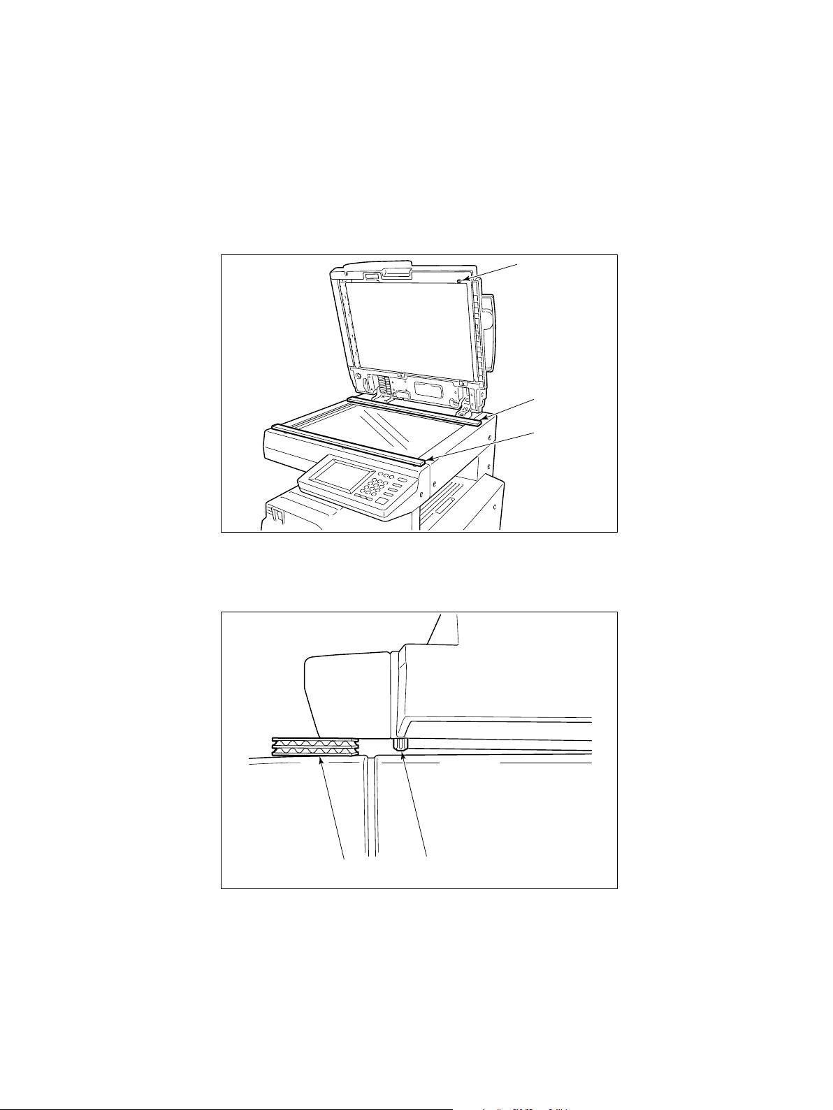
PREPARATION FOR TRANSPORTATION OF COPIER
Before transporting a copier on which mounts the MR-3011/3012, take off the MR3011/3012 or insert a gaggers underneath the MR-3011/3012 as shown in the
following figures.
1. Use pieces of the corrugated board came in the package of MR-3011/3012 or
equivalent as the gaggers. Insert the gaggers as shown in the figure, then close
the MR-3011/3012.
Height positioning
stud
Gagger
Gagger
2. Make sure that the height positioning stud is not in contact with the original
glass.
Gagger
The height positioning stud is not
in contact with the original glass.
Page 5

CONTENTS
1. SPECIFICATION ......................................................................................... 1-1
2. CONFIGURATION....................................................................................... 2-1
3. SECTIONAL VIEW AND DRIVE SYSTEM.................................................. 3-1
3.1 Sectional View ....................................................................................... 3-1
3.2 Drive System ......................................................................................... 3-2
4. SYMBOLS AND LAYOUT OF ELECTRICAL PARTS /
DIAGRAM OF SIGNAL BLOCKS................................................................ 4-1
4.1 Symbols................................................................................................. 4-1
4.2 Layout of Electrical Parts ....................................................................... 4-3
4.3 Diagram of Signal Blocks....................................................................... 4-4
4.4 Description of Interface Signals............................................................. 4-5
5. DESCRIPTION OF OPERATIONS .............................................................. 5-1
5.1 Single Side Feeding .............................................................................. 5-1
5.2 Duplex Feeding...................................................................................... 5-5
5.3 Single Side Feeding (for Mixed Sized Originals).................................... 5-14
6. JAMMING.................................................................................................... 6-1
6.1 Feeding Jam .......................................................................................... 6-1
6.2 Transpor t Jam........................................................................................ 6-1
6.3 Exit Jam................................................................................................. 6-2
6.4 Reversing Jam....................................................................................... 6-2
7. ORIGINAL SIZE DETECTION..................................................................... 7-1
7.1 Method of Original Size Detection (for Standard Sized Originals)..... 7-1
7.2 Relation between Status of Sensor and Original Size
(for Standard Sized Originals) ........................................................... 7-3
7.3 Method of Original Size Detection (for Mixed Sized Original)............ 7-4
7.4 Relation between Status of Sensor and Original Size
(for Mixed Sized Originals) ................................................................ 7-5
8. FLOW CHART ............................................................................................. 8-1
9. TIMING CHART........................................................................................... 9-1
10. DESCRIPTION OF CIRCUITS .................................................................... 10-1
10.1 Input Circuits for Original Length Sensor, Read Sensor
and Reverse Sensor .............................................................................. 10-1
10.2 Irruptive Current Control Circuit............................................................. 10-2
10.3 Drive Circuit for Read Motor .................................................................. 10-3
10.4 Drive Circuit for Reverse Motor.............................................................. 10-4
October 2000 © TOSHIBA TEC MR-3011/3012 CONTENTS
i
Page 6

10.5 Drive Circuit for Feed Motor................................................................... 10-5
10.6 Current Control Circuit for Feed Motor................................................... 10-6
10.7 Drive Circuit for Fan Motor..................................................................... 10-6
10.8 Drive Circuit for Reverse Solenoid......................................................... 10-7
10.9 Reset Circuit .......................................................................................... 10-7
10.10 EEPROM Circuit.................................................................................... 10-8
11. DESCRIPTION OF INPUT/OUTPUT SIGNALS.......................................... 11-1
11.1 REQ Signal, ACK Signal and TxD Signal .............................................. 11-1
11.2 DF-ACK Signal, DF-REQ Signal and RxD Signal.................................. 11-2
11.3 Input Circuits for Sensors ...................................................................... 11-3
12. DISASSEMBLY AND ADJUSTMENT .......................................................... 12-1
12.1 Pickup Roller and Feed Roller ............................................................... 12-1
12.2 Separation Roller................................................................................... 12-2
12.3 Reverse Solenoid .................................................................................. 12-3
12.4 Drive System ......................................................................................... 12-4
12.4.1 Fan motor .......................................................................................... 12-4
12.4.2 Read motor(MR-3011) ...................................................................... 12-5
12.4.3 Read motor(MR-3012) ...................................................................... 12-7
12.4.4 RADF open/close switch ................................................................... 12-8
12.4.5 Feed motor ........................................................................................ 12-9
12.4.6 Reverse motor................................................................................... 12-10
12.4.7 RADF open/close sensor .................................................................. 12-10
12.4.8 PC board ........................................................................................... 12-10
12.4.9 Jam access cover switch ................................................................... 12-10
12.4.10 Feed motor clock sensor .................................................................. 12-11
12.5 Tray sensor ............................................................................................ 12-11
12.6 Empty Sensor, Registration Sensor, Original Width Sensor and
Original Length Sensor.......................................................................... 12-12
12.7 Read Sensor.......................................................................................... 12-13
12.8 Exit Sensor ............................................................................................ 12-13
12.9 Reverse Sensor ..................................................................................... 12-14
12.10 Adjustment of registration...................................................................... 12-15
12.11 Adjustment of original registration for reversing operation..................... 12-16
12.12 Adjustment of reverse solenoid ............................................................. 12-17
12.13 Adjustment of RADF open/close switch................................................. 12-18
12.14 Adjustment of RADF open/close sensor................................................ 12-19
12.15 Adjustment of image skew..................................................................... 12-20
12.16 Adjustment of height (RADF)................................................................. 12-21
12.17 Initialization of EEPROM and Adjustment of Sensors ........................... 12-22
12.18 Attachment of Mylars............................................................................. 12-23
13. SERVICE ..................................................................................................... 13-1
13.1 Troubleshooting for Mechanical Errors .................................................. 13-1
13.2 Troubleshooting for Electrical Errors...................................................... 13-3
October 2000 © TOSHIBA TEC MR-3011/3012 CONTENTS
ii
Page 7

14. ASSEMBLY OF PC BOARD........................................................................ 14-1
15. PERIODIC MAINTENANCE ........................................................................ 15-1
16. CIRCUIT DIAGRAM / HARNESS DIAGRAM .............................................. 16-1
16.1 Circuit Diagram (MR-3011).................................................................... 16-1
16.2 Circuit Diagram (MR-3012).................................................................... 16-2
16.3 Control PC Board Circuit ....................................................................... 16-3
16.4 Harness Diagram (MR-3011)................................................................. 16-4
16.5 Harness Diagram (MR-3012)................................................................. 16-5
October 2000 © TOSHIBA TEC MR-3011/3012 CONTENTS
iii
Page 8

1. SPECIFICATION
Model Name
Capacity of Original Feeding Tray
Feed Speed
Acceptable Original Size
Power Source
Power Consumption
Dimensions
Weight
*Specification and appearance are subject to change without notice due to enhancedment of product quality.
MR-3011/MR-3012
Up to 100 sheets
MR-3011:
Approx.16 sheets/min. (A4 or Letter, feed widthwise) [DP1600]
Approx.20 sheets/min. (A4 or Letter, feed widthwise) [DP2000]
Approx.25 sheets/min. (A4 or Letter, feed widthwise) [DP2500]
MR-3012:
Approx.35 sheets/min. (A4 or Letter, feed widthwise) [DP3500]
Approx.45 sheets/min. (A4 or Letter, feed widthwise) [DP4500]
Smallest...A5-R
Largest...A3
Thickness...50g/m2~127g/m2 (13.3lb~33.8lb)
Power supplied from the copier
48W
W557 × D497.3 × H165 (W22 inches × D19.6 inches × H6.5inches)
Approx.13.6kg or 29.9lb
October 2000 © TOSHIBA TEC MR-3011/3012 SPECIFICATION
1-1
Page 9
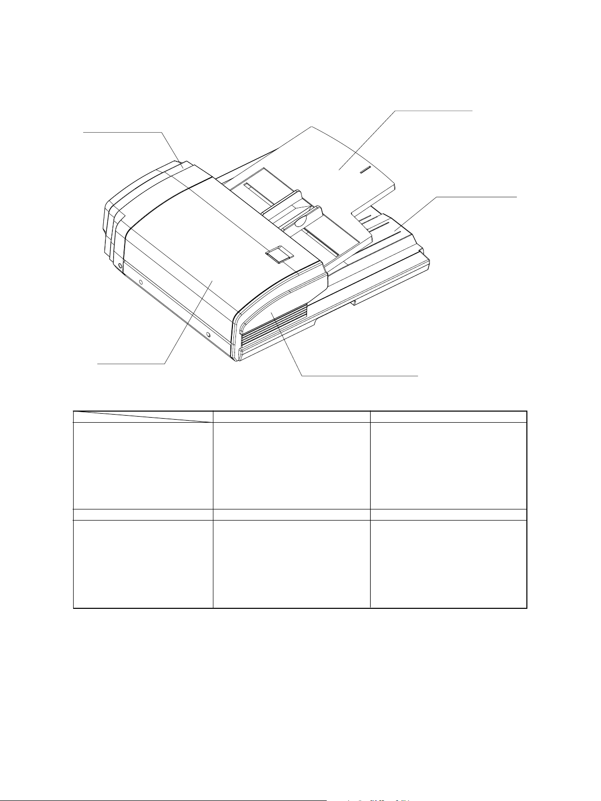
2. CONFIGURATION
Drive/control section
Original feeding tray
Original receiving tray
Jam access cover
Feeding/transportation section
Original feeding tray section
Drive/control section
Mechanical
• Jam access cover
• Pickup roller
• Feed roller
• Separation roller
• Registration roller
• Read roller
• Reverse roller
• Exit roller
• Original feeding tray
Feeding/transportation section
Electrical parts
• Empty sensor
• Original length sensor
• Registration sensor
• Original width sensor
• Read sensor
• Reverse sensor
• Exit sensor
• Tray sensor
• Feed motor
• Read motor
• Reverse motor
• Reverse solenoid
• RADF open/close sensor
• RADF open/close switch
• Jam access cover switch
• PC board
October 2000 © TOSHIBA TEC MR-3011/3012 CONFIGURATION
2-1
Page 10
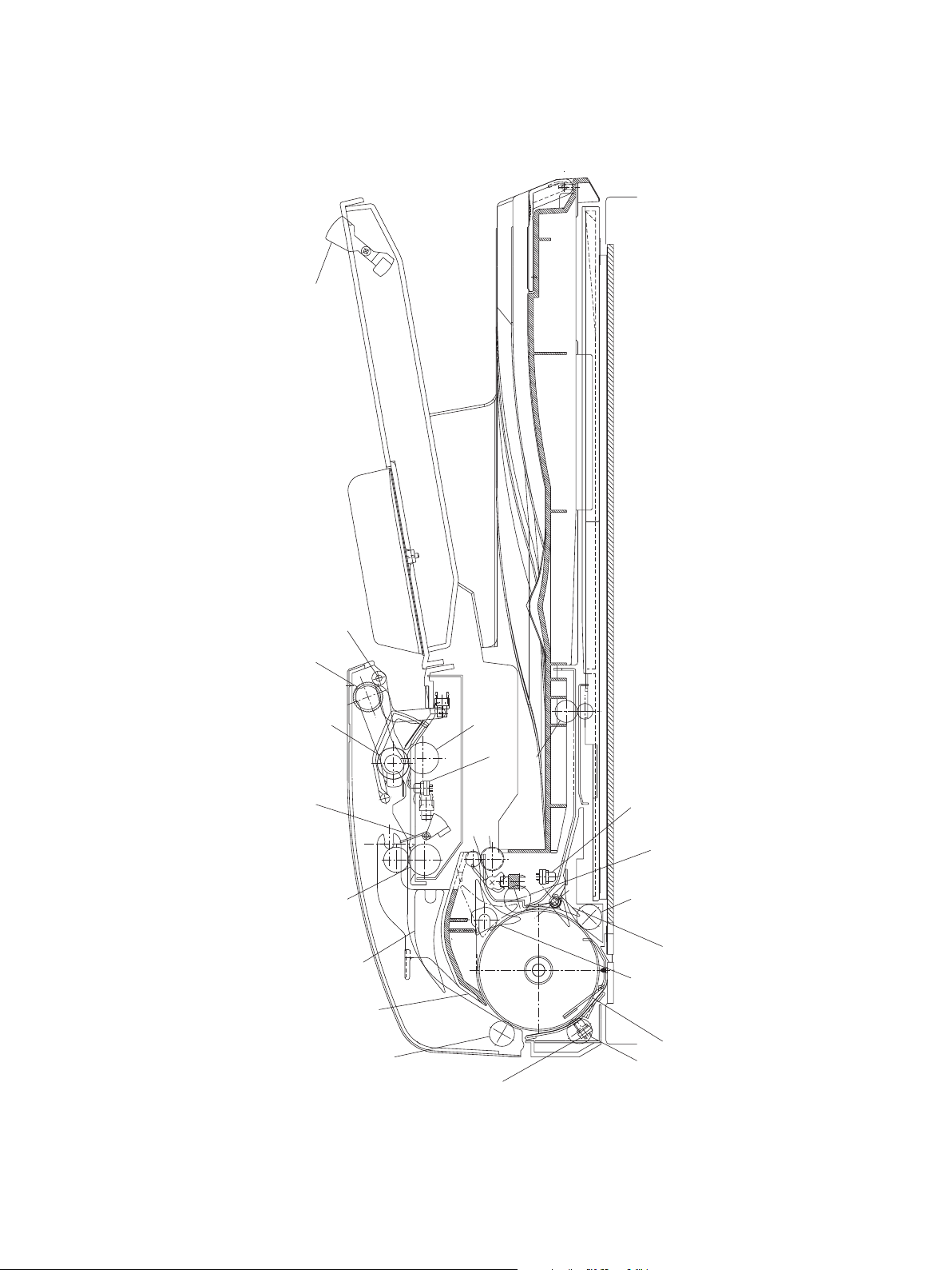
3. SECTIONAL VIEW AND DRIVE SYSTEM
3.1 Sectional View
Tray sensor
Empty lever
Pickup roller
Feed roller
Registration sensor
Original width sensor
Registration roller
Flapper
Reverse guide
Small roller1
Separation roller
Original length
sensor
Exit sensor
Read
Reverse roller
Exit roller
sensor
Reverse sensor
Small roller4
Small roller3
3
Reverse flapper
Exit flapper
Read roller
Small roller2
October 2000 © TOSHIBA TEC MR-3011/3012 SECTIONAL VIEW
3-1
Page 11
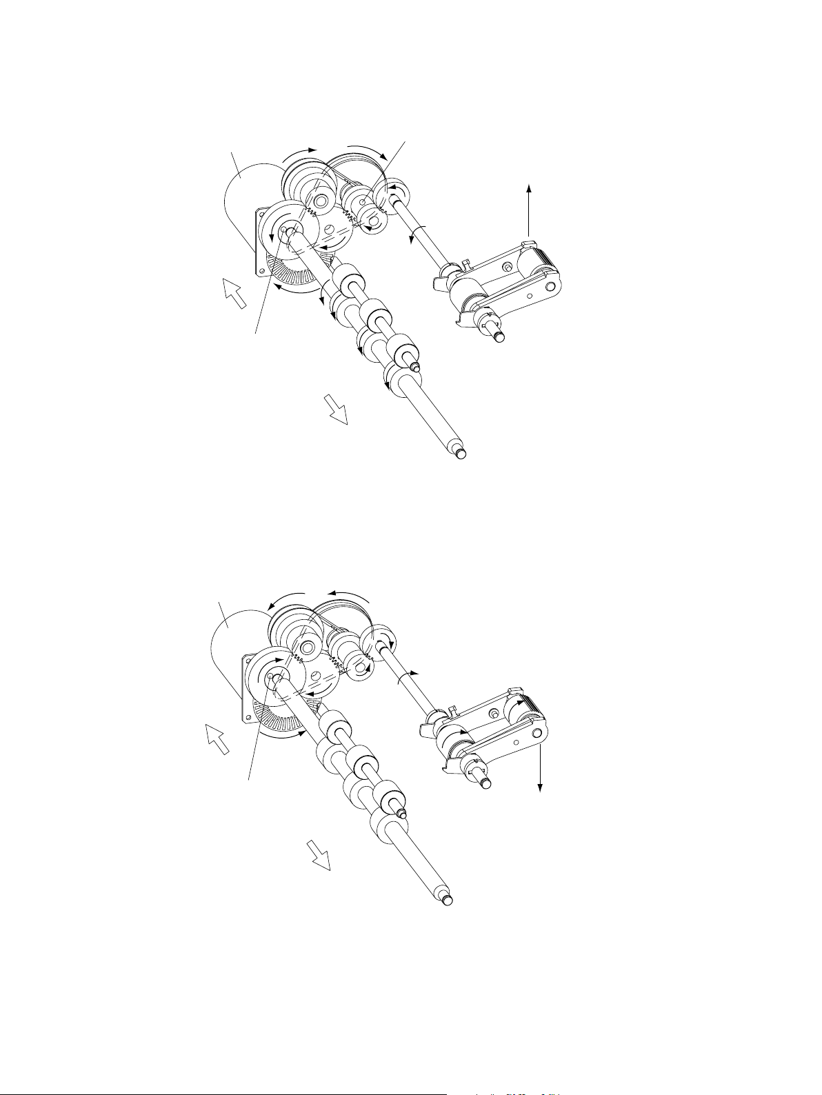
3.2 Drive System
(1) Feed motor rotating clockwise (as seen from the front side)
Feed motor
Rear side
One-way clutch (locked)
Spring clutch
(Stops the drive for the clutch when the
pickup roller reaches its upper limit position)
Pickup roller (lifted up)
Front side
Motor rotating clockwise to transport original
(2) Feed motor rotating counterclockwise (as seen from the front side)
Feed motor
Rear side
One-way clutch (slipped)
Front side
Motor rotating counterclockwise to transport original
Pickup roller (Down)
October 2000 © TOSHIBA TEC MR-3011/3012 SECTIONAL VIEW
3-2
Page 12

(3) Read motor rotating clockwise (as seen from the front side)
Reverse motor
Read motor
Rear side
Reverse motor rotating clockwise
to carry original to the reverse path.
Reverse roller
Exit roller
Front side
Transportation, scanning and original exit
(read motor rotating clockwise)
Read roller
(4) Read motor rotating counterclockwise (as seen from the front side)
Reverse motor
Read motor
Rear side
Reverse motor rotating counterclockwise
for back side registration and original discharge.
One-way gear
Reverse roller
Exit roller
Front side
Read motor rotating counterclockwise
to transport mixed sized originals.
Read roller
October 2000 © TOSHIBA TEC MR-3011/3012 SECTIONAL VIEW
3-3
One-way gear
Page 13

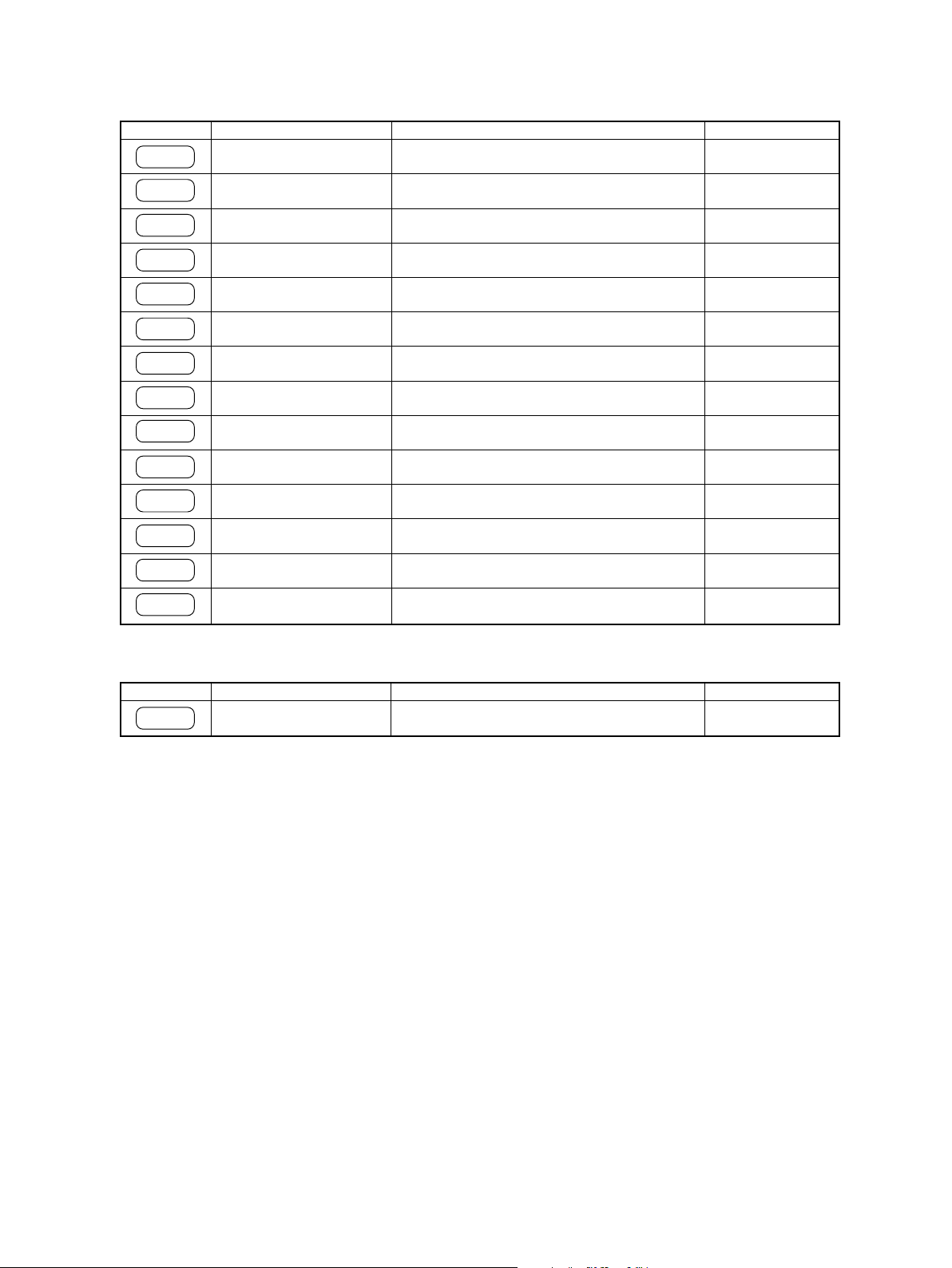
4. SYMBOLS AND LAYOUT OF ELECTRICAL PARTS / DIAGRAM OF SIGNAL BLOCKS
4.1 Symbols
(1) Motors
Symbol
RDMOT
RVMOT
FMOT
FAN
(2) Solenoid
Symbol
RSOL
Name
RDMOT
(Read motor)
RVMOT
(Reverse motor)
FMOT
(Feed motor)
FAN
(Fan motor)
Name
RSOL
(Reverse solenoid)
Function
Drives transportation roller and exit roller
Drives reverse roller
Drives pickup roller, feed roller and registration
roller
Cools down read motor
Function
Switches flapper
Remarks
Pulse motor
Pulse motor
DC motor
Fan motor
Remarks
DC solenoid
October 2000 © TOSHIBA TEC MR-3011/3012 SYMBOLS
4-1
Page 14
(3) Switches and Sensors
Symbol
JAMSW
OPNSW
EMPS
REGS
EXITS
SIZES1
SIZES2
SIZES3
TRYS
OPNSN
MCLK
LENGS
READS
RVRS
Name
JAM-SW
(Jam access cover switch)
RADF-OPN-SW
(RADF open/close switch)
EMP-SNS
(Empty sensor)
REG-SNS
(Registration sensor)
EXIT-SNS
(Exit sensor)
SIZE-SNS 1
(Original width sensor 1)
SIZE-SNS 2
(Original width sensor 2)
SIZE-SNS 3
(Original width sensor 3)
TRY-SNS
(Tray sensor)
RADF-OPN-SNS
(RADF open/close sensor)
MCLK-SNS
(Feed motor clock sensor)
LENG-SNS
(Original length sensor)
Read-SNS
(Read sensor)
RVR-SNS
(Reverse sensor)
Function
Switch to detect if jam access cover for feeding
unit is opened/closed
Switch to detect if RADF unit is opened/closed
Sensor to detect original on original tray
Sensor to detect original at registration position
Sensor to deteat original at exit area
Original width detection sensor 1
Original width detection sensor 2
Original width detection sensor 3
Sensor to detect length of original on original
tray
Sensor to detect if RADF unit is opened/closed
Detection sensor for feed motor clock
Sensor to detect length of original
Sensor to detect leading edge of original at
scanning position
Sensor to detect original at reverse position
Remarks
Microswitch
Microswitch
Semiconductive
optical sensor
Semiconductive
optical sensor
Semiconductive
optical sensor
Semiconductive
optical sensor
Semiconductive
optical sensor
Semiconductive
optical sensor
Semiconductive
optical sensor
Semiconductive
optical sensor
Semiconductive
optical sensor
Semiconductive
optical sensor
Semiconductive
optical sensor
Semiconductive
optical sensor
(4) PC board
Symbol
PWA-DF
PWA-LGC-RADF
(PC board)
Function
Drives feeding and transportation
RemarksName
October 2000 © TOSHIBA TEC MR-3011/3012 SYMBOLS
4-2
Page 15

4.2 Layout of Electrical Parts
JAMSW
TRYS
FMOT
RDMOT
FAN
OPNSW
MCLK
RVRS
READS
RVMOT
EMPS
OPNS
SIZES1
SIZES3
REGS
EXITS
LENGS
SIZES2
RSOL
RDMOT Read motor
RVMOT Reverse motor
FMOT Feed motor
FAN Fan motor
RSOL Reverse solenoid
JAMSW Jam access cover switch
OPNSW RADF open/close switch
EMPS Empty sensor
REGS Registration sensor
EXITS Exit sensor
SIZE 1 Original width sensor 1
SIZE 2 Original width sensor 2
SIZE 3 Original width sensor 3
TRYS Tray sensor
OPNS RADF open/close sensor
MCLK Feed motor clock sensor
LENGS Orignal length sensor
READS Read sensor
RVRS Reverse sensor
October 2000 © TOSHIBA TEC MR-3011/3012 SYMBOLS
4-3
Page 16
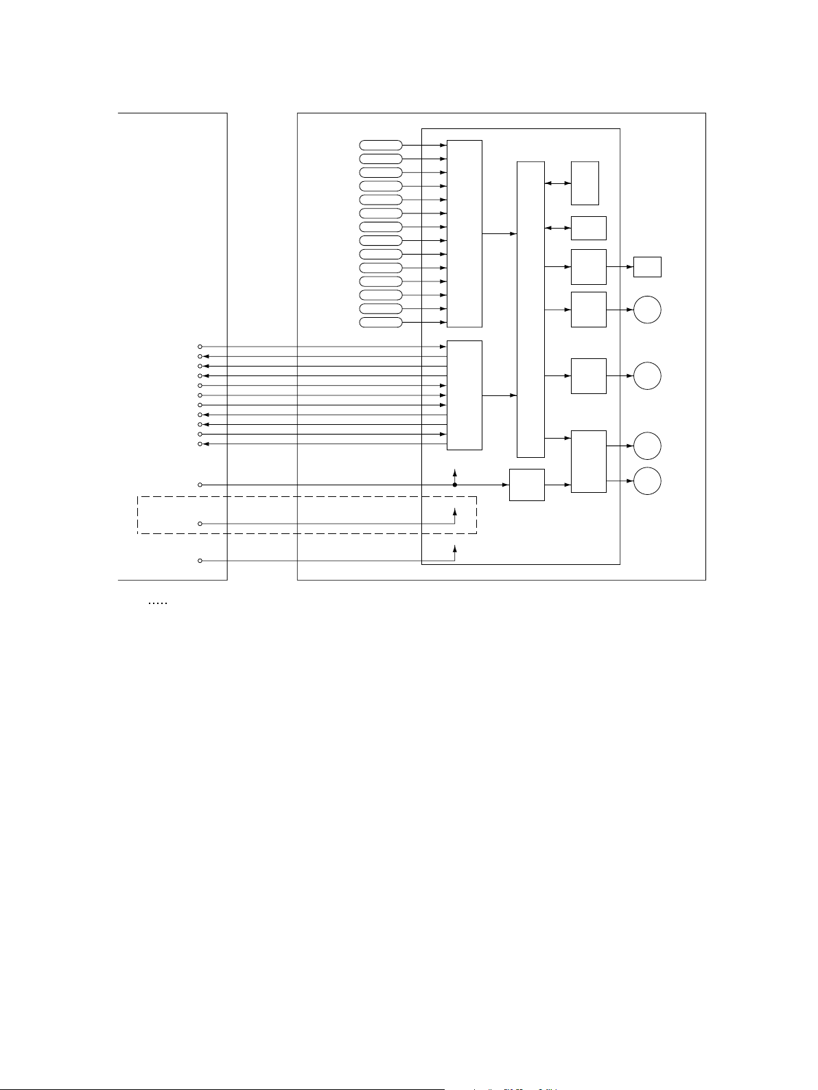
4.3 Diagram of Signal Blocks
PPC (copier)
ACK
VARID
EMPTY
RxD
SGND
TxD
SGND
DF-ACK
DF-REQ
REQ
RADFCNT
DC+24V
(Supplied from copier)
*1
P+5V
(
Supplied from copier
DC+5V
Supplied from copier
(
RADF (Reversing Automatic Document Feeder)
JAMSWJAM-SW
OPNSWRADF-OPN-SW
EMPSEMP-SNS
REGSREG-SNS
EXITSEXIT-SNS
SIZES1SIZE-SNS1
SIZES2SIZE-SNS2
SIZES3SIZE-SNS3
TRYSTRY-SNS
OPNSRADF-OPN-SNS
MCLKMCLK-SNS
LENGSLENG-SNS
READSREAD-SNS
RVRSRVR-SNS
PWA-LGC-F513
Sensor
input
circuit
Communication
circuit
DC+24V
P+5V
CPU
Irruptive
current
control
circuit
ROM
EEPROM
Driver
Driver
Driver
Driver
RSOL
RSOL
FAN
FAN
FMOT FMOT
RDMOT
RDMOT
RVMOT
RVMOT
)
DC+5V
)
*1 Available only for MR-3011
October 2000 © TOSHIBA TEC MR-3011/3012 SYMBOLS
4-4
Page 17
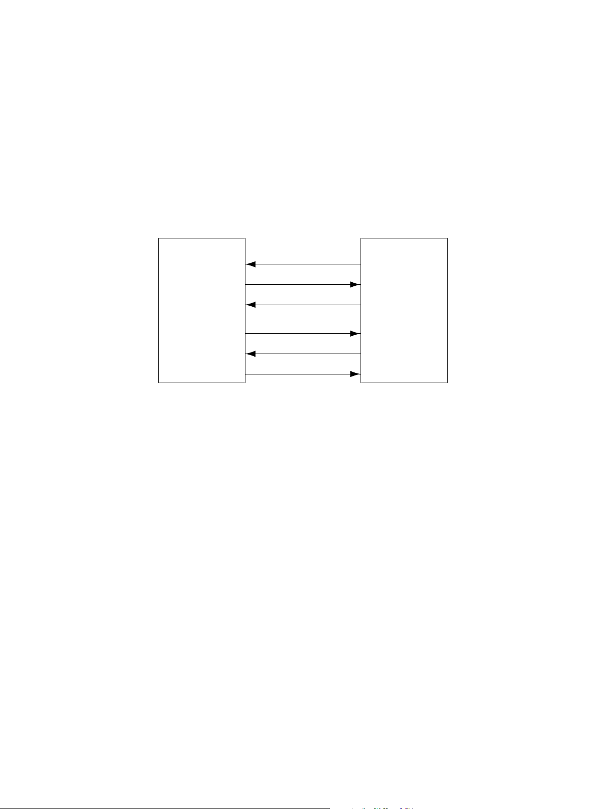
4.4 Description of Interface Signals
The following 6 lines are used to send/receive signals between the copier and the RADF.
REQ ............. Communication request signal (from copier to RADF)
DF-REQ ....... Communication request signal (from RADF to copier)
DF-ACK........Response signal for communication request signal (from RADF to copier)
ACK..............Response signal for communication request signal (from copier to RADF)
TxD ..............Data sent from copier to RADF
RxD ..............Data sent from RADF to copier
Data communication (RxD and TxD) between the scanner and RADF has adopted the serial communication
system which does not allow checking using testing devices to see whether the signals are sent/received
properly in the field.
RADF Copier
REQ
DF-ACK
TxD
DF-REQ
ACK
RxD
October 2000 © TOSHIBA TEC MR-3011/3012 SYMBOLS
4-5
Page 18
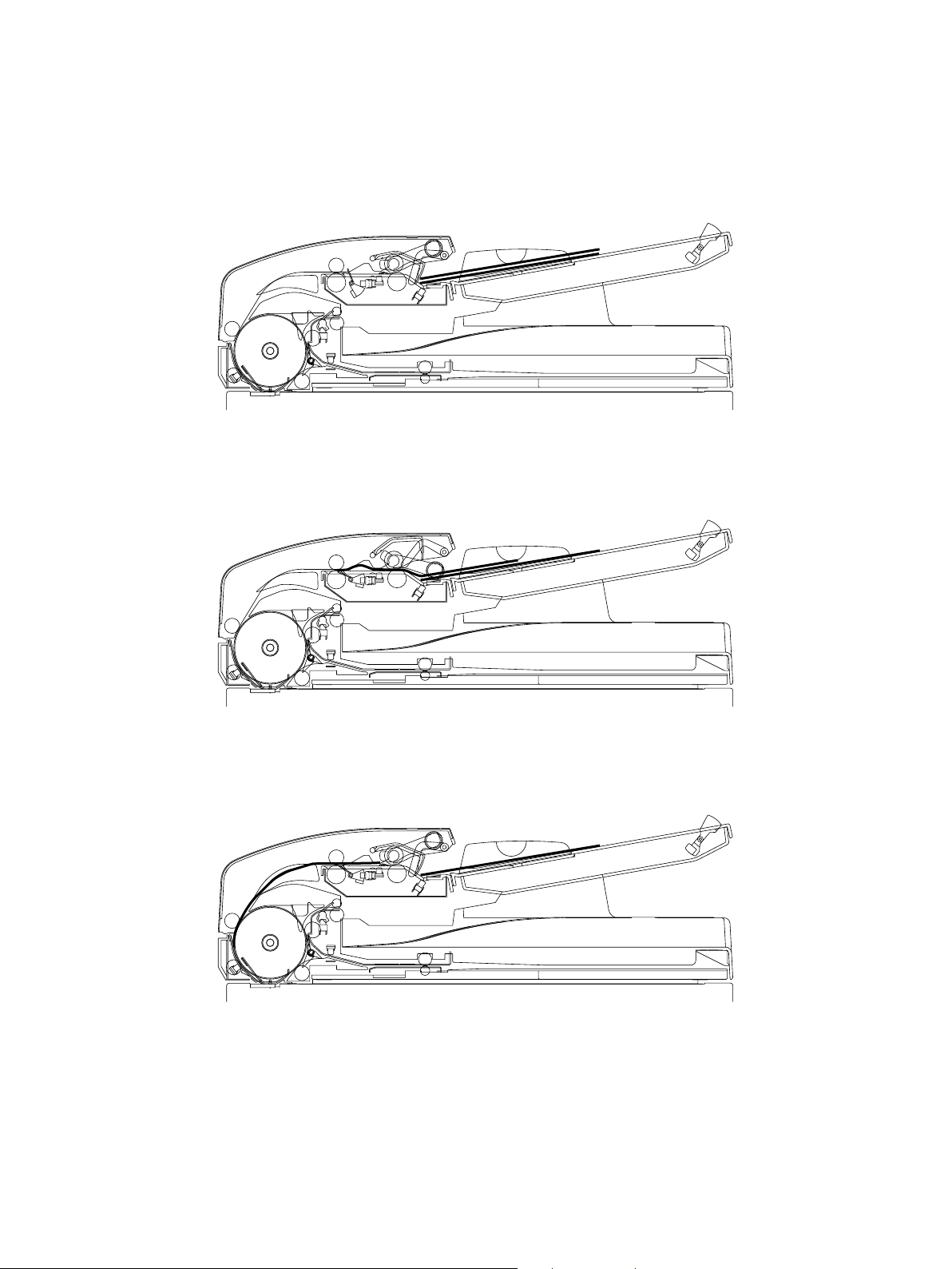
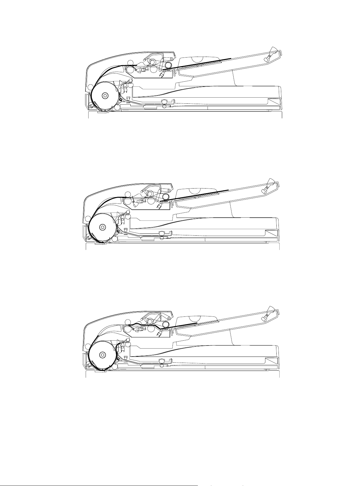
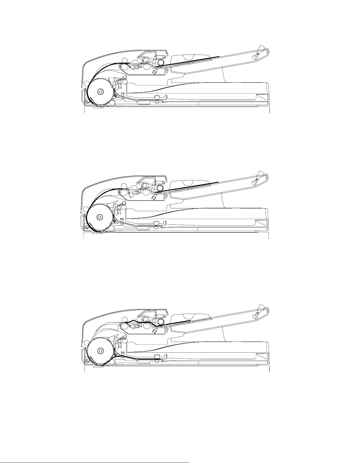
5. DESCRIPTION OF OPERATIONS
5.1 Single Side Feeding
(A4, registration ratio 100%)
(1) Setting original
The original is set on the tray and the empty sensor is turned ON.
The original set signal becomes ON.
(2) Start of pre-feeding operation n Completion of pre-feeding operation
A feed signal is sent from the main unit, and the feed motor rotates the pickup roller and feed motor to start
feeding the original (pre-feeding operation).
(3) Start of feeding operation n Original length sensor OFF
The feed motor starts to rotate in reverse and the read motor rotates forward to rotate the registration roller and
the read roller while the original is waiting in front of the registration roller and read roller starts to be transported.
The feed motor is stopped after the original length sensor is turned OFF.
October 2000 © TOSHIBA TEC MR-3011/3012 DESCRIPTION OF OPERATION
5-1
Page 19
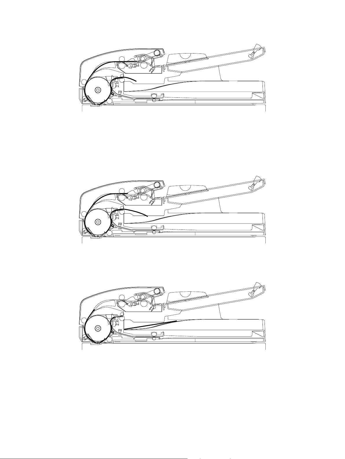
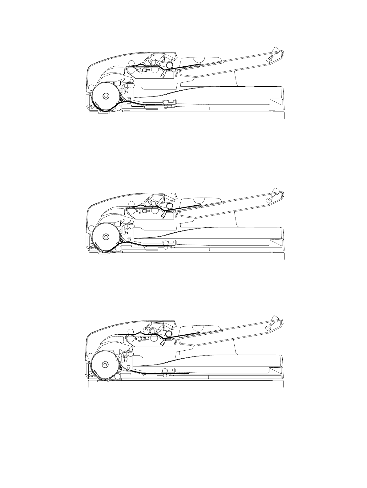
(4) Original length sensor OFF n Completion of sending operation
If the next original is waiting in the tray, the pickup roller is lowered after the feed motor which has started to
rotate forward rotates for a cer tain number of pulses. (The pickup roller waits for the next pre-feeding operation in
that lowered position.)
The read motor rotates for a certain number of pulses and stops after the read sensor is turned ON. (The leading
edge of the original reaches the pre-scanning position.)
(5) Start of scanning operation n Star t of pre-feeding operation for next original
The original transport signal is sent from the main unit, and the read motor starts to rotate forward. The read
roller and exit roller are rotated to start scanning the original. The feed motor rotates the pickup roller and feed
roller after the trailing edge of the original has passed the registration roller to start the pre-feeding operation for
the next original.
(6) Start of pre-feeding operation for next original n Completion of pre-feeding operation
After the registration sensor has detected the leading edge of the original. The feed motor transports the original
for a certain number of pulses, performs registration and stops.
October 2000 © TOSHIBA TEC MR-3011/3012 DESCRIPTION OF OPERATION
5-2
Page 20
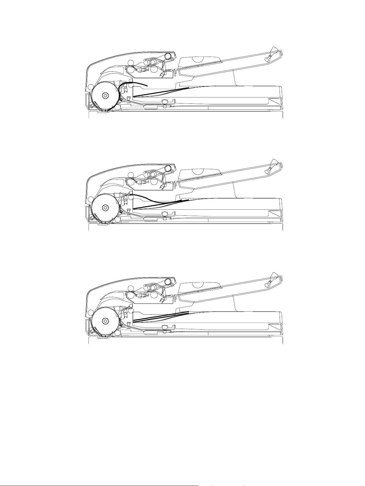
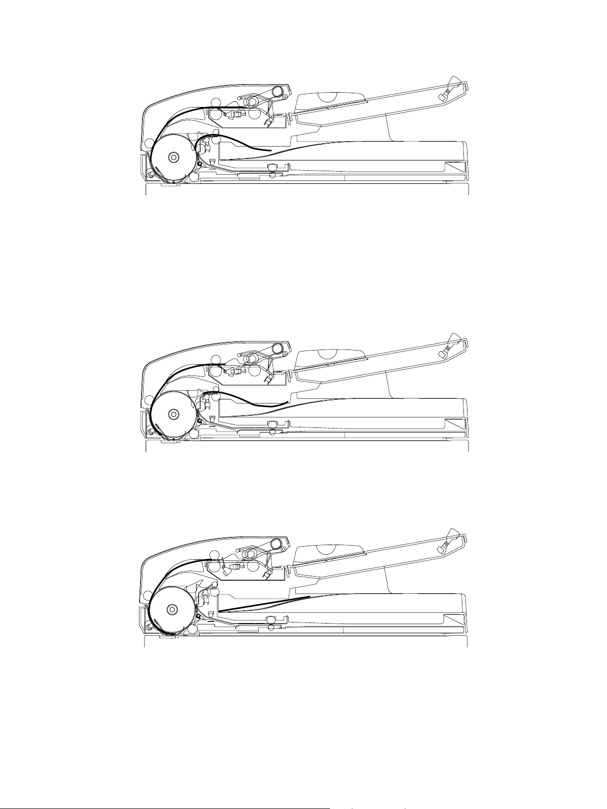
(7) Start of feeding operation for next original n Completion of scanning operation
The feed motor starts to rotate in reverse, it rotates the registration roller to feed the next original waiting in front
of the registration roller and read roller.
The original set signal is reset when the empty sensor is turned OFF. The feed motor is stopped after the original
length sensor is turned OFF.
The scanning operation is completed when the trailing edge of the original being scanned has passed the
scanning position.
(8) Completion of scanning operation n Completion of feeding operation for next original
The read motor rotates for a certain number of pulses and stops after the read sensor is turned ON.
(The leading edge of the next original reaches the pre-scanning position.)
(9) Start of scanning operation for next original n Completion of original discharge
The read motor starts to rotate forward, it rotates the read roller and exit roller to start scanning the next original.
Original discharge is completed when the trailing edge of the original has passed the exit roller.
October 2000 © TOSHIBA TEC MR-3011/3012 DESCRIPTION OF OPERATION
5-3
Page 21
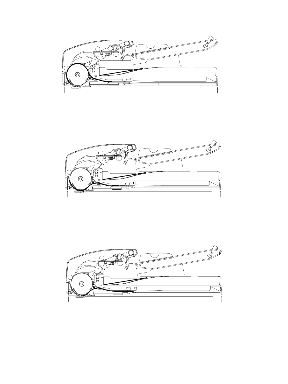
(10)Completion of scanning operation for next original
Scanning is completed when the trailing edge of the next original has passed the scanning position and the
original is carried toward the receiving tray.
(11)Exit sensor OFF (next original)
After the exit sensor is turned OFF, the feed motor rotates for a certain number of pulses till the original is
completely discharged.
(12) Completion of or iginal discharge (next original)
The read motor is stopped when the next original is completely discharged into the receiving tray.
October 2000 © TOSHIBA TEC MR-3011/3012 DESCRIPTION OF OPERATION
5-4
Page 22
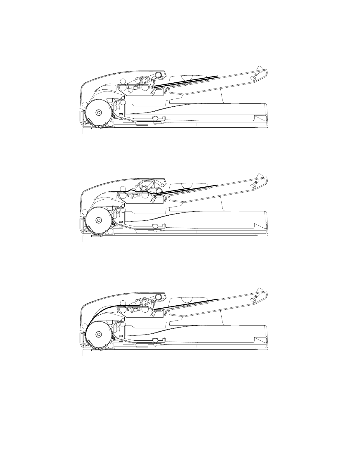
5.2 Duplex Feeding
(A4, reproduction ratio 100%)
(1) Setting original
The original is set on the tray and the empty sensor is turned ON.
The original set signal becomes ON.
(2) Start of pre-feeding operation n Completion of pre-feeding operation
A feed signal is sent from the main unit, and the feed motor starts to rotate forward and rotates the pickup roller
and feed roller to start the pre-feeding operation. After the registration sensor detected the leading edge of the
original, the feed motor transports the original for a certain number of pulses, performs registration and stops.
(3) Start of feeding operation n Original length sensor OFF
The feed motor starts to rotate in reverse and the read motor starts to rotate forward to start feeding the original
waiting in front of the registration roller and the read roller. The feed motor is stopped after the original length
sensor is turned OFF.
October 2000 © TOSHIBA TEC MR-3011/3012 DESCRIPTION OF OPERATION
5-5
Page 23
(4) Original length sensor OFF n Completion of feeding operation
If the next original is waiting on the tray, the pickup roller is lowered after the feed motor started to rotate forward
rotates for a certain number of pulse. (The pickup roller waits for next pre-feeding operation in that lowered
position.)
The read motor rotates for a certain number of pulses and stops after the read sensor is turned ON. (The leading
edge of the original reaches the pre-front side scanning position.)
(5) Start of front side scanning operation n Star t of pre-feeding operation for next original
An original transport signal is sent from the main unit, and the read motor and reverse motor start to rotate
forward. The read roller, exit roller and reverse roller are then rotated. The reverse flapper is switched toward the
reverse position by turning ON the reverse solenoid and the front side of the original, star ts to be scanned.
The feed motor rotates the pickup roller and feed roller after the trailing edge of the original has passed the
registration roller, to start the pre-feeding operation for the next original.
(6) Start of pre-feeding operation for next original n Completion of pre-feeding operation n Completion of front-
side scanning operation
After the registration sensor has detected the leading edge of the next original, the feed motor transports the
original for a certain number of pulses, performs registration and stops. Scanning of the front side of original is
completed when the trailing edge of the original being scanned has passed the scanning position.
October 2000 © TOSHIBA TEC MR-3011/3012 DESCRIPTION OF OPERATION
5-6
Page 24

(7) Completion of transport operation for front side of original (original paused at reverse position)
The read motor and reverse motor are stopped after the reverse sensor is turned OFF to complete transpor tation of the front side of the original.
(8) Start of back side registration operation n Completion of registration
The reverse motor starts to rotate in reverse and rotates the reverse roller in reverse to start the registration
operation for the back side of the original pausing at the reverse position.
After the reverse sensor has detected the trailing edge of the original, the feed motor transpor ts the or iginal for a
certain number of pulses, performs registration and stops.
(9) Start of reverse feeding operation n Completion of reverse feeding operation
The read motor starts to rotate forward and the reverse motor starts to rotate in reverse. The read roller, exit
roller and reverse roller are rotated to start the reverse feeding operation for the original waiting at the back side
registration position. The read motor and reverse motor rotate for a cer tain number of pulses and stop after the
read sensor is turned ON. (The leading edge of the original reaches the pre-back side scanning position.)
October 2000 © TOSHIBA TEC MR-3011/3012 DESCRIPTION OF OPERATION
5-7
Page 25
(10)Start of back side scanning operation n Or iginal passing reverse position
An original transport signal is sent from the main unit, and the read motor starts to rotate forward and reverse
motor starts its reverse rotation activated by read rotate in reverse to rotate the read roller, exit roller and reverse
roller. The reverse flapper is switched toward the reverse position by turning ON the reverse solenoid to start
scanning the back side of the original.
The reversal motor rotates for a cer tain number of pulses and stops after the trailing edge of the original has
passed the reverse roller.
(11)Original passing reverse position n Completion of back side scanning operation
The reversal motor starts to rotate forward and rotates the reverse roller to be ready for the leading edge of the
original to come into the reverse position.
The scanning operation for the back side of the original is completed when the trailing edge of the original has
passed the scanning position.
(12)Completion of transport operation for back side of original (original paused at reverse position)
The read motor and reverse motor are stopped after the reverse sensor is turned OFF to complete transpor tation of the back side of the original.
The reverse flapper is switched to the exit side by turning OFF the reverse solenoid.
October 2000 © TOSHIBA TEC MR-3011/3012 DESCRIPTION OF OPERATION
5-8
Page 26
(13)Start of reverse discharge n Start of feeding operation for next original n Original length sensor OFF
The read motor starts to rotate forward and the reverse motor starts to rotate in reverse. The read roller, exit
roller and reverse roller are rotated to start reverse discharge of the original paused at the reverse position. The
feed motor rotates for a certain number of pulses after the reverse sensor is turned ON. It then starts to rotate in
reverse to rotate the registration roller, and starts the feeding operation for the next original waiting in front of the
read roller and registration roller.
The original set signal is reset when the empty sensor is turned OFF.
The reverse motor is stopped after the reverse sensor is turned OFF.
The feed motor is stopped after the original length sensor is turned OFF.
(14)Original length sensor OFF n Completion of feeding operation for next original
The read motor rotates for a certain number of pulses and stops after the read sensor is turned ON. (The leading
edge of the next original reaches the pre-scanning position for front side of original.)
(15)Start of front side scanning operation pre-scanning position for front side of original n Completion of
reverse discharge operation
The read motor and reverse motor start to rotate forward to rotate the read roller, exit roller and reverse roller.
The reverse flapper is switched toward the reverse position by turning ON the reverse solenoid to star t the
scanning of the front side of next original.
The reverse discharge operation is completed when the trailing edge of the original has passed the exit roller.
October 2000 © TOSHIBA TEC MR-3011/3012 DESCRIPTION OF OPERATION
5-9
Page 27

(16)Completion of front side scanning operation
The scanning operation for the front side of the original is completed when the trailing edge of next original has
passed the scanning position.
(17)Completion of transport operation for the front side of next original (original paused at reverse position)
The read motor and reverse motor are stopped when the reverse sensor is turned OFF to complete the transpor t
operation for the front side of the original.
(18)Start of back side registration n Completion of back side registration
The reverse motor starts to rotate in reverse and the reverse roller rotates in reverse to start the registration of
the next original paused at the reverse position.
After the reverse sensor has detected the leading edge of the original, the reverse motor transpor ts the original
for a certain number of pulses, performs registration and stops.
October 2000 © TOSHIBA TEC MR-3011/3012 DESCRIPTION OF OPERATION
5-10
Page 28
(19)Start of reverse feeding operation for next original n Completion of reverse feeding operation
The read motor starts to rotate forward and the revese motor starts to rotate in reverse. The read roller, exit roller
and reverse roller are rotated to start the reverse feeding operation for the next original waiting at the back side
registration position. The read motor and reverse motor rotate for a cer tain number of pulses and stop after the
read sensor has been turned ON.
(The leading edge of next original reaches the pre-scanning position for the back side of the original.)
(20)Start of back side scanning operation n Or iginal passing reverse position
The read motor starts to rotate forward and the reverse motor starts to rotate in reverse to rotate the read roller,
exit roller and reverse roller. The reverse flapper is switched toward the reverse position by tur ning ON the
reverse solenoid to start scanning the back side of the next original.
The reverse motor rotates for a cer tain number of pulses and stops after the trailing edge of the next original has
passed the reverse roller.
(21)Next original passing reverse position n Completion of back side scanning
The reverse motor starts to rotate forward and the reverse roller is rotated to be ready for the leading edge of the
next original to come into the reverse position.
The scanning of the back side of the original is completed when the trailing edge of the next original has passed
the scanning position.
October 2000 © TOSHIBA TEC MR-3011/3012 DESCRIPTION OF OPERATION
5-11
Page 29
(22)Completion of transport operation for back side of next original (original paused at reverse position)
The read motor and reverse motor stop after the reverse sensor is turned OFF to complete transpor tation of the
back side of the original. The reverse flapper is switched to the exit side by turning OFF the reverse solenoid.
(23)Start of reverse discharge operation of next original n Start of feeding operation for next original n Or iginal
length sensor OFF
The read motor starts to rotate forward and the reverse motor starts to rotate in reverse. The read roller, exit
roller and reverse roller are rotated to start the reverse discharge of the next original paused at the reverse
position. The reverse motor stops after the reverse sensor has been turned OFF.
(24)Exit sensor OFF
After the exit sensor has been turned OFF, read motor rotates for a certain number of pulses till the next original
has completely discharge.
October 2000 © TOSHIBA TEC MR-3011/3012 DESCRIPTION OF OPERATION
5-12
Page 30

(25)Completion of reverse discharge operation for next original
The read motor is stopped when the next original is completely discharged into the original receiving tray to
terminate the reverse discharge operation.
October 2000 © TOSHIBA TEC MR-3011/3012 DESCRIPTION OF OPERATION
5-13
Page 31

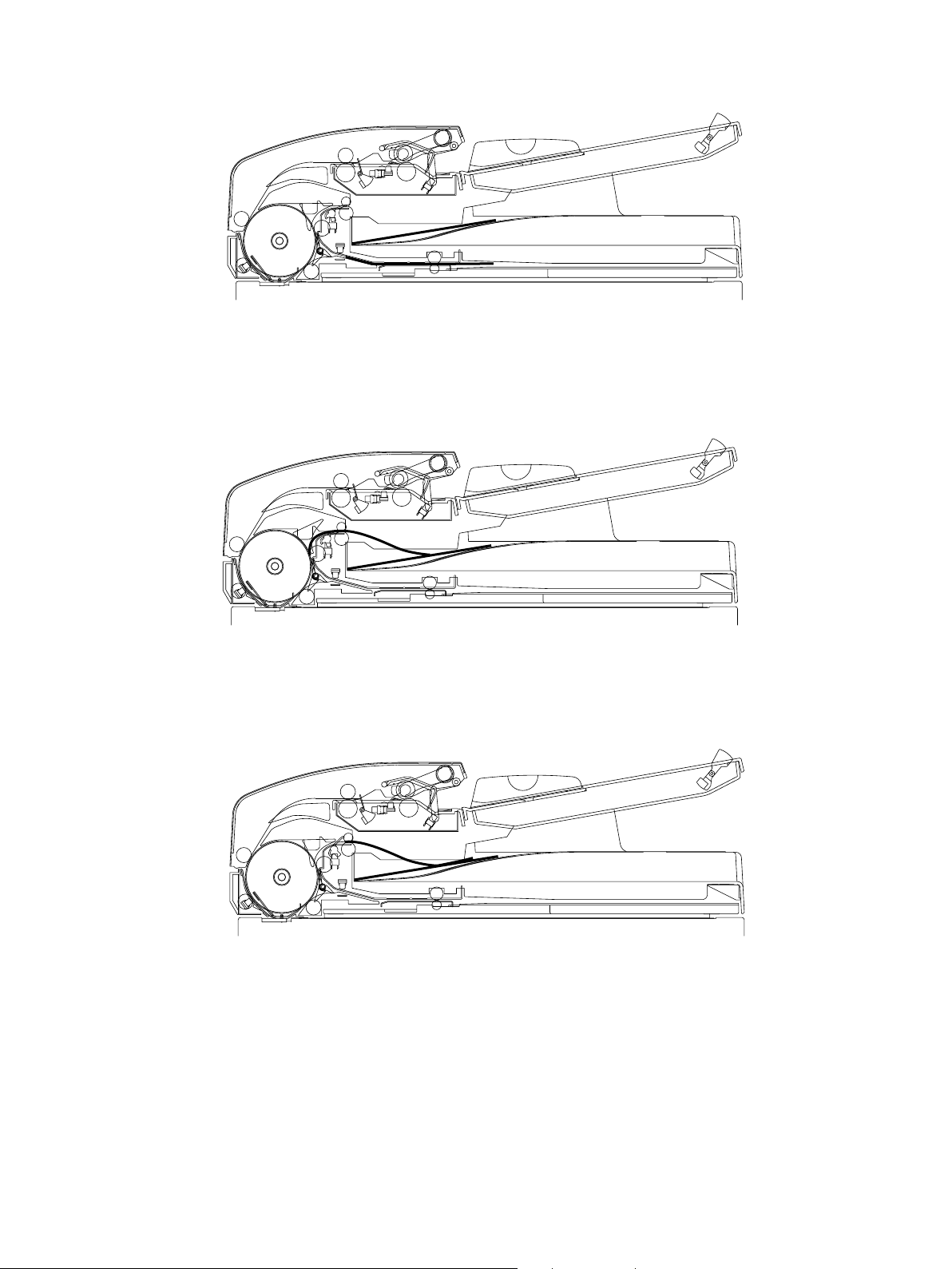
5.3 Single Side Feeding (for Mixed Sized Originals)
(Mixture of A4-R and FOLIO (LTR/LG), reproduction ratio 100%)
(1) Setting original
An original is set on the tray and the empty sensor is turned ON.
The original set signal becomes ON.
(2) Start of pre-feeding operation n Completion of pre-feeding operation
The feed signal is sent from the main unit, and the feed motor starts to rotate forward. The pickup roller and feed
roller are rotated to start the pre-feeding operation. After the registration sensor has detected the leading edge of
the original, the feed motor transports the original for a cer tain number of pulses, performs registration and
stops.
(3) Start of feeding operation n Completion of feeding operation
The feed motor starts to rotate in reverse and the read motor starts to rotate forward. The registration roller and
read roller, exit roller are rotated to star t feeding the original waiting in front of the registration roller and read
roller.
The feed motor stops and the read motor rotates for a certain number of pulses and stops when the read sensor
is turned ON. (The leading edge of the original reaches the pre-scanning position)
October 2000 © TOSHIBA TEC MR-3011/3012 DESCRIPTION OF OPERATION
5-14
Page 32

(4) Start of transpor t operation n Original length sensor OFF
The read motor starts to rotate forward and rotates the read roller and exit roller to start transportation of the
original paused at the scanning position. (The original is transported to determine its lengthwise size along the
feeding direction.)
(5) Original length sensor OFF n Completion of downswing operation of pickup roller
The pickup roller is lowered after the feed motor has started to rotate forward and has rotated for a certain
number of pulses. (The pickup roller waits for the next pre-feeding operation in the lowered position.)
(6) Completion of downswing operation of pickup roller n Pre-reverse position for mixed sized original
The read motor rotates for a certain number of pulse and stops after the original length sensor has been turned
OFF. (The trailing edge of the original reaches the pre-reverse position.)
October 2000 © TOSHIBA TEC MR-3011/3012 DESCRIPTION OF OPERATION
5-15
Page 33

(7) Start of reverse operation for mixed sized originals n Completion of reverse operation
The gate for the reverse path is switched after a certain period of time. The read motor starts to rotate in reverse
and rotates the read roller and exit roller in reverse to star t the reverse operation.
The read motor rotates for a certain number of pulses and stops after the read sensor has been turned OFF.
(8) Start of transpor tation n Completion of transpor tation
The read motor starts to rotate forward and rotates the read roller and exit roller to start the transportation of the
original to the pre-scanning position.
The read motor rotates for a certain number of pulses and stops after the read sensor has been turned ON. (The
leading edge of the original reaches the pre-scanning position.)
(9) Start of scanning operation n Star t of pre-feeding operation for next original n Completion of pre-feeding
operation
A transport signal is sent from the main unit, and the read motor star ts to rotate forward. The read roller and exit
roller is rotated to start scanning the or iginal. The feed motor rotates pickup roller and feed roller to start the prefeeding operation for the next original.
After the registration sensor has detected the leading edge of the original, the feed motor transports the original
for a certain number of pulses, performs registration and stops.
October 2000 © TOSHIBA TEC MR-3011/3012 DESCRIPTION OF OPERATION
5-16
Page 34

(10) Completion of scanning operation
Scanning is completed when the trailing edge of the original has passed the scanning position.
(11)Exit sensor OFF n Start of feeding operation for next original
The feed motor starts to rotate in reverse after the exit sensor has been turned OFF and rotates the registration
roller to start feeding the next original waiting in front of the registration roller and read roller.
The original discharge operation is completed when the trailing edge of the original has passed the exit roller.
(12)Completion of feeding operation for next original
The feed motor stops and the read motor rotates for a certain number of pulses and stops when the read sensor
has been turned ON. (The leading edge of the next original reaches the pre-scanning position.)
October 2000 © TOSHIBA TEC MR-3011/3012 DESCRIPTION OF OPERATION
5-17
Page 35

(13)Start of transportation of next original n Original length sensor OFF
The read motor starts to rotate forward and rotates the read roller and exit roller to transport the next original
paused at the scanning position.
(The original is transported to deter mine its lengthwise size along the feeding direction.)
The original set signal is reset when the empty sensor is turned OFF.
(14)Original length sensor OFF (for next original) n Pre-reverse position for mixed sized originals
The read motor rotates for a certain number of pulses and stops after the original length sensor has been turned
OFF. (The trailing edge of the next original reaches the pre-reverse position.)
(15)Start of reverse operation for the next mixed sized original n Completion of reverse operation
The gate for the reverse path is switched after a certain period of time. The read motor starts to rotate in reverse
and rotates the read roller and exit roller in reverse to star t the reverse operation.
The read motor rotates for a certain number of pulses and stops after the read sensor has been turned OFF.
October 2000 © TOSHIBA TEC MR-3011/3012 DESCRIPTION OF OPERATION
5-18
Page 36

(16)Start of transportation of next original n Completion of transportation
The read motor starts to rotate forward and rotates the read roller and exit roller to start the transportation of the
next original to the pre-scanning position.
The read motor rotates for a certain number of pulses and stops after the read sensor has been turned ON. (The
leading edge of the next original reaches the pre-scanning position.)
(17)Start of scanning operation for next original
A transport signal is sent from the main unit and the read motor star ts to rotate forward. The read roller and exit
roller is rotated to start scanning the next original.
(18)Completion of scanning operation for next original
Scanning is completed when the trailing edge of the next original has passed the scanning position.
October 2000 © TOSHIBA TEC MR-3011/3012 DESCRIPTION OF OPERATION
5-19
Page 37

(19)Exit sensor OFF n Completion of discharge operation for next or iginal
After the exit sensor has been turned OFF, the read motor rotates for a certain number of pulses till the next
original is completely discharge into the tray. The read motor is stopped when the next original is completely
discharge into the receiving tray to complete the original discharge operation.
None: (Duplex feeding of mixed-sized originals)
The reverse mechanism detects the size of the mixed-sized originals consisting of A4-R/FOLIO or LT-R/
LG, then the scanning operation is started.
October 2000 © TOSHIBA TEC MR-3011/3012 DESCRIPTION OF OPERATION
5-20
Page 38

6. JAMMING
6.1 Feeding Jam
(1) Original not reaching registration sensor
• Jam detection:
Jam detection is performed after the feed motor starts to rotate forward to start the pre-feeding operation,
until the leading edge of the original has reaches the registration sensor.
• Jam timer setting
The setting value of thrice the amount of time after the original turns on the empty sensor till it reaches the
registration sensor is set for the jam timer.
6.2 Transport Jam
(1) Original jamming at registration sensor
• Jam detection for single-sided/duplex originals:
Jam detection is performed after the read motor starts to rotate forward to start scanning the front side of
the original, until the trailing edge of the original has passed the registration sensor.
• Jam pulse setting
[In the normal mode]
Assume that the longest original (LD) is at the pre-scanning position. The setting value of an added
+30mm to the distance till the trailing edge of the original has passed the registration sensor is set as the
jam pulse.
[In the length is irregularly long mode]
Assume then the longest original (original length approx. 1m) is at the pre-scanning position. The setting
value of an added +50mm to the distance till the trailing edge of the original has passed the registration
sensor is set as the jam pulse.
(2) Original not reaching read sensor (1)
• Jam detection for single-sided/duplex originals:
Jam detection is performed after the leading edge of the original reaches the first small roller of the read
roller during the pre-feeding operation, until it has reached the read sensor.
• Jam pulse setting
The setting value of an added +60mm to the distance from the first small roller of the read roller to the
position where the read sensor is turned ON is set as the jam pulse.
(3) Original not reaching read sensor (2)
• Jam detection for duplex originals:
Jam detection is performed after the read motor starts to rotate forward to start switchback feeding, until
the leading edge of the original has reached the read sensor.
• Jam pulse setting
The setting value of an added +30mm to the distance from the back side registration position (= the
position where the 4th small roller of the read sensor is located) till the read sensor is turned ON is set as
the jam pulse.
(4) Original jamming at read sensor (1)
• Jam detection for single-sided/duplex originals:
Jam detection is performed after the trailing edge of the original has passed the registration sensor during
the pre-feeding operation, until it has passed the read sensor.
• Jam pulse setting
The setting value of an added +30mm to the distance from the position where the registration sensor is
turned OFF till the read sensor is turned OFF is set as the jam pulse.
(5) Original jamming at read sensor (2)
• Jam detection for duplex originals:
Jam detection is performed after the original waiting at the back side registration position reaches the read
sensor during the reverse feeding operation, until the trailing edge of the original has passed the read
sensor during scanning.
• Jam pulse setting
The setting value of an added +30mm to the distance till the longest original (LD) passes the read sensor
is set as the jam pulse.
October 2000 © TOSHIBA TEC MR-3011/3012 JAMMING
6-1
Page 39

(6) Original not reaching exit sensor (1)
• Jam detection for single-sided/duplex originals:
Jam detection is performed after the read motor starts to rotate forward to start scanning the original
waiting at the pre-front side scanning position, until the leading edge of the original has reached the exit
sensor.
• Jam pulse setting
The setting value of an added +30mm to the distance from the pre-scanning position till the exit sensor is
turned ON is set as the jam pulse.
(7) Original not reaching reverse sensor (1)
• Jam detection for duplex originals:
Jam detection is performed after the read motor starts to rotate forward to start scanning the front side of
the original, until the leading edge of the original has reached the reverse sensor.
• Jam pulse setting
The setting value of an added +30mm to the distance from the pre-scanning position till the reverse sensor
is turned ON is set as the jam pulse.
6.3 Exit Jam
(1) Original jamming at exit sensor (1)
• Jam detection for duplex originals:
Jam detection is performed after the trailing edge of original paused at the reverse position has passed the
reverse sensor during the reverse operation, until it has passed the exit sensor.
• Jam pulse setting
The setting value of an added +60mm to the distance from the position where the reverse sensor is turned
OFF till the exit sensor is turned OFF is set as the jam pulse.
(2) Original jamming at exit sensor (2)
• Jam detection for single-sided/duplex originals:
Jam detection is performed after the trailing edge of the original waiting at the pre-front side scanning
position has passed the read sensor during the scanning operation, until it has passed the exit sensor.
• Jam pulse setting
The setting value of an added +60mm to the distance from the position where the read sensor is turned
OFF till the exit sensor is turned OFF is set as the jam pulse.
6.4 Reversing Jam
(1) Original not reaching exit sensor (2)
• Jam detection for duplex originals:
Jam detection is performed after the leading edge of the original paused at the reverse position has
reached the reverse sensor during the reverse discharge operation, until it has reached the exit sensor.
• Jam pulse setting
The setting value of an added +30mm to the distance from the position where the reverse sensor is turned
ON till the exit sensor is turned ON is set as the jam pulse.
(2) Original not reaching reverse sensor (2)
• Jam detection for duplex originals:
Jam detection is performed after reverse motor star ts rotating in reverse to start the reverse operation for
the original paused at the reverse position, until the leading edge of the original has reached the reverse
sensor.
• Jam pulse setting
The setting value of an added +30mm to the distance from the pre-reverse position till the reverse sensor
is turned ON is set as the jam pulse.
(3) Original jamming at reverse sensor (1)
• Jam detection for duplex originals:
Jam detection is performed after the trailing edge of the original being scanned has passed the read
sensor, until it has passed the reverse sensor.
• Jam pulse setting
The setting value of an added +30mm to the distance from the position where the read sensor is turned
OFF till the reverse sensor is turned OFF is set as the jam pulse.
October 2000 © TOSHIBA TEC MR-3011/3012 JAMMING
6-2
Page 40

(4) Original jamming at reverse sensor (2)
• Jam detection for duplex originals:
Jam detection is performed after the leading edge of the original paused at the reverse position has
reached the reverse sensor during the reverse discharge operation, until the trailing edge of the original
has passed the reverse sensor.
• Jam pulse setting
The setting value of an added +30mm to the distance till the longest original (LD) passes the reverse
sensor is set as the jam pulse.
October 2000 © TOSHIBA TEC MR-3011/3012 JAMMING
6-3
Page 41

7. ORIGINAL SIZE DETECTION
Original size is detected when it is sent out of the tray, and informed (unit:mm) to the copier before the star t of
the scanning of the original.
7.1 Method of Original Size Detection (for Standard Sized Originals)
1) Width
When the original waiting at the pre-feeding position has started to be fed and its leading edge reaches the
first small roller of the read roller, its width of the original is detected using the original width sensors 1 and 3
and the size data are saved in EPROM.
2) Size along feeding direction
When the trailing edge of the original (original size: LT of smaller) is detected by the original length sensor
before the read sensor detects the leading edge of the original, or when the original length sensor has
already detected the original (original size: B5-R or larger) when the read sensor detects the leading edge of
the original, the original size along the feeding direction is assumed with the width size data saved in
EPROM, then the size data are sent to the copier. At this time, the date for the size along the feeding
direction are sent first.
With an original whose length is irregularly long, if the size along the feeding direction is not determined by
the scanning operation is started, the read motor counts the of distance pulses after the scanning operation
is started till the trailing edge of the original is detected by original length sensor. Then the motor sends the
measured value to the copier.
Original size: LT or smaller
1) Timing to determine width
2) Timing to determine size along feeding direction
October 2000 © TOSHIBA TEC MR-3011/3012 SIZE DETECTION
7-1
Page 42

Size: B5-R or larger
1) Timing to determine width
2) Timing to determine size along feeding direction
October 2000 © TOSHIBA TEC MR-3011/3012 SIZE DETECTION
7-2
Page 43

7.2 Relation between Status of Sensor and Original Size (for Standard Sized
Originals)
[For JE]
(mm)
Original
width
sensor 1
OFF
OFF
OFF
OFF
OFF
OFF
OFF
ON
ON
[For UC]
Original
width
sensor 1
OFF
OFF
OFF
OFF
OFF
OFF
OFF
ON
ON
Original
width
sensor 2
OFF
OFF
OFF
OFF
OFF
ON
ON
ON/OFF
ON/OFF
Original
width
sensor 2
OFF
OFF
OFF
OFF
OFF
ON
ON
ON/OFF
ON/OFF
Original
width
sensor 3
OFF
OFF
ON
ON
ON
ON/OFF
ON/OFF
ON/OFF
ON/OFF
Original
width
sensor 3
OFF
OFF
ON
ON
ON
ON/OFF
ON/OFF
ON/OFF
ON/OFF
Tray
sensor
ON/OFF
ON/OFF
ON/OFF
OFF
ON
ON/OFF
ON/OFF
ON/OFF
ON/OFF
Tray
sensor
ON/OFF
ON/OFF
ON/OFF
OFF
ON
ON/OFF
ON/OFF
ON/OFF
ON/OFF
Original length
sensor
OFF
ON
OFF
ON
ON
OFF
ON
OFF
ON
Original length
sensor
OFF
ON
OFF
ON
ON
OFF
ON
OFF
ON
Original size
data
(Widthwise
direction)
148
182
297
210
210
257
257
297
297
Original size
data
(Widthwise
direction)
140
280
216
216
216
280
258
280
280
Original size
data
(Feeding
direction)
210
257
210
297
330
182
364
210
420
Original size
data
(Feeding
direction)
216
432
216
280
356
216
356
216
432
Original
size
detected
A5R
B5R
A4
A4R
FOLIO
B5
B4
A4
A3
(mm)
Original
size
detected
STR
LD
8.5 × 8.5
LTR
LG
LT
COMPUTER
LT
LD
October 2000 © TOSHIBA TEC MR-3011/3012 SIZE DETECTION
7-3
Page 44

7.3 Method of Original Size Detection (for Mixed Sized Original)
1) Width
Width is detected by original width sensors 1,2 and 3 and the size data are saved when an original waiting
at the pre-feeding position has started to be fed and its leading edge reaches the first small roller of the read
roller.
2) Size along the feeding direction
With original whose width is any of 210mm/216mm, if the original length sensor has already detected the
original when the read sensor detects the leading edge of the original, reverse operation is performed to
determine the size along the feeding direction. The read motor counts the pulse of the distance pulses till the
original length sensor detects the trailing edge of the original. Original size is determined by the result of
counting and threshold of size along the feeding direction, then size data are sent to the copier. At this time,
data of the size along the feeding direction are sent first.
The size along the feeding direction of B5-R or smaller originals is determined as with other standard sized
originals. (reverse operation is performed after the size is determined.)
1) Timing to determine the width
2) Timing to determine the size along the feeding direction
October 2000 © TOSHIBA TEC MR-3011/3012 SIZE DETECTION
7-4
Page 45

7.4 Relation between Status of Sensor and Original Size (for Mixed Sized Originals)
[For JE]
Original
width
sensor 1
OFF
OFF
[For UC]
Original
width
sensor 1
OFF
OFF
Original
width
sensor 2
OFF
Threshould of size along feeding direction
OFF
Original
width
sensor 2
OFF
OFF
Original
width
sensor 3
ON
ON
Original
width
sensor 3
ON
Threshould size of feeding direction
ON
Tray
sensor
OFF
ON
Tray
sensor
OFF
ON
Original
length
sensor
ON
ON
Original
length
sensor
ON
ON
Original size
data
(Widthwise
direction)
210
210
Original size
data
(Widthwise
direction)
216
216
Original size
data
(Feeding
direction)
297
313.5
330
Original size
data
(Feeding
direction)
280
318
356
Original
detected
FOLIO
Original
detected
(mm)
size
A4R
(mm)
size
LTR
LG
October 2000 © TOSHIBA TEC MR-3011/3012 SIZE DETECTION
7-5
Page 46

8. FLOW CHART
8.1 Power ON
Standby
nn
n Completion of Discharge for Last Original Carried Out
nn
Power ON
Cover opened?
NO
All sensors OFF?
YES
Initialization
started
YES
NO
Jam
Initialization
completed?
YES
Empty sensor
ON?
YES
Feed signal
“H” level?
YES
A
(Feeding Operation)
NO
NO
NO
Standby
October 2000 © TOSHIBA TEC MR-3011/3012 FLOW CHART
8-1
Page 47

A
NO
Jam
E
Original
is on tray?
YES
Separation
started
Separation
completed?
YES
Ready for
feeding?
YES
Feeding
operation started
NO
NO
Mixed
original signal
“H” level?
YES
D
Switchback
possible?
YES
Switchback
started?
Switchback
completed?
YES
NO
NO
NO
Transport
signal
“H” level?
YES
Duplex
mode signal
“H” level?
NO
NO
YES
C
B
Feeding
operation
completed?
YES
October 2000 © TOSHIBA TEC MR-3011/3012 FLOW CHART
NO
8-2
(Scanning
one side
of original)
(Scanning
two sides of
original)
Page 48

B
Scanning of one
side started
Next original
is on tray?
YES
Ready for
separation?
YES
D
(Separation)
NO
Scanning
completed?
YES
Last original
carried out?
YES
Standby
NONO
NO
October 2000 © TOSHIBA TEC MR-3011/3012 FLOW CHART
8-3
Page 49

C
Scanning of
front side of
original started
Next original
is on tray?
YES
Ready for
separation?
YES
Separation
started
Separation
completed?
YES
NO
NO
NO
Reverse feeding
started
Reverse
feeding completed?
YES
Transport signal
“H” level?
YES
Scanning of back
side of original
started
Back side scanning
completed?
YES
NO
NO
NO
Reverse discharge
Scanning of
front side
completed?
YES
Registration for
back side of
original started
Back side
registration
completed?
YES
October 2000 © TOSHIBA TEC MR-3011/3012 FLOW CHART
NO
NO
8-4
started
Is there
a separated
original ?
YES
E
(Feeding operation)
NO
Last original
finished
YES
Standby
NO
Page 50

8.2 Initialization Control
Initialization
control
Registration
sensor ON?
NO
Original length
sensor ON?
NO
Original
width sensor
ON?
NO
Feed motor
reverse rotation
Feed motor rotates
for a certain
number of pulses
YES
YES
YES
Reverse sensor
ON?
NO
Reverse motor
reverse rotation
Read sensor
ON?
NO
Exit sensor
ON?
NO
Read motor
forward rotation
YES
YES
YES
All sensors
OFF?
YES
Initialization
control
completed
NO
Jam
Feed motor
braked
Certain period
of time
Feed motor
stopped
Certain period
of time
Read motor
rotates for a certain
number of pulses
Read motor
stopped
Reverse motor
rotates for a certain
number of pulses
Reverse motor
stopped
October 2000 © TOSHIBA TEC MR-3011/3012 FLOW CHART
8-5
Page 51

8.3 Control for Operation of Pickup Roller
Control
Empty sensor
ON?
YES
Feed motor
forward rotation
Feed motor rotates
for a certain
number of pulses
Feed motor
braked
NO
Certain period
of time
Feed motor
stopped
Control for pickup
roller operation
completed
October 2000 © TOSHIBA TEC MR-3011/3012 FLOW CHART
8-6
Page 52

8.4 Control for Feeding Operation
Feeding operation
control
Feed motor
stopped?
YES
Feed motor
reverse rotation
First page?
YES
Read motor
forward rotation
Feed motor
rotates for a certain
number of pulses
NO
NO
Original length
sensor OFF?
YES
Feed motor
braked
Certain period
of time
Feed motor
stopped
Pickup roller
lowered
NO
Feed motor
braked
Certain period
of time
Feed motor
reverse rotation
October 2000 © TOSHIBA TEC MR-3011/3012 FLOW CHART
8-7
Read sensor
ON?
YES
Read motor
rotates for a certain
number of pulses
Read motor
stopped
Control for feeding
operation completed
NO
Page 53

8.5 Control for Separation
Control for
separation
Feed motor
stopped?
YES
Feed motor
forward rotation
Registration
sensor ON?
YES
Feed motor rotates
for a certain
number of pulses
NO
NO
Feed motor
braked
Certain period
of time
Feed motor
stopped
Control separation
completed
October 2000 © TOSHIBA TEC MR-3011/3012 FLOW CHART
8-8
Page 54

8.6 Control for Switchback Operation
Switchback
control
Read motor
forward rotation
Original length
sensor OFF?
YES
Read motor rotates
for a certain
number of pulse
Read motor
stopped
Certain period
of time
NO
Read motor
stopped
Read motor
forward rotation
Read sensor
ON?
YES
Read motor rotates
for a certain
number of pulse
Read motor
stopped
NO
Read motor
reverse rotation
Read sensor
OFF?
YES
Read motor
rotates for a certain
number of pulse
October 2000 © TOSHIBA TEC MR-3011/3012 FLOW CHART
NO
8-9
Control for
switchback
operation completed
Page 55

8.7 Control for One Side Scanning
One side scanning
control
Read motor
forward rotation
Read motor rotates
for a certain
number of pulses
Scanning
started
Exit sensor
ON?
YES
Read sensor
OFF?
NO
NO
Exit sensor
OFF?
YES
Last original?
YES
Read motor rotates
for a certain
number of pulses
Read motor
stopped
Control for one
side scanning
completed
NO
NO
YES
Read motor rotates
for a certain
number of pulses
Scanning
completed
October 2000 © TOSHIBA TEC MR-3011/3012 FLOW CHART
8-10
Page 56

8.8 Control for Front Side Scanning
Front side
scanning control
Reverse solenoid
ON
Read motor
forward rotation
Read motor rotates
for a certain
number of pulses
Scanning
completed
Read motor rotates
for a certain
number of pulses
Scanning
started
Reverse sensor
ON?
YES
Read motor rotates
for a certain
number of pulses
NO
Reverse sensor
OFF?
YES
Read motor
stopped
Reverse motor
rotates for a certain
number of pulses
Reverse motor
stopped
Certain period
of time
NO
Reverse motor
forward rotation?
Control for
front side
scanning completed
Read sensor
OFF?
YES
October 2000 © TOSHIBA TEC MR-3011/3012 FLOW CHART
NO
8-11
Page 57

8.9 Control for Reverse Feeding
Reverse
feeding control
Read motor
forward rotation
Reverse motor
reverse rotation
Read sensor
ON?
YES
Read motor and
reverse motor
rotate for a certain
number of pulses
Read motor
and reverse
motor stopped
Control for
reverse
feeding completed
NO
October 2000 © TOSHIBA TEC MR-3011/3012 FLOW CHART
8-12
Page 58

8.10 Control for Back Side Registration
Back side
registration command
Reverse motor
reverse rotation
Reverse sensor
ON?
YES
Reverse motor
rotates for a certain
number of pulses
Reverse motor
stopped
Certain period
of time
NO
Control for back side
registration completed
October 2000 © TOSHIBA TEC MR-3011/3012 FLOW CHART
8-13
Page 59

8.11 Control for Back Side Scanning
Control for
back side scanning
Read motor
foward rotation
Reverse motor
reverse rotation
Read motor
rotates for a certain
number of pulses
Scanning
started
Reverse motor
rotates for a certain
number of pulses
Reverse motor
stopped
Reverse sensor
OFF?
YES
Read motor
stopped
Reverse solenoid
OFF
Reverse motor
rotates for a certain
number of pulses
Reverse motor
stopped
Certain period
of time
NO
Reverse motor
forward rotation
Read sensor
OFF?
YES
Read motor rotates
for a certain
number of pulses
Scanning
completed
October 2000 © TOSHIBA TEC MR-3011/3012 FLOW CHART
NO
8-14
Control for
back side scanning
completed
Page 60

8.12 Control for Reverse Discharge
Control for
reverse discharge
Reverse motor
reverse rotation
Exit sensor
OFF?
NO
Read motor
forward rotation
Reverse sensor
ON?
YES
Reverse motor
rotates for a certain
number of pulses
Last original?
NO
Feeding operation
started
NO
YES
YES
NO
Last original?
YES
Read motor
rotates for a certain
number of pulses
Read motor
stopped
Control for
reverse discharge
completed
Reverse sensor
OFF?
YES
Reverse motor
stopped
October 2000 © TOSHIBA TEC MR-3011/3012 FLOW CHART
NO
8-15
Page 61

9. TIMING CHART
9.1 DP1600 Three A4 sheets single-side feeding
Exposure timeExposure time
00
4.71
0.08
2.93
0.08
4.38
0.08
2.93
0.08
4.38
0.180.181.68
0.08
0.08
0.08
0.490.08
2.970.550.55
0.74
0.17
1.73
0.49
2.94
4.39
2.23
3.69
4.74
0.21
0.21
0.24
0.24
2.930.564.382.001.460.27
4.381.971.421.971.423.41
2.530.092.530.093.991.56
3.500.720.512.101.950.37
2.65
Exposure time
H
PRE-FED
2.00
LHL
H
SCN-STR
ORG-FAC
1.58
1.581.48
1.48
0.10
0
LHL
H
DF-ACT
ORG-IN
1.58
L
H
H
ORG-STP
1.94
L
ORG-TR
October 2000 © TOSHIBA TEC MR-3011/3012 TIMING CHART
3.19
2.02
1.86
1.66
1.50
1.46
0.93
0.43
0.39
0.17
L
STOP
CW(H)
CW(L)
CCW(L)
CCW(M)
CCW(H)
FMOT
1.64
CW(H)
1.68
0.45
STOP
CW(L)
RDMOT
CW(L)
CW(H)
STOP
CCW(L)
RVMOT
CCW(H)
ON
RSOL
OFF
ON
OFF
ON
OFF
REG-SNS
LENG-SNS
ON
OFF
ON
READ-SNS
ON
OFF
EXIT-SNS
RVR-SNS
OFF
OFF
ON
EMP-SNS
9-1
Page 62

9.2 DP1600 Two A4 sheets duplex feeding
00000
2.52
Exposure timeExposure timeExposure timeExposure time
2.83
2.83
2.73
2.73
2.45
2.45
2.35
2.35
2.93
2.55
2.83
2.45
2.45
0.94
0.94
3.17
2.78
1.58
2.36
2.48
2.42
2.08
2.80
0.92 0.92
1.03
2.841.52
2.46
0.66
0.66
0.95
0.95
1.05
1.05
2.84
1.54
4.04
4.50
2.801.44
2.022.02
0.952.460.951.68
2.361.981.470.27
2.381.502.381.50
2.001.120.923.983.181.120.923.582.001.100.903.983.181.120.922.80
5.162.745.242.865.162.744.001.58
2.752.181.970.37
2.28
0.10
1.05
0.95
2.80
1.64
CW(M)
CW(H)
0.92
0.92
STOP
CW(L)
1.03
2.84
1.52
1.68
0.45
0.66
0.66
1.05
0.95
CW(L)
CW(H)
2.84
1.54
STOP
4.50
3.28
CCW(L)
2.80
1.44
CCW(M)
CCW(H)
ON
OFF
ON
OFF
ON
OFF
ON
OFF
ON
OFF
ON
OFF
ON
OFF
0.94
2.83
2.83
2.73
1.59
1.49
H
2.93
2.83
2.73
1.69
1.59
1.49
LHL
1.94
1.59
L
L
H
H
3.16
0.94
2.19
1.94
2.00
LHL
H
1.66
1.46
1.50
0.43
0.39
0.17
L
H
CW(H)
CW(L)
STOP
CCW(L)
0.93
CCW(M)
CCW(H)
ORG-IN
DF-ACT
ORG-TR
ORG-STP
ORG-FAC
PRE-FED
SCN-STR
FMOT
October 2000 © TOSHIBA TEC MR-3011/3012 TIMING CHART
RDMOT
9-2
RVMOT
RSOL
REG-SNS
LENG-SNS
RVR-SNS
READ-SNS
EMP-SNS
EXIT-SNS
Page 63

9.3 DP2500 Three A4 sheets single-side feeding
Exposure timeExposure timeExposure time
000
3.47
0.07
3.66
0.07
3.66
0.07
3.66
0.07
3.66
0.170.171.681.58
0.07
0.07
0.07
0.36
0.07
2.17
1.78
1.78
0.52
0.14
1.09
0.34
3.68
2.12
3.63
1.61
3.47
0.12
0.12
0.14
0.14
2.143.621.931.460.27
0.41
3.231.421.061.421.062.96
1.850.041.850.043.381.56
0.540.510.372.051.890.37
1.94
0.10
H
ORG-IN
1.58
1.48
1.58
1.48
LHL
H
DF-ACT
L
H
ORG-TR
ORG-STP
1.88
L
H
PRE-FED
1.92
LHL
H
SCN-STR
ORG-FAC
3.11
2.62
2.02
1.86
1.66
1.50
1.46
0.43
0.390.17
L
STOP
CW(H)
CW(L)
CCW(M)
CCW(H)
CCW(L)
FMOT
0.93
1.64
CW(H)
CW(L)
RDMOT
1.68
0.45
STOP
CW(L)
CW(H)
STOP
CCW(L)
RVMOT
CCW(H)
ON
RSOL
OFF
ON
OFF
ON
LENG-SNS
ON
OFF
READ-SNS
REG-SNS
OFF
OFF
ON
RVR-SNS
ON
OFF
ON
EXIT-SNS
OFF
EMP-SNS
October 2000 © TOSHIBA TEC MR-3011/3012 TIMING CHART
9-3
Page 64

9.4 DP2500 Two A4 sheets duplex feeding
00000
2.34
Exposure timeExposure timeExposure timeExposure time
2.66
2.66
2.56
2.56
2.29
2.29
2.19
2.19
2.76
2.39
2.66
2.29
2.29
0.76
0.77
2.92
2.542.93
1.40
2.19
1.90
2.34
2.26
0.762.650.77
0.90
1.38 2.702.31
0.48
0.48
0.76
0.76
0.86
0.86
2.701.38
3.46
2.65 3.92
1.26
1.84
1.84
0.742.311.68 0.74
2.181.961.470.27
2.211.322.211.32
1.850.940.743.542.940.940.743.151.850.940.743.542.940.940.762.53
4.412.574.012.244.412.573.391.57
2.532.051.890.37
2.12
0.10
0.77
2.65
2.65
2.55
1.58
1.48
H
2.75
2.65
2.55
0.76
2.02
1.68
1.58
1.48
LHL
1.88
1.58
L
L
H
H
1.92
L
LHL
H
H
0.39
CW(H)
1.66
0.43
0.17
STOP
CW(L)
1.86
1.50
CCW(L)
1.46
0.93
CCW(M)
CCW(H)
0.76
2.65
0.77
1.64
CW(H)
CW(L)
0.90
2.70
1.38
1.68
0.45
STOP
0.48
0.48
0.76
0.86
0.76
CW(L)
CW(H)
0.86
2.70
1.38
2.86
STOP
CCW(L)
3.92
2.65
1.26
CCW(H)
ON
OFF
ON
OFF
ON
OFF
ON
OFF
ON
OFF
ON
OFF
ON
OFF
ORG-IN
DF-ACT
ORG-TR
ORG-STP
ORG-FAC
PRE-FED
SCN-STR
FMOT
October 2000 © TOSHIBA TEC MR-3011/3012 TIMING CHART
RDMOT
9-4
RVMOT
RSOL
REG-SNS
LENG-SNS
RVR-SNS
READ-SNS
EMP-SNS
EXIT-SNS
Page 65

9.5 DP3500/4500 Three A4 sheets single-side feeding
Exposure timeExposure timeExposure time
000
1.97
0.08
1.20
0.08
2.24
0.081.20
0.08
2.24
0.180.08
0.180.08
0.08
0.180.08
1.21
0.200.201.27
0.42
1.43
0.15
0.60
1.66
0.18
1.17
2.23
0.87
1.93
1.97
0.08
0.081.11
0.10
0.101.13
1.160.252.211.280.990.27
1.060.021.06
0.22
1.12
0.330.221.381.240.36
0.022.071.04
1.83 1.820.790.610.790.61
1.231.13
L
H
H
ORG-STP
1.24
L
H
ORG-TR
L
H
ORG-FAC
PRE-FED
L
L
H
SCN-STR
0.10
H
1.13
1.01
ORG-IN
1.13
1.01
LHL
DF-ACT
October 2000 © TOSHIBA TEC MR-3011/3012 TIMING CHART
1.21
0.390.17
CW(H)
0.43
STOP
CW(L)
FMOT
1.24
1.05
1.01
CCW(H)
CCW(L)
0.70
9-5
0.44
CW
STOP
RDMOT
CW(L)
CW(H)
CCW
STOP
RVMOT
ON
RSOL
OFF
ON
OFF
ON
OFF
REG-SNS
LENG-SNS
ON
OFF
ON
RVR-SNS
READ-SNS
OFF
OFF
ON
EXIT-SNS
OFF
ON
EMP-SNS
Page 66

9.6 DP3500/4500 Two A4 sheets duplex feeding
0
0
1.99
Exposure timeExposure time
1.63
1.63
1.53
1.53
2.03
2.03
1.93
1.93
1.73
2.13
1.63
2.03
2.03
0.420.420.420.42
1.752.151.27 1.75
1.34
1.92
1.61
2.120.550.42
1.58
0.41
2.01
0.421.58
1.63
0.83
2.03
0.55
0.220.220.22 0.22
0.42
0.42
0.42
0.52
1.61
1.63
0.83
1.61
0.52
0.52
2.68
1.58
0.79
0.38 0.382.03
1.901.320.990.27
1.990.981.990.98
2.591.512.981.952.591.512.071.04
2.131.381.240.36
1.87
0
Exposure timeExposure time
0
0.10
0
H
ORG-IN
1.63
1.53
1.11
1.01
DF-ACT
1.63
1.11
1.01
LHL
1.73
1.53
1.21
L
H
ORG-STP
1.63
1.11
L
H
ORG-TR
1.24
H
PRE-FED
LHL
H
SCN-STR
ORG-FAC
1.630.83
1.63
1.58
0.83
0.52
0.41
1.43
1.24
1.21
1.05
1.01
0.43
0.17
0.39
L
STOP
CW(H)
CW(L)
CCW(L)
FMOT
1.11
0.70
0.44
CCW(H)
1.13
CW
STOP
RDMOT
0.42
CW(L)
CW(H)
1.78
CCW
STOP
RVMOT
0.79
1.13
ON
RSOL
OFF
ON
OFF
ON
LENG-SNS
ON
OFF
READ-SNS
REG-SNS
1.59 1.570.570.382.111.760.570.382.491.570.570.382.111.760.570.38
OFF
OFF
ON
RVR-SNS
OFF
ON
EXIT-SNS
OFF
ON
EMP-SNS
October 2000 © TOSHIBA TEC MR-3011/3012 TIMING CHART
9-6
Page 67

10. DESCRIPTION OF CIRCUITS
10.1 Input Circuits for Original Length Sensor, Read Sensor and Reverse Sensor
Since original length sensor, read sensor and reverse sensor have almost the same circuit configurations (the
reference voltage of comparator for read sensor input circuit can be set by D/A output), the input circuits for the
read sensor and reverse sensor are not described. The following is the input circuit for the original length sensor.
LED1
Original length sensor
A 2
PT1
K 1
+5V
1
R35
2
1
1
C7
R41
2
2
SGND
1
C11
2
2
SGND
LENGSLED
Q5
1
2
3
C2
E3
+5V
R16
SGND
1 2
1
R44
2
SGND
10
+
821
IC4.3
9
-
R32
1
1
C6
2
SGND
R29
1
B
LENGS
CN3.1 +5V
1
C1
2
CN3.2 *LENGS
CN3.3
1C
2E
1 2
11
+
10
R38
IC3.3
-
TP10
1
13
1 2
R17
+5V
1
R9
TP12
2
1
TP11
1
SIZEL_5
SIZEL_5_AD
SIZEL_5_DA
This circuit is an input circuit for the original length sensor and consists of a voltage-current conversion circuit
which adjusts the amount of light of the infrared LED and the voltage comparison circuit which compares the
voltage output from a phototransistor (PTR) with a reference voltage and converts the output voltage into digital
signals.
The original length sensor is a mirror reflection sensor, and consists of a pair of emission elements (infrared
LEDs) and a light receiving element (PTR). Both elements have a light axis running in the same direction. There
is a mirror on the extended light axis of these elements. When there is no original between the elements and the
mirror, infrared light emitted from LED is reflected by PTR in high reflectance. If there is an original, light emission to the mirror and reflected light from the mirror are blocked by the original, and the reflected light enter ing
PTR becomes extremely small.
When a large amount of light is entering PTR (this means there is no original) the optical current flowing in the
PTR is increased, and the voltage of IC3-10pin becomes higher due to a drop in voltage caused by R44. IC3 is a
comparator which compares the reference voltage input to 11pin (non-reverse input terminal) with the signal
voltage of 10pin (reverse input ter minal). If the voltage of 10pin is higher, the output level (IC3-10pin) is "L". On
the contrary, when the amount of the incoming light is small (this means there is an original), the voltage of IC310pin is low and the level becomes "H". R16, C6 and C7 are noise filters. This circuit has an automatic sensitivity
adjustment function to control the unevenness of the sensor sensitivity. Uneven sensor sensitivity is corrected by
controlling the machine to have a constant PTR voltage when there is no original. The intensity of the infrared
light emitted from the LEDs is changed to adjust the PTR voltage.
When the sensor sensitivity adjustment mode is selected, the PTR output voltage (analog value) is measured by
the A/D input terminals of the CPU (scanner side). The D/A output voltage of the CPU is changed to keep the
PTR output voltage to a certain level, and the LED current is adjusted by a voltage-current conversion circuit
consisting of IC4, R29, Q5, etc. Each machine has a different D/A output voltage value, which is stored in the
volatile memory.
October 2000 © TOSHIBA TEC MR-3011/3012 DESCRIPTION OF CIRCUITS
10-1
Page 68

10.2 Irruptive Current Control Circuit
C_OPN
R73
1 2
+5V
TP41
1
ZD4
2
K
1
1
A
B
1
R110
2
C2
Q7
RADF open/close switch
OPNSW
Jam access cover switch
JAMSW
+24V Power sourse
CN8.1
*DFOPN
CN8.2 DFOPN
CN8.3 +24V
DF+24V
CN8.4
CN8.5
CVROPN
CN8.6
*DFOPN
CN1.1
+24V
CN1.2
+24V
CN1.3
PGND
CN1.4
PGND
1
2
3
4
5
6
12
1
2
3
4
TP30
1
FUSE1
PGND TP25
+24V
TP26+24V
C22
1
1
PGND
DF+24V
1
R134
2
PGND
1
R87
2
1
2
R111
C53
PGND
R71
1 2
1
2
1
2
1
C52
2
ZD5
K2A
1
E 3
SGND
PTH1
2 1
S
1
S
1
3
B
1
B2
1 2
23
Q14
R72
R114
TP39
PM+24V
2
C1 4
C2 5
R128
R74
Q8
2
E
1
1
2
1
2
PGND
PGND
1
R112
2
1
R127
2
E
This circuit controls the irruptive current flowing into the current regeneration condensers (C40 and C112)
mounted on the drive circuits for the read motor and reverse motor to a cer tain value. The circuit consists of a
posister (PTH1) which controls the current and FET (Q14) which supplies the current in normal conditions.
Base current is not supplied to Q8 and it becomes OFF after the RADF open/close switch and jam access cover
switch are turned OFF till the cathode voltage of ZD5 reaches the zener voltage. At this time, both voltages are
set by R111 and C53. Q14 is turned OFF correspondingly to supply the current to PTH1.
When the cathode voltage of ZD5 exceeds the zener voltage after the time allowance given by R111 and C53, a
base current is supplied to Q8 to turn it ON and Q14 comes ON correspondingly. The current limitation is
canceled and the current flowing in the PTH1 starts to be supplied to Q14.
R74, R112, R127 and R128 are discharge resistors to capture charge stored in consisting C40 and C112 right
after either of the RADF open/close switch or jam access cover switch is opened. The circuit consisted of R87,
R114 and Q8 captures the charge stored in C53 right after either the RADF open/close switch or the jam access
cover switch is opened, and also controls irruptive current for instantaneous opening/closing of the cover.
October 2000 © TOSHIBA TEC MR-3011/3012 DESCRIPTION OF CIRCUITS
10-2
Page 69

10.3 Drive Circuit for Read Motor
+5V
Vcc2
IC10
C25
21
6
MOI
SGNDPGND
5
A
3
B
2
*B
14
1
PG
C47
1
1
2
2
C48
C49
PM+24V
6
PH+24V CN10.6
5
PH+24V CN10.5
4
A CN10.4
3
*A
2
1
1
+
1
1
2
C50
C112
2
2
PGND
CN10.3
CN10.2B
CN10.1*B
READ motor
RDMOT
C21
1
2
8
M1
M2
12
C32
M34*A
CWB
CLK
ENABLE
*RESET
7
Vref
C36
1
1
2
2
SGND
C31
1
1
2
2
READ_M1
READ_M2
READ_CMD
READ_CLK
READ_ON
*RESET
REACM_DA
TP381TP371TP311TP361TP35
TP34
R85
1 21
2
RA6.2
1
211
34
RA6.3
59
6
RA6.1
110
2
RA6.4
8
711
R104
215
1
R99
213
1
13
-
IC4.4
12
+
C33R105
1
14
TP33
C27
1
2
SGND
C28
C30
C29
1
1
2
2
This circuit controls the rotation/stoppage and the direction of rotation, excitation mode and motor current of the
read motor.
A drive clock signal (READM_CLK) and rotation direction signal (CWB) are input to control the speed and
direction of the motor rotation. When the CPU judges the level of the enabling signal is "L", IC10-15pin
(READ_EN) becomes "L" level and turns OFF all the outputs from the drive IC regardless of the state of other
signals.
The output voltage of the D/A converter is separated at R85 and R105, and input into IC10-7pin to set the motor
current value. The motor current value can be changed by altering the D/A output voltage.
October 2000 © TOSHIBA TEC MR-3011/3012 DESCRIPTION OF CIRCUITS
10-3
Page 70

10.4 Drive Circuit for Reverse Motor
RETM_A
RETM_*A
RETM_B
RETM_*B
RETM_RA
TP52
TP43
1
TP45
R86
1 12
TP441TP53
1
SGND
SGND
8
RA4.3
RA4.4
7
1
TP42
1
R83
2
1
1
C26R89
212
212
6
5
1
R97
PGND
RA4.2
4
RA4.1
3
PGND
R82
1
121
C37C38R96
2
2
1
2
C55
K 1
A2
1
2
ZD3
21
K
K 1
A2
D5
1
2
IC9
7
INA
6
IN*A
21
INB
22
IN*B
13
RsA
15
RsB
8
PGA
20
PGB
4
VrefA
24
VrefB
5
VsA
23
VsB
2
NC1
9
NC2
11
NC3
12
NC4
OutA
Out*A
COM
OutB
Out*B
C/RA
C/RB
VCC
NC6
NC5
12
10
14
15
18
3
25
+5V
1
27
LG
26
19
C54
R93
1+
2
1
R92
2
1
2
C67
SGND
PM+24V
6
PH+24V CN12.6
5
+
PGND
1
2
PH+24V CN12.5
4
A CN12.4
3
*A CN12.3
2
B CN12.2
1
*B CN12.1
C40
Reverse motor
RVMOT
A
K
K 1
1
A
2
A2
D8
D7
D6
This circuit controls the rotation/stoppage, direction of rotation and motor current of the reverse motor.
The following drive pattern signals are input to IC9-6, 7, 21 and 22pins to control the direction and speed of
motor rotation. The motor current value is set by separating the output voltage of the D/A converter at R86 and
R89, and inputting it into IC9-4 and 24pins. Motor current value can be changed by changing the D/A output
voltage.
Drive pattern signals....1-2 phase excitation
RETM_A
RETM_*A
RETM_B
RETM_*B
October 2000 © TOSHIBA TEC MR-3011/3012 DESCRIPTION OF CIRCUITS
10-4
Page 71

10.5 Drive Circuit for Feed Motor
DF+24V
SW1
21
TP48
PREM_C
PREM_A
PREM_B
PREM_PWM
PREM_LMT
PREM_D
TP46
TP47
TP48
TP54
1
1
1
4
1
5
1
A
B
IC6.2
10
A
IC6.3
9
B
13
A
IC6.4
12
B
+5V
R42
6
Y
R113
SGND
8
Y
11
Y
1
2
1
2
3
B
1
B2
IC1.6
13 12
RCL
This circuit controls the rotation/stoppage and the direction of the rotation of the feed motor.
The feed motor has an encoder sensor to feed back signals controlling the number and stoppage of rotations to
the CPU. Control signals from the CPU controls the direction and stoppage of the motor rotation. These control
signals (PREM_A, PREM_B, PREM_C and PREM_D) are changed as shown in the table below.
4C1
Q23
2
E
PGND
C2 5
R123
1
2
2
-
1
IC8.1
3
+
Y
1
A
3
IC6.1
Y
2
B
R80
2
1
R129
12
1
R118
2
1
2
C108
1
G
1
G
S3
Q22
2D
2D
Q20 Q19
K 1
3
S
A2
K
A 2
Q21
1
D2D1
???
D2
D2
S 3
3S
1
G
L2
1 2
L1
1
G
1
2
1
2
R95
C109
R122
2 1
21
1
KMOT1 CN11.1
2
KMOT2 CN11.2
Feed motor
FMOT
PREM_A
Low
Low
PREM_B
Low
High
PREM_C
Low
High
PREM_D
Low
Low
Q19
OFF
OFF
Q20
OFF
ON
Q21
OFF
ON
Q22
OFF
OFF
State of Motor
OFF
Forward
rotation
High
Low
Low
High
ON
OFF
OFF
ON
Reverse
rotation
High
High
Low
Low
ON
ON
OFF
OFF
Braked
PREM_PWM is a signal output for speed control, and outputs pulse width modulation waves by comparing the
reference clock in the CPU with the output from the clock sensor of the feed motor.
October 2000 © TOSHIBA TEC MR-3011/3012 DESCRIPTION OF CIRCUITS
10-5
Page 72

10.6 Current Control Circuit for Feed Motor
PREM_LMT
R131
+5V
1
+24V
2
R133
21
1
ZD2
C23
2
12KA
6
5
1
R84
2
1
TP32
2
7
1
IC8.2
-
+
1
R88
2
R79
Feed motor
drive circuit
R91
2
2
R90
1
1
PGND
This circuit is a current control circuit to control the current consumption by the DC+24V power supply, and
consists of a resistor for current detection and a voltage comparator.
Current supplied to the feed motor is converted into voltage at R90 and R91. If the voltage value is higher than
the reference voltage which is the total of R84, R88, R133 and ZD2, the output level of IC8 (comparator) is
judged as "L" and the feed motor is turned OFF. The feed motor is turned ON again when the current consumption is decreased to the reference voltage or becomes lower.
10.7 Drive Circuit for Fan Motor
+5V
1
R76
2
DC+24V
E
3
1
B
Q16
PGND
2
FANLK CN9.2
1
FAN
3
PGND CN9.3
CN9.1
Fan motor
FAN
2
C
21
K
A
D13
FAN_LOCK
FAN
TP50
TP51
R121
1
1
1
C64
2
SGND
1
1
B
2
R132
12
2C
Q12
3E
SGND
This circuit controls the rotation/stoppage of the fan motor.
When the output level of CPU is "H", Q12 and Q16 are turned ON and drive the fan motor. At this time, a lock
detection signal is output from the fan motor and sent to the CPU. The level of the lock detection signal is "L"
during normal operation and becomes "H" during abnor mal operation.
October 2000 © TOSHIBA TEC MR-3011/3012 DESCRIPTION OF CIRCUITS
10-6
Page 73

10.8 Drive Circuit for Reverse Solenoid
TP49
DF+24V
D12
12
A
K
D
2
4
DF+24V CN5.4
5
*RSOL
CN5.5
Reverse solenoid
RSOL
RKNSOL_PWM
R115
1
SGND
12
1
R116
2
3
G
S
PGND
Q13
1
This circuit controls the closing/opening of the flapper of the reverse solenoid.
When the level of RKNSOL_PWM is "H", Q13 is turned ON and the flapper is closed. The drive signal for the
solenoid is a PWM signal. The flapper is closed in the maximum torque of the solenoid and the duty value
becomes 100% when the flapper is started to be closed. The duty value is then decreased down to 50% and the
flapper is kept closed while the temperature rising of the solenoid is lowered.
10.9 Reset Circuit
A
+5V
+
1
2
C115
2
VCC
GND
RES
IC13
VS
7
1
2
C113
5
1
C57
2
4
CK
*RES
CT
VREF
3
8
1
6
2
D3
K
1
SGND
1
+
C116
2
1
2
C114
R125
21
WDT_CK
*RESET
SGND
This circuit generates a CPU reset signal when the power is turned ON and the power voltage is cut off or
lowered instantaneously. This circuit has a watchdog timer for diagnosis of the CPU system operation.
The level of IC13-8pin (*RES) is normally "H" after the power is turned ON. However, when the power is turned
OFF or the voltage of the +5V power supply is decreased to 4.2V or lower for some reason, the level of IC3-8pin
becomes "L" and the CPU is reset. A clock with a fixed cycle is input to IC13-3pin (CK) from the CPU to clear the
watchdog timer of IC13. If the clock is not input from CPU due to a system error, the level of IC13-8pin becomes
"L" to reset CPU and system operation is stopped.
October 2000 © TOSHIBA TEC MR-3011/3012 DESCRIPTION OF CIRCUITS
10-7
Page 74

10.10 EEPROM Circuit
6
NC1
7
NC2
IC12
DO
CS
CLK
+5V
1
R108
2
4
1
2
3
DI
RA1.1
1 2
RA1.4
8 7
RA1.3
56
CS
CLK
DI
D0
SGND
SGND
This circuit is an EEPROM to store ADF data and its peripheral circuit.
IC12 is a memory to store the adjustment value for reflection-type sensors, and data are sent/received between
IC12 and CPU using a 4-line type serial interface. Data saved in the IC12 is not erased even if the power is
turned OFF.
IC12-1pin (CS) is a chip selection terminal and its level is "H" when data are being sent/received.
IC12-2pin (CLK) is a serial clock terminal, and the serial data are sent in synchronization with the clock input
which is input to this terminal.
IC12-3pin (DI) is a input terminal for serial data and 4pin (DO) is an output terminal for serial data.
October 2000 © TOSHIBA TEC MR-3011/3012 DESCRIPTION OF CIRCUITS
10-8
Page 75

11. DESCRIPTION OF INPUT/OUTPUT SIGNALS
11.1 REQ Signal, ACK Signal and TxD Signal
+5V
CN2.1 ACK
CN2.6 TxD
CN2.10 REQ
SGND
SGND
SGND
1
R24
2
1
R23
2
1
R22
2
R27
1 2
1
C118
2
R26
1 2
1
C119
2
R25
1
1
C120
2
TP5
IC1.1
1
ACK
1
C3
2
5
ACK Y
1
C2
2
2
3
ACK Y
1
C1
2
2
Y
IC1.3
61 2 1
IC1.2
45 6 1
IC2.2
YA
IC2.1
Y
IC2.3
Y
4
3
A
A
TP3
TP1
1
ACK
RxD
REQ
3K
DA3
1
6
10
2
A1
+5V
K3
DA2
2
A1
+5V
K3
DA1
2
A1
This circuit is an input circuit for communication with the scanner. The input is "1" for 5V and "0" for 0V. The logic
for the connector area and that for the input port of CPU are the same.
October 2000 © TOSHIBA TEC MR-3011/3012 INPUT/OUTPUT SIGNALS
11-1
Page 76

11.2 DF-ACK Signal, DF-REQ Signal and RxD Signal
DF-ACK
DF-REQ
RxDCN2.4
8
5C
2E
C4
E
2
C4
E
2
1
B
SGND
3
B
SGND
3
B
SGND
R4
12
R5
1 2
R7
21
R6
1 2
Q2.1
9
Q2.2
4
Q1.2
R1
1 2
R2
1 2
+5V
R3
1 2
IC2.5
10
Y
IC2.4
8
IC2.6
12
CN2.8
CN2.9
+5V
1
TP6
R11
2
11
A
+5V
9
AY
+5V
13
AY
1
2
1
2
R12
R13
TP2
TP4
1
1
1
DF_ACK
DF_REQ
TXD
This circuit is an output circuit for communication with the scanner. The output is "1" for 5V and "0" for 0V. The
logic for the connector area and that for the output port of CPU are the same.
October 2000 © TOSHIBA TEC MR-3011/3012 INPUT/OUTPUT SIGNALS
11-2
Page 77

11.3 Input Circuits for Sensors
+5V
Original length sensor
Feed motor clock sensor
Original width sensor 1
Original width sensor 2
Original width sensor 3
RADF open/close switch
LENGS
Read sensor
READS
Reverse sensor
RVRS
MCLK
Tray sensor
TRYS
Registration sensor
REGS
SIZES1
SIZES2
SIZES3
Exit sensor
EXITS
OPNSN
Empty sensor
EMPS
CN3.1 +5V
CN3.2 *LENGS
CN3.3
CN6.1
CN6.2
CN6.3
CN4.1
CN4.2
CN4.3
CN6.4 SGND
CN6.6
CN7.1
CN7.2
CN7.3
CN3.4
CN3.5
CN3.6
CN3.7
CN3.8
CN3.9
CN3.10
CN3.11
CN3.12
CN3.13
CN3.14
CN3.15
CN4.4
CN4.5
CN4.6
CN6.7
CN6.8
CN6.9
CN5.1
CN5.2
CN5.3
CN2.33EMPTY
1
2
3
LENGSLED
C2
R29
1
Q5
B
E3
+5V
1
+5V
2
*READS
3
READSLED
C2
R30
11
Q6
B
E3 1
+5V
1
+5V
2
*RTNS
3
RTNSLED
C2
R28
11
Q4
B
E3 1
+5V
MCLKCN6.5
+5V
TRYS+5V
SGND
TRYS
REGS+5V
SGND
REGS
SIZE1+5V
SGND
SIZES1
SIZE2+5V
SGND
SIZES2
SIZE3+5V
SGND
SIZES3
EXITS+5V
SGND
EXITS
DFOS+5V
SGND
DFOS
EMPS+5V
SGND
EMPS
4
5
6
1
2
3
4
5
6
7
8
9
10
11
12
13
14
15
4
5
6
7
8
9
1
2
3
SGND
Q3.2
R54
R60
12
E2
SGND
1
2
4C
C6
SGND
8
21
C8
SGND
21
C4
SGND
27
1
R61
2
3
B
R59
1
2
IC4.3
1
2
IC4.1
1
2
IC4.2
1
2
1
2
R106
R58
SGND
+
-
SGND
+
-
SGND
+
-
1
2
1
R44
2
10
9
READ_5_RET
1
R45
2
3
2
1
R43
2
5
6
1
R57
R56
2
P+5V
1
R46
2
Q3.1
R16
1 2
R32
1
1
R18
R33
R14
1
R31
1
R137
2
C
5
E 2
SGND
TP10
TP13
TP7
1
2
1 1
2
1 1
2
2
2 1
2 1
2 1
2 1
2 1
R136
2 1
2 1
13
2
1
R78
R21
R64
R65
R66
R67
R68
R20
R17
1 2
R19
R15
1
1
+5V
+5V
2
+5V
2
SGND
SGND
SGND
SGND
SGND
SGND
SGND
SGND
SGND
1
R9
TP12
2
1
TP11
1
1
TP15
R10
2
1
TP14
1
1
TP9
R8
2
1
TP8
1
TP29
1
1
C34
2
TP17
1
1
C14
TP18
2
1
1
C16
TP19
2
1
1
C17
TP20
2
1
1
C18
TP21
2
1
1
C19
TP22
2
1
1
C20
TP23
2
1
1
C39
TP16
2
1
1
C13
2
SIZEL_5
SIZEL_5_AD
SIZEL_5_DA
READ_5
READ_5_AD
READ_5_DA
RET_5
RET_5_AD
RET_5_DA
EMC_CLK
TRY_5
REG_5
SIZE1_5
SIZE2_5
SIZE3_5
MISI_5
DF_5
EMP_5
+5V
1
2
1
C7
2
SGND
1
C11
2
2
SGND
2
1
C9
2
SGND
1
C12
2
2
SGND
2
1
C5
2
SGND
1
C10
2
2
SGND
1
1
1
R48
R138
2
2
2
1
2 1
B
TP55
R107
1
8
RA3.4
7
2
RA3.3
SGND
R36
C51
+5V
SGND
6
5
1
2
1
SGND
1
2
1
2
4
RA3.2
3
R35
R41
R34
R40
1
2
2
RA3.1
1
R53
1 2
11
10
1
5
4
1
7
6
1
2
R81
R38
+
IC3.3
-
R39
+
IC3.2
-
R37
+
IC3.1
-
1
2
The above are circuits for the input signals from an optical sensor.
October 2000 © TOSHIBA TEC MR-3011/3012 INPUT/OUTPUT SIGNALS
11-3
Page 78

Siginal logic
Name
EMPS (Empty sensor)
REGS (Registration sensor)
EXITS (Exit sensor)
SIZES 1 (Original width sensor 1)
SIZES 2 (Original width sensor 2)
SIZES 3 (Original width sensor 3)
TRYS (Tray sensor)
OPNSN (RADF open/close sensor)
MCLK (Feed motor clock sensor)
LENGS (Original length sensor)
READS (Read sensor)
RVRS (Reverse sensor)
Connector level 5V ("1")
Original not exist
Original exists
Original exists
Original exists
Original exists
Original exists
Original exists
RADF closed
Light path blocked
Original not exist (connector voltage
1.69V or higher)
Original not exist (connector voltage
1.70V or higher)
Original not exist (connector voltage
1.69V or higher)
Connector level 0V ("0")
Original exists
Original not exist
Original not exist
Original not exist
Original not exist
Original not exist
Original not exist
RADF opened
Light path not blocked
Original exists (connector voltage
lower than 1.69V)
Original exists (connector voltage
lower than 1.70V)
Original exists (connector voltage
lower than 1.69V)
October 2000 © TOSHIBA TEC MR-3011/3012 INPUT/OUTPUT SIGNALS
11-4
Page 79

12. DISASSEMBLY AND ADJUSTMENT
12.1 Pickup Roller and Feed Roller
(1) Open the jam access cover.
(2) Remove 2 screws and take off the cover guide.
Cover guide
(3) Remove the clips at the both sides of the pickup
roller unit. Slide the bushings and take off the
pickup roller unit.
(4) Remove 2 clips and slide the feed roller, pickup
roller and pickup arm. Pull out the parallel pin and
remove the pickup arm, pickup roller and feed
roller.
Clip
Bushing Bushing
Pickup roller
Clip
Parallel pin
Clip
Pickup arm
Feed roller
October 2000 © TOSHIBA TEC MR-3011/3012 DISASSEMBLY
12-1
Page 80

12.2 Separation Roller
(1) Open the jam access cover.
(2) Remove 2 screws and take off the separation unit.
(3) Remove 2 clips and slide 2 bushings to remove
the separation roller from the holder.
Separation unit
Clip Clip
(4) Remove the E-ring, and pull out the shaft from the
serapation roller.
Holder
Separation roller
E-ring
October 2000 © TOSHIBA TEC MR-3011/3012 DISASSEMBLY
12-2
Page 81

12.3 Reverse Solenoid
(1) Open the RADF. Remove one screw at the lower
part of the front cover.
Front cover
(2) Release 5 latches. Slide the front cover horizon-
tally and remove it.
(3) Open the platen unit. Disconnect one connector
and remove 2 screws. Take off the reverse
solenoid.
Latches
Horizontaly
Platen unit
Connector
October 2000 © TOSHIBA TEC MR-3011/3012 DISASSEMBLY
12-3
Page 82

12.4 Drive System
12.4.1 Fan motor
(1) Remove 3 screws and take off the rear cover.
(2) Disconnect one connector and take off the
binding band from the fan motor bracket.
Remove one screw and take off the fan motor with
the bracket attached.
Rear cover
Connector
(3) Remove 2 screws and remove the fan motor from
the bracket.
Binding band
October 2000 © TOSHIBA TEC MR-3011/3012 DISASSEMBLY
12-4
Page 83

12.4.2 Read motor (MR-3011)
[A] Disassembly
(1) Disconnect 2 connectors and take off the 2
binding band from read motor bracket.
(2) Remove 4 screws and take off the read motor with
the bracket attached.
(3) Loosen one belt tension screw. Remove 2 screws
and take the read motor apart from the bracket.
Connector
Binding
band
Read motor
Belt tension screw
[B] Assembly and adjustment
(4) Attach the read motor to the bracket, and fix it
temporarily with 2 screws while holding the read
motor to the direction of the arrow.
(5) Attach the timing belt and hook on 2 springs.
Double-deck pulley
Spring
Timing belt
October 2000 © TOSHIBA TEC MR-3011/3012 DISASSEMBLY
12-5
Page 84

(6) Loosen 2 screws which have been temporarily
fixed. Tighten then again to strain the timing belt.
Note: Make sure that the belt is not twisting.
(7) Tighten the belt tension screw temporarily while
bringing it up fully to the direction of the while
arrow.
(8) Put the timing belt on the double-deck pulley and
pulley of the main unit. Attach the bracket with the
read motor on the rear frame with 4 screws.
(9) Loosen one belt tension screw and tighten it
again to strain the timing belt.
Note: Make sure that the belt is not twisting.
Belt tension screw
October 2000 © TOSHIBA TEC MR-3011/3012 DISASSEMBLY
12-6
Page 85

12.4.3 Read motor (MR-3012)
[A] Disassembly
(1) Disconnect 2 connectors and remove 2 binding
bands, from read motor bracket.
(2) Remove 4 screws and take off the read motor with
the bracket attached.
Binding band
Connector
Binding band
Connector
(3) Detach 2 springs at the back of the bracket.
Remove 2 screws y and take off the bracket.
(4) Remove 2 screws x and take the read motor
apart from the motor plate.
[B] Assembly and adjustment
(5) Attach the read motor to the motor plate with 2
screws x.
(6) Attach the motor plate to the bracket and fix it with
2 screws y temporarily.
(7) Hook on 2 springs.
1
2
Moter Plate
Bracket
2
1
Spring
(8) Put the timing belt on the pulley of the main unit
and gear of the motor shaft.
Attach the bracket with the read motor on the rear
frame with 4 screws.
October 2000 © TOSHIBA TEC MR-3011/3012 DISASSEMBLY
12-7
Page 86

(9) Loosen 2 screws y which have been temporarily
fixed. Tighten them again to strain the timing belt.
Note: Make sure that the timing belt is not twisting.
1
1
12.4.4 RADF open/close switch
[A] Disassembly
(1) Disconnect 3 connectors.
(2) Remove one screw and take off the RADF open/
close switch with the bracket attached.
(3) Remove one screw and take the RADF open/
close switch apart from the bracket.
Connector
RADF open/close switch
[B] Assembly and adjustment
(4) Attach the RADF open/close switch to the bracket.
Connect the connectors as shown in the right
figure.
October 2000 © TOSHIBA TEC MR-3011/3012 DISASSEMBLY
12-8
Gray
Orange
White
Page 87

12.4.5 Feed motor
(1) Remove the harness from the clamp and discon-
nect one connector.
(2) Remove 3 screws and take off the feed motor with
the bracket attached.
Connector
Clamp
(3) Remove the belt and encoder.
Remove 2 screws and take off the feed motor
from the bracket.
Encoder
Belt
October 2000 © TOSHIBA TEC MR-3011/3012 DISASSEMBLY
12-9
Page 88

12.4.6 Reverse motor
(1) Disconnect one connector.
(2) Remove 2 screws and take off the reverse motor.
12.4.7 RADF open/close sensor
(1) Disconnect one connector.
(2) Remove one screw and take off the RADF open/
close sensor with the bracket attached.
(3) Release the latches and remove the sensor from
the bracket.
Connector
12.4.8 PC board
(1) Disconnect 12 connectors and release 4 lock
supports.
Take out the PC board
12.4.9 Jam access cover switch
[A] Disassembly
Disconnect 3 connectors and remove one fixing
screw. Take off the switch.
[B] Assembly and adjustment
Fix the jam access cover switch to the bracket.
Connect the connectors as shown in the right
figure.
Connector
PC board
Orange
White
October 2000 © TOSHIBA TEC MR-3011/3012 DISASSEMBLY
12-10
Gray
Page 89

12.4.10 Feed motor clock sensor
(1) Disconnect one connector and remove one screw.
Take off the feed motor clock sensor with the
bracket attached.
(2) Release the latches and remove the feed motor
clock sensor.
Connector
Latch
12.5 Tray sensor
(1) Remove 3 screws at the back of the tray and take
off the cover from the tray.
(2) Disconnect one connector.
(3) Release the latches of the sensor and take off the
tray sensor.
Tray sensor
Tray under
cover
Latch
October 2000 © TOSHIBA TEC MR-3011/3012 DISASSEMBLY
12-11
Page 90

12.6 Empty Sensor, Registration Sensor, Original Width Sensor and Original Length Sensor
(1) Open the jam access cover.
Remove 2 screws and take off the separation unit.
(2) Open the reverse guide and take it off upward
while pushing it to the direction of the arrow.
(3) Turn over the tray and remove 2 screws fixing the
feeder guide.
Reverse guide
(4) Release the latches of the feeder guide and turn it
over.
(5) Disconnect the connectors and release the
latches.
Remove the registration sensor, original width
sensor and original length sensor.
Latches
Original width sensor
Feeder guide
Original width
sensor
Registration sensor
October 2000 © TOSHIBA TEC MR-3011/3012 DISASSEMBLY
12-12
Empty sensor
Original length sensor
Page 91

12.7 Read Sensor
(1) Remove 2 screws and take off the sub cover.
(2) Remove one screw and disconnect one connec-
tor.
Take off the read sensor.
Sub cover
12.8 Exit Sensor
(1) Open the jam access cover and the reverse
guide.
(2) Remove one screw and take off the exit sensor
with the bracket attached.
(3) Disconnect the connector and release the latches.
Remove the exit sensor from the bracket.
Reverse guide
Connector
October 2000 © TOSHIBA TEC MR-3011/3012 DISASSEMBLY
12-13
Page 92

12.9 Reverse Sensor
(1) Remove 5 screws and take off the original
receiving tray.
(2) Remove 2 screws fixing the bracket of the reverse
sensor. Pull out the bracket to the exit side.
(3) Remove one screw and take the reverse sensor
apart from the bracket.
(4) Disconnect one connector.
Take off the reverse sensor.
October 2000 © TOSHIBA TEC MR-3011/3012 DISASSEMBLY
12-14
Page 93

12.10 Adjustment of registration
Install the bracket while matching the center mark on it with the left edge of rib.
Perform test copying. Make adjustment if the skew amount does not satisfy the specification.
+
Skew of paper
October 2000 © TOSHIBA TEC MR-3011/3012 DISASSEMBLY
-
12-15
Page 94

12.11 Adustment of original registration f or reversing operation
Attach the bracket while matching protrusion with the center mark on the frame.
Perfor m test copying. Make adjustment if the skew amount does not satisfy the specification.
-
+
Skew of paper
October 2000 © TOSHIBA TEC MR-3011/3012 DISASSEMBLY
12-16
Page 95

12.12 Adjustment of reverse solenoid
Attach the reverse solenoid while matching the corner of the solenoid with that of folded up plate of the front
frame.
If the exit flapper does not move proper ly, loosen the screws and adjust the position of the solenoid.
Corner
October 2000 © TOSHIBA TEC MR-3011/3012 DISASSEMBLY
12-17
Page 96

12.13 Adjustment of RADF open/c lose switch
Adjust the position of the bracket so that the switch is turned ON while the RADF falls by its own weight (dimension A: 40 to 45 mm).
A
Glass surface
October 2000 © TOSHIBA TEC MR-3011/3012 DISASSEMBLY
12-18
Page 97

12.14 Adjustment of RADF open/c lose sensor
Adjust the position of the bracket so that the sensor is turned ON while the RADF falls by its own weight (dimension A: 30 to 35 mm).
A
Glass surface
October 2000 © TOSHIBA TEC MR-3011/3012 DISASSEMBLY
12-19
Page 98

12.15 Adjustment of image skew
Assemble the scanning guide and jump plate using the adjustment screw located at the hinge so that the gap
between them is 1.1mm.
Perfor m copying test. If the image does not satisfy the specification, make finer adjustment by adjustment screw
at right side of hinge.
Note: Loosen the fixing screw to perform the adjustment, and make sure to tighten it when it is finished.
Platen guide
fixing screw
adjustment screw
Gap 1.1mm
Jump plate
October 2000 © TOSHIBA TEC MR-3011/3012 DISASSEMBLY
12-20
Page 99

12.16 Adjustment of height (RADF)
Make adjustment using the adjustment screws located at the right and left hinges so that the platen guide front
holder and platen guide rear holder contact with the ADF original glass, and the height positioning stud contacts
with the original glass.
Adjustment screw
Adjustment screw
3
Platen guide front holder
Platen guide rear holder
ADF original glass
Height positioning stud
Original glass
October 2000 © TOSHIBA TEC MR-3011/3012 DISASSEMBLY
12-21
Page 100

12.17 Intialization of EEPR OM and Adjustment of Sensors
When any of the PC board, original length sensor, and reverse sensor was replaced with new one, initialization
of the EEPROM and adjustment of the sensors must be performed in the adjustment mode (05). Make sure that
there is no original on the sensors and the RADF unit is closed before performing these initialization and
adjustment. See the adjustment mode (05) in the PPC Service Handbook for the details.
Errors such as paper jamming may occur if the EEPROM is not initialized and the sensors are not adjusted after
the above mentioned parts were replaces.
October 2000 © TOSHIBA TEC MR-3011/3012 DISASSEMBLY
12-22
 Loading...